proper analysis of arsenic in coal fired power plants ... technology partners 2 arsenic poisoning...
TRANSCRIPT
The Impact Of Arsenic On Coal Fired Power Plants Equipped With SCR
by
James E. Staudt, Ph.D. Andover Technology Partners
Tony Engelmeyer Orlando Utilities Commission
William H. Weston Alabama Power Company
Ralf Sigling Siemens Westinghouse Power Corporation
ABSTRACT Arsenic is a coal mineral matter constituent that has a serious impact on SCR design and operation. Volatilized arsenic (As2O3) in the furnace is a pernicious SCR catalyst poison that can rapidly reduce catalyst activity. It is especially difficult to measure volatile arsenic concentration in boiler gases. Therefore, its concentration is typically inferred from the coal mineral matter composition and boiler operation. Unfortunately, reliable measurement of arsenic concentration in coal is difficult because of its physical properties. Some coal analysis methods that are in practice may lose a significant amount of the arsenic in the sample, producing a result that may be much lower than the actual arsenic concentration. The impact of this error can be quite costly, especially if the coal mineral composition is favorable for gaseous As2O3 formation vis-à-vis other, less problematic, arsenic compounds. Unanticipated SCR catalyst additions or other remedies may later be required to address operating problems that could have been addressed in the SCR design had the proper mineral matter concentrations been available and the impact on SCR design fully understood. In this presentation we will discuss lessons learned from operation of an SCR system that has experienced deactivation from arsenic. Methods of analysis that have been found to provide more reliable measurements of arsenic concentration will be identified. Finally, the impact of coal arsenic concentration on SCR catalyst design and operation will be discussed, particularly as it relates to fuel flexibility.
Presented at ICAC Forum 2002, Houston, February 12-13, 2002
Andover Technology Partners www.AndoverTechnology.com
Andover Technology Partners www.AndoverTechnology.com
2
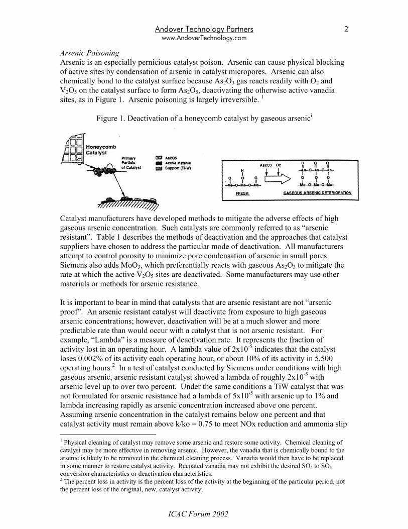
Arsenic Poisoning Arsenic is an especially pernicious catalyst poison. Arsenic can cause physical blocking of active sites by condensation of arsenic in catalyst micropores. Arsenic can also chemically bond to the catalyst surface because As2O3 gas reacts readily with O2 and V2O5 on the catalyst surface to form As2O5, deactivating the otherwise active vanadia sites, as in Figure 1. Arsenic poisoning is largely irreversible. 1
Figure 1. Deactivation of a honeycomb catalyst by gaseous arsenici
Catalyst manufacturers have developed methods to mitigate the adverse effects of high gaseous arsenic concentration. Such catalysts are commonly referred to as “arsenic resistant”. Table 1 describes the methods of deactivation and the approaches that catalyst suppliers have chosen to address the particular mode of deactivation. All manufacturers attempt to control porosity to minimize pore condensation of arsenic in small pores. Siemens also adds MoO3, which preferentially reacts with gaseous As2O3 to mitigate the rate at which the active V2O5 sites are deactivated. Some manufacturers may use other materials or methods for arsenic resistance. It is important to bear in mind that catalysts that are arsenic resistant are not “arsenic proof”. An arsenic resistant catalyst will deactivate from exposure to high gaseous arsenic concentrations; however, deactivation will be at a much slower and more predictable rate than would occur with a catalyst that is not arsenic resistant. For example, “Lambda” is a measure of deactivation rate. It represents the fraction of activity lost in an operating hour. A lambda value of 2x10⁻⁵ indicates that the catalyst loses 0.002% of its activity each operating hour, or about 10% of its activity in 5,500 operating hours.2 In a test of catalyst conducted by Siemens under conditions with high gaseous arsenic, arsenic resistant catalyst showed a lambda of roughly 2x10⁻⁵ with arsenic level up to over two percent. Under the same conditions a TiW catalyst that was not formulated for arsenic resistance had a lambda of 5x10⁻⁵ with arsenic up to 1% and lambda increasing rapidly as arsenic concentration increased above one percent. Assuming arsenic concentration in the catalyst remains below one percent and that catalyst activity must remain above k/ko = 0.75 to meet NOx reduction and ammonia slip 1 Physical cleaning of catalyst may remove some arsenic and restore some activity. Chemical cleaning of catalyst may be more effective in removing arsenic. However, the vanadia that is chemically bound to the arsenic is likely to be removed in the chemical cleaning process. Vanadia would then have to be replaced in some manner to restore catalyst activity. Recoated vanadia may not exhibit the desired SO2 to SO3 conversion characteristics or deactivation characteristics. 2 The percent loss in activity is the percent loss of the activity at the beginning of the particular period, not the percent loss of the original, new, catalyst activity.
ICAC Forum 2002
Andover Technology Partners www.AndoverTechnology.com
3
requirements, then the arsenic resistant catalyst will maintain adequate activity for about 14,000 hours versus about 5,500 hours for the catalyst that is not arsenic resistant. Therefore, the arsenic resistant catalyst still deactivates, but at a much slower rate than for the catalyst that is not formulated for arsenic resistance. Table 1. Mechanisms for Catalyst Deactivation by Arsenic and Methods to Mitigate
Deactivation Physical catalyst deactivation:
• Gaseous arsenic oxide molecules are much smaller than all catalyst pores • Pore condensation of arsenic starts in small pores • Small catalyst pores are a key to high catalyst activity by maintaining high
surface area • Pore condensation stops when filling of pores reaches equilibrium conditions • This mechanism of arsenic deactivation is typically addressed through control of
catalyst porosity to minimize migration of gaseous arsenic to small pores Chemical catalyst deactivation:
• Gaseous arsenic oxide molecules react with active V2O5 sites to form stable, non-catalytic compounds
• Chemical deactivation risk remains until all active sites are deactivated • MoO3 or other additives developed by catalyst manufacturers are more reactive
with As than V2O5 • Arsenic oxide preferentially reacts with MoO3 or other “sacrificial” additives to
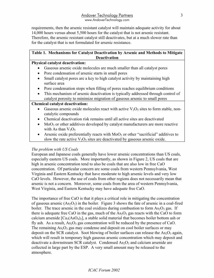
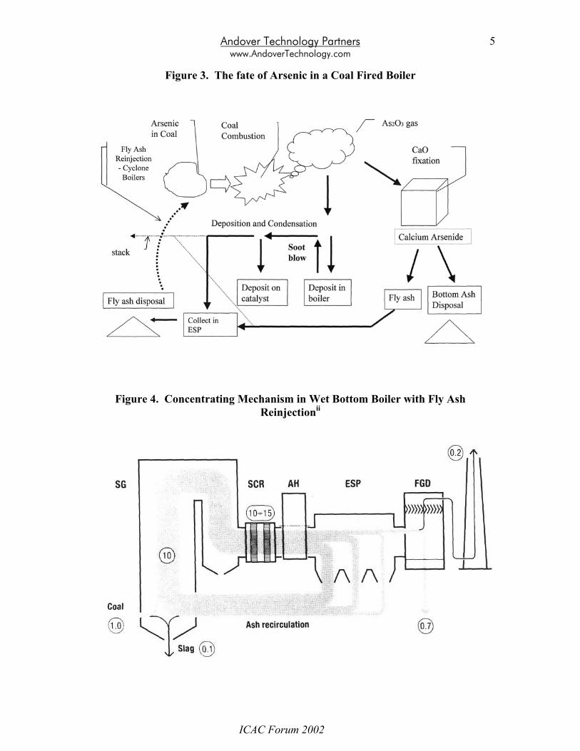
slow the rate active V2O5 sites are deactivated by gaseous arsenic oxide. The problem with US Coals European and Japanese coals generally have lower arsenic concentrations than US coals, especially eastern US coals. More importantly, as shown in Figure 2, US coals that are high in arsenic concentration tend to also be coals that are also low in free CaO concentration. Of particular concern are some coals from western Pennsylvania, West Virginia and Eastern Kentucky that have moderate to high arsenic levels and very low CaO levels. However, the use of coals from other regions does not necessarily mean that arsenic is not a concern. Moreover, some coals from the area of western Pennsylvania, West Virginia, and Eastern Kentucky may have adequate free CaO. The importance of free CaO is that it plays a critical role in mitigating the concentration of gaseous arsenic (As2O3) in the boiler. Figure 3 shows the fate of arsenic in a coal-fired boiler. The trace arsenic in the coal oxidizes during combustion to form As2O3 gas. If there is adequate free CaO in the gas, much of the As2O3 gas reacts with the CaO to form calcium arsenide [Ca3(AsO4)2], a stable solid material that becomes boiler bottom ash or fly ash. As a result, As2O3 gas concentration will be reduced by the presence of CaO. The remaining As2O3 gas may condense and deposit on cool boiler surfaces or may deposit on the SCR catalyst. Soot blowing of boiler surfaces can release the As2O3 again, which will result in temporary high gaseous arsenic concentration which may deposit and deactivate a downstream SCR catalyst. Condensed As2O3 and calcium arsenide are collected in large part by the ESP. A very small amount may be released to the atmosphere.
ICAC Forum 2002
Andover Technology Partners www.AndoverTechnology.com
4
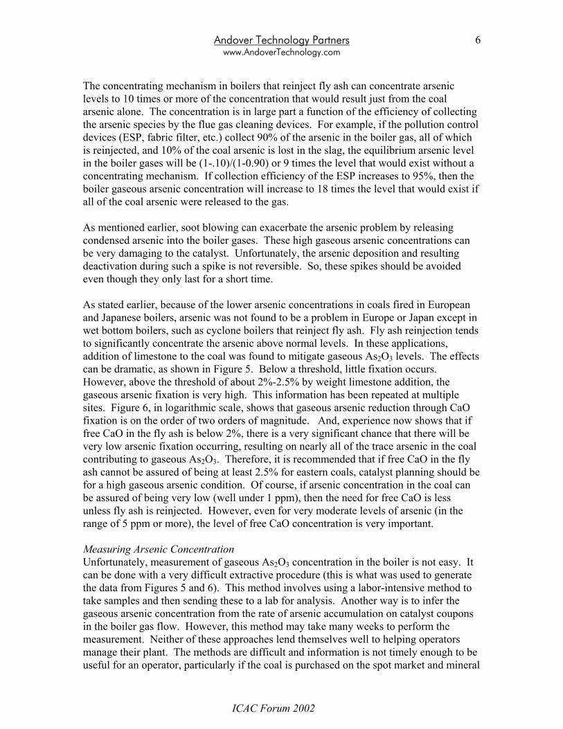
When fly ash is reinjected, such as in cyclone boilers, the arsenic collected in the ESP reenters the furnace, resulting in a concentrating mechanism that can increase arsenic concentration by a factor of ten or more over what it would otherwise be. This is because concentration builds up in the boiler gases until the amount that is leaving the boiler equilibrates to the same amount that is being input to the boiler from the coal. A higher collection efficiency in the particle-collecting device will result in a higher ultimate concentration. Figure 4 shows this concentrating mechanism schematically. Arsenic deactivation was, in fact, first identified as a problem in Europe on cyclone boilers that reinject fly ash. Although the concentration of arsenic in European coals is generally much less than that of US coals, the concentrating mechanism can be significant enough to cause high gaseous arsenic levels and rapid arsenic deactivation.
Figure 2. Arsenic in Ash versus CaO in Ashfor a variety of US Coals
0
50
100
150
200
250
0 1 2 3 4 5 6 7 8 9
CaO in Ash (%)
As
in A
sh (p
pm)
Multiply Arsenic (As) in ash concentration by coal ash concentration to determine As in coal concentration.
From Siemens Westinghouse Power Corporation
ICAC Forum 2002
Andover Technology Partners www.AndoverTechnology.com
5
Figure 3. The fate of Arsenic in a Coal Fired Boiler
Figure 4. Concentrating Mechanism in Wet Bottom Boiler with Fly Ash Reinjectionii
ICAC Forum 2002
Andover Technology Partners www.AndoverTechnology.com
6
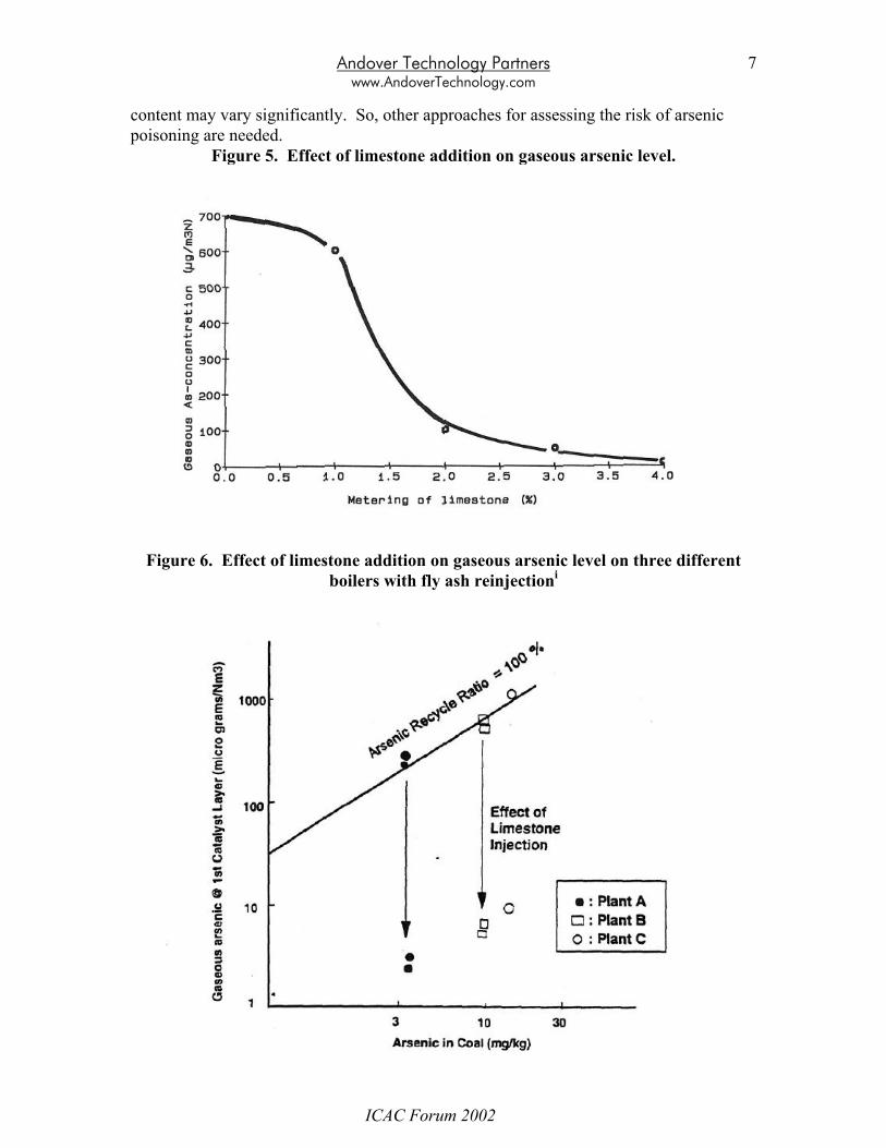
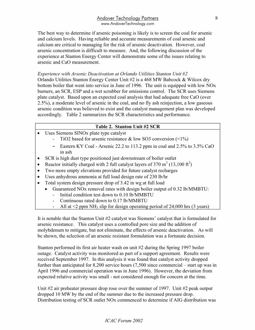
The concentrating mechanism in boilers that reinject fly ash can concentrate arsenic levels to 10 times or more of the concentration that would result just from the coal arsenic alone. The concentration is in large part a function of the efficiency of collecting the arsenic species by the flue gas cleaning devices. For example, if the pollution control devices (ESP, fabric filter, etc.) collect 90% of the arsenic in the boiler gas, all of which is reinjected, and 10% of the coal arsenic is lost in the slag, the equilibrium arsenic level in the boiler gases will be (1-.10)/(1-0.90) or 9 times the level that would exist without a concentrating mechanism. If collection efficiency of the ESP increases to 95%, then the boiler gaseous arsenic concentration will increase to 18 times the level that would exist if all of the coal arsenic were released to the gas. As mentioned earlier, soot blowing can exacerbate the arsenic problem by releasing condensed arsenic into the boiler gases. These high gaseous arsenic concentrations can be very damaging to the catalyst. Unfortunately, the arsenic deposition and resulting deactivation during such a spike is not reversible. So, these spikes should be avoided even though they only last for a short time. As stated earlier, because of the lower arsenic concentrations in coals fired in European and Japanese boilers, arsenic was not found to be a problem in Europe or Japan except in wet bottom boilers, such as cyclone boilers that reinject fly ash. Fly ash reinjection tends to significantly concentrate the arsenic above normal levels. In these applications, addition of limestone to the coal was found to mitigate gaseous As2O3 levels. The effects can be dramatic, as shown in Figure 5. Below a threshold, little fixation occurs. However, above the threshold of about 2%-2.5% by weight limestone addition, the gaseous arsenic fixation is very high. This information has been repeated at multiple sites. Figure 6, in logarithmic scale, shows that gaseous arsenic reduction through CaO fixation is on the order of two orders of magnitude. And, experience now shows that if free CaO in the fly ash is below 2%, there is a very significant chance that there will be very low arsenic fixation occurring, resulting on nearly all of the trace arsenic in the coal contributing to gaseous As2O3. Therefore, it is recommended that if free CaO in the fly ash cannot be assured of being at least 2.5% for eastern coals, catalyst planning should be for a high gaseous arsenic condition. Of course, if arsenic concentration in the coal can be assured of being very low (well under 1 ppm), then the need for free CaO is less unless fly ash is reinjected. However, even for very moderate levels of arsenic (in the range of 5 ppm or more), the level of free CaO concentration is very important. Measuring Arsenic Concentration Unfortunately, measurement of gaseous As2O3 concentration in the boiler is not easy. It can be done with a very difficult extractive procedure (this is what was used to generate the data from Figures 5 and 6). This method involves using a labor-intensive method to take samples and then sending these to a lab for analysis. Another way is to infer the gaseous arsenic concentration from the rate of arsenic accumulation on catalyst coupons in the boiler gas flow. However, this method may take many weeks to perform the measurement. Neither of these approaches lend themselves well to helping operators manage their plant. The methods are difficult and information is not timely enough to be useful for an operator, particularly if the coal is purchased on the spot market and mineral
ICAC Forum 2002
Andover Technology Partners www.AndoverTechnology.com
7
content may vary significantly. So, other approaches for assessing the risk of arsenic poisoning are needed.
Figure 5. Effect of limestone addition on gaseous arsenic level.
Figure 6. Effect of limestone addition on gaseous arsenic level on three different boilers with fly ash reinjectioni
ICAC Forum 2002
Andover Technology Partners www.AndoverTechnology.com
8
The best way to determine if arsenic poisoning is likely is to screen the coal for arsenic and calcium levels. Having reliable and accurate measurements of coal arsenic and calcium are critical to managing for the risk of arsenic deactivation. However, coal arsenic concentration is difficult to measure. And, the following discussion of the experience at Stanton Energy Center will demonstrate some of the issues relating to arsenic and CaO measurement. Experience with Arsenic Deactivation at Orlando Utilities Stanton Unit #2 Orlando Utilities Stanton Energy Center Unit #2 is a 468 MW Babcock & Wilcox dry bottom boiler that went into service in June of 1996. The unit is equipped with low NOx burners, an SCR, ESP and a wet scrubber for emissions control. The SCR uses Siemens plate catalyst. Based upon an expected coal analysis that had adequate free CaO (over 2.5%), a moderate level of arsenic in the coal, and no fly ash reinjection, a low gaseous arsenic condition was believed to exist and the catalyst management plan was developed accordingly. Table 2 summarizes the SCR characteristics and performance.
Table 2. Stanton Unit #2 SCR • Uses Siemens SINOx plate type catalyst
- TiO2 based for arsenic resistance & low SO3 conversion (<1%) - Eastern KY Coal - Arsenic 22.2 to 113.2 ppm in coal and 2.5% to 3.5% CaO
in ash • SCR is high dust type positioned just downstream of boiler outlet • Reactor initially charged with 2 full catalyst layers of 370 m3 (13,100 ft3) • Two more empty elevations provided for future catalyst recharges • Uses anhydrous ammonia at full load design rate of 230 lb/hr • Total system design pressure drop of 3.42 in wg at full load
• Guaranteed NOx removal rates with design boiler output of 0.32 lb/MMBTU: - Initial condition test down to 0.10 lb/MMBTU - Continuous rated down to 0.17 lb/MMBTU - All at <2 ppm NH3 slip for design operating period of 24,000 hrs (3 years)
It is notable that the Stanton Unit #2 catalyst was Siemens’ catalyst that is formulated for arsenic resistance. This catalyst uses a controlled pore size and the addition of molybdenum to mitigate, but not eliminate, the effects of arsenic deactivation. As will be shown, the selection of an arsenic resistant formulation was a fortunate decision. Stanton performed its first air heater wash on unit #2 during the Spring 1997 boiler outage. Catalyst activity was monitored as part of a support agreement. Results were received September 1997. In this analysis it was found that catalyst activity dropped further than anticipated for 8,200 service hours (7,500 since commercial – start up was in April 1996 and commercial operation was in June 1996). However, the deviation from expected relative activity was small - not considered enough for concern at the time. Unit #2 air preheater pressure drop rose over the summer of 1997. Unit #2 peak output dropped 10 MW by the end of the summer due to the increased pressure drop. Distribution testing of SCR outlet NOx commenced to determine if AIG distribution was
ICAC Forum 2002
Andover Technology Partners www.AndoverTechnology.com
9
poor and contributing to high ammonia slip. Results showed good distribution (standard deviation only 5.5%). By early 1998, maximum load was diminished by 38 MW due to the increased pressure drop across the air preheater. Wet chemistry tests during June 1998 found NH3 slip at over 8 ppm. Tests later that year found ammonia slip at 8.9 ppm, well above the guaranteed level of 2 ppm. By September 1998 Siemens had the results of the second catalyst sample tests. Siemens’ analysis showed that relative activity dropped well below the expected value - essentially twice as much deactivation as expected. And, arsenic concentration on the catalyst surface was found to be 2.71% by weight versus an expected 0.3%. Testing of the archived first outage samples, also found high arsenic at 2.30%. At this point, an outside consultant (Andover Technology Partners) was brought in to investigate the cause of the problem. A coupon test with fresh catalyst coupons was performed in September and October 1998 to verify arsenic poisoning and to estimate the level of gaseous arsenic loading in the SCR reactor. This test showed that arsenic concentrations in the gas were roughly between about 500 and 800 micrograms per normal cubic meter – gaseous arsenic concentrations that might be expected in a wet bottom boiler that reinjected its fly ash. This high level of arsenic concentration in the gas showed that arsenic deactivation was not a result of a one-time event (such as a single soot-blowing event or single load of coal), but is the result of a problem that persisted with Unit #2. Having established that the cause of deactivation was a persistently high gaseous arsenic condition, efforts commenced to determine the reason why high arsenic levels were present. Review of coal analyses for fuels that had been fired showed that coal arsenic levels were well below the expected range of 22.2 ppm to 113.2 ppm. The fuels purchasing laboratory contractor used ASTM method D4606-95 for the as-received analysis and the coal supplier used an unknown method for their analyses at the source. Although there was significant disagreement between the two methods, both were well below the expected arsenic range. The coal fired during the September/October 1998 coupon test was analyzed by the fuel department’s contract laboratory using ASTM D4606-95. This showed trace arsenic content in the coal of only 0.50 ppm, or about 5 ppm in the ash. Calculations showed that at these low arsenic levels, even if there were no calcium fixation occurring, the gaseous arsenic content would not reach the levels identified by the coupon test. In fact they were estimated to be on the order of 20 micrograms/normal cubic meter versus the 500 to 800 microgram/normal cubic meter indicated by the coupon test. A concentrating mechanism was, therefore, considered as a possible cause. Even though Stanton Unit #2 does not reinject fly ash, a careful mass balance was performed on the unit to determine if other methods might be at work to concentrate the arsenic. For example much of the ash of Unit #2 goes to the FGD sludge pond on site. A dewatering system sends water back to the boiler. This water was tested for arsenic. The result of the mass balance and testing found no evidence of a concentrating mechanism.
ICAC Forum 2002
Andover Technology Partners www.AndoverTechnology.com
10
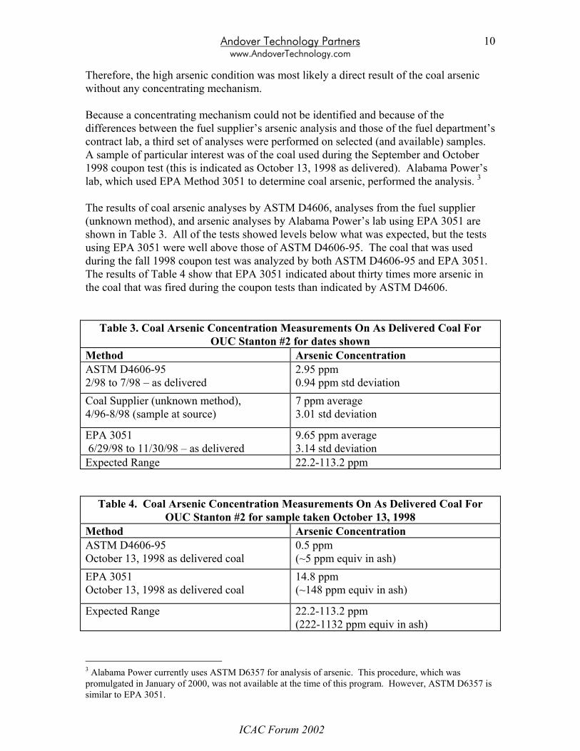
Therefore, the high arsenic condition was most likely a direct result of the coal arsenic without any concentrating mechanism. Because a concentrating mechanism could not be identified and because of the differences between the fuel supplier’s arsenic analysis and those of the fuel department’s contract lab, a third set of analyses were performed on selected (and available) samples. A sample of particular interest was of the coal used during the September and October 1998 coupon test (this is indicated as October 13, 1998 as delivered). Alabama Power’s lab, which used EPA Method 3051 to determine coal arsenic, performed the analysis. 3 The results of coal arsenic analyses by ASTM D4606, analyses from the fuel supplier (unknown method), and arsenic analyses by Alabama Power’s lab using EPA 3051 are shown in Table 3. All of the tests showed levels below what was expected, but the tests using EPA 3051 were well above those of ASTM D4606-95. The coal that was used during the fall 1998 coupon test was analyzed by both ASTM D4606-95 and EPA 3051. The results of Table 4 show that EPA 3051 indicated about thirty times more arsenic in the coal that was fired during the coupon tests than indicated by ASTM D4606.
Table 3. Coal Arsenic Concentration Measurements On As Delivered Coal For OUC Stanton #2 for dates shown
Method Arsenic Concentration ASTM D4606-95 2/98 to 7/98 – as delivered
2.95 ppm 0.94 ppm std deviation
Coal Supplier (unknown method), 4/96-8/98 (sample at source)
7 ppm average 3.01 std deviation
EPA 3051 6/29/98 to 11/30/98 – as delivered
9.65 ppm average 3.14 std deviation
Expected Range 22.2-113.2 ppm
Table 4. Coal Arsenic Concentration Measurements On As Delivered Coal For OUC Stanton #2 for sample taken October 13, 1998
Method Arsenic Concentration ASTM D4606-95 October 13, 1998 as delivered coal
0.5 ppm (~5 ppm equiv in ash)
EPA 3051 October 13, 1998 as delivered coal
14.8 ppm (~148 ppm equiv in ash)
Expected Range 22.2-113.2 ppm (222-1132 ppm equiv in ash)
3 Alabama Power currently uses ASTM D6357 for analysis of arsenic. This procedure, which was promulgated in January of 2000, was not available at the time of this program. However, ASTM D6357 is similar to EPA 3051.
ICAC Forum 2002

Andover Technology Partners www.AndoverTechnology.com
11
ICAC Forum 2002
Andover Technology Partners www.AndoverTechnology.com
12
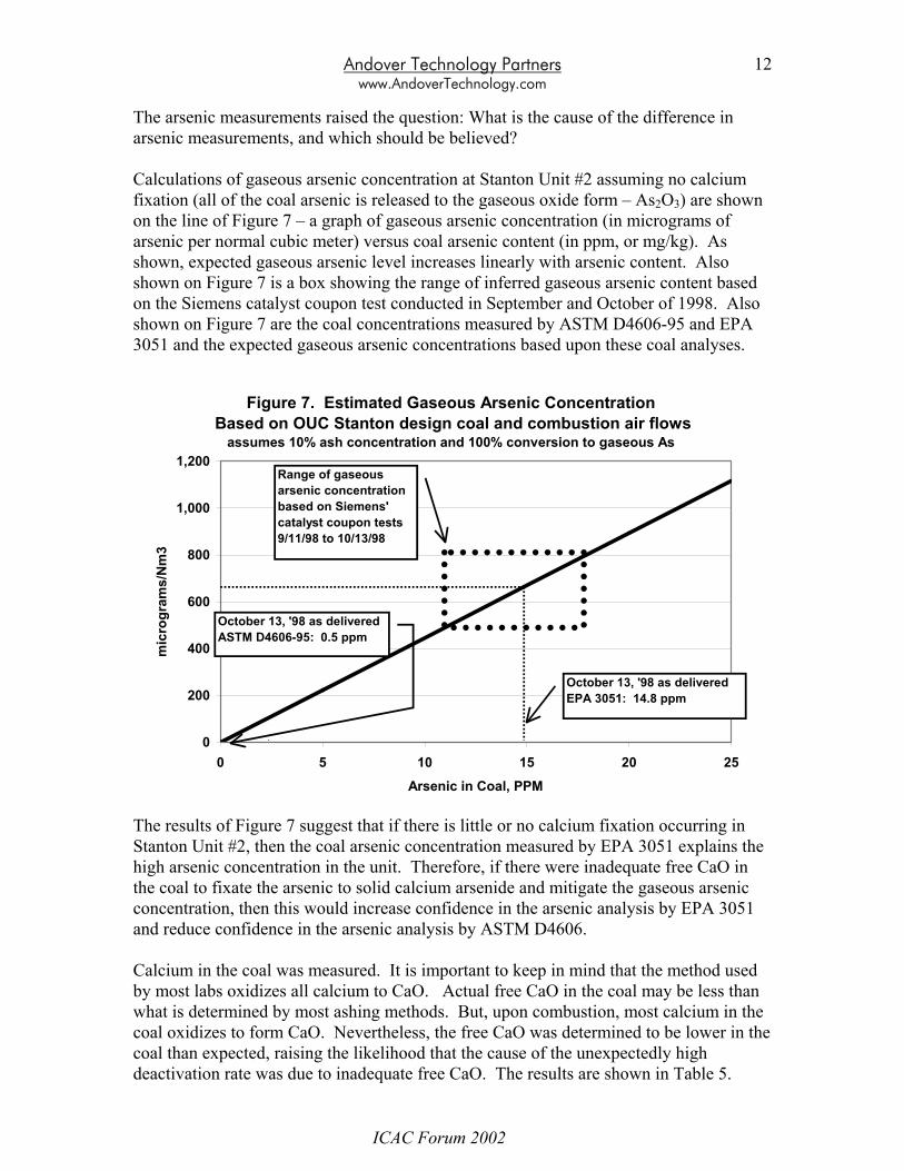
The arsenic measurements raised the question: What is the cause of the difference in arsenic measurements, and which should be believed? Calculations of gaseous arsenic concentration at Stanton Unit #2 assuming no calcium fixation (all of the coal arsenic is released to the gaseous oxide form – As2O3) are shown on the line of Figure 7 – a graph of gaseous arsenic concentration (in micrograms of arsenic per normal cubic meter) versus coal arsenic content (in ppm, or mg/kg). As shown, expected gaseous arsenic level increases linearly with arsenic content. Also shown on Figure 7 is a box showing the range of inferred gaseous arsenic content based on the Siemens catalyst coupon test conducted in September and October of 1998. Also shown on Figure 7 are the coal concentrations measured by ASTM D4606-95 and EPA 3051 and the expected gaseous arsenic concentrations based upon these coal analyses.
Figure 7. Estimated Gaseous Arsenic Concentration Based on OUC Stanton design coal and combustion air flows
assumes 10% ash concentration and 100% conversion to gaseous As
0
200
400
600
800
1,000
1,200
0 5 10 15 20 25Arsenic in Coal, PPM
mic
rogr
ams/
Nm
3
October 13, '98 as deliveredEPA 3051: 14.8 ppm
October 13, '98 as deliveredASTM D4606-95: 0.5 ppm
Range of gaseous arsenic concentration based on Siemens' catalyst coupon tests9/11/98 to 10/13/98
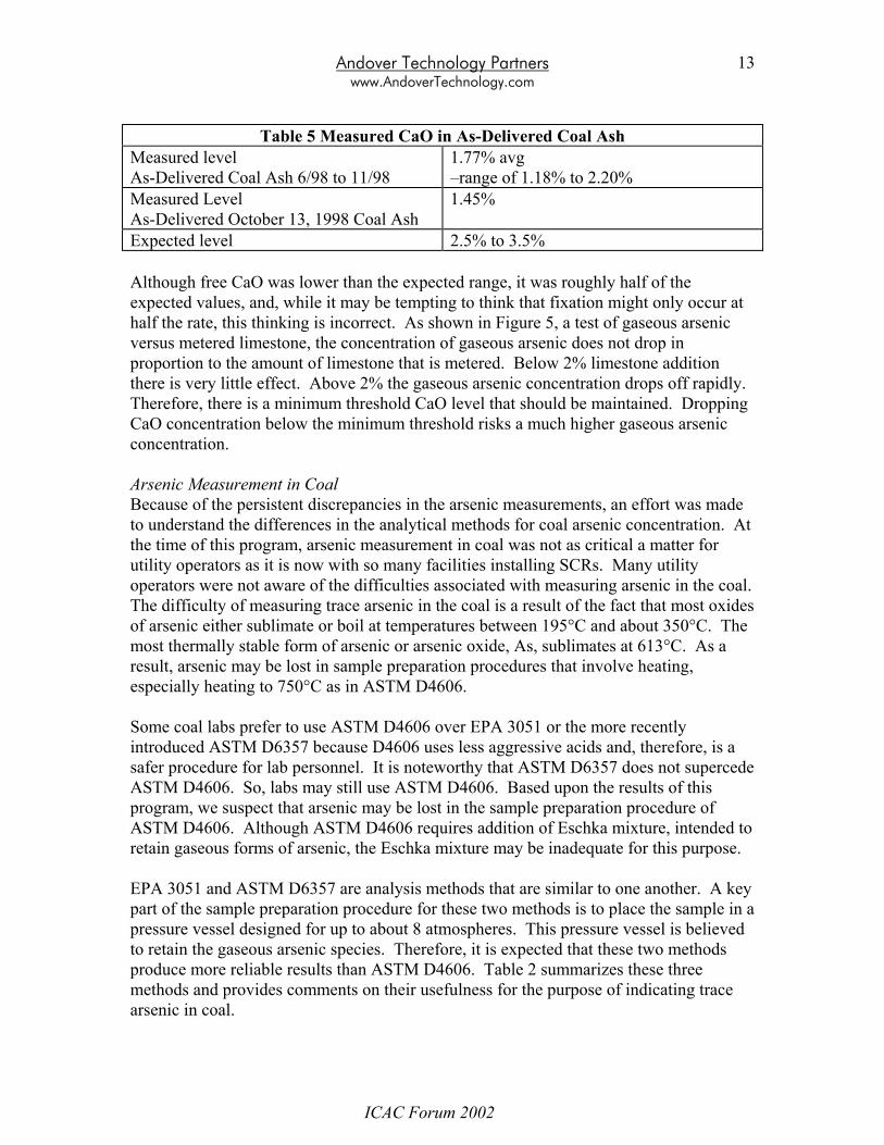
The results of Figure 7 suggest that if there is little or no calcium fixation occurring in Stanton Unit #2, then the coal arsenic concentration measured by EPA 3051 explains the high arsenic concentration in the unit. Therefore, if there were inadequate free CaO in the coal to fixate the arsenic to solid calcium arsenide and mitigate the gaseous arsenic concentration, then this would increase confidence in the arsenic analysis by EPA 3051 and reduce confidence in the arsenic analysis by ASTM D4606. Calcium in the coal was measured. It is important to keep in mind that the method used by most labs oxidizes all calcium to CaO. Actual free CaO in the coal may be less than what is determined by most ashing methods. But, upon combustion, most calcium in the coal oxidizes to form CaO. Nevertheless, the free CaO was determined to be lower in the coal than expected, raising the likelihood that the cause of the unexpectedly high deactivation rate was due to inadequate free CaO. The results are shown in Table 5.
ICAC Forum 2002
Andover Technology Partners www.AndoverTechnology.com
13
Table 5 Measured CaO in As-Delivered Coal Ash
Measured level As-Delivered Coal Ash 6/98 to 11/98
1.77% avg –range of 1.18% to 2.20%
Measured Level As-Delivered October 13, 1998 Coal Ash
1.45%
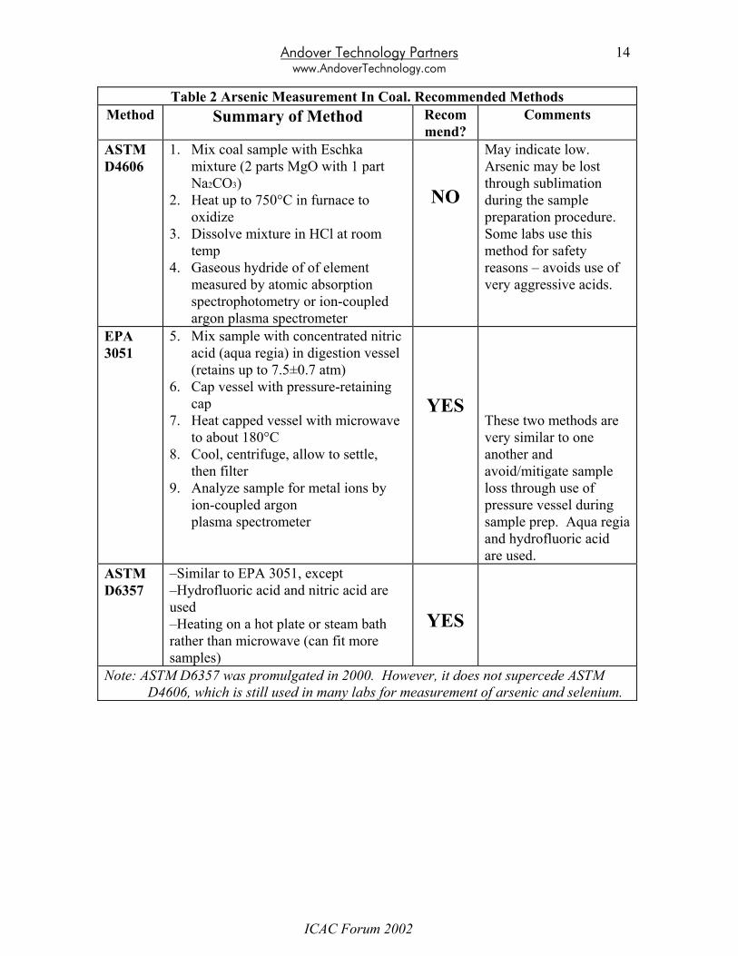
Expected level 2.5% to 3.5% Although free CaO was lower than the expected range, it was roughly half of the expected values, and, while it may be tempting to think that fixation might only occur at half the rate, this thinking is incorrect. As shown in Figure 5, a test of gaseous arsenic versus metered limestone, the concentration of gaseous arsenic does not drop in proportion to the amount of limestone that is metered. Below 2% limestone addition there is very little effect. Above 2% the gaseous arsenic concentration drops off rapidly. Therefore, there is a minimum threshold CaO level that should be maintained. Dropping CaO concentration below the minimum threshold risks a much higher gaseous arsenic concentration. Arsenic Measurement in Coal Because of the persistent discrepancies in the arsenic measurements, an effort was made to understand the differences in the analytical methods for coal arsenic concentration. At the time of this program, arsenic measurement in coal was not as critical a matter for utility operators as it is now with so many facilities installing SCRs. Many utility operators were not aware of the difficulties associated with measuring arsenic in the coal. The difficulty of measuring trace arsenic in the coal is a result of the fact that most oxides of arsenic either sublimate or boil at temperatures between 195°C and about 350°C. The most thermally stable form of arsenic or arsenic oxide, As, sublimates at 613°C. As a result, arsenic may be lost in sample preparation procedures that involve heating, especially heating to 750°C as in ASTM D4606. Some coal labs prefer to use ASTM D4606 over EPA 3051 or the more recently introduced ASTM D6357 because D4606 uses less aggressive acids and, therefore, is a safer procedure for lab personnel. It is noteworthy that ASTM D6357 does not supercede ASTM D4606. So, labs may still use ASTM D4606. Based upon the results of this program, we suspect that arsenic may be lost in the sample preparation procedure of ASTM D4606. Although ASTM D4606 requires addition of Eschka mixture, intended to retain gaseous forms of arsenic, the Eschka mixture may be inadequate for this purpose. EPA 3051 and ASTM D6357 are analysis methods that are similar to one another. A key part of the sample preparation procedure for these two methods is to place the sample in a pressure vessel designed for up to about 8 atmospheres. This pressure vessel is believed to retain the gaseous arsenic species. Therefore, it is expected that these two methods produce more reliable results than ASTM D4606. Table 2 summarizes these three methods and provides comments on their usefulness for the purpose of indicating trace arsenic in coal.
ICAC Forum 2002
Andover Technology Partners www.AndoverTechnology.com
14
Table 2 Arsenic Measurement In Coal. Recommended Methods Method Summary of Method Recom
mend? Comments
ASTM D4606
1. Mix coal sample with Eschka mixture (2 parts MgO with 1 part Na2CO3)
2. Heat up to 750°C in furnace to oxidize
3. Dissolve mixture in HCl at room temp
4. Gaseous hydride of of element measured by atomic absorption spectrophotometry or ion-coupled argon plasma spectrometer
NO
May indicate low. Arsenic may be lost through sublimation during the sample preparation procedure. Some labs use this method for safety reasons – avoids use of very aggressive acids.
EPA 3051
5. Mix sample with concentrated nitric acid (aqua regia) in digestion vessel (retains up to 7.5±0.7 atm)
6. Cap vessel with pressure-retaining cap
7. Heat capped vessel with microwave to about 180°C
8. Cool, centrifuge, allow to settle, then filter
9. Analyze sample for metal ions by ion-coupled argon plasma spectrometer
YES
These two methods are very similar to one another and avoid/mitigate sample loss through use of pressure vessel during sample prep. Aqua regia and hydrofluoric acid are used.
ASTM D6357
–Similar to EPA 3051, except –Hydrofluoric acid and nitric acid are used –Heating on a hot plate or steam bath rather than microwave (can fit more samples)
YES
Note: ASTM D6357 was promulgated in 2000. However, it does not supercede ASTM D4606, which is still used in many labs for measurement of arsenic and selenium.
ICAC Forum 2002
Andover Technology Partners www.AndoverTechnology.com
ICAC Forum 2002
15
Stanton’s Options for the Future Stanton Unit #2 had three options for continued operation:
1. Continue to operate with a different catalyst management plan that entailed more frequent or larger catalyst additions than originally planned
2. Inject limestone in an attempt to reduce the gaseous arsenic concentration 3. Change fuels to one with higher free CaO content in the coal
The decision was made to follow the first path based on economic and risk considerations. However, the station is still considering the other alternatives and the possibility of catalyst regeneration as potential alternatives that may be used at some point in the future when economic and technical risk questions are adequately answered. For the time being, the plant has been able to maintain 3-year operating cycles on the catalyst layer addition/replacement. 2002 will mark the second 3-year operating cycle, and the plant is just now beginning to see the effects of diminished activity on the ammonia slip. Had Stanton not used a catalyst formulated for arsenic resistance, the 3-year operating cycle for the catalyst changes would not be possible. The cycle would be reduced possibly to one year if a conventional (not arsenic resistant) catalyst formulation were used. Implications for Other Facilities The implications of this program for other facilities can be summarized as follows:
• The concentration of free CaO in the coal ash is just as important, if not more so, in determining the risk of high arsenic deactivation rates.
• Coal Arsenic concentration should be measured by EPA 3051 or ASTM D6357. Use of ASTM D4606 risks indicating lower coal arsenic than actually exists, which may provide a false sense of security.
• When switching coals or buying on the spot market, coal mineral analyses must be carefully evaluated to assure that arsenic and CaO are in the proper range.
• If any risk of high arsenic conditions are expected due to coal purchasing behavior, boiler operations, or other reasons, then a catalyst formulated for arsenic resistance should be selected.
References
i Pritchard, S., DiFrancesco, C., Kaneko, S., Kobayashi, N., Suyama, K., Iida, K., “Optimizing SCR
Catalyst Design and Performance for Coal-Fired Boilers”, EPRI/EPA 1995 Joint Symposium on Stationary Combustion NOx Control, Kansas City, May 16-19, 1995.
ii Balling, L., Sigling, R., Schmelz, H., Hums, E., Spitznagel, G., “Poisoning Mechanisms in Existing SCR Catalytic Converters and Development of a New Generation for Improvement of the Catalytic Properties”, EPRI/EPA 1993 Joint Symposium on Stationary Combustion NOx Control, Miami, May 24-27, 1993.