properties of borided sae 1035 steels and fracture ... · properties of borided sae 1035 steels and...
TRANSCRIPT
Properties of borided SAE 1035 steels and fracture toughness produced by Vickers indentation
A. Kaouka1, O. Allaoui1, M. Keddam2 & S.Taktak3 1Laboratoire de Génie des Procèdes, Université Amar Telidji – Laghouat, Algeria 2Département de Sciences des Matériaux, Faculté de Genie Mécanique, USTHB, Algeria
3Technical Education Faculty, Department of Metal Education, Afyon Kocatepe University, Turkey
Abstract
Boriding in a salt bath consisting of borax, boric acid, ferro-silicon was carried out at a temperature range of 1123, 1173, 1223, and 1273 K, for 4 and 8 h, using a Vickers microhardness tester to generate cracks with applying loads (0.49, 0.98, 1.96, 4.9 and 9.8N). A Vickers indenter was used to estimate the fracture toughness values of borided SAE1035 steel. The microcrack was made through the thickness of the boride layer of SAE1035 steel at different distances from surface. The presence of borides phases was revealed by X-ray diffraction, SEM, and optical microscopy. Experimental results showed that the fracture toughness values obtained using Palmqist crack model were ranged from 2.92 to 3.75 MPa.m1/2, increasing of boriding time and temperature leads to reduction of fracture toughness of borides. Keywords: boride layer, boriding, steel SAE1035, toughness, Vickers indentation..
1 Introduction
Boriding is a thermochemical surface hardening process in which boron atoms are diffused into the surface, the boride layer is formed on the base metal at high temperature [1, 2], aiming to improve the wear resistance, abrasion and
Surface Effects and Contact Mechanics XI 183
www.witpress.com, ISSN 1743-3533 (on-line) WIT Transactions on Engineering Sciences, Vol 78, © 2013 WIT Press
doi:10.2495/SECM130 115

corrosion, which consists of a saturation of boron to the surface. There are two types of layers: FeB which is rich in boron, more ductile and harder than Fe2B [3]. The formation of two phases depends on the temperature, time treatment and the chemical composition of the substrate. The hardness of iron borides formed on the surfaces of steels is over 2100 HV [4, 5].The borides are likely creating a high porosity when there is a saturation of boron on the surface and high processing temperatures, and the wear resistance of boride layer is related to the toughness. Vickers indentation is widely used to characterize the mechanical properties of brittle materials as their hardness, their elasticity modulus, and the fracture toughness values. The indentation technique requires a flat and polished surface, only a few authors have determined the fracture toughness in phases FeB and Fe2B, using hardness testing Vickers [5–8]. Lawn and Wilshaw [9] propose the Vickers indentation test to calculate the toughness from the fracture mechanics theory, which is based on the analysis of stress field in the point of contact and establish in genealogy with the fracture toughness (Kc), which is mainly dependent on the geometry of the indenter and the applied load. For the case of steels borides, it would be more appropriate to use relation based on Palmqvist crack morphology [10]. In the work presented by Shetty et al. [11], they proposed an empirical equation (1) in the regime Palmqvist crack for the evaluation of fracture toughness KC.
0.0319( / )CK P d a
(1) (P) is the indentation load, (a) is the length of the crack occurred in the corners of the indentation, and (d) is half the length of the diagonal of the indenter. In this work, the fact was evaluated under the experimental parameters of 4 and 8 h of treatment for different temperatures of the process of boriding at 1123, 1173, 1223, and 1273 K, considering the length of the cracks, perpendicular to the surface that comes to the end of an impression behind. In addition, the Young’s modulus of the layer of borides was estimated for all experiments, retention values microhardness are 1600 to 2200 HV [12]. The condition prevails as long as the load (P), the crack size (c) and χ is a dimensionless constant [13].
3/ 2( / )CK X P C
(2)
1/20.028( / )X E H
(3) E and H being Young’s modulus and Vickers microhardness of the Fe2B phase, respectively. The dotted indentations are privileged for the analysis of the fracture toughness, because the contact pressure is independent of the size of the indentation and the crack propagates to the peaks of residual impression [14, 15]. This study evaluates the fracture toughness (Kc) of the phase structure Fe2B of SAE1035 steel substrate, behavior it is based on the distance of the load applied to the thickness of the layer boride. We investigated some mechanical properties of SAE1035 steel boride. Especially, the fracture toughness of borides (Kc) was determined by means Vickers indenter formed on the surfaces of steel
184 Surface Effects and Contact Mechanics XI
www.witpress.com, ISSN 1743-3533 (on-line) WIT Transactions on Engineering Sciences, Vol 78, © 2013 WIT Press

substrates, also morphology of boride layers by scanning electron microscopy, optical microscopy, X-ray diffraction analysis and Vickers hardness test, respectively.
2 Experimental procedure
2.1 Process boriding
SAE1035 steel samples were machined dimensions of 13 mm x 13 mm x 9 mm, just before boriding treatment; specimens were ground up to 1200 mesh emery abrasive paper and polished. The chemical compositions of base steels used in this study are given in Table 1. The process was carried out in a salt bath consisting of borax (60 wt%) and boric acid (20 wt%) as a boron source and ferrosilicon (20 wt%) as the activator ,at temperatures of 1123, 1173, 1223, and 1273 K, with exposure times of 4 and 8 h. Having completed the boriding heat treatment, test materials were removed from the bath and quenched in air.
Table 1: Chemical composition of the SAE1035 steel.
Elements % (wt)
C 0.45
Mn 0.76
Si 0.34
P 0.028
S 0.033
Cu 0.18
Cr 0.19
Ni 0.26
Fe Balance
2.2 Microstructure
Optical examinations of cross sections of borided SAE1035 steel surfaces were examined using an Olympus BX60 optical microscopy, and the boride layer thickness was measured by means of an optical micrometer attached to the same apparatus citied. The Thickness values given in the results section are averages of at least 10 measurements. Scanning electron microscopy (SEM) was performed on polished cross-sections of borided samples using a LEO1430VP instrument. The presence of borides formed in the coating layer was confirmed by means of X-ray diffraction using Cu Ka radiation.
Surface Effects and Contact Mechanics XI 185
www.witpress.com, ISSN 1743-3533 (on-line) WIT Transactions on Engineering Sciences, Vol 78, © 2013 WIT Press

2.3 Microhardness and fracture toughness
The microhardness of boride steel samples was also measured using SHIMADZU microhardness tester fitted with a Vickers indenter and at a load of 0.1, 0.2, 0.3, 0.5 and 1Kg. also used for the calculation of fracture toughness. 10 measurements were taken for each distance, load, time, and temperature of treatment.
3 Results and discussion
3.1 Microstructure
Optical cross sectional examinations of boride steel SAE 1035 surfaces showed that the morphologies of boride layers are smooth and flat. The microstructures of SAE1035 borided steel are shown in Figure 1. A thin boride layer was formed on the surface of SAE1035 steel, and depth of layers Fe2B was observed. Optical microscopy was shown that the more time boriding and the higher the temperature, the thicker boride layers were obtained as shown in Figure 2. Optical and SEM cross sectional examinations of the borided steel surfaces revealed a columnar morphology with a depth until 384 µm. Figure 3 shows a SEM cross of borided SAE1035 steel revealed the saw tooth morphology of borides. The present phases of borided layers were determined by X-ray diffraction (XRD) analysis. Figure 4 showed that the dominant phases formed in coating layer are FeB, and Fe2B. The present results are according with literature [16–18].
(a) (b)
Figure 1: Optical cross sectional view of boronized SAE1035 steel: (a) at 850°C for 4 h; (b) at 950°C for 4 h.
186 Surface Effects and Contact Mechanics XI
www.witpress.com, ISSN 1743-3533 (on-line) WIT Transactions on Engineering Sciences, Vol 78, © 2013 WIT Press
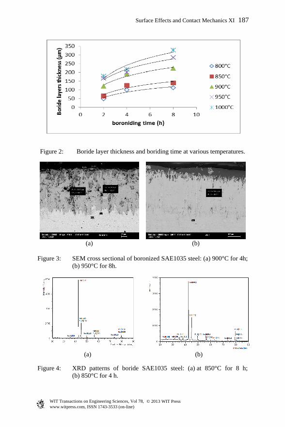
Figure 2: Boride layer thickness and boriding time at various temperatures.
(a) (b)
Figure 3: SEM cross sectional of boronized SAE1035 steel: (a) 900°C for 4h; (b) 950°C for 8h.
(a) (b)
Figure 4: XRD patterns of boride SAE1035 steel: (a) at 850°C for 8 h; (b) 850°C for 4 h.
Surface Effects and Contact Mechanics XI 187
www.witpress.com, ISSN 1743-3533 (on-line) WIT Transactions on Engineering Sciences, Vol 78, © 2013 WIT Press

(a) (b)
Figure 5: Indentation to perform the crack size for load of 200 g: (a) 950°C for 2h, (b) 950°C for 4h.
3.2 Microhardness and fracture toughness
Determination of fracture toughness by Vickers, the sample is set back to create a deformed zone below and close to printing, leading to the generation of cracks emanating from the corners of the impression that Vickers diamond square, testing of Vickers microhardness were performed with the tester HVS microhardness in the samples packed at 1123, 1173, 1223 and 1273 K, with the exposure time of 4 and 8 h, with charge of 0.1, 0.2, 0.3, 0.5 and 1Kg were applied during the phase Fe2B at a constant distance from the surface (30µm) to obtain a variation of the size of indentation Vickers and to perform the measurement of the crack size, a constant load of 200 g was applied during the phase of Fe2B, as shown in Figure 5. The average values of microhardness of borided steel SAE 1035 were 1840 and 2050 HV0.1. The distribution of Vickers hardness values of boride layers in the borided steels is shown in Figure 6. Depth of the borided layer and hardness increased with treatment temperature and time. For values of fracture toughness, both Vickers diagonal (D) and crack length (a) were measured in an Olympus BX60 microscope. Tool for measuring the thickness was used to carry out the measurements. The model proposed by K. Shetty et al. [19] was used to estimate the fracture toughness values of the layer Fe2B. Fracture toughness determined by the Vickers indentation, which leads to the generation of cracks emanating from the corners of the square Vickers diamond impression. The lengths of the cracks, along with the indentation load, the impression size, the hardness and elastic modulus of the material. The steel surface was covered with a layer of boride Fe2B phase, it was reported that boron diffuses faster along the [001] direction due to the tendency of boride crystals grow along a direction of least resistance [20].
188 Surface Effects and Contact Mechanics XI
www.witpress.com, ISSN 1743-3533 (on-line) WIT Transactions on Engineering Sciences, Vol 78, © 2013 WIT Press

Figure 6: Variation of Boride layer hardness with boriding time at various temperatures.
Figure 7: Palmqvist crack of indentation distribution during the phase Fe2B.
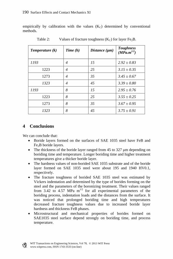
In the present work, the thickness of the boride layer was assessed by considering the average values of long teeth, depending on the boriding parameters. The number of taps at the boride layer was created by three experimental parameters: the thickness of the boride layer, the indentation size printing, and the applied load. For representative values of hardness of boride Fe2B, the indentations should not be close to the interphase layer/substrate [21]. The toughness of various steels borides can vary from was ranged from 2.92 to 3.75 (MPa.m1/2) as shown in table 2. In addition, the various models in the regime under Vickers indentation Palmqvist are proposed in the literature [22, 23]. For 0.25 / 2.5a d
2/50.0122( / ) ( / )CK E H P d a
(4)
2/50.0089( / ) ( / )CK E H P d a
(5)
where E is the Young’s modulus and H is the Vickers hardness value. The only real difference of these equations is their coefficients and those usually obtained
Surface Effects and Contact Mechanics XI 189
www.witpress.com, ISSN 1743-3533 (on-line) WIT Transactions on Engineering Sciences, Vol 78, © 2013 WIT Press
empirically by calibration with the values (KC) determined by conventional methods.
Table 2: Values of fracture toughness (KC) for layer Fe2B.
Temperature (k) Time (h) Distance (µm) Toughness (MPa.m1/2)
1193 4 15 2.92 ± 0.83
1223 4 25 3.15 ± 0.35
1273 4 35 3.45 ± 0.67
1323 4 45 3.39 ± 0.80
1193 8 15 2.95 ± 0.76
1223 8 25 3.55 ± 0.25
1273 8 35 3.67 ± 0.95
1323 8 45 3.75 ± 0.91
4 Conclusions
We can conclude that: Boride layers formed on the surfaces of SAE 1035 steel have FeB and
Fe2B boride layers. The thickness of the boride layer ranged from 45 to 327 μm depending on
boriding time and temperature. Longer boriding time and higher treatment temperatures give a thicker boride layer.
The hardness values of non-borided SAE 1035 substrate and of the boride layer formed on SAE 1035 steel were about 195 and 1940 HV0.1, respectively.
The fracture toughness of borided SAE 1035 steel was estimated by Vickers indentation and determined by the type of borides forming on the steel and the parameters of the boronizing treatment. Their values ranged from 3.42 to 4.57 MPa m1/2 for all experimental parameters of the boriding process, indentation loads and the distances from the surface. It was noticed that prolonged boriding time and high temperatures decreased fracture toughness values due to increased boride layer hardness and thickness FeB phases.
Microstructural and mechanical properties of borides formed on SAE1035 steel surface depend strongly on boriding time, and process temperature.
190 Surface Effects and Contact Mechanics XI
www.witpress.com, ISSN 1743-3533 (on-line) WIT Transactions on Engineering Sciences, Vol 78, © 2013 WIT Press

References
[1] Sinha, A. K. Boriding (Boronizing), ASM Handbook, OH, USA, J. Heat Treat. vol. 4, pp. 437.1991.
[2] Erdemir, A. Bindal, C. Surf. Coat. Technol. 76, pp. 443–449, 1995. [3] Matuschka, A. Boriding, Carl HanserVerlag, Munich, 1980. [4] Shetty, D. K. Wright, I.G. Mincer, P.N. J. Mater. Sci. 20, pp. 1873–1882,
1985. [5] Uslu, I. Comert, H. Ipek, M. Ozdemir, O. Bindal, C. Mater. Design 28,
pp 1819–1826, 2007. [6] Ozbek, C. Bindal. Surf. Coat. Technol. 154, pp. 14, 2002. [7] Sen, U. Sen, S. Yilmaz, F. Mater. Process. Technol. 148, pp. 2004. [8] Lawn, B. Fracture of Brittle Solids. Cambridge Solid State Science Series,
1993. [9] Lawn, B. Wilshaw, R. J. Mater. Sci. 10, pp. 1049, 1995. [10] Campos-Silva, I. Balankin, A. Sierra, A.H. Escobar-Galindo, R. López-
Perrusquia, N. Morales-Matamoros D. Appl. Surf. Sci. 255, pp. 2596–2602. 2008.
[11] Shetty, D. K. Wright, I. G. Mincer. P.N. J. Mater. Sci. 20, pp. 1873–1882, 1985.
[12] Kartal, G. Timur, S. Urgen, M. Erdemir, A. Surf. Coat. Technol. 204, pp. 3935, 2010.
[13] Allaoui, O. Bouaouadja, N. Saindeman, G. “Characterization of boronized layers on an XC38 steel,” Surf. Coat. Tech. Vol. 201, pp. 3475–3482.
[14] Campos-Silva, I. Balankin A., Sierra, A.H. Appl. Surf. Sci. 255, 2596–2602, 2008.
[15] Ozbek, I. Bindal, C. Surf. Coat. Technol. 154, p. 14, 2002. [16] Taktak, S. Mater. Des. 28, pp. 1836–1843, 2007 [17] Campos-Silva, I. Ortiz-Dominguez, M. Hernández-Sánchez, E. Bravo-
Bárcenas, O. Bravo-Bárcenas, M. A. Doñu-Ruíz, J. Martínez-Trinidad, G. Jiménez-Bernal, J.A. Domínguez-Galicia, Y. Key Engineering Materials. 449, pp. 9–14. 2010.
[18] Sen, U. Sen, S. Materials Characterization. 50, pp. 261–267. 2003 [19] Shetty, D.K. Wright, I. G. Mincer, P.N.J. Mater. Sci. 20, pp. 1873–1882.
1985. [20] Keddam. M. Appl. Surf. Sci. 236, pp. 451-455. 2004. [21] Badini, C. Gianoglio, C. Pradelli, P. Surf. Coat. Technol. 30, pp. 157–170.
1987. [22] Uslu, I. H. Comert, Ipek, M. Ozdemir, O. Bindal, C. Mater. Design 28,
pp. 55–61, 2007. [23] Sen, U. Sen, S. Koksal, S. Yilmaz. F. Mater. Design. 26, pp.175–179, 2005.
Surface Effects and Contact Mechanics XI 191
www.witpress.com, ISSN 1743-3533 (on-line) WIT Transactions on Engineering Sciences, Vol 78, © 2013 WIT Press