proplus 3ph basic electronic panel - manuales y ...help.ako.com/assets/uploads/351569042-1.pdf ·...
TRANSCRIPT

AKO-1569x AKO-1569x-EVC
PROPlus 3PH BASIC Electronic Panel
GB 1569H042 Ed.02
User Manual

2
AKO Electromecànica thanks you and congratulates you on the purchase of our product, the development and manufacture of which involved the most innovative technologies, as well as rigorous production and quality control processes. Our commitment to achieving customer satisfaction and our continuous efforts to improve day by day are confirmed by the various quality certificates obtained.This is a high performance, technologically advanced product. Its operation and the final performance achieved will depend, to a great extent, on correct planning, installation, configuration and commissioning. Please read this manual carefully before proceeding to install it and respect the instructions in the manual at all times. Only qualified personnel may install the product or carry out technical support.This product has been developed for use in the applications described in the manual. AKO Electromecànica does not guarantee its operation in any use not foreseen in this document and accepts no liability in the case of damage of any type which may result from incorrect use, configuration, installation or commissioning. Complying with and enforcing the regulations applying to installations where our products are destined to be used is the responsibility of the installer and the customer. AKO Electromecànica accepts no liability for damage which may occur due to failure to comply with these regulations. Rigorously follow the instructions described in this manual.In order to extend the lifetime of our products to the maximum, the following points must be observed:
Do not expose electronic equipment to dust, dirt, water, rain, moisture, high temperatures, chemical agents or corrosive substances of any type.Do not subject equipment to knocks or vibrations or attempt to handle them in any way differently to that indicated in the manual.Do not under any circumstances exceed the specifications and limitations indicated in the manual.Respect the indicated environmental conditions for operation and storage at all times.During installation and on completion of this, avoid the presence of loose, broken or unprotected cables or cables in poor condition. These may constitute a risk for the equipment and its users.
AKO Electromecànica reserves the right to make any modification to the documentation and the product without prior notification.
Index Page
1.- Presentation ..............................................................................................................................31.1.- Maintenance ...................................................................................................................31.2.- Precauciones ...................................................................................................................3
2.- Versions and references .............................................................................................................33.- Installation ...............................................................................................................................44.- Recommendations .....................................................................................................................75.- Description ...............................................................................................................................8
5.1.- Quick access to functions ................................................................................................85.2.- Messages........................................................................................................................9
6.- Component location ................................................................................................................107.- Pressure switch wiring options ................................................................................................118.- Basic configuration ..................................................................................................................129.- Operation ................................................................................................................................13
9.1.- Compressor control .......................................................................................................139.2.- Defrost control ..............................................................................................................159.3.- Fan control....................................................................................................................169.4.- Light control..................................................................................................................169.5.- Pump down function .....................................................................................................179.6.- Alarms ..........................................................................................................................189.7.- Access code (password).................................................................................................19
10.- Parameter transfer .................................................................................................................2011.- Connectivity ..........................................................................................................................2112.- Advanced configuration .........................................................................................................22
12.1.- Return to initial parameters .........................................................................................2212.2.- Program version ..........................................................................................................2212.3.- Parameters..................................................................................................................23
13.- Technical specifications ..........................................................................................................27
1569H042 Ed.02
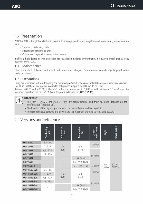
1.- PresentationPROPlus 3PH is the global electronic solution to manage positive and negative cold room stores, in combination with:
ŸStandard condensing units
ŸStreamlined condensing units
ŸOr as a service panel in decentralised systems.
It offers a high degree of IP65 protection for installation in damp environments. It is easy to install thanks to its new connection strip.
1.1.- MaintenanceClean the surface of the unit with a soft cloth, water and detergent. Do not use abrasive detergents, petrol, white spirits or solvents.
1.2.-
IMPORTANT:
ŸThe AUX 1, AUX 2 and AUX 3 relays are programmable, and their operation depends on the configuration (see page 25).
ŸThe function of the digital inputs depends on the configuration (See page 26).
ŸThe recommended currents and powers are the maximum working currents and powers.
2.- Versions and references
PrecautionsUsing the equipment without following the manufacturer's instructions may affect the device's safety requirements. To ensure that the device operates correctly, only probes supplied by AKO should be used. Between -40 ºC and +20 ºC, if the NTC probe is extended up to 1,000 m with minimum 0.5 mm² wire, the maximum deviation will be 0.25 ºC (Wire for probe extension ref. AKO-15586)
Co
nd
ensi
ng
unit
Co
nd
ense
rfa
ns
Evap
ora
tor
fan
Def
rost
re
sist
ance
s
Lig
ht
Pow
er s
up
ply
AKO-15690 2,5 - 4 A
3 A
(I+N)
4 A
(I+N)
7.000 W
1 A(230 W)
400 V / III50/60 Hz
AKO-15691 4 - 6,3 A
AKO-15692 6,3 - 10 A
10.200 WAKO-15693 10 - 16 A
AKO-15697- -
5 A (I+N)
AKO-15699 1.6 - 2.5 A (III+N)
AKO-15699-1 - - 6.3 - 10 A (I+N) 20.000 W
AKO-15690-EVC 2,5 - 4 A
3 A
(I+N)
4 A
(I+N)
7.000 WAKO-15691-EVC 4 - 6,3 A
AKO-15692-EVC 6,3 - 10 A
10.200 WAKO-15693-EVC 10 - 16 A
AKO-15697-EVC- -
5 A (I+N)
AKO-15699-EVC 1.6 - 2.5 A (III+N)
3
1569H042 Ed.02

1569H042 Ed.02
4
3.- Installation
90º
A.- Open and remove cover.
B.- Using the included template, make 4 holes in the wall and fasten the unit to the wall using the supplied screws. Make a hole in the bottom of the box to pass the cables through, and a suitable gland should be used to main the IP65 degree of protection.
355
255
1569H042 Ed.02
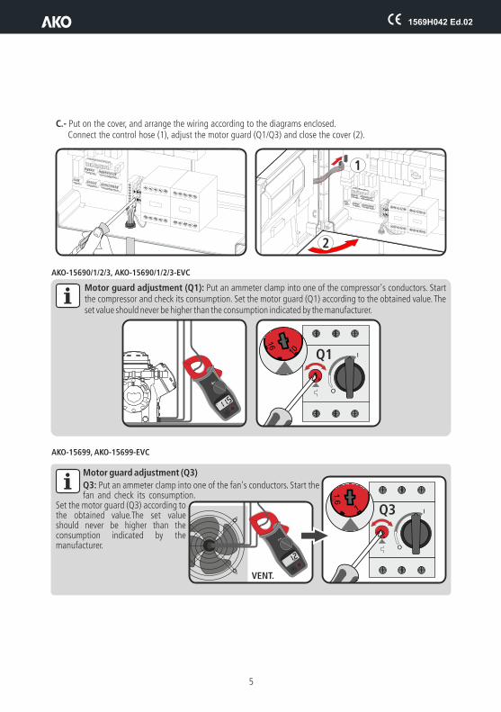
C.- Put on the cover, and arrange the wiring according to the diagrams enclosed.Connect the control hose (1), adjust the motor guard (Q1/Q3) and close the cover (2).
Motor guard adjustment (Q1): Put an ammeter clamp into one of the compressor's conductors. Start the compressor and check its consumption. Set the motor guard (Q1) according to the obtained value. The set value should never be higher than the consumption indicated by the manufacturer.
11.5
A
A
1
2
I
O
10
16
10
16
Q1
AKO-15690/1/2/3, AKO-15690/1/2/3-EVC
AKO-15699, AKO-15699-EVC
Motor guard adjustment (Q3)
Q3: Put an ammeter clamp into one of the fan's conductors. Start the fan and check its consumption.
Set the motor guard (Q3) according to the obtained value.The set value should never be higher than the consumption indicated by the manufacturer.
I
O
1
16
1
1.6
Q3
1.2A
A
VENT.
5
1569H042 Ed.02
A
BC
CC
6
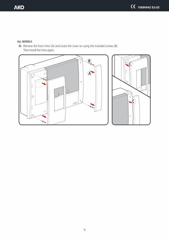
D.- Remove the front trims (A) and screw the cover on using the included screws (B).
Then install the trims again.
ALL MODELS

1569H042 Ed.02
7
4.- RecommendationsDisconnect the voltage before carrying out any operations inside the electrical panel. All wiring should be according to current standards and should be carried out by authorised staff. Only carry out the wiring foreseen in the wiring diagrams. Using the electrical panel not observing the manufacturer's instructions may alter the appliance's safety requirements. A tool is needed to remove any fixed part.Panel installation:It is advisable to leave a clean safety space without obstacles around the panel.Do not knock or make sudden movements on the panel.Carry out the wiring according to the installation manual.The probes and their cables should NEVER be installed in a conduit together with power, control or feeder cables.The earth terminals that the panels contain are installed to guarantee the continuity of earthing, however, earthing is not carried out by the terminal and should be carried out outside the panel.The neutral ratings are of the TT type. The IT rating should not be used.Circuit breakers (protective switches) are of the phase/s + neutral, curve C type, guaranteeing switching and protection against overcurrents.Close the panel when your are not working on it.Residual current protection outside the electrical panel according to low voltage electrotechnical regulations.The panels meet European standard EN 61439-1 / EN 61439-2.Terminals for copper external conductors.Checks before starting the panel up:Power supply voltages and frequencies will be the ones that figure in the "Technical specifications" section.Check that there are no loose parts or foreign bodies on connections or switchgear.Check that there is no dust or damp inside the panel.Check the correct fastening of the switchgear and components.Check the correct tightening of the screws and power connections.Check the correct connection of the power conductors.Check the correct insulation of the outer lines and that they do not mechanically force the inner connections of the panel.
Before starting the installation up, we recommend preheating the compressor's housing. Checks during the panel start-up:Check that no electric arcs occur.Check that the relays or contactors do not produce ratios.Check that there is no overheating in cables, controllers and the rest of the switchgear.Checks after the first 24 hours of operation:Check that no overheating occurs.Retighten screws and power connections.Periodical preventive maintenance:The panel should remain closed using its lock.Retighten the power connections once a year.Check the wear of the switchgear once a year.Clean the outer surface of the panel with a soft cloth, water and detergent. Do not use abrasive detergents, petrol, white spirits or solvents.Technical data:Working ambient temperature: –5 ºC to 40 ºCRated isolation voltage Ui = 440 V~Electrical panels with degree of protection: IP 65CEM B environmentTerminals for copper conductorsResistance to short-circuits Icc=6 kARated pulse voltage (Vimp) 2,5 KVCable isolation voltage:Operation: 500V (Halogen free)Power: 750V (Halogen free)
Check that the maximum current of the Q1 and Q3 current breaker (according to model) has been set correctly.

5.- Description
Electronicexpansion valve
controller
Defrosting in progressContinuous cycle active
Stand-by active mode
Change of the Set Point active (see page 13)
Cold room light activeAlarm active
Fans activeCompressor active*Compressor or solenoid active**
Temperatura
* If pump down is active, it indicates the operation of the compressor.
** If pump down is active, it indicates that the solenoid is open, otherwise it indicates that the compressor is in operation.
5.1.- Quick access to functions
?ESC
8
Display
Browser
Help key
Safety cover
Electrical protections
Escape key
Pressing it for 5 seconds allows changing the SET POINT temperature.
Pressing it for 5 seconds, activates or deacti-vates the CONTINUOUS CYCLE.
Pressing it for 5 seconds, the quick setup menu is accessed.
Pressing it for 2 seconds, activates or deacti-vates the cold room light (if P63=1). This function stays active although the unit is in the m mode.
Pressing it for 5 seconds activates or deactivates the defrost.
If probe 1 is displayed by default, the value of probe 2 will be displayed by pressing and vice versa. (see parameter P8)
Pressing it for 10 seconds, the advanced setup menu is accessed.
Silences the alarms (they are indicated on the display).
Pressing it for 5 seconds activates or deactivates the Stand-By mode. The display shows the m symbol in this mode.
SET
SET
SET
SET
SET
SET
1569H042 Ed.02

6.2- Messages
9
* Requires auxiliary alarm 2 to be configured as alarm relay (P62=1)
Flashing 0: Access code (Password) requestYou must enter the access code configured on L5 to execute the requested function (p. 19). See also parameter P2 (p. 25)
Probe 1 or 2 faulty(open circuit, crossover or temperature outside the probe limits; NTC: -50 To 99 ºC).(Activates alarm relay and sound alarm) *
Indicates a defrost is underway. When the defrost process has finished, the message will continue to be displayed during the time defined in parameter d3 (see Chapter 9.2).
Alternating with temperature:Maximum temperature in control probe alarm. Temperature set in A1 has been reached (p. 18) (Activates alarm relay and sound alarm) *
).
Alternating with temperature:Minimum temperature in control probe alarm. Temperature set in A2 has been reached (p.(Activates alarm relay and sound alarm) *
18
Alternating with temperature:External alarm activated (by digital input) (p. .(Activates alarm relay and sound alarm) *
18)
Alternating with temperature:Severe external alarm activated (by digital input) (p.(Activates alarm relay and sound alarm) *
18).
Alternating with temperature:Defrost alarm time-out. Displayed when a defrost ends after the maximum time elapsed as defined in parameter d1. (p.(Message only displayed on screen)
18).
Alternating with temperature:Door open alarm. Shown if the door remains open longer than specified in parameter A12 (p.(Activates alarm relay and sound alarm) *
18).
Alternating with temperature:The maximum pump down stop time has been exceeded (P15)(p. 18) (Message only displayed on screen)
Alternating with temperature:The maximum pump down start-up time has been exceeded (P14) (p. 19) (Message only displayed on screen)
It indicates that a component in the compressor's safety chain has triggered (compressor motor guard, thermistors or high pressure controller). (Pág. 19)
1569H042 Ed.02
1569H042 Ed.02
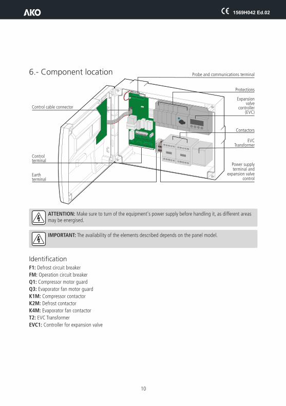
6.- Component location
ATTENTION: Make sure to turn of the equipment's power supply before handling it, as different areas may be energised.
IMPORTANT: The availability of the elements described depends on the panel model.
IdentificationF1: Defrost circuit breaker
FM: Operation circuit breaker
Q1: Compressor motor guard
Q3: Evaporator fan motor guard
K1M: Compressor contactor
K2M: Defrost contactor
K4M: Evaporator fan contactor
T2: EVC Transformer
EVC1: Controller for expansion valve
Probe and communications terminal
Protections
Expansionvalve
controller(EVC)
Contactors
EVCTransformer
Control cable connector
Control terminal
Earthterminal
Power supplyterminal and
expansion valvecontrol
10

1569H042 Ed.02
7.- Pressure switch wiring options
7
7
PE
PE6
6
9
9
LP HP
LP HP
7.- Pressure switch wiring options 7.- Pressure switch wiring options
Combine high-low pressure controller (AKO-15690/1/2/3 - AKO-15690/1/2/3-EVC)
Separate Low pressure controller per AC input (AKO-15690/1/2/3 - AKO-15690/1/2/3-EVC)
Pressure controller equivalence
HIGH / LOW
16 1617 17
1 A4 C
FAN CONTROL
DANFOS/ ALCO / RANCO PENN
7.- Pressure switch wiring options
6 69 97 7 7
21 22 114 4B 12 11 2
ALCO RANCO
6 9
A C
DANFOS/ PENN
11

12
8.- Basic configurationThe basic configuration menu allows the equipment to be configured for the most common applications. Press the SET key for 5 seconds to access it. If the access code is activated, a 2 digit code is requested (See page 19), if the code entered is not correct the unit will not enter programming.If more specific configuration is required use the advanced configuration menu (see page 22)After 20 seconds without touching any key, the unit returns to the previous level without saving changes or it will exit programming.
SP: Set point It defines the temperature that should be inside the cold storage room (See page 13):
ŸMinimum: –45.0 *
ŸMaximum: 99 *
*(Depends on the bottom/top locking of the set point).
Time that must elapse between the starting of each defrost (see page 15)
The defrost will end after this time has elapsed since it started.
It defines the status of the fans during defrost. 0= OFF 1= ON
Defines the temperature at which the maximum alarm will be triggered. Only affects probe 1.
ŸMinimum: –45.0 *
ŸMaximum: 99 *
*(Depends on the bottom/top locking of the set point).
Defines the temperature at which the minimum alarm will be triggered. Only affects probe 1.
ŸMinimum: –45.0 *
ŸMaximum: 99 *
*(Depends on the bottom/top locking of the set point).
Function of the keys in programming
d0: Defrost frequency
d1: Maximum defrost duration
F3: Fan status during defrost
A1: Maximum alarm probe 1
A2: Minimum alarm probe 1
Passes back to the previous parameter or decreases the value of the parameter.
Passes on to the next parameter or increases the value of the parameter.
Accesses the selected parameter or accepts the value.
Allows exiting a parameter without saving the changes or exiting programming.
SETSET
SETESC
1569H042 Ed.02

13
9.- Operation
9.1.- Compressor controlNORMAL OPERATION
CONTINUOUS CYCLE MODE
Use this function to cool the cold rooms before loading products.It is activate pressing the O key for 5 seconds, the display shows the % icon while this mode is active.
“CHANGE OF SET POINT” FUNCTION
Modifies the set point value in the low-use periods of the refrigeration device. If this variation is positive (increases the value), the display will show the ECO icon.
It can be activated after a certain time has elapsed (defined in parameter C11) without activity in the cold room door, to do this one of the digital inputs such as “door contact” (P10 or P11 = 1) must be configured.Optionally, you can activate and deactivate this mode at will, using an external pushbutton (1 press to activate/deactivate), configuring one of the digital inputs as “Change set point” (P10 or P11 = 4). If we set parameter C11 to 0, it can only be activated by external pushbutton.
ON
SP SP+Dif.
OFF
COMP.
ºC
When the temperature in probe 1 reaches the set point value (SP) plus the probe's differential (C1), the compressor activates and makes the temperature drop. When the set point value (SP) is reached, the compressor stops.
ON
SPC9 SP+C1OFF
COMP.
ºC
9.- Operation
9.1.- Compressor controlNORMAL OPERATION
CONTINUOUS CYCLE MODE
Use this function to cool the cold rooms before loading products.It is activate pressing the O key for 5 seconds, the display shows the % icon while this mode is active.
“CHANGE OF SET POINT” FUNCTION
Modifies the set point value in the low-use periods of the refrigeration device. If this variation is positive (increases the value), the display will show the ECO icon.
It can be activated after a certain time has elapsed (defined in parameter C11) without activity in the cold room door, to do this one of the digital inputs such as “door contact” (P10 or P11 = 1) must be configured.Optionally, you can activate and deactivate this mode at will, using an external pushbutton (1 press to activate/deactivate), configuring one of the digital inputs as “Change set point” (P10 or P11 = 4). If we set parameter C11 to 0, it can only be activated by external pushbutton.
When the temperature in probe 1 reaches the set point value (SP) plus the probe's differential (C1), the compressor activates and makes the temperature drop. When the set point value (SP) is reached, the compressor stops.
9.- Operation
9.1.- Compressor controlNORMAL OPERATION
CONTINUOUS CYCLE MODE
Use this function to cool the cold rooms before loading products.It is activate pressing the O key for 5 seconds, the display shows the % icon while this mode is active.
“CHANGE OF SET POINT” FUNCTION
Modifies the set point value in the low-use periods of the refrigeration device. If this variation is positive (increases the value), the display will show the ECO icon.
It can be activated after a certain time has elapsed (defined in parameter C11) without activity in the cold room door, to do this one of the digital inputs such as “door contact” (P10 or P11 = 1) must be configured.Optionally, you can activate and deactivate this mode at will, using an external pushbutton (1 press to activate/deactivate), configuring one of the digital inputs as “Change set point” (P10 or P11 = 4). If we set parameter C11 to 0, it can only be activated by external pushbutton.
Upon enabling this mode, the compressor starts up until the temperature of probe 1 reaches the set point value minus the change indicated in parame-ter C10.
The unit will then return to normal operation.
If this point is not reached, the unit returns to normal operation after the time set in C9, or by pressing the O key again for 5 seconds.
ON
SP+C12 (SP+C12)+C1
OFF
COMP.
ºC
Operation is the same as in the normal ode, but increasing the set point the amount of degrees defined in the C12 parameter.
1569H042 Ed.02

1569H042 Ed.02
14
COMPRESSOR PROTECTION DELAYThere are three types of delay, selectable by parameter C4, to protect the compressor. These delays prevent continuous compressor starts and stops due to sudden changes in temperature.
OFF-ON (C4=0): Minimum compressor OFF time before each start-up.OFF-ON / ON-OFF (C4=1): Minimum time during which the compressor will remain ON and OFF in every cycle.
The delay time is defined by parameter C5.
OPERATION IN CASE OF PROBE 1 FAILURE In the event of probe 1 failure (fault, disconnection, etc.) compressor performance will depend on C6 settings. Users may choose between 3 options:C6=0: The compressor will be stopped until probe 1 is working again.C6=1: The compressor will be operational until probe 1 is working again.C6=2: The compressor will operate according to the average performance of the last 24 hours, taking into
account the number of starts and stops and the average time in each state (stop-start).C6=3: The compressor will run as scheduled in C7 (ON) and C8 (OFF).
SET POINT LOCKINGUsing the C2 and C3 parameters, it is possible to set an upper and a lower limit for the Set point (SP), which precludes configuring a set point that is too low or too high that could damage the installation or the stored product.
STOP FANS AND COMPRESSOR WHEN THE DOOR IS OPENED
Parameter P23 defines whether the compressor stops when the cold room door is opened. To do so one of the digital inputs must be configured as "door contact" (P10 or P11=1) (See page 26).If the door stays open longer than the value programmed in parameter P24, the compressor will return to its normal operation.
ON ON
OFF-ON (C4=0) OFF-ON / ON-OFF (C4=1)
SP SPSP+C1 SP+C1
C5 C5C5
OFF OFF
COMP. COMP.
Time Time
ONProbe 1 error (If C6=3)
C8 C8C7 C7OFF
COMP.
Time
1569H042 Ed.02
15
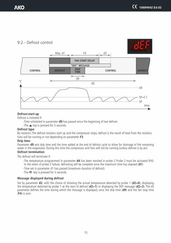
9.2.- Defrost control
Defrost start-upDefrost is initiated if:
-Time scheduled in parameter d0 has passed since the beginning of last defrost.-The N key is pressed for 5 seconds.
Defrost type
Drip timeParameter d9 sets drip time and the time added at the end of defrost cycle to allow for drainage of the remaining water in the evaporator. During this time the compressor and fans will not be running (unless defrost is by air).Defrost termination
The defrost will terminate if:
-The temperature programmed in parameter d4 has been reached in probe 2 Probe 2 must be activated (P4). In the event of probe 2 failure, defrosting will be complete once the maximum time has elapsed (d1)
-Time set in parameter d1 has passed (maximum duration of defrost).-The H key is pressed for 5 seconds.
Message displayed during defrost
Set by parameter d2, with the choice of showing the actual temperature detected by probe 1 (d2=0), displaying the temperature detected by probe 1 at the start of defrost (d2=1) or displaying the DEF message (d2=2). The d3 parameter defines the time during which the message is displayed, once the drip time (d9) and the fan stop time (F4) is over.
By resistors: The defrost resistors start up and the compressor stops; defrost is the result of heat from the resistors. Fans will be running or not depending on parameter F3.
CONTROL
time
ºC
F4Max. d1 d3
d9
d0
SP
SP+C1
d4
DEFROST DEFROSTDRIPTIME
FAN START DELAY
“DEF” MESSAGE
CONTROL CONTROL
1569H042 Ed.02
16
Other parameters
Parameter d5 allows users to specify if the unit will (d5=1) or will not (d5=0) defrost when powered up (initial start-up or after a power failure). In case of choosing option YES (d5=1), the defrost will start after the delay time specified in d6.
Using parameter d8, users define the computation of time in d0, choosing between total time elapsed (d8=0) or the total compressor running time (d8=1).
NOTE: If parameter d1 is set to 0, no defrost will be performed.
Remote defrost
This function allows activating the defrost of the unit using an external button, connecting it to one of the digital inputs that must be configured as "remote defrost”(P10 ó P11=6) .
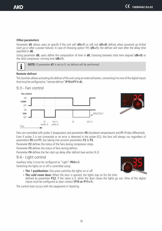
9.3.- Fan control
Fans are controlled with probe 2 (evaporator) and parameters F0 (shutdown temperature) and F1 (Probe differential).
Even if probe 2 is not connected or an error is detected in the probe (E2), the fans will always run regardless of parameters F0 and F1, but taking into account parameters F2 to F5.
Parameter F2 defines the status of the fans during compressor stops.
Parameter F3 defines the status of fans during defrost.
Parameter F4 defines the fan start-up delay after defrost (see section 9.2)
9.4.- Light controlAuxiliary relay 3 must be configured as “Light” (P63=1).
Switching the lights on or off is controlled using:
ŸThe ? pushbutton: One press switches the lights on or off.
ŸThe cold room door: When the door is opened, the lights stay on for the time defined by parameter P22. If the value is 0, when the door closes the lights go out. (One of the digital inputs must be configured as door contact (P10 or P11=1).
The control even occurs with the equipment in Stand-by.
ON
ON
Fan control
SPF0(probe 2)
F0+F1probe 2)
Only if F2=1
SP+C1
OFF
OFF
COMP.
FAN
Time
Other parameters
Parameter d5 allows users to specify if the unit will (d5=1) or will not (d5=0) defrost when powered up (initial start-up or after a power failure). In case of choosing option YES (d5=1), the defrost will start after the delay time specified in d6.
Using parameter d8, users define the computation of time in d0, choosing between total time elapsed (d8=0) or the total compressor running time (d8=1).
NOTE: If parameter d1 is set to 0, no defrost will be performed.
Remote defrost
This function allows activating the defrost of the unit using an external button, connecting it to one of the digital inputs that must be configured as "remote defrost”(P10 ó P11=6) .
9.3.- Fan control
Fans are controlled with probe 2 (evaporator) and parameters F0 (shutdown temperature) and F1 (Probe differential).
Even if probe 2 is not connected or an error is detected in the probe (E2), the fans will always run regardless of parameters F0 and F1, but taking into account parameters F2 to F5.
Parameter F2 defines the status of the fans during compressor stops.
Parameter F3 defines the status of fans during defrost.
Parameter F4 defines the fan start-up delay after defrost (see section 9.2)
9.4.- Light controlAuxiliary relay 3 must be configured as “Light” (P63=1).
Switching the lights on or off is controlled using:
ŸThe ? pushbutton: One press switches the lights on or off.
ŸThe cold room door: When the door is opened, the lights stay on for the time defined by parameter P22. If the value is 0, when the door closes the lights go out. (One of the digital inputs must be configured as door contact (P10 or P11=1).
The control even occurs with the equipment in Stand-by.

1569H042 Ed.02
17
9.5.-
Pump down function This function prevents compressor problems caused by movement of the refrigerant, using a stop/start technique of the unit controlled by liquid solenoid, the low pressure switch and the compressor.
For this feature to be active, the auxiliary relay must be set as "Pump down" (P6=1).
SHUTOFF
When temperature probe 1 reaches the set point value (SP), the AUX 1 relay is deactivated by closing the liquid solenoid.
Since the compressor is still running the evaporator pressure drops suddenly. When it reaches a specific point, the low pressure switch is activated, changing the state of digital input 1, and the controller stops the compressor.
This manoeuvre isolates the refrigerant from the compressor crankcase, preventing serious damage on start-up.
In case of low pressure switch failure, the controller stops the compressor after the safety time set at P15, showing the message "Pd", but it will continue to function normally. (informative message, does not affect the equipment operation).
If time P15 is 0 (default value), the compressor will not stop until the low pressostat is activated, but it will display the “Pd” message after 15 minutes.DOES NOT activate the alarm relay or the sound alarm, it is only shown on the display.
STARTUP
When temperature probe 1 reaches the set point value plus the differential (SP+C1), the AUX 1 relay is activated (ON), opening the liquid solenoid. This causes the pressure in the evaporator to increase, disabling the low pressure switch. The controller detects this change and starts the compressor.
If a period of time has elapsed (determined by P14) after the liquid solenoid is opened (AUX 1 relay set to ON), the low pressostat will not be deactivated, the controller will once again close the solenoid (AUX 1 relay set to OFF) and the “LP” message will be displayed. This manoeuvre will be repeated every 2 minutes indefinitely until the pressostat is deactivated and the installation reverts to its normal operation.If time P14 is 0 (default value), the solenoid will stay open until the low pressostat is deactivated, but it will display the “LP” message after 3 minutes.DOES NOT activate the alarm relay or the sound alarm, it is only shown on the display.
STAND-BY
If the pump-down function is active, some time may elapse from the time the stand-by function starts until the controller stops. This is because certain control phases of the system cannot be stopped.
ONLiquid solenoid
Low pressure switch
Pressure switch fault
Pressure switch fault
Compressor
Evaporator pressure
ON
ON
+
P15 P14
OFF
OFF
OFF
AUX 1
DigitalInput
COMP.
Time SP SPSP+C1 SP+C1

1569H042 Ed.02
18
9.6.- AlarmsThe unit warns the user with a message on the screen of the activation of a relay or the activation of an acoustic signal in certain circumstances, according to the programming of the following parameters.
Max/Min Temperature Alarm
Shows the AH or AL message when the temperature in probe 1 reaches the value set in the A1 (maximum temperature) or A2 (low temperature) parameters.
This value can be:
Absolute (A0=1): A1/A2 should indicate the temperature at which the alarm should be activated.
Relative to SP (A0=0): A1/A2 should indicate the number of degrees above or below the set point at which the alarm is activated. This option allows users to adjust the set point without having to modify the high and low alarm settings.
Parameter A10 sets the differentials for both parameters (hysteresis).
Activates alarm relay (if P62=1) and sound alarm.
Example
In a controller we configure the following parameters: SP=2, A1=10, A10=2
- If A0=0 (relative to SP), the maximum temperature alarm goes off when probe 1 reaches 12 degrees and is disabled when it reaches 10 degrees.
- If A0=1 (absolute), the maximum temperature alarm goes off when probe 1 reaches 10 degrees and is disabled when it reaches 8 degrees.
External alarm/severe external alarm
Displays the message AE (external alarm) or AES (severe external alarm), when the digital input configured as external alarm or severe external alarm is activated.
The severe external alarm also deactivates all the charges, therefore, the temperature regulation is stopped. When this alarm disappears the device returns to its normal operation.
At least one of the digital inputs must be configured as external alarm (P10 or P11=2) or severe external alarm (P10 or P11=3).
Activates alarm relay (if P62=1) and sound alarm.
Defrost alarm completed by time.
Shows the Adt alarm message when a defrost terminates by time-out, if parameter A8=1.
DOES NOT activate the alarm relay or the sound alarm, it is only shown on the display.
Door open alarm Displays the PAb message when the door stays open for a time greater than that set with parameter A12. (One of the digital inputs must be configured as door contact (P10 or P11=1).Activates alarm relay (if P62=1) and sound alarm.
Pump down malfunction error (Stop)Displays the Pd message if a malfunction is detected when the installation is stopped using the pump down manoeuvre. (See page 17).DOES NOT activate the alarm relay or the sound alarm, it is only shown on the display.
1569H042 Ed.02
19
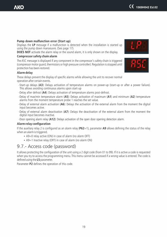
Pump down malfunction error (Start up)Displays the LP message if a malfunction is detected when the installation is started up using the pump down manoeuvre. (See page 17).DOES NOT activate the alarm relay or the sound alarm, it is only shown on the display.
Compressor safety chain alarm
The ASC message is displayed if any component in the compressor's safety chain is triggered (compressor motor guard, thermistors or high pressure controller). Regulation is stopped until protection has been restored.
Alarm delay
These delays prevent the display of specific alarms while allowing the unit to recover normal operation after certain events.
-Start-up delays (A3): Delays activation of temperature alarms on power-up (start-up or after a power failure). This allows avoiding continuous alarms upon start-up
-Delay after defrost (A4): Delays activation of temperature alarms post-defrost.
-Delay of max/min temperature alarm (A5): Delays activation of maximum (A1) and minimum (A2) temperature alarms from the moment temperature probe 1 reaches the set value.
-Delay of external alarm activation (A6): Delays the activation of the external alarm from the moment the digital input becomes active.
-Delay of external alarm deactivation (A7): Delays the deactivation of the external alarm from the moment the digital input becomes inactive.
-Door opening alarm relay (A12): Delays activation of the open door opening detection alarm.
Alarm relay configuration
If the auxiliary relay 2 is configured as an alarm relay (P62=1), parameter A9 allows defining the status of the relay when an alarm is triggered.
ŸA9=0 relay active (ON) in case of alarm (no alarm OFF)
ŸA9=1 Inactive relay (OFF) in case of alarm (no alarm ON)
9.7.- Access code (password)It allows protecting the configuration of the unit using a 2 digit code (from 01 to 99). If it is active a code is requested when you try to access the programming menu. This menu cannot be accessed if a wrong value is entered. The code is defined using the L5 parameter.
Parameter P2 defines the operation of this code.

1569H042 Ed.02
20
10.- Parameter transferThis function allows transferring the programmed parameters from one device to others, using the AKO-D14918 programming key. This will save a lot of time when configuring similar devices.Requires the use of the AKO-80018 power supply for the programming key.
Transfer parameters from the equipment to the key
žDisconnect the unit power supply.
žConnect the programming key in the parameter server connector.
žConnect the power supply for the programming key.
žPress the READ key on the programming key.
žDisconnect the device programming key.
Transfer parameters from the key to the equipment
žDisconnect the unit power supply.
žConnect the programming key in the parameter server connector.
žConnect the power supply for the programming key.
žPress the RECORD key for the programming key.
žDisconnect the device programming key.
AKO-80018
AKO-D14918
LED ON
LED COM
Connection cable
ReadKey
RecordKey
ExternalPower Supply
Connector
1569H042 Ed.02
21
*If over 31 units are connected, use an AKO-80024 connector.
ESC ?
SET
ESC ?
SET
A-
A-
B+
B+
A-
A-
B+
B+
GND
GND
GND
GND
GND
+12V
CAMRegis
PROPlus 3PHAKO-156xx
PROPlus/PROPlus BASIC
AKO-80024* repeater
AKO-80039 converter
Amarillo
Rojo
Negro
PC with AKONet
(AKO-5010)
GND
Tr-Tr-Tr-
B
Tr+Tr+Tr+
AKO-5011web server
orLAN
A
Gnd
Gnd
+RS-4
85
GN
D
CAMAlarm/COMBIAlarm AKO-D146xx-C
ºC
ºF
AKO-DARWIN controller with
built-in communication
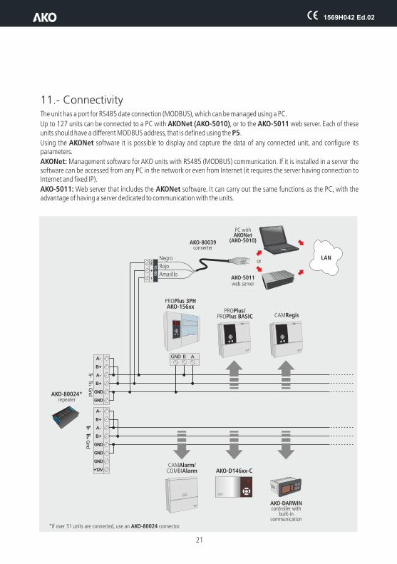
11.- ConnectivityThe unit has a port for RS485 date connection (MODBUS), which can be managed using a PC.
Up to 127 units can be connected to a PC with AKONet (AKO-5010), or to the AKO-5011 web server. Each of these units should have a different MODBUS address, that is defined using the P5.
Using the AKONet software it is possible to display and capture the data of any connected unit, and configure its parameters.
AKONet: Management software for AKO units with RS485 (MODBUS) communication. If it is installed in a server the software can be accessed from any PC in the network or even from Internet (it requires the server having connection to Internet and fixed IP).
AKO-5011: Web server that includes the AKONet software. It can carry out the same functions as the PC, with the advantage of having a server dedicated to communication with the units.
1569H042 Ed.02
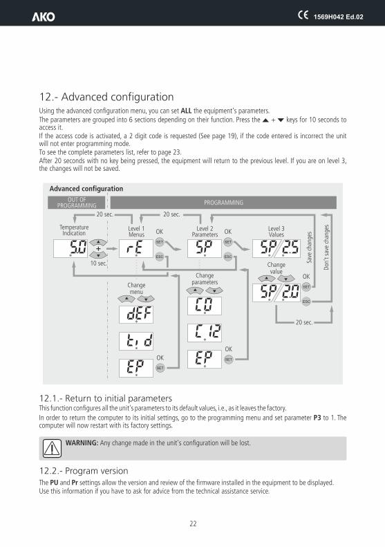
12.- Advanced configurationUsing the advanced configuration menu, you can set ALL the equipment's parameters.The parameters are grouped into 6 sections depending on their function. Press the N + Q keys for 10 seconds to access it. If the access code is activated, a 2 digit code is requested (See page 19), if the code entered is incorrect the unit will not enter programming mode.To see the complete parameters list, refer to page 23.After 20 seconds with no key being pressed, the equipment will return to the previous level. If you are on level 3, the changes will not be saved.
12.1.- Return to initial parametersThis function configures all the unit's parameters to its default values, i.e., as it leaves the factory.
In order to return the computer to its initial settings, go to the programming menu and set parameter P3 to 1. The computer will now restart with its factory settings.
WARNING: Any change made in the unit's configuration will be lost.
12.2.- Program versionThe PU and Pr settings allow the version and review of the firmware installed in the equipment to be displayed. Use this information if you have to ask for advice from the technical assistance service.
22
SET SET
SET
SET
SET
Advanced configuration
Level 2Parameters
Changeparameters
Level 3Values
Save
cha
nges
Don
’t s
ave
chan
ges
OK
20 sec.
20 sec.20 sec.
OKOK
OK
OK
Changevalue
Level 1Menus
Changemenu
TemperatureIndication
10 sec.
OUT OF PROGRAMMING PROGRAMMING
ESC ESC
ESC
1569H042 Ed.02
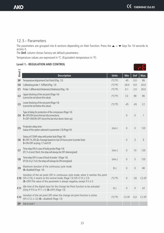
12.3.- ParametersThe parameters are grouped into 6 sections depending on their function. Press the N + Q keys for 10 seconds to access it. The Def. column shows factory-set default parameters.
Temperature values are expressed in ºC. (Equivalent temperature in ºF)
Level 1.- REGULATION AND CONTROL
Description Units Min Def Max.
SP Temperature Adjustment (Set Point) (Pág. 13) (ºC/ºF) -45 0.0 99
C0 Calibrating probe 1 (Offset) (Pág. 13) (ºC/ºF) -20.0 0.0 20.0
C1 Probe 1 differential (Histeresis) (Histéresis) (Pág. 14) (ºC/ºF) 0.1 2.0 20.0
C2Upper blocking of the set point (Page 14)(cannot be set above this value)
(ºC/ºF) C3 99 99
C3Lower blocking of the set point (Page 14)(cannot be set below this value)
(ºC/ºF) -45 -45 C2
C4Type of delay for protection of the compressor (Page 14)0=OFF/ON (since the last disconnection); 1=OFF-ON/ON-OFF (since the last shut-down /start-up)
0 0 1
C5Protection delay time(value of the option selected in parameter C4) (Page14)
(min.) 0 0 120
C6Status of COMP. relay with probe fault (Page 14):0=OFF; 1=ON; 2=Average based on last 24 hours prior to probe fault; 3=ON-OFF as prog. C7 and C8
0 2 3
C7Time relay ON in case of faulty probe (Page 14):
(If C7=0 and C8¹0, the relay will always be OFF deenergised)(min.) 0 10 120
C8Time relay OFF in case of fault of probe 1 (Page 14):
(If C8=0 y C7¹0, the relay will always be ON energised)(min.) 0 5 120
C9Maximum duration of the continuous cycle mode. (0=disabled) (Page. 14)
(h.) 0 0 48
C10Variation of the set point (SP) in continuous cycle mode, when it reaches this point (SP+C10), it reverts to the normal mode. (Page 13) (SP+C10 ³ C3) (0=OFF) The value of this parameter is always negative, except if it is 0
(ºC/ºF) 0 -50 C3-SP
C11Idle time of the digital input for the change Set Point function to be activated(Only if P10 or P11 =1) (0=OFF) (Page 13)
(h.) 0 0 24
C12Variation of the set point (SP) when the change set point function is active.
(SP+C12 £ C2) (0= disabled) (Page 13)(ºC/ºF) C3-SP 0,0 C2-SP
EP Exit to Level 1
Niv
el 2
23

1569H042 Ed.02
24
Description Units Min Def Max.
d0 Defrost frequency (Time between two starts) (Page 15) (h.) 0 6 96
d1 Maximum defrost duration (0=defrost deactivated) (Page 15 ) (min.) 0 15 255
d2Type of message during defrost: (Page 15)0=Current temperature; 1=Temperature at start of defrost; 2=Display dEF message
0 2 2
d3Maximum duration of message (Time added at the end of the defrost process) (Page15)
(min.)0 5 255
d4 Defrost end temperature (probe 2) (If P4 ¹ 1) (Page. 15) (ºC/ºF) -45 8.0 99,0
d5Defrost on equipment start-up (Page16):0=NO, First defrost as per d01=YES, First defrost as per d6
0 0 1
d6 Defrost start delay on equipment start-up (Page 16) (min.) 0 0 255
d8Calculated time between defrost period (Page 16):0=Total actual time; 1 =Sum of times the compressor is on
0 0 1
d9Drip time at end of defrost (Page 15)
(compressor and fans off) (if P4 ¹ 1)(min.) 0 1 255
EP Exit Level 1
Level 1.- DEFROST CONTROL
Leve
l 2
Description Units Min Def Max.
F0Fan shut-down temperature as per probe 2
(if P4 ¹ 1) (Page 16)(ºC/ºF) -45 45 99,0
F1 Probe 2 differential (If P4 ¹ 1) (Page16) (ºC/ºF) 0,1 2,0 20,0
F2 Stop fans when stopping compressor 0=No, 1=Yes (Page 16) 0 1 1
F3Fan status during defrost: (Page 16)0=Off; 1=On
0 0 1
F4Starting delay after defrost (if F3=0) (Page 16)Will only operate if it is higher than d9
(min.) 0 3 99
EP Exit Level 1
Leve
l 2
Level 1.- FAN CONTROL

1569H042 Ed.02
* See table page 26.
**The options available in each setting can vary depending on the model.
Level ALARM CONTROL 1.-
Level GENERAL STATUS 1.-
25
Description Units Min Def Max.
A0 Configuration of temperature alarms (Page 18): 0=Relative to SP 1=Absolute 0 1 1
A1 Maximum alarm probe 1 (must be greater than SP) (Page 18) (ºC/ºF) A2 99,0 99,0
A2 Minimum alarm probe 1 (must be greater than SP) (Page 18) (min.) -45 -45 A1
A3 Temperature alarm delay during start-up (Page 19) (min.) 0 0 120
A4 Temperature alarm delay after completion of a defrost (Page 19) (min.) 0 0 99
A5 Temperature alarm delay after reaching the value of A1 or A2 (Page 19) (min.) 0 30 99
A6 External alarm delay when receiving digital input signal (P10 or P11=2 or 3) (Page 19) (min.) 0 0 120
A7Deactivation delay of the external alarm when the signal of the digital input disappears (P10 or P11=2 or 3) (Page 19)
(min.) 0 0 120
A8 Show warning if defrost is terminated by time-out 0=No, 1=Yes (Page 18) 0 0 1
A9Alarm relay polarity 0= Relay ON in alarm (OFF no alarm);(Page 19) 1= Relay OFF on alarm (ON with no alarm)
0 0 1
A10 Temperature Alarm Differential (A1 and A2) (Page 18) (ºC/ºF) 0,1 1,0 20,0
A12 Door open alarm delay (if P10 or P11=1) (Page 19) (min.) 0 10 120
EP Exit Level 1
Leve
l 2
Description Units Min Def Max.
P1 Delay of all functions on receiving electrical power (min.) 0 0 255
P2Función del código de acceso (password) 0= Inactivo; 1= Bloqueo acceso a parámetros; 2= Bloqueo del teclado
0 0 2
P3Configures the default factory settings 0= No changes 1=Return to default settings
0 0 1
P4 Selection of type of inputs 1=1 probe 2=2 probes 1 2 2
P5 MODBUS address (Page 21) 1 1 225
P6AUX 1 relay configuration** 0=Deactivated1=Pump down 2= Same compressor status
0 * 2
P62AUX 2 relay configuration** 0=Deactivated 1=Alarm
2= Same compressor status 3=Same unit status 4=Pump down0 * 4
P63AUX 3 relay configuration** 0=Deactivated 1=Light
2=Same unit status0 1 2
P7Temperature display mode
0=Integers in ºC 1=One decimal in ºC 2=Integers in ºF 3=One decimal in ºF
0 1 3
P8Probe to be displayed (as per parameter P4)
0=visualization of all the probes in sequence; 1=Probe 1 2=Probe 20 1 2
Leve
l 2
1569H042 Ed.02
Nivel 1.- (tid)ACCESS CONTROL AND INFORMATION
26
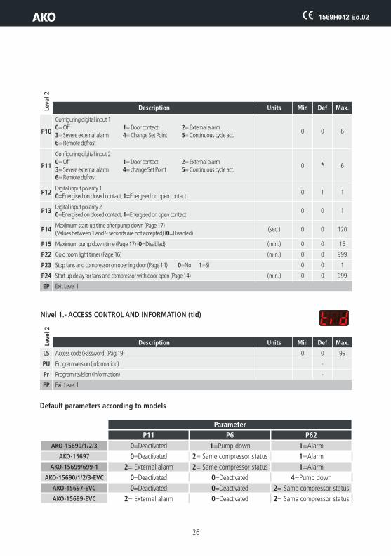
Description Units Min Def Max.
P10
Configuring digital input 10= Off 1= Door contact 2= External alarm3= Severe external alarm 4= Change Set Point 5= Continuous cycl6= Remote defrost
e act.0 0 6
P11
Configuring digital input 20= Off 1= Door contact 2= External alarm3= Severe external alarm 4= change Set Point 5= Continuous cycl6= Remote defrost
e act.0 * 6
P12Digital input polarity 10=Energised on closed contact, 1=Energised on open contact
0 1 1
P13Digital input polarity 20=Energised on closed contact, 1=Energised on open contact
0 0 1
P14Maximum start-up time after pump down (Page 17)(Values between 1 and 9 seconds are not accepted) (0=Disabled)
(sec.) 0 0 120
P15 Maximum pump down time (Page (0=Disabled) 17) (min.) 0 0 15
P22 Cold room light timer (Page 16) (min.) 0 0 999
P23 Stop fans and compressor on opening door (Page 14) 0=No 1=Si 0 0 1
P24 Start up delay for fans and compressor with door open (Page 14) (min.) 0 0 999
EP Exit Level 1
Description Units Min Def Max.
L5 Access code (Password) (Pág 19) 0 0 99
PU Program version (Information) -
Pr Program revision (Information) -
EP Exit Level 1
Leve
l 2
Leve
l 2
Default parameters according to models
Parameter
Modelos P11 P6 P62
AKO-15690/1/2/3 0=Deactivated 1=Pump down 1=Alarm
AKO-15697 0=Deactivated 2= Same compressor status 1=Alarm
AKO-15699/699-1 2= External alarm 2= Same compressor status 1=Alarm
AKO-15690/1/2/3-EVC 0=Deactivated 0=Deactivated 4=Pump down
AKO-15697-EVC 0=Deactivated 0=Deactivated 2= Same compressor status
AKO-15699-EVC 2= External alarm 0=Deactivated 2= Same compressor status
1569H042 Ed.02
27
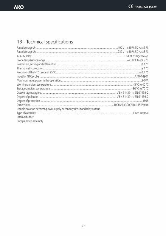
13.- Technical specificationsRated voltage Un...........................................................................................................400 V~ ±10 % 50 Hz ±5 %
Rated voltage Ue...........................................................................................................230 V~ ±10 % 50 Hz ±5 %
ALARM relay ........................................................................................................................... 8A at 250V, cosj=1
Probe temperature range...........................................................................................................–45.0 ºC to 99.9 ºC
Resolution, setting and differential ................................................................................................................0.1 ºC
Thermometric precision.................................................................................................................................± 1 ºC
Precision of the NTC probe at 25 ºC .............................................................................................................± 0.4 ºC
Input for NTC probe .............................................................................................................................AKO-14901
Maximum input power in the operation ..........................................................................................................30 VA
Working ambient temperature............................................................................................................-5 ºC to 40 ºC
Storage ambient temperature ..........................................................................................................–30 ºC to 70 ºC
Overvoltage category.................................................................................................II s/ EN 61439-1 / EN 61439-2
Degree of pollution ....................................................................................................II s/ EN 61439-1 / EN 61439-2
Degree of protection .......................................................................................................................................IP65
Dimensions .............................................................................................................400(An) x 300(Al) x 135(P) mm
Double isolation between power supply, secondary circuit and relay output.
Type of assembly................................................................................................................................Fixed internal
Internal buzzer
Encapsulated assembly

351569042 REV
.01 2
015
We reserve the right to supply materials that might vary slightly to those described in our Technical Sheets. Updated information is available on our website.
AKO ELECTROMECÁNICA , S.A.L.
Avda. Roquetes, 30-3808812 Sant Pere de Ribes.Barcelona Spain.
Tel.: +34 902 333 145Fax: +34 938 934 054www.ako.com
••