proportional directional spool valve type pslf, psvf, and ... · pdf fileher, separately...
TRANSCRIPT

2.1
Proportional directional spool valve type PSLF, PSVF, and SLFaccording to the Load-Sensing principlesize 3 and 5 (manifold mounting)
D 7700-FProp. directional spool
valve PSLF, PSVF and SLF
August 2008-02
HAWE HYDRAULIK SESTREITFELDSTR. 25 • 81673 MÜNCHEN
© 1998 by HAWE Hydraulik
1. General information.......................................1
2. Type coding, overview ..................................2
3. Available version, main data ........................43.1 Connection blocks and end plates ....................................43.2 Add-on spool valves ..........................................................8
4. Characteristic data ......................................144.1 General and hydraulic ......................................................144.2 Curves ..............................................................................154.3 Actuations ..........................................................................164.4 Functional cut-off, prop. pressure limitation.......................194.5 Other solenoid valves....................................................... 20
5. Unit dimensions.............................................215.1 Size 3...............................................................................21 5.2 Size 5.............................................................................30
6. Appendix ......................................................416.1 Notes for selection and lay-out ........................................416.2 Circuit examples ...............................................................456.3 Notes regarding assembly, installation and conversion .....45
1. General information The directional spool valves types PSLF and PSVF as wellas the individual sections type SLF serve to control both, thedirection of movement and the load-independent, steplessvelocity of the hydraulic consumers. In this way several con-sumers may be moved simultaneously, independently fromeach other at different velocity and pressure ratings, as longas the sum of the partial flows needed for this is within thetotal delivery supplied by the pump. The proportional spool valves of this pamphlet are designedas manifold mounting valves. They may be also combinedas valve banks via the sub-plates available from HAWE.They consist of three functional groups:
Basic dataDesign Prop. directional spool valve according to the
Load-Sensing principleVersions Individual valves and valve banks (manifold
mounting)Operating pressure pmax 420 bar Flow Qmax 80 (120) lpm (Size 3)
Qmax 160 (240) lpm (Size 5)
Further technical information:Size DesignSize 2 (valve bank design) D 7700-2 Size 3 (valve bank design) D 7700-3Size 5 (valve bank design) D 7700-5
<<
;;
Mounting
;; Inlet section(control section)
<< Size 5 (valve bank design)
== End plate
>> Sub-plates
==
Table of contents
>>

D 7700 F page 2
2. Type coding, overview
Valve section (for individual orders, without sub-plate) Inlet section (for individual order, without sub-plate)
SLF 3 - A2 J 25/16 C300 / EA - G 24 PSLF A H1 F80 / 400 - 3 - G 24
1613121110987 5431 1671
1615141312111098765432
2+
Valve bank
PSLF A H1 F80 / 400 /4 - 3 - A2 J 25/16 C300 /EA /3 AN320 BN320- A2 D 80/63 F1 /EA /3 - E4 - G 24
1
Order examples:
;; Basic type coding for the valve bank or inlet section (see table1 and 5 in sect. 3.1.1 and 3.1.2) as well as valve sections (see sect. 3.2)
PSLF A Supply with pressurized oil by means of fixed pump (open center)
PSVF A Supply with pressurized oil by means of variable displacement pump (closed center)with a delivery flow controller, or as a second,separate unit if both valve banks are connec-ted to a constant pressure system
SLF Individual valve section, without sub-plate
<< Additional elements (see table 2 and 6 in sect. 3.1.1 and 3.1.2)(no coding) Basic version S, W Additional damping device in gallery LS (only
with PSVF, standard with PSLF)B, B 4 ... B 7 Orifice in gallery LS (PSVF only)G Restrictor check valve (type PSLF)H Raised circulation pressure of the 3-way flow
controller (approx. 14 bar with type PSLF)
== Control oil supply (see table 7, sect. 3.1.3)(no coding) Without pressure reducing valve in case of
an external control oil supply (min. 20 bar upto max. 40 bar)
1 With integrated pressure reducing valve forthe internal supply of control oil (control pres-sure approx. 20 bar)
2 With integrated pressure reducing valve forthe internal supply of control oil (control pres-sure approx. 40 bar)
>> Optional 2/2-way solenoid valve for arbitrary idle pump circu-lation (see table 8, sect. 3.1.3)(no coding) Without directional valve, but prepared for
retrofittingF, Z, ZM De-energized open = Idle pump circulation
when valve is de-energized D, V De-energized closed = Idle pump circulation
when valve is energized F.. or D.. When a pressure is specified, with pressure
limiting valve which can be activated as asecond pressure stage (e.g. F 50)
PA, PB, PD Prop. pressure limiting valve, with variouspressure ranges
?? Pressure limiting valve (main pressure limitation) in the inletsection (see table 9, sect. 3.1.3)(no coding) Without pressure limiting valve (type PSVF
only)/ ... Pressure limiting valve factory set to ... bar
@@ Sub-plate for the inlet section (see table 3, sect. 3.1.1 )/4, /UNF 4 Size 3, standard (tapped ports for P and R
G 3/4 DIN ISO 228/1 (BSPP) (BSPP) or 11/16-12 UN-2B SAE J 514)
/6 Size 5, standard (tapped ports for P and RG 1 1/4 DIN ISO 228/1 (BSPP) (BSPP))
/7 SAE Size 5 (flange SAE 1 1/2” 6000 psi)
AA Size (see table 1 and 5, sect. 3.1.1 and 3.1.2)3 or 5 Various connection hole pattern (adapter
plates enabling direct mounting between size 5 and 3 with type ZPL 53 see table 10,sect. 3.1.4)
BB Valve section - Basic function (see table 12, section 3.2.1)A 2 (standard) Spool valve with inflow controller for each
consumer A 1 Spool valve without inflow controller, suitable
for consumers, which are actuated individual-ly and successively but not simultaneously (no additional functions possible)
A 5, A 7 Inflow controller with enforced spring for higher flow
A 8 4/3-way directional spool valve (pre-selectorvalve)
AR 2, AR 5, like A 2, A 5, A 7 but with check valve AR 7 functionAX Blanking plate
CC Coding for the flow-pattern (see table 14, sect. 3.2.1 and 6 c) L, M, F, H, J, B, R, O, P, A, Q, K, T, I, Y, Z, V, G, W, X
DD Flow coding for port A and B (see table 15, sect. 3.2.1).../... Coding for port A or B (independently selec-
table)3, 6, 10, 16, 25, 40, 63, 80 (size 3)16, 25, 40, 63, 80, 120, 160 (size 5)
EE Secondary pressure limitation (deviating from the main pressure setting, lower pressure for the connected consumer)no shock valves (see table 15 and 17, section 3.2.1) (doesn'tapply to spool valve types without inflow controller, coding A 1 BB or table 12)(no coding) No secondary pressure limitationA..., B... Only for consumer port or BA...B... For consumer ports A and BC... Joint for consumer port A and B (not in con-
junction with coding F.. or S FF )
D 7700 F page 3
FF unctional cut-off (see table 16 and 17, sect. 3.2.1) (doesn't apply to spool valve types without inflow controller,coding A1 BB or table 12)(no coding) No functional cut-off F 1 Electrical cut-off, consumer port AF 2 Electrical cut-off, consumer port B F 3 Electrical cut-off, consumer port A and B FP 1(2, 3) Like F1(2,3), however with electro-proportio-
nal pressure limitationFPH 1(2, 3) Like FP1(2,3), however with additional push-
button for manual emergency actuationS, S 1 External hydraulic load signal pick-up from the
control signal port U (consumer port A) and W(consumer port B)
GG Types of actuation (see table 18 and19, sect. 3.2.1)/A (1,2) Manual actuation
(suffix 1 = without hand lever, 2 = short lever)/E Electro-hydraulic actuation/EA (1,2) Electro-hydraulic and manual actuation (suf-
fix 1 = without hand lever, 2 = short lever)/E0A (1,2) Like /EA(1,2), however without actuation sole-
noid (prepared for retrofitting) (suffix 1 = without hand lever, 2 = short lever)
/H, /HA (1,2), Hydraulic without or with manual actuation/F, /FA/HEA (1,2) Hydraulic, solenoid and manual actuation/C (1,2), AC(1,2)Detent (stepless) /EC, /EAC Electrical detent without or with manual
actuation/P, /PA (1,2) Pneumatic actuation without or with manual
actuation/... Suffix G Reinforced version
N (1) Proximity switchV, VA, VB, VC, Contact switch monitoringVCHO, VCHC, the spool elevationVCHOCB Solenoid with quarter-turn type plugWA, WA-EX n Displacement transducer U Lift monitoring (side indication) T, BT Manual emergency actuationTH Manual emergency actuation with
pushbutton
HH Sub-plate for the individual valve section (see table 20, section 3.2.2)/3.. = G 1/2 (ISO 228/1 (BSPP)) /4.. = G 3/4 (ISO 228/1 (BSPP))/5.. = G 1 (ISO 228/1 (BSPP))/UNF 3.. = 7/8-14 UNF-2B (SAE-10)/UNF 4.. = 1 1/16-12 UN-2B acc. to SAE J 514)
/3, /4, Size 3 /UNF 3, /UNF 4/38, /58 Size 3 or 5, sub-plate for pre-selec-
tor valve function/3 AN.. BN.. Size 3, shock and suction valves at A /UNF 3 AN.. BN.. or B together with pressure specifica-
tion/3 AN.., /3 BN.., Size 3, shock and suction valves at A /UNF 3 AN.., or B together with pressure /UNF 3 BN.. specification/3 A..B.. Size 3, shock valve at A and B
together with pressure specification/3 A.., /3 B.. Size 3, shock valve at A or B
together with pressure specification
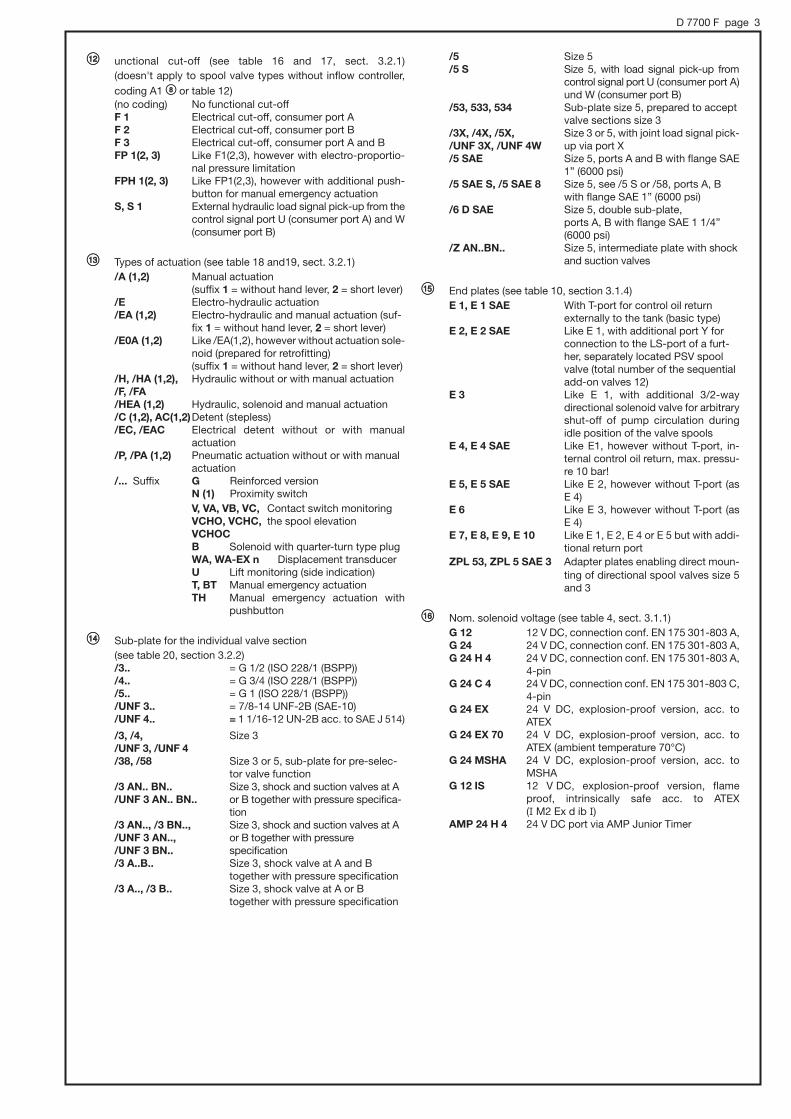
/5 Size 5 /5 S Size 5, with load signal pick-up from
control signal port U (consumer port A)und W (consumer port B)
/53, 533, 534 Sub-plate size 5, prepared to acceptvalve sections size 3
/3X, /4X, /5X, Size 3 or 5, with joint load signal pick-/UNF 3X, /UNF 4W up via port X/5 SAE Size 5, ports A and B with flange SAE
1” (6000 psi)/5 SAE S, /5 SAE 8 Size 5, see /5 S or /58, ports A, B
with flange SAE 1” (6000 psi)/6 D SAE Size 5, double sub-plate,
ports A, B with flange SAE 1 1/4”(6000 psi)
/Z AN..BN.. Size 5, intermediate plate with shockand suction valves
II End plates (see table 10, section 3.1.4) E 1, E 1 SAE With T-port for control oil return
externally to the tank (basic type)E 2, E 2 SAE Like E 1, with additional port Y for
connection to the LS-port of a furt-her, separately located PSV spoolvalve (total number of the sequentialadd-on valves 12)
E 3 Like E 1, with additional 3/2-way directional solenoid valve for arbitraryshut-off of pump circulation during idle position of the valve spools
E 4, E 4 SAE Like E1, however without T-port, in-ternal control oil return, max. pressu-re 10 bar!
E 5, E 5 SAE Like E 2, however without T-port (as E 4)
E 6 Like E 3, however without T-port (as E 4)
E 7, E 8, E 9, E 10 Like E 1, E 2, E 4 or E 5 but with addi-tional return port
ZPL 53, ZPL 5 SAE 3 Adapter plates enabling direct moun-ting of directional spool valves size 5and 3
JJ Nom. solenoid voltage (see table 4, sect. 3.1.1)G 12 12 V DC, connection conf. EN 175 301-803 A,G 24 24 V DC, connection conf. EN 175 301-803 A,G 24 H 4 24 V DC, connection conf. EN 175 301-803 A,
4-pinG 24 C 4 24 V DC, connection conf. EN 175 301-803 C,
4-pinG 24 EX 24 V DC, explosion-proof version, acc. to
ATEXG 24 EX 70 24 V DC, explosion-proof version, acc. to
ATEX (ambient temperature 70°C)G 24 MSHA 24 V DC, explosion-proof version, acc. to
MSHAG 12 IS 12 V DC, explosion-proof version, flame
proof, intrinsically safe acc. to ATEX (I M2 Ex d ib I)
AMP 24 H 4 24 V DC port via AMP Junior Timer

D 7700 F page 4
There are two basic variations of connection blocks:' Connection blocks with integrated 3-way flow controller, suitable for a fixed pump system (open-center) -type PSLF (see sect. 3.1.1)
' Connection blocks suited for a variable displacement pump system (closed center), a constant pressure systems, or if a second or more separately located directional spool valve banks are fed in parallel - type PSVF (see sect. 3.1.2).
Order coding for an inlet section as individual section (examples): PSLF A1 F/250 - 3 - G 24(Attention: Size specification absolutely necessary - 3 or -5) PSVF A2/300 - 5
3.1.1 Inlet sections for fixed pump systems (with integrated 3-way flow controller) type PSLF
Order examples: PSLF A 1F/300 /4 - 3 -...-E1 - G 24 (valve bank))
PSLF A H1F/300 - 3 - G 24 (individual section)
Table 10Table 1
Table 1: Basic type and size
Table 3: Coding of the sub-plate for the inlet sections
Type PSLF...-5 can be converted any time for use withvariable displacement pumps (similar to type PSVFAS..-5), see sect. 6.3.3.
Symbols
PSLF A(H)../..-3PSLF A(H)W../..-3
PSLF A(H)../..-5PSLF A(H)W../..-5
Coding andsize
PSLF A ..-3
PSLF A ..-5
Max. pump delivery flow (lpm)
approx. 100
approx. 350
Descrip-tion
Individualsection
Coding
/4
/UNF 4
/6
/7 SAE
Size
3
3
5
5
Ports ISO 228/1 (BSPP)or SAE 514 JP and R LS, M, T and Z
G 3/4 G 1/4
1 1/16-12 UN-2B 7/16-20 UNF-2B
G 1 1/4 G 1/4
SAE 1 1/2” G 1/4(6000 psi)
Basic type and additional elements (see table 1 and 2)
3. Available versions, main data3.1 Inlet section (control section)
Note: Sub-plates with SAE-flange must not be com-bined with sub-plates featuring tapped ports(e.g. /5 S)
Sub-plates (see table 3)
Table 2
Table 2: Coding for additional elements for notes and descripti-ons, see sect. 6.1 a)
Coding Description
no coding Standard Integrated combination of orifice, checkvalve, pre-load valve (pre-load pressureapprox. 25 bar).
W Like standard, but with increased throttle effect
G Restrictor check valve (without sequence valve), increased throttling effect
HCoding for 3-way flow controller with increased cir-culation pressure (see sect. 4.2). Intended for valvespools with increased flow (coding 5 acc. to table 15),pre-selector spool valve (coding 8 table 13).
TOnly available for type PSLF A..-3Provision for locking the 3-way flow controller to enable use with variable pump systems.
PSLF A../../4-3PSLF A../../UNF 4-3
PSLF A../../6-5PSLF A../../7 SAE-5
PSLF AG../..-3PSLF AG../..-5
Additional elementsThese additional elements areillustrated in flow patternsymbols of size 3, they do apply to size 5 in the same way.

D 7700 F page 5
Symbols
Table 5: Basic type and size
Type PSLF...-5 can be converted any time for use withvariable displacement pumps (similar to type PSVF AS..-5), see sect. 6.3.3.
Coding andsize
PSVF A ..-3
PSVF A ..-5
Max. pump delivery flow (lpm)
approx. 100
approx. 350
Descrip-tion
Individualsection
Basic type (see table 5) Sub-plates (see table 3)
Additional elements (see table 6) 1)
These additional elements are illustratedin flow pattern symbols of size 3, they doapply to size 5 in the same way.
3.1.2 Inlet sections for variable displacement pump systems / constant pressure system or for a second and all other separately parallel connected directional spool valve banks type PSVF
Order examples:
Nom. voltage see table 10
PSVF A 1F/300 /6 - 5 -...-E1 - G 24 (valve bank)
PSVF A B/250 - 3 (individual section)
Sub-plate see table 3, sect. 3.1.1
Table 4: Code letter for features within the LS-signal duct forthe damping of pump flow controllers (for notes andexplanation, see sect. 6.1 a) Additional features only suitable where variable displacement pumps are used (limitation of the controloil flow). Observe note at table 9!
Coding Description
no coding Standard, without additional element
S With integrated combination of orifice, check valve,pre-load valve (pre-load pressure approx. 25 bar)like standard element of type PSLF
W Like S, but with increased throttle effect
B With orifice # 0.8 mm within LS-duct (limiting thecontrol oil flow)
B 4, B 5, B 6, B 7
With orifice # 0.4 mm, 0.5 mm, 0.6 mm or 0.7 mmwithin LS-duct
PSVF A../..-3 PSVF A../..-5
PSVF A../4-3PSVF A../UNF 4-3
PSVF A../6-5PSVF A../7 SAE-5
PSVF AS...-3PSVF AS...-5
PSVF AB...-3PSVF AB...-5

D 7700 F page 6
3.1.3 Additional elements for the inlet sections
Order examples: PSLF A. 1F100 /380/4 - 3 -...- E1 - G24
PSVF A.1F /350 -5 - G24
Symbols
Coding Description
no coding
/...
Version without pressure limiting valve (only typePSVF)
With pressure limiting valve at PSLF and PSVF (pressure specification in bar)
Non piloted: PSL(V)F ...- 3Piloted: PSL(V)F ...- 5
Table 9: Tool adjustable pressure limiting valve for the main pressure.Adjustable from 50 up to 400 bar, after loosening thelock-nut (for symbol, see sect. 3.1.1 and 3.1.2).
These additional elements are illustrated in flow pattern symbols of size 3, they do apply to size 5 in the same way.
PSLF A 1(2)./...-3(5)PSVF A 1(2)./...-3(5)
PSL(V)F A..D
PSL(V)F..PA (PB,PD)
PSL(V)F A..F
PSL(V)F A..D..
PSL(V)F A..F..
Table 7: Coding for control oil supply (for symbol, see sect. 3.1.1and 3.1.2)
no coding Without pressure reducing valve for actuation cod-ing A, C or P acc. to sect. 3.2, table 18 or in the caseof external control oil supply (20-40 bar) for otheractuations
1
2
With integrated pressure reducing valve for internalcontrol oil supply for actuations coding H(HA, HEA,F, FA, FEA).. and E(EA).. or as pick-up for other con-trol valves (max. permissible control oil flow approx.2 lpm)Control pressure:Coding 1: approx. 20 bar (+ return pressure at R)Coding 2: approx. 40 bar (+ return pressure at R)
Coding
Table 8: Arbitrary idle pump circulation of all consumers by meansof 2/2-way solenoid valve type WN 1 conformingD 7470 A/1, 2/2-way solenoid valve type EM 21 DE(DSE)conforming D 7490/1 E or prop. pressure limiting valve
Note: To limit the control oil flow, when using the idle pump circulation with type PSV an additional element codingS, W or B 4, B 5, B 6 acc. to table 5 is required.
Attention: Observe note in sect. 6.1 a when using the valves for anemergency stop function!
Description
Coding Description
Coding Description
no coding If not required
F With WN 1F, idle pump circulation if valve is de-energized (emergency stop)
D With WN 1D, idle pump circulation if valve is ener-gized
F...
or
D...
With pressure limiting valve, which can be activat-ed as a second pressure stage (specify pressure inbar) (pre-set pressure, tool adjustable from 50 to400 bar). Example: PSLF A 1 F100/350-3..De-energized pmax = 100 barEnergized pmax = 350 bar
PA, PB,PD
Prop. pressure limiting valve enabling variable adjustment of the system pressure; Pressure range:PA 100...320 bar, PB 15...250 bar, PD 18...400 bar
Z With type EM 21 DSE, idle pump circulation if valve is de-energized (emergency stop)
ZM Like Z, but with lead sealed wing screw for emer-gency operation
V With type EM 21 DE, idle pump circulation if valveis energized
X... Additional LS pressure limitation (50...400 bar)Not suited to compensate pressure peaks on theconsumer side.
Table 8

D 7700 F page 7
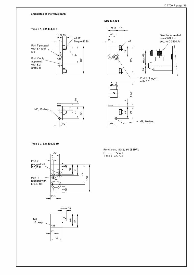
3.1.4 End plates of valve bank
Order example: PSLF A1 F100/380/6 - 5 -... - E 1 - G 24
End plate Description
Table 11: End plates
Externalport T (separatereturn pipeto the tank)
Internalcontrol oilreturngallery
Order coding of an end plate asseparate part(example): SLF 5 - E 1
SLF 3 - E 6 - G 24(State the size: SLF3- or -SLF5- !)
Note: ' The internal control oil return gallery is to be usedonly in systems where the return pressure is below 10 bar.
' End plates E.SAE in combination with sub-plates/..SAE (only size 5) or adapter plate ZPL 5 SAE 3 asconversion from sub-plates /.SAE size 5 to size 3
Symbols
E 1 E 2E 1 SAE E 2 SAE
E 3
E 4 E 5E 4 SAE E 5 SAE
E 1E 1 SAE
E 4E 4 SAE
E 2E 2 SAE
E 5E 5 SAE
With additional inlet port Y e.g. forconnecting the LS-control pipe of asubsequent PSVF spool valvebank.
E 3 E 6 Possibility for arbitrary shut-off of theidle pump circulation by means of a di-rectly mounted 3/2-way direct. seatedvalve WN1H acc. to D 7470A/1
E 7 E 9 Like E 1/E 4, but with additional return port R (only size 3)
E 8 E 10 Like E 2/E 5, but with additional return port R (only size 3)
Adapter plate to continue a prop. directional valve bank size 5 withsections of size 3. As separate part: SLF 5-ZPL 53
ZPL 53ZPL 5 SAE 3
Standard end plate
E 6
Table 10: Nominal voltage for solenoid actuation acc. to table 20 for all solenoid actuated functions of the valve bank, for details see sect.4.3 and 4.5
AMP 24 H 4
G 24 X 24
G 12 X 12
24 V DC
24 V DC
G 24 H 4 X 24 H 4 24 V DC
12 V DC
Note: ' Solenoids of explosion-proof design are only available for actuation E, EA or HE (A) (table 20). ' An intermediate plate ZPL 33/5 (see table 22) has to be provided between the valve sections when using solenoids
G 12 IS .. and G 24 MSHA ... . ' Coding G 24 C (X 24 C) is only available for solenoids of the electrical actuation (table 20) where there is no manual
emergency actuation. ' Coding AMP 24 not available for idle circulation valves coding D and F (table 8), intermediate plates ZPL 3 S (V) E (table 22),
end plates E 3, E 6 (table 11), intermediate plates /ZDS, /ZDR (table 19), functional cut-off, (table 17)
Standard, version with connection conf. EN 175 301-803 A with (G ..) or without (X ..) plug
Like G 24 (X 24), but solenoid for electrical actuation 4-pin, see sect. 4.3
G 24 C 4 X 24 C 4 24 V DC Version with connection conf. EN 175 301-803 C, 4-pin at solenoid actuation (table 20), with (G ..) or without (X ..) plug, see 4.3
Version with connection via AMP Junior Timer, 4-pin at electrical actuation (table 20), all othersolenoid actuated functions are 2-pin
G 24 EXG 24 EX-10 m
24 V DC For use in areas with explosion hazardous atmosphere. Suited for category 2 and 3, zone 1, 21, 2, 22. Protection class EEx m II 120° (T4), with cable length 3 m (no coding) or 10 m
Like G 24 EX .. , but for ambient temperature < 70°C
G 12 ISG 12 IS-10 m
G 24 EX 70G 24 EX 70-10 m
12 V DC
24 V DC
For use in mines and its on-surface systems, which can be endangered by firedamp and/orcombustible dust. Protection class I M2 Ex d ib I (flame proof, intrinsic safe), with cable length 5 m (no coding) or 10 m
G 24 MSHAG 24 MSHA-10 m
24 V DC For use in mines and its on-surface systems, where a MSHA (USA) or MA (China) approval ismandatory. Protection class I M2 Ex d I (flame proof, intrinsic safe), with cable length 5 m (no coding) or 10 m
Nominal voltageCoding Description

D 7700 F page 8
3.2 Valve sections3.2.1 Directional spool valve (individual valve)
Order examples: (valve bank) PSLF A1 F/320/4 - 3 - A2 L 63/40 F1 /EA /3 AN320 BN320 - E1 - G 24
(individual section) SLF 5 - A5 J 160/160 C250 /EA - G 24
Size
Table 13: Spool valve, basic version
Sect. 3.2.2
Note: Size specification is absolutely necessary!The valve spools are subsequently interchange-able, e.g. if a different flow rating than initiallyplanned becomes necessary (see sect. 6.3.4)
Table 20
Table 17
Table 16
Table 15
Table 14
Coding Description
A 2 Standard, with inflow controller, for simultaneous load compensated moving of several consumers(3/3-, 4/3-way spool valve, standard type)
A 1 Without inflow controller intended for singly / successively actuated functions. Additional functions on the consumer sideare not possible. For the max. consumer flow of the individual consumer, see table 15 and sect. 6.1 b)
A 5 With inflow controller (for symbol, see coding A2) but with reinforced spring at the 2-way flow controller (control pressureapprox. 9 bar). Only usable in conjunction with connection block type PSLF AH../...-3- or type PSVF with variable displace-ment pump / constant pressure system. Note see sect. 6.1 a and b.
A 7 With inflow controller (like coding 2) but enforced 2-way controller spring (control pressure approx. 13 bar). Only avail-able in combination with connection block type PSVF and variable displacement pump/constant pressure system, see note in sect. 6.1 b)
A 26A 56
Only size 3: With inflow controller coding 2 or 5, and additional rebound damping;Especially suited for oscillation inducing consumers (e.g. hydraulic motors with a lownumber of pistons)
A 8 4/3-way directional spool valve, Makes only sense with flow pattern symbol L and H and maximum flow. Only usable in conjunction with connection block type PSLF.H./... or type PSVF with variable displacement pump / constant pressuresystem.
AR 2, AR 5, AR 7
Like coding 2, 5, 7, but with additional check valve functionality (spool valve = slight leakage), see sect. 6.1 bOnly usable in conjunction with connection block type PSLF.H./... or type PSVF withvariable displacement pump / constant pressure system.
AX Blanking plate
Table 14: Symbols
L M F H J B R O G Valve spool with return throttling to assistoscillation dampening, see sect. 6.1 c
J, B, R, O, I, Y, Z, V
3/3-way spool valve, observe note in sect. 6.1 cG
4/2-way spool valve, observe note in sect. 6.1 cW
Valve spool with positive overlapping, see sect.6.1 c, only size 3
A, K, P, Q, T
Valve spool with wider fitting to prevent spoolsticking - intended for contamination prone systems
2/2-way directional spool valve for hydraulic motors, see sect. 6.1 e, only size 3
HW, OW
X

Valid for PSLF (integrated 3-way flow controller: |p ~ 10 bar),otherwise as guide line QA, B , Qnom · 0,2 ·|pcontrollerQrating - flow for code number A 2; |pcontroller stand-by pressure of the flow controller of the pump Example (size 3): Qrating = 25 lpm, |pcontroller = 14 bar;
QA;B , 42 lpm
D 7700 F page 9
Table 16: Secondary pressure limiting valves, only available withspool valves featuring an inflow controller, coding A 2and A 5 (acc. to table 12!). These are no shock valves!
Coding
no coding
A...
B...
A...B...
C...
Description
Without pressure limitation
Pressure limitation at A with pressure specification
Pressure limitation at B with pressure specification
Pressure limitation at A and B with pressure specifi-cation
Common pressure limitation for A and B with pres-sure specification
Pressure limitation pmin = 50 bar; pmax = 420 bar Example: SLF 3-A 2 H63/40 A250 B200/A
Table 17: Functional cut-off or prop. pressure limitation (only available with spool valves with inflow controller codingA 2, A 5 and A 7 acc. to table 15!)
Description
Without functional cut-off
Electric functional cut-off at A or B
Electric functional cut-off at A and B
Prop. pressure limitation for A or B resp. A and B, Version FPH. with additional emergencyactuation (no tools needed)
Only size 5: flange sided load signal portsU and W (G 1/8) for external piping, e.g. incombination with sub-plate /5 S, seesect. 3.2.2 table 20; Example: SLF 5-A 2 H 160/80 S/5 S
The signal ports are apparent as stan-dard (see flow pattern symbols on page10) in combination with coding A.., B..,A..B.. (see table 15 and 17) and F.1 (2,3),S1 (table 16 and 17)
Load signal ports U and W (G 1/8) for external piping; tapped ports at valve section
Coding
no coding
F 1, F 2
F 3
FP 1, FP 2, FP 3FPH 1, FPH 2, FPH 3
' There remains a residual pressure when the LS gallery is relieved. When the return line is depressurized the residual pressure will be: prelieved = |pblock + |pcontroller (|pcontroller= control pressure of the inflow controller acc. to table 13) Coding F., FP. : |pblock = 10 barCoding S, S 1, (X) : |pblock = 5 bar
' One joint LS-port X is standard on the flange side (see dimen-sional drawings, sect. 5)
' Size 5: combinations of coding F..1, FP.. or S 1 and solenoids G 24 MSHA or G 12 IS are not available!
' Coding F.., FP.. not available with solenoids G 24 Ex 70 and G 12 IS
Table 18: Combination possibilities for additional functions
Pressure limitation
no coding
A or BA and B
C
The signal ports are apparent as standard (see flow pattern symbols on page 10) in combination with coding A.., B.., A..B.. (seetable 15 and 17) and F.1 (2,3), S1 (table 16 and 17)
no coding
'
'
'
S 1
'
'
--
F 1, F 2, F 3, S 1FP 1, FP 2, FP 3FPH 1, FPH 2, FPH 3
'
'
--
Functional cut-off
S 1
S
Table 15: Max. flow P → A(B) acc. to the coding
Valve spool codingacc. to table 12
Note: The flow rate for the consumer ports A and B can be individually selected,e.g. 63/40, 40/80. This provides optimal adaptation to the respective consumer while exploiting the full functional spool lift. In additi-on there is the possibility of mechanical stroke limitation.
Coding and flow QA, B (lpm) at consumer port A and B
Coding Size
3
5
3
5
3
3
--
4
--
6
6
--
9
--
10
10
--
14
--
16
16
16
22
20
25
25
25
34
32
40
40
40
54
51
63
63
63
85
80
80
80
80
107
110
120
--
120
--
150
160
--
160
--
210
4
--
9
--
14
--
22
20
34
32
54
51
85
80
107
110
--
150
--
210
A 2
A 1,A 8
A 53
5
5
--
10
--
14
--
24
23
37
37
59
60
93
95
118
130
--
175
--
240A 7
3
5

D 7700 F page 10
Basic version (individual section acc. to table 12)
With respect to flow con-figuration and actuation,these symbols are neutraland must be supplement-ed by the correspondingflow pattern symbols il-lustrated in table 13 or 18and 19, see also examplein sect. 6.2
4/3-way directionalspool valve without
inflow controller A 1... (A 8...)
4/3-way direction-al spool valve withinflow controller
A 2... (A 5...)
Additional function:Secondary pressure limitation acc. to table 15 for spoolvalves with inflowcontroller (no shockvalve!)
..A... ..B... ..A...B... ..C...
Functional cut-off,acc. to table 16, forspool valves withinflow controller
Combination possibilities: ..S(only size 5)
..F(FP, FPH)1
A..F(FP, FPH)1B..F(FP, FPH)1A..B..F(FP, FPH)1
..F(FP, FPH)2
A..F(FP, FPH)2B..F(FP, FPH)2A..B..F(FP, FPH)2
..F(FP, FPH)3
A..F(FP, FPH)3B..F(FP, FPH)3A..B..F(FP, FPH)3
here type F 3here type FP 2here type F1
Example :SLF 5-A 2 J63/40
A 250 B 310 F 3/EA-G 24
1) 1) 1)
1) 1)1)1)
1) Ports U and W on the flange side only with size 5, see description in table 16, coding S

D 7700 F page 11
Table 20: Types of actuation (for further explanations, see sect. 4.3)
Nomenclature Manual actuation Electro-hydraulic actuation
Hydraulic actuation Pneumatic actuation
Manipulated variables
Note: ' Approximate values for start of flow at A or B (= min) up to max. consumer flow according to the flow coding table 15, see curves sect. 4.2.
' Difference between actuation H.. and F.. is the position of the control line ports. With actuations HE(A) or FE(A) observe also notes and circuit examples in sect. 6.1 i
' Type E0A prepared for retrofitting of a solenoid actuation' Type AC, EC, and EAC with detent in end position, stroke limitation not possible
Actuation angle min. approx. 5°max. approx. 30°
Control current ratioI/INmin. approx. 0.2max. approx. 1
Control pressure min. approx. 5 barmax. approx. 18 barmax. perm. 50
Control pressure min. approx. 2.5 barmax. approx. 7 bar
Spring return
Coding
Symbol
BG 3
BG 5
A C
AC
E
EC
EAE0AEAC
FF UNF
HH UNF
FAFA UNF
HAHA UNF
Detent electro-hydraulic
Combina-tion withmanual actuation
hydraulic Combinationwith manual actuation
Combinationwith solenoidand manualactuation
FEAFEA UNF
HEAHEA UNF
P PA

D 7700 F page 12
Table 20: Additional features for actuations
Type of actuation /coding
Suffix Description Example Symbols
A, EA, HA, PA, C 1 Manual actuation without hand lever EA 1, C 1
A, EA, HA, PA, C 2 Manual actuation with short hand lever. For dimensions see sect. 5.3. EA 2, A 2
A, EA, HA, C
VVAVBVC
VCHOVCHC
Mechanical micro switch (size 3 only), for monitoring the spool's idle position, (for data of the switch, see sect. 4.3V - Signal with start of movement, direction A or B (no side indication)VA - Signal with start of movement, direction AVB - Signal with start of movement, direction BVC - Signal with start of movement, direction A and B (separate
side indication)VCHO - Signal with start of movement, direction A and B separate
(2xNO-contactVCHC - Signal with start of movement, direction A and B separate
(2xNC-contact
EA VA,A 1 VB,C VC
A, EA, C N, N1 Proximity switch (size 3 only), for monitoring the spool's idle position (no side indication), for data, see sect. 4.3.Type N1- only mechanical setup: Proximity switch is customer furnis-hed (8x8x33mm central sensor area).
EA N,A 1 N 1
A, EA, C, PA, K WAWA-EX n
Integrated displacement transducer (Hall-sensor) with analogous signal output (lift monitoring)(WA-EX n, explosion-proof version conf. Ex nA II T4 X)
EA W,A 1 W,EA BW
A, EA, C, PA, K U Integrated spool monitoring for side indication (Triggered signal: ON / OFF) EA U
E, EA, HEA TTH
Additional manual emergency actuation for the solenoid at the integratedprop. Pressure reducing valve. Version TH with additional pushbutton for actuation without tool
ET, EA 1 T,EW TH
A, C, E, E0A G Reinforced version of the spring cover, suitable if high pressure surgesare expected in the gallery T.
ET 1 G, CG,A 1 G
E, EA,HEA B, BT Solenoid with quarter turn type plug (Bayonet PA 6, Co. Schlemmer D-85586 Poing, suited for taper with bayonet 10 SL), version BT with additional manual emergency actuation. Plug is not scope of delivery.
EB, EAB,EA 1 B
VA
VC
VB
1 2
WAU
T

D 7700 F page 13
3.2.2 Sub-plates
Order example: PSLF A1 F/320-3-A2 L 63/40 A300 F1/EA /3 AN320 BN320 - E1 - G 24
PSVF A2/300-5-A2 J 160/120/EA /Z AN300 BN280/5 - E4 - G 24
/3, /4 and /5, /53/5 SAE/UNF 3, /UNF 4
/38/58
/5 S, /5 SAE S
/3 AN..., /UNF 3 AN/3 BN.... (analog)
/3 A... B... /3 A.../3 B... (analog)
/Z AN..BN..
Table 21: Sub-plates
Symbols
/3 AN... BN.../UNF 3 AN... BN...
/3 X, /4 X, /5 X and /UNF 3 X
Note: Sub-plate with SAE-flange must not be combined with sub-plates (tapped ports) e.g.
/6 D SAE
/3 X, /UNF 3 X,/UNF 4 W
/4 X
/5 X
Coding Port size for A and B
/53, /533
/534
ISO 228/1 (BSPP)
G 1/2
G 3/4
G 1/2
G 3/4
G 1
SAE J 514
--
7/8-14 UNF-2B(1 1/16-12UNF-2B)
--
--
3
3
5
Size
5
Joint load signal pick-up port X for external circuitry
Description
/3, /UNF 3 G 1/2 7/8-14 UNF-2B 3 Standard
/38 G 1/2 -- 3 Sub-plate for pre-selector valve type SLF 3-A 8
/4, /UNF 4 G 3/4 7/8-14 UNF-2B 3 Standard
/5 G 1 -- 5 Standard
/3 AN... BN.../3 AN.../3 BN.../UNF 3 AN... BN.../UNF 3 AN.../UNF 3 BN...
G 1/2 7/8-14 UNF-2B 3 Shock and suction valves at A and B or A or B (state pressure in bar)
/3 A... B.../3 A.../3 B...
G 1 -- 3
/5 S G 1/2 -- 5
Shock valves at A and B or A or B (state pressure in bar)
Load signal pick-up ports U and W (G 1/4) for external circuitry
Sub-plate for valve section size 3 in a valve bank size 5 (saving an intermediate plate)
/58 G 1 -- 5 Sub-plate for pre-selector valve type SLF 5-A 8
/UNF 4 W
SAE 1” (6000 psi)/5 SAE, /5 SAE S,/5 SAE 8
5 Sub-plate with SAE-flange, analogue /5, /5 S and /58
SAE 1 1/4” (6000 psi)/6D SAE 5
5
Sub-plate with SAE-flange for combination of two valve sections, to achieve a load compensated consumer flow ofmax. 400 lpm
/Z AN..BN.. Intermediate plate with shock and suction valves --
1)
1) Gauge portsa and b onlywith coding/4, /4X and/5
1)
D 7700 F page 14
4. Characteristic data4.1 General and hydraulic
Type coding
Design
PSLF, PSVF and SLF
Directional spool valve for manifold mounting, up to 12 spool valves may be combined in a valvebank by means of sub-plates, all-steel design
Any
P = Pressure inlet (pump) R = ReturnA ,B = Consumer portsU, W, X = Load-signal outlet at the indiv. spool valve sectionLS = Load-signal outlet e.g. connection of pump metering valve at PSVF.
Attention: No pressure input! M = Pressure gauge connection (pump side)Z = Pilot pressure connection (20...40 bar inlet, 20 or 40 bar outlet)T = Control oil return portY = Load-signal inlet port (end plate E 2 and E 5)
Installation position
Ports
Size 3 Size 5
Indiv. section 4 x M8 4 x M10
Valve bank M8 M10
Mounting
Size 3 5
Inlet section PSLF, PSVF../.., PSVF..- 3.8 1) 3.3 1)
Valve section Actuation A, E, F, H, P 4.4 2) 6.6 2)EA, PA 4.8 2) 7.0 2)FA, HA 4.7 2) 6.6 2)FEA, HEA 5.1 2) 7.1 2)
Blanking plate AX 0.9 ---
Intermediate plate /Z AN..BN.. -- 3.1
Sub-plates /3, /38, /4, /5, /53, /533, /534, /5 S, /3 X, /5 X, /6 2.2 4.3/3 AN... BN..., /3 A..B.. 2.5 ---/5 SAE, /5 SAE S, /5 SAE 8 -- 9.2/6 D SAE -- 17.0
End plates E 1, E 2, E 4, E 5 0.8 1.8E 3 and E 6 2.1 3.1E 7, E 8, E 9, E 10 2.0 ---E 1 SAE ... E 5 SAE -- 2.9
Adapter plate ZPL 53, ZPL 5 SAE 3 5.0
See dimensional drawingsin sect. 5 ++
1) + 0.6 kg at version with solenoid valve WN1F(D), PA...PD acc. to table 8
2) + 0.4 kg at version with functional cut-off (coding F.., FP.., FPH..acc. to table 16)
P, R, A, B = Acc. to dimensional drawings (see sect. 5.10)M, LS, Z, T, Y = G 1/4 conform. ISO 228/1 (BSPP)U, W, X = Acc. to dimensional drawings (see sect. 5.9 and 5.10)
Indiv. valve section and sub-plates: All surfaces corrosion-inhibiting, gas nitrided(Solenoid at actuation E... and additional functions F1...F 3, FP 1...FP 3, FPH 1...FPH 3 inc galva-nized and olive-green anodized)
Port size
Surface coating
Mass (weight) approx. (kg)
Temperature Ambient: approx. -40 ... +80°C; Fluid: -25 ... +80°C, pay attention to the viscosity range!Start temperature down to -40°C are allowable (Pay attention to the viscosity range during start!),as long as the operation temperature during consequent running is at least 20K (Kelvin) higher.Biodegradable pressure fluids: Pay attention to manufacturer's information. With regard to the com-patibility with sealing materials do not exceed +70°C.Restriction for version with ex-proof solenoid:Ambient: -35 ... +40°C; Fluid: max. 70°C max. 70°C for version G 24 EX 70 Ambient: -35...+70°C,Fluid: max. 75°C
Rec. contamination class
Operating pressure
ISO 4406 18/14
pmax = 400 bar; Ports P, P1, A, B, LS, M, YThe max. pressure achievable at the consumer side of the spool valves is lowered by the amountequivalent to the internal control pressure drop at the 3-way flow regulator of the PSLF (see curves)or at the pump flow regulator (PSVF)..Return port R(R1) ≤ 50 bar; port T pressure less with separate pipe (e.g. 6x1) to the tank. It is recommended to employ end plate E 1, E 2, E 3, etc. with an additional leakage port, in case hig-her return pressure is anticipated. Port Z approx. 20 or 40 bar (acc. to coding, see table 7) (outlet);≤ 40 bar (inlet)
Control circuit
Flow
For control pressure, see Q-I-characteristics. The internal control oil circuit is sufficiently protect-ed against malfunctions caused by contamination by means of a disk filter.
Acc. to the specifications in table 14, in sect. 3.2.1
Pressure fluid Hydraulic fluid (DIN 51524 table 1 to 3); ISO VG 10 to 68 (DIN 51519)Viscosity range: min. 4; max. 1500 mm2/sec; Optimal operation range: 10...500 mm2/secAlso suitable are biodegradable pressure fluids of the type HEPG (Polyalkylenglycol) and HEES(synth. Ester) at operation temperatures up to +70°C. HETG (e.g. rape seed oil) or water based flu-ids e.g. HFA or HFC must not be used!

D 7700 F page 15
4.2 Curves
Main pressure limiting valve in the inlet section Inlet section PSLF A..Circulation pressure P→R
Prop. pressure limitationCoding PA ... PD acc. to table 8, sect. 3.1.3Coding FP(H) 1, FP(H) 2, FP(H) 3 acc. to table 16, sect. 3.2.1
2-way inflow controller
Directional spool valve section P→A(B), A(B)→R
Size 3 Size 5
Oil viscosity during measurement approx. 60 mm2/sec
Consumer flow curves (guide line, example is valve section with inflow controller type SLF. - A2 ../..)
Flow codingacc. to table 14
Flow codingacc. to table 14
Flow codingacc. to table 14
PSL(V)F A../..-3 PSL(V)F A../..-5P
ress
ure
sett
ing
(bar
)
Bac
k p
ress
ure|p
(bar
)
Load
pre
ssur
e (b
ar)
Pre
ssur
e se
ttin
g (b
ar)
Bac
k p
ress
ure|p
(bar
)
Flow Q (lpm)
Flow Q (lpm)
Flow Q (lpm) Flow Q (lpm)
Flow Q (lpm) Flow Q (lpm)
Control current I (A)
Con
sum
er fl
ow Q
A, B
(lpm
)
Control current I (A)←← 24 V DC
Control current I (A) ←← 12 V DC←← Control pressure (bar)
hydr. actuation H, F←← Angle at hand lever (°)
manual actuation A, C
A(B) →R (s
pool
valve
L,M
,F,H)
A(B) →R (spool
valve L,M,F,H)

D 7700 F page 16
Actuating moment (Nm) size 3 / 5Idle position End position
Version A approx. 2.3 / 3.0 approx. 3.4 / 7.5Version FA, FEA, HA, HEA, PA approx. 2.9 / 5.0 approx. 8.0 / 16.5Version EA, E0A approx. 2.4 / 3.0 approx. 6.0 / 12.0
4.3 ActuationsFor other data, such as codings, symbols etc., see table 18 sect. 3.2
Actuation A
Version with detent, fixation of the valve spools at any desired position (idle position with special notch)Version with detent, fixation of the valve spool at idle and both end positionsRequired pulse duration for switching: approx. 1 sec
Actuation C AC, EC, EAC
Prop.-Solenoid, manufactured and tested acc. to VDE 0580Twin solenoids are of wet armature design. The hydraulic fluid provides lubrication and protectionagainst corrosion.
Actuation E, EA, HE, HEA, FE, FEA
Specifications apply to all solenoid versions if not stated otherwise.Nom. voltage UN 24 V DC 12 V DCCoil resistance R20 26.6 Ω 6.3 Ω Current, cold I20 0.9 A 1.9 ALim. current IG (Ilim) 0.63 A 1.26 ACut-off energy WA ≤ 0.3 Ws ≤ 0.3 WsRel. duty cycle S 1 S 1(reference temp. 11 = 50°C)Protection class (assembled) 40...70Hz
(best 55 Hz)Dither amplitude AD
1) 20% ≤ AD ≤ 35%
Additional notes:See also Sk 7814, as wellas for additional compo-nents sect. 6.1 j!
Control current I/IN
Oil viscosity during mea-surement approx. 60 mm2/s
I - stroke- curve
Electrical connection Circuitryfor coding ..-G 12(24)
..-X 12(24)EN 175 301-803 AIP 65 (IEC 60529)(standard version)
Circuitryfor coding -AMP 24 H 4AMP Junior Timer,4-poligIP 65 (IEC 60529)
The IP-specification only applies when the plug is mounted as specified.
Circuitryfor coding EB, EABIP 67 (IEC 60529)
Circuitryfor coding ..-G 24 H 4, 4-poligIP 65 (IEC 60529)
Circuitryfor coding ..-G 24 C 4, 4-poligEN 175 301-803 CIP 65 (IEC 60529)
Coil a Coil b
Coil a Coil b
1) 100⋅= −
G
peakpeakD I
I(%)A

D 7700 F page 17
Certificate of conformity IBExU05ATEX 1116 XEx-proof level I M2 Ex d ib IDuty cycle S 1, one coil energized per solenoid housing Protection class IP 67 (IEC 60529) Nom. voltage UN 12 V DC II 1.7 ALim. current IG 0.4 A Coil resistance R20 22 ΩConditions of use: Max. ambient temperature +40°C Max. fluid temperature +70°C Surface coating Housing zinc galvanized
Coil and connection cavity are moldedElectrical design and testing conforming EN 60079-0 (general requests),
EN 50020 (intrinsic save “i”), EN 60079-1 (pressure resistant encapsulation “d”)
Electrical connection 4 x 0.5 mm2
Cable length 3 m or 10 m (cable ÖLFLEX-EB ® Co. Lapp, D-70565 Stuttgart) Coded leads: 1-4, insulation color: fair blue)
The complete circuit has to be designed and get approved acc. to EN 60079-25.
Actuation suffix E, EA, HE(A) Explosion-proof version of actuation(intrinsic save, flame proof )
Voltage specification G 12 IS
Protect against direct sun light !
Not in to combination with functional cut-offF(FP).. (table 17) or all other solenoids mounted onconnection blocks (table 3 a, 8), ancillary blocks(table 19), intermediate plates (table 22) and endplates (table 11)
Attention: Take polarity into account!
Certificate of conformity TÜV-A 02ATEX 0007 XEx-proof level II 2 GD T120°C IP67 EEx m II 120°C (T4) Duty cycle S 1, one coil energized per solenoid housing Protection class IP 67 (IEC 60529) Nom. voltage UN 24 V DC Coil resistance R20 26.6 ΩCurrent, cold I20 0.88 A Lim. current IG 0.63 A Max. residual ripple of the 15% supply voltageConditions of use: Max. ambient temperature +40°C Max. fluid temperature +70°C Fuse IF < 1.8 A each solenoid must be safe guarded
against overload and short-cut by fuse conformingIEC 60127 medium
Surface coating Housing zinc galvanizedCoil and connection cavity are molded
Electrical design and testing conforming EN 50014, VDE 0170/0171 T 1 and T 9 Electrical connection 4 x 0.5 mm2
Cable length 3 m or 10 m (cable ÖLFLEX-440P ® Co. Lapp, D-70565 Stuttgart)
For connection scheme. see “Actuation E, EA” (standard version)
Explosion-proof version of actuation E, EA Voltage specification G 24 EX
Attention :Additionally observe operating manuals B 01/2002 and B ATEX
Protect against direct sun light !
Not in to combination with functional cut-offF(FP).. (table 17) or all other solenoids mountedon connection blocks (table 3 a, 8), ancillaryblocks (table 19), intermediate plates (table 22)and end plates (table 11)
Certificate of conformity IBExU07ATEX 1089 XEx-proof level II 2G Ex d II B T4
II 2D Ex tD A21 T135°CDuty cycle S 1, one coil energized per solenoid housing Protection class IP 67 (IEC 60529) Nom. voltage UN 24 V DC Coil resistance R20 80 ΩLim. current IG 0.24 A Max. residual ripple of the 15% supply voltageConditions of use: Max. ambient temperature +70°C Max. fluid temperature +75°C Fuse IF < 0.5 A each solenoid must be safe guarded
against overload and short-cut by fuse conformingIEC 60127 medium
Surface coating Housing zinc galvanizedCoil and connection cavity are molded
Electrical design and testing conforming, EN 50014, VDE 0170/0171 T 1 and T 9 Electrical connection 4+1 x 0.5 mm2
Cable length 3 m or 10 m (cable ÖLFLEX-440P ® Co. Lapp, D-70565 Stuttgart)
Explosion-proof version of actuation E, EA, HE(A)Voltage specification G 24 EX 70
Attention:Additionally observe operating manuals B 01/2002 und B ATEX
Protect against direct sun light !
Not in to combination with functional cut-offF(FP).. (table 17) or all other solenoids mounted onconnection blocks (table 3 a, 8), ancillary blocks(table 19), intermediate plates (table 22) and endplates (table 11)
Note: Due to the utilized clamp diodes at the pulsed prop. amplifier PWM it is notpossible to measure the coil current during operation. Readings will usual-ly be too low and are additionally dependent on the supply voltage and thecoil resistance.
Coil 1 Coil 2
Coil 1 Coil 2
Coil 1 Coil 2

D 7700 F page 18
MSHA-approval (USA) 18-NXA 05 0003-0MA-approval (China) J2007101ATEX-Certificate of conformity IBExU05ATEX 1115 XEx-proof level I M2 Ex d I Duty cycle S 1, one coil energized per solenoid housing Protection class IP 67 (IEC 60529) Nom. voltage UN 12 V DC 24 V DCCoil resistance R20 6.3 Ω 26.6 ΩLim. current IG 1.33 A 0.63 ACurrent. cold I20 1.9 A 0.9 A Conditions of use: Max. ambient temperature +40°C Max. fluid temperature +70°C Fuse I = max. 3x IG, each solenoid must be safe guarded
against overload and short-cut by fuse conformingIEC 60127-2 UL 248
Surface coating Housing zinc galvanizedCoil and connection cavity are molded
Electrical design and testing conforming EN 60079-0 (general requests), EN 60079-1 pressure resistant encapsulation “d”)
Electrical connection 4 x 18 AWG (approx. 0.8 mm2)Cable length 3 m or 10 m Leads BK, WH, RD, GN; Item-Nr. 40003, General Cable
Actuation suffix E, EA, HE(A) (flame proof) Voltage specification G 24 MSHA
Attention:Additionally observe operating manuals B 05/2003 and B ATEX
The idle position of the valve spool is monitored by a contact switch from Co. Burgess ® type V 4 N 4 Sk 2 with lever AR 1Switch engaged at idle position Electr. connection via plug, e.g. type G 4 W 1 F ® Co. Hirschmann,
www.hirschmann.com, (not scope of delivery)Protection class IP 65 (IEC 60529)Circuit-breaking capacity up to 30 V DC = 5 AInductive load = 3 A
Actuation suffix VCHO, VCHC(only size 3)
The idle position of the valve spool is monitored by a contact switch from Co. Burgess ® type V 4 NS with lever AR 1Switch engaged at idle position Protection class IP 67 (IEC 60529) Circuit-breaking capacity up to = 5 A Inductive load = 3 A Cables 3 x 0.5 mm2 Litze PVC coated; length; 50 mm
black = inletblue = NO-contactgreen = NC-contact
The switch is highly protected by a sheet cover against exterior physical damage
Actuation suffix V, VA, VB, VC(only size 3)
VCHOCircuitry VCHC
Switch function S 1 - direction A S 2 - direction B
Control pressure approx. 5 bar (start of movement)approx. 18 bar (max. movement) max. perm. pressure 50 bar
The remote control pipes to the control ports 1 and 2 must be externally piped.Supply is via proportional pressure reducing valve e.g. type FB2/18 etc. orKFB2/18 (both acc. to D 6600)
Actuation suffix H, HA, HEA, F, FA, FEA
Control pressure approx. 2.5 bar(start of movement); approx. 7 bar (max. movement)
Actuation suffix P, PA
Coil a Coil b
D 7700 F page 19
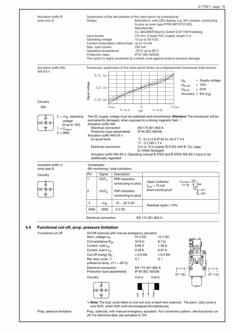
Supervision of the idle position of the valve spool via a transducerDesign 8x8x40mm, with LED-display, e.g. NC-contact, conducting
to plus an even type IFFM 08P/37O1/02LManufacturer: Co. BAUMER Electric GmbH D-61169 Friedberg
Input power #3 mm, 3 leads PVC coated, length 2 mOperating voltage 10 up to 30 V DC Current consumption without load up to 10 mAMax. load current 200 mAOperating temperature -25°C up to 80°C Protection class IP 67 (IEC 60529) The switch is highly protected by a sheet cover against exterior physical damage.
Actuation suffix N(only size 3)
Actuation suffix WA.WA-EX n
Sig
nal v
olta
ge
UB = Supply voltage UB max = 76% UB min = 24% Accuracy * 9% (UB)
2 = +UB operatingvoltage (5 up to 10V)
1 = Uoutput
3 = GND
WA
Actuation suffix U(only size 3)
Comparator(lift monitoring / side indication)
Electrical connection EN 175 301-803 A
Pin Signal Description
1 OUTA PNP-transistor conducting to plus)
2 OUTB PNP-transistor conducting to plus)
3 +UB 10 ... 32 V DC
GND GND 0 V DC
Open-Collector: Imax = 10 mA short-circuit proof
Residual ripple ≤ 10%
Circuitry
Circuitry
4.4 Functional cut-off, prop. pressure limitationOn/Off solenoid with manual emergency actuationNom. voltage UN 24 V DC 12 V DC Coil resistance R20 34.8 Ω 8.7 ΩCurrent, cold I20 0.69 A 1.38 A Current, warm I70 0.48 A 0.97 A Cut-off energy WA ≤ 0.3 Ws ≤ 0.3 Ws Rel. duty cycle 1) S 1 S 1 (reference temp. 11 = 50°C)
Electrical connection EN 175 301-803 AProtection type (assembled) IP 65 (IEC 60529)
Circuitry Coil a Coil b
1) Note: The duty cycle refers to one coil only of each twin solenoid. The perm. duty cycle isonly 50%, when both coils are energized simultaneously
Functional cut-off
Prop. pressure limitation Prop. solenoid, with manual emergency actuation. For connection pattern, see functional cut-off. For electrical data, see actuation E, EA.
The DC supply voltage must be stabilized and smoothened. Attention: The transducer will bepermanently damaged, when exposed to a strong magnetic field !Actuation suffix WA
Electrical connection EN 175 301-803 AProtection type (assembled) IP 65 (IEC 60529)
Actuation suffix WA-EX nEx-proof level Ex II 3 G IP 65 Ex nA II T 4 X
II 2 GD c T 4Electrical connection 3 m or 10 m (cable ÖLFLEX-440 ® Co. Lapp,
D-70565 Stuttgart)Actuation suffix WA-EX n: Operating manual B ATEX and B ATEX-WA-EX n have to be additionally regarded!
Lift
Transducer, supervision of the valve spool stroke via a displacement transducer (Hall-sensor)
D 7700 F page 20
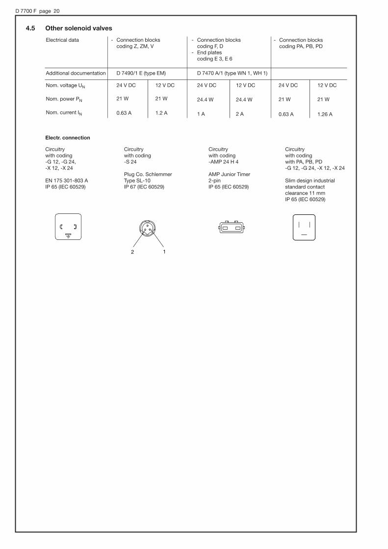
4.5 Other solenoid valves
Electrical data - Connection blocks coding Z, ZM, V
Electr. connection
Circuitry with codingwith PA, PB, PD -G 12, -G 24, -X 12, -X 24
Slim design industrialstandard contact clearance 11 mm IP 65 (IEC 60529)
- Connection blocks coding F, D
- End plates coding E 3, E 6
- Connection blocks coding PA, PB, PD
Nom. voltage UN
Nom. power PN
Nom. current IN
Additional documentation
24 V DC 12 V DC
21 W 21 W
0.63 A 1.2 A
D 7490/1 E (type EM)
24 V DC 12 V DC
24.4 W 24.4 W
1 A 2 A
D 7470 A/1 (type WN 1, WH 1)
24 V DC 12 V DC
21 W 21 W
0.63 A 1.26 A
Circuitrywith coding -G 12, -G 24,-X 12, -X 24
EN 175 301-803 AIP 65 (IEC 60529)
Circuitrywith coding -S 24
Plug Co. SchlemmerType SL-10IP 67 (IEC 60529)
Circuitrywith coding -AMP 24 H 4
AMP Junior Timer2-pinIP 65 (IEC 60529)
2 1

D 7700 F page 21
5. Dimensions All dimensions are in mm and are subject to change without notice!
M8, 10 deep
5.1 Size 35.1.1 Hole pattern of the sub-plate
5.1.2 Inlet section
M6, 8 deep
M8, 10 deep
Inlet section Valve section
70 (minimum distance)
Outline of the inletor valve section
Directional seatedvalve WN 1 F(D)acc. to D 7470 A/1
Pressure limiting valve(not valid fortype PSVF A..-3)
Valve sectionacc. to sect. 5.2
Socket head screw ISO 4762 M8x65-8.8-A2K Max. torque 23 Nm
Socket head screw ISO 4762 M6x75-8.8-A2KMax. torque 9 Nm
Type PSLF(V) A../..-3 and PSVF A..-3
Ports
A, B
LS, T, U, W, X, Z
L1
Ød
10.8
3.2
3.2
O-ring 1)PUR 90 Sh
12.37x2.62
4.47x1.78
7.65x1.78
Ports
P
F(R)
M, LS, L1, Z
Ød
12
14.5
3.2
O-ring 1)PUR 90 Sh
13.94x2.62
15.6x1.78
4.47x1.78
1) These O-rings are also available as complete seal kits, see also sect. 6.3.5Inlet section: DS 7700-F 32 Valve section: DS 7700-F 31
Inlet section: Valve section:
e , 12 at PSL> 15 at PSV
PSLF 3(4)PSLF 3(4) TPSLF 3(4) HPSLF 3(4) HT
d
22274045
app
rox.
75

D 7700 F page 22
Type PSL..F(D).../... PSV..F(D).../...
Type PSV...X...Type PSL..F(D)/... PSV..F(D)PSV..F(D)/...
Type PSL..Z(V).../... PSV..Z(V).../...
Type PSL..PA(PB, PD)/...PSV..PA(PB, PD)
Option ZM
approx. 56
app
rox.
78

D 7700 F page 23
5.1.3 Individual valve with manual actuation type A, C
1) Observe this operation area for the handlever with customer furnished manifolds!
Socket head screw ISO 4762 M8x90-8.8-A2K, max. torque 23 Nm
1 )
5.1.4 Individual valves with actuation type EA, E0A
Type EAE0A
Type E
Plug may be installedrotated by 4x90°,with cable gland
Tapped plugs with actuation typeE0A
(coding 2)
Lever housing at EA and HA(FA) can be angled at 180° inthe same manner as described at sect. 6.3.4
2) This dimension depends on the manufac-turer and can be up to 50 mm dependingon the max. permissible size according toEN 175 301-803 A
approx. 59 approx. 70
app
rox.
38.
52 )

D 7700 F page 24
Actuation type EB, EAB Actuation type EBT, EABT
Actuation type ET, EAT, ETH, EATH Actuation type E(EA)...-G(X) 24 C 4
Further versions
Actuation type E(EA)...-AMP H 4
Actuation type E(EA)...-G 24 EX Actuation type E(EA) -G 12 IS-G 24 MSHA
Actuation type E(EA)...-G 24 EX 70 1) Intermediate plate only in combinationwith actuation type EC and EAC
1)
approx. 37
approx. 37approx. 37

D 7700 F page 25
5.1.5 Individual valves with hydraulic actuation type FA, FEA, F
Type FEA, FEA 1(2)
1) This dimension depends on the manu-facturer and can be up to 50 mm depending on the max. permissible size according to EN 175 301-803 APlug may be installed rotated by 4x90°,with cable gland
Ports conf. ISO 228/1 (BSPP) or (SAE-4, SAE J 514):1 and 2 = G 1/8 or 7/16-20 UNF-2B
Type F
Type FA
approx. 69 approx. 70
approx. 58
app
rox.
38.
5 1 )

D 7700 F page 26
5.1.6 Individual valves with pneumatic actuation type PA and P 5.1.7 Blanking plate type AX
5.1.8 Lift monitoring
Type ... N(1)
Type a
WA 39
U 53
Cable gland
Type ... V (VA, VB, VC) Type WA-EX n
Mounting screw4 x socket head screwISO 4762-M8x25 - 8.8-A2K, 23 Nm
Ports conf. ISO 228/1 (BSPP):1 and 2 = G 1/8
Type ... WA, U
CableconnectorWA-EX n
Type h
... V (VA, VB) 20.5
... VC 27
approx. 122.5
approx. 100.5 approx. 70

D 7700 F page 27
5.1.9 Valve sections with secondary pressure limitation, functional cut-off and prop. pressure limitation
Type S 1 up to A..B..S 1
Type F 1 up to A..B.. F 3FP 1 up to A..B.. FP 3FPH 1 up to A..B.. FPH 3
Type A.. Type B..
Ports conf. ISO 228/1 (BSPP):W, U = G 1/8
Pushbutton(manual emergency actuation)with type FPH..
Type A..B..
Type C..
app
rox.
57
app
rox.
53
D 7700 F page 28
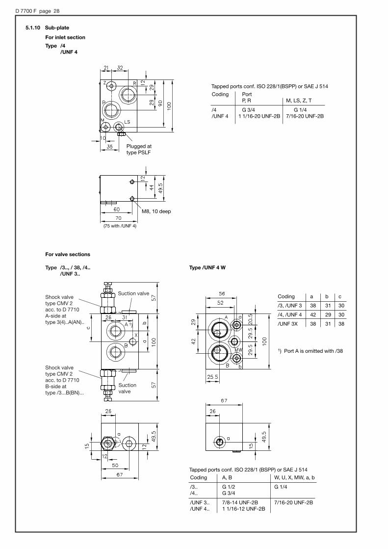
5.1.10 Sub-plate
For inlet section
Type /4 /UNF 4
Plugged attype PSLF
Tapped ports conf. ISO 228/1(BSPP) or SAE J 514
Coding
/4/UNF 4
M8, 10 deep
(75 with /UNF 4)
PortP, R M, LS, Z, T
G 3/4 G 1/41 1/16-20 UNF-2B 7/16-20 UNF-2B
For valve sections
Type /UNF 4 W
Coding
/3, /UNF 3
/4, /UNF 4
/UNF 3X
a
38
42
38
c
30
30
38
b
31
29
31
Coding A, B W, U, X, MW, a, b
/3.. G 1/2 G 1/4/4.. G 3/4
/UNF 3.. 7/8-14 UNF-2B 7/16-20 UNF-2B/UNF 4.. 1 1/16-12 UNF-2B
Tapped ports conf. ISO 228/1 (BSPP) or SAE J 514
1) Port A is omitted with /38
Shock valvetype CMV 2 acc. to D 7710A-side at type 3(4)..A(AN)..
Type /3.., / 38, /4.. /UNF 3..
Shock valvetype CMV 2 acc. to D 7710B-side at type /3...B(BN)...
Suctionvalve
Suction valve
1)
D 7700 F page 29
End plates of the valve bank
Type E 1, E 2, E 4, E 5
Type E 3, E 6
Type E 7, E 8, E 9, E 10
Port T pluggedwith E 6
Ports conf. ISO 228/1 (BSPP):R = G 3/4T and Y = G 1/4
Directional seatedvalve WN 1 H acc. to D 7470 A/1
M8, 10 deep
M8, 10 deep
a/f
M8, 10 deep
a/f 17Torque 46 Nm
Port Y onlyapparentwith E 2and E 5!
Port T pluggedwith E 4 and E 5 !
Port Yplugged withE 7, E 9!
Port Tplugged withE 9, E 10!
approx. 15
O-ring 1)PUR 90 Sh
17.12x2.62
4.47x1.78
7.65x1.78
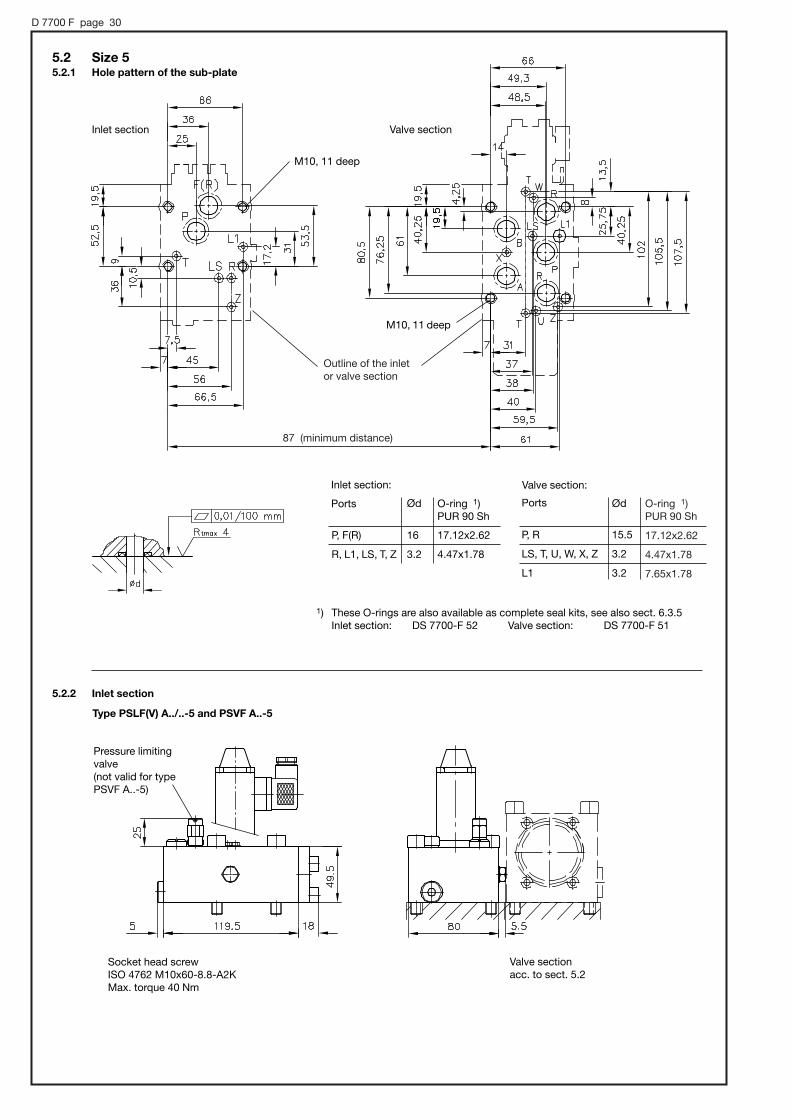
D 7700 F page 30
M10, 11 deep
Ports
P, R
LS, T, U, W, X, Z
L1
Ød
15.5
3.2
3.2
M10, 11 deep
1) These O-rings are also available as complete seal kits, see also sect. 6.3.5Inlet section: DS 7700-F 52 Valve section: DS 7700-F 51
5.2 Size 55.2.1 Hole pattern of the sub-plate
Inlet section Valve section
Valve section:
87 (minimum distance)
Outline of the inletor valve section
5.2.2 Inlet section
Type PSLF(V) A../..-5 and PSVF A..-5
Pressure limitingvalve(not valid for typePSVF A..-5)
Ports Ød O-ring 1)PUR 90 Sh
P, F(R)
R, L1, LS, T, Z
16
3.2
17.12x2.62
4.47x1.78
Inlet section:
Valve sectionacc. to sect. 5.2
Socket head screw ISO 4762 M10x60-8.8-A2K Max. torque 40 Nm

D 7700 F page 31
Type PSL..F(D).../... PSV..F(D).../...
Type PSV...X...Type PSL..F(D)/... PSV..F(D)PSV..F(D)/...
Type PSL..Z(V).../... PSV..Z(V).../...
Type PSL..PA(PB, PD)/...PSV..PA(PB, PD)
Option ZM
approx. 56
app
rox.
78
D 7700 F page 32
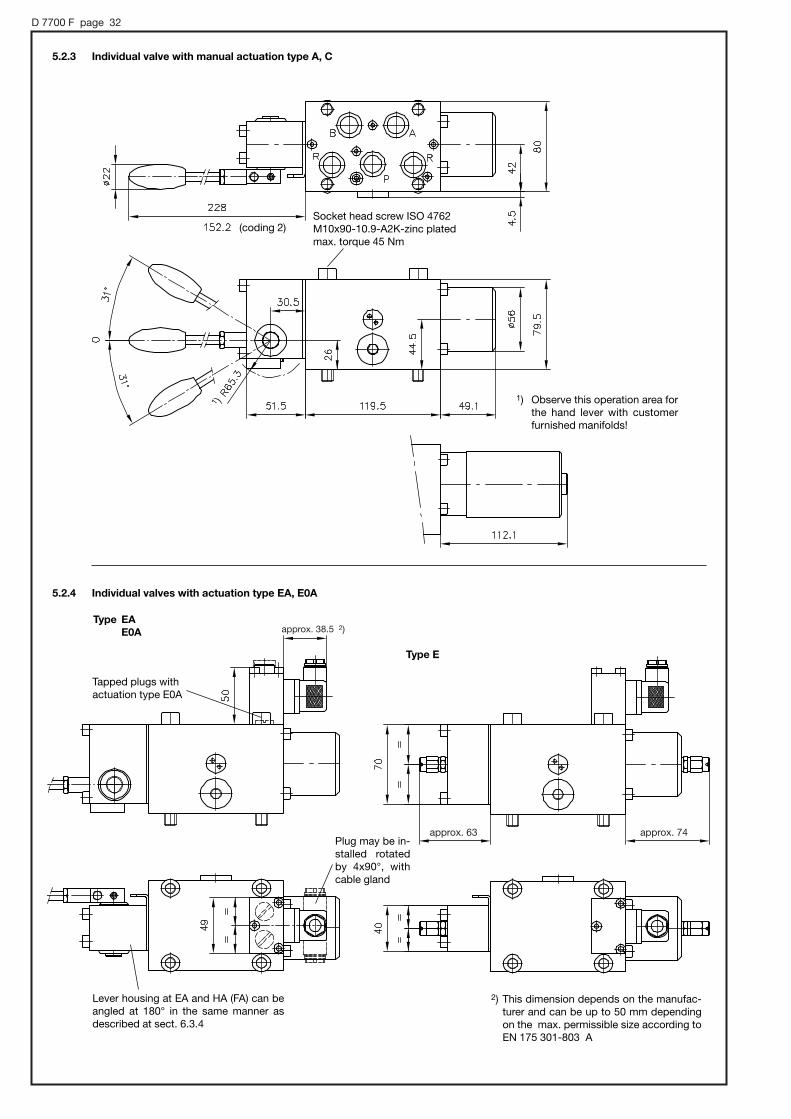
5.2.3 Individual valve with manual actuation type A, C
1) Observe this operation area forthe hand lever with customerfurnished manifolds!
Socket head screw ISO 4762 M10x90-10.9-A2K-zinc platedmax. torque 45 Nm
(coding 2)
1 )
5.2.4 Individual valves with actuation type EA, E0A
Type EAE0A
Plug may be in-stalled rotatedby 4x90°, withcable gland
Type E
Tapped plugs with actuation type E0A
Lever housing at EA and HA (FA) can beangled at 180° in the same manner as described at sect. 6.3.4
2) This dimension depends on the manufac-turer and can be up to 50 mm dependingon the max. permissible size according toEN 175 301-803 A
approx. 38.5 2)
approx. 63 approx. 74

D 7700 F page 33
Actuation type EB, EAB Actuation type EBT, EABT
Actuation type ET, EAT, ETH, EATH Actuation type E(EA)...-G(X) 24 C 4
Additional versions
Actuation type E(EA)...-AMP H 4
Actuation type E(EA)...-G 24 EX Actuation type E(EA) - G 12 IS- G 24 MSHA
Actuation type EB, EAB E(EA)...-G 24 EX 70
app
rox.
37
app
rox.
34
app
rox.
37
D 7700 F page 34
5.2.6 Individual valves with pneumatic actuation type PA and P
Type HA, FA Type HEA, FEA
Ports conf. ISO 228/1 (BSPP) or (SAE-4, SAE J 514):1 and 2 = G 1/4 or 7/16-20 UNF-2B
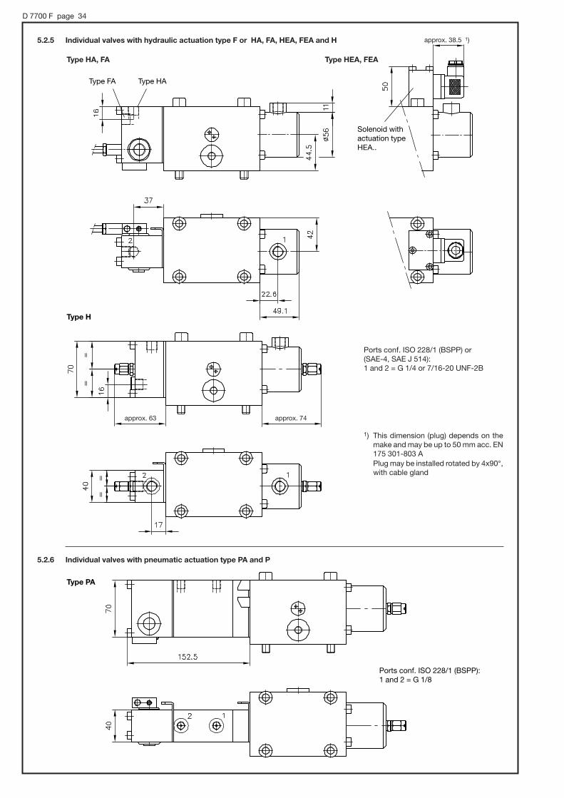
5.2.5 Individual valves with hydraulic actuation type F or HA, FA, HEA, FEA and H
1) This dimension (plug) depends on themake and may be up to 50 mm acc. EN175 301-803 A Plug may be installed rotated by 4x90°,with cable gland
Type HAType FA
Solenoid withactuation typeHEA..
Type H
Ports conf. ISO 228/1 (BSPP):1 and 2 = G 1/8
Type PA
approx. 63 approx. 74
approx. 38.5 1)

D 7700 F page 35
5.2.7 Blanking plate type AX
Mounting screw4 x socket headscrew ISO 4762M10x35 - 8.8-A2K,40 Nm
5.2.9 Valve sections with secondary pressure limitation, functional cut-off and prop. pressure limitation
Type A..B..
Type C..
5.2.8 Lift monitoring
Type WA, WA-EX n
Cable with codingWA-EX n
Type P
Type A.. Type B..
approx. 74approx. 120

D 7700 F page 36
Type S 1 up to A..B..S 1
Type F 1 up to A..B.. F 3FP 1 up to A..B.. FP 3FPH 1 up to A..B.. FPH 3
Ports conf. ISO 228/1 (BSPP):W, U = G 1/8
Pushbutton(manual emergency actuation)with type FPH..
5.2.10 Sub-plate Type /Z AN... BN...
app
rox.
239
app
rox.
57
app
rox.
53
D 7700 F page 37
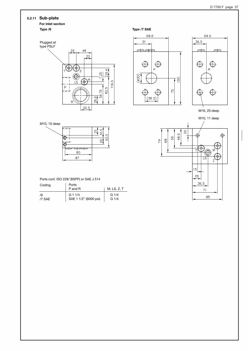
5.2.11 Sub-plateFor inlet section
Type /6 Type /7 SAE
M10, 11 deep
M16, 20 deep
Plugged attype PSLF
M10, 10 deep
Ports conf. ISO 228/ BSPP) or SAE J 514
Coding
/6/7 SAE
PortsP and R M, LS, Z, T
G 1 1/4 G 1/4SAE 1 1/2” (6000 psi) G 1/4
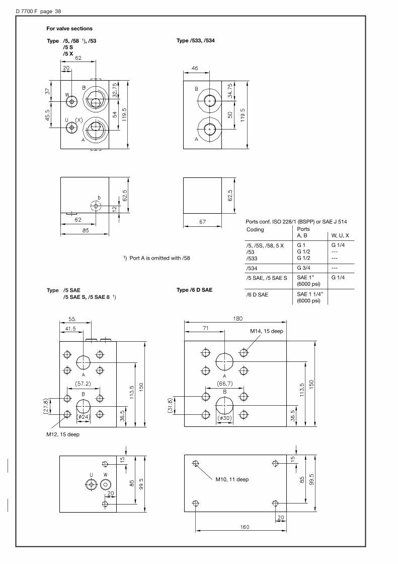
D 7700 F page 38
Type /5 SAE/5 SAE S, /5 SAE 8 1)
M12, 15 deep
Type /5, /58 1), /53 /5 S/5 X
Type /533, /534
1) Port A is omitted with /58
For valve sections
Type /6 D SAE
M14, 15 deep
M10, 11 deep
Ports conf. ISO 228/1 (BSPP) or SAE J 514PortsA, B W, U, X
G 1 G 1/4G 1/2 ---G 1/2 ---
Coding
/5, /5S, /58, 5 X/53/533
G 3/4 ---
SAE 1” G 1/4(6000 psi)
/534
/5 SAE, /5 SAE S
SAE 1 1/4”(6000 psi)
/6 D SAE
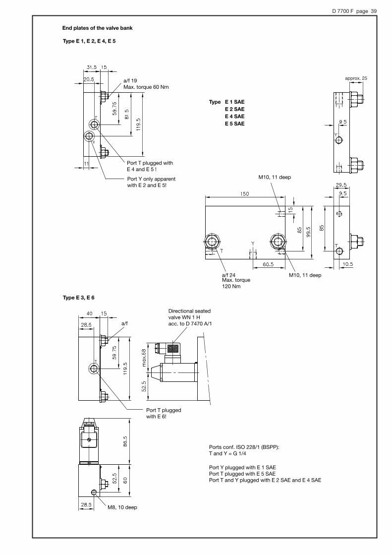
D 7700 F page 39
Type E 1 SAEE 2 SAEE 4 SAEE 5 SAE
M10, 11 deep
M10, 11 deepa/f 24Max. torque120 Nm
End plates of the valve bank
Type E 1, E 2, E 4, E 5
Type E 3, E 6
Port T pluggedwith E 6!
Directional seatedvalve WN 1 H acc. to D 7470 A/1
M8, 10 deep
a/f
a/f 19 Max. torque 60 Nm
Port T plugged withE 4 and E 5 !
Port Y only apparentwith E 2 and E 5!
Ports conf. ISO 228/1 (BSPP):T and Y = G 1/4
Port Y plugged with E 1 SAE Port T plugged with E 5 SAE Port T and Y plugged with E 2 SAE and E 4 SAE
approx. 25
D 7700 F page 40
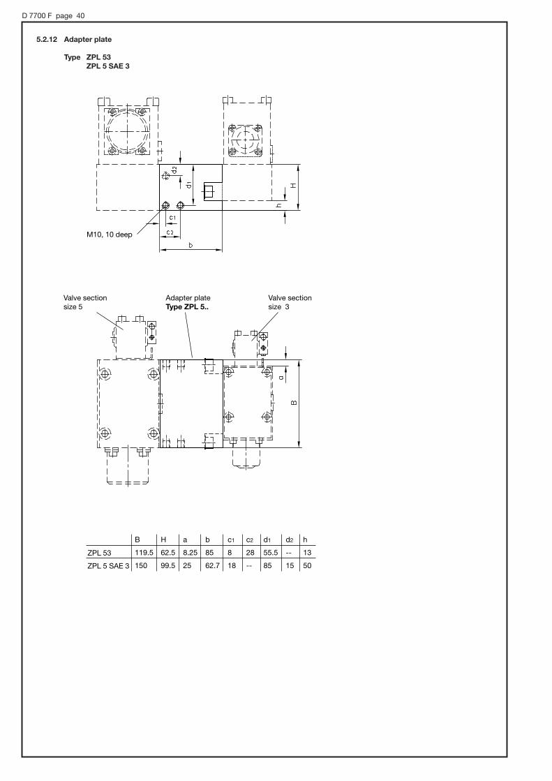
5.2.12 Adapter plate
Type ZPL 53ZPL 5 SAE 3
ZPL 53
ZPL 5 SAE 3
B
119.5
150
H
62.5
99.5
a
8.25
25
b
85
62.7
c1
8
18
c2
28
--
d1
55.5
85
d2
--
15
h
13
50
M10, 10 deep
Valve sectionsize 5
Adapter plateType ZPL 5..
Valve sectionsize 3
D 7700 F page 41
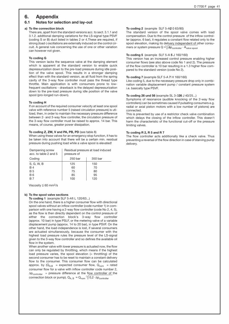
a) To the connection blockThere are, apart from the standard versions acc. to sect. 3.1.1 and3.1.2. additional damping variations for the LS-signal type PSVF(coding S or B) duct listed in tables 2 or 4.These are required, ifstrong (load-) oscillations are externally induced on the control cir-cuit. A general rule concerning the use of one or other variationcan however not given.
To coding GThis version lacks the sequence valve at the damping elementwhich is apparent at the standard version to enable quick depressurization down to the pre-load pressure during idle posi-tion of the valve spool. This results in a stronger damping effect than with the standard version, as all fluid from the springcavity of the 3-way flow controller must pass the thread typethrottle. Main application is with consumers prone to low-frequent oscillations - drawback is the delayed depressurizationdown to the pre-load pressure during idle position of the valvespool (pro-longed run-down).
To coding H If on account of the required consumer velocity at least one spoolvalve with reference number 5 (raised circulation pressure) is uti-lized, then, in order to maintain the necessary pressure differencebetween 2- and 3-way flow controller, the circulation pressure ofthe 3-way flow controller must be raised to approx. 14 bar. Thismeans, of course, greater power dissipation.
To coding Z, ZM, V and PA, PB, PD (see table 8) When using these valves for an emergency stop function, it has tobe taken into account that there will be a certain min. residualpressure during pushing load while a valve spool is elevated!
Viscosity $ 60 mm2/s
b) To the spool valve sectionsTo coding 1 (example SLF 5-A1 L 120/63...) On the one hand, there is a higher consumer flow with directionalspool valves without an inflow controller (code number 1) in com-parison with one having a 2-way flow controller (code No 2, 4, 5),as the flow is then directly dependent on the control pressure ofeither the connection block's 3-way flow controller (approx. 10 bar) in type PSLF, or the metering valve of a variabledisplacement pump (approx. 14 to 20 bar), in type PSVF. On theother hand, the load-independence is lost, if several consumersare actuated simultaneously, because the consumer with the highest load pressure rules the pressure level of the LS-signal given to the 3-way flow controller and so defines the available oilflow in the system. When another valve with lower pressure is actuated now, the flowcan only be regulated by throttling, which means if the highest load pressure varies, the spool elevation (= throttling) of the second consumer has to be reset to maintain a constant deliveryflow to the consumer. This consumer flow can be calculated approx. by (QA;B = expected consumer flow, Qnom = rated consumer flow for a valve with inflow controller code number 2,|pcontroller = pressure difference at the flow controller of theconnection block or pump). QA, B , Qnom · 0,2 ·|pcontroller
To coding 2 (example SLF 5-A2 0 63/80)The standard version of the spool valve comes with load compensation. Due to the control pressure of the inflow control-ler (approx. 6 bar), it regulates a constant flow related only to thespool elevation, making its delivery independent of other consu-mers or system pressure Q , ||pcontroller · Avalve spool
To coding 5 (example SLF 5-A 5 J 160/160)This version has an increased control pressure enabling higherconsumer flows (see also above code No 1 and 2). The pressureof the flow controller is 10 bar resulting in a 1.3 higher flow com-pared to the standard version (code No 2).
To coding 7 (example SLF 5-A 7 H 160/160) Like coding 5, due to the necessary pressure drop only in combi-nation variable displacement pump / constant pressure systemi.e. basically type PSVF.
To coding 26 und 56 (example SL 3-326 J 40/25...) Symptoms of resonance (audible knocking of the 2-way flow controllers) can be sometimes caused if pulsating consumers e.g.radial or axial piston motors with a low number of pistons) areconnected.This is prevented by use of a restrictor check valve combinationwhich delays the closing of the inflow controller. This doesn'tharm the characteristic of the functional cut-off or the pressure limiting valves.
To coding R 2, R 5 and R 7The flow controller acts additionally like a check valve. Thus preventing a reversal of the flow direction in case of starving pumpdelivery.
6. Appendix 6.1 Notes for selection and lay-out
Dampening screwacc. to table 2 and 5
Coding
Residual pressure at load inducedpressure of
250 bar 350 bar
S, G, W, BB 4B 5B 6B 7
125 15060 7075 8085 95
100 120

D 7700 F page 42
Cylinder area ratioApiston /Arod
= 1
. 1
Valve spool code letter
Piston side
P...
connection A A, T
connection B Q, K
Example
P 40/40
T 25/16
Q 40/63
Symbols Description Application
J, B, R, O Creation of a backpressure of approx. 20bar at 1/3 spool lift andmore.
Creation of a back pres-sure of approx. 100 barfor up to 1/3 spool lift
I, Y, Z, V
When combined withover-center valves e.g.for boom controls
Hydraulic motors (be-cause of pressure risedue to area ratio 1:1),e.g. with cabin slewing
SymbolsI, Y, Z, V
SymbolsJ, B, R, O
SymbolsL, M, F, HB
ack
pre
ssur
e |p
A(B
)-R
WX
Coding acc.to table 13
2(1)5
Qmax A, B (lpm)
50 120(67) (150)67 150
Coding acc.to table 13
2(1)5
Qmax A, B
(lpm)
80(107)107
Available versions:
SL 3-W 50/50SL 5-W 120/120
SL 3-X 80
KQTAP
c) Flow-pattern variationsFlow pattern symbol J, B, R, O and I, Y, Z, VOscillations may occur depending on application during start (e.g.winches) or during normal operation (e.g. crane booms). They canbe caused by the natural frequency of the hydraulic motors or external load variations e.g. swinging load. The flow coding (table 15) of the respective spool should correspond to the cylin-der ratio as far as possible.
Flow pattern symbol W This 4/2-way directional spool valve is intended for applicationswhere a constant velocity is required e.g. blower or generator drives. The ability of prop. speed control is restricted, but load independency is ensured via the inflow controller (table 13).
Flow pattern symbol X This 2/2-way directional spool valve is intended for hydraulic
I Y Z V
Available versions:
SL 3 - I 6/6I 10/10I 16/16I 25/25I 30/30I 40/40I 63/63I 80/80
SL 3 - V 6/6V 10/10V 16/16V 25/25V 40/40V 63/63V 80/80
SL 3 - Y 45/45Y 60/60
SL 3 - Z 25/25Z 45/45Z 60/60
SL 5 - I 25/25I 120/120I 140/140I 160/160
SL 5 - Y 150/150
SL 5 - Z 80/80
SL 5 - V 25/25V 120/120V 140/140
motors (e.g. fan drives) and features maximum speed in idle position. The speed can be reduced proportionally down to dead-halt by energizing the side "b". The load-independence isprovided when combined with an inflow controller (table 13).
Symbols
Flow pattern symbol P, A, T, Q, K (only size 3)
These spools show positive overlap. Type P overlaps in both swit-ching directions, i.e. during elevation of the spool the connectionP → A(B) is opened before of connection B(A) → R. This results in an undesired pressure intensification at cylinders(area ration . 1), therefore we recommend type A, T, Q or K asthese have a one-sided overlapping only. They are intended forconsumers such as hydro-motors / double acting cylinders (arearatio 1:1) with righting moments / -forces, as well as at cylinders with drawing loads (area ratio . 1). A short-term preloading prevents "lowering jolts" and "running empty". These valve spoolscan substitute load-holding valves to a limited extent. It should betaken into account, that a short-term working against the max. system pressure takes place.The flow coding for A should be selected higher than for B withspool codings A and T to prevent unintended pressure intensifi-cations (for spool codings Q and K Qnom A < Qnom B )
Symbols

D 7700 F page 43
Flow pattern symbol G 3/3-way directional spool valve for single acting cylinders Restrictions:' there is no load signal triggered via the LS-line' Therefore only usable at open center systems (type PSLF)
and electric actuation with restrictions – idle pump circulationpressure approx. 11 bar
' The flow while lowering is only throttled (no flow control func-tionality) and therefore load-dependent. It is therefore neces-sary (safety!) to limit the drop rate by a drop rate braking valvee.g. type SB acc. to D 6920
Available version:SL 3 - G 80/40SL 5 - G 160/160
d) Variations for special operation conditions or -requirementsOperation at potentially explosive areaselectro-hydraulic actuation (type E or EA) version G 24 EX..., seesect. 3.1.4 table 10 and sect. 4.3
Monitoring of the spool elevation (safety- / switching function)with contact- or proximity switch for monitoring the idle positionof the valve spool (suffix to the types A, C, EA, HA, HEA, PA acc.to sect. 3.2.1 tables 20 and 21 and sect. 4.3)
Maritime ambient climateThe aggressive sea atmosphere requires sufficient corrosion protection of all moving part of the actuations with hand lever. Theactuation shaft in the hand lever housing is therefore made ofstainless steel as standard. All other parts are either corrosion inhibiting gas nitrided or made of stainless steel. Exception: Housing of pneumatic actuation P or PA which is made of anodized light alloy.
Pressure surges in the return line Minor leakage may appear at the spring domes of actuations type AS, CS, E, EAS and E0AS when excessive pressure peaks (>150 bar) do occur in the return line. This can be prevented by use of enforcement flanges (suffix G acc. to table 21 in sect.3.2.1) (suffix G acc. to table 21 in sect. 3.2.1)
Note: The perm. pressure in the return line is limited to approx. 50 bar (see sect. 4.1). The functionality of the actuation solenoids could be harmed in case of excessive pressure.
e) Use of variable displacement pumpsWith Load-sensing controls in alliance with variable displacementpumps, the LS-signal duct for the pump pressure-flow controller(Load-Sensing metering valve) is relieved, to minimize circulationlosses during idle position (no consumer flow ). This limiting takesplace via the proportional spool valves. Without this decompres-sion the pump would have to work during no-lift position with allthe remaining flow against the pressure set at the safety valve ofthe pressure regulator.As there exist spool valves without this limiting possibility, some brands of pressure-flow controllers have a internal bypass orifice or throttle between LS-signal entrance and decompressed leakage outlet.In case of the prop. spool valves type PSVF this is not necessaryand can even cause malfunctions due to lost control oil. The con-trol oil flow is for functional reasons consciously limited (approx. 2 lpm) (slow-motion of the consumer). Note: Care must therefore be taken, to ensure that a possible bypass orifice in the pressure-flow regulator is plugged!
f) Combination with load-holding valvesIt can happen due to exterior variations of load and resonance thatthe control system starts to oscillate, if three regulation devices,the 3-way flow controller in the pump or the connection block, the2-way flow controller at the spool valve section plus load holdinginsert are connected in series. This can be effectively suppressedby systematic use of a bypass orifice and throttle-, check-, pre-load valve combination within the control oil circuit at the load-holding valve type LHDV acc. to D 7770. A similar behaviorcan be achieved with use of the over-center valves type LHT acc.to D 7918.
g) Combination of more than 12 spool valvesThrough the consecutive connection of the LS-signal duct, a total of max. 12 spool valves can be linked. Whether the spool valves are arranged in one or more valve banks is irrelevant. Thisrestriction results from the only limited available oil flow (ensuringslow-motion movements). If more than 12 spool valves in separa-ted directional spool valve banks are to be coupled via the LS-signal, a chaining via external shuttle valves is to be used.
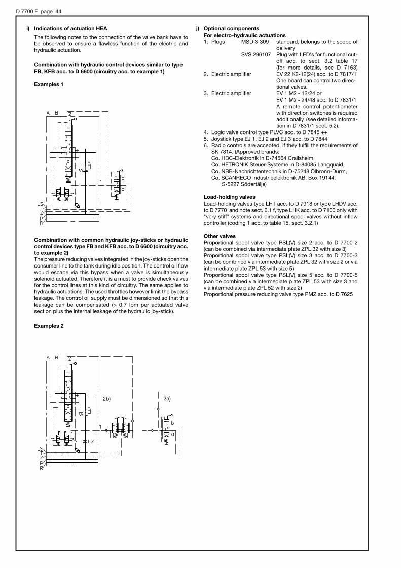
D 7700 F page 44
2b) 2a)
i) Indications of actuation HEA
The following notes to the connection of the valve bank have tobe observed to ensure a flawless function of the electric and hydraulic actuation.
Combination with hydraulic control devices similar to typeFB, KFB acc. to D 6600 (circuitry acc. to example 1)
Examples 1
Combination with common hydraulic joy-sticks or hydrauliccontrol devices type FB and KFB acc. to D 6600 (circuitry acc.to example 2) The pressure reducing valves integrated in the joy-sticks open theconsumer line to the tank during idle position. The control oil flowwould escape via this bypass when a valve is simultaneously solenoid actuated. Therefore it is a must to provide check valvesfor the control lines at this kind of circuitry. The same applies tohydraulic actuations. The used throttles however limit the bypassleakage. The control oil supply must be dimensioned so that thisleakage can be compensated (> 0.7 lpm per actuated valve section plus the internal leakage of the hydraulic joy-stick).
Examples 2
j) Optional components For electro-hydraulic actuations1. Plugs MSD 3-309 standard, belongs to the scope of
deliverySVS 296107 Plug with LED's for functional cut-
off acc. to sect. 3.2 table 17(for more details, see D 7163)
2. Electric amplifier EV 22 K2-12(24) acc. to D 7817/1 One board can control two direc-tional valves.
3. Electric amplifier EV 1 M2 - 12/24 or EV 1 M2 - 24/48 acc. to D 7831/1 A remote control potentiometerwith direction switches is requiredadditionally (see detailed informa-tion in D 7831/1 sect. 5.2).
4. Logic valve control type PLVC acc. to D 7845 ++5. Joystick type EJ 1, EJ 2 and EJ 3 acc. to D 78446. Radio controls are accepted, if they fulfill the requirements of
SK 7814. (Approved brands: Co. HBC-Elektronik in D-74564 Crailsheim, Co. HETRONIK Steuer-Systeme in D-84085 Langquaid, Co. NBB-Nachrichtentechnik in D-75248 Ölbronn-Dürrn, Co. SCANRECO Industrieelektronik AB, Box 19144,
S-5227 Södertälje)
Load-holding valves Load-holding valves type LHT acc. to D 7918 or type LHDV acc.to D 7770 and note sect. 6.1 f, type LHK acc. to D 7100 only with"very stiff" systems and directional spool valves without inflowcontroller (coding 1 acc. to table 15, sect. 3.2.1)
Other valvesProportional spool valve type PSL(V) size 2 acc. to D 7700-2 (can be combined via intermediate plate ZPL 32 with size 3)Proportional spool valve type PSL(V) size 3 acc. to D 7700-3 (can be combined via intermediate plate ZPL 32 with size 2 or viaintermediate plate ZPL 53 with size 5)Proportional spool valve type PSL(V) size 5 acc. to D 7700-5 (can be combined via intermediate plate ZPL 53 with size 3 andvia intermediate plate ZPL 52 with size 2)Proportional pressure reducing valve type PMZ acc. to D 7625

D 7700 F page 45
6.2 Example circuit
Control system with PSVF, and variable displacement pump
PSVF A1/380/4 - 3 - A2 J 40/40 A200 B200 /E /3 AN210 BN210- A2 J 80/40 A280 B130 /E /3 AN290 BN140- A2 J 25/16 /EA /3- E1 - G 24
Flow pattern symbolacc. to the order example
All installation, set-up, maintenance and repairs must beperformed by authorized and trained staff. The use of this product beyond the specified performancelimits, use of non specified fluids and/or use of not genuinespares will cause the expiration of the guarantee.
6.3.1 Mounting
The mounting of the valve bank must be performed in sucha way that no stress is induced. Three screws and elastic washers between valve assemblyand frame are recommended for fastening.
6.3.2 Piping All fittings used must utilize deformable seal materials. Do not exceed the specified torque!
6.3.3 Notes for converting the inlet section type PSL(V)FA../..-5The inlet section type PSLF A../..-5 can be converted any time into a connection block for variable displacement pumpsystems (correct type now PSVF AS../..-5) and vice versa.This requires replacing the parts listed below.Attention: The screw (part No. 6380 013) DD or carbure-
tor jet M4x0.6 are secured with liquid screwlock, which must be applied again during rein-stallation of these parts.When converting type PSVF..-5 into PSLF..-5an additional damping screw (part No. 7778301) EE is required.
6.3 Notes regarding assembly, installation andconversion
Type PSVF A../..-5
DD
Carburetor jetØ 0.6
' EE With type PSVF AS..-5
' Tapped plug(7778 036) withtype PSVF A..-5(standard)
' Screw(7778 062) withtype PSVF AB..-5
Type PSLF A../..-5
open
DD
EEWith typePSLF..(standard)
EE
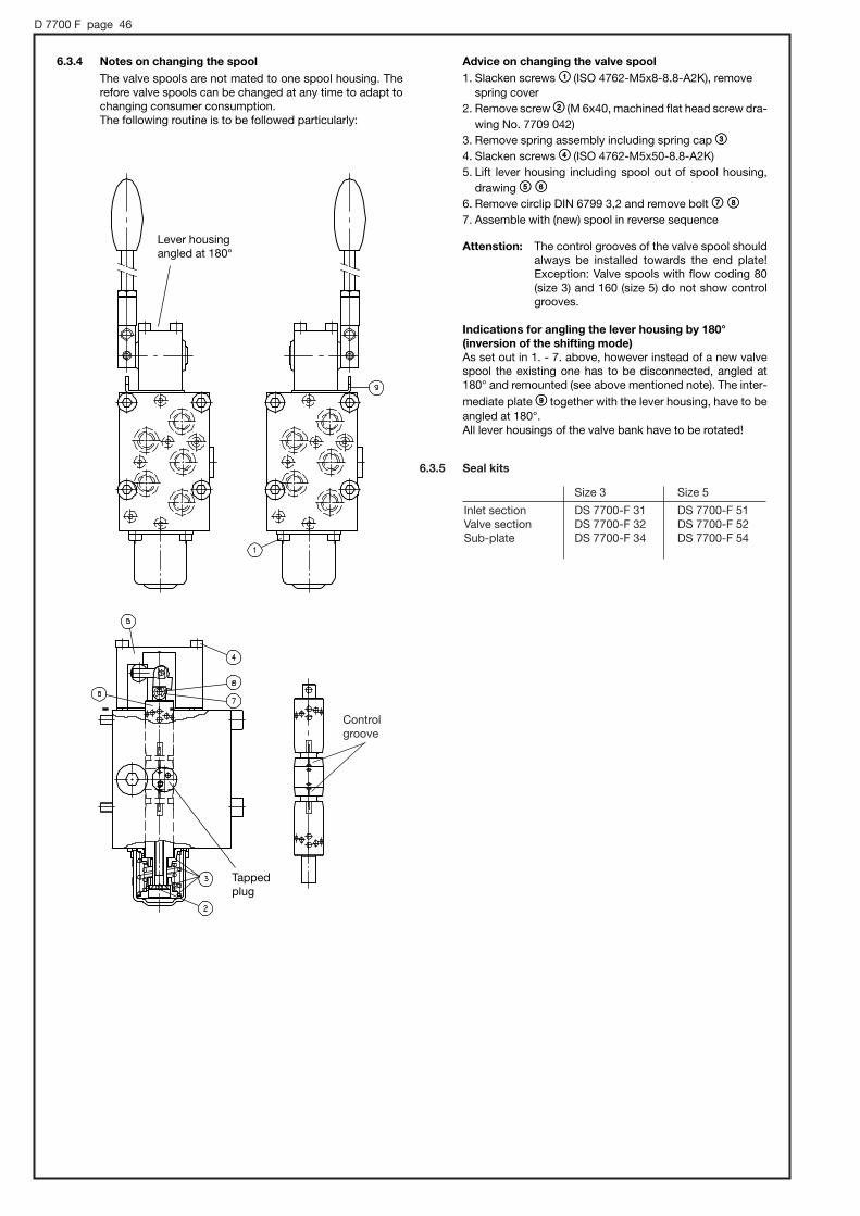
D 7700 F page 46
6.3.5 Seal kits
Size 3 Size 5
Inlet section DS 7700-F 31 DS 7700-F 51Valve section DS 7700-F 32 DS 7700-F 52Sub-plate DS 7700-F 34 DS 7700-F 54
Controlgroove
Tappedplug
6.3.4 Notes on changing the spool The valve spools are not mated to one spool housing. Therefore valve spools can be changed at any time to adapt tochanging consumer consumption. The following routine is to be followed particularly:
Advice on changing the valve spool1. Slacken screws ;; (ISO 4762-M5x8-8.8-A2K), remove
spring cover2. Remove screw << (M 6x40, machined flat head screw dra-
wing No. 7709 042)3. Remove spring assembly including spring cap ==4. Slacken screws >> (ISO 4762-M5x50-8.8-A2K) 5. Lift lever housing including spool out of spool housing,
drawing ?? @@6. Remove circlip DIN 6799 3,2 and remove bolt AA BB7. Assemble with (new) spool in reverse sequence
Attenstion: The control grooves of the valve spool should always be installed towards the end plate! Exception: Valve spools with flow coding 80 (size 3) and 160 (size 5) do not show controlgrooves.
Indications for angling the lever housing by 180°(inversion of the shifting mode) As set out in 1. - 7. above, however instead of a new valvespool the existing one has to be disconnected, angled at180° and remounted (see above mentioned note). The inter-mediate plate CC together with the lever housing, have to beangled at 180°. All lever housings of the valve bank have to be rotated!
Lever housingangled at 180°