proportional valve group - bibus menos sp. z o.o. · pdf file100/16 or pvg 120/16 build the...
TRANSCRIPT

Technical Information
Proportional Valve GroupPVG 16
powersolutions.danfoss.com

Revision history Table of revisions
Date Changed Rev
March 2016 Minor update in PVHC technical characteristics 0303
March 2016 Updated to Engineering Tomorrow design. 0302
February 2016 Drawing was updated in topic: How to select the correct spool 0301
September 2015 PVG 16 Step II 0200
March 2015 PVH, PVMD changed under Modules BF
February 2015 Seal kit added for PVB + PVM BE
December 2014 PVHC section updated BD
August 2014 PVEO pin descriptions updated BC
January 2014 Converted to Danfoss layout – DITA CMS BB
February 2013 Major layout revision, drawings change BA
October 2012 New Edition AA
Technical InformationPVG 16 Proportional Valve Group
2 | © Danfoss | March 2016 L1214235 | BC00000211en-US0303
ReferenceLiterature reference for PVG products......................................................................................................................................5
General informationPVG 16 introduction........................................................................................................................................................................ 6PVG 16 general features.................................................................................................................................................................7PVG 16 technical data..................................................................................................................................................................... 8
Safety in systemsGeneral safety considerations................................................................................................................................................... 10Control system example..............................................................................................................................................................10
PVB – basic modules (work sections)PVB work ports, interchangeable spools...............................................................................................................................12
PVB hydraulic schematics and code numbers............................................................................................................... 13PVB oil flow characteristics....................................................................................................................................................14
PVBS, main spoolFlow control, spool characteristic............................................................................................................................................ 19
PVBS hydraulic schematics and code numbers.............................................................................................................21PVBS oil flow characteristics................................................................................................................................................. 22
PVM and PVH – mechanical actuation modulesPVM and PVH general information..........................................................................................................................................25PVM actuation module................................................................................................................................................................ 25PVH actuation module................................................................................................................................................................. 26PVM/PVH hydraulic symbols and code numbers...............................................................................................................27PVM/PVH oil flow characteristics..............................................................................................................................................27
PVASPVAS design..................................................................................................................................................................................... 29Module selection guide............................................................................................................................................................... 29
PVE – electrical actuation modulesPVE features..................................................................................................................................................................................... 34
Electrical actuation...................................................................................................................................................................34Spool position output.............................................................................................................................................................35Fault monitoring....................................................................................................................................................................... 36Power save.................................................................................................................................................................................. 36PVEO/A code numbers........................................................................................................................................................... 36PVE-CI code numbers..............................................................................................................................................................36PVEA pin connector layout....................................................................................................................................................36PVEA-F pin connector layout................................................................................................................................................37PVEO pin connector layout................................................................................................................................................... 37PVE-CI pin connector layout................................................................................................................................................. 38
PVE technical data......................................................................................................................................................................... 38PVE oil flow characteristics......................................................................................................................................................... 40PVHC, high current actuation module – electrical.............................................................................................................41
PVG 16 dimensionsPVG 16................................................................................................................................................................................................44PVG 32/16......................................................................................................................................................................................... 46PVG 100/16.......................................................................................................................................................................................48PVG 120/16.......................................................................................................................................................................................50
InstallationPVG 16 installation.........................................................................................................................................................................52
Application examplesPVG 16................................................................................................................................................................................................53PVG 32/16......................................................................................................................................................................................... 54PVG 100/16.......................................................................................................................................................................................55PVG 120/16.......................................................................................................................................................................................55
Technical InformationPVG 16 Proportional Valve Group
Contents
© Danfoss | March 2016 L1214235 | BC00000211en-US0303 | 3
Hydraulic systemHydraulic system efficiency........................................................................................................................................................57
Fixed displacement system with constant flow ........................................................................................................... 57Variable displacement system with constant pressure.............................................................................................. 57Variable displacement system with load sense.............................................................................................................57
PVG 16 modules and code numbersModules and code numbers...................................................................................................................................................... 59Accessories....................................................................................................................................................................................... 63
Order specification
Technical InformationPVG 16 Proportional Valve Group
Contents
4 | © Danfoss | March 2016 L1214235 | BC00000211en-US0303
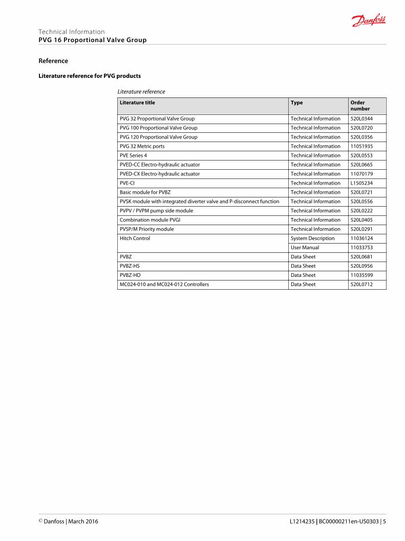
Literature reference for PVG products
Literature reference
Literature title Type Ordernumber
PVG 32 Proportional Valve Group Technical Information 520L0344
PVG 100 Proportional Valve Group Technical Information 520L0720
PVG 120 Proportional Valve Group Technical Information 520L0356
PVG 32 Metric ports Technical Information 11051935
PVE Series 4 Technical Information 520L0553
PVED-CC Electro-hydraulic actuator Technical Information 520L0665
PVED-CX Electro-hydraulic actuator Technical Information 11070179
PVE-CI Technical Information L1505234
Basic module for PVBZ Technical Information 520L0721
PVSK module with integrated diverter valve and P-disconnect function Technical Information 520L0556
PVPV / PVPM pump side module Technical Information 520L0222
Combination module PVGI Technical Information 520L0405
PVSP/M Priority module Technical Information 520L0291
Hitch Control System Description 11036124
User Manual 11033753
PVBZ Data Sheet 520L0681
PVBZ-HS Data Sheet 520L0956
PVBZ-HD Data Sheet 11035599
MC024-010 and MC024-012 Controllers Data Sheet 520L0712
Technical InformationPVG 16 Proportional Valve Group
Reference
© Danfoss | March 2016 L1214235 | BC00000211en-US0303 | 5
PVG 16 introduction
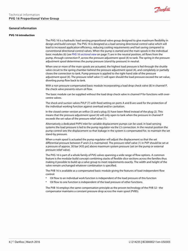
The PVG 16 is a hydraulic load sensing proportional valve group designed to give maximum flexibility indesign and build concept. The PVG 16 is designed as a load sensing directional control valve which willlead to increased application efficiency, reducing cooling requirements and fuel saving compared toconventional directional control valves. When the pump is started and the main spools in the individualbasic modules (6) (see PVG 16 sectional view on page 7) are in the neutral position, oil flows from thepump, through connection P, across the pressure adjustment spool (4) to tank. The spring in the pressureadjustment spool determines the pump pressure (stand-by pressure) in neutral.
When one or more of the main spools are actuated, the highest load pressure is fed through the shuttlevalve circuit to the spring chamber behind the pressure adjustment spool (4), and completely or partiallycloses the connection to tank. Pump pressure is applied to the right-hand side of the pressureadjustment spool (4). The pressure relief valve (1) will open should the load pressure exceed the set value,diverting pump flow back to tank.
With a non pressure-compensated basic module incorporating a load drop check valve (8) in channel P,the check valve prevents return oil flow.
The basic module can be supplied without the load drop check valve in channel P for functions with over-centre valves.
The shock and suction valves PVLP (7) with fixed setting on ports A and B are used for the protection ofthe individual working function against overload and/or cavitation.
In the closed center version an orifice (3) and a plug (5) have been fitted instead of the plug (2). Thismeans that the pressure adjustment spool (4) will only open to tank when the pressure in channel Pexceeds the set value of the pressure relief valve (1).
Alternatively a dedicated PVPV inlet for variable displacement pumps can be used. In load sensingsystems the load pressure is led to the pump regulator via the LS connection. In the neutral position thepump control sets the displacement so that leakage in the system is compensated for, to maintain the setstand-by pressure.
When a main spool is actuated the pump regulator will adjust the displacement so that the setdifferential pressure between P and LS is maintained. The pressure relief valve (1) in PVP should be set ata pressure of approx. 30 bar [435 psi] above maximum system pressure (set on the pump or externalpressure relief valve).
The PVG 16 is part of a whole family of PVG valves spanning a wide range of flow options. A commonfeature is the modular build concept combining stacks of flexible slice-sections across the families thusmaking it possible to build up a valve group to meet requirements exactly. The width and height of thevalve remain unchanged whatever combination is specified.
The PVB 16 is available as a compensated basic module giving the features of load-independent flowcontrol:• Oil flow to an individual work function is independent of the load pressure of this function• Oil flow to one function is independent of the load pressure of other functions.
The PVB 16 employs the same compensation principle as the proven technology of the PVB 32 - thecompensator maintains a constant pressure drop across the main spool (PVBS).
Technical InformationPVG 16 Proportional Valve Group
General information
6 | © Danfoss | March 2016 L1214235 | BC00000211en-US0303

PVG 16 sectional view
T P
M
LS
B
BA
1
2+3
4
5
6
7
8 V310 361.B
Legend:
1. Pressure relief valve2. Plug, open center3. Orifice, closed center4. Pressure adjustment spool5. Plug, closed center6. Main spool7. Shock and suction valve, PVLP8. Compensator or load drop check valve
(Figure shown is a load drop check valve)
PVG 16 general features
• Load sensing directional control:
‒ Proportional control of oil flow to a work function• Modular build concept:
‒ Up to 12 basic modules per PVG 16 valve group
‒ Different, interchangeable spool variants
‒ System pressure up to 350 bar [5075 psi]
‒ Several types of port connection threads
‒ Possible combination with the rest of the PVG family either PVG 32, PVG 100 or PVG 120
Technical InformationPVG 16 Proportional Valve Group
General information
© Danfoss | March 2016 L1214235 | BC00000211en-US0303 | 7

PVP and PVS from PVG 32 portfolio
The PVG 16 interfaces directly with the PVG 32 product line. The PVG 16 valve is designed to be used withthe existing PVP and PVS in the product portfolio from the PVG 32 family. When specifying a PVG 16 valvestack please refer to PVG 32 Technical Information, 520L0344 for detailed information on PVP and/or PVS.
Standard build (stack) of PVG 16 valve
Inlet section (PVP reused from the PVG 32 portfolio), 1–12 work sections (PVB) with individual flowcontrolling spools and end section (PVS reused from the PVG 32 portfolio). Each work section is actuatedby manual lever, (PVM), electrical control signal (PVE) or hydraulic control signal (PVH).
Combining PVG family into a single valve stack
The PVG 16 can be used in conjunction with the other valves in the PVG family by combining them into asingle valve stack. Hence a valve stack of PVG 32/16, PVG 100/16 or PVG 120/16 can be assembled. In aPVG 32/16 build no interface module is required as a PVG 16 slice can replace a PVG 32 slice. In a PVG100/16 or PVG 120/16 build the standard interface modules known today (PVTI and PVGI respectively) areused.
PVG 16 technical data
PVG 16 technical data
Maximum pressure Port P continuous 350 bar 1) [5075 psi]1)
Port P intermittent 400 bar [5800 psi]
Port A/B continous 380 bar [5510 psi]
Port A/B intermittent 420 bar [6090 psi]
Port T, static/dynamic 25/40 bar [365/580 psi]
Oil flow rated Port P 140/230 l/min [37/61 US gal/min]
Port A/B 65 l/min @10 bar pressure drop
[17 US gal/min @145 psi pressure drop]
Spool travel Deadband ± 1.5 mm [± 0.06 in]
Proportional range ± 5.0 mm ± 0.2 in]
Float position ± 7.5 mm [± 0.3 in]
Max. internal leakageat 100 bar [1450 psi] and21 mm2/s [102 SUS]
A/B → T without shockvalve
20 cm3/min [1.85 in3/min]
A/B → T with shock valve(system setting 30 bar [435psi]
25 cm3/min [2.15 in3/min]
Oil temperature(inlet temperature)
Recommendedtemperature
30 → 60 °C [86 → 140°F]
Minimum temperature -30 °C [-22 °F]
Maximum temperature 90 °C [194 °F]
Ambient temperature -30 → 60 °C [-22 → 140 °F]
Oil viscosity Operating range 12 - 75 mm2/s [65 - 347 SUS]
Minimum viscosity 4 mm2/s [39 SUS]
Maximum viscosity 460 mm2/s [2128 SUS]
Filtration Max. contamination (ISO4406)
23/19/16
PVM regulating range Proportional 13.9°
Float position 22.3°
Technical InformationPVG 16 Proportional Valve Group
General information
8 | © Danfoss | March 2016 L1214235 | BC00000211en-US0303
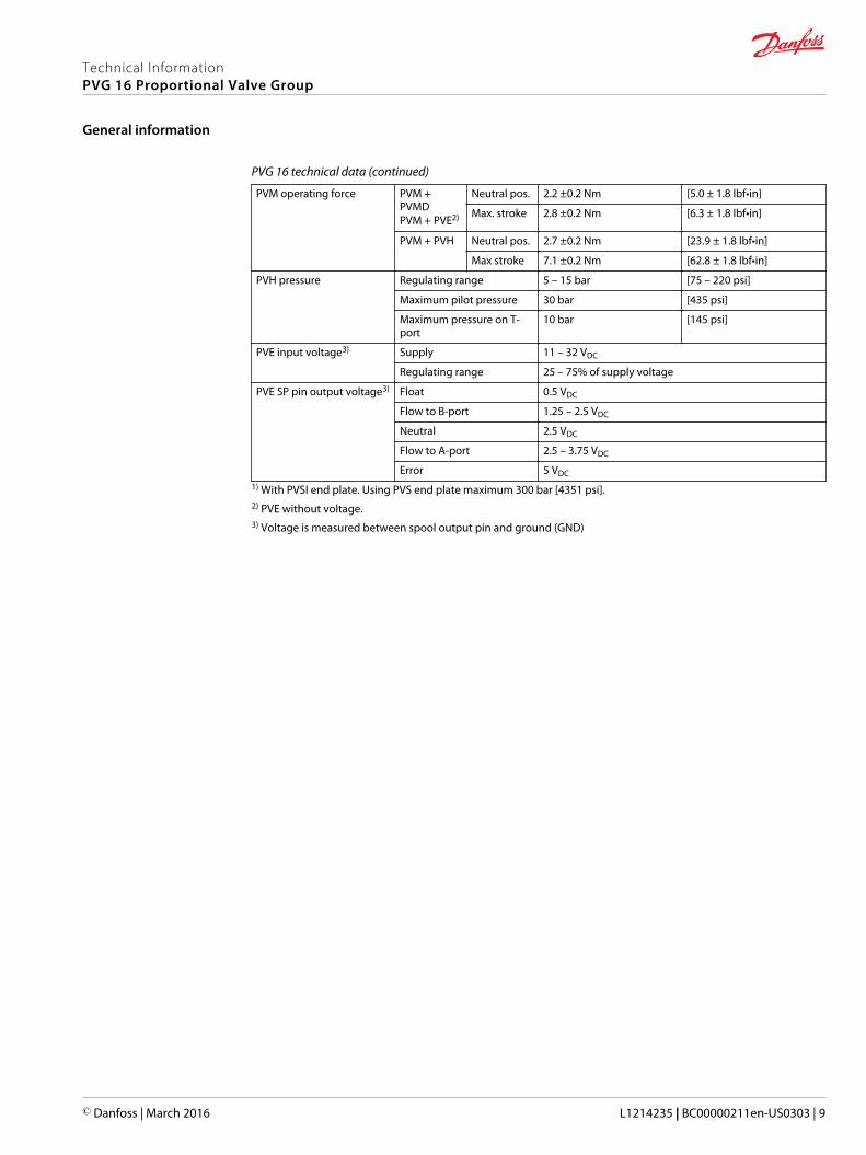
PVG 16 technical data (continued)
PVM operating force PVM +PVMDPVM + PVE2)
Neutral pos. 2.2 ±0.2 Nm [5.0 ± 1.8 lbf•in]
Max. stroke 2.8 ±0.2 Nm [6.3 ± 1.8 lbf•in]
PVM + PVH Neutral pos. 2.7 ±0.2 Nm [23.9 ± 1.8 lbf•in]
Max stroke 7.1 ±0.2 Nm [62.8 ± 1.8 lbf•in]
PVH pressure Regulating range 5 – 15 bar [75 – 220 psi]
Maximum pilot pressure 30 bar [435 psi]
Maximum pressure on T-port
10 bar [145 psi]
PVE input voltage3) Supply 11 – 32 VDC
Regulating range 25 – 75% of supply voltage
PVE SP pin output voltage3) Float 0.5 VDC
Flow to B-port 1.25 – 2.5 VDC
Neutral 2.5 VDC
Flow to A-port 2.5 – 3.75 VDC
Error 5 VDC
1) With PVSI end plate. Using PVS end plate maximum 300 bar [4351 psi].2) PVE without voltage.3) Voltage is measured between spool output pin and ground (GND)
Technical InformationPVG 16 Proportional Valve Group
General information
© Danfoss | March 2016 L1214235 | BC00000211en-US0303 | 9
General safety considerations
All types and brands of control valves, including proportional valves, can fail. Therefore, the necessaryprotection against the serious consequences of a functional failure should always be built into thesystem. For each application an assessment should be made for the consequences of the system in caseof pressure failure and uncontrolled or blocked movements.
W Warning
It is the sole responsibility of the machine manufacturer to ensure that all performance, safety, andwarning requirements of the application are met in his selection of products. The process of choosing thecontrol system and subsequent safety levels is governed by the machine directive EN 13849.
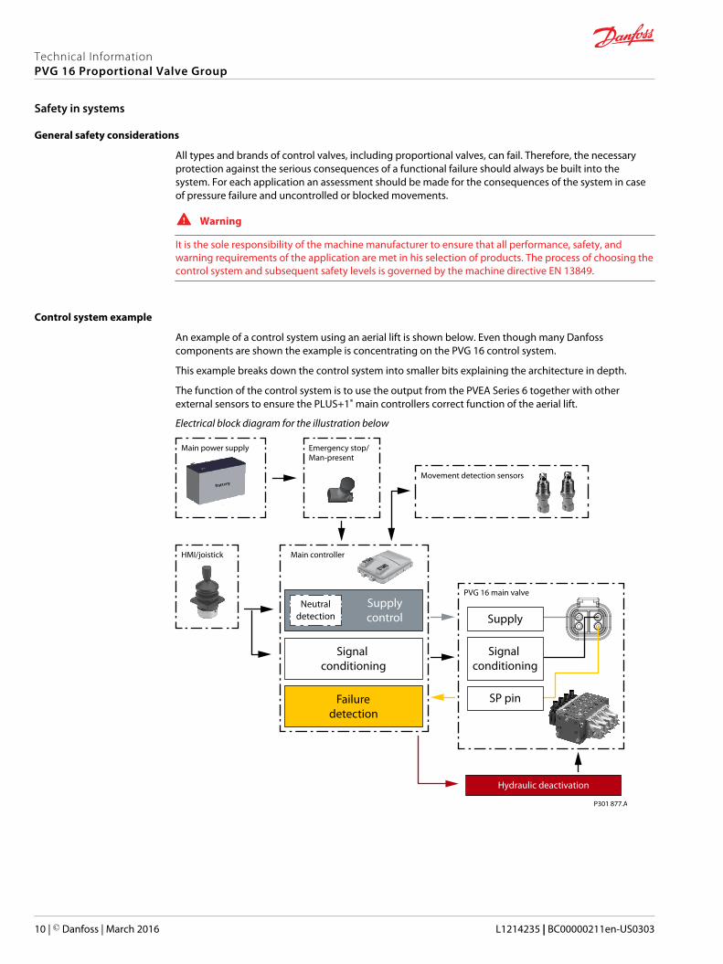
Control system example
An example of a control system using an aerial lift is shown below. Even though many Danfosscomponents are shown the example is concentrating on the PVG 16 control system.
This example breaks down the control system into smaller bits explaining the architecture in depth.
The function of the control system is to use the output from the PVEA Series 6 together with otherexternal sensors to ensure the PLUS+1® main controllers correct function of the aerial lift.
Electrical block diagram for the illustration below
Main power supply
HMI/joistick Main controller
Movement detection sensors
PVG 16 main valve
Emergency stop/Man-present
Hydraulic deactivation
Supply
SP pin
Signal conditioning
Signal conditioning
Failuredetection
Supplycontrol
Neutraldetection
P301 877.A
Technical InformationPVG 16 Proportional Valve Group
Safety in systems
10 | © Danfoss | March 2016 L1214235 | BC00000211en-US0303
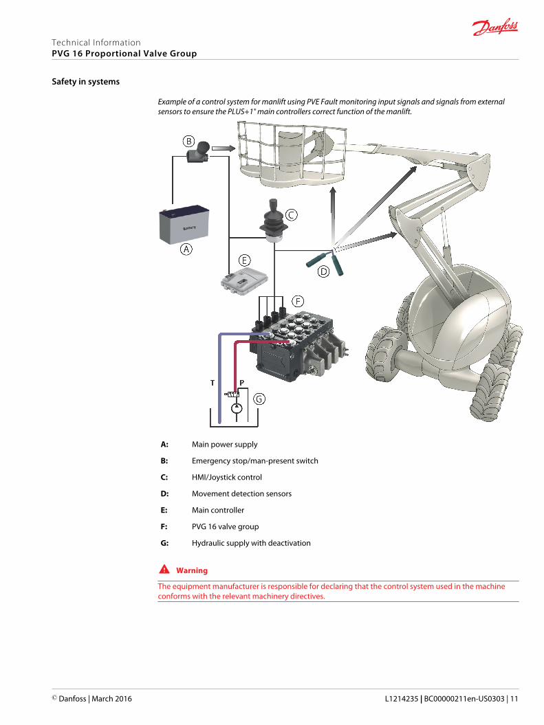
Example of a control system for manlift using PVE Fault monitoring input signals and signals from externalsensors to ensure the PLUS+1® main controllers correct function of the manlift.
A: Main power supply
B: Emergency stop/man-present switch
C: HMI/Joystick control
D: Movement detection sensors
E: Main controller
F: PVG 16 valve group
G: Hydraulic supply with deactivation
W Warning
The equipment manufacturer is responsible for declaring that the control system used in the machineconforms with the relevant machinery directives.
Technical InformationPVG 16 Proportional Valve Group
Safety in systems
© Danfoss | March 2016 L1214235 | BC00000211en-US0303 | 11
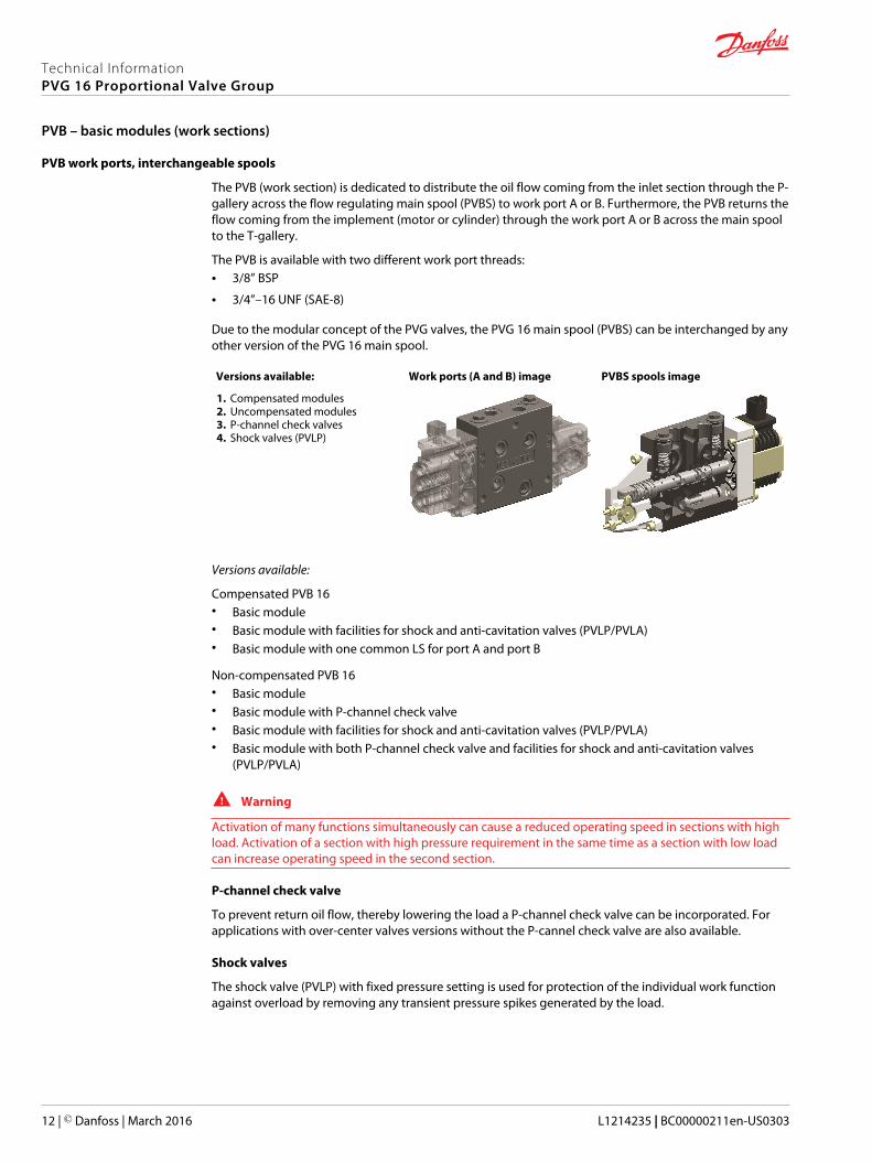
PVB work ports, interchangeable spools
The PVB (work section) is dedicated to distribute the oil flow coming from the inlet section through the P-gallery across the flow regulating main spool (PVBS) to work port A or B. Furthermore, the PVB returns theflow coming from the implement (motor or cylinder) through the work port A or B across the main spoolto the T-gallery.
The PVB is available with two different work port threads:• 3/8” BSP
• 3/4”–16 UNF (SAE-8)
Due to the modular concept of the PVG valves, the PVG 16 main spool (PVBS) can be interchanged by anyother version of the PVG 16 main spool.
Versions available: Work ports (A and B) image PVBS spools image
1. Compensated modules2. Uncompensated modules3. P-channel check valves4. Shock valves (PVLP)
Versions available:
Compensated PVB 16• Basic module• Basic module with facilities for shock and anti-cavitation valves (PVLP/PVLA)• Basic module with one common LS for port A and port B
Non-compensated PVB 16• Basic module• Basic module with P-channel check valve• Basic module with facilities for shock and anti-cavitation valves (PVLP/PVLA)• Basic module with both P-channel check valve and facilities for shock and anti-cavitation valves
(PVLP/PVLA)
W Warning
Activation of many functions simultaneously can cause a reduced operating speed in sections with highload. Activation of a section with high pressure requirement in the same time as a section with low loadcan increase operating speed in the second section.
P-channel check valve
To prevent return oil flow, thereby lowering the load a P-channel check valve can be incorporated. Forapplications with over-center valves versions without the P-cannel check valve are also available.
Shock valves
The shock valve (PVLP) with fixed pressure setting is used for protection of the individual work functionagainst overload by removing any transient pressure spikes generated by the load.
Technical InformationPVG 16 Proportional Valve Group
PVB – basic modules (work sections)
12 | © Danfoss | March 2016 L1214235 | BC00000211en-US0303

PVB hydraulic schematics and code numbers
PVB Compensated Basic Modules – hydraulic schematics and code numbers
Symbol PVB description / Port Code number
P301 831.A
201
B
A
Compensated basic module 3/8” BSP 11130976
3/4” -16 UNF(SAE-8)
11130977
201
P301 832.A
B
A
Compensated basic moduleWith facilities for shock andanti-cavitataion valves (PVLP/PVLA
3/8” BSP 11130978
3/4” -16 UNF(SAE-8)
11130979
P301 833.A
201
B
A
Compensated basic moduleWith one common adjustableLS valve for port A and port B
3/8” BSP 11130982
3/4” -16 UNF(SAE-8)
11130983
PVB Non-compensated Basic Modules – hydraulic schematics and code numbers
Symbol PVB description / Port Code number
V310 412.A
Basic work moduleWithout P-channel check valveWithout shock valve
3/8” BSP 11101421
3/4” -16 UNF(SAE-8)
11101423
Basic work moduleWithout P-channel check valveWith shock valve
3/8” BSP 11106754
3/4” -16 UNF(SAE-8)
11106755
Technical InformationPVG 16 Proportional Valve Group
PVB – basic modules (work sections)
© Danfoss | March 2016 L1214235 | BC00000211en-US0303 | 13
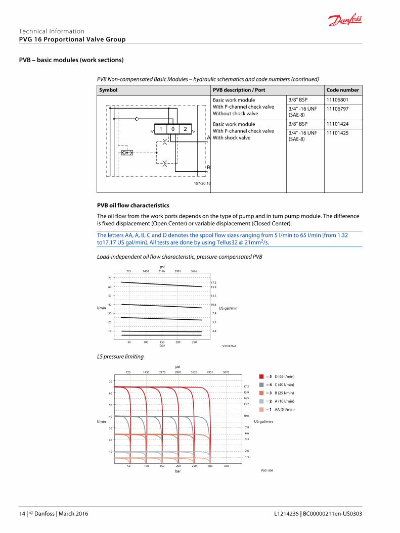
PVB Non-compensated Basic Modules – hydraulic schematics and code numbers (continued)
Symbol PVB description / Port Code number
Basic work moduleWith P-channel check valveWithout shock valve
3/8” BSP 11106801
3/4” -16 UNF(SAE-8)
11106797
Basic work moduleWith P-channel check valveWith shock valve
3/8” BSP 11101424
3/4” -16 UNF(SAE-8)
11101425
PVB oil flow characteristics
The oil flow from the work ports depends on the type of pump and in turn pump module. The differenceis fixed displacement (Open Center) or variable displacement (Closed Center).
The letters AA, A, B, C and D denotes the spool flow sizes ranging from 5 l/min to 65 l/min [from 1.32to17.17 US gal/min]. All tests are done by using Tellus32 @ 21mm2/s.
Load-independent oil flow characteristic, pressure-compensated PVB
10
20
30
40
50
60
70
50 100 150 200 250
l/min US gal/min
bar
psi
13.2
2.6
5.3
7.9
10.6
15.917.2
725 1450 2176 2901 3626
V310476.A
LS pressure limiting
10
20
30
40
50
60
70
50 100 150 200 250 300 350
l/min US gal/min
bar
psi
13.2
2.6
1.3
5.3
7.9
6.6
10.6
15.9
14.5
17.2
725 1450 2176 2901 3626 4351 5076
P301 809
= 5 D (65 l/min)
= 4 C (40 l/min)
= 3 B (25 l/min)
= 2 A (10 l/min)
= 1 AA (5 l/min)
Technical InformationPVG 16 Proportional Valve Group
PVB – basic modules (work sections)
14 | © Danfoss | March 2016 L1214235 | BC00000211en-US0303

Oil flow as a function of spool travel with Open Center PVP
AA
A
B
C
D
1
1
6
6
10
20
30
40
50
60
70
mm1 2 3 4 5
[10]
[15]
[5]
Ql/min [US gal/min]
PVM
[in][0.04] [0.08] [0.12] [0.16] [0.2]P005 595E.B
The flow is dependent on the supplied flow, Qp.The characteristics apply to supply oil of 130 l/min [34.3 US gal/min].The numbers 1 and 6 refer to the position of the PVB in the valve stack.
Oil flow as a function of spool travel with Closed Center PVP
AA
A
B
C
D
1
1
6
6
10
20
30
40
50
60
70
[10]
[15]
[5]
Ql/min [US gal/min]
PVMmm1 2 3 4 5[in][0.04] [0.08] [0.12] [0.16] [0.2]
80
[20]
P005 596E.B
Technical InformationPVG 16 Proportional Valve Group
PVB – basic modules (work sections)
© Danfoss | March 2016 L1214235 | BC00000211en-US0303 | 15
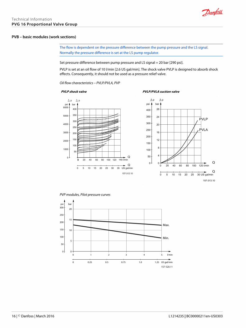
The flow is dependent on the pressure difference between the pump pressure and the LS signal.Normally the pressure difference is set at the LS pump regulator.
Set pressure difference between pump pressure and LS signal = 20 bar [290 psi].
PVLP is set at an oil flow of 10 l/min [2.6 US gal/min]. The shock valve PVLP is designed to absorb shockeffects. Consequently, it should not be used as a pressure relief valve.
Oil flow characteristics – PVLP/PVLA, PVP
PVLP shock valve PVLP/PVLA suction valve
PVP modules, Pilot pressure curves
157-520.11
00 1 2 l/min
bar
20
10
15
5
3 4 5
psi
50
100
150
200
250
300
0
0 0.25 0.5 0.75 1.0 1.25 US gal/min
Max.
Min.
Technical InformationPVG 16 Proportional Valve Group
PVB – basic modules (work sections)
16 | © Danfoss | March 2016 L1214235 | BC00000211en-US0303
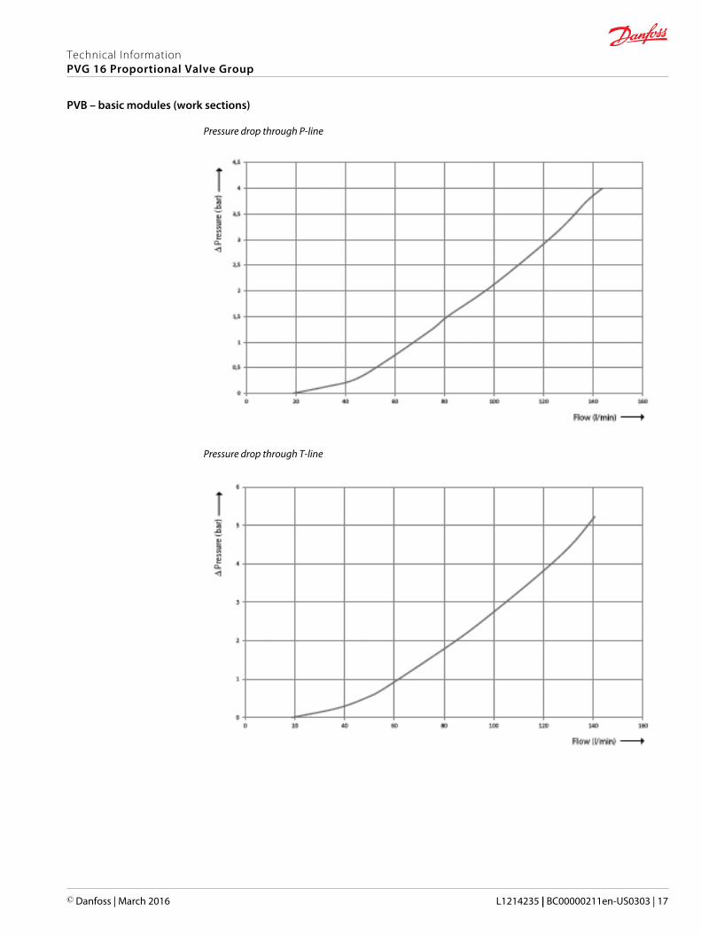
Pressure drop through P-line
Pressure drop through T-line
Technical InformationPVG 16 Proportional Valve Group
PVB – basic modules (work sections)
© Danfoss | March 2016 L1214235 | BC00000211en-US0303 | 17

Pressure drop through Pp-line
Technical InformationPVG 16 Proportional Valve Group
PVB – basic modules (work sections)
18 | © Danfoss | March 2016 L1214235 | BC00000211en-US0303
Flow control, spool characteristic
The spool is directly controlling the oil flow to and from the work ports. This flow is directly proportionalwith the spool travel. The spool travel is made up of 1.5 mm [0.06 in] dead band and 3.5 mm [0.14 in]active region in each direction giving 0-full flow. An additional 2.5 mm [0.1 in] travel in one direction inorder to accommodate float functionality can be used dependant on choice of PVM.
Flow control
The spools are designed in such a way that the oil flow coming from the pump to the work ports arecontrolled by the spool travel. When the spool is moved it forms a variable orifice between the P-galleryand one work port and between the other work port and the T-gallery. The size of the orifice is directlylinked to the traveled distance of the spool.
Spools characteristic
The spools characteristic is linear with a soft start. The spool will have a progressive behavior from neutralto 10% of the full flow. From there it will be linear all the way to maximum flow.
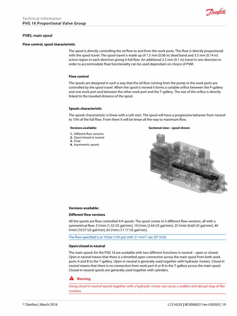
Versions available: Sectional view – spool shown
1. Different flow versions2. Open/closed in neutral3. Float4. Asymmetric spools
Versions available:
Different flow versions
All the spools are flow controlled 4/4 spools. The spool comes in 5 different flow versions, all with asymmetrical flow: 5 l/min [1.32 US gal/min], 10 l/min [2.64 US gal/min], 25 l/min [6.60 US gal/min], 40l/min [10.57 US gal/min], 65 l/min [17.17 US gal/min].
The flow specified is at 10 bar [145 psi] with 21 mm2/ sec [97 SUS].
Open/closed in neutral
The main spools for the PVG 16 are available with two different functions in neutral – open or closed.Open in neutral means that there is a throttled open connection across the main spool from both workports A and B to the T-gallery. Open in neutral is generally used together with hydraulic motors. Closed inneutral means that there is no connection from work port A or B to the T-gallery across the main spool.Closed in neutral spools are generally used together with cylinders.
W Warning
Using closed in neutral spools together with a hydraulic motor can cause a sudden and abrupt stop of therotation.
Technical InformationPVG 16 Proportional Valve Group
PVBS, main spool
© Danfoss | March 2016 L1214235 | BC00000211en-US0303 | 19
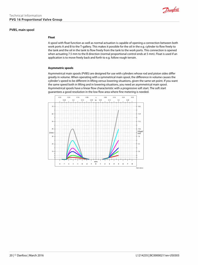
Float
A spool with float function as well as normal actuation is capable of opening a connection between bothwork ports A and B to the T-gallery. This makes it possible for the oil in the e.g. cylinder to flow freely tothe tank and the oil in the tank to flow freely from the tank to the work ports. This connection is openedwhen actuating 7.5 mm to the B direction (normal proportional control ends at 5 mm). Float is used if anapplication is to move freely back and forth to e.g. follow rough terrain.
Asymmetric spools
Asymmetrical main spools (PVBS) are designed for use with cylinders whose rod and piston sides differgreatly in volume. When operating with a symmetrical main spool, the difference in volume causes thecylinder’s speed to be different in lifting versus lowering situations, given the same set point. If you wantthe same speed both in lifting and in lowering situations, you need an asymmetrical main spool.Asymmetrical spools have a linear flow characteristic with a progressive soft start. The soft startguarantees a good resolution in the low flow area where fine metering is needed.
10
20
30
40
50
60
70
mm
l/minUSgal/min
0
13.2
2.6
5.3
7.9
10.6
15.9
18.5
in-0.32
0.280.04-0.04-0.12 0.12 0.2-0.2-0.28
0.320.240.160.08-0.08-0.16-0.24
-8 -7 -6 -5 -4 -3-3 -2-2 -1-1 00 11 22 33 44 55 66 77 88
P301 835.A
Technical InformationPVG 16 Proportional Valve Group
PVBS, main spool
20 | © Danfoss | March 2016 L1214235 | BC00000211en-US0303
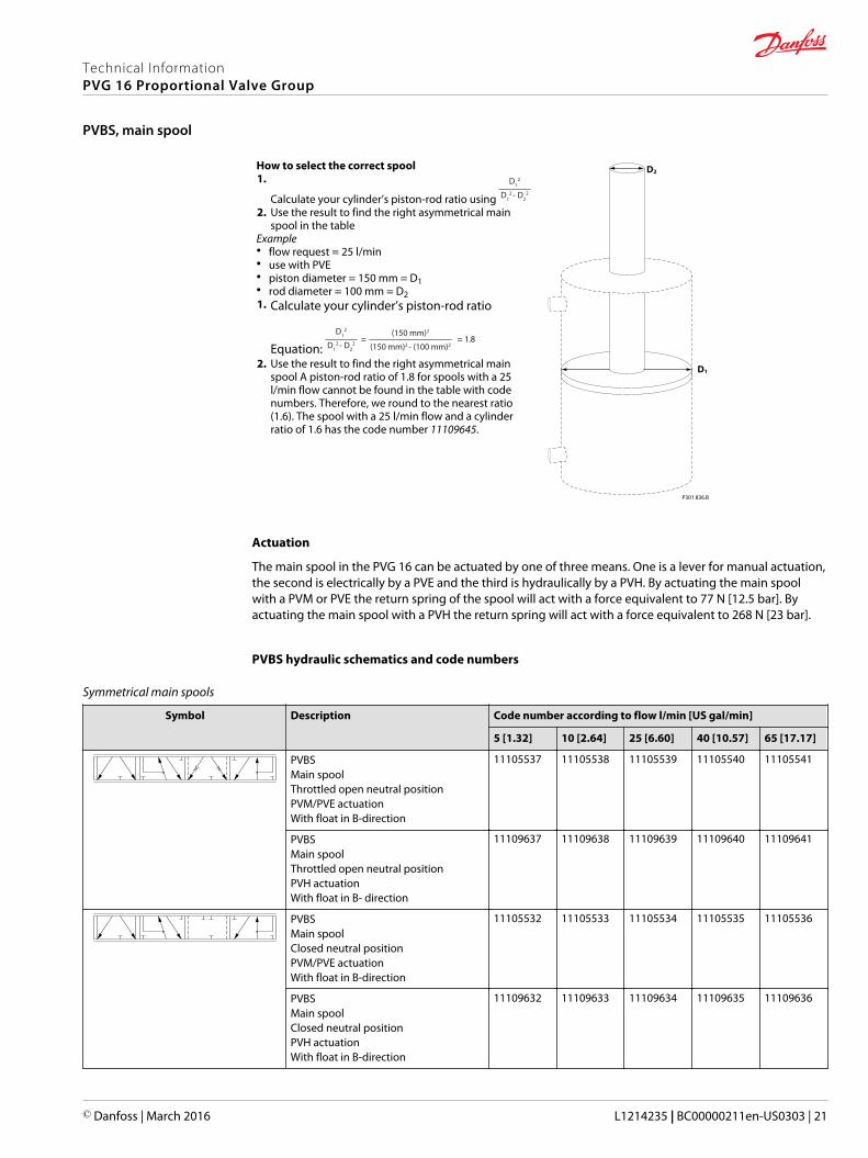
How to select the correct spool1.
Calculate your cylinder’s piston-rod ratio using
D12
D12 - D2
2
2. Use the result to find the right asymmetrical mainspool in the table
Example• flow request = 25 l/min• use with PVE• piston diameter = 150 mm = D1• rod diameter = 100 mm = D21. Calculate your cylinder’s piston-rod ratio
Equation: D1
2
D12 - D2
2
(150 mm)2
(150 mm)2 - (100 mm)2= = 1.8
2. Use the result to find the right asymmetrical mainspool A piston-rod ratio of 1.8 for spools with a 25l/min flow cannot be found in the table with codenumbers. Therefore, we round to the nearest ratio(1.6). The spool with a 25 l/min flow and a cylinderratio of 1.6 has the code number 11109645.
P301 836.B
D1
D2
Actuation
The main spool in the PVG 16 can be actuated by one of three means. One is a lever for manual actuation,the second is electrically by a PVE and the third is hydraulically by a PVH. By actuating the main spoolwith a PVM or PVE the return spring of the spool will act with a force equivalent to 77 N [12.5 bar]. Byactuating the main spool with a PVH the return spring will act with a force equivalent to 268 N [23 bar].
PVBS hydraulic schematics and code numbers
Symmetrical main spools
Symbol Description Code number according to flow l/min [US gal/min]
5 [1.32] 10 [2.64] 25 [6.60] 40 [10.57] 65 [17.17]
PVBSMain spoolThrottled open neutral positionPVM/PVE actuationWith float in B-direction
11105537 11105538 11105539 11105540 11105541
PVBSMain spoolThrottled open neutral positionPVH actuationWith float in B- direction
11109637 11109638 11109639 11109640 11109641
PVBSMain spoolClosed neutral positionPVM/PVE actuationWith float in B-direction
11105532 11105533 11105534 11105535 11105536
PVBSMain spoolClosed neutral positionPVH actuationWith float in B-direction
11109632 11109633 11109634 11109635 11109636
Technical InformationPVG 16 Proportional Valve Group
PVBS, main spool
© Danfoss | March 2016 L1214235 | BC00000211en-US0303 | 21
Asymmetrical main spools
Symbol Description Code number according to flow l/min [US gal/min]
5/2.5[1.32/0.66]
10/5[2.64/1.32]
25/10[6.60/2.64]
25/15[6.60/3.96]
40/15[10.57/3.96]
40/25[10.57/6.60]
Cylinder ratio 2.0 2.0 2.5 1.6 2.7 1.6
PVBSMain spoolClosed neutral positionPVM/PVE actuationWith float in B-direction
11109642 11109643 11109644 11109645 11109646 11109647
PVBSMain spoolClosed neutral positionPVH actuationWith float in B- direction
11146752 11146753 11146754 11146755 11146756 11146757
PVBS oil flow characteristics
The letters AA, A, B, C and D denotes the spool flow sizes ranging from 5 l/min to 65 l/min [1.32 to17.17US gal/min]. All tests are done by using Tellus32 @ 21mm2/s.
Technical InformationPVG 16 Proportional Valve Group
PVBS, main spool
22 | © Danfoss | March 2016 L1214235 | BC00000211en-US0303

Oil flow as a function of spool travel
Technical InformationPVG 16 Proportional Valve Group
PVBS, main spool
© Danfoss | March 2016 L1214235 | BC00000211en-US0303 | 23

Pressure drop to tank for open spool in neutral300
250
200
150
100
50
0
Flow (l/min)
0 10 20 30 40 50 60
D P
ress
ure
(bar
) AA A B C D
P005 601E
Pressure drop at full spool stroke
50
40
30
20
10
00 20 40 60 80 100 120
Flow (l/min)
P005 912
∆ P
ress
ure
(bar
)
Pressure drop in float
200
150
100
50
0
Flow (l/min)
P005 911
∆ P
ress
ure
(bar
)
0 20 40 60 80 100 120 140
AA A
B
C
D
Technical InformationPVG 16 Proportional Valve Group
PVBS, main spool
24 | © Danfoss | March 2016 L1214235 | BC00000211en-US0303
PVM and PVH general information
The PVM and PVH are two ways of mechanically controlling the flow from the work ports. The flow iscontrolled either by an operator using a lever or from a distance by a hydraulic joystick.
These are types of mechanical actuation modules for the PVG 16:• PVM – a fully manual lever controlled module
• PVH – a hydraulic controlled module
• PVMD – cover
Versions available:
1. PVM with float control2. PVM without adjustment screws3. PVM with adjustment screws
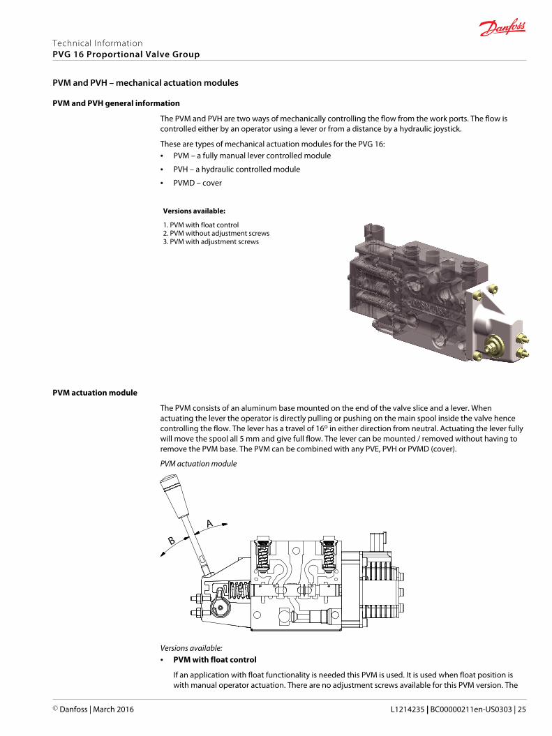
PVM actuation module
The PVM consists of an aluminum base mounted on the end of the valve slice and a lever. Whenactuating the lever the operator is directly pulling or pushing on the main spool inside the valve hencecontrolling the flow. The lever has a travel of 16o in either direction from neutral. Actuating the lever fullywill move the spool all 5 mm and give full flow. The lever can be mounted / removed without having toremove the PVM base. The PVM can be combined with any PVE, PVH or PVMD (cover).
PVM actuation module
A
B
Versions available:• PVM with float control
If an application with float functionality is needed this PVM is used. It is used when float position iswith manual operator actuation. There are no adjustment screws available for this PVM version. The
Technical InformationPVG 16 Proportional Valve Group
PVM and PVH – mechanical actuation modules
© Danfoss | March 2016 L1214235 | BC00000211en-US0303 | 25
setting of this PVM is 5 mm spool travel in the A direction and 7.5 mm spool travel in the B directiongiving float.
• PVM without adjustment screws
The standard PVM without adjustment screws will allow a spool travel of 5 mm in either direction. Fulllever movement to one side will give full flow to the work ports. When the spool is moved 5mm it willstop due to a mechanical limitation build into the PVM base.
• PVM with adjustment screws
The standard PVM without adjustment screws will allow a spool travel of 5 mm in either direction. Thespool travel in either direction can be limited by the adjustment screws. This will limit the flow out ofthe work ports thereby reducing the speed of an application.
The spool travel is adjusted by first loosening the nut then adjusting the pinol screw. After adjustmentthe nut must be tightened again.
Technical characteristics for PVM
V310367.A
8 ±1 N•m[71±9 lbf•in]
10 [0.40]
3 [0.12]
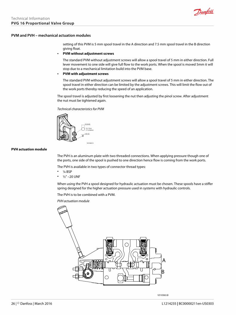
PVH actuation module
The PVH is an aluminum plate with two threaded connections. When applying pressure though one ofthe ports, one side of the spool is pushed to one direction hence flow is coming from the work ports.
The PVH is available in two types of connector thread types:• ¼ BSP• ½” –20 UNF
When using the PVH a spool designed for hydraulic actuation must be chosen. These spools have a stifferspring designed for the higher actuation pressure used in systems with hydraulic controls.
The PVH is to be combined with a PVM.
PVH actuation module
A
B
V310363.B
Technical InformationPVG 16 Proportional Valve Group
PVM and PVH – mechanical actuation modules
26 | © Danfoss | March 2016 L1214235 | BC00000211en-US0303
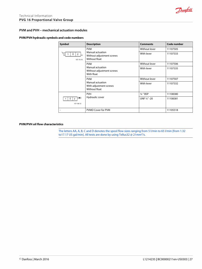
PVM/PVH hydraulic symbols and code numbers
Symbol Description Comments Code number
PVMManual actuationWithout adjustment screwsWithout float
Without lever 11107505
With lever 11107333
PVMManual actuationWithout adjustment screwsWith float
Without lever 11107506
With lever 11107335
PVMManual actuationWith adjustment screwsWithout float
Without lever 11107507
With lever 11107332
PVHHydraulic cover
¼ “ BSP 11108380
UNF ½” -20 11108381
- PVMD Cover for PVM 11105518
PVM/PVH oil flow characteristics
The letters AA, A, B, C and D denotes the spool flow sizes ranging from 5 l/min to 65 l/min [from 1.32to17.17 US gal/min]. All tests are done by using Tellus32 @ 21mm2/s.
Technical InformationPVG 16 Proportional Valve Group
PVM and PVH – mechanical actuation modules
© Danfoss | March 2016 L1214235 | BC00000211en-US0303 | 27
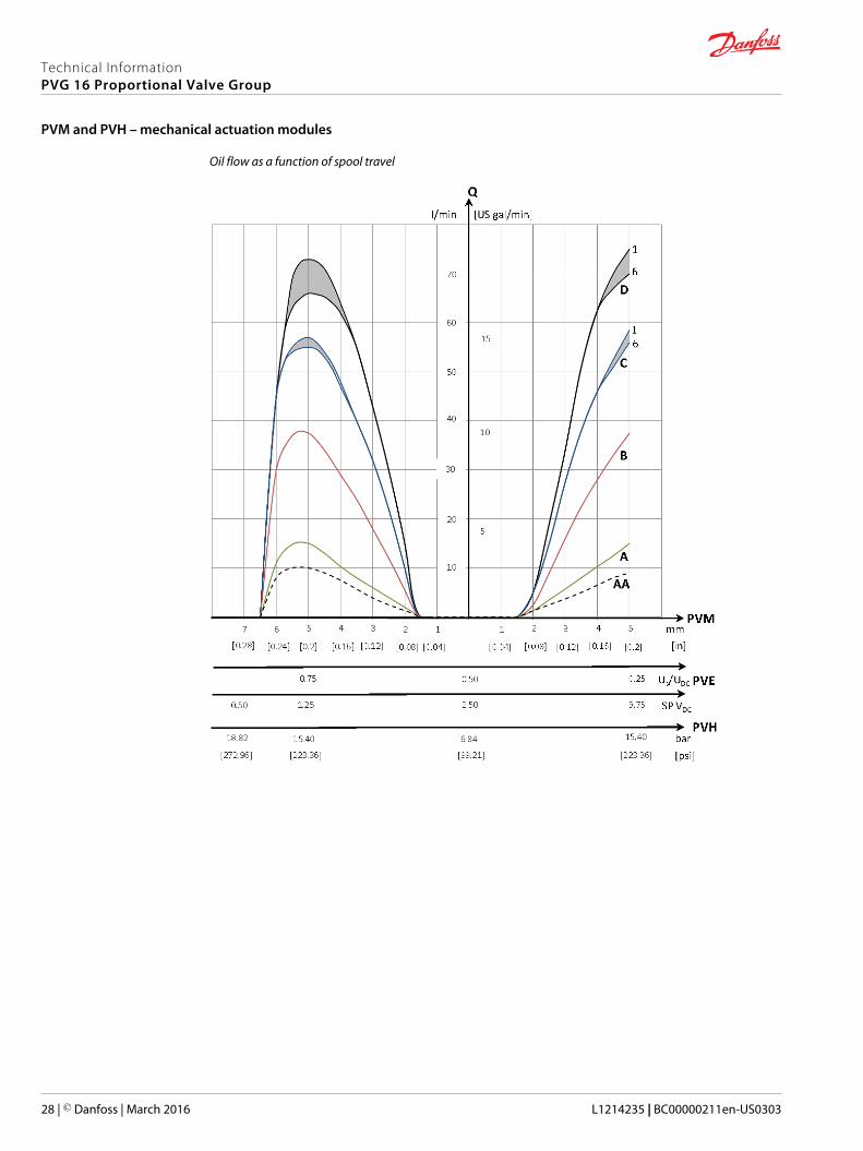
Oil flow as a function of spool travel
Technical InformationPVG 16 Proportional Valve Group
PVM and PVH – mechanical actuation modules
28 | © Danfoss | March 2016 L1214235 | BC00000211en-US0303
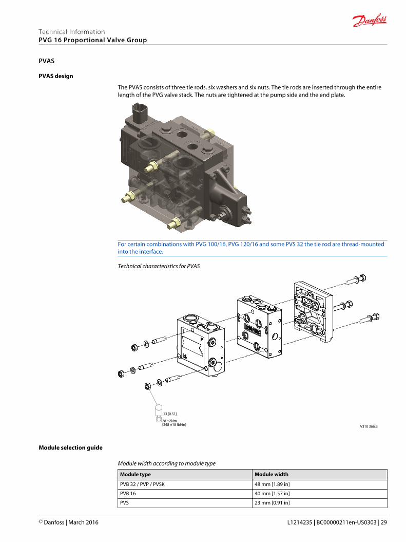
PVAS design
The PVAS consists of three tie rods, six washers and six nuts. The tie rods are inserted through the entirelength of the PVG valve stack. The nuts are tightened at the pump side and the end plate.
For certain combinations with PVG 100/16, PVG 120/16 and some PVS 32 the tie rod are thread-mountedinto the interface.
Technical characteristics for PVAS
h28 ±2Nm[248 ±18 lbf•in] V310 366.B
13 [0.51]
Module selection guide
Module width according to module type
Module type Module width
PVB 32 / PVP / PVSK 48 mm [1.89 in]
PVB 16 40 mm [1.57 in]
PVS 23 mm [0.91 in]
Technical InformationPVG 16 Proportional Valve Group
PVAS
© Danfoss | March 2016 L1214235 | BC00000211en-US0303 | 29
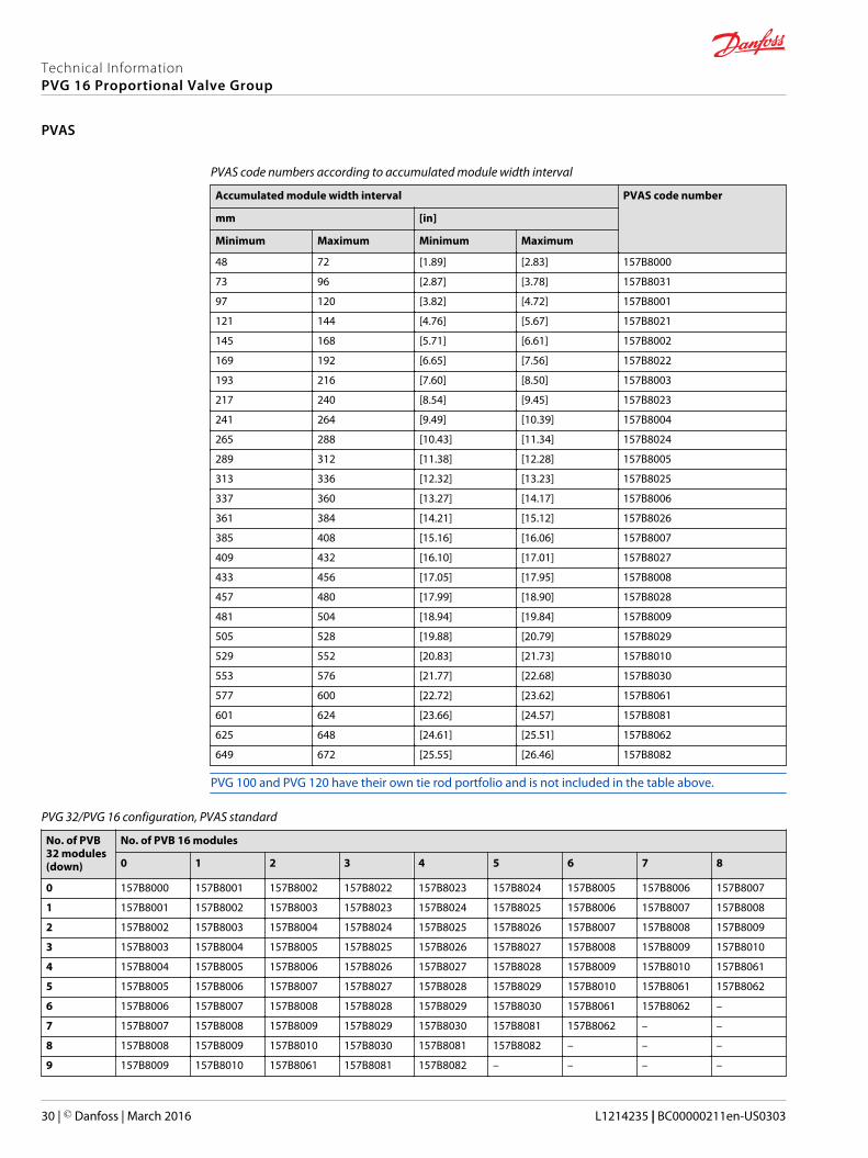
PVAS code numbers according to accumulated module width interval
Accumulated module width interval PVAS code number
mm [in]
Minimum Maximum Minimum Maximum
48 72 [1.89] [2.83] 157B8000
73 96 [2.87] [3.78] 157B8031
97 120 [3.82] [4.72] 157B8001
121 144 [4.76] [5.67] 157B8021
145 168 [5.71] [6.61] 157B8002
169 192 [6.65] [7.56] 157B8022
193 216 [7.60] [8.50] 157B8003
217 240 [8.54] [9.45] 157B8023
241 264 [9.49] [10.39] 157B8004
265 288 [10.43] [11.34] 157B8024
289 312 [11.38] [12.28] 157B8005
313 336 [12.32] [13.23] 157B8025
337 360 [13.27] [14.17] 157B8006
361 384 [14.21] [15.12] 157B8026
385 408 [15.16] [16.06] 157B8007
409 432 [16.10] [17.01] 157B8027
433 456 [17.05] [17.95] 157B8008
457 480 [17.99] [18.90] 157B8028
481 504 [18.94] [19.84] 157B8009
505 528 [19.88] [20.79] 157B8029
529 552 [20.83] [21.73] 157B8010
553 576 [21.77] [22.68] 157B8030
577 600 [22.72] [23.62] 157B8061
601 624 [23.66] [24.57] 157B8081
625 648 [24.61] [25.51] 157B8062
649 672 [25.55] [26.46] 157B8082
PVG 100 and PVG 120 have their own tie rod portfolio and is not included in the table above.
PVG 32/PVG 16 configuration, PVAS standard
No. of PVB32 modules(down)
No. of PVB 16 modules
0 1 2 3 4 5 6 7 8
0 157B8000 157B8001 157B8002 157B8022 157B8023 157B8024 157B8005 157B8006 157B8007
1 157B8001 157B8002 157B8003 157B8023 157B8024 157B8025 157B8006 157B8007 157B8008
2 157B8002 157B8003 157B8004 157B8024 157B8025 157B8026 157B8007 157B8008 157B8009
3 157B8003 157B8004 157B8005 157B8025 157B8026 157B8027 157B8008 157B8009 157B8010
4 157B8004 157B8005 157B8006 157B8026 157B8027 157B8028 157B8009 157B8010 157B8061
5 157B8005 157B8006 157B8007 157B8027 157B8028 157B8029 157B8010 157B8061 157B8062
6 157B8006 157B8007 157B8008 157B8028 157B8029 157B8030 157B8061 157B8062 –
7 157B8007 157B8008 157B8009 157B8029 157B8030 157B8081 157B8062 – –
8 157B8008 157B8009 157B8010 157B8030 157B8081 157B8082 – – –
9 157B8009 157B8010 157B8061 157B8081 157B8082 – – – –
Technical InformationPVG 16 Proportional Valve Group
PVAS
30 | © Danfoss | March 2016 L1214235 | BC00000211en-US0303
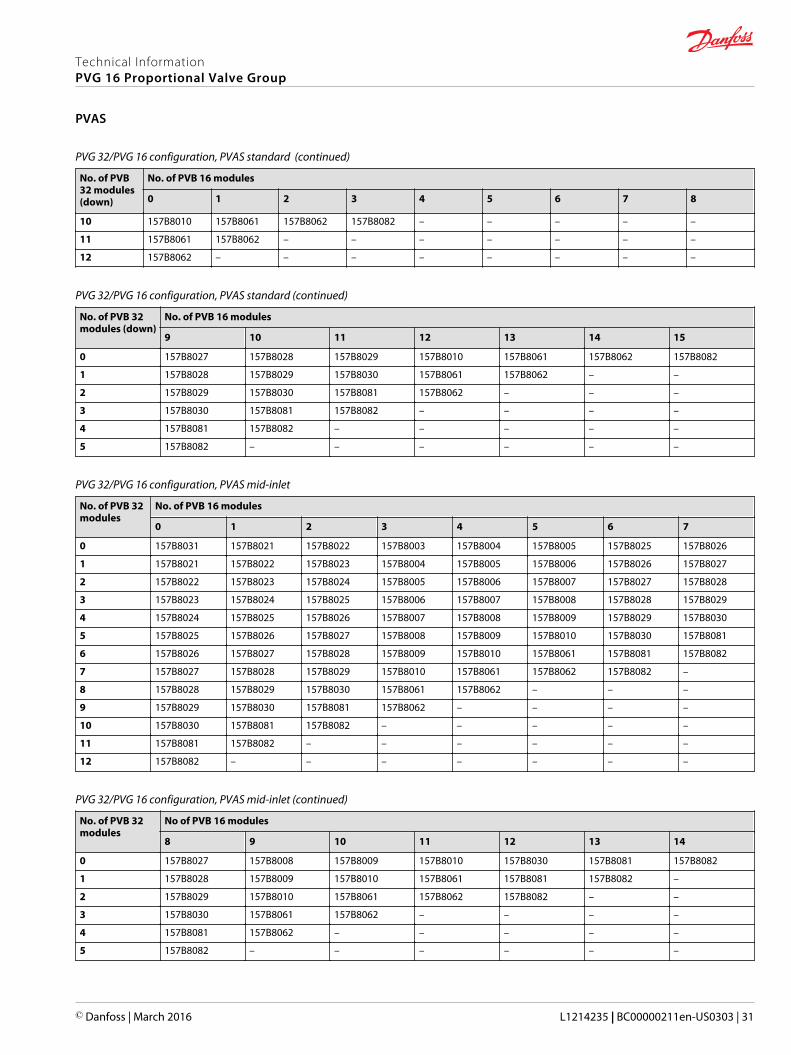
PVG 32/PVG 16 configuration, PVAS standard (continued)
No. of PVB32 modules(down)
No. of PVB 16 modules
0 1 2 3 4 5 6 7 8
10 157B8010 157B8061 157B8062 157B8082 – – – – –
11 157B8061 157B8062 – – – – – – –
12 157B8062 – – – – – – – –
PVG 32/PVG 16 configuration, PVAS standard (continued)
No. of PVB 32modules (down)
No. of PVB 16 modules
9 10 11 12 13 14 15
0 157B8027 157B8028 157B8029 157B8010 157B8061 157B8062 157B8082
1 157B8028 157B8029 157B8030 157B8061 157B8062 – –
2 157B8029 157B8030 157B8081 157B8062 – – –
3 157B8030 157B8081 157B8082 – – – –
4 157B8081 157B8082 – – – – –
5 157B8082 – – – – – –
PVG 32/PVG 16 configuration, PVAS mid-inlet
No. of PVB 32modules
No. of PVB 16 modules
0 1 2 3 4 5 6 7
0 157B8031 157B8021 157B8022 157B8003 157B8004 157B8005 157B8025 157B8026
1 157B8021 157B8022 157B8023 157B8004 157B8005 157B8006 157B8026 157B8027
2 157B8022 157B8023 157B8024 157B8005 157B8006 157B8007 157B8027 157B8028
3 157B8023 157B8024 157B8025 157B8006 157B8007 157B8008 157B8028 157B8029
4 157B8024 157B8025 157B8026 157B8007 157B8008 157B8009 157B8029 157B8030
5 157B8025 157B8026 157B8027 157B8008 157B8009 157B8010 157B8030 157B8081
6 157B8026 157B8027 157B8028 157B8009 157B8010 157B8061 157B8081 157B8082
7 157B8027 157B8028 157B8029 157B8010 157B8061 157B8062 157B8082 –
8 157B8028 157B8029 157B8030 157B8061 157B8062 – – –
9 157B8029 157B8030 157B8081 157B8062 – – – –
10 157B8030 157B8081 157B8082 – – – – –
11 157B8081 157B8082 – – – – – –
12 157B8082 – – – – – – –
PVG 32/PVG 16 configuration, PVAS mid-inlet (continued)
No. of PVB 32modules
No of PVB 16 modules
8 9 10 11 12 13 14
0 157B8027 157B8008 157B8009 157B8010 157B8030 157B8081 157B8082
1 157B8028 157B8009 157B8010 157B8061 157B8081 157B8082 –
2 157B8029 157B8010 157B8061 157B8062 157B8082 – –
3 157B8030 157B8061 157B8062 – – – –
4 157B8081 157B8062 – – – – –
5 157B8082 – – – – – –
Technical InformationPVG 16 Proportional Valve Group
PVAS
© Danfoss | March 2016 L1214235 | BC00000211en-US0303 | 31

PVG 32/PVG 16 configuration, PVAS PVSK
No. of PVB 32modules
No. of PVB 16 modules
0 1 2 3 4 5 6 7
0 157B8031 157B8021 157B8022 157B8003 157B8004 157B8005 157B8025 157B8026
1 157B8021 157B8022 157B8023 157B8004 157B8005 157B8006 157B8026 157B8027
2 157B8022 157B8023 157B8024 157B8005 157B8006 157B8007 157B8027 157B8028
3 157B8023 157B8024 157B8025 157B8006 157B8007 157B8008 157B8028 157B8029
4 157B8024 157B8025 157B8026 157B8007 157B8008 157B8009 157B8029 157B8030
5 157B8025 157B8026 157B8027 157B8008 157B8009 157B8010 157B8030 157B8081
6 157B8026 157B8027 157B8028 157B8009 157B8010 157B8061 157B8081 157B8082
7 157B8027 157B8028 157B8029 157B8010 157B8061 157B8062 157B8082 -
8 157B8028 157B8029 157B8030 157B8061 157B8062 - - -
9 157B8029 157B8030 157B8081 157B8062 - - - -
10 157B8030 157B8081 157B8082 - - - - -
11 157B8081 157B8082 - - - - - -
12 157B8082 - - - - - - -
PVG 32/16 PVAS PVSK configuration (continued)
No. of PVB 32modules
No. of PVB 16 modules
8 9 10 11 12 13 14
0 157B8027 157B8008 157B8009 157B8010 157B8030 157B8081 157B8082
1 157B8028 157B8009 157B8010 157B8061 157B8081 157B8082 -
2 157B8029 157B8010 157B8061 157B8062 157B8082 - -
3 157B8030 157B8061 157B8062 - - - -
4 157B8081 157B8062 - - - - -
5 157B8082 - - - - - -
PVG 100/16 or PVG 120/16 configuration
No. of PVB32 modules
No. of PVB 16 modules
0 1 2 3 4 5 6 7 8
0 - 157B8000 157B8001 157B8021 157B8022 157B8023 157B8004 157B8005 157B8006
1 157B8000 157B8001 157B8002 157B8022 157B8023 157B8024 157B8005 157B8006 157B8007
2 157B8001 157B8002 157B8003 157B8023 157B8024 157B8025 157B8006 157B8007 157B8008
3 157B8002 157B8003 157B8004 157B8024 157B8025 157B8026 157B8007 157B8008 157B8009
4 157B8003 157B8004 157B8005 157B8025 157B8026 157B8027 157B8008 157B8009 157B8010
5 157B8004 157B8005 157B8006 157B8026 157B8027 157B8028 157B8009 157B8010 157B8061
6 157B8005 157B8006 157B8007 157B8027 157B8028 157B8029 157B8010 157B8061 157B8062
7 157B8006 157B8007 157B8008 157B8028 157B8029 157B8030 157B8061 157B8062 -
8 157B8007 157B8008 157B8009 157B8029 157B8030 157B8081 157B8062 - -
9 157B8008 157B8009 157B8010 157B8030 157B8081 157B8082 - - -
10 157B8009 157B8010 157B8061 157B8081 157B8082 - - - -
11 157B8010 157B8061 157B8062 157B8082 - - - - -
12 157B8061 157B8062 - - - - - - -
Technical InformationPVG 16 Proportional Valve Group
PVAS
32 | © Danfoss | March 2016 L1214235 | BC00000211en-US0303
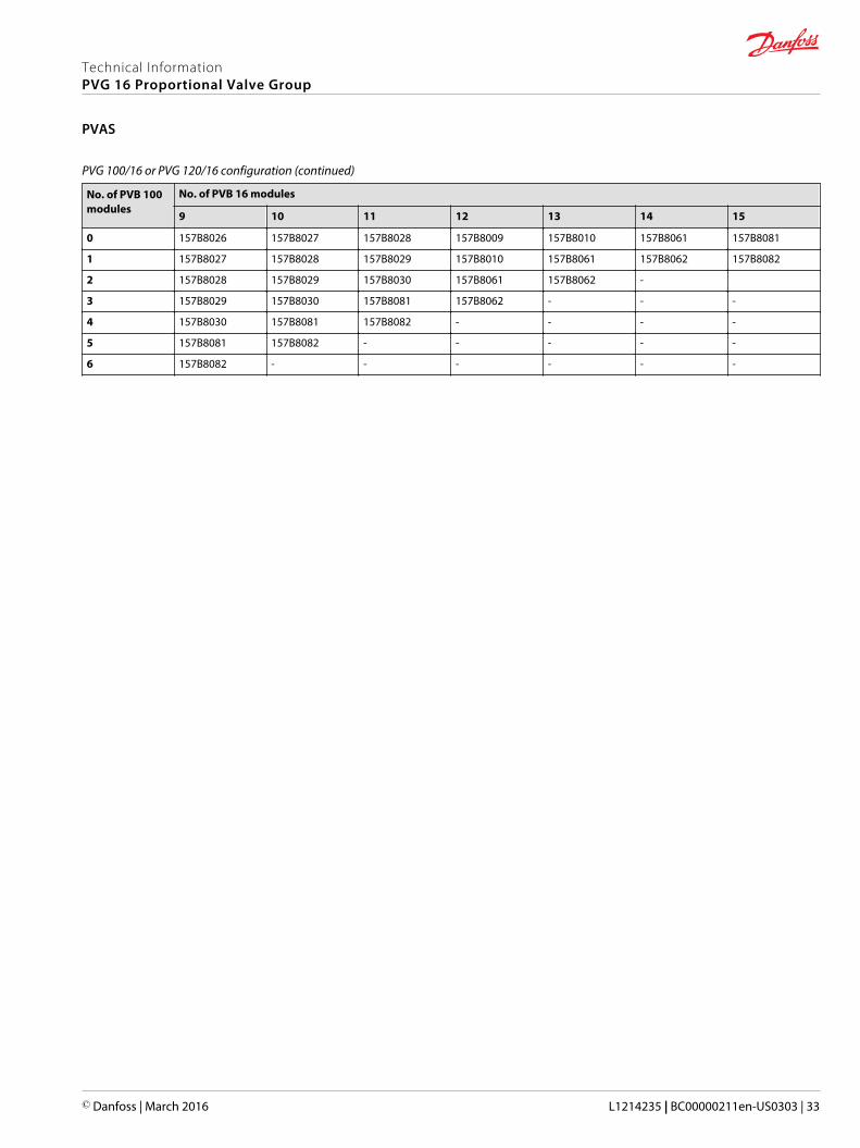
PVG 100/16 or PVG 120/16 configuration (continued)
No. of PVB 100modules
No. of PVB 16 modules
9 10 11 12 13 14 15
0 157B8026 157B8027 157B8028 157B8009 157B8010 157B8061 157B8081
1 157B8027 157B8028 157B8029 157B8010 157B8061 157B8062 157B8082
2 157B8028 157B8029 157B8030 157B8061 157B8062 -
3 157B8029 157B8030 157B8081 157B8062 - - -
4 157B8030 157B8081 157B8082 - - - -
5 157B8081 157B8082 - - - - -
6 157B8082 - - - - - -
Technical InformationPVG 16 Proportional Valve Group
PVAS
© Danfoss | March 2016 L1214235 | BC00000211en-US0303 | 33
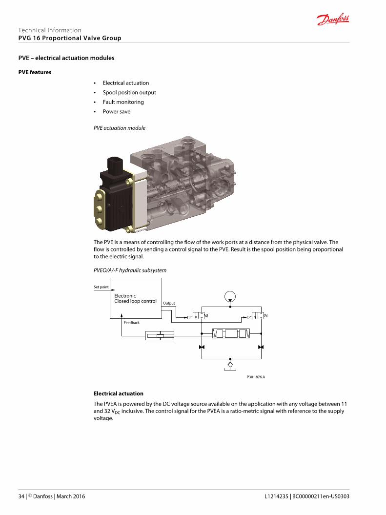
PVE features
• Electrical actuation
• Spool position output
• Fault monitoring
• Power save
PVE actuation module
The PVE is a means of controlling the flow of the work ports at a distance from the physical valve. Theflow is controlled by sending a control signal to the PVE. Result is the spool position being proportionalto the electric signal.
PVEO/A/-F hydraulic subsystem
P301 876.A
Set point
Output
Feedback
ElectronicClosed loop control
Electrical actuation
The PVEA is powered by the DC voltage source available on the application with any voltage between 11and 32 VDC inclusive. The control signal for the PVEA is a ratio-metric signal with reference to the supplyvoltage.
Technical InformationPVG 16 Proportional Valve Group
PVE – electrical actuation modules
34 | © Danfoss | March 2016 L1214235 | BC00000211en-US0303

Oil flow as a function of spool travel
1
1
6
6
Q
L/min [US gal/min]
1 2 3 4 5 1 2 3 4 5 6 7
PVE Us/UDC 25 [%] 50 [%] 75 [%]
SP VDC 3.75 2.50 1.25 0.50
PVM mm
10
20
30
40
50
60
70
[10]
[15]
[5]
[0.04] [0.08] [0.12] [0.16] [0.2] [0.04] [0.08] [0.12] [0.16] [0.2] [0.24] [0.28] [in]
[V]
AA
A
B
C
D
P005 598E.B
Giving the PVEA a control signal of 50% of supply voltage will make it place the spool in its neutralposition, hence no flow to the work ports. A signal (Us, UDC) between 25-50% or between 50-75% willmake the spool move in either direction. At 25 and 75% the spool will be at full stroke at either side.
The PVEA and PVEA-F features an integrated feedback transducer that measures spool movement inrelation to the input signal. This feedback is part of the closed loop control of the spool position makingthe PVEA and PVEA-F capable of compensating for changes in the flow forces on the spool, pilot pressureor the viscosity of the oil.
The PVEO is powered by a fixed voltage of either 12 or 24 VDC. Applying this voltage to one of two pinswill make the PVEO actuate the spool to full stroke. When removing the voltage again the spool willreturn to neutral position.
Spool position output
The PVEA has a build in spool monitoring circuit. This circuit is communicating to the surroundings by ananalogue 0-5 VDC pin. The translation between a voltage out on the pin to spool movement can be foundin the technical characteristics section of this chapter.
The voltage outputted between 1.25 to 2.5 VDC and 2.5 to 3.75 VDC is directly proportional to the positionof the spool and therefore the flow.
The PVEO has no spool position output pin.
Technical InformationPVG 16 Proportional Valve Group
PVE – electrical actuation modules
© Danfoss | March 2016 L1214235 | BC00000211en-US0303 | 35
Fault monitoring
When the voltage on the SP-pin goes to 5 VDC the PVEA has detected an error. The error detection ismonitoring the sanity of the command signal, comparing the spool position with the command signaland the closed loop control.
Besides outputting 5 VDC on the spool position pin the PVEA will change the color of the LED for visualrecognition of the error. Normally the LED would light green, but in case of a command signal error theLED will be flashing red. If any of the other two errors occur the LED will change its color to constant red.
The PVEO has no fault monitoring.
Power save
The PVEA has a power save mode. This mode is entered when the command signal to the PVEA is below15% of the supply voltage. Entering power save mode will turn off the power to the solenoid valves.Power save mode can be identified by the LED blinking green at 1 Hz.
The PVEO has no power save mode.
PVEO/A code numbers
PVEO/A versions and code numbers
Description Code number
PVEO, electrical actuation, ON/OFF control 12 VDC control signal 11106793
24 VDC control signal 11106794
PVEA, electrical actuation, proportional control 11103692
PVEA-F, electrical actuation, proportional control, with float in B-direction 11106795
PVE-CI code numbers
PVE-CI versions and code numbers
Description Code number
PVEO-CI J1939/ISObus 11124002
PVEA-CI 11121945
PVEO-CI CANopen 11149443
PVEA-CI 11149437
Refer to PVE-CI, Series 6, Technical Information L1505234 for further information.
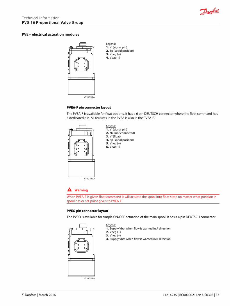
PVEA pin connector layout
The PVEA is available as the PVE for proportional control of the spool. It has a 4 pin DEUTSCH connector.
Technical InformationPVG 16 Proportional Valve Group
PVE – electrical actuation modules
36 | © Danfoss | March 2016 L1214235 | BC00000211en-US0303
1
23
4
V310 358.A
Legend:1. Vi (signal pin)2. Sp (spool position)3. Vneg (÷)4. Vbat (+)
PVEA-F pin connector layout
The PVEA-F is available for float options. It has a 6 pin DEUTSCH connector where the float command hasa dedicated pin. All features in the PVEA is also in the PVEA-F.
1234
56
V310 359.A
Legend:1. Vi (signal pin)2. NC (not connected)3. Vf (float)4. Sp (spool position)5. Vneg (÷)6. Vbat (+)
W Warning
When PVEA-F is given float command it will actuate the spool into float state no matter what position inspool has or set point given to PVEA-F.
PVEO pin connector layout
The PVEO is available for simple ON/OFF actuation of the main spool. It has a 4 pin DEUTSCH connector.
1
23
4
V310 358.A
Legend:1. Supply Vbat when flow is wanted in A direction2. Vneg (÷)3. Vneg (÷)4. Supply Vbat when flow is wanted in B-direction
Technical InformationPVG 16 Proportional Valve Group
PVE – electrical actuation modules
© Danfoss | March 2016 L1214235 | BC00000211en-US0303 | 37
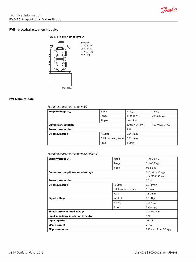
PVE-CI pin connector layout
1
23
4
12 3
4
P301 834.A
Legend:1. CAN_H2. CAN_L3. Vbat (+)4. Vneg (÷)
PVE technical data
Technical characteristics for PVEO
Supply voltage UDC Rated 12 VDC 24 VDC
Range 11 to 15 VDC 22 to 30 VDC
Ripple max. 5 %
Current consumption 320 mA @ 12 VDC 160 mA @ 24 VDC
Power consumption 4 W
Oil consumption Neutral 0.04 l/min
Full flow steady state 0.06 l/min
Peak 1 l/min
Technical characteristics for PVEA / PVEA-F
Supply voltage UDC Rated 11 to 32 VDC
Range 11 to 32 VDC
Ripple max. 5 %
Current consumption at rated voltage 320 mA @ 12 VDC170 mA @ 24 VDC
Power consumption 0.5 W
Oil consumption Neutral 0.04 l/min
Full flow steady state 1 l/min
Peak 1.3 l/min
Signal voltage Neutral 0.5 • UDC
A-port 0.25 • UDC
B-port 0.75 • UDC
Signal current at rated voltage 0.25 to 70 mA
Input impedance in relation to neutral 12 kΩ
Input capacitor 100 µF
SP pin current 2 mA
SP pin resolution 250 steps from 0-5 VDC
Technical InformationPVG 16 Proportional Valve Group
PVE – electrical actuation modules
38 | © Danfoss | March 2016 L1214235 | BC00000211en-US0303
Technical characteristics for PVE-CI
Supply voltage UDC Rated 11 to 32 VDC
Range 11 to 32 VDC
Ripple max. 5 %
Current consumption at rated voltage 320 mA @ 12 VDC170 mA @ 24 VDC
Power consumption 0.5 W
Oil consumption Neutral 0.04 l/min
Full flow steady state 1 l/min
Peak 1.3 l/min
Refer to PVE-CI, Series 6, Technical Information L1505234 for further information.
SP pin
Voltage Translation
0.5 VDC Float (B-direction)
1.25 VDC Full flow B-port
2.5 VDC Neutral
3.75 VDC Full flow A-port
5.0 VDC Error
PVEO/PVEO-CI reaction time
Reaction time A-direction B-direction
Neutral to full spool stroke 173 ms 105 ms
Full spool stroke to neutral 396 ms 565 ms
PVEA/PVEA-F/PVEA-CI reaction time
Reaction time A-direction B-direction
Neutral to full spool stroke 188 ms 142 ms
Full spool stroke to neutral 125 ms 120 ms
PVEO and PVEA/PVEA-F oil consumption
PVE type PVEO PVEA/PVEA-F
Neutral position 0.04 /min [0.01 US gal/min] 0.04 l/min [0.01 US gal/min]
Actuating to full stroke 0.6 l/min [0.16 US gal/min] 1 l/min [0.26 US gal/min]
Full stroke steady state 1 l/min [0.26 US gal/min] 1.3 l/min [0.34 US gal/min]
Technical InformationPVG 16 Proportional Valve Group
PVE – electrical actuation modules
© Danfoss | March 2016 L1214235 | BC00000211en-US0303 | 39

Fault monitoring overview
PVEType
Fault monitoring Delay before errorout
Error mode LED light
PVEO No fault monitoring – – –
PVEA Passive 250 ms No fault Green
Input signal faults Flashing red
Transducer (LVDT) Constant red
Close loop fault
PVE oil flow characteristics
The letters AA, A, B, C and D denotes the spool flow sizes ranging from 5 l/min to 65 l/min [from 1.32to17.17 US gal/min]. All tests are done by using Tellus32 @ 21mm2/s.
Oil flow as a function of spool travel
1
1
6
6
Q
L/min [US gal/min]
1 2 3 4 5 1 2 3 4 5 6 7
PVE Us/UDC 25 [%] 50 [%] 75 [%]
SP VDC 3.75 2.50 1.25 0.50
PVM mm
10
20
30
40
50
60
70
[10]
[15]
[5]
[0.04] [0.08] [0.12] [0.16] [0.2] [0.04] [0.08] [0.12] [0.16] [0.2] [0.24] [0.28] [in]
[V]
AA
A
B
C
D
P005 598E.B
Technical InformationPVG 16 Proportional Valve Group
PVE – electrical actuation modules
40 | © Danfoss | March 2016 L1214235 | BC00000211en-US0303

PVEO and PVEO-CI voltage-position diagram PVEA/PVEA-F and PVEA-CI voltage-position diagram
P005 610.B
PVEO
Y
X
3%
P005 609.B
PVEA
Y
X
PVHC, high current actuation module – electrical
• Electrical actuation
• Pin layout
PVHC high current actuator
The PVHC is a means of controlling the flow of the work ports at a distance from the physical valve. Theflow is controlled by sending a PWM signal to the one of two pressure reduction valves. Result is thespool position being proportional to the current.
Technical InformationPVG 16 Proportional Valve Group
PVE – electrical actuation modules
© Danfoss | March 2016 L1214235 | BC00000211en-US0303 | 41
PVHC hydraulic subsystem
+-
Setpoint
Driver A
CurrentFeedback A
Driver B
CurrentFeedback B
+-
-
-
V310 434
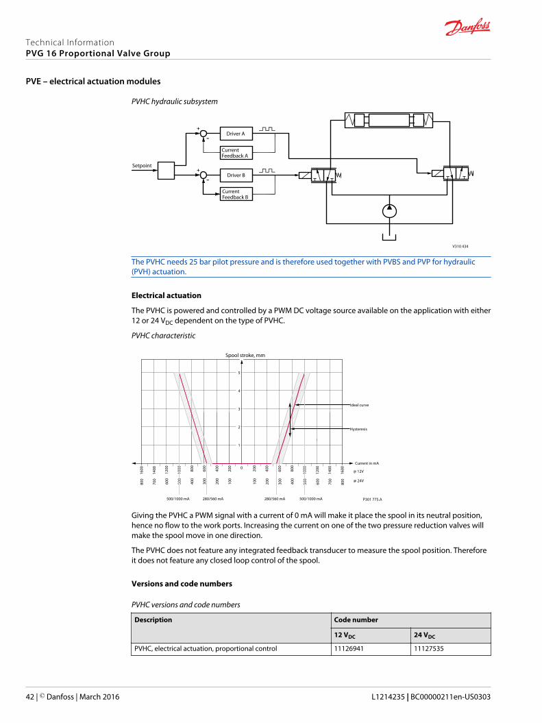
The PVHC needs 25 bar pilot pressure and is therefore used together with PVBS and PVP for hydraulic(PVH) actuation.
Electrical actuation
The PVHC is powered and controlled by a PWM DC voltage source available on the application with either12 or 24 VDC dependent on the type of PVHC.
PVHC characteristic
0
400
200
600
120080
0
1000
1400
Current in mA
Spool stroke, mm
5
4
3
2
1
160040
0
200
600
1200 80
0
1000
1400
1600
200
100
300
600
400
500
700
800
200
100
300
600
400
500
700
800
@ 12V
@ 24V
P301 775.A
Ideal curve
Hysteresis
280/560 mA 500/1000 mA280/560 mA500/1000 mA
Giving the PVHC a PWM signal with a current of 0 mA will make it place the spool in its neutral position,hence no flow to the work ports. Increasing the current on one of the two pressure reduction valves willmake the spool move in one direction.
The PVHC does not feature any integrated feedback transducer to measure the spool position. Thereforeit does not feature any closed loop control of the spool.
Versions and code numbers
PVHC versions and code numbers
Description Code number
12 VDC 24 VDC
PVHC, electrical actuation, proportional control 11126941 11127535
Technical InformationPVG 16 Proportional Valve Group
PVE – electrical actuation modules
42 | © Danfoss | March 2016 L1214235 | BC00000211en-US0303

PVHC pin layout – DEUTSCH version
V310 435
Technical characteristics for PVHC
PVHC technical characteristics
Supply voltage UDC 12 VDC 24 VDC
Controller output current 0 – 1200 mA 0 – 600 mA
Resistance 4.75 Ω +-5% 20.8 Ω +-5%
Pilot pressure control range 20 – 25 bar [290 – 363 psi]
Recommended dither frequency 40 Hz
Recommended amplitude 250 mA
PVHC reaction time
From neutral position to max. spool travel at power on A-direction <90 ms
B-direction <90 ms
From max. spool travel to neutral position at power off A-direction <90 ms
B-direction <90 ms
Technical InformationPVG 16 Proportional Valve Group
PVE – electrical actuation modules
© Danfoss | March 2016 L1214235 | BC00000211en-US0303 | 43
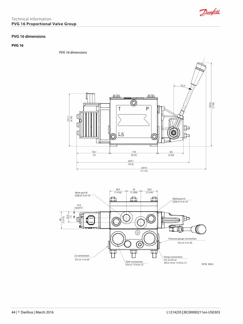
PVG 16
PVG 16 dimensions
22.5°
V310 356.CTank connection:G¾ or 11⁄16 in-12
Pump connection:G½ or G¾ or 7⁄8 in-14 or 11⁄16 in-12
Work port A:G3⁄8 or ¾ in-16
Work port B:G3⁄8 or ¾ in-16
38.5[1.516]
40[1
.575
]
121.
7[4
.79]
192.
6[7
.58]
25.5
[1]
14.5[0.571]
33[1.299]
38.5[1.516]
297.9[11.73]
259.1[10.2]
110[4.33]
60[2.36]
76.1[3]
LS connection:
G¼ or ½ in-20
G¼ or ½ in-20
Pressure gauge connection:
Technical InformationPVG 16 Proportional Valve Group
PVG 16 dimensions
44 | © Danfoss | March 2016 L1214235 | BC00000211en-US0303
270.5 [10.65]
V310 446
283.5 [11.16]
100.4 [3.95]
99.5
[3.9
2]
L2L1
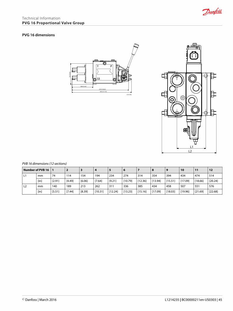
PVB 16 dimensions (12 sections)
Number of PVB 16 1 2 3 4 5 6 7 8 9 10 11 12
L1 mm 74 114 154 194 234 274 314 354 394 434 474 514
[in] [2.91] [4.49] [6.06] [7.64] [9.21] [10.79] [12.36] [13.94] [15.51] [17.09] [18.66] [20.24]
L2 mm 140 189 213 262 311 336 385 434 458 507 551 576
[in] [5.51] [7.44] [8.39] [10.31] [12.24] [13.23] [15.16] [17.09] [18.03] [19.96] [21.69] [22.68]
Technical InformationPVG 16 Proportional Valve Group
PVG 16 dimensions
© Danfoss | March 2016 L1214235 | BC00000211en-US0303 | 45
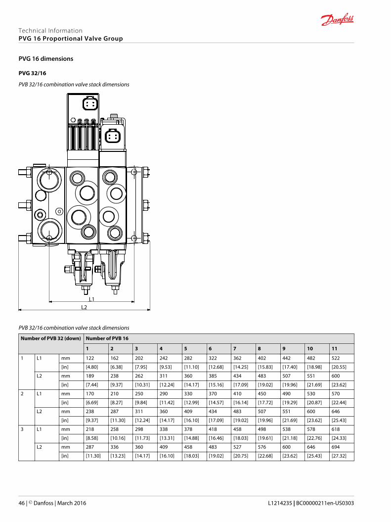
PVG 32/16
PVB 32/16 combination valve stack dimensions
L1L2
PVB 32/16 combination valve stack dimensions
Number of PVB 32 (down) Number of PVB 16
1 2 3 4 5 6 7 8 9 10 11
1 L1 mm 122 162 202 242 282 322 362 402 442 482 522
[in] [4.80] [6.38] [7.95] [9.53] [11.10] [12.68] [14.25] [15.83] [17.40] [18.98] [20.55]
L2 mm 189 238 262 311 360 385 434 483 507 551 600
[in] [7.44] [9.37] [10.31] [12.24] [14.17] [15.16] [17.09] [19.02] [19.96] [21.69] [23.62]
2 L1 mm 170 210 250 290 330 370 410 450 490 530 570
[in] [6.69] [8.27] [9.84] [11.42] [12.99] [14.57] [16.14] [17.72] [19.29] [20.87] [22.44]
L2 mm 238 287 311 360 409 434 483 507 551 600 646
[in] [9.37] [11.30] [12.24] [14.17] [16.10] [17.09] [19.02] [19.96] [21.69] [23.62] [25.43]
3 L1 mm 218 258 298 338 378 418 458 498 538 578 618
[in] [8.58] [10.16] [11.73] [13.31] [14.88] [16.46] [18.03] [19.61] [21.18] [22.76] [24.33]
L2 mm 287 336 360 409 458 483 527 576 600 646 694
[in] [11.30] [13.23] [14.17] [16.10] [18.03] [19.02] [20.75] [22.68] [23.62] [25.43] [27.32]
Technical InformationPVG 16 Proportional Valve Group
PVG 16 dimensions
46 | © Danfoss | March 2016 L1214235 | BC00000211en-US0303
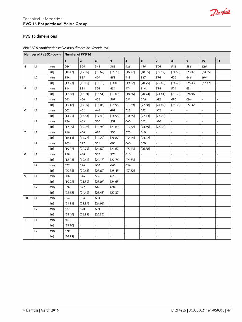
PVB 32/16 combination valve stack dimensions (continued)
Number of PVB 32 (down) Number of PVB 16
1 2 3 4 5 6 7 8 9 10 11
4 L1 mm 266 306 346 386 426 466 506 546 586 626 -
[in] [10.47] [12.05] [13.62] [15.20] [16.77] [18.35] [19.92] [21.50] [23.07] [24.65] -
L2 mm 336 385 409 458 483 527 576 622 646 694 -
[in] [13.23] [15.16] [16.10] [18.03] [19.02] [20.75] [22.68] [24.49] [25.43] [27.32] -
5 L1 mm 314 354 394 434 474 514 554 594 634 - -
[in] [12.36] [13.94] [15.51] [17.09] [18.66] [20.24] [21.81] [23.39] [24.96] - -
L2 mm 385 434 458 507 551 576 622 670 694 - -
[in] [15.16] [17.09] [18.03] [19.96] [21.69] [22.68] [24.49] [26.38] [27.32] - -
6 L1 mm 362 402 442 482 522 562 602 - - - -
[in] [14.25] [15.83] [17.40] [18.98] [20.55] [22.13] [23.70] - - - -
L2 mm 434 483 507 551 600 622 670 - - - -
[in] [17.09] [19.02] [19.96] [21.69] [23.62] [24.49] [26.38] - - - -
7 L1 mm 410 450 490 530 570 610 - - - - -
[in] [16.14] [17.72] [19.29] [20.87] [22.44] [24.02] - - - - -
L2 mm 483 527 551 600 646 670 - - - - -
[in] [19.02] [20.75] [21.69] [23.62] [25.43] [26.38] - - - - -
8 L1 mm 458 498 538 578 618 - - - - - -
[in] [18.03] [19.61] [21.18] [22.76] [24.33] - - - - - -
L2 mm 527 576 600 646 694 - - - - - -
[in] [20.75] [22.68] [23.62] [25.43] [27.32] - - - - - -
9 L1 mm 506 546 586 626 - - - - - - -
[in] [19.92] [21.50] [23.07] [24.65] - - - - - - -
L2 mm 576 622 646 694 - - - - - - -
[in] [22.68] [24.49] [25.43] [27.32] - - - - - - -
10 L1 mm 554 594 634 - - - - - - - -
[in] [21.81] [23.39] [24.96] - - - - - - - -
L2 mm 622 670 694 - - - - - - - -
[in] [24.49] [26.38] [27.32] - - - - - - - -
11 L1 mm 602 - - - - - - - - - -
[in] [23.70] - - - - - - - - - -
L2 mm 670 - - - - - - - - - -
[in] [26.38] - - - - - - - - - -
Technical InformationPVG 16 Proportional Valve Group
PVG 16 dimensions
© Danfoss | March 2016 L1214235 | BC00000211en-US0303 | 47
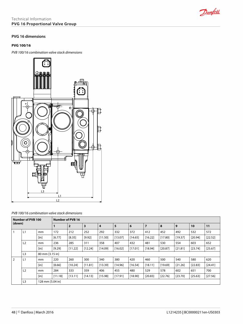
PVG 100/16
PVB 100/16 combination valve stack dimensions
L1L2
L3
PVB 100/16 combination valve stack dimensions
Number of PVB 100(down)
Number of PVB 16
1 2 3 4 5 6 7 8 9 10 11
1 L1 mm 172 212 252 292 332 372 412 452 492 532 572
[in] [6.77] [8.35] [9.92] [11.50] [13.07] [14.65] [16.22] [17.80] [19.37] [20.94] [22.52]
L2 mm 236 285 311 358 407 432 481 530 554 603 652
[in] [9.29] [11.22] [12.24] [14.09] [16.02] [17.01] [18.94] [20.87] [21.81] [23.74] [25.67]
L3 80 mm [3.15 in]
2 L1 mm 220 260 300 340 380 420 460 500 540 580 620
[in] [8.66] [10.24] [11.81] [13.39] [14.96] [16.54] [18.11] [19.69] [21.26] [22.83] [24.41]
L2 mm 284 333 359 406 455 480 529 578 602 651 700
[in] [11.18] [13.11] [14.13] [15.98] [17.91] [18.90] [20.83] [22.76] [23.70] [25.63] [27.56]
L3 128 mm [5.04 in]
Technical InformationPVG 16 Proportional Valve Group
PVG 16 dimensions
48 | © Danfoss | March 2016 L1214235 | BC00000211en-US0303
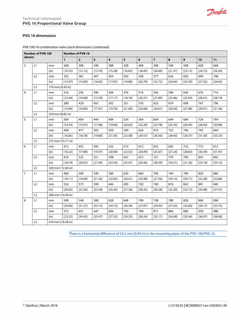
PVB 100/16 combination valve stack dimensions (continued)
Number of PVB 100(down)
Number of PVB 16
1 2 3 4 5 6 7 8 9 10 11
3 L1 mm 268 308 348 388 428 468 508 548 588 628 668
[in] [10.55] [12.13] [13.70] [15.28] [16.85] [18.43] [20.00] [21.57] [23.15] [24.72] [26.30]
L2 mm 332 381 407 454 503 528 577 626 650 699 748
[in] [13.07] [15.00] [16.02] [17.87] [19.80] [20.79] [22.72] [24.65] [25.59] [27.52] [29.45]
L3 176 mm [6.93 in]
4 L1 mm 316 256 396 436 476 516 556 596 636 676 716
[in] [12.44] [10.08] [15.59] [17.17] [18.74] [20.31] [21.89] [23.46] [25.04] [26.61] [28.19]
L2 mm 380 429 455 502 551 576 625 674 698 747 796
[in] [14.96] [16.89] [17.91] [19.76] [21.69] [22.68] [24.61] [26.54] [27.48] [29.41] [31.34]
L3 224 mm [8.82 in]
5 L1 mm 364 404 444 484 524 564 604 644 684 724 764
[in] [14.33] [15.91] [17.48] [19.06] [20.63] [22.20] [23.78] [25.35] [26.93] [28.50] [30.08]
L2 mm 428 477 503 550 599 624 673 722 746 795 844
[in] [16.85] [18.78] [19.80] [21.65] [23.58] [24.57] [26.50] [28.43] [29.37] [31.30] [33.23]
L3 272 mm [10.71 in]
6 L1 mm 412 452 492 532 572 612 652 692 732 772 812
[in] [16.22] [17.80] [19.37] [20.94] [22.52] [24.09] [25.67] [27.24] [28.82] [30.39] [31.97]
L2 mm 476 525 551 598 647 672 721 770 794 843 892
[in] [18.74] [20.67] [21.69] [23.54] [25.47] [26.46] [28.39] [30.31] [31.26] [33.19] [35.12]
L3 320 mm [12.60 in]
7 L1 mm 460 500 540 580 620 660 700 740 780 820 860
[in] [18.11] [19.69] [21.26] [22.83] [24.41] [25.98] [27.56] [29.13] [30.71] [32.28] [33.86]
L2 mm 524 573 599 646 695 720 769 818 842 891 940
[in] [20.63] [22.56] [23.58] [25.43] [27.36] [28.35] [30.28] [32.20] [33.15] [35.08] [37.01]
L3 368 mm [14.49 in]
8 L1 mm 508 548 588 628 668 708 748 788 828 868 908
[in] [20.00] [21.57] [23.15] [24.72] [26.30] [27.87] [29.45] [31.02] [32.60] [34.17] [35.75]
L2 mm 572 621 647 694 743 768 817 866 890 939 988
[in] [22.52] [24.45] [25.47] [27.32] [29.25] [30.24] [32.17] [34.09] [35.04] [36.97] [38.90]
L3 416 mm [16.38 in]
There is a horizontal difference of 23.5 mm [0.93 in] in the mounting plane of the PVG 100/PVG 16.
Technical InformationPVG 16 Proportional Valve Group
PVG 16 dimensions
© Danfoss | March 2016 L1214235 | BC00000211en-US0303 | 49
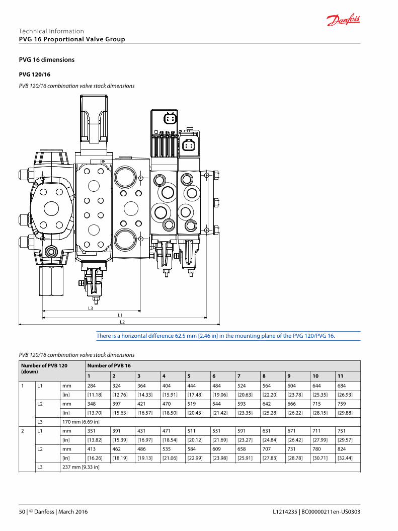
PVG 120/16
PVB 120/16 combination valve stack dimensions
L1L2
L3
There is a horizontal difference 62.5 mm [2.46 in] in the mounting plane of the PVG 120/PVG 16.
PVB 120/16 combination valve stack dimensions
Number of PVB 120(down)
Number of PVB 16
1 2 3 4 5 6 7 8 9 10 11
1 L1 mm 284 324 364 404 444 484 524 564 604 644 684
[in] [11.18] [12.76] [14.33] [15.91] [17.48] [19.06] [20.63] [22.20] [23.78] [25.35] [26.93]
L2 mm 348 397 421 470 519 544 593 642 666 715 759
[in] [13.70] [15.63] [16.57] [18.50] [20.43] [21.42] [23.35] [25.28] [26.22] [28.15] [29.88]
L3 170 mm [6.69 in]
2 L1 mm 351 391 431 471 511 551 591 631 671 711 751
[in] [13.82] [15.39] [16.97] [18.54] [20.12] [21.69] [23.27] [24.84] [26.42] [27.99] [29.57]
L2 mm 413 462 486 535 584 609 658 707 731 780 824
[in] [16.26] [18.19] [19.13] [21.06] [22.99] [23.98] [25.91] [27.83] [28.78] [30.71] [32.44]
L3 237 mm [9.33 in]
Technical InformationPVG 16 Proportional Valve Group
PVG 16 dimensions
50 | © Danfoss | March 2016 L1214235 | BC00000211en-US0303

PVB 120/16 combination valve stack dimensions (continued)
Number of PVB 120(down)
Number of PVB 16
1 2 3 4 5 6 7 8 9 10 11
3 L1 mm 418 458 498 538 578 618 658 698 738 778 818
[in] [16.46] [18.03] [19.61] [21.18] [22.76] [24.33] [25.91] [27.48] [29.06] [30.63] [32.20]
L2 mm 478 527 551 600 649 674 723 772 796 845 889
[in] [18.82] [20.75] [21.69] [23.62] [25.55] [26.54] [28.46] [30.39] [31.34] [33.27] [35.00]
L3 304 mm [11.91 in]
4 L1 mm 485 525 565 605 545 685 725 765 805 845 885
[in] [19.09] [20.67] [22.24] [23.82] [21.46] [26.97] [28.54] [30.12] [31.69] [33.27] [34.84]
L2 mm 543 592 616 665 714 739 788 837 86 910 954
[in] [21.38] [23.31] [24.25] [26.18] [28.11] [29.09] [31.02] [32.95] [3.39] [35.83] [37.56]
L3 371 mm [14.61 in]
5 L1 mm 552 592 632 672 712 752 792 832 872 912 952
[in] [21.73] [23.31] [24.8] [26.46] [28.03] [29.61] [31.18] [32.76] [34.33] [35.91] [37.48]
L2 mm 608 657 681 730 779 804 853 902 926 975 1019
[in] [23.94] [25.87] [26.81] [28.74] [30.67] [31.65] [33.58] [35.51] [36.46] [38.39] [40.12]
L3 438 mm [17.24 in]
6 L1 mm 619 659 699 739 779 819 859 899 939 979 1019
[in] [24.37] [25.94] [27.52] [29.09] [30.67] [32.24] [33.82] [35.39] [36.97] [38.54] [40.12]
L2 mm 673 722 746 795 844 869 918 967 991 1040 1084
[in] [26.50] [28.43] [29.37] [31.30] [33.23] [34.21] [36.14] [38.07] [39.02] [40.94] [42.68]
L3 505 mm [19.88 in]
7 L1 mm 686 726 766 806 846 886 926 966 1006 1046 1086
[in] [27.01] [28.58] [30.16] [31.73] [33.31] [34.88] [36.46] [38.03] [39.61] [41.18] [42.76]
L2 mm 738 787 811 860 909 934 983 1032 1056 1105 1149
[in] [29.06] [30.98] [31.93] [33.86] [35.79] [36.77] [38.70] [40.63] [41.57] [43.50] [45.24]
L3 572 mm [22.52 in]
8 L1 mm 753 793 833 873 913 953 993 1033 1073 1113 1153
[in] [29.65] [31.22] [32.80] [34.37] [35.94] [37.52] [39.09] [40.67] [42.24] [43.82] [45.39]
L2 mm 803 852 876 925 974 999 1048 1097 1121 1170 1214
[in] [31.61] [33.54] [34.49] [36.42] [38.35] [39.33] [41.26] [43.19] [44.13] [46.06] [47.80]
L3 639 mm [25.16 in]
Due to the large size of the PVG 120 interface-module it is necessary to have at least one PVG 32 modulebetween the PVGI and the first PVG 16 slice.
Technical InformationPVG 16 Proportional Valve Group
PVG 16 dimensions
© Danfoss | March 2016 L1214235 | BC00000211en-US0303 | 51
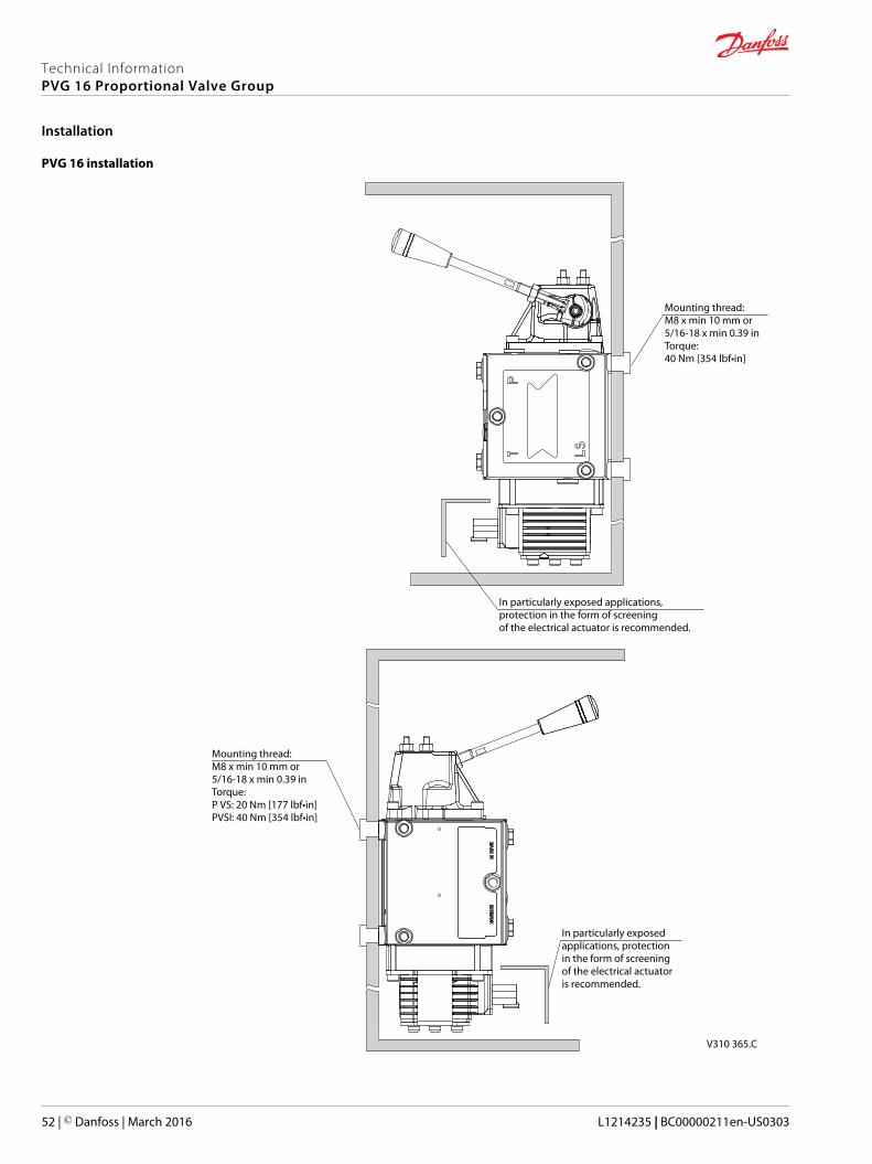
PVG 16 installation
In particularly exposed applications, protection in the form of screening of the electrical actuator is recommended.
In particularly exposed applications, protection in the form of screening of the electrical actuator is recommended.
Mounting thread: M8 x min 10 mm or5/16-18 x min 0.39 inTorque: P VS: 20 Nm [177 lbf•in]PVSI: 40 Nm [354 lbf•in]
Mounting thread: M8 x min 10 mm or5/16-18 x min 0.39 inTorque: 40 Nm [354 lbf•in]
V310 365.C
Technical InformationPVG 16 Proportional Valve Group
Installation
52 | © Danfoss | March 2016 L1214235 | BC00000211en-US0303
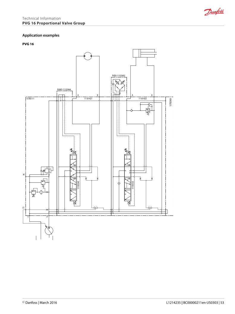
PVG 16
LS
T P
M
157B5111A
11101421B A
11101425B
157B
2000
250
1110
5535
PVEA-1110369211
1055
40
PVMD-11102464
Technical InformationPVG 16 Proportional Valve Group
Application examples
© Danfoss | March 2016 L1214235 | BC00000211en-US0303 | 53
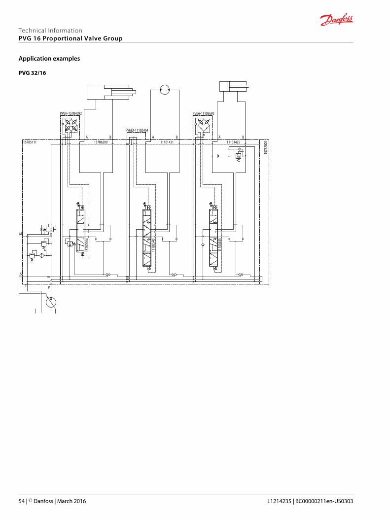
PVG 32/16
LS
T P
M
157B5111A
11101421B A
11101425B
157B
2000
250
1110
5535
PVEA-11103692
1110
5540
PVMD-11102464
A157B6200
B
157B
7004
PVEH-157B4092
Technical InformationPVG 16 Proportional Valve Group
Application examples
54 | © Danfoss | March 2016 L1214235 | BC00000211en-US0303

PVG 100/16
T0 Pg P Pp
LS
161B5111 161B6250A B
161B
7026
161B2200
T
350
A11101421
B A11101425
B
157B
2000
250
1110
5535
PVEA-11103692
1110
5540
PVMD-11102464
PVEH-157B4092
PVG 120/16
LS
P
MA
155G5038A
155G6016B T
155G7032
Pp
155G7042
A157B6000
B
157B
7004
PVEH-157B4092PVEO-155G4272
155G
6468
A11101421
B A11101425
B
157B
2000
250
1110
5535
PVEA-11103692
1110
5540
PVMD-11102464
Technical InformationPVG 16 Proportional Valve Group
Application examples
© Danfoss | March 2016 L1214235 | BC00000211en-US0303 | 55
Due to the large size of the PVG 120 interface-module it is necessary to have at least one PVG 32 modulebetween the PVGI and the first PVG 16 slice.
Technical InformationPVG 16 Proportional Valve Group
Application examples
56 | © Danfoss | March 2016 L1214235 | BC00000211en-US0303
Hydraulic system efficiency
A complete hydraulic system can be implemented in many different ways. There is no sole answer to:which system solution is the right one? The solution will depend on what is the aim of the vehiclemanufacturers, if they are aiming for high productivity, and/or a low fuel consumption, and/or a compactdesign, and/or a high operator comfort, etc.
An important topic to consider when it comes to system design is energy efficiency.Components in asystem have their individual efficiency and as such the components contribute to the total energyconsumption. This energy consumption is directly proportional with the emission of the application andthe operating costs.
The power needed to generate the flow and pressure for each system function is vital as surplus energyused to generate excess flow and pressure is converted into heat and thereby loss.
There are generally three types of mobile hydraulic systems:• Fixed displacement with constant flow,
• Variable displacement with constant pressure and
• Variable displacement with load sense (LS).
Fixed displacement system with constant flow
Uses a pump with fixed displacement to generate a fixed flow to the system. In standby the flow is sendfrom the pump through the valve and back into the reservoir. Whenever a consumer requests a portionof the flow to perform a work function, the fixed displacement system brings the entire flow up to theload pressure. The valve will then divide the flow into work port flow and surplus flow sending this backto the reservoir.
The efficiency of a fixed displacement system is directly proportional to the percentage of the total flowused by the consumer. If the consumer uses 10% of the total flow available the fixed displacementsystem is 10% efficient. If the consumer uses 75% of the total available flow the system is 75% efficient.
Variable displacement system with constant pressure
Uses a variable displacement pump to regulate the flow to system consumer needs. The flow is alwayspressurized to the setting of the pump pressure compensator independent of the consumer(s) pressureneed. In standby the pressure remains at full system pressure and only leakage flow is circulated back tothe reservoir. Whenever a consumer request a flow to perform a work function the pump will deliver thisflow only, but at full system pressure, independent of the function pressure need.
The efficiency of a fixed displacement system is directly proportional to the percentage of the totalpressure needed to perform the work, If 10% of the pressure is needed the fixed displacement system is10% efficient. If 75% of the pressure is needed the fixed displacement system is 75% efficient.
Variable displacement system with load sense
Uses a variable displacement pump to give the consumer the requested flow at the needed pressure. Instandby only pump leakage is circulated back to reservoir – at only margin pressure. Whenever aconsumer requests a flow the pump delivers this flow at needed pressure plus a margin pressure tocompensate internal resistance and system control.
The efficiency of a LS system, despite its pressure control, is not proportional to the flow or pressure but aresult of the pump margin pressure setting.
The easiest way to compare the efficiencies of the systems is to make an example. Considering a pumpwith a maximum flow rate of 200 l/min [52.8 US gal/min] and a system pressure of 300 bar [4351 psi].
A comparison of fixed and variable displacement systems gives the LS system a huge efficiencyadvantage over the fixed displacement system, especially in the high pressure and low-to-medium flowapplications.
Technical InformationPVG 16 Proportional Valve Group
Hydraulic system
© Danfoss | March 2016 L1214235 | BC00000211en-US0303 | 57

Fixed vs variable displacement system
100
80
60
40
20
00 50 100 150 200
Flow (l/min)
LS@25 bar
Constant flow
LS@75 bar
LS@150 barLS@300 bar
P005 913
%
Considering multiple consumers where the high flow work functions are seldom used, the LS system willincrease the advantage over the fixed displacement system.
A comparison of fixed and variable displacement systems gives the variable displacement system anefficiency advantage over the fixed displacement system in the lower pressure range of an application.
Fixed vs variable displacement system
100
80
60
40
20
00 50 100 150 200 250 300
Pressure (bar)
Constant pressure
Load sense
P005 914
%
Considering multiple consumers at different pressures the variable displacement system will increase theefficiency over the fixed displacement system.
Although the variable displacement system is the most complex of the three systems it potentially offersgreat advantages in terms of efficient use of energy and in turn the compliance with power managementrequirements. The PVG family offers products for both constant flow and load sense systems for the bestsolution for the mobile hydraulic system.
Technical InformationPVG 16 Proportional Valve Group
Hydraulic system
58 | © Danfoss | March 2016 L1214235 | BC00000211en-US0303
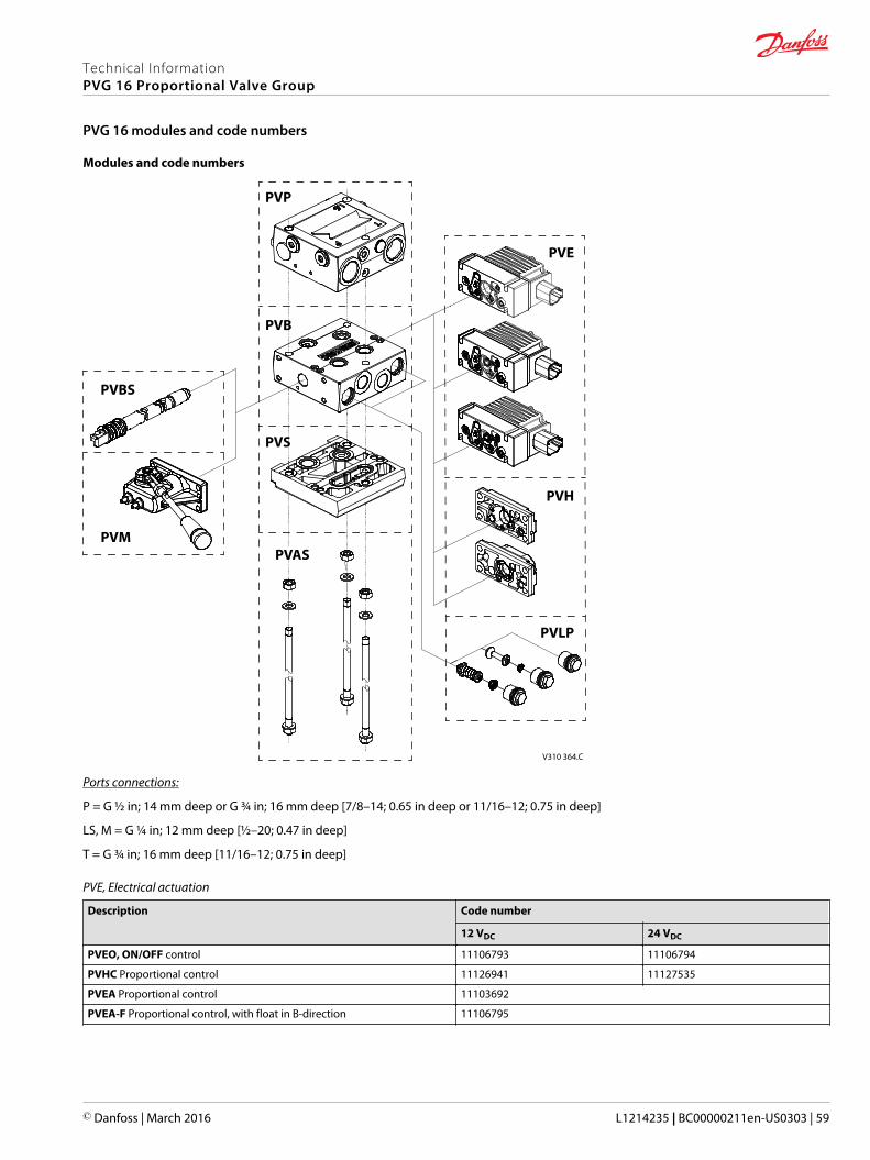
Modules and code numbers
V310 364.C
PVP
PVE
PVH
PVLP
PVAS
PVS
PVB
PVBS
PVM
Ports connections:
P = G ½ in; 14 mm deep or G ¾ in; 16 mm deep [7/8–14; 0.65 in deep or 11/16–12; 0.75 in deep]
LS, M = G ¼ in; 12 mm deep [½–20; 0.47 in deep]
T = G ¾ in; 16 mm deep [11/16–12; 0.75 in deep]
PVE, Electrical actuation
Description Code number
12 VDC 24 VDC
PVEO, ON/OFF control 11106793 11106794
PVHC Proportional control 11126941 11127535
PVEA Proportional control 11103692
PVEA-F Proportional control, with float in B-direction 11106795
Technical InformationPVG 16 Proportional Valve Group
PVG 16 modules and code numbers
© Danfoss | March 2016 L1214235 | BC00000211en-US0303 | 59
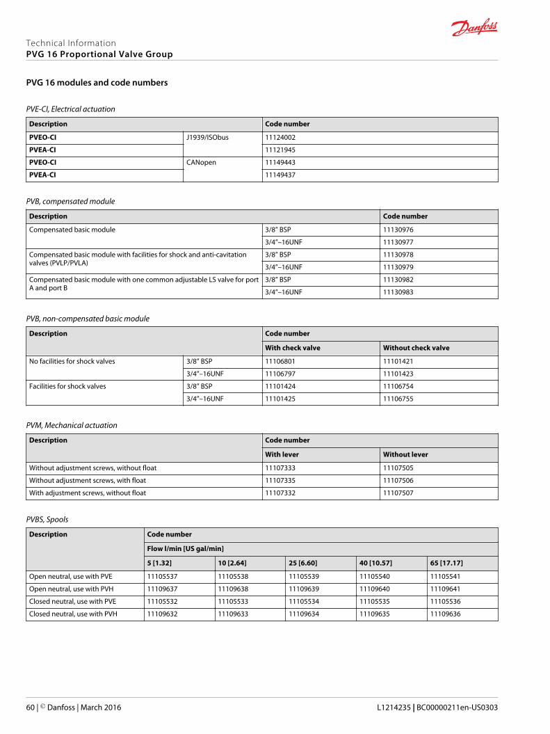
PVE-CI, Electrical actuation
Description Code number
PVEO-CI J1939/ISObus 11124002
PVEA-CI 11121945
PVEO-CI CANopen 11149443
PVEA-CI 11149437
PVB, compensated module
Description Code number
Compensated basic module 3/8” BSP 11130976
3/4”–16UNF 11130977
Compensated basic module with facilities for shock and anti-cavitationvalves (PVLP/PVLA)
3/8” BSP 11130978
3/4”–16UNF 11130979
Compensated basic module with one common adjustable LS valve for portA and port B
3/8” BSP 11130982
3/4”–16UNF 11130983
PVB, non-compensated basic module
Description Code number
With check valve Without check valve
No facilities for shock valves 3/8” BSP 11106801 11101421
3/4”–16UNF 11106797 11101423
Facilities for shock valves 3/8” BSP 11101424 11106754
3/4”–16UNF 11101425 11106755
PVM, Mechanical actuation
Description Code number
With lever Without lever
Without adjustment screws, without float 11107333 11107505
Without adjustment screws, with float 11107335 11107506
With adjustment screws, without float 11107332 11107507
PVBS, Spools
Description Code number
Flow l/min [US gal/min]
5 [1.32] 10 [2.64] 25 [6.60] 40 [10.57] 65 [17.17]
Open neutral, use with PVE 11105537 11105538 11105539 11105540 11105541
Open neutral, use with PVH 11109637 11109638 11109639 11109640 11109641
Closed neutral, use with PVE 11105532 11105533 11105534 11105535 11105536
Closed neutral, use with PVH 11109632 11109633 11109634 11109635 11109636
Technical InformationPVG 16 Proportional Valve Group
PVG 16 modules and code numbers
60 | © Danfoss | March 2016 L1214235 | BC00000211en-US0303
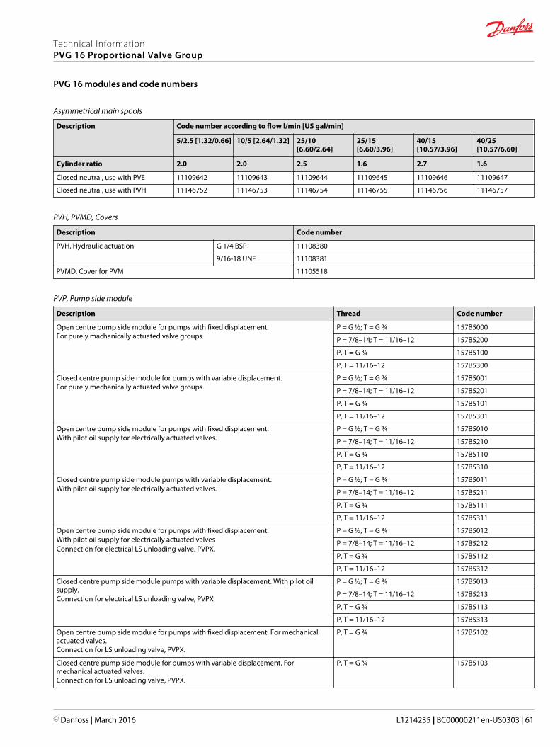
Asymmetrical main spools
Description Code number according to flow l/min [US gal/min]
5/2.5 [1.32/0.66] 10/5 [2.64/1.32] 25/10[6.60/2.64]
25/15[6.60/3.96]
40/15[10.57/3.96]
40/25[10.57/6.60]
Cylinder ratio 2.0 2.0 2.5 1.6 2.7 1.6
Closed neutral, use with PVE 11109642 11109643 11109644 11109645 11109646 11109647
Closed neutral, use with PVH 11146752 11146753 11146754 11146755 11146756 11146757
PVH, PVMD, Covers
Description Code number
PVH, Hydraulic actuation G 1/4 BSP 11108380
9/16-18 UNF 11108381
PVMD, Cover for PVM 11105518
PVP, Pump side module
Description Thread Code number
Open centre pump side module for pumps with fixed displacement.For purely machanically actuated valve groups.
P = G ½; T = G ¾ 157B5000
P = 7/8–14; T = 11/16–12 157B5200
P, T = G ¾ 157B5100
P, T = 11/16–12 157B5300
Closed centre pump side module for pumps with variable displacement.For purely mechanically actuated valve groups.
P = G ½; T = G ¾ 157B5001
P = 7/8–14; T = 11/16–12 157B5201
P, T = G ¾ 157B5101
P, T = 11/16–12 157B5301
Open centre pump side module for pumps with fixed displacement.With pilot oil supply for electrically actuated valves.
P = G ½; T = G ¾ 157B5010
P = 7/8–14; T = 11/16–12 157B5210
P, T = G ¾ 157B5110
P, T = 11/16–12 157B5310
Closed centre pump side module pumps with variable displacement.With pilot oil supply for electrically actuated valves.
P = G ½; T = G ¾ 157B5011
P = 7/8–14; T = 11/16–12 157B5211
P, T = G ¾ 157B5111
P, T = 11/16–12 157B5311
Open centre pump side module for pumps with fixed displacement.With pilot oil supply for electrically actuated valvesConnection for electrical LS unloading valve, PVPX.
P = G ½; T = G ¾ 157B5012
P = 7/8–14; T = 11/16–12 157B5212
P, T = G ¾ 157B5112
P, T = 11/16–12 157B5312
Closed centre pump side module pumps with variable displacement. With pilot oilsupply.Connection for electrical LS unloading valve, PVPX
P = G ½; T = G ¾ 157B5013
P = 7/8–14; T = 11/16–12 157B5213
P, T = G ¾ 157B5113
P, T = 11/16–12 157B5313
Open centre pump side module for pumps with fixed displacement. For mechanicalactuated valves.Connection for LS unloading valve, PVPX.
P, T = G ¾ 157B5102
Closed centre pump side module for pumps with variable displacement. Formechanical actuated valves.Connection for LS unloading valve, PVPX.
P, T = G ¾ 157B5103
Technical InformationPVG 16 Proportional Valve Group
PVG 16 modules and code numbers
© Danfoss | March 2016 L1214235 | BC00000211en-US0303 | 61

PVP, Pump side module (continued)
Description Thread Code number
Open centre pump side module for pumps with fixed displacement. With pilot oilsupply for electrical actuation and connection for pilot oil pressure.
P, T = G ¾ 157B5180
P, T = 11/16–12 157B5380
Closed centre pump side module pumps with variable displacement. With pilot oilsupply for electrical actuation and connection for pilot oil pressure.
P, T = G ¾ 157B5181
P, T = 11/16–12 157B5381
Open centre pump side module for pumps with fixed displacement. With pilot oilsupply for hydraulic actuation and connection for pilot oil pressure.
P, T = G ¾ 157B5190
P, T = 11/16–12 157B5390
Closed centre pump side module pumps with variable displacement. With pilot oilsupply for hydraulic actuation and connection for pilot oil pressure.
P, T = G ¾ 157B5191
P, T = 11/16–12 157B5391
Open center pump side module for pumps with fixed displacement. With pilot oilsupply for electrically actuated valves and damped pressure adjustment spool.
P, T = G ¾ 11008849
Open center pump side module for pumps with fixed displacement. With pilot oilsupply for hydraulic actuated valves and damped pressure adjustment spool.
P, T = G ¾ 11008851
PVS, End plate
Description Thread Code number
PVS, aluminum end plate Foot = M8 157B2000
Foot = 5∕16-18 157B2020
PVS, aluminum end plate with LX-connection LX = G1⁄8; Foot = M8 157B2011
LX = 3⁄8-24; Foot = 5∕16-18 157B2021
PVSI, cast iron end plate Foot = M8 157B2014
Foot = 5∕16-18 157B2004
PVSI, cast iron end plate with LX-connection LX = G¼; Foot = M8 157B2015
LX = ½-20; Foot = 5∕16-18 157B2005
PVSI, cast iron end plate withP-, T-, LX- and M-connection
P = 3⁄8; T = ½; LX = ¼;M = ¼; Foot = M8
157B2920
PVST, iron end plate with T-connection T = ½; Foot = M8 157B2500
T = 7⁄8-14; Foot = 5∕16-18 157B2520
PVAS, Assembly kit
Accumulated module length interval Code number
mm [in]
55 – 72 [2.17 – 2.83] 157B8000
79 – 96 [3.11 – 3.78] 157B8031
103 – 120 [4.06 – 4.72] 157B8001
127 – 144 [5.00 – 5.67] 157B8021
151 – 168 [5.49 – 6.61] 157B8002
175 – 192 [6.89 – 7.56] 157B8022
199 – 216 [7.83 – 8.50] 157B8003
223 – 240 [8.78 – 9.45] 157B8023
247 – 264 [9.72 – 10.39] 157B8004
271 – 288 [10.67 – 11.34] 157B8024
295 – 312 [11.61 – 12.28] 157B8005
319 – 336 [12.56 – 13.23] 157B8025
343 – 360 [13.50 – 14.17] 157B8006
367 – 384 [14.45 – 15.12] 157B8026
Technical InformationPVG 16 Proportional Valve Group
PVG 16 modules and code numbers
62 | © Danfoss | March 2016 L1214235 | BC00000211en-US0303
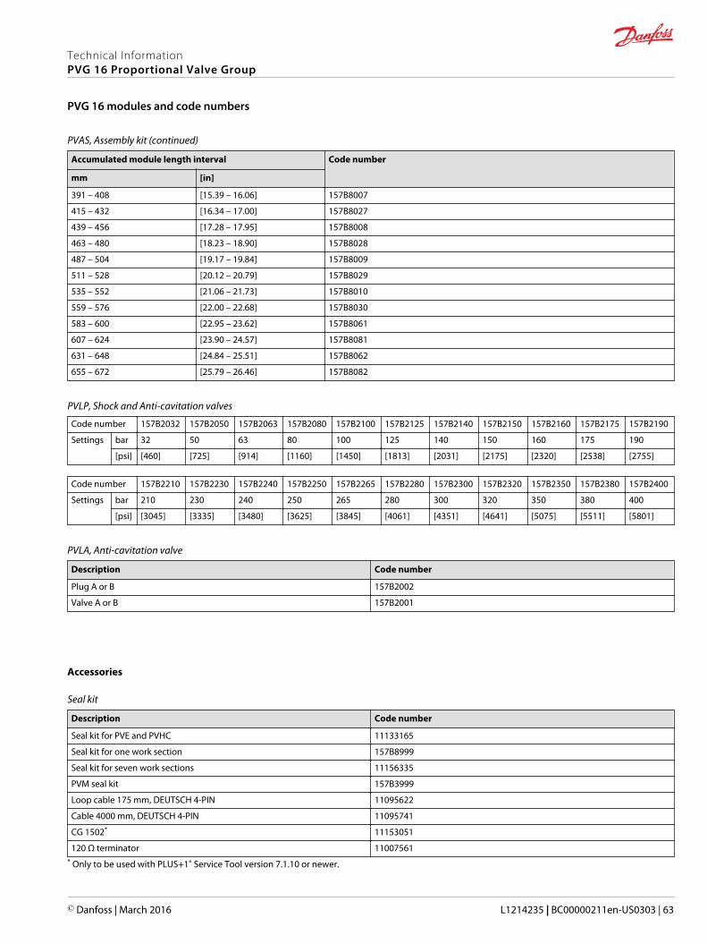
PVAS, Assembly kit (continued)
Accumulated module length interval Code number
mm [in]
391 – 408 [15.39 – 16.06] 157B8007
415 – 432 [16.34 – 17.00] 157B8027
439 – 456 [17.28 – 17.95] 157B8008
463 – 480 [18.23 – 18.90] 157B8028
487 – 504 [19.17 – 19.84] 157B8009
511 – 528 [20.12 – 20.79] 157B8029
535 – 552 [21.06 – 21.73] 157B8010
559 – 576 [22.00 – 22.68] 157B8030
583 – 600 [22.95 – 23.62] 157B8061
607 – 624 [23.90 – 24.57] 157B8081
631 – 648 [24.84 – 25.51] 157B8062
655 – 672 [25.79 – 26.46] 157B8082
PVLP, Shock and Anti-cavitation valves
Code number 157B2032 157B2050 157B2063 157B2080 157B2100 157B2125 157B2140 157B2150 157B2160 157B2175 157B2190
Settings bar 32 50 63 80 100 125 140 150 160 175 190
[psi] [460] [725] [914] [1160] [1450] [1813] [2031] [2175] [2320] [2538] [2755]
Code number 157B2210 157B2230 157B2240 157B2250 157B2265 157B2280 157B2300 157B2320 157B2350 157B2380 157B2400
Settings bar 210 230 240 250 265 280 300 320 350 380 400
[psi] [3045] [3335] [3480] [3625] [3845] [4061] [4351] [4641] [5075] [5511] [5801]
PVLA, Anti-cavitation valve
Description Code number
Plug A or B 157B2002
Valve A or B 157B2001
Accessories
Seal kit
Description Code number
Seal kit for PVE and PVHC 11133165
Seal kit for one work section 157B8999
Seal kit for seven work sections 11156335
PVM seal kit 157B3999
Loop cable 175 mm, DEUTSCH 4-PIN 11095622
Cable 4000 mm, DEUTSCH 4-PIN 11095741
CG 1502* 11153051
120 Ω terminator 11007561* Only to be used with PLUS+1® Service Tool version 7.1.10 or newer.
Technical InformationPVG 16 Proportional Valve Group
PVG 16 modules and code numbers
© Danfoss | March 2016 L1214235 | BC00000211en-US0303 | 63

Sectionv Function Extra Features
PVPp = bar
a PVM PVB PVBS cb LSA bar LSB bar b
a PVM PVB PVBS cb LSA bar LSB bar b
a PVM PVB PVBS cb LSA bar LSB bar b
a PVM PVB PVBS cb LSA bar LSB bar b
a PVM PVB PVBS cb LSA bar LSB bar b
a PVM PVB PVBS cb LSA bar LSB bar b
a PVM PVB PVBS cb LSA bar LSB bar b
a PVM PVB PVBS cb LSA bar LSB bar b
a PVM PVB PVBS cb LSA bar LSB bar b
11 End section PVS12 PVAS section PVAS
Comments:
Filled in by: Date:
9
7
8
4
5
6
10
2
3
1
PVLP/PVLA
PVE/PVH/PVMDPVLP/PVLA
v vB-Port
Application
A-Port
Subsidiary/DealerCustomer
Revision No.
PVG16
PVG No.Customer Part No.
PVLP/PVLAPVE/PVH/PVMD
PVLP/PVLA
PVE/PVH/PVMDPVLP/PVLA PVLP/PVLA
PVE/PVH/PVMDPVLP/PVLA PVLP/PVLA
PVE/PVH/PVMDPVLP/PVLA PVLP/PVLA
PVE/PVH/PVMDPVLP/PVLA PVLP/PVLA
PVE/PVH/PVMDPVLP/PVLA PVLP/PVLA
PVE/PVH/PVMDPVLP/PVLA PVLP/PVLA
PVE/PVH/PVMDPVLP/PVLA PVLP/PVLA
Technical InformationPVG 16 Proportional Valve Group
Order specification
64 | © Danfoss | March 2016 L1214235 | BC00000211en-US0303

Technical InformationPVG 16 Proportional Valve Group
© Danfoss | March 2016 L1214235 | BC00000211en-US0303 | 65
Technical InformationPVG 16 Proportional Valve Group
66 | © Danfoss | March 2016 L1214235 | BC00000211en-US0303
Technical InformationPVG 16 Proportional Valve Group
© Danfoss | March 2016 L1214235 | BC00000211en-US0303 | 67

Danfoss Power Solutions is a global manufacturer and supplier of high-quality hydraulic andelectronic components. We specialize in providing state-of-the-art technology and solutionsthat excel in the harsh operating conditions of the mobile off-highway market. Building onour extensive applications expertise, we work closely with our customers to ensureexceptional performance for a broad range of off-highway vehicles.
We help OEMs around the world speed up system development, reduce costs and bringvehicles to market faster.
Danfoss – Your Strongest Partner in Mobile Hydraulics.
Go to www.powersolutions.danfoss.com for further product information.
Wherever off-highway vehicles are at work, so is Danfoss. We offer expert worldwide supportfor our customers, ensuring the best possible solutions for outstanding performance. Andwith an extensive network of Global Service Partners, we also provide comprehensive globalservice for all of our components.
Please contact the Danfoss Power Solution representative nearest you.
Local address:
Danfoss Power Solutions GmbH & Co. OHGKrokamp 35D-24539 Neumünster, GermanyPhone: +49 4321 871 0
Danfoss Power Solutions ApSNordborgvej 81DK-6430 Nordborg, DenmarkPhone: +45 7488 2222
Danfoss Power Solutions (US) Company2800 East 13th StreetAmes, IA 50010, USAPhone: +1 515 239 6000
Danfoss Power Solutions Trading(Shanghai) Co., Ltd.Building #22, No. 1000 Jin Hai RdJin Qiao, Pudong New DistrictShanghai, China 201206Phone: +86 21 3418 5200
Danfoss can accept no responsibility for possible errors in catalogues, brochures and other printed material. Danfoss reserves the right to alter its products without notice. This also applies to productsalready on order provided that such alterations can be made without changes being necessary in specifications already agreed.All trademarks in this material are property of the respective companies. Danfoss and the Danfoss logotype are trademarks of Danfoss A/S. All rights reserved.
© Danfoss | March 2016 L1214235 | BC00000211en-US0303
Products we offer:
• Bent Axis Motors
• Closed Circuit Axial PistonPumps and Motors
• Displays
• Electrohydraulic PowerSteering
• Electrohydraulics
• Hydraulic Power Steering
• Integrated Systems
• Joysticks and ControlHandles
• Microcontrollers andSoftware
• Open Circuit Axial PistonPumps
• Orbital Motors
• PLUS+1® GUIDE
• Proportional Valves
• Sensors
• Steering
• Transit Mixer Drives
Comatrolwww.comatrol.com
Schwarzmüller-Inverterwww.schwarzmueller-inverter.com
Turolla www.turollaocg.com
Hydro-Gearwww.hydro-gear.com
Daikin-Sauer-Danfosswww.daikin-sauer-danfoss.com