proposal for collaboration subject: free form machining – tool path optimization university of...
TRANSCRIPT

Proposal for collaboration
Subject: Free form machining – tool path optimization
University of Belgrade, Serbia Faculty of Mechanical EngineeringDepartment of Production EngineeringCentre for New Technologies http://www.mas.bg.ac.rs/ http://cent.mas.bg.ac.rs/
MSc. Goran Mladenovic, PhD [email protected]. dr Ljubodrag Tanovic, PhD thesis [email protected]
INTRODUCTION• Free form surfaces are used in many areas of mechanical engineering.• Machining of free form surfaces can be done using 3 and 5 axis machines.• Commercial CAM software unfortunately cannot simulate tool damage or
overloading of axis servomotors.• The area of my research/thesis involves optimization of rough machining
with several criteria, one of them being feedrate scheduling.• This presentation gives a description of my recent research and proposal
for an experiment which results I intend to publish in collaboration with the University of Liverpool –Department of Physics colleagues, and of course use it as a massive/key contribution for my thesis.
• References– For feedrate scheduling
http://www.sciencedirect.com/science/article/pii/S2212827112000169– For example how to look forward paper
http://www.sciencedirect.com/science/article/pii/S0010448514000086#(STL file --> Tool path generation --> Experiment --> Measurment --> Analisys)

Tool path generation using commercial CAM software
Free form CAD model created by Solid Works
Pro/ENGINEER
SolidCAM
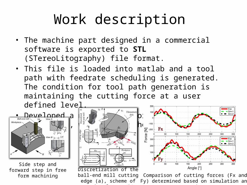
Work description • The machine part designed in a commercial software is exported to
STL (STereoLitography) file format.• This file is loaded into matlab and a tool path with feedrate
scheduling is generated. The condition for tool path generation is maintaining the cutting force at a user defined level.
• Developed a matlab code for cutting force prediction, which gives the results shown
Comparison of cutting forces (Fx and Fy) determined based on simulation and experiment
Discretization of the ball-end mill cutting edge (a), scheme
of cutting forces (b)
Side step and forward step in free form machining

Work flowchart
Free form surface (STL file format) generated in a commercial CAD software
MATLAB software
Generated tool path
Real machining
NC
code
Depiction of a machined part
Measurement
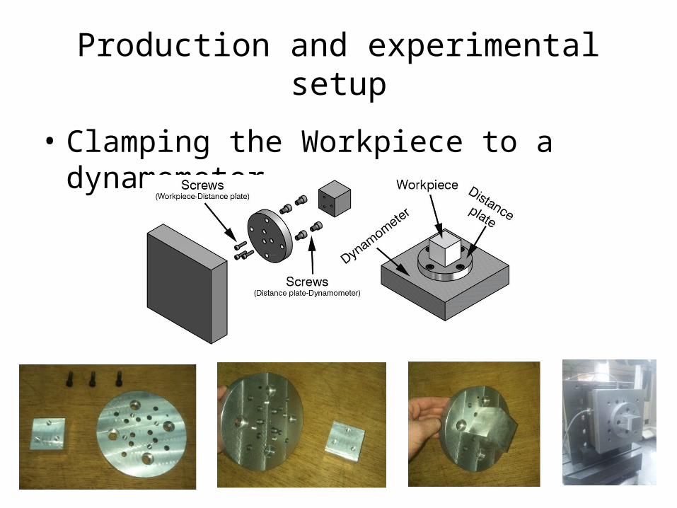
Production and experimental setup
• Clamping the Workpiece to a dynamometer

Experimental setup
The dependence of force in relation to movement
The dependence of force in relation to time
Detail G
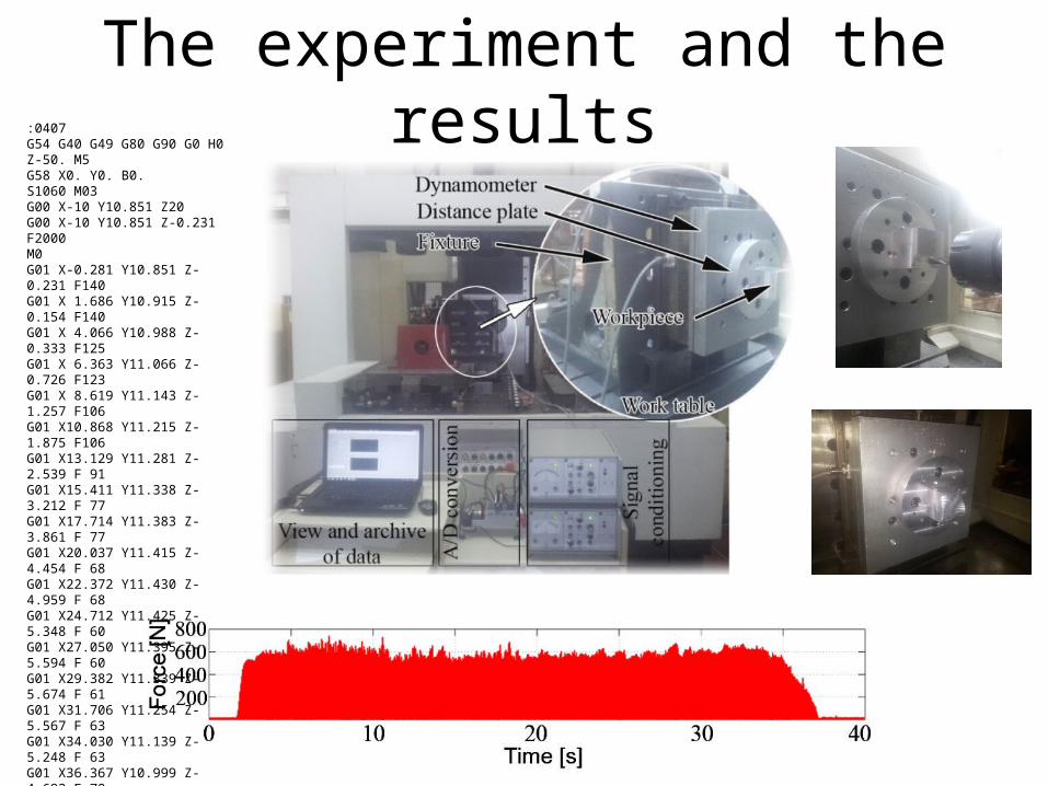
The experiment and the results:0407G54 G40 G49 G80 G90 G0 H0 Z-50. M5G58 X0. Y0. B0.S1060 M03G00 X-10 Y10.851 Z20G00 X-10 Y10.851 Z-0.231 F2000M0G01 X-0.281 Y10.851 Z-0.231 F140G01 X 1.686 Y10.915 Z-0.154 F140G01 X 4.066 Y10.988 Z-0.333 F125G01 X 6.363 Y11.066 Z-0.726 F123G01 X 8.619 Y11.143 Z-1.257 F106G01 X10.868 Y11.215 Z-1.875 F106G01 X13.129 Y11.281 Z-2.539 F 91G01 X15.411 Y11.338 Z-3.212 F 77G01 X17.714 Y11.383 Z-3.861 F 77G01 X20.037 Y11.415 Z-4.454 F 68G01 X22.372 Y11.430 Z-4.959 F 68G01 X24.712 Y11.425 Z-5.348 F 60G01 X27.050 Y11.395 Z-5.594 F 60G01 X29.382 Y11.339 Z-5.674 F 61G01 X31.706 Y11.254 Z-5.567 F 63G01 X34.030 Y11.139 Z-5.248 F 63G01 X36.367 Y10.999 Z-4.692 F 78G01 X38.736 Y10.839 Z-3.865 F 91G01 X41.157 Y10.668 Z-2.725 F112G01 X43.644 Y10.494 Z-1.219 F134G01 X46.426 Y10.284 Z 0.884 F144G01 X56 Y10.284 Z 0.884 F144G54 G40 G49 G80 G90 G0 H0 Z-50. M5M30

The needs for the proposed experiment
• 3 axis milling machine• Machine Vise• Ball-end cutter with a diameter of 12mm• Workpiece 50x50x50 mm or similar
– Material: AlMg4.5Mn ---------------------------------------------------------------------------------
If available:• Multicomponent Force Plate Piezo-Dynamometer for cutting force measurements
Example http://www.kistler.com/us/en/product/force/9257BA • Data acquisition system
Example http://www.ni.com/data-acquisition/
http://www.hbm.com/en/menu/products/measurement-electronics-software/compact-universal-data-acquisition-system/

Suggested steps
1. Machine the workpiece according to the NC code which I would send you already prepared.

Suggested steps2. Measure the machined part with a coordinate
measurment machine or an optical scanner (for the estimation of errors)
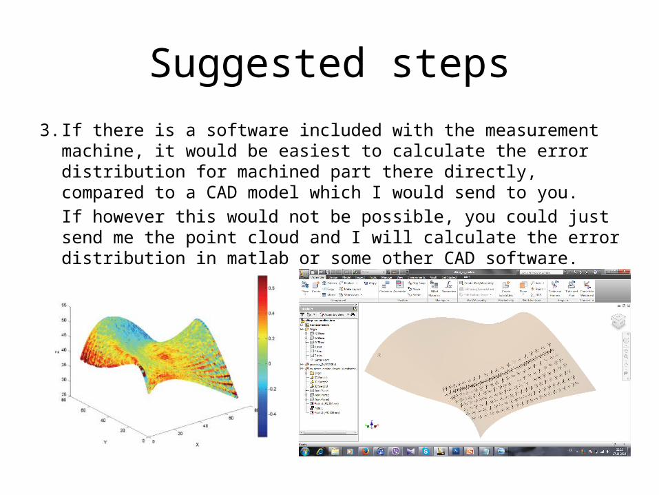
Suggested steps3. If there is a software included with the measurement machine, it
would be easiest to calculate the error distribution for machined part there directly, compared to a CAD model which I would send to you.If however this would not be possible, you could just send me the point cloud and I will calculate the error distribution in matlab or some other CAD software.

This would really mean a lot to me, and hopefully would be beneficial for both parties…
Thank you for your time!!
Sincerely yoursGoran Mladenovic