proposal for four power piston gamma type stirling engine
DESCRIPTION
Four power piston gamma type stirling engine design proposal for Universiti Sains Malaysia School of Mechanical Engineering System Design course.TRANSCRIPT

EMD 442 System DesignProposal
Four Power Piston HTD Gamma Stirling Engine
Group 3Name Matric no.
Yiauw Diing Shenq 111585
Muhamad Khairil Hafizi Bin Mohd Zorkipli 111549
Mohammad Fareez Bin Jaaffar 113606
Mohammad Nizar Bin Mohamed Zukri 111544
Lee Jin Liang 113605
School of Mechanical EngineeringLecturer: Dr. Mohamad Yusof Idroas
Date of Submission: 10th October 2014

Table of Contents
1.0 Problem Description...........................................................................................................1
2.0 Introduction.........................................................................................................................1
3.0 Objective..............................................................................................................................8
4.0 Design Methodology...........................................................................................................8
4.1 Heat Source.......................................................................................................................8
4.2 Displacer Cylinder............................................................................................................8
4.3 Power Piston Cylinder....................................................................................................10
4.4 Flywheel.........................................................................................................................10
4.5 Cooler.............................................................................................................................11
4.6 Heat Regenerator............................................................................................................12
4.7 Polyphase Generator.......................................................................................................14
4.8 Working Fluid.................................................................................................................15
5.0 Appendix............................................................................................................................17
6.0 References..........................................................................................................................19
1.0 Problem Description
The Stirling engine has attracted much attention over the years. Its potential for high
efficiency and the ability to use a wide variety of fuels has made it a serious contender for
alternative power sources, especially in automotive applications. The potential for Stirling
engines to replace the Internal Combustion Engine (ICE) in automobiles was explored in the
late 1970’s and 1980’s.
Kongtragool and Wongwises [1] built and presented the performance of a four
power-piston, gamma-configuration, low-temperature differential Stirling engine. Fig. 1
shows the schematics of the engine built by them. With an energy input of 1378 W and heater
temperature of 439 K, the engine produced a torque of 2.91 N m, 6.1 W maximum shaft
power, and a maximum brake efficiency of 0.44 % at 20 rpm. The four power-piston Stirling
engine gave rise to a question: Will more power piston give more power output and higher
efficiency?
In this project, we will investigate the correlation between number of power piston
and Stirling engine efficiency, the feasibility of four-power-piston configuration on High
Temperature Difference (HTD) Stirling engine, the engine layout, components design, and
components interaction to produce an electric output power of 1 kW. Calculations, graphs and
simulations using computer softwares will be used to verify and validate the proposed Stirling
engine system design.
2.0 Introduction
The Stirling engine were invented in 1816 by Robert Stirling [2] in Scotland, some 80
years ago before the invention of diesel engine. A Stirling cycle machine is a device, which
operates on a closed regenerative thermodynamic cycle, with cyclic compression and
expansion of the working fluid at different temperature levels. The flow is controlled by
volume changes so that there is a net conversion of heat to work or vice versa. In the
beginning of 19th century, due to the rapid development of internal combustion engines and
electrical machine, further development of Stirling engines was severely hampered.
High heat efficiency, low noise operation and ability of Stirling engines to use many
fuels meet the demand of the effective use of energy and environmental security [3]. Stirling
engine-based units are considered best among the most effective low-power range solar
thermal conversion units [4]. In 1980, with fuel crises, Stirling engines become a viable
proposition with rapid advances in material technology. This was the second stage of
transformation for the Stirling engines.
1

Kontragool and Wongwises [5] theoretically investigated the power output of a
gamma-configuration Low Temperature Difference (LTD) Stirling engine. Former works on
Stirling engine power output calculations were studied and discussed. They pointed out that
the mean-pressure power formula was the most appropriate for LTD Stirling engine power
output estimation. However, the hot-space and cold-space working fluid temperatures were
needed in the mean-pressure power formula.
Fig. 1 Four power-piston, gamma-configuration, low-temperature differential Stirling engine
schematics by Kontragool and Wongwises
Franco Normani [6] made a computer simulator based on FORTRAN language to
estimate the power output and efficiency of alpha, beta and gamma type Stirling engines. He
pointed out some design considerations in designing the heater, cooler, heat regenerator,
displacer cylinder, power piston cylinder, working fluid, and flywheel of Stirling engines.
Some calculations and optimised values for various parameters were presented in his work
based on the experimental work of previous researchers.
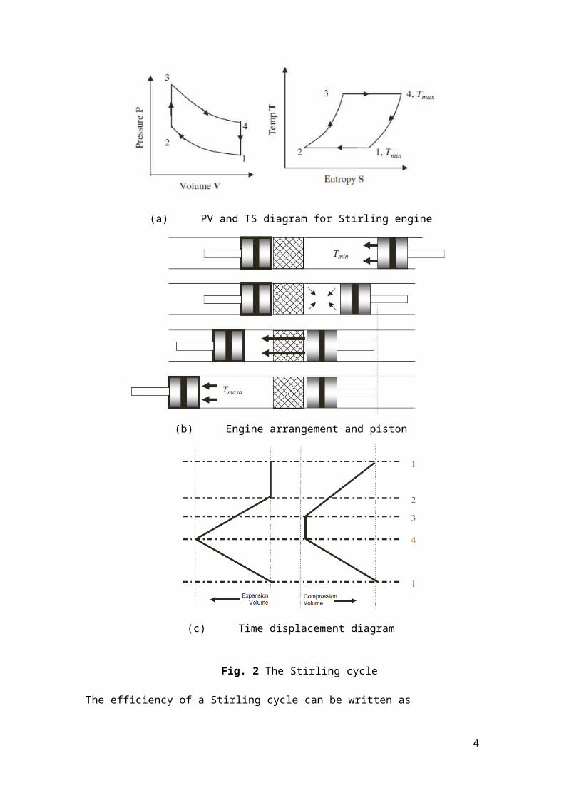
D. G. Thombare and S.K. Verma [7] presented the thermodynamics of Stirling engine
cycle. Fig. 2 shows the Stirling cycle. The work output of a Stirling cycle is defined by the
area of the cycle in the PV diagram.
2

(a) PV and TS diagram for Stirling engine
(b) Engine arrangement and piston
(c) Time displacement diagram
Fig. 2 The Stirling cycle
The efficiency of a Stirling cycle can be written as
3

ηt=mRT 3 ln (rv )−mRT 1 ln ( rv )
mRT 3 ln (rv )
ηt=1−T 1
T 3=1−
T min
Tmax=1−τ
D. G. Thombare and S.K. Verma [7] also presented the isothermal analysis of Stirling engine,
which is modelled by Urieli, Berchowitz consisting of compression space c, cooler k,
regenerator r, heater h, and expansion space e as shown in Fig. 3. The analysis assumed that
the total mass of working gas in the machine is constant.
Fig. 3 Ideal isothermal model
Where the work done by the engine over a complete cycle is the algebraic sum of the work
done by compression and expansion spaces.
W =W c+W e
W =∮ pd V c+∮ p d V e
W =∮ p ( d V c
dϕ+
d V e
dϕ )dϕ
Where ϕ is the crank angle.
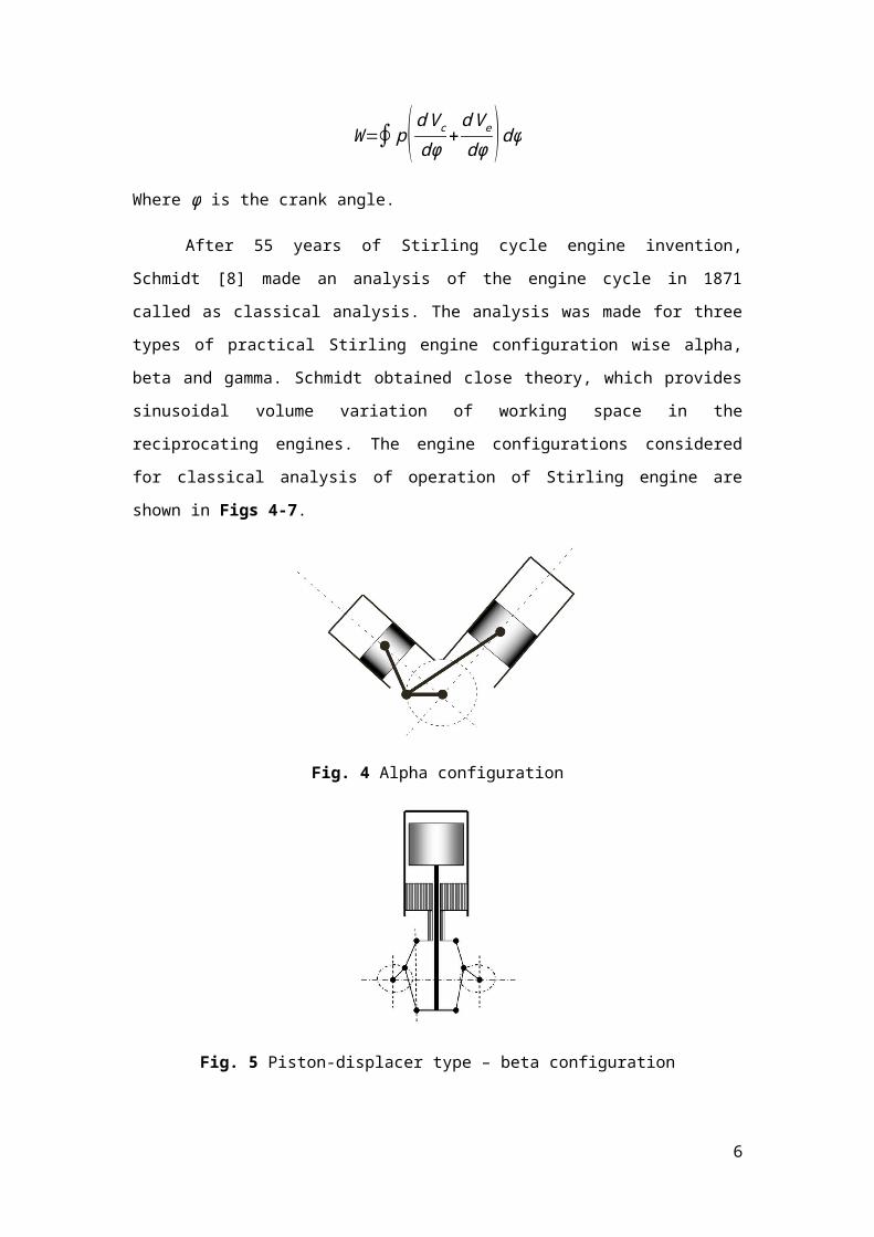
After 55 years of Stirling cycle engine invention, Schmidt [8] made an analysis of the
engine cycle in 1871 called as classical analysis. The analysis was made for three types of
4
practical Stirling engine configuration wise alpha, beta and gamma. Schmidt obtained close
theory, which provides sinusoidal volume variation of working space in the reciprocating
engines. The engine configurations considered for classical analysis of operation of Stirling
engine are shown in Figs 4-7.
Fig. 4 Alpha configuration
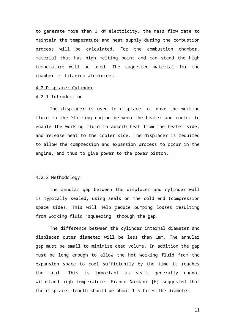
Fig. 5 Piston-displacer type – beta configuration
Fig. 6 Piston-displacer in separate cylinder – gamma configuration
5

Fig. 7 Schmidt’s analysis of a gamma-type Stirling engine
However in Schmidt’s theory, there are some principal assumptions in the analysis of Stirling
cycle engines:
1. All processes are reversible.
2. The regeneration process is perfect.
3. The working fluid obeys perfect gas law, pV=mRT .
4. The mass of air in the system remains constant, no leakage in the system.
5. The volume variation in the working space is sinusoidal.
6. There is no temperature gradient in the heat exchanger.
7. The cylinder wall and piston temperature are constant.
8. The speed of the machine is constant.
9. Steady state conditions are established.
10. There are no flow losses and hence no spatial pressure loss.
11. No leakage of working gas.
12. The temperature in heater and expansion space is isothermal at T E.
13. The temperature in cooler and compression space is isothermal at T C.
14. The temperature in the dead space and hence in regenerator space is isothermal.
William Beale [9] presented that in practice the maximum power output of well-
developed engine is roughly proportional to pressure, volume and speed. The Beale number is
BN=P i
PM V se N
However, one important factor that is not taken in to account by Beale correlation is the
temperature at which the engine is operated. Iwamoto [10] shows that Beale number is about
0.15 in case of high temperature differential Stirling engine whose heater wall temperature is
about 650 ° C. The effect of temperature is later considered by West, which the number is
defined as
6
W S=Pi
PM V SC N (T E−T C
T E+TC)
The West number is about 0.25 in case of 5-150 kW Stirling engines and is about 0.35 in case
of smaller power engines.
This proposal will present the design methodology to design a four-power-piston,
gamma configuration, high temperature difference Stirling engine which can produce 1 kW of
electrical power output. The proposed system will consist of the design of the heat source,
displacer cylinder, power piston cylinder, flywheel, cooler, heat regenerator, polyphase
electric generator, and the working fluid to fulfil the required specifications. Calculations and
analysis of the Stirling cycle engine will be made based on Schmidt’s analysis, as provided in
the Appendix section. The expected outcome from the design will be the Beale and West
numbers, along with calculations to support the concept of a 1 kW Stirling engine.
7

3.0 Objective
The objective of this project is to design a system which will be powered using a
four-power-piston, gamma-configuration, HTD Stirling engine to produce 1 kW of electrical
power output.
4.0 Design Methodology
4.1 Heat Source
4.1.1 Introduction
External heat is needed by the Stirling engine to generate electrical power. External
combustion is the example of the external heat supply to the engine. The biomass is needed in
the combustion to supply heat to the engine. The heat conductive mechanism needed in the
heat supply system.
4.1.2 Methodology
The group have done some research on designing the heat combustion chamber and
the heat sources which are the biomass. The sites and journals on the design the heat
combustion chamber and the heat sources have been gone through. For this design, the group
will use biomass as external burning fuels to generate heat for the Stirling engine. There are 2
main parameters that need to consider in designing the heat transfer system which are the
external combustion chamber and the mechanism of inner tube to transfer the heat to the roof.
There also have to include the heat transfer coefficient and the friction factor.
The group will find some example of the biomass that can be used in this project. The
biomass examples are rise husks, bagasse, rice straw, wood and coconut shell. The mass
needed to generate more than 1 kW electricity, the mass flow rate to maintain the temperature
and heat supply during the combustion process will be calculated. For the combustion
chamber, material that has high melting point and can stand the high temperature will be used.
The suggested material for the chamber is titanium aluminides.
4.2 Displacer Cylinder
4.2.1 Introduction
The displacer is used to displace, or move the working fluid in the Stirling engine
between the heater and cooler to enable the working fluid to absorb heat from the heater side,
and release heat to the cooler side. The displacer is required to allow the compression and
expansion process to occur in the engine, and thus to give power to the power piston.
8

4.2.2 Methodology
The annular gap between the displacer and cylinder wall is typically sealed, using
seals on the cold end (compression space side). This will help reduce pumping losses
resulting from working fluid “squeezing” through the gap.
The difference between the cylinder internal diameter and displacer outer diameter
will be less than 1mm. The annular gap must be small to minimize dead volume. In addition
the gap must be long enough to allow the hot working fluid from the expansion space to cool
sufficiently by the time it reaches the seal. This is important as seals generally cannot
withstand high temperature. Franco Normani [6] suggested that the displacer length should be
about 1.5 times the diameter.
However having a long gap will result in a loss in thermal efficiency of the engine.
This is due to the heat loss that occurs when hot gas flows into the gap and loses heat to the
colder displacer and cylinder wall. Thus, a metal ring, or also called a “hot ring” will be
added around the displacer at the hot end. This helps prevent hot working gas from flowing
into the gap during the displacer motion. The ring will be made of a wear resistant alloy
which will be able to operate well without lubrication at high temperatures. Fig. 8 shows the
cross sectional view of the proposed displacer cylinder.
Fig. 8 Cross sectional view of the proposed displacer cylinder
9

4.3 Power Piston Cylinder
4.3.1 Introduction
The power piston is the power producer for the engine, where it is connected in 90°
difference in phase angle with respect to the displacer rod on the flywheel. The compressed
working fluid from the displacer creates a pressure on the power piston, which creates a force
on the piston and piston rod. The force is the transmitted to the flywheel of the Stirling engine
to turn the flywheel, thus producing power with similar concept as the power stroke of an
internal combustion engine.
4.3.2 Methodology
In theory, the larger the power piston (hence the larger the swept volume), the more
power will be generated by the Stirling engine. However in practical cases, it is not true due
to the following reasons.
First, there will be more friction with the larger piston or longer stroke. As the
Stirling engine revs up, the effect of friction becomes more significant, and this may lead to a
lower net power as we plot the power curve for the engine.
Second, the higher the compression, the more likely the engine will experience power
loss due to gas leaks past the piston. Gas leaks past the piston reduce the pressure ratio and
will reduce engine power even at low compression. The losses become greater as the
compression increases.
Therefore, the four power pistons will be designed to maximize power output while
keeping the surface area in contact between the pistons and the cylinder wall at minimum.
Also, oil sealing will be used to prevent the working fluid from escaping the piston cylinder,
thus reducing gas leaks and enhancing engine efficiency.
4.4 Flywheel
4.4.1 Introduction
Selecting a flywheel of suitable size and mass is an important aspect of the design of
Stirling engines. It has to be “heavy” enough to absorb energy from the engine during the
power stroke (without speeding up too much) and then use that energy to “push” through the
compression stroke (without slowing down too much). A proper flywheel will minimize
fluctuations in rotational speed. This is necessary to ensure “smooth” engine operation. If the
flywheel is not heavy enough the engine rotation will be “jerky” and engine performance will
be poor.
10

4.4.2 Methodology
The goal is the design a flywheel that is heavy enough to do the job but is not too big
and heavy. The “heaviness” of a flywheel is referring to its rotational inertia about its center
of rotation. Therefore, the flywheel needs to have high rotational inertia while keeping the
mass as low as possible. This will be accomplished by using a flywheel with a solid outer rim,
in which most of the mass will be concentrated around the outside. Fig. 9 shows the basic
flywheel design for Stirling engines.
Fig. 9 Basic flywheel design for Stirling engines
Mathematically, the rotational inertia of the flywheel is given by:
I=m r2
Where m is the mass of the outer rim. So from the equation, to achieve a light-weight
flywheel, the flywheel will have a large radius with 90% of its total mass in the outer rim, and
only 10% of its mass in the inside hub for support.
4.5 Cooler
4.5.1 Introduction
Cooler part is essential part in Stirling engines to provides a sufficiently low temperature
consistently and remove heat from the system to keep the cycle running. To obtain the highest
temperature difference, cooler is designed as external system [12]. There is elevation on the
temperature so that the thermal efficiency is should be considered. Hence, the coolant’s
temperature need to be designed as minimum as possible beside to obtain the high
temperature difference [13]. The flow condition is similar as a heater but at the lower
11
temperature. The main concept is heat exchanger. To cool down the fluid in cooler part,
coolant (air, water and etc.) passing through the compression space where it is absorbs heat.
Heat is removed in one medium and transferred to another medium [8]. By the previous
researcher, it was found that in purpose to design 1kw Stirling gamma type engine, the
temperature difference is 590 °C whereas the working fluid at heater part around 650 °C and
working fluid in cooler part is around 60 °C [14].
4.5.2 Methodology
1. Study on heat exchanger and heat transfer;
2. Design flow process of cooler (coolant absorb heat > inlet of radiator tank > heat
distribute to core (copper-fins and brass-tube) > coolant go to another tank (cool
again) > coolant fed back (cycle repeat));
3. Equipment: tube, tank, water (coolant), core and fan (convection mechanism), and
water pump;
4. Analyze heat that is absorbed by coolant (water), total heat transfer coefficient
(parameter: water thermal conductivity, diameter of tube and etc.);
5. Summarize and get the temperature difference.
4.6 Heat Regenerator
4.6.1 Introduction
A regenerator is typically made of a dense matrix consisting of stacked metal screens,
or metal felt, woven from fine wires. This provides the high heat transfer capability needed to
“store” and “release” heat. It separates both sources of heat and operate as a thermal sponge
which accepts and rejects heat from the working fluid. The way the regenerator works is by
storing some of the heat energy of the working gas as it moves from the heater to the cooler.
From the studies, Stirling engine efficiency and heat input are affected by both regenerator
effectiveness and dead volumes.
Fig. 4: Example of regenerator design that commonly used in Stirling engine.
12

From Fig. 4, it shows void volume and regenerator matrix. These two parameters are
very important in determined the efficiency of the Stirling engine. The “regenerator void
volume is simply the volume of empty space inside the regenerator housing. This is the space
is not “filled” with matrix material. Regenerator matrix is choose from material that have high
thermal conductivity which mean the materials can absorbs heat as much as possible.
Besides, there are also tubes inside the regenerator housing. The purpose of these
tubes is to transfer the working fluids. The main benefits using a large number of tubes is that
it “splits” up the flow and reduces pumping (flow) losses.
4.6.2 Methodology
The group has done some researches on designing of the regenerator for Stirling
engine. Many journals that are related to regenerator were found at directscience.com website.
Based on the studies, regenerator is a must component in the Stirling engine, since the
working principle of this engine operates from the external burning of fuels.
First of all, to design regenerator the components or parameters inside the regenerator
housing must be known. There are basically 4 main parameters we need to consider in
designing a good regenerator named as void volume, number of tube, matrix material and
regenerator housing.
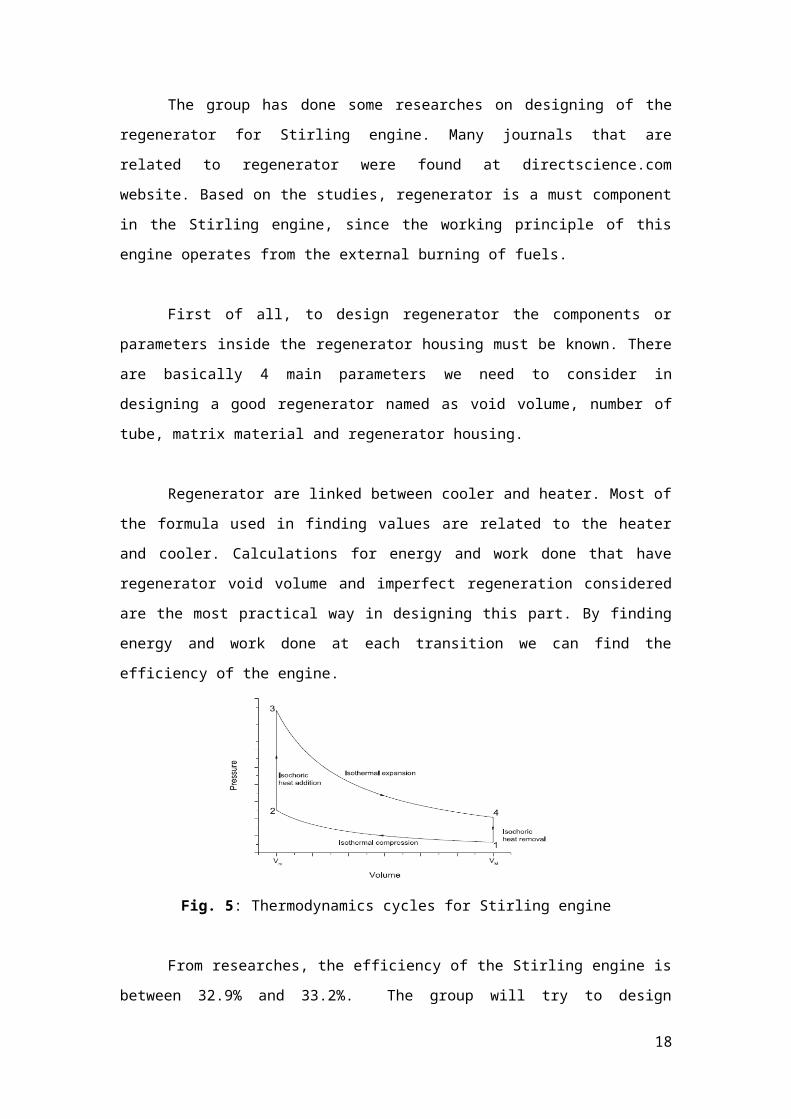
Regenerator are linked between cooler and heater. Most of the formula used in
finding values are related to the heater and cooler. Calculations for energy and work done that
have regenerator void volume and imperfect regeneration considered are the most practical
way in designing this part. By finding energy and work done at each transition we can find
the efficiency of the engine.
Fig. 5: Thermodynamics cycles for Stirling engine
13

From researches, the efficiency of the Stirling engine is between 32.9% and 33.2%.
The group will try to design regenerator that can increase the efficiency or exactly the same as
stated in most journals. By knowing the efficiency, the next step we can calculate the size or
dimension of the housing regenerator and void volume that are related to some of the work
done and energy formula. A spreadsheet calculator is created for regenerator to achieve our
target values to get the highest efficiency. Among the parameters that need to be changed in
order to achieve highest efficiency possible is void volume, regenerator housing, volume of
matrix materials and number of tubes.
The group also takes account the type of materials that will be used for matrix.
Stainless steel is the most common material used for matrix material due to its high heat
capacity and thermal exchange rate. The most suitable materials that have high thermal
conductivity will be used. The higher the thermal conductivity of the material the more heat
can be transferred per second. The regenerator housing will be insulated with low thermal
conductivity materials so that heat cannot escape to surrounding. Nickel-copper alloy is one
the materials that will be taken into considerations for matrix material because of its good
material properties.
4.7 Polyphase Generator
4.7.1 Introduction
Based on the study on a website [14], the working principle of a polyphase motor is
being reversed to become a polyphase generator to generate electrical energy from
mechanical energy by rotating permanent magnet rotor. In the documentation, there are a lot
of details information about the phase coil connections, phase arrangements and mechanical-
to-electrical energy conversion, which include all associated calculations for the critical
parameters and conflicting factors in determining the most appropriate specifications and
structure design of polyphase generator with optimum performance in conjunction with the
gamma Stirling engine system design.
Reverse motor requires a commutator and brushes in order periodically to reverse the
current through each armature coil. However, the brushes have to be periodically changed and
the commutator resurfaced due to wear as a consequence of the sliding contacts between the
brushes and commutator. To avoid such problem brushless permanent magnet generator is
preferred. With the brushless permanent magnet generator, the current-carrying inductive
coils are fixed and the permanent magnet rotor rotates.
14

A generator is basically a device that converts mechanical energy to electrical energy.
Polyphase generator allows us to decide the number of phases required, number of poles of
permanent magnet needed and the associated number of coils as well based on the specific
ratio of mechanical-to-electrical energy conversion.
Besides, phase arrangements also play an important role in the performance of a
polyphase generator. There are multiple ways to arrange the wiring of a polyphase generator,
but mostly based on two basic configurations, the delta and Y circuit arrangements. What
mainly differentiates delta and Y system is the connection of their phase coil groups to obtain
the optimum power and efficiency with minimal self-interference which will be discussed in
details after further verifications on the performance parameters involved.
4.7.2 Methodology
There are some conflicting factors that we have to trade off when choosing the most
appropriate phase arrangement for the generator to achieve desired performance. Before that,
we need to consider our design constraints and the ultimate goal of the overall design system,
such as the ways that the design constraints the performance’s parameters and followed by
optimization of the critical parameters and also investigation of the key risk variables when
the polyphase generator is work together with the gamma Stirling engine.
Polyphase generator is basically an AC generator, but most of the electrical devices
are powered by DC source. We will also look into the AC to DC conversion in order to
achieve 1kW effective power. Furthermore, we will try to map the design outcome with the
generators available in the market for comparison and as a reference for more reliable design
of the polyphase generator in order to complete the gamma Stirling engine system for more
practical applications.
4.8 Working Fluid
4.8.1 Introduction
Any working fluid with high specific heat capacity may be used for Stirling cycle
engine. With few exceptions the engines in 19th century used air as working fluid. Most of
them operated close to atmospheric temperature. The working fluid in a Stirling engine
should have flowing thermodynamic, heat transfer and gas dynamic properties:
1. High thermal conductivity
2. High specific heat capacity
3. Low viscosity
4. Low density
15

However, for a better system performance in addition to above, ease of availability,
cost, safe operation, storage requirements are also important properties. The capability of
working fluid in terms of specific heat capacity, thermal conductivity and density is defined
by Martini [15] and Clarke [16] which is useful for preliminary selection of working fluid.
Capability factor= Thermal conductivitySpecific heat capacity × Density
4.8.2 Methodology
In Table 1 [7], various fluids are compared using capability factor as mentioned above.
Table 2 [7] shows the specific heat and specific heat ratios of various working fluid. From
both tables, it can be seen that Sodium-Potassium (NaK) eutectic has 32 times the heat
transfer capability than air, also with the highest capability factor. Therefore, NaK eutectic
will be chosen as the working fluid for the Stirling engine to be designed.
Table 1 Relative heat transfer characteristics for various gases
Table 2 Relative performance of selected working fluid
16

5.0 Appendix
Calculation Model of a Gamma-type Stirling Engine
Expansion momental volume:
V E=V SE
2(1−cos x )+V DE
Compression momental volume:
V c=V SE
2(1+cos x )+
V SC
2{1−cos (x−dx )}+V DC
Total momental volume:
V=V E+V R+V C
Engine pressure:
P=Pmin √1−c2
1−c .cos( x−a)=
Pmin (1+c )1−c .cos (x−a )
=Pmin (1−c )
1−c . cos ( x−a )
Temperature ratio:
t=Tc
T E
Swept volume ratio:
v=V SC
V SE
Dead volume ratio (Expansion):
X DE=V DE
V SE
Dead volume ratio (Compression):
X DC=V DC
V SE
Volume ratio (Regeneration):
X R=V R
V SE
Coefficients:
a= tan−1 v sin dxt+cosdx−1
S= t+2 t X DE+4 t V R
1+ t+v+2 X DC+1
17

B=√t 2+2 (t−1 ) v cosdx+v2−2 t+1
c= BS
Indicated Energy, Power and Efficiency
Indicated expansion energy:
W E=Pmax V SE πc . sin a
1+√1−c2. √1−c√1+c
Indicated compression energy:
W c=Pmax V SE πct . sin a
1+√1−c2. √1−c√1+c
Indicated energy per cycle of the engine:
W i=W e+W c=Pmax V SE πc (1−t)sin a
1+√1−c2. √1−c√1+c
Relations between Pmean, Pmin and Pmax:
Pmin
Pmean=√ 1−c
1+c
Pmax
Pmean=√ 1+c
1−c
Indicated expansion power:
LE=W E n
Indicated compression power:
LC=W C n
Indicated power of the engine:
Li=W i n
Efficiency of the engine:
e=W i
W E=1−t
18
6.0 References
1. Kongtragool, B., Wongwises, S., 2007b. Performance of a twin power piston low
temperature differential Stirling engine powered by a solar simulator. Solar Energy
81, 884–895.
2. Robert Stirling, Patent no. 4081, Stirling air engine and the heat regenerator, 1816.
3. Pertescu S, Coastea M, Harman C, Florea T. Application of the direct method to
irreversible Stirling cycle with finite speed. Energy Convers Conserv Environ Impact
2002:589–609.
4. Mancini T, Heller P. Dish Stirling systems: an overview of development and status.
Trans ASME 2003;125:135–51.
5. Shoureshi R, Paynter HM. Low temperature Stirling engine for waste heat recovery.
Seventeenth intersociety energy conversion engineering conference, vol. 829284;
1982. p. 1716–20.
6. Normani, F., 2013. Stirling Engine Manual.
7. D.G. Thombarea, S.K. Vermab 2006, Technological development in the Stirling
cycle engines, Renewable & Sustainable Energy Reviews, Rajarambapu Institute of
Technology and Dr. Babasabeb Ambedkar Technological University.
8. Schmidt G. Classical analysis of operation of Stirling engine. A report published in
German Engineering Union (Original German), vol. XV; 1871. p. 1–12.
9. Beale WT, Wood JG, Chagnot BF. Stirling engine for developing countries.
American Institute of Aeronautics and Astronautics 1980;809399:1971–5.
10. Iwamoto S, Hirata K, Toda F. Performance of Stirling engines. JSME Int J
2001;44(1):140–7.
11. WORCESTER POLYTECHNIC INSTITUTE, Design of stirling engine for
electricity generation;
12. Main article: Radiator (cooler), Wikipedia.
13. Luca RAGGI, Masafumi KATSUTA, DESIGN OF A 1 KW CLASS GAMMA
TYPE STIRLING ENGINE.
14. Web link: https://web.stanford.edu/~hydrobay/lookat/pmg.html
15. Martini WR. Stirling engine design manual. Martini Engineering Publication.
16. Clarke MA, Reader GT, Taylor DR. Experiences in the commissioning of a prototype
20kW helium charged Stirling engine. Seventeenth intersociety energy conversion
engineering conference, vol. 829298; 1982. p. 1796–1800.
19