proposal for upgrading/introducing...
TRANSCRIPT

Proposal for Upgrading/Introducing Inverters
HEAD OFFICE: TOKYO BLDG., 2-7-3, MARUNOUCHI, CHIYODA-KU, TOKYO 100-8310, JAPAN
Mitsubishi Electric Corporation Nagoya Works is a factory certified for ISO14001 (standards for environmental management systems) and ISO9001 (standards for quality assurance management systems).
L(NA)06096ENG-B(1610) MEE
FACTORY AUTOMATION

2
4
6
8
8
9
9
10
11
12
Proposal for Inverter Control
Upgrading Existing Inverters
Upgrading from Machinery Systems Driven by Commercial Power Supply
Upgrading from Wound Rotor Motor Systems
Upgrading from Eddy Current Coupling Motor (AS Motor) Systems
Upgrading from Direct Current Motor Systems
Mitsubishi Inverter Family Products
Further Energy Saving Operation with Premium High-efficiency IPM Motor
Solutions for Maintenance/Inspection of Inverters, Upgrading, and Total System Configuration
Global Player Contents
GLOBAL IMPACT OFMITSUBISHI ELECTRIC
We bring together the best minds to create the best technologies. At Mitsubishi Electric, we understand that technology is the driving force of change in our lives. By bringing greater comfort to daily life, maximiz-ing the efficiency of businesses and keeping things running across society, we integrate technology and innovation to bring changes for the better.
Mitsubishi Electric is involved in many areas including the following
Energy and Electric SystemsA wide range of power and electrical products from generators to large-scale displays.
Electronic DevicesA wide portfolio of cutting-edge semiconductor devices for systems and products.
Home ApplianceDependable consumer products like air conditioners and home entertain-ment systems.
Information and Communication SystemsCommercial and consumer-centric equipment, products and systems.
Industrial Automation SystemsMaximizing productivity and efficiency with cutting-edge automation technology.
Through Mitsubishi Electric’s vision, “Changes for the Better“ are possible for a brighter future.

3
4
6
8
8
9
9
10
11
12
Proposal for Inverter Control
Upgrading Existing Inverters
Upgrading from Machinery Systems Driven by Commercial Power Supply
Upgrading from Wound Rotor Motor Systems
Upgrading from Eddy Current Coupling Motor (AS Motor) Systems
Upgrading from Direct Current Motor Systems
Mitsubishi Inverter Family Products
Further Energy Saving Operation with Premium High-efficiency IPM Motor
Solutions for Maintenance/Inspection of Inverters, Upgrading, and Total System Configuration
Global Player Contents
GLOBAL IMPACT OFMITSUBISHI ELECTRIC
We bring together the best minds to create the best technologies. At Mitsubishi Electric, we understand that technology is the driving force of change in our lives. By bringing greater comfort to daily life, maximiz-ing the efficiency of businesses and keeping things running across society, we integrate technology and innovation to bring changes for the better.
Mitsubishi Electric is involved in many areas including the following
Energy and Electric SystemsA wide range of power and electrical products from generators to large-scale displays.
Electronic DevicesA wide portfolio of cutting-edge semiconductor devices for systems and products.
Home ApplianceDependable consumer products like air conditioners and home entertain-ment systems.
Information and Communication SystemsCommercial and consumer-centric equipment, products and systems.
Industrial Automation SystemsMaximizing productivity and efficiency with cutting-edge automation technology.
Through Mitsubishi Electric’s vision, “Changes for the Better“ are possible for a brighter future.

4
For details, see page 6 and page 7. For details, see page 8.
Oh no!
Did
you know?
Parts supply limit has been reached!
Use inverters for driving standard motors.
Oh, my!Maintenance,
again.
Inverters have their service life. Also, the
supply limit is set for parts.
Owing to the upgrade, the line does not stop.
It's a pleasureto be helping you.
Thanks forthe help!
Just in case... Operation as the situationdemands.Operation as the situationdemands.
Maintenance-free!Maintenance-free!
The starting currentis also reduced.The starting currentis also reduced.Use the latest model to feel at ease.Use the latest model to feel at ease.
Ina 24-hour operating
environment
fullcapacity
operation is not required
all day.
EasyinstallationInverter
Day
NightExcellent energy
saving effect!
Brush
Magnet
Ma
et
Brushless
and
contactless
with inverter
drive.
Brush
For details, see page 8.
For conventionalinverter system users
For commercial powersupply system users
For wound rotormotor users
For details, see page 9. For details, see page 11.For details, see page 9.
Although it is difficult to obtain this type of motors,
they are still being fully used.
think of energy saving.
Energy saving by driving standard motors by inverters!
Downsized!
But, it's time to
The time to reduce CO2 emissons is now...
With the IPM motor...Significant energy saving and CO2 reduction can be achieved.
You can contribute to global warning prevention.You can contribute to global warning prevention.
Maintenance and preventive maintenance...
Any good ideas?
Loss
Heat
It is quite a task to teach how to maintain the motor.
Brush?
Using an inverterfor speed control may be helpful!
If you change your motors, consider the use of IPM motors.
For eddy current couplingmotor (AS motor) users
For direct current (DC)motor users
For prospectiveIPM motor users
Proposal for Inverter ControlDo you want to improve the existing machinery?
Case studiesBenefits of upgrading systems with different types of motors
Machines with motors are used in various applications such as driving conveyors or operating fans.If you consider upgrading your machines, we recommend incorporation of "inverter control" into your system to enable optimal motor control by energy saving operation or a soft start function.Furthermore, requests to achieve "a little bit more advanced operation" or "energy saving operation" without changing the existing facility can be relatively easily managed by using general-purpose inverters with the existing system. You can gain great advantages.
INVERTER

5
For details, see page 6 and page 7. For details, see page 8.
Oh no!
Did
you know?
Parts supply limit has been reached!
Use inverters for driving standard motors.
Oh, my!Maintenance,
again.
Inverters have their service life. Also, the
supply limit is set for parts.
Owing to the upgrade, the line does not stop.
It's a pleasureto be helping you.
Thanks forthe help!
Just in case... Operation as the situationdemands.Operation as the situationdemands.
Maintenance-free!Maintenance-free!
The starting currentis also reduced.The starting currentis also reduced.Use the latest model to feel at ease.Use the latest model to feel at ease.
Ina 24-hour operating
environment
fullcapacity
operation is not required
all day.
EasyinstallationInverter
Day
NightExcellent energy
saving effect!
Brush
Magnet
Ma
et
Brushless
and
contactless
with inverter
drive.
Brush
For details, see page 8.
For conventionalinverter system users
For commercial powersupply system users
For wound rotormotor users
For details, see page 9. For details, see page 11.For details, see page 9.
Although it is difficult to obtain this type of motors,
they are still being fully used.
think of energy saving.
Energy saving by driving standard motors by inverters!
Downsized!
But, it's time to
The time to reduce CO2 emissons is now...
With the IPM motor...Significant energy saving and CO2 reduction can be achieved.
You can contribute to global warning prevention.You can contribute to global warning prevention.
Maintenance and preventive maintenance...
Any good ideas?
Loss
Heat
It is quite a task to teach how to maintain the motor.
Brush?
Using an inverterfor speed control may be helpful!
If you change your motors, consider the use of IPM motors.
For eddy current couplingmotor (AS motor) users
For direct current (DC)motor users
For prospectiveIPM motor users
Proposal for Inverter ControlDo you want to improve the existing machinery?
Case studiesBenefits of upgrading systems with different types of motors
Machines with motors are used in various applications such as driving conveyors or operating fans.If you consider upgrading your machines, we recommend incorporation of "inverter control" into your system to enable optimal motor control by energy saving operation or a soft start function.Furthermore, requests to achieve "a little bit more advanced operation" or "energy saving operation" without changing the existing facility can be relatively easily managed by using general-purpose inverters with the existing system. You can gain great advantages.
INVERTER
INVERTER
6
Upgrading Existing Inverters
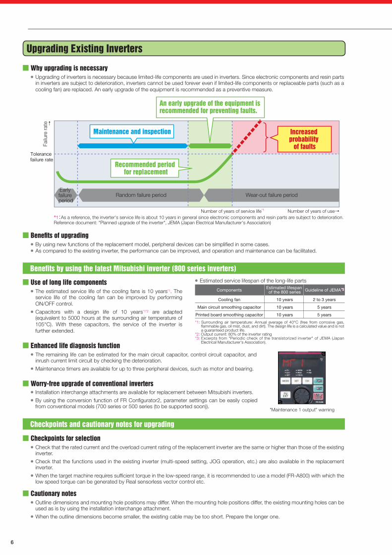
Why upgrading is necessary● Upgrading of inverters is necessary because limited-life components are used in inverters. Since electronic components and resin parts
in inverters are subject to deterioration, inverters cannot be used forever even if limited-life components or replaceable parts (such as a cooling fan) are replaced. An early upgrade of the equipment is recommended as a preventive measure.
● Estimated service lifespan of the long-life parts
*1: Surrounding air temperature: Annual average of 40°C (free from corrosive gas, flammable gas, oil mist, dust, and dirt). The design life is a calculated value and is not a guaranteed product life.
*2: Output current: 80% of the inverter rating*3: Excerpts from "Periodic check of the transistorized inverter" of JEMA (Japan
Electrical Manufacturer's Association).
Checkpoints for selection● Check that the rated current and the overload current rating of the replacement inverter are the same or higher than those of the existing
inverter.● Check that the functions used in the existing inverter (multi-speed setting, JOG operation, etc.) are also available in the replacement
inverter.● When the target machine requires sufficient torque in the low-speed range, it is recommended to use a model (FR-A800) with which the
low speed torque can be generated by Real sensorless vector control etc.
Cautionary notes● Outline dimensions and mounting hole positions may differ. When the mounting hole positions differ, the existing mounting holes can be
used as is by using the installation interchange attachment.● When the outline dimensions become smaller, the existing cable may be too short. Prepare the longer one.
Enhanced life diagnosis function● The remaining life can be estimated for the main circuit capacitor, control circuit capacitor, and
inrush current limit circuit by checking the deterioration.● Maintenance timers are available for up to three peripheral devices, such as motor and bearing.
Benefits of upgrading● By using new functions of the replacement model, peripheral devices can be simplified in some cases.● As compared to the existing inverter, the performance can be improved, and operation and maintenance can be facilitated.
Use of long life components● The estimated service life of the cooling fans is 10 years*1. The
service life of the cooling fan can be improved by performing ON/OFF control.
● Capacitors with a design life of 10 years*1*2 are adapted(equivalent to 5000 hours at the surrounding air temperature of 105°C). With these capacitors, the service of the inverter is further extended.
Worry-free upgrade of conventional inverters● Installation interchange attachments are available for replacement between Mitsubishi inverters.● By using the conversion function of FR Configurator2, parameter settings can be easily copied
from conventional models (700 series or 500 series (to be supported soon)).
Benefits by using the latest Mitsubishi inverter (800 series inverters)
Checkpoints and cautionary notes for upgrading
Components
Cooling fan
Main circuit smoothing capacitor
Printed board smoothing capacitor
Estimated lifespan of the 800 series
10 years
10 years
10 years
Guideline of JEMA
2 to 3 years
5 years
5 years
"Maintenance 1 output" warning
↑
Failu
re r
ate
Number of years of use→
Random failure periodEarly failure period
Wear-out failure period
Maintenance and inspection
An early upgrade of the equipment is recommended for preventing faults.
Recommended period for replacement
Increased probability
of faultsTolerance failure rate
Number of years of service life*1
*1:As a reference, the inverter's service life is about 10 years in general since electronic components and resin parts are subject to deterioration.Reference document: "Planned upgrade of the inverter", JEMA (Japan Electrical Manufacturer's Association)
*3*3
List of alternative models for the conventional series
Conventional series nameProduction termination
scheduleRepair componentssupply termination
Alternative model
*1: For the operation where the inverter output current exceeds 120% of its rated current, select the FR-A800 series.
FR-F2
FR-K
FR-K400
FR-F300
FR-K3
FR-E
FR-Z020
FR-Z300
FR-Z100
FR-Z123
FR-F400
FR-A200
FR-Z024
FR-V200
FR-A100
FR-Z200
FR-A200E
MT-A100E
FR-A100E
MT-A200E
FR-U100
FR-S500 (Three-phase 200 V)
FR-V200E
FR-S500(Three-phase 400 V / single-phase 200 V / single-phase 100 V)
FR-F500 (L)
FR-A500 (L)
FR-A024/A044
FR-A201E
FR-S500E
FR-E500
FR-F700
FR-FP700
FR-HC (200 V)
MT-HC (200 V)
MT-B
FR-F500J
FR-FP500J
FR-C500
FR-HC (400 V)
MT-HC (400 V)
SC-A
MD-AX520
FR-A700
FR-F700P
FR-V500
FR-F800
FR-A800 *1
FR-A800
FR-A800
FR-F800FR-A800 *1
FR-A800
FR-A800
FR-E700
FR-A800
FR-A800
FR-E700
FR-F800FR-A800 *1
FR-A800
FR-E700
FR-A800 + FR-A8AP/FR-A8AL/FR-A8TP
FR-F800
FR-A800
FR-A800
FR-F800
FR-F800
FR-A800
FR-D700
FR-D700
FR-A800 + FR-A8AP/FR-A8AL/FR-A8TP
FR-D700
FR-F800
FR-A800
FR-E700
FR-A701
FR-D700
FR-E700
FR-F800
FR-F800
FR-HC2 (200 V)
FR-HC2 (200 V)
FR-B
FR-F700PJ
FR-F700PJ
FR-E700 (Use the FR-E700-NC or the CC-Link option.)
FR-HC2 (400 V)
FR-HC2 (400 V)
FR-D700
FR-A800
FR-A800
FR-F800
FR-A800+FR-A8TP
December 1986
December 1986
July 1989
July 1989
July 1989
September 1993
March 1994
June 1994
December 1994
March 1995
June 1995
October 1995
October 1995
April 1996
April 1996
June 1996
April 2000
April 2000
September 2000
September 2000
September 2001
June 2004
October 2004
May 2006
May 2006
April 2007
December 2008
September 2009
August 2010
April 2011
August 2011
August 2011
October 2011
October 2011
November 2011
April 2012
April 2012
April 2012
October 2012
October 2012
April 2015
September 2015
December 2015
September 2016
January 2017
November 1993
November 1993
June 1996
June 1996
June 1996
August 2000
March 2001
June 2001
December 2001
March 2002
June 2002
October 2002
October 2002
April 2003
April 2003
April 2003
April 2007
April 2007
September 2007
September 2007
September 2008
June 2011
October 2011
May 2013
May 2013
April 2014
December 2015
September 2016
August 2017
April 2018
August 2018
August 2018
October 2018
October 2018
November 2018
April 2019
April 2019
April 2019
October 2019
October 2019
April 2022
September 2022
December 2022
September 2023
January 2024

INVERTER
7
Upgrading Existing Inverters
Why upgrading is necessary● Upgrading of inverters is necessary because limited-life components are used in inverters. Since electronic components and resin parts
in inverters are subject to deterioration, inverters cannot be used forever even if limited-life components or replaceable parts (such as a cooling fan) are replaced. An early upgrade of the equipment is recommended as a preventive measure.
● Estimated service lifespan of the long-life parts
*1: Surrounding air temperature: Annual average of 40°C (free from corrosive gas, flammable gas, oil mist, dust, and dirt). The design life is a calculated value and is not a guaranteed product life.
*2: Output current: 80% of the inverter rating*3: Excerpts from "Periodic check of the transistorized inverter" of JEMA (Japan
Electrical Manufacturer's Association).
Checkpoints for selection● Check that the rated current and the overload current rating of the replacement inverter are the same or higher than those of the existing
inverter.● Check that the functions used in the existing inverter (multi-speed setting, JOG operation, etc.) are also available in the replacement
inverter.● When the target machine requires sufficient torque in the low-speed range, it is recommended to use a model (FR-A800) with which the
low speed torque can be generated by Real sensorless vector control etc.
Cautionary notes● Outline dimensions and mounting hole positions may differ. When the mounting hole positions differ, the existing mounting holes can be
used as is by using the installation interchange attachment.● When the outline dimensions become smaller, the existing cable may be too short. Prepare the longer one.
Enhanced life diagnosis function● The remaining life can be estimated for the main circuit capacitor, control circuit capacitor, and
inrush current limit circuit by checking the deterioration.● Maintenance timers are available for up to three peripheral devices, such as motor and bearing.
Benefits of upgrading● By using new functions of the replacement model, peripheral devices can be simplified in some cases.● As compared to the existing inverter, the performance can be improved, and operation and maintenance can be facilitated.
Use of long life components● The estimated service life of the cooling fans is 10 years*1. The
service life of the cooling fan can be improved by performing ON/OFF control.
● Capacitors with a design life of 10 years*1*2 are adapted(equivalent to 5000 hours at the surrounding air temperature of 105°C). With these capacitors, the service of the inverter is further extended.
Worry-free upgrade of conventional inverters● Installation interchange attachments are available for replacement between Mitsubishi inverters.● By using the conversion function of FR Configurator2, parameter settings can be easily copied
from conventional models (700 series or 500 series (to be supported soon)).
Benefits by using the latest Mitsubishi inverter (800 series inverters)
Checkpoints and cautionary notes for upgrading
Components
Cooling fan
Main circuit smoothing capacitor
Printed board smoothing capacitor
Estimated lifespan of the 800 series
10 years
10 years
10 years
Guideline of JEMA
2 to 3 years
5 years
5 years
"Maintenance 1 output" warning
↑
Failu
re r
ate
Number of years of use→
Random failure periodEarly failure period
Wear-out failure period
Maintenance and inspection
An early upgrade of the equipment is recommended for preventing faults.
Recommended period for replacement
Increased probability
of faultsTolerance failure rate
Number of years of service life*1
*1:As a reference, the inverter's service life is about 10 years in general since electronic components and resin parts are subject to deterioration.Reference document: "Planned upgrade of the inverter", JEMA (Japan Electrical Manufacturer's Association)
*3*3
List of alternative models for the conventional series
Conventional series nameProduction termination
scheduleRepair componentssupply termination
Alternative model
*1: For the operation where the inverter output current exceeds 120% of its rated current, select the FR-A800 series.
FR-F2
FR-K
FR-K400
FR-F300
FR-K3
FR-E
FR-Z020
FR-Z300
FR-Z100
FR-Z123
FR-F400
FR-A200
FR-Z024
FR-V200
FR-A100
FR-Z200
FR-A200E
MT-A100E
FR-A100E
MT-A200E
FR-U100
FR-S500 (Three-phase 200 V)
FR-V200E
FR-S500(Three-phase 400 V / single-phase 200 V / single-phase 100 V)
FR-F500 (L)
FR-A500 (L)
FR-A024/A044
FR-A201E
FR-S500E
FR-E500
FR-F700
FR-FP700
FR-HC (200 V)
MT-HC (200 V)
MT-B
FR-F500J
FR-FP500J
FR-C500
FR-HC (400 V)
MT-HC (400 V)
SC-A
MD-AX520
FR-A700
FR-F700P
FR-V500
FR-F800
FR-A800 *1
FR-A800
FR-A800
FR-F800FR-A800 *1
FR-A800
FR-A800
FR-E700
FR-A800
FR-A800
FR-E700
FR-F800FR-A800 *1
FR-A800
FR-E700
FR-A800 + FR-A8AP/FR-A8AL/FR-A8TP
FR-F800
FR-A800
FR-A800
FR-F800
FR-F800
FR-A800
FR-D700
FR-D700
FR-A800 + FR-A8AP/FR-A8AL/FR-A8TP
FR-D700
FR-F800
FR-A800
FR-E700
FR-A701
FR-D700
FR-E700
FR-F800
FR-F800
FR-HC2 (200 V)
FR-HC2 (200 V)
FR-B
FR-F700PJ
FR-F700PJ
FR-E700 (Use the FR-E700-NC or the CC-Link option.)
FR-HC2 (400 V)
FR-HC2 (400 V)
FR-D700
FR-A800
FR-A800
FR-F800
FR-A800+FR-A8TP
December 1986
December 1986
July 1989
July 1989
July 1989
September 1993
March 1994
June 1994
December 1994
March 1995
June 1995
October 1995
October 1995
April 1996
April 1996
June 1996
April 2000
April 2000
September 2000
September 2000
September 2001
June 2004
October 2004
May 2006
May 2006
April 2007
December 2008
September 2009
August 2010
April 2011
August 2011
August 2011
October 2011
October 2011
November 2011
April 2012
April 2012
April 2012
October 2012
October 2012
April 2015
September 2015
December 2015
September 2016
January 2017
November 1993
November 1993
June 1996
June 1996
June 1996
August 2000
March 2001
June 2001
December 2001
March 2002
June 2002
October 2002
October 2002
April 2003
April 2003
April 2003
April 2007
April 2007
September 2007
September 2007
September 2008
June 2011
October 2011
May 2013
May 2013
April 2014
December 2015
September 2016
August 2017
April 2018
August 2018
August 2018
October 2018
October 2018
November 2018
April 2019
April 2019
April 2019
October 2019
October 2019
April 2022
September 2022
December 2022
September 2023
January 2024
INVERTER
8
Upgrading from Machinery Systems Driven by Commercial Power Supply
Advantages of using invertersWith the soft start/stop function, mechanical impact/vibration can be reduced. Remarkable energy saving effect can be obtained by decreasing the rotation speed as compared to the commercial power supply operation. Also, variable-speed operation at discretional speed enables optimal operation.
Checkpoints for selectionSelect the inverter with the rated current higher than that of the existing motor. During the commercial power supply operation, enough starting torque (about 200%) is generated by applying an overcurrent (500% to 800% of the rated current) at startup. Inverters start motors by gradually increasing frequency. The starting torque at startup is about 100% to 150% (it may differ depending on the control method). Check that the starting torque is enough to enable starting. When a large starting torque is required, or a high torque is required during acceleration/deceleration due to a large J (inertia, moment of inertia), consider the use of the inverter with a one-rank higher capacity.
Cautionary notes●Installation of equipment
There must be enough space for the inverter, and the programmable controller and relays for controlling the inverter as well. Use the inverter in an enclosure.The inverter can be started/stopped by turning ON/OFF of the magnetic contactor connected to the main circuit as is the case with the commercial power supply operation. However, frequent ON/OFF operation of the main circuit causes repeated flowing of an inrush current at power-ON, which may shorten the service life of the inverter (converter section). It is recommended to start/stop the inverter by opening/closing of the terminal STF (STR) and the terminal SD of the inverter.
●Key pointsIt is important to select the inverter (series, control method, etc.) so that the starting torque necessary to start the target machine can be secured.Noises are increased when the inverter is installed. Take measures against noises. For example, avoid parallel wiring between the main circuit wiring and the control system wiring.When a 400 V class motor is driven by the inverter, a surge voltage is generated at the motor terminals. Check that the motor is an insulation-enhanced motor.
Upgrading from Wound Rotor Motor Systems
Advantages of using invertersBy upgrading the system using a standard motor (three-phase, cage-induction motor) and a general-purpose inverter, maintenance requirements are minimized.
Checkpoints for selectionCheck the specifications beforehand. Check if there is no problem with the starting torque, the speed change range, etc. For replacing other manufacturers' wound rotor motors, fully examine characteristics and specifications by comparing the catalogs, etc.
Cautionary notesWound rotor motors and standard motors have different installation size. In particular, check the center height (height to the center of the motor shaft) and the shaft length. When the center height or the shaft length is different, the installation size is not compatible. Modification of the machine is required.
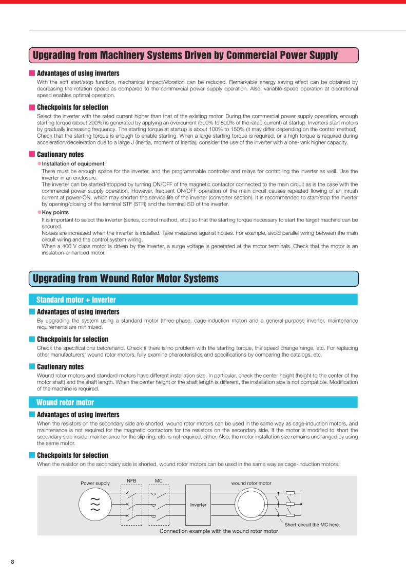
Advantages of using invertersWhen the resistors on the secondary side are shorted, wound rotor motors can be used in the same way as cage-induction motors, and maintenance is not required for the magnetic contactors for the resistors on the secondary side. If the motor is modified to short the secondary side inside, maintenance for the slip ring, etc. is not required, either. Also, the motor installation size remains unchanged by using the same motor.
Checkpoints for selectionWhen the resistor on the secondary side is shorted, wound rotor motors can be used in the same way as cage-induction motors.
Upgrading from Eddy Current Coupling Motor (AS Motor) Systems
Advantages of using invertersBy upgrading the system using a standard motor (three-phase, cage-induction motor) and a general-purpose inverter, maintenance requirements are minimized. Also, as a large loss is generated with the eddy current coupling motor, the energy saving effect can be achieved by upgrading the system.
Checkpoints for selectionCheck the specifications beforehand. Although the inverter-driven type system is advantageous in general, check if there is no problem with the maximum torque, etc. For replacing other manufacturers' eddy current coupling motors, fully examine characteristics and specifications by comparing the catalogs, etc.Because eddy current coupling motors are selected to cover the mechanical characteristics, it is not necessarily required to match the characteristics between the existing system and the replacement inverter system.In general, load characteristics (torque) of machinery are classified into the following three types. Compare the characteristics between the eddy current coupling motor and the inverter system, and select the inverter depending on the load characteristics type of the target machine.
●Constant torque characteristics (constant torque regardless of the running speed)Generally abrasive loads for driving conveyors, carriers, rolls in the process line, etc.
●Variable torque characteristics (The load torque changes proportionally against the square of the rotation speed.)Fluid loads for driving fans, pumps, blowers, etc.
●Constant output characteristics (The load torque increases as the running speed decreases. The product of the torque and the speed is constant.)Main shaft drive of machine tools, winding machines (center drive), etc.
Cautionary notes[Motor installation size]Eddy current coupling motors and standard motors have different installation size. In particular, check the center height (height to the center of the motor shaft) and the shaft length. When the center height or the shaft length is different, the installation size is not compatible. Modification of the machine is required.
[Unit installation compatibility]The external shape and dimensions differ between the AS unit and the inverter. Check the outline dimension drawings.
Upgrading from Direct Current Motor Systems
Advantages of using invertersBy upgrading the system using a standard motor (three-phase, cage-induction motor) and a general-purpose inverter, maintenance requirements are minimized.
Checkpoints for selectionCheck the specifications beforehand. Check if there is no problem with the maximum speed, the speed response, the speed change range, etc. For replacing other manufacturers' direct current motors, fully examine characteristics and specifications by comparing the catalogs, etc.We recommend the use of the FR-A800 series inverter (with the plug-in option FR-A8AP) to obtain satisfactory performance in the applications where sufficient torque is required in the low-speed range, the speed ratio is large, the speed accuracy or the response is important, or torque control is performed. When the performance requirement for the target machine is not so critical, general-purpose inverters without vector control may be used for replacement.
Cautionary notes[Motor installation size]Direct current motors and standard motors have different installation size. In particular, check the center height (height to the center of the motor shaft) and the shaft length. When the center height or the shaft length is different, the installation size is not compatible. Modification of the machine is required.
[Unit installation compatibility]The external shape and dimensions differ between the conventional DC amplifier and the inverter. Check the outline dimension drawings.
Power supply NFB MC wound rotor motor
Connection example with the wound rotor motor
Inverter
Short-circuit the MC here.←
Comparison of the continuous output torque
3.7 kW or lower
5.5 kW or lower
100
0 100 300 600 900 1200 1500 1800
Speed (r/min)
AS motorAS motor
Driven by inverter, 6-poleDriven by inverter, 6-pole
Driven by inverter, 4-poleDriven by inverter, 4-pole
100
0 100 300 600 900 1200 1500 1650 1800
Speed (r/min)
AS motorAS motor
Driven by inverter, 6-poleDriven by inverter, 6-pole
Driven by inverter, 4-poleDriven by inverter, 4-pole
Standard motor + Inverter
Wound rotor motor
Con
tinuo
us o
utpu
t tor
que
(%)
Con
tinuo
us o
utpu
t tor
que
(%)
When the continuous output of the AS motor is supposed as 100% (60 Hz reference). With the standard torque boost setting of the inverter.

INVERTER
9
Upgrading from Machinery Systems Driven by Commercial Power Supply
Advantages of using invertersWith the soft start/stop function, mechanical impact/vibration can be reduced. Remarkable energy saving effect can be obtained by decreasing the rotation speed as compared to the commercial power supply operation. Also, variable-speed operation at discretional speed enables optimal operation.
Checkpoints for selectionSelect the inverter with the rated current higher than that of the existing motor. During the commercial power supply operation, enough starting torque (about 200%) is generated by applying an overcurrent (500% to 800% of the rated current) at startup. Inverters start motors by gradually increasing frequency. The starting torque at startup is about 100% to 150% (it may differ depending on the control method). Check that the starting torque is enough to enable starting. When a large starting torque is required, or a high torque is required during acceleration/deceleration due to a large J (inertia, moment of inertia), consider the use of the inverter with a one-rank higher capacity.
Cautionary notes●Installation of equipment
There must be enough space for the inverter, and the programmable controller and relays for controlling the inverter as well. Use the inverter in an enclosure.The inverter can be started/stopped by turning ON/OFF of the magnetic contactor connected to the main circuit as is the case with the commercial power supply operation. However, frequent ON/OFF operation of the main circuit causes repeated flowing of an inrush current at power-ON, which may shorten the service life of the inverter (converter section). It is recommended to start/stop the inverter by opening/closing of the terminal STF (STR) and the terminal SD of the inverter.
●Key pointsIt is important to select the inverter (series, control method, etc.) so that the starting torque necessary to start the target machine can be secured.Noises are increased when the inverter is installed. Take measures against noises. For example, avoid parallel wiring between the main circuit wiring and the control system wiring.When a 400 V class motor is driven by the inverter, a surge voltage is generated at the motor terminals. Check that the motor is an insulation-enhanced motor.
Upgrading from Wound Rotor Motor Systems
Advantages of using invertersBy upgrading the system using a standard motor (three-phase, cage-induction motor) and a general-purpose inverter, maintenance requirements are minimized.
Checkpoints for selectionCheck the specifications beforehand. Check if there is no problem with the starting torque, the speed change range, etc. For replacing other manufacturers' wound rotor motors, fully examine characteristics and specifications by comparing the catalogs, etc.
Cautionary notesWound rotor motors and standard motors have different installation size. In particular, check the center height (height to the center of the motor shaft) and the shaft length. When the center height or the shaft length is different, the installation size is not compatible. Modification of the machine is required.
Advantages of using invertersWhen the resistors on the secondary side are shorted, wound rotor motors can be used in the same way as cage-induction motors, and maintenance is not required for the magnetic contactors for the resistors on the secondary side. If the motor is modified to short the secondary side inside, maintenance for the slip ring, etc. is not required, either. Also, the motor installation size remains unchanged by using the same motor.
Checkpoints for selectionWhen the resistor on the secondary side is shorted, wound rotor motors can be used in the same way as cage-induction motors.
Upgrading from Eddy Current Coupling Motor (AS Motor) Systems
Advantages of using invertersBy upgrading the system using a standard motor (three-phase, cage-induction motor) and a general-purpose inverter, maintenance requirements are minimized. Also, as a large loss is generated with the eddy current coupling motor, the energy saving effect can be achieved by upgrading the system.
Checkpoints for selectionCheck the specifications beforehand. Although the inverter-driven type system is advantageous in general, check if there is no problem with the maximum torque, etc. For replacing other manufacturers' eddy current coupling motors, fully examine characteristics and specifications by comparing the catalogs, etc.Because eddy current coupling motors are selected to cover the mechanical characteristics, it is not necessarily required to match the characteristics between the existing system and the replacement inverter system.In general, load characteristics (torque) of machinery are classified into the following three types. Compare the characteristics between the eddy current coupling motor and the inverter system, and select the inverter depending on the load characteristics type of the target machine.
●Constant torque characteristics (constant torque regardless of the running speed)Generally abrasive loads for driving conveyors, carriers, rolls in the process line, etc.
●Variable torque characteristics (The load torque changes proportionally against the square of the rotation speed.)Fluid loads for driving fans, pumps, blowers, etc.
●Constant output characteristics (The load torque increases as the running speed decreases. The product of the torque and the speed is constant.)Main shaft drive of machine tools, winding machines (center drive), etc.
Cautionary notes[Motor installation size]Eddy current coupling motors and standard motors have different installation size. In particular, check the center height (height to the center of the motor shaft) and the shaft length. When the center height or the shaft length is different, the installation size is not compatible. Modification of the machine is required.
[Unit installation compatibility]The external shape and dimensions differ between the AS unit and the inverter. Check the outline dimension drawings.
Upgrading from Direct Current Motor Systems
Advantages of using invertersBy upgrading the system using a standard motor (three-phase, cage-induction motor) and a general-purpose inverter, maintenance requirements are minimized.
Checkpoints for selectionCheck the specifications beforehand. Check if there is no problem with the maximum speed, the speed response, the speed change range, etc. For replacing other manufacturers' direct current motors, fully examine characteristics and specifications by comparing the catalogs, etc.We recommend the use of the FR-A800 series inverter (with the plug-in option FR-A8AP) to obtain satisfactory performance in the applications where sufficient torque is required in the low-speed range, the speed ratio is large, the speed accuracy or the response is important, or torque control is performed. When the performance requirement for the target machine is not so critical, general-purpose inverters without vector control may be used for replacement.
Cautionary notes[Motor installation size]Direct current motors and standard motors have different installation size. In particular, check the center height (height to the center of the motor shaft) and the shaft length. When the center height or the shaft length is different, the installation size is not compatible. Modification of the machine is required.
[Unit installation compatibility]The external shape and dimensions differ between the conventional DC amplifier and the inverter. Check the outline dimension drawings.
Power supply NFB MC wound rotor motor
Connection example with the wound rotor motor
Inverter
Short-circuit the MC here.←
Comparison of the continuous output torque
3.7 kW or lower
5.5 kW or lower
100
0 100 300 600 900 1200 1500 1800
Speed (r/min)
AS motorAS motor
Driven by inverter, 6-poleDriven by inverter, 6-pole
Driven by inverter, 4-poleDriven by inverter, 4-pole
100
0 100 300 600 900 1200 1500 1650 1800
Speed (r/min)
AS motorAS motor
Driven by inverter, 6-poleDriven by inverter, 6-pole
Driven by inverter, 4-poleDriven by inverter, 4-pole
Standard motor + Inverter
Wound rotor motor
Con
tinuo
us o
utpu
t tor
que
(%)
Con
tinuo
us o
utpu
t tor
que
(%)
When the continuous output of the AS motor is supposed as 100% (60 Hz reference). With the standard torque boost setting of the inverter.

INVERTER
10
Further Energy Saving Operation with Premium High-efficiency IPM MotorMitsubishi Inverter Family ProductsHigh Performance and High Functionality Inverter
[Leading drive performance]●The enhanced Real sensorless vector control and
vector control achieves improved speed response and high-speed operation.
●The PM motor auto tuning funct ion enables operation of other manufacturers' permanent magnet (PM) motors.
[Security & safety]●Controls with safety funct ions can be easi ly
performed. (Safety stop function)●24 VDC control power input is equipped as standard.
The parameter setting and communication operation can be done without turning ON the main power.
●The operat ing status immediately before the protective function is activated can be stored with the trace function, facilitating the trouble analysis at a separate location by using a USB memory device and the inverter setup software (FR Configurator2).
FR-A800 Simple and Powerful Inverter
[Pursuing performance]●With Advanced magnetic flux vector control, the
top-level drive performance has been achieved among compact inver ters . More tenac ious operation is possible.(200% 0.5 Hz (3.7 K or lower) in the Advanced magnetic flux vector control setting)
[Easy to use (Outstanding operability and enhanced expandability)]●The non-slip setting dial with adaptive scroll speed
allows for quick jumps or precise increments based on turning speed.
●USB connection facilitates easy setting with FR Configurator from a personal computer.
[Compact and space-saving]●The installation size is the same as the conventional
models (FR-E500 series) for exchangeability.
FR-E700
Enhanced Next-Generation Energy-Saving Inverter
[Energy saving]●Advanced optimum excitation control, which has
been newly developed, provides a large starting torque while maintaining the motor efficiency under the conventional Optimum excitation control.
●The tun ing funct ion enables operat ion of other manufacturers' induction motors and PM motors, which increases the use in the energy saving applications.
[Functions ideal for fans and pumps]●The rating can be selected between the two types (LD
(light duty) or SLD (superlight duty)) depending on the load of the fan/pump to be used (multiple rating).
●The inverter can perform PID control of the motor operation and control the external equipment at the same time (PID multiple loops). The system cost can be reduced.
●By controlling the pumps connected in parallel (up to four pumps) by the PID control, water volume, etc. can be adjusted by one inverter (multi-pump function).
FR-F800
MM-EFS/MM-THE4 Series
Easy and Compact Inverter
[Higher reliability]●High reliability and safety have been achieved by
incorporating spring clamp terminals, the safety stop function, and the password function.
[Compact]●The installation size is the same as the conventional
models (FR-S500 series) for exchangeability.
[Pursuing performance]●General-purpose magnetic flux vector control
ensures reliable operation for applications that require high starting torque.(in the 150% 1 Hz General-purpose magnetic flux control sett ing, when the sl ip compensation function is enabled)
FR-D700
With a Filterpack
Inverter for Air Conditioning
[Suitable for both the general-purpose motor and the IPM motor]●Both the general-purpose motor and the IPM motor
can be operated. The general-purpose motor driving setting can be switched to IPM driving setting by only one setting.
[Reduction in the environmental loads]●A model with Filterpack as standard (FR-F7□
0PJ-□F) is available. A Filterpack contains a power factor improving DC reactor essential for air conditioning, a common mode choke (line noise filter), and a capacitive filter (radio noise filter) in one.
●Less wiring and smaller space achieved by using the Filterpack also enable compliance with the Harmonic Suppress ion Guide l ines and the Architectural Standard Specifications in Japan.
FR-F700PJ
Capacity table
What is an IPM motor?IPM stands for Interior Permanent Magnet.An IPM motor is a synchronous motor with permanent magnets embedded inside.
Why is an IPM motor so efficient?1) No current flows to the rotor (secondary side), and no secondary copper loss is generated.2) Magnetic flux is generated with permanent magnets, and less motor current is required.3) Embedded magnets provide reluctance torque, and the reluctance torque can be applied.
Simple and reliable transition from general-purpose motors (compatible installation size)●The frame number (size) is the same as that of the Mitsubishi
general-purpose motors, "SF-JR/SF-HR series (55 kW or lower) and SF-TH series (75 kW or higher)". The compatible installation size enables easy replacement from the general-purpose motors.
Energy saving with speed control●The consumed power of a variable-torque load, such as fans,
pumps, and blowers, is proportional to the cube of its rotation speed. ●This means that controlling
the rotation speed to adjust the air volume can lead to energy savings.
*1: Rated motor output is 100%.
*2: As of June 2016
SF-JR 3.7kW MM-EFS371M4
Energy saving by driving an IPM motor●High efficiency with an IPM motor
Same
Efficiency classIEC 60034-30
Mitsubishi motor efficiency
general-purpose motor IPM motor
IE4 (super premium efficiency) *3
IE3 (premium efficiency)
IE2 (high efficiency)
IE1 (standard efficiency)
Below the class
Superline series(SF-JR)
Premium high-efficiency IPM(MM-EFS, MM-THE4)
Superline premiumseries (SF-PR)
Superlineeco series (SF-HR)
*3: The details of IE4 are specified in IEC 60034-31.
IE4-equivalent efficiency level●With the premium high-efficiency IPM motor MM-EFS series
and MM-THE4 series, the efficiency equivalent to IE4 (super premium efficiency), the highest-class efficiency standard, is obtained.*2
65
70
75
80
85
90
95
100
[Comparison of efficiency]
Motor capacity (kW)[Compared to our conventional product]
0.75 1.
52.
23.
75.
57.
5 11 1518
.5 22 30 37 45 55 75 90 110
132
160
SF-JR/SF-TH
SF-PR/SF-THE3
MM-EFS/MM-THE4
FR-A820-□KFR-A840-□KFR-A842-□K*2
FR-A846-□K*3
FR-F820-□KFR-F840-□KFR-F842-□K*2
FR-F720PJ-□K(F)*7
FR-F740PJ-□K(F)*7
FR-D720-□KFR-D740-□KFR-D720S-□KFR-D710W-□K
FR-E710W-□KFR-E720S-□K*4FR-E740-□K*4*5*6FR-E720-□K*4*5*6
Voltage class
Three-phase 200 V
Three-phase 400 V
Single-phase 200 V (Note)
Single-phase 100 V (Note)
(Note) The output is three-phase 200 V.
ModelInverter capacity
0.1 0.2 0.4 0.75 1.5 2.2 3.7 5.5 7.5 11 15 18.5 22 3730 45 55 75 90 110 132 160 185 220 250 280 315 355 400 450 500 560
IP55
*1: The motor can also be used for applications which required the rated speed of 1800 r/min.*2: The outdoor type and class B are semi-standard models.
●: Released model, -: Not applicable
Rotation speed (r/min)
Rotation speed (r/min)
0150
500 1800
0
140
120
100
60
80
40
20
300 900 1200 15002100
2250
80 %66.7 %
Continuous operation torqueContinuous operation torque
Maximum short-time (60 s) torqueMaximum short-time (60 s) torque
M M - T H E 4[75 kW or higher]
●The motor can be used for applications which required the rated speed of 1500 r/min and 1800 r/min.●For dedicated motors such as the outdoor type, the long-axis type, the flange type, the waterproof outdoor type, and the corrosion proof type, contact your sales representative.
●Premium high-efficiency IPM motor (MM-EFS/MM-THE4 series)
●The IPM motor, with permanent magnets embedded in the rotor, achieves even higher efficiency as compared to the SF-PR/SF-THE3.
20
40
60
120
Air volume (%)40 60 80 100
0
80
100Damper control
SF-PR/SF-THE3driven by inverter
[Example of blower operation characteristic]
MM-EFS/MM-THE4driven by inverter
SF-JR/SF-THdriven by inverter
[Compared to our conventional product]
*1*1
*1: ND rated capacity for the FR-A800 series, and LD rated capacity for the FR-F800 series.*2: Separated converter type. Always install the converter unit (FR-CC2). (Not required when
a high power factor converter (FR-HC2) is used.)*3: IP55 compatible model.*4: The safety stop function model is indicated with SC.
*5: The FL remote communication function model is indicated with NF.*6: The CC-Link communication function model is indicated with NC.*7: Filterpack (FR-BFP2) is enclosed for the inverter with Filterpack ("F" at the end of its
model names marked on the packaging box.)
Effi
cien
cyH
igh
Low
Con
sum
ed p
ower
(%) *
1To
tal e
ffici
ency
(%)
Torq
ue (%
)To
rque
(%)
Notes●The IPM motor MM-EFS/MM-THE4 series cannot be driven by the commercial power supply.●For IPM motors, the total wiring length is 100 m maximum.●Only one IPM motor can be connected to an inverter.●For belt drive application of the 11 kW or higher motor with the 1500 r/min specification, use a dedicated motor.
Motor model
200 V class
400 V class
200 V class400 V class
MM-EFS□1MMM-EFS□1M-S10MM-EFS□3MM-EFS□1M4MM-EFS□1M4-S10MM-EFS□34
MM-THE4
Rated output (kW)
●-
●●-
●-
-
●-
●●-
●-
-
●-
●●-
●-
-
●-
●●-
●-
-
●●●●●●-
-
●●●●●●-
-
●●-
●●-
-
-
●●-
●●-
-
-
●●-
●●-
-
-
●●-
●●-
-
-
●●-
●●-
-
-
●-
●●-
●-
-
●-
●●-
●-
-
●●-
●●-
-
-
-
-
-
-
-
-
●●
-
-
-
-
-
-
-
●
-
-
-
-
-
-
-
●
-
-
-
-
-
-
-
●
-
-
-
-
-
-
-
●
2.222
3.737
5.555
7.575
1111K
1515K
18.518K
2222K
3030K
3737K
4545K
75-
90-
110-
132-
160-
0.757
1.515
5555K
●MM-EFS 3000 r/min
0300 4000
30001800600 4200
0
140
120
100
60
80
40
20
Continuous operation torque
Maximum short-time (60 s) torque
●MM-EFS 1500 r/min 83.3%100% reference torque at 1800 r/min rating
None4
200 V400 V
SymbolVoltageclass
NoneQ
StandardClass B
Symbol
NoneP1
StandardOutdoor type
Symbol
1M3
1500 r/min3000 r/min
Symbol
Refer to the motormodel in the tablebelow.
Refer to the ratedoutput in the tablebelow.
Symbol Output
[55 kW or lower]
None-S10
StandardBelt drive model
Symbol Dedicated specification
M M - E F S 7 1 M 4
Rated rotationspeed *1*1 *2*2 *2*2
Specifications Specifications

INVERTER
11
Further Energy Saving Operation with Premium High-efficiency IPM MotorMitsubishi Inverter Family ProductsHigh Performance and High Functionality Inverter
[Leading drive performance]●The enhanced Real sensorless vector control and
vector control achieves improved speed response and high-speed operation.
●The PM motor auto tuning funct ion enables operation of other manufacturers' permanent magnet (PM) motors.
[Security & safety]●Controls with safety funct ions can be easi ly
performed. (Safety stop function)●24 VDC control power input is equipped as standard.
The parameter setting and communication operation can be done without turning ON the main power.
●The operat ing status immediately before the protective function is activated can be stored with the trace function, facilitating the trouble analysis at a separate location by using a USB memory device and the inverter setup software (FR Configurator2).
FR-A800 Simple and Powerful Inverter
[Pursuing performance]●With Advanced magnetic flux vector control, the
top-level drive performance has been achieved among compact inver ters . More tenac ious operation is possible.(200% 0.5 Hz (3.7 K or lower) in the Advanced magnetic flux vector control setting)
[Easy to use (Outstanding operability and enhanced expandability)]●The non-slip setting dial with adaptive scroll speed
allows for quick jumps or precise increments based on turning speed.
●USB connection facilitates easy setting with FR Configurator from a personal computer.
[Compact and space-saving]●The installation size is the same as the conventional
models (FR-E500 series) for exchangeability.
FR-E700
Enhanced Next-Generation Energy-Saving Inverter
[Energy saving]●Advanced optimum excitation control, which has
been newly developed, provides a large starting torque while maintaining the motor efficiency under the conventional Optimum excitation control.
●The tun ing funct ion enables operat ion of other manufacturers' induction motors and PM motors, which increases the use in the energy saving applications.
[Functions ideal for fans and pumps]●The rating can be selected between the two types (LD
(light duty) or SLD (superlight duty)) depending on the load of the fan/pump to be used (multiple rating).
●The inverter can perform PID control of the motor operation and control the external equipment at the same time (PID multiple loops). The system cost can be reduced.
●By controlling the pumps connected in parallel (up to four pumps) by the PID control, water volume, etc. can be adjusted by one inverter (multi-pump function).
FR-F800
MM-EFS/MM-THE4 Series
Easy and Compact Inverter
[Higher reliability]●High reliability and safety have been achieved by
incorporating spring clamp terminals, the safety stop function, and the password function.
[Compact]●The installation size is the same as the conventional
models (FR-S500 series) for exchangeability.
[Pursuing performance]●General-purpose magnetic flux vector control
ensures reliable operation for applications that require high starting torque.(in the 150% 1 Hz General-purpose magnetic flux control sett ing, when the sl ip compensation function is enabled)
FR-D700
With a Filterpack
Inverter for Air Conditioning
[Suitable for both the general-purpose motor and the IPM motor]●Both the general-purpose motor and the IPM motor
can be operated. The general-purpose motor driving setting can be switched to IPM driving setting by only one setting.
[Reduction in the environmental loads]●A model with Filterpack as standard (FR-F7□
0PJ-□F) is available. A Filterpack contains a power factor improving DC reactor essential for air conditioning, a common mode choke (line noise filter), and a capacitive filter (radio noise filter) in one.
●Less wiring and smaller space achieved by using the Filterpack also enable compliance with the Harmonic Suppress ion Guide l ines and the Architectural Standard Specifications in Japan.
FR-F700PJ
Capacity table
What is an IPM motor?IPM stands for Interior Permanent Magnet.An IPM motor is a synchronous motor with permanent magnets embedded inside.
Why is an IPM motor so efficient?1) No current flows to the rotor (secondary side), and no secondary copper loss is generated.2) Magnetic flux is generated with permanent magnets, and less motor current is required.3) Embedded magnets provide reluctance torque, and the reluctance torque can be applied.
Simple and reliable transition from general-purpose motors (compatible installation size)●The frame number (size) is the same as that of the Mitsubishi
general-purpose motors, "SF-JR/SF-HR series (55 kW or lower) and SF-TH series (75 kW or higher)". The compatible installation size enables easy replacement from the general-purpose motors.
Energy saving with speed control●The consumed power of a variable-torque load, such as fans,
pumps, and blowers, is proportional to the cube of its rotation speed. ●This means that controlling
the rotation speed to adjust the air volume can lead to energy savings.
*1: Rated motor output is 100%.
*2: As of June 2016
SF-JR 3.7kW MM-EFS371M4
Energy saving by driving an IPM motor●High efficiency with an IPM motor
Same
Efficiency classIEC 60034-30
Mitsubishi motor efficiency
general-purpose motor IPM motor
IE4 (super premium efficiency) *3
IE3 (premium efficiency)
IE2 (high efficiency)
IE1 (standard efficiency)
Below the class
Superline series(SF-JR)
Premium high-efficiency IPM(MM-EFS, MM-THE4)
Superline premiumseries (SF-PR)
Superlineeco series (SF-HR)
*3: The details of IE4 are specified in IEC 60034-31.
IE4-equivalent efficiency level●With the premium high-efficiency IPM motor MM-EFS series
and MM-THE4 series, the efficiency equivalent to IE4 (super premium efficiency), the highest-class efficiency standard, is obtained.*2
65
70
75
80
85
90
95
100
[Comparison of efficiency]
Motor capacity (kW)[Compared to our conventional product]
0.75 1.
52.
23.
75.
57.
5 11 1518
.5 22 30 37 45 55 75 90 110
132
160
SF-JR/SF-TH
SF-PR/SF-THE3
MM-EFS/MM-THE4
FR-A820-□KFR-A840-□KFR-A842-□K*2
FR-A846-□K*3
FR-F820-□KFR-F840-□KFR-F842-□K*2
FR-F720PJ-□K(F)*7
FR-F740PJ-□K(F)*7
FR-D720-□KFR-D740-□KFR-D720S-□KFR-D710W-□K
FR-E710W-□KFR-E720S-□K*4FR-E740-□K*4*5*6FR-E720-□K*4*5*6
Voltage class
Three-phase 200 V
Three-phase 400 V
Single-phase 200 V (Note)
Single-phase 100 V (Note)
(Note) The output is three-phase 200 V.
ModelInverter capacity
0.1 0.2 0.4 0.75 1.5 2.2 3.7 5.5 7.5 11 15 18.5 22 3730 45 55 75 90 110 132 160 185 220 250 280 315 355 400 450 500 560
IP55
*1: The motor can also be used for applications which required the rated speed of 1800 r/min.*2: The outdoor type and class B are semi-standard models.
●: Released model, -: Not applicable
Rotation speed (r/min)
Rotation speed (r/min)
0150
500 1800
0
140
120
100
60
80
40
20
300 900 1200 15002100
2250
80 %66.7 %
Continuous operation torqueContinuous operation torque
Maximum short-time (60 s) torqueMaximum short-time (60 s) torque
M M - T H E 4[75 kW or higher]
●The motor can be used for applications which required the rated speed of 1500 r/min and 1800 r/min.●For dedicated motors such as the outdoor type, the long-axis type, the flange type, the waterproof outdoor type, and the corrosion proof type, contact your sales representative.
●Premium high-efficiency IPM motor (MM-EFS/MM-THE4 series)
●The IPM motor, with permanent magnets embedded in the rotor, achieves even higher efficiency as compared to the SF-PR/SF-THE3.
20
40
60
120
Air volume (%)40 60 80 100
0
80
100Damper control
SF-PR/SF-THE3driven by inverter
[Example of blower operation characteristic]
MM-EFS/MM-THE4driven by inverter
SF-JR/SF-THdriven by inverter
[Compared to our conventional product]
*1*1
*1: ND rated capacity for the FR-A800 series, and LD rated capacity for the FR-F800 series.*2: Separated converter type. Always install the converter unit (FR-CC2). (Not required when
a high power factor converter (FR-HC2) is used.)*3: IP55 compatible model.*4: The safety stop function model is indicated with SC.
*5: The FL remote communication function model is indicated with NF.*6: The CC-Link communication function model is indicated with NC.*7: Filterpack (FR-BFP2) is enclosed for the inverter with Filterpack ("F" at the end of its
model names marked on the packaging box.)
Effi
cien
cyH
igh
Low
Con
sum
ed p
ower
(%) *
1To
tal e
ffici
ency
(%)
Torq
ue (%
)To
rque
(%)
Notes●The IPM motor MM-EFS/MM-THE4 series cannot be driven by the commercial power supply.●For IPM motors, the total wiring length is 100 m maximum.●Only one IPM motor can be connected to an inverter.●For belt drive application of the 11 kW or higher motor with the 1500 r/min specification, use a dedicated motor.
Motor model
200 V class
400 V class
200 V class400 V class
MM-EFS□1MMM-EFS□1M-S10MM-EFS□3MM-EFS□1M4MM-EFS□1M4-S10MM-EFS□34
MM-THE4
Rated output (kW)
●-
●●-
●-
-
●-
●●-
●-
-
●-
●●-
●-
-
●-
●●-
●-
-
●●●●●●-
-
●●●●●●-
-
●●-
●●-
-
-
●●-
●●-
-
-
●●-
●●-
-
-
●●-
●●-
-
-
●●-
●●-
-
-
●-
●●-
●-
-
●-
●●-
●-
-
●●-
●●-
-
-
-
-
-
-
-
-
●●
-
-
-
-
-
-
-
●
-
-
-
-
-
-
-
●
-
-
-
-
-
-
-
●
-
-
-
-
-
-
-
●
2.222
3.737
5.555
7.575
1111K
1515K
18.518K
2222K
3030K
3737K
4545K
75-
90-
110-
132-
160-
0.757
1.515
5555K
●MM-EFS 3000 r/min
0300 4000
30001800600 4200
0
140
120
100
60
80
40
20
Continuous operation torque
Maximum short-time (60 s) torque
●MM-EFS 1500 r/min 83.3%100% reference torque at 1800 r/min rating
None4
200 V400 V
SymbolVoltageclass
NoneQ
StandardClass B
Symbol
NoneP1
StandardOutdoor type
Symbol
1M3
1500 r/min3000 r/min
Symbol
Refer to the motormodel in the tablebelow.
Refer to the ratedoutput in the tablebelow.
Symbol Output
[55 kW or lower]
None-S10
StandardBelt drive model
Symbol Dedicated specification
M M - E F S 7 1 M 4
Rated rotationspeed *1*1 *2*2 *2*2
Specifications Specifications

INVERTER
12
Points to be checkedBefore upgrading, check the following items.
Mitsubishi Electric System & Service Co., Ltd. provide support for maintenance and inspection of inverters, engineering works for upgrading to the latest models, and total system upgrade so that our customers can continue using their equipment with confidence for a long time.
Check item ProblemInverter Peripheral devices
Remedy
Solutions for Maintenance/Inspection of Inverters, Upgrading,and Total System Configuration
System upgrade proposals
Renewal engineering work procedure
Inst
alla
tion
Per
form
ance
leak
age
curr
ent
Oth
ers
Installation environment
Wiring
Power supply capacity
Low speed torque shortage
Motor noise
Vibration
Unnecessary operation
Efficiency
Power factor
Surge voltage
Oil mist, fluff, dust, dirt, etc. are floating in the air.
When the inverter is installed in the enclosure, the temperature inside the enclosure reaches or exceeds 40°C.
A metallic noise is generated from the motor due to the PWM carrier frequency.
The motor vibration increases by PWM switching, and resonance with the machine occurs.
A leakage current causes an unnecessary operation of the earth leakage circuit breakers or the earth leakage relays.
Because of the rectifier circuit with a smoothing capacitor, the effective value of the input current is large.
Losses are generated in the inverter.
The inverter circuit is damaged when a voltage is applied to the secondary side output terminal of the inverter.A different device is misconnected to the connection terminal for the dedicated option.The frequency setting power supply terminal (10) and the common terminal (5) are shorted due to incorrect wiring.
When the inverter is connected near a large-capacity power transformer (with a capacity of 1000 kVA or more with the wiring length shorter than 10 m) or when a power factor correction capacitor is to be switched over, an excessive peak current may flow in the power input circuit, damaging the inverter.
Noise is generated by PWM switching. The noise increases when the carrier frequency is increased for the low acoustic noise operation.Signal cables are adversely affected by the electromagnetic noise of the inverter.(Incorrect input, etc.)
When a thyristor converter or a vacuum contactor exist in the same power supply system, a surge voltage is generated in the power line, and the inverter malfunction occurs.
The excitation voltage decreases due to a voltage drop through the motor primary coil and the wiring resistance. The influence is larger during the low-speed operation.
A leakage current flows doe to the stray capacitance between lines, and the thermal relay is activated.A leakage current increases when the carrier frequency is increased for the low acoustic noise operation.
Due to a large inrush current from the rectifier circuit with a smoothing capacitor, the input voltage waveform is distorted. Suppression of the outgoing current according to the guideline is required.
With the long wiring length, the motor terminal voltage increases by PWM switching and insulation of the 400 V motor is degraded.
Noise
Power supply harmonics
Upgrading existing inverters
Replacement of conventional models with the latest models[Merits]●Prevention of opportunity loss due to equipment stop by an
accidental failure●Cooling fan change without removing the main circuit wiring●Reduction in the maintenance cost●Energy saving effect with the increased motor efficiency by
selecting the Optimum excitation control mode (especially for fans and pumps)
Energy saving with inverters
Change from the commercial power supply operation with damper control to the inverter control for loads such as blowers and pumps[Merits]●Power saving by the energy saving effect●More comfortable operation by very fine rotation speed
control●Mechanical design available regardless of the power supply
frequency (50/60 Hz)●Motor cooling fan wind noise reduced by low-speed operation
Replacing variable speed motors
Replacement of eddy current coupling motors (AS motors), direct current (DC) motors, etc. with the general-purpose inverters with induction motors[Merits]●Easy maintenance (no need to check or change the brush)●Reduction in the power supply capacity●Changeable to the robust "cage-induction motor"
Total system support
Total support for customers from maintenance/inspection of inverters and high-voltage circuit breakers to engineering work for upgrading systems with control panels, programmable controllers, servos, etc.[Menu]●Design/manufacturing of control panels for upgrading●Design / engineering work / adjustment for replacing the
discontinued AC servo models●Design / engineering work / adjustment for upgrading the A
(large type) series programmable controllers to the Q series●Total system proposal for equipment including monitoring
Proposal
Consultation ● Confirmation of details
Estimation ● Equipment selection and estimation
Order ● Engineering work scheduling
Equipment procurement ● Procurement of products and components
System design/manufacturing ● Hardware design/manufacturing (as required)● Software design/manufacturing (as required)
On-site engineering work ● Equipment replacement and installation / wiring change* Intercompatibility attachments are available for shortening the installation work period.
On-site adjustment ● Parameter setting and operation check* We request those who are familiar with specifications and handling of the equipment will be present.
Delivery
Field investigation ● Installation condition check for the target equipment and the optional equipment
● Check for the installation space available inside the enclosure, wiring, etc.
● Check for details of parameter settings● Check for operation specifications
* We ask for cooperation from those who are familiar with specifications and handling of the equipment.
: Use totally enclosed structure models.
: To be contained in the totally enclosed enclosure.
: Install heat pipes.
: Provide a separate power supply system.
: Increase the mechanical rigidity.
: Shorten the wiring length.
: Active filter
: Active filter
: Insulation-enhanced motor
: Shorten the wiring length.
: Protrude the heatsink out of the enclosure (the attachment is required).
: Sine wave filter*1
: Avoid resonance points by changing the carrier frequency or using the frequency jump function.
: Change the wiring route, or install a noise filter.Use twisted pair cables for signal cables.
: Decrease carrier frequency. Use the electronic thermal O/L relay function.
: Use the earth leakage circuit breaker designed for harmonics and surge suppression.
: High power factor converter
: 12-phase rectifier*2
: Power factor improving reactor
: High power factor converter
: Power factor improving reactor
: Surge voltage suppression filter
: Sine wave filter*1
: Install a power factor improving reactor.
: Decrease carrier frequency.
: Decrease carrier frequency.
: Install a power factor improving reactor.
: Change the control method.
: Perform a sequence check.
: Use a high-carrier frequency, or select the Soft-PWM control at a low-carrier frequency.
: Sine wave filter*1
: Cool the inside of the enclosure.
Effect: : Solved. : Largely improved. : Improved, but not enough. : Difficult to remedy.*1: It can be used for the operation of a 75K or higher inverter or a 75 kW or higher motor under V/F control.*2: It can be used for the converter unit (FR-CC2).

INVERTER
13
Points to be checkedBefore upgrading, check the following items.
Mitsubishi Electric System & Service Co., Ltd. provide support for maintenance and inspection of inverters, engineering works for upgrading to the latest models, and total system upgrade so that our customers can continue using their equipment with confidence for a long time.
Check item ProblemInverter Peripheral devices
Remedy
Solutions for Maintenance/Inspection of Inverters, Upgrading,and Total System Configuration
System upgrade proposals
Renewal engineering work procedure
Inst
alla
tion
Per
form
ance
leak
age
curr
ent
Oth
ers
Installation environment
Wiring
Power supply capacity
Low speed torque shortage
Motor noise
Vibration
Unnecessary operation
Efficiency
Power factor
Surge voltage
Oil mist, fluff, dust, dirt, etc. are floating in the air.
When the inverter is installed in the enclosure, the temperature inside the enclosure reaches or exceeds 40°C.
A metallic noise is generated from the motor due to the PWM carrier frequency.
The motor vibration increases by PWM switching, and resonance with the machine occurs.
A leakage current causes an unnecessary operation of the earth leakage circuit breakers or the earth leakage relays.
Because of the rectifier circuit with a smoothing capacitor, the effective value of the input current is large.
Losses are generated in the inverter.
The inverter circuit is damaged when a voltage is applied to the secondary side output terminal of the inverter.A different device is misconnected to the connection terminal for the dedicated option.The frequency setting power supply terminal (10) and the common terminal (5) are shorted due to incorrect wiring.
When the inverter is connected near a large-capacity power transformer (with a capacity of 1000 kVA or more with the wiring length shorter than 10 m) or when a power factor correction capacitor is to be switched over, an excessive peak current may flow in the power input circuit, damaging the inverter.
Noise is generated by PWM switching. The noise increases when the carrier frequency is increased for the low acoustic noise operation.Signal cables are adversely affected by the electromagnetic noise of the inverter.(Incorrect input, etc.)
When a thyristor converter or a vacuum contactor exist in the same power supply system, a surge voltage is generated in the power line, and the inverter malfunction occurs.
The excitation voltage decreases due to a voltage drop through the motor primary coil and the wiring resistance. The influence is larger during the low-speed operation.
A leakage current flows doe to the stray capacitance between lines, and the thermal relay is activated.A leakage current increases when the carrier frequency is increased for the low acoustic noise operation.
Due to a large inrush current from the rectifier circuit with a smoothing capacitor, the input voltage waveform is distorted. Suppression of the outgoing current according to the guideline is required.
With the long wiring length, the motor terminal voltage increases by PWM switching and insulation of the 400 V motor is degraded.
Noise
Power supply harmonics
Upgrading existing inverters
Replacement of conventional models with the latest models[Merits]●Prevention of opportunity loss due to equipment stop by an
accidental failure●Cooling fan change without removing the main circuit wiring●Reduction in the maintenance cost●Energy saving effect with the increased motor efficiency by
selecting the Optimum excitation control mode (especially for fans and pumps)
Energy saving with inverters
Change from the commercial power supply operation with damper control to the inverter control for loads such as blowers and pumps[Merits]●Power saving by the energy saving effect●More comfortable operation by very fine rotation speed
control●Mechanical design available regardless of the power supply
frequency (50/60 Hz)●Motor cooling fan wind noise reduced by low-speed operation
Replacing variable speed motors
Replacement of eddy current coupling motors (AS motors), direct current (DC) motors, etc. with the general-purpose inverters with induction motors[Merits]●Easy maintenance (no need to check or change the brush)●Reduction in the power supply capacity●Changeable to the robust "cage-induction motor"
Total system support
Total support for customers from maintenance/inspection of inverters and high-voltage circuit breakers to engineering work for upgrading systems with control panels, programmable controllers, servos, etc.[Menu]●Design/manufacturing of control panels for upgrading●Design / engineering work / adjustment for replacing the
discontinued AC servo models●Design / engineering work / adjustment for upgrading the A
(large type) series programmable controllers to the Q series●Total system proposal for equipment including monitoring
Proposal
Consultation ● Confirmation of details
Estimation ● Equipment selection and estimation
Order ● Engineering work scheduling
Equipment procurement ● Procurement of products and components
System design/manufacturing ● Hardware design/manufacturing (as required)● Software design/manufacturing (as required)
On-site engineering work ● Equipment replacement and installation / wiring change* Intercompatibility attachments are available for shortening the installation work period.
On-site adjustment ● Parameter setting and operation check* We request those who are familiar with specifications and handling of the equipment will be present.
Delivery
Field investigation ● Installation condition check for the target equipment and the optional equipment
● Check for the installation space available inside the enclosure, wiring, etc.
● Check for details of parameter settings● Check for operation specifications
* We ask for cooperation from those who are familiar with specifications and handling of the equipment.
: Use totally enclosed structure models.
: To be contained in the totally enclosed enclosure.
: Install heat pipes.
: Provide a separate power supply system.
: Increase the mechanical rigidity.
: Shorten the wiring length.
: Active filter
: Active filter
: Insulation-enhanced motor
: Shorten the wiring length.
: Protrude the heatsink out of the enclosure (the attachment is required).
: Sine wave filter*1
: Avoid resonance points by changing the carrier frequency or using the frequency jump function.
: Change the wiring route, or install a noise filter.Use twisted pair cables for signal cables.
: Decrease carrier frequency. Use the electronic thermal O/L relay function.
: Use the earth leakage circuit breaker designed for harmonics and surge suppression.
: High power factor converter
: 12-phase rectifier*2
: Power factor improving reactor
: High power factor converter
: Power factor improving reactor
: Surge voltage suppression filter
: Sine wave filter*1
: Install a power factor improving reactor.
: Decrease carrier frequency.
: Decrease carrier frequency.
: Install a power factor improving reactor.
: Change the control method.
: Perform a sequence check.
: Use a high-carrier frequency, or select the Soft-PWM control at a low-carrier frequency.
: Sine wave filter*1
: Cool the inside of the enclosure.
Effect: : Solved. : Largely improved. : Improved, but not enough. : Difficult to remedy.*1: It can be used for the operation of a 75K or higher inverter or a 75 kW or higher motor under V/F control.*2: It can be used for the converter unit (FR-CC2).
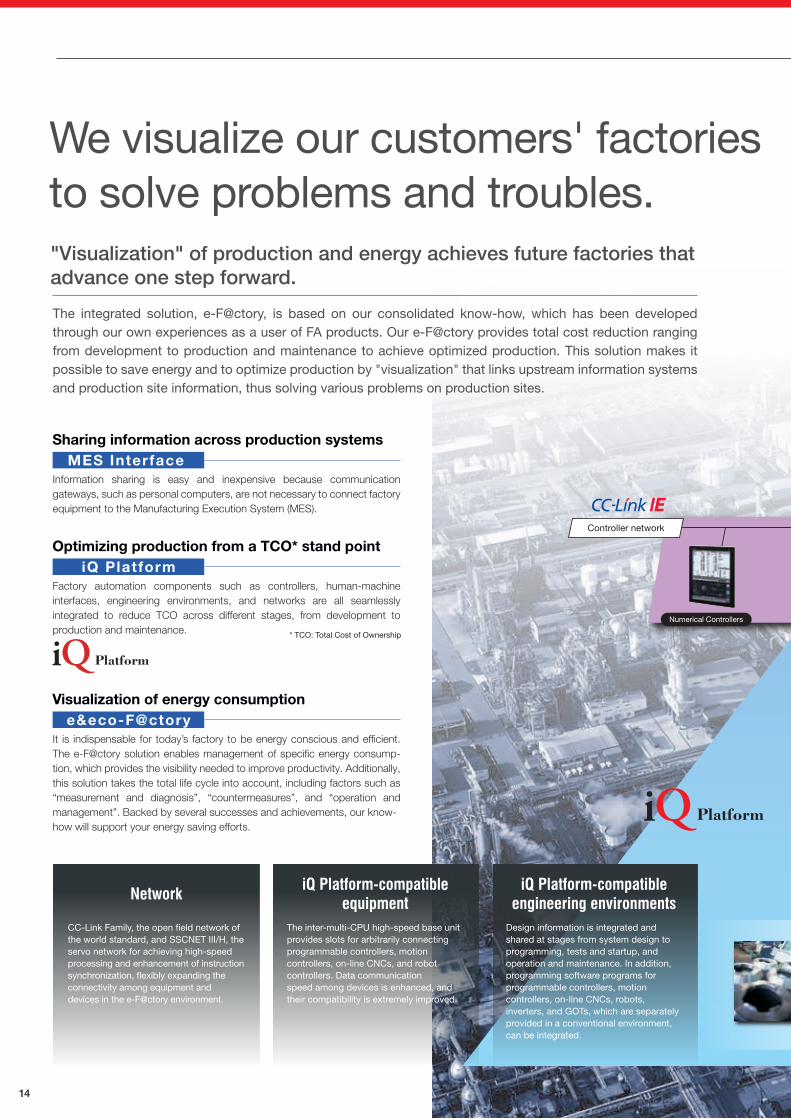
INVERTER
14
"Visualization"by information
linkage
Operation andplanning system
Information system
Production site
Robots Safety Controllers Motion Controllers
AC Servo
Programmable Controllers Electrical-Discharge Machines Laser Processing Machines
ERP
Ethernet
Products for achieving e-F@ctory
B/NET
Foolproofterminal
Mapping sensorterminal
Manufacturing execution systemMES
Information network
Safety field network Field network
Sensor network
Field network
Field network
Servo-network
Reduced wiring network
Safety remote I/O Energymeasurement unit
MDUbreaker
Electronic multi-indicatinginstrument
Remote I/O
ProgrammableControllers
Geared motor Robots
MES linkage functionMES linkage function
Diagnosis unit with MES Interface (MELQIC) HMI with MES Interface Programmable Controllers with MES Interface EcoServer III
Numerical Controllers
Controller network
CC-Link-AnyWireBitty Bridge
We visualize our customers' factories to solve problems and troubles."Visualization" of production and energy achieves future factories that advance one step forward.
The integrated solution, e-F@ctory, is based on our consolidated know-how, which has been developed through our own experiences as a user of FA products. Our e-F@ctory provides total cost reduction ranging from development to production and maintenance to achieve optimized production. This solution makes it possible to save energy and to optimize production by "visualization" that links upstream information systems and production site information, thus solving various problems on production sites.
Sharing information across production systems
Information sharing is easy and inexpensive because communication gateways, such as personal computers, are not necessary to connect factory equipment to the Manufacturing Execution System (MES).
* TCO: Total Cost of Ownership
MES Interface
Optimizing production from a TCO* stand point
Factory automation components such as controllers, human-machine interfaces, engineering environments, and networks are all seamlessly integrated to reduce TCO across different stages, from development to production and maintenance.
iQ Platform
Visualization of energy consumption
It is indispensable for today’s factory to be energy conscious and efficient. The e-F@ctory solution enables management of specific energy consump-tion, which provides the visibility needed to improve productivity. Additionally, this solution takes the total life cycle into account, including factors such as “measurement and diagnosis”, “countermeasures”, and “operation and management”. Backed by several successes and achievements, our know-how will support your energy saving efforts.
e&eco-F@ctory
iQ Platform-compatibleequipment
Design information is integrated and shared at stages from system design to programming, tests and startup, and operation and maintenance. In addition, programming software programs for programmable controllers, motion controllers, on-line CNCs, robots, inverters, and GOTs, which are separately provided in a conventional environment, can be integrated.
The inter-multi-CPU high-speed base unit provides slots for arbitrarily connecting programmable controllers, motion controllers, on-line CNCs, and robot controllers. Data communicationspeed among devices is enhanced, and their compatibility is extremely improved.
CC-Link Family, the open field network of the world standard, and SSCNET III/H, the servo network for achieving high-speed processing and enhancement of instruction synchronization, flexibly expanding the connectivity among equipment and devices in the e-F@ctory environment.
iQ Platform-compatibleengineering environmentsNetwork
Inverter
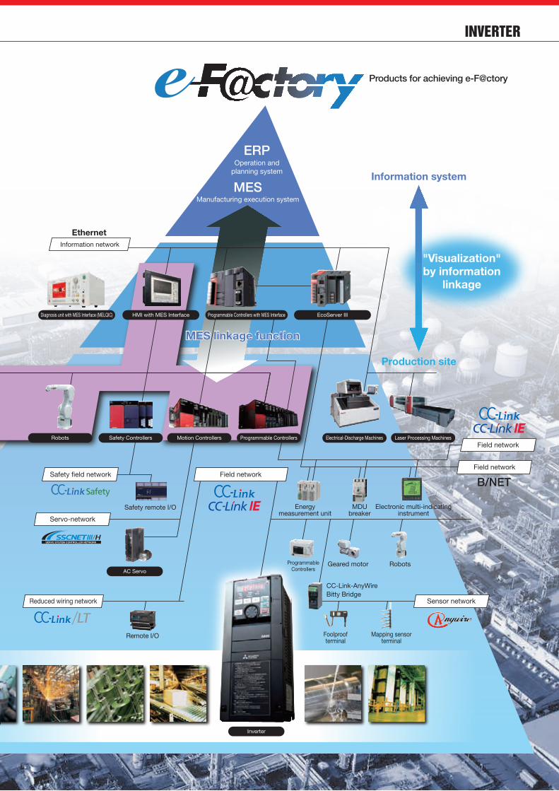
INVERTER
15
"Visualization"by information
linkage
Operation andplanning system
Information system
Production site
Robots Safety Controllers Motion Controllers
AC Servo
Programmable Controllers Electrical-Discharge Machines Laser Processing Machines
ERP
Ethernet
Products for achieving e-F@ctory
B/NET
Foolproofterminal
Mapping sensorterminal
Manufacturing execution systemMES
Information network
Safety field network Field network
Sensor network
Field network
Field network
Servo-network
Reduced wiring network
Safety remote I/O Energymeasurement unit
MDUbreaker
Electronic multi-indicatinginstrument
Remote I/O
ProgrammableControllers
Geared motor Robots
MES linkage functionMES linkage function
Diagnosis unit with MES Interface (MELQIC) HMI with MES Interface Programmable Controllers with MES Interface EcoServer III
Numerical Controllers
Controller network
CC-Link-AnyWireBitty Bridge
We visualize our customers' factories to solve problems and troubles."Visualization" of production and energy achieves future factories that advance one step forward.
The integrated solution, e-F@ctory, is based on our consolidated know-how, which has been developed through our own experiences as a user of FA products. Our e-F@ctory provides total cost reduction ranging from development to production and maintenance to achieve optimized production. This solution makes it possible to save energy and to optimize production by "visualization" that links upstream information systems and production site information, thus solving various problems on production sites.
Sharing information across production systems
Information sharing is easy and inexpensive because communication gateways, such as personal computers, are not necessary to connect factory equipment to the Manufacturing Execution System (MES).
* TCO: Total Cost of Ownership
MES Interface
Optimizing production from a TCO* stand point
Factory automation components such as controllers, human-machine interfaces, engineering environments, and networks are all seamlessly integrated to reduce TCO across different stages, from development to production and maintenance.
iQ Platform
Visualization of energy consumption
It is indispensable for today’s factory to be energy conscious and efficient. The e-F@ctory solution enables management of specific energy consump-tion, which provides the visibility needed to improve productivity. Additionally, this solution takes the total life cycle into account, including factors such as “measurement and diagnosis”, “countermeasures”, and “operation and management”. Backed by several successes and achievements, our know-how will support your energy saving efforts.
e&eco-F@ctory
iQ Platform-compatibleequipment
Design information is integrated and shared at stages from system design to programming, tests and startup, and operation and maintenance. In addition, programming software programs for programmable controllers, motion controllers, on-line CNCs, robots, inverters, and GOTs, which are separately provided in a conventional environment, can be integrated.
The inter-multi-CPU high-speed base unit provides slots for arbitrarily connecting programmable controllers, motion controllers, on-line CNCs, and robot controllers. Data communicationspeed among devices is enhanced, and their compatibility is extremely improved.
CC-Link Family, the open field network of the world standard, and SSCNET III/H, the servo network for achieving high-speed processing and enhancement of instruction synchronization, flexibly expanding the connectivity among equipment and devices in the e-F@ctory environment.
iQ Platform-compatibleengineering environmentsNetwork
Inverter

INVERTER
16
L : Mitsubishi Electric do Brasil Comércio e Serviços Ltda.
R : MELCO CNC do Brasil Comércio e Serviços S.A
Kraków, Poland
Mitsubishi Electric Europe B.V.Polish Branch(Europe FA Center)
Ratingen, Germany
Mitsubishi Electric Europe B.V.German Branch (Germany FA Center)
Istanbul, Turkey
Mitsubishi Electric TurkeyA.Ş Ümraniye Branch (Turkey FA Center)
Seoul, Korea
Mitsubishi Electric Automation Korea Co., Ltd. (Korea FA Center)
Pune, Gurgaon, Bangalore,Chennai, Ahmedabad, India
Mitsubishi Electric India Pvt. Ltd.
Hanoi,Ho Chi Minh, Vietnam
L : Mitsubishi Electric Vietnam Co., Ltd. Hanoi Branch
R : Mitsubishi Electric Vietnam Co., Ltd.
Taipei,Taichung, Taiwan
L : Setsuyo Enterprise Co., Ltd.
R : Mitsubishi Electric Taiwan Co.,Ltd.
Sao Paulo SP, Brazil
Mitsubishi Electric Factory Automation (Thailand) Co., Ltd. (Thai FA Center)
Bangkok, Thailand
Mitsubishi Electric Europe B.V. UK Branch (UK FA Center)
Mitsubishi Electric Europe B.V.Czech Branch (Czech Republic FA Center)
Mitsubishi Electric Asia Pte, Ltd. (ASEAN FA Center)
PT. Mitsubishi ElectricIndonesia Cikarang Office
(Indonesia FA Center)
Mitsubishi Electric Automation, Inc. (North America FA Center)
Mitsubishi ElectricAutomation, Inc. Mexico Branch(Mexico FA Center)
St.Petersburg, Russia
Mitsubishi Electric Europe B.V.Representative Office in St. Petersburg (Russia FA Center)
Nagoya, Japan
Hatfield, UK
Chicago IL, USAPraha, Czech Republic
Singapore Jakarta, Indonesia
Tlalnepantla De Baz, Mexico
FA Center Satellite (China) Mitsubishi Sales OfficesGlobal FA Center
Mechatronics Service Base (China) Production Facility Development Center
Shanghai
Dalian
Qingdao
Wuhang
Chengdu
Chongqing
Shenyang
FuzhouTaipei
Taichung
Xiangfan
Zhengzhou
Tianjin
Beijing
Guangzhou
Shenzhen
China (including Hong Kong District)
Global network for comprehensive support of customers' manufacturing.
Tianjin
Mitsubishi Automation (China) Ltd.Tianjin Office (Tianjin FA Center)
Beijing
Mitsubishi Automation (China) Ltd.Beijing Office (Beijing FA Center)
Guangzhou
Mitsubishi Electric Automation (China) Ltd. Guangzhou Office (Guangzhou FA Center)
Shanghai
Mitsubishi Automation (China) Ltd.(Shanghai FA Center)
Shanghai
Mitsubishi Electric Automation Solution Center
Service bases are established around the world to globally provide the same services as in Japan.
Overseas bases are opened one after another to support business expansion of our customers.
* Some includes distributorsAs of July 2014Overseas bases
Area Our overseas officesFA Center (Satellite)
Bases providingour products
Countries (Regions)
54
1
10
16
2
83
Changchun
6 (2)
4 (10)
13
4 (0)
0
27 (12)
11
13
21
14
1
60
146
171
79
130
3
529
EMEA
China
Asia
America
Others
Total
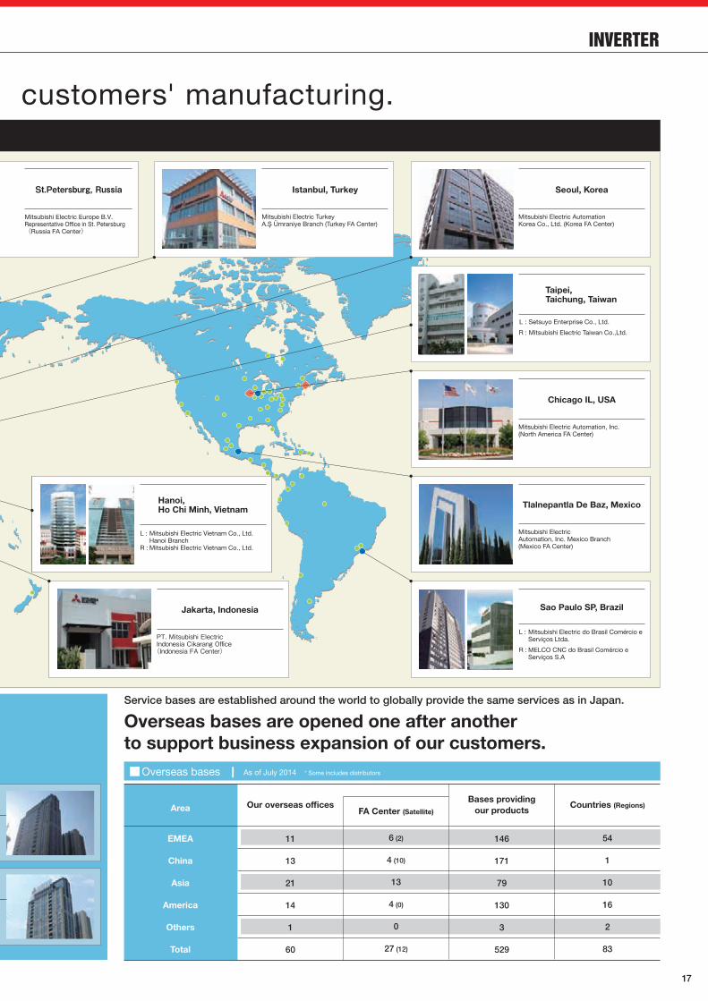
INVERTER
17
L : Mitsubishi Electric do Brasil Comércio e Serviços Ltda.
R : MELCO CNC do Brasil Comércio e Serviços S.A
Kraków, Poland
Mitsubishi Electric Europe B.V.Polish Branch(Europe FA Center)
Ratingen, Germany
Mitsubishi Electric Europe B.V.German Branch (Germany FA Center)
Istanbul, Turkey
Mitsubishi Electric TurkeyA.Ş Ümraniye Branch (Turkey FA Center)
Seoul, Korea
Mitsubishi Electric Automation Korea Co., Ltd. (Korea FA Center)
Pune, Gurgaon, Bangalore,Chennai, Ahmedabad, India
Mitsubishi Electric India Pvt. Ltd.
Hanoi,Ho Chi Minh, Vietnam
L : Mitsubishi Electric Vietnam Co., Ltd. Hanoi Branch
R : Mitsubishi Electric Vietnam Co., Ltd.
Taipei,Taichung, Taiwan
L : Setsuyo Enterprise Co., Ltd.
R : Mitsubishi Electric Taiwan Co.,Ltd.
Sao Paulo SP, Brazil
Mitsubishi Electric Factory Automation (Thailand) Co., Ltd. (Thai FA Center)
Bangkok, Thailand
Mitsubishi Electric Europe B.V. UK Branch (UK FA Center)
Mitsubishi Electric Europe B.V.Czech Branch (Czech Republic FA Center)
Mitsubishi Electric Asia Pte, Ltd. (ASEAN FA Center)
PT. Mitsubishi ElectricIndonesia Cikarang Office
(Indonesia FA Center)
Mitsubishi Electric Automation, Inc. (North America FA Center)
Mitsubishi ElectricAutomation, Inc. Mexico Branch(Mexico FA Center)
St.Petersburg, Russia
Mitsubishi Electric Europe B.V.Representative Office in St. Petersburg (Russia FA Center)
Nagoya, Japan
Hatfield, UK
Chicago IL, USAPraha, Czech Republic
Singapore Jakarta, Indonesia
Tlalnepantla De Baz, Mexico
FA Center Satellite (China) Mitsubishi Sales OfficesGlobal FA Center
Mechatronics Service Base (China) Production Facility Development Center
Shanghai
Dalian
Qingdao
Wuhang
Chengdu
Chongqing
Shenyang
FuzhouTaipei
Taichung
Xiangfan
Zhengzhou
Tianjin
Beijing
Guangzhou
Shenzhen
China (including Hong Kong District)
Global network for comprehensive support of customers' manufacturing.
Tianjin
Mitsubishi Automation (China) Ltd.Tianjin Office (Tianjin FA Center)
Beijing
Mitsubishi Automation (China) Ltd.Beijing Office (Beijing FA Center)
Guangzhou
Mitsubishi Electric Automation (China) Ltd. Guangzhou Office (Guangzhou FA Center)
Shanghai
Mitsubishi Automation (China) Ltd.(Shanghai FA Center)
Shanghai
Mitsubishi Electric Automation Solution Center
Service bases are established around the world to globally provide the same services as in Japan.
Overseas bases are opened one after another to support business expansion of our customers.
* Some includes distributorsAs of July 2014Overseas bases
Area Our overseas officesFA Center (Satellite)
Bases providingour products
Countries (Regions)
54
1
10
16
2
83
Changchun
6 (2)
4 (10)
13
4 (0)
0
27 (12)
11
13
21
14
1
60
146
171
79
130
3
529
EMEA
China
Asia
America
Others
Total

18
MEMO
Automation solutions
YOUR SOLUTION PARTNER
Mitsubishi Electric offers a wide range of automation equipment from PLCs and HMIs to
CNC and EDM machines.
* Not all products are available in all countries.
A NAME TO TRUSTSince its beginnings in 1870, some45 companies use the Mitsubishiname, covering a spectrum offinance, commerce and industry.
The Mitsubishi brand name isrecognized around the world as asymbol of premium quality.
Mitsubishi Electric Corporation isactive in space development,transportation, semi-conductors,energy systems, communicationsand information processing, audiovisual equipment and homeelectronics, building and energymanagement and automationsystems, and has 237 factories andlaboratories worldwide in over 121countries.
This is why you can rely onMitsubishi Electric automationsolution - because we know firsthand about the need for reliable,efficient, easy-to-use automation andcontrol in our own factories.
As one of the world’s leadingcompanies with a global turnover ofover 4 trillion Yen (over $40 billion),employing over 100,000 people,Mitsubishi Electric has the resourceand the commitment to deliver theultimate in service and support aswell as the best products.
High-voltage Circuit Breakers, High-voltage Contactors
Energy Saving Supporting Devices, Power Monitoring Products
Programmable Controllers, HMIs (Human-Machine Interfaces)
AC Servos, Three-phase Motors, IPM Motors Inverters, Geared Motors
Computerized Numerical Controllers (CNCs)
Industrial Robots
Electrical Discharge Machines, Laser Processing Machines, Electron Beam Machines
Distribution Transformers
Pressurized Ventilation Fans, Uninterruptible Power Supplies
Low-voltage Circuit Breakers, Motor Starters
•Trademarks
Ethernet is a registered trademark of Fuji Xerox Corporation in Japan.
Other company and product names herein are the trademarks and registered trademarks of their
respective owners. To ensure proper use of the products listed in this catalog, please be sure to read the instruction manual prior to use.
Safety Warning
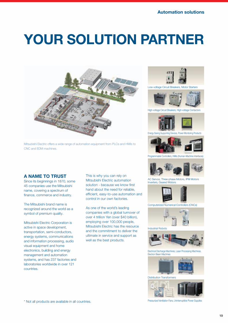
19
MEMO
Automation solutions
YOUR SOLUTION PARTNER
Mitsubishi Electric offers a wide range of automation equipment from PLCs and HMIs to
CNC and EDM machines.
* Not all products are available in all countries.
A NAME TO TRUSTSince its beginnings in 1870, some45 companies use the Mitsubishiname, covering a spectrum offinance, commerce and industry.
The Mitsubishi brand name isrecognized around the world as asymbol of premium quality.
Mitsubishi Electric Corporation isactive in space development,transportation, semi-conductors,energy systems, communicationsand information processing, audiovisual equipment and homeelectronics, building and energymanagement and automationsystems, and has 237 factories andlaboratories worldwide in over 121countries.
This is why you can rely onMitsubishi Electric automationsolution - because we know firsthand about the need for reliable,efficient, easy-to-use automation andcontrol in our own factories.
As one of the world’s leadingcompanies with a global turnover ofover 4 trillion Yen (over $40 billion),employing over 100,000 people,Mitsubishi Electric has the resourceand the commitment to deliver theultimate in service and support aswell as the best products.
High-voltage Circuit Breakers, High-voltage Contactors
Energy Saving Supporting Devices, Power Monitoring Products
Programmable Controllers, HMIs (Human-Machine Interfaces)
AC Servos, Three-phase Motors, IPM Motors Inverters, Geared Motors
Computerized Numerical Controllers (CNCs)
Industrial Robots
Electrical Discharge Machines, Laser Processing Machines, Electron Beam Machines
Distribution Transformers
Pressurized Ventilation Fans, Uninterruptible Power Supplies
Low-voltage Circuit Breakers, Motor Starters
•Trademarks
Ethernet is a registered trademark of Fuji Xerox Corporation in Japan.
Other company and product names herein are the trademarks and registered trademarks of their
respective owners. To ensure proper use of the products listed in this catalog, please be sure to read the instruction manual prior to use.
Safety Warning

Proposal for Upgrading/Introducing Inverters
HEAD OFFICE: TOKYO BLDG., 2-7-3, MARUNOUCHI, CHIYODA-KU, TOKYO 100-8310, JAPAN
Mitsubishi Electric Corporation Nagoya Works is a factory certified for ISO14001 (standards for environmental management systems) and ISO9001 (standards for quality assurance management systems).
L(NA)06096ENG-B(1610) MEE
FACTORY AUTOMATION