proposal template lp cerda2 sv5edited -...
TRANSCRIPT

1. Introduction This proposal concerns a combined experimental and theoretical study of highlynon-linear mechanical instabilities in thin films supported on compliant substrates. When sub-jected to compressive stress, such membranes respond by a variety of buckling instabilities.1–3
A.
B.
C.
I.
II.A.
B.
C.
III.A.
B.
C.
Figure 1: Wrinkle-to-fold instability I. on water in a 10µm polyesterfilm (wavelength l ⇠ O(cm), II. in a 100µm latex sheet bonded to asoft rubber (l ⇠ O(mm)), and III. in a 15nm gold nano-particle tri-layer at an air/water interface (l ⇠ O(µm). Where K is the effectivesubstrate stiffness and h is membrane thickness. These transitionsappear very similar despite the the wide variation in film thicknessand substrate stiffness
Of central interest to this proposal is thewrinkle-to-fold (W-t-F) transition when smallamplitude, uniformly distributed, wrinklestransform into large amplitude, highly local-ized folds.1–9 Two canonical cases, both in uni-axial compression, are illustrated in figure 1.Figure 1 I. shows an elastic membrane float-ing on a liquid surface.3, 4, 7, 8 Small uniformwrinkles develop at low levels of compres-sion. With increasing compression, most ofthe wrinkles relax whereas a single one growsinto a fold with high local curvature. The na-ture of this transition resembles a second ordertransition (the relevant order parameter, a ra-tio of amplitudes of the fold to the wrinkles,diverges continuously, see figure 5).3 Figure 1II. shows similar transition in a membrane at-tached to a soft elastic solid.3, 5, 6 Althoughboth phenomena are examples of strain focus-ing and appear visually similar, the underlyingphysics differs in crucial ways to be discussedlater. The W-t-F instability of liquid-supportedfilms is now well-understood, in particular,Diamant and Witten have provided an exactanalytical solution that describes the transi-tion in quantitative detail.6–8 In contrast, theW-t-F of membranes on soft solid substratesis still poorly-understood.3, 5, 6, 9 Some experi-ments have reported strain focusing occurs viaperiod-doubling transitions.5, 6, 9 Our own ex-periments (figure 1 II) do not show such reg-ularity. The effect of the ratio, Em/Es, of themodulus of the membrane, to the modulus of the substrate, or of the substrate thickness, or ofboundary conditions remains uncertain. We propose a theoretical, numerical, and experimentalstudy that aims to elucidate this situation.
In a broader sense, the interest in buckling behavior of thin membranes under compressionhas been driven by a wide range of natural systems: compression of lung surfactants,10–20 drying-induced buckling of pollen grains,21, 60 crumpling of paper,1, 22 wrinkles on skin,23, 24 and the inter-nal morphology of a host of biological tissues including arteries,26, 27 intestines,28, 29 and brain.30–32
In most of these cases, the membrane undergoing compression is attached to an elastic substrate.This project contributes to providing a unifying understanding in this regime. Over the last twodecades, crumpling,1, 22 wrinkling1, 2, 23, 24, 33–51/folding,3–9, 16–20 creasing, and other surface insta-bilities such as herringbone patterns in biaxially compressed supported membranes,24, 38, 45 edgeinstabilities,40, 43 capillary-tensile wrinkling,2, 36, 40–42 etc. have received immense attention in theliterature, often within the context of highly idealized models, unified under the umbrella of stress
1

focusing instabilities.1, 22, 52, 53 Within this umbrella, we aim for a unified description of the W-t-Facross a wide range of parameter space.
Intellectual Merit: The key hypothesis to be tested in this proposal is that the W-t-F transi-tion arises from a coupling between wrinkling and a different strain-focusing instability, viz.the creasing of the free surface of a compressed solid (see figures 2 and 8). Specifically, thepresence of wrinkles creates regions of the surface with local strain that is much higher thanthe nominal strain, and in these regions, the substrate is susceptible to creasing (see figure 8).
A. B.
C. D.
Figure 2: Creasing or cusping instability seen in A. a gel of styrene-isoprene-styrene (SIS) with no surface membrane. This same sub-strate is used for experiments with wrinkling/folding when a rub-ber membrane is attached to the surface, example data shown infigure 1 I. The creasing instability appears only at high compres-sive surface strains ecr ⇠ kH ⇠ 0.35, whereas folds are seen atmuch lower strains e f ⇠ 0.2 � 0.3. B. Finite element simulationof a linearly elastic gel showing creasing, nucleating at e ⇠ 0.4 C.and D. Show histology slides of human arterial cross-sections. C.shows nearly uniform folding of the internal boundary while D.shows collapse via a creasing instability.
By implication, the W-t-F must be sensitive toany defects that create strain inhomogeneities,and this will be tested as well. We note thatprevious analyses of the W-t-F have all focusedon the geometric nonlinearities arising fromdeformation of the membrane.3–8 Our hypoth-esis implicates geometric nonlinearities arisingfrom deformation of the substrate itself as thecrucial contributor to the W-t-F on soft solidsubstrates.
The essential underlying physics of ourmodel requires relaxing three key assumptionsfrom most previous analyses: (1) we will nolonger assume that the membrane modulus Emfar exceeds that of the substrate, Es, (2) we nolonger assume that geometric nonlinearity as-sociated with substrate rotation is negligible(large rotation of the film was already includedin previous analyses), and (3) in our proposedstudies of defects, we no longer assume geo-metric homogeneity, i.e. film thickness is al-lowed to vary (and therefore play the role ofdefects). Relaxation of these assumptions leadsto a rich new set of behaviors that will be vali-dated experimentally.Broader Impact: Beyond the immediate topicof fold formation, this research will provide
broader insight into complex buckling instabilities. Research results will be disseminated in peer-reviewed journals as well as conferences of the American Physical Society and the annual meet-ing of the American College of Surgeons. This project will support the training of one graduatestudent who will furthermore benefit from the international collaboration with Cerda. Pocivavsekhimself benefited from a similar experience as a graduate student. Undergraduates will be heavilyinvolved: specific tasks such as mechanical characterization of the materials, and implementationof the mechanical jig for applying strains, will be assigned as undergraduate research projects.The University of Pittsburgh encourages, and supports financially, recruitment of minority stu-dents into research activities, and has drawn undergraduate students from diverse backgroundsfrom all over the country. Velankar supports an active undergraduate research program, and hasmentored over 25 undergraduate students over the past several years, and published several ar-ticles with undergraduate coauthors.75, 77, 81–85 Pocivavsek has been involved in mentoring under-graduate students with multiple publications with undergraduate coauthors;3, 4, 16–18, 54 moreover,undergraduates and even a high school student were part of work published in Science3as well as
2

PRL.54
The proposed research is synergistic with all three participants’ research on buckling phenom-ena, and will benefit their other ongoing research. In particular, Pocivavsek and Velankar willbe able to apply the technique of particle-tracking-based strain mapping more broadly in theirresearch. This proposal will further advance the ongoing collaboration between three interdisci-plinary researchers with strongly complementary skills. Luka Pocivavsek⇤ is an M.D./Ph.D., atpresent a surgery resident, with a strong interest in mechanics. During his Ph.D. he focused on abroad class of membrane elastic instabilities in biological systems from folding in self-assembledmolecular films like lung surfactant3, 4, 16–18, 54 to hyperbolic-(excess)-cone instabilities in bowelanastomoses.55, 56 The past three years in Pittsburgh, Pocivavsek has continued his interests in ap-plying geometry and elasticity to medically relevant problems.56 His current interests in bucklingphenomena are related to the practice of surgery as described below. Enrique Cerda is a professorof Physics at University of Santiago in Chile, and has collaborated with Pocivavsek for severalyears. Pocivavsek spent significant time under Cerda’s mentorship during his Ph.D. Cerda’s in-terests are in theoretical problems coupling non-linear geometry and linear elasticity,2, 57–59 with aparticular focus on modeling soft matter and biologic systems (skin,23 lung surfactant,3, 4 pollengrains21, 60). Sachin Velankar is a faculty in Chemical Engineering with a background in poly-mer science, and strong interest in buckling phenomena. His recent research includes swelling-induced folding of films of cross-linked polymers, reversibly-buckling surfaces, and (in progress)buckling of membranes supported on viscous films.70–85 He is an active participant in Poci-vavsek’s ongoing research funded by a grant, from the American College of Surgeons, on usingsurface topography (wrinkling/folding) to control of biological adhesion. Most relevant to thisproposal is his experimental expertise and practical knowledge of polymer materials. This is crit-ical to design clean experiments that isolate the physical phenomena of interest.
Finally, we will undertake educational outreach to build connections with the surgery com-munity, which often deals with problems of a geometric and mechanical nature. Geometry andelasticity abound in surgical practice.61 Often in the operating room, surgeons discuss a particularoperation using terms like tension, pressure, collapse, and wrinkling. Likewise, materials used inmany surgical procedures involve thin membrane like structures as in hernia meshes and vascu-lar grafts.61, 62 These structures themselves are subject to complex loads and often respond withnon-linear instabilities such as buckling and wrinkling. The problem of hernia repair, a commonsurgery performed by Pocivavsek, is most closely related to this proposal. The basic problem ofa ventral hernia is to patch an abdominal wall defect (hole) with a piece of polymer membrane(mesh).61, 62 The problem has proven vexingly difficult with a reported surgical failure rate be-tween 10-30 % (the actual rates may be higher since patients often avoid returning to the originalsurgeon). The strategy of mesh placement and fixation is driven by empirical surgical knowledge.
⇤A significant portion of the intellectual background of the project comes from Luka Pocivavsek, and much of theoutreach to surgeons is his initiative as well. Nevertheless, he is not the PI on this proposal for the following rea-sons. Pocivavsek is a surgical resident at University of Pittsburgh Medical Center (UPMC). Having completed 3 of 5years of clinical training under an ACGME program, he is currently a research fellow in the Department of Surgeryat UPMC. For the next two years, he has few clinical responsibilities and has over 80% protected time for research.While UPMC and University of Pittsburgh share a name and geographic co-location, they are separate institutions.As such, Pocivavsek being part of UPMC does not have any official capacity or status with University of Pittsburgh.The authors of this proposal were faced with the decision of who to make PI given that they were all from differentinstitutions. Sachin Velankar being a member of a degree granting department with established laboratory space isthe obvious choice. While any student who will work on the proposed project will be co-mentored by Pocivavsek andVelankar, they will need to come from the University of Pittsburgh, since UPMC Department of Surgery does not havedegree granting graduate research programs. Moreover, the largest costs associated with the grant will be in the formof student support, again making Velankar the more obvious choice for PI.
3

To quote from standard practice guidelines published by the Surgical Clinics of North America(October 2013): ”The goal of mesh fixation in laparoscopic ventral hernia repair is to suspend themesh with equal overlap over all hernia defects and in a taut fashion, with no wrinkles or folds.This strategy aims to maximize mesh coverage of the defect and to obviate the chance of meshprotruding into the defect”.61 While a careful surgeon takes every precaution that the mesh isfree of wrinkles when initially implanted, the fundamental geometry of the laparoscopic ventralhernia repair is that a flat sheet is being used to patch a hole in a surface (the pressurized abdomi-nal wall) which has finite Gaussian curvature. Since hernia meshes are made from stiff polymerssuch as PTFE, polyester, or polypropylene, they are practically inextensible (and incompressible)membranes, thus wrinkles and folds cannot be avoided using currently available materials. Theboundary conditions are imposed by the surgeon when he/she transfixes the mesh perimeter withsuture and staples to the abdominal wall. Once the operation is complete and the abdomen de-flated, the boundaries move inward placing the mesh under a compressive load; furthermore, thegeometry of the abdominal wall returns to its more natural curved shape. The mesh adapts to itsnew confinement as expected by buckling (see figure 7). This is just one example; other surgerieswhich involve a coupling of mechanics and geometry includes suturing while avoiding scars23 (apast research topic for Cerda), and strictureplasty55, 56 (repairing scars on intestinal walls).
I. II.
T(ai) =
hernia meshmembranetopology
Figure 3: Ventral hernia repair and finite element analysis: I. intra-operative images (personal collection of Luka Pocivavsek) showinga polypropylene mesh fixed with suture and stapes around the perimeter under optimal laparoscopic intra-abdominal pressures;second image is taken as the pressure is reduced, the onset of wrinkling is clearly evident (especially along purple line which is usedfor orientation intra-operatively). Also shown is a close-up of the mesh and its inherent non-homogeneous geometry. II. Examples ofgeometric reconstructions of two hernia meshes derived from Computed Tomography (CT) scans, wrinkles and folds are observed inboth cases. These geometries are used for subsequent FEA under multiple clinically relevant loading conditions.
As part of the educational outreach of this grant, two two-hour courses will be developed forsurgical residence at University of Pittsburgh Medical Center. One of these will be coordinatedwith a planned visit from Cerda. The first course will focus on a brief and basic introduction todifferential geometry and membrane physics using a graphical approach and avoiding technicalequations. Topics of importance to ventral hernia repair will be discussed including: curvature,Gaussian curvature, Gausss Theorema Egregium, membrane elasticity and the preferred mode ofdeformation via bending modes, and boundary conditions. These will be further reinforced withhands on practical demonstrations, for example the coupling between curvature and elasticitywill be demonstrated by showing the ease of isometric transitions (bending a piece of paper into acylinder) but inherent difficulty of non-isometric ones (bending the cylinder into a torus). The goalof the lectures will be to provide surgical trainees with a basic set of tools in which to think aboutventral hernia repair from a more fundamental geometric vantage. Some of our research will beshared with the group during the first lesson. The residents will then be encouraged to think aboutpossible solutions to the mesh wrinkling problem in hernia repair. A second lesson will be heldat a later time point, at which resident derived solutions will be discussed and analyzed. Surgeryis a very intuitive and empirical field, many surgeons may have thought about solutions to the
4

mesh wrinkling problem however may have lacked the mathematical and physical language inwhich to communicate them. Our goal during the second lesson is also to provide hands onaccess to rubber sheet with which model solutions can be attempted; promising solutions willbe further analyzed by doing simulation based analysis with FEA. Our educational outreach willbe aided and supervised by the Associate Program Director for General Surgery at University ofPittsburgh Medical Center, Dr. Giselle Hamad. After deploying at the University of Pittsburgh intwo successive years, they will be made available to other teaching hospitals.
2. Background A variety of systems can be thought of as elastic membranes resting on softersubstrates. The inside wall of a muscular artery is covered by a thin elastic sheet, the internalelastic lamina, resting on a softer tunica media27 (see also figure 2). Our lungs are lined by a thinmembrane stabilized by lipids and proteins, which is often modeled as an elastic sheet on a fluidsubphase.3, 10, 11, 13–15, 19, 20 Many marine organisms like shellfish have organs covered with wrin-kles and have been extensively studied.16, 65, 66 Non-biological interfaces composed of semicon-ductors,50 gold nanoparticles,54, 63, 64 polymers,36, 51 and even sand33 have been treated similarly.
substrateH
A.
A0
A1B.
Figure 4: Geometry of wrinkling and folding: membrane is shownin blue, substrate occupies lower half-plane. Coordinate axis asdefined, H is substrate thickness, f is angle between membranetangent and horizontal plane, l is wrinkle wavelength. In B. wedefine the relevant amplitude parameters, where by convention welabel the fold amplitude as A0 and decaying wrinkling amplitudeas A1.
Understanding the mechanical stability ofsuch elastic interfaces has great technologi-cal and biomedical potential.10–12, 24, 35, 45, 55, 56
Over several decades, theoretical approacheshave been developed to treat particular casesof either wrinkling1, 2, 25, 37–44, 47–49 or fold-ing3–9, 19, 20 for specific systems. Figure 4A il-lustrates the geometry of the specific problemconsidered here, rectilinear compression of amembrane supported on a compliant substrate(liquid or soft solid) of thickness H. An end-displacement d is applied to impose a nominalstrain e = d/L, where L is membrane length.For this situation, Pocivavsek and Cerda were the first to integrate wrinkling and folding as partof a more general surface instability: the wrinkle-to-fold model (W-t-F), unifying diverse systemsbased purely on geometry and linear elasticity.3, 4 This was done by considering the floating mem-brane as an inextensible thin sheet (i.e. contour length remains L) and considering only its bendingenergy (Ub) while defining a general potential for the substrate (Us):
Ub + Us =B2
Z
Lf2ds +
K2
Z
Lus ds (1)
where B is membrane stiffness, K describes an effective substrate stiffness, us is the substratedisplacement field, and all derivatives are taken with respect to membrane arc length s. Theinitial work of Cerda and Pocivavsek3 uses the inextensibility of the top membrane to define theLagrangian with a global constraint
L ⇠ Bf2 + Kus � P(1 � cos f � ed) (2)
where the Lagrange multiplier P is related to the load necessary to constrain the membrane. Forliquid substrates, the above formalism predicted that uniform wrinkles of wavelength appearedat small strain. At larger displacements, a localized fold appeared. The model correctly capturedthe entire wrinkle to fold instability (using us = y2 and K = rg), i.e. the entire sequence ofinitial growth of A1, and subsequent growth of the order parameter A0/A1. Its numerical solution
5

correctly predicted the amplitude scaling in both regimes (see figure 5 Liquid Substrate, soliddark lines are numerical solutions plotted with experimental data). Importantly, it identified thewrinkle wavelength l as the key length scale for the W-t-F: specifically, amplitude data from awide range of experiments superposed when plotted as a function of d = e ⇥ L/l. Furthermore,subsequent theoretical work by Witten and Diamant elegantly showed that the Euler-Lagrangeequation derived from L was a higher order member of the stationary-sine-Gordon-modified-Korteweg-de Vries hierarchy (sG-mKdV).6–8 This is why the Introduction above stated that ”W-t-Finstability of liquid-supported films is now well-understood, at least for rectilinear compression”.
0.05 0.1 0.15 0.2 0.25 0.3 0.35 0.40
5
10
15
20
25
30
0 1 2 3 4 5 6 7 8 90
5
10
15
20
25
30
LIQUID SUBSTRATE
ELASTIC SUBSTRATE
! = 5 - 25 mm
"
L"/! = d
0.0 0.2 0.4 0.6 0.8 1.00
2
4
6
8
10
12
14
0.0 0.2 0.4 0.6 0.8 1.00.0
0.1
0.2
0.3
0.4
0.50.0 0.2 0.4 0.6 0.8 1.00.0 0.2 0.4 0.6 0.8 1.0
A0/A
1A
0/A
1
A0/A
1
! = 14 - 40 mm
A0 ~ "
A0/1
~ (")0.5
A1
d
d
"c=0.05
wrinkle
fold
"c ~ !/L
Em/Es = 50 - 250
H = ! (0.5 - 3)
!c ~ g(", H, Em/Es, !
s) ?
"c=0.2 0.3
Figure 5: Liquid substrate data taken from Pocivavsek and Cerda’s work onwrinkling and folding on water, Science 320, 912 (2008). On liquids the crossover regime from wrinkling to folding is easily tracked by a divergence of am-plitude ratios A0/A1. The only parameters necessary to normalize the data arewrinkle wavelength and system size, as such plotting the order parameter ver-sus d = e ⇥ L/l collapses data for all wavelengths. On the right, we show un-published data for elastic substrates (SIS substrates with rubber membranes). Arange of wavelength, substrate thickness, and moduli mismatch parameters wastested. The order parameter scaling shows much more diverse behavior oncefolding begins. Most importantly, d = e ⇥ L/l no longer normalizes the data asevidenced in the lower plot where A0/A1 is plotted against d. Furthermore, foldnucleation and growth appears to occur over a range of values unlike the singlevalue seen on liquid substrates.
We now turn from liquid sub-strates to soft solid substrates. Whilethe qualitative similarity between theW-t-F instability on liquid and elas-tic substrates is clear, the details arefar more complex. Wrinkling onsoft elastic substrates can be stud-ied in the limit of small deformationsand linear elasticity, indeed wrin-kling is the first order linear solutionto the above problem (linearalizingL provides the exact wrinkling so-lution). Cerda and Mahadevan2 us-ing dimensional analysis predicted avery general scaling law for wrin-kling more than ten years ago: l ⇠(B/K)1/4, using the definition K =Es f (l/lp) /lp, where lp is a charac-teristic substrate penetration length.Their scaling arguments allowed forany substrate that could be charac-terized by K; indeed, the exact prob-lem their work studied had no phys-ical substrate whatsoever, i.e. ten-sional wrinkling. Concerning wrin-kling on liquids, this scaling easilygave l ⇠ (B/rg)1/4, which was inagreement with the above exact so-lutions.3, 5, 7, 8, 46 On elastic substrates,
they predicted two limits dependent on substrate thickness H: deep limit l ⇠ t(Em/Es)1/3 andshallow limit l ⇠ (tH)1/2(Em/Es)1/6 (both have been validated subsequently with exact calcu-lations and experiments5, 47, 48). Overall, the wrinkle instability on fluids and elastic substrates iscaptured extremely well by only three parameters: Em/Es, t, and H. As expected for leading orderlinear solutions, wrinkling (l) is rather insensitive to many details in the problem.
Folding, however, is highly non-linear as the extensive work on liquid substrates has shown.Moreover, current experimental data (unpublished) shows that there is substantial difference be-tween folds on different substrates (see Figures 1 and 5). One signature of the W-t-F instability ona liquid substrate is the switch from a square root relation between amplitude and external strain,A1 ⇠
pe, to a linear relation, A0 ⇠ e.3, 4, 7, 8 One consequence of this is that the transition order
parameter (A0/A1) is dependent only on l and L. In contrast, Figure 5 highlights that on elastic
6

substrates A0/A1 shows important differences: 1. onset of the folding instability is at much higherstrains closer to 0.2 compared to 0.05 on liquids, 2. folds appear to nucleate throughout a rangeof critical strains and their rate of growth shows a spectrum of values, 3. the parameter d whichnormalized all the data for the liquid substrates clearly does not normalize the data for soft solidsand neither does any simple combination of parameters l, Em/Es, or H.
Theoretical approaches to folding on elastic substrates have proved challenging.5, 6, 9 Impor-tant work by Brau et al.5 used the above formulated L and studied it with an elastic descrip-tion of the solid substrate, while ignoring finite rotations and substrate nominal strain. Ap-plying perturbation theory, they looked for solutions of the following form: uy(x, y = 0) ⇠C1 cos(qx) + C2 cos(2qx), where C1 =
pe and C2 = e (a strong approximation about ampli-
tude scaling based on liquid substrates). As is appreciated in the construction of the above func-tion, their weakly non-linear solution to the W-t-F problem on elastic substrates leads to period-doubling. Brau et al. showed the challenge of integrating elasticity for the substrate into theproblem, and their work is a formidable first step. However, their solution fails to capture someof the important differences mentioned above: broad range of critical strain for fold nucleation,differential growth rate, and geometric asymmetry. The last point we have yet to mention; how-ever, it is one of the most qualitatively apparent differences among elastic and liquid systems. Onliquids, one fold appears and grows, absorbing any further compressive strain, i.e. once strainfocusing occurs at one location, it can relax strain in the entire system.3, 7, 8 On elastic solids, mul-tiple folds, at some characteristic spacing l0, appear, because a fold can only relax strain withina certain distance. However, our preliminary experiments show that fold distribution is oftenasymmetric (figure 1 I.). This asymmetry is also captured by our simulations (see figure 11) and isseen in biological systems (see figure 2), where l0 does not follow any simple integer scaling withl. The period-doubling solution naturally presumes such symmetry must exist. Thus at the heartof folding on elastic substrates must be a symmetry breaking instability: l0 6= n · l.
One of the key assumptions in the previous works already cited is the large mismatch in stiff-ness. But the whole richness of the system is not captured in this limit. A different surface insta-bility, first studied by M. Biot in his book “Mechanics of Incremental Deformations”67 and named“creasing” or “Biot instability”, happens when the membrane and substrate have the same stiff-ness, i.e. equivalent to the surface of a homogeneous solid (see figure 2). The limit is singular sincethe only length scale of the problem, membrane thickness, is meaningless. A breakthrough for thisproblem was given by Holfeld and Mahadevan68 where they carefully studied numerically the in-stability in the limit of vanishing bending stiffness of the upper membrane. Their analysis showedthat the instability is extremely sensitive to imperfections at the free surface and one example isthe presence of a “skin” or membrane on top. Thus, it remains an open problem to understandhow this instability works in the presence of a membrane. In fact, the same work showed that theproblem is singular but regularized because of the presence of a membrane. However, the highlynonlinear nature of the instability makes its study harder. The work of Holfeld and Mahadevanand others69 show that material and geometric nonlinearities seem important. They use a neo-hookean or hyperelastic material model and assume incompressibility. Hence, the numerical andtheoretical analyses have elements related to these specific assumptions.
3. Planned Research Relaxing the three key assumptions outlined in the Intellectual Merit sec-tion form the guiding themes. The overall goal is to bring clarity and unity to the folding insta-bility on solid substrates and in non-homogenous membranes. The rich work on liquid substratesshows that a beautiful universality is at work in these instabilities captured fully by an equationthat previously had no associated physics. The qualitative similarity between liquid and elasticsubstrates, as well as the immense ubiquitousness of such surface instabilities in natural systems,strongly suggests a fundamental universality exists in the elastic case as well. The goal of our
7

work is to experimentally and numerically study a wide parameter space upon which a theoreticalmodel can be refined and developed. Our general approach will be three pronged: experiments,simulations, and analytical theory. The simulations and experiments are used simultaneously toguide selection of parameters and for cross-validation. The theoretical work is built upon theexperiments and simulations. Our preliminary data described below shows the fruitfulness andsynergy of this approach. In particular, the connection between substrate elastic instabilities likecreasing and membrane folding.
Experiments: Past experimental data explore a very limited part of parameter space l = 0.1� 3mm, Em/Es ⇠ 100, while substrate thickness (H) has never been explicitly studied in the foldingregime. Figure 5 shows our preliminary data on styrene-isoprene-styrene (SIS) substrates withrubber membranes, where the parameter space studied was narrow. The experiments proposedin this grant will expand this parameter space even further. Relevant measurements will includesurface profile (l and amplitudes Ai), nominal strain (e), and local strain fields in the membraneand substrate (elocal).
Material Preparation: To expand the parameter space, most experiments will be conductedusing two types of materials: either polydimethylsiloxane silicone elastomer (e.g. Sylgard) orstyrene-isoprene-styrene (SIS) triblock copolymers (e.g. Kraton). The silicones are two-part for-mulations in which two viscous liquids, the base resin and the crosslinker, are mixed together, andthen allowed to cure into an elastomer. The great advantage of silicones is that large variation inmodulus can be realized, for instance, Palchesko et al 2014 realized moduli ranging from 0.005MPa to 1.7 MPa by simply mixing two commercial grades (Sylgard 184 and Sylgard 527) in vari-ous proportions. Other ways of tuning the modulus (e.g. reducing the crosslinker concentrationor adding linear PDMS) can also be employed. Thus the stiff films and the soft substrate are chem-ically identical and covalently bonded to each other (see below), and hence delamination can beavoided altogether even with severe compression.
The SIS materials are commercial thermoplastic elastomers, and grades ranging from 13%styrene to 70% styrene which changes the modulus over 50-fold are available commercially.The modulus can be tuned by adding linear polyisoprene or linear polystyrene to reduce or in-crease the modulus respectively, and once again excellent compatibility between the film and thesubstrate guarantees excellent adhesion.
These materials offer two key advantages: first, both can be deformed to relatively high strains(up to 40% in tension) without significant deviation from linear elastic behavior. Second, both aretransparent. A key hypothesis of this proposal is that the W-t-F transition arises because strainlocalization in the substrate induced by wrinkles makes the system susceptible to the creasinginstability, even when the nominal strain is low (see figure 8). Testing this requires measuring thestrain in the substrate near the film, and transparency is a key requirement. If very high modulusratios (exceeding 104 are needed) evaporated gold films deposited on silicone (with a titaniumadhesion layer) will be used; these are however opaque and will not permit strain visualization
Mechanical properties of the films and the substrate materials will be measured in uniaxialtension (using an Instron machine) and in shear (using a parallel plate rheometer). Bilayers willbe prepared as follows. For silicone systems, the membrane silicone will be cast onto an acrylicsurface. A small quantity of volatile solvent may be added to aid spreading. Upon partial curing,the substrate silicone will be poured and the bilayer system allowed to cure fully. Due to the pres-ence of unreacted bonds in the partially-cured sample, covalent cross-linking across the interfaceis expected. In case of SIS, the film will be compression-molded under molten conditions againsta steel plate in a platen press using spacers to control film thickness. The softer SIS substrate ma-terial will then be molded against this film at a lower temperature. The samples of figure 5 abovewere made by this procedure. If thickness variations are desired, a patterned surface (acrylic or
8

steel) will be used when preparing the film. Strain will be imposed in three different ways. For
micrometer screw drive
oil immersion
objective
c
rubber
substrate
film
A. B. C.
rubber base
pre-stretched rubber base
relaxed rubber base
!
substratefilm
oil
immersionmicrometer
screwdrive
Figure 6: The bilayer sandwich is attached to a thick rubber substrate (green) and bent to induce buckles. b. The bilayer sandwich isattached to a pre-stretched rubber substrate (green), and then the pre-stretch is relaxed to induce buckles. c. For visualization experi-ments, a thick sample will be squeezed in a vise. The base of the sample will be lubricated to ensure full-slip boundary conditions. Alayer of oil (not shown) will be placed above the sample to eliminate any lensing effects from the buckled surface.
experiments requiring only modest strain, the bilayer will be bonded to a thick sheet of stiff rub-ber which will then be bent to the desired curvature (see figure 6a). This is the same procedure asused in our preliminary data with SIS/rubber system (see figure 1 II. and figure 5) and in the liter-ature. It is difficult to realize a large and homogeneous strain in large samples using this method.In those cases, the bilayer will be attached to a pre-stretched sheet of rubber (once again, siliconerubber sheets and silicone adhesive will be used to ensure good bonding). The pre-stretching willthen be relaxed to induce homogeneous compression throughout the length of the sample evenwhile the sample remains flat (see figure 6b). This idea of using a stiff, pre-stretched rubber sheetas a “handle” to apply a large strain homogeneously was also used in our previous research (seefigure 7). In that case, a film floating on a highly viscous liquid was compressed to induce buckles.The chief differences as compared to our previous research are that in the proposed experiments(a) the compression will be quasi-static (i.e. the compression rate will be low), (b) in figure 7, anelastomeric tray was necessary since the substrate was a liquid, whereas in the proposed experi-ment, the underside of the substrate can be bonded to the rubber sheet directly.
strain
rate
c
d
e
f
b a compression
starts
Figure 7: a. Schematic of buckling of elastic films on viscous substrates. An rectangular film (orange) floats on a liquid layer (blue)contained in an elastomeric tray (white). The tray is itself bonded to a stiff rubber sheet (green) pre-stretched as indicated by thearrows. Relaxation of the pre-stretch induces buckling of the sheet. b. The compressive strain measured from the digital imagecorrelation (DIC) analysis of markers on the elastomeric tray. The slope is the compression rate. c-f. Images of the buckling film atvarious times during the buckling process indicated by the red marker points.
Numerical Simulations: Experiments will be supplemented with numerical data using finite ele-ment analysis. The commercial package ABAQUS will be used (current license belonging to LukaPocivavsek and used primarily for work related to an ACS grant on topography induced de-adhesion). Preliminary simulations presented throughout this grant show the capability of FEAto accurately capture W-t-F instabilities at the correct strains under multiple boundary conditions.Given rather simple and well defined geometries of the initial state, robust structured meshes are
9

used throughout with linear hexahedron reduced integration elements (C3D8R).E
m/E
s =
100
!=0.4
Em
/Es =
1
kct = "/2#•t = 0.33
!=0.41
!=0.20
!=0.26
!=0.33
!=0.40
!local=0.4-0.6
!local > 0.6
!=0.41
Figure 8: Finite element simulations of an elastic substrate/membrane systemwith Em/Es = 1 and Em/Es = 100, both materials are treated as linearly elas-tic solids. The systems are uniformly compressed in the horizontal direction,boundary conditions being applied to the end planes and moreover the bottomplane being constrained to simple horizontal motion. The deformation geom-etry is shown with the strain field imposed in color; only compressive (nega-tive in this notation) strains are colorized, any tensile strains are uniformly gray.The membrane has been removed to allow visualization of developed surfacestrains at the substrate/membrane interface. In the no-modulus-mismatch case,the block undergoes uniform compression as expected up to e = 0.4, at this pointmultiple creasing instabilities develop along the unconstrained surface (ecr). Theinstability shows strong signs of criticality as the instabilities appear randomlyand grow uncontrollably. In the higher mismatch system, wrinkling appearsuniformly. The wavenumber of the wrinkling instability is matched by existingscaling laws, validating the simulation to this point. The near-surface strain fieldin the substrate (elocal) is not uniform showing an alternating pattern of compres-sion and tension following the wrinkle imposed local displacements. At certainpoints elocal approaches ecr , interestingly it is along these points that folds nucle-ate and grow.
Given the highly non-linear buck-ling and post-buckling structures ofinterest and complex contact condi-tions at the interface, the dynamic-explicit solver will be used primar-ily. In particular, the simulationswill provide a method to define re-gions of parameter space where de-sired instabilities are observed, al-lowing experiments to be more ef-ficiently tailored. We also havethe capability to directly import ex-perimentally derived membrane ge-ometries (profiles) or substrate strainfields into the FEA solver (exampleof this shown with hernia work infigure 3). These can be used to cre-ate predefined strain fields as initialconditions for the numerical analy-sis, and serve as further validationof the numerical procedures. Alsoimportantly, as mentioned in the ex-perimental materials section, manyof the desired instabilities occur athigh strains, 0.2 and greater. Whilewe have chosen materials that re-main linearly elastic over a broadrange, eventually non-linear stress-strain effects will become impor-tant. FEA simulations easily allowfor a variety of constitutive modelsincluding ones where experimentaldata from material characterization(as is described above) are directlyused in the analysis. By doing sim-ulations with both idealized linearlyelastic and real material propertiesallows us to gauge the effect of mate-rial non-linearity on the instabilities.Moreover, since theoretical work will be focused on geometric non-linearities within the confinesof linear elasticity, these simulations will provide an important bridge and validation betweentheory and experiment. Figures 2, 3, 8 , 10, and 11, contain examples of preliminary simulationsand highlight our ability to carry out the research plan.
3.1 Wrinkle-crease coupling: To be conducted in years 1 and 2: A key hypothesis of this pro-posal is that elastic instabilities in the substrate are coupled to membrane folding which becomes
10

increasingly important as the stiffness mismatch between the two materials decreases. Most ofthe previous theoretical work studying wrinkling or folding is implicitly done in the limit of largemismatch. The reason is that one uses plate theory or the Euler Elastica to describe the defor-mation of the membrane. This approach is only valid in the large mismatch limit. Plate theoryassumes that compressive stresses are larger than shear stresses because free boundaries at bothsides of the membrane enforce almost zero shear stresses. In fact the typical shear stresses sxycompared to compressive stresses sxx scale as sxy/sxx ⇠ t/L where L is the size system. When amembrane is attached to an elastic substrate, we can imagine that this is still true if the substratestiffness is small (Es ! 0 makes the upper membrane to behave as free). However, for low modu-lus mismatch the situation is different, shear and compressive stresses are comparable so that platetheory is no longer valid. We know that current experimental data for folding on elastic substratesis largely confined to a modulus mismatch regime of 50-250, where plate theory approximationssuch as those by Brau et al.5 fail to predict the broad range of critical strains for fold nucleation,different fold amplitude growth rates, and asymmetry in fold spatial distribution (l0 6= n · l).
Folding requires a “skin” or a membrane that is stiffer than the substrate, however creasinghappens in an elastic material free of a skin (see figure 8). This last instability was first reportedby Maurice Biot in the context of finite elasticity, as discussed in section 2. The exact cross-overdomains for larger versus low modulus mismatch are poorly understood. We do know that in thelimit of Em/Es ! • occurring for liquid substrates, plate theory perfectly captures the physics.Furthermore, in the limit Em/Es ! 1 Biot creasing appears as nominal strains approach 0.4. Bothinstabilities are inherently non-linear geometrically and importantly show stress focusing. Wehypothesize that by connecting these two different localizations mechanisms, the more randomnature of folding on elastic substrates can be answered, in particular we seek to understand dis-tributions in fold spacing, evolution of A0 with strain, and fold nucleation strains.
Simulations and Experiments: Figure 8 shows FEA simulations where surface instabilities (creas-ing) are captured within the limit of zero modulus mismatch and linear elasticity. Importantlythese instabilities begin to occur as critical strain approaches 0.4, as is captured by preliminarycalculations plotted in figure 9 and discussed below. It is noteworthy that in this simulation nocharacteristic length scale appears, the crease is infinitely sharp, and the spacing between creasesis random. In contrast, in the lower half of figure 8, where a bilayer system is modeled, at smallstrain, a characteristic wrinkle wavelength appears which agrees with previous linear stabilityanalysis (see section 2). Upon further compression, the surface relaxes into folds in a general pat-tern strongly resembling experiments (see figure 1 II.). These preliminary simulations give furtherinsight into local strain fields, not captured in previous experiments. Specifically, critical creasingstrains are locally approached in the substrate within a near surface layer even when nominalsubstrate strains are much lower. Those regions of higher substrate strain, to first approximation,have access to the creasing instability; moreover, the simulations show that this is where mem-brane folds nucleate. This strongly points to the hypothesis of a wrinkle-crease coupling. The goalof our simulations will be to study the role of modulus mismatch (ratio 1-1000), with particularattention paid to the evolution of near surface strains and their deviation from nominal strain inthe system.
Experimentally it is desirable to measure the strain in the film and/or substrate. Here, a smallamount of fluorescent particles (to be purchased) will be added to the film and to the substratewith fluorescence at different wavelengths in each layer. Samples will be held in a rectilinear com-pression jig (see figure 6c) (to be built in house) with a manual screw-driven clamp. This methodcannot realize homogeneous strains over very large samples, and furthermore only thick sampleswill be used to ensure that the entire sample does not buckle out of plane. Thus although easyto implement and well-suited for microscopy, it cannot replace figure 6b for all the experiments.
11

0 2 4 6 8 10 12 140.0
0.1
0.2
0.3
0.4
0.5
Figure 9: Marginal stability curve e = e(kn) for H/t ! • and twovalues of mismatch (Y = Em/Es). The minimum value defines thecritical strain ec. Strains lower than ec are stables. On the contrary, ife > ec the system is unstable with a most unstable mode kc.
An oil immersion objective will be used toeliminate any lensing from the buckled sur-face. The displacement of the particles willbe tracked using digital correlation methods.We note that typical wavelengths in the 100µm range are expected and hence displace-ments will be large, and can be tracked eas-ily. Prof. Lance Davidson from the Bioengi-neering Department routinely uses fluores-cent tracking to calculate strains developedduring embryo development and has agreedto assist with the data analysis of these ex-periments.Theory: We believe that studying the problemin the linear elasticity framework and ap-proaching the Biot instability from the limitEm/Es ! 1 not only regularizes the problem,but also helps to understand the creasing instability without using material nonlinearities. Weplan to do a global analysis of the buckling instability without assuming plate theory to describethe membrane. In particular, this involves including the role of finite rotations both in the mem-brane and substrate. Such rotational effects are routinely taken into account for the membrane,and indeed this is the hallmark of plate theory. However, given the preliminary simulations, itis apparent that substrate near-surface shear stress becomes comparable to nominal compressivestress (sxy ⇠ sxx), therefore finite rotations in the substrate should not be ignored. To avoid unnec-essary complexity, we will first restrain the analysis for zero Poisson ratio materials that avoidscoupling in the z direction. This assumption also cancels out anticlastic curvatures and simpli-fies greatly the analysis. We expect that most of the linear and nonlinear behavior can be captureby this assumption. Specifically, we will obtain the instability for low mismatch and include thethickness of the layer H. The few examples in the literature for finite elasticity where the generalproblem of buckling is studied in this sense68, 69 mix the effect of rotation (or geometrical non-linearities) with the nonlinear response of the material (or material nonlinearities). Buckling is alinear problem that couples compressive stresses to the transversal direction through a Laplacetype of effect so that material nonlinearities are not necessary for the analysis. Hence, we expectthat a linear analysis of the full elastic equations will capture the instability for low mismatch. Wehave done preliminary calculations showing that this analysis works and can give the marginalstability curve e = e(k) for a given value of membrane thickness and modulus mismatch (seefigure 9).
An important insight in this direction is that the linear analysis of the equations for zero pois-son ratio gives a similar marginal stability curve to the one obtained by M. Biot in the limit ofEm/Es ! 1. Thus incompressibility and material non-linearity are not key factors, and the systemcan have a creasing instability even when it is constrained to deform in the plane x � y. This pre-liminary work coupled with the simulations, also done using linear elasticity, shows the creasinginstability has more a geometrical origin than anything related to material properties.
Our linearly elastic equations taking into account finite rotations in membrane and substrateeasily capture the dominant and well defined length scale (wrinkle wavelength l) for high sub-strate mismatch (see figure 9 Em/Es = 100 where the kct corresponding to the strain minimumis matched by the wavenumber appearing in the simulations for a similar Em/Es in figure 8). To
12
capture the coupling between creasing and folding as seen in the simulations, we plan to studysystems with low modulus mismatch. It means the membrane is slightly stiffer than the substrateand approach the limit Em/Es ! 1. This must be a singular limit since the interface disappearsand then the thickness of the membrane.
!’
T(bi)
early folds at defects
!1 !2
late folds independent of defects
!1’’ !2’’
t1/t2=2
t1 t2 t1 t1t2
"=0.05
"=0.1
"=0.15
"=0.35
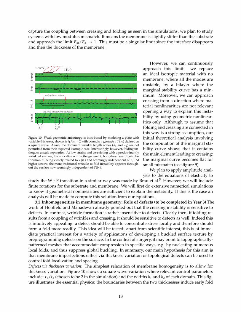
Figure 10: Weak geometric anisotropy is introduced by modeling a plate withvariable thickness, shown is t1/t2 = 2 with boundary geometry T(bi) defined asa square wave. Again, the dominant wrinkle length scales (l1 and l2) are notperturbed from their expected isotropic case. Interestingly, however, folding un-dergoes a scale separation. At low strains and co-existing with a predominantlywrinkled surface, folds localize within the geometric boundary layer; their dis-tribution l0 being closely related to T(bi) and seemingly independent of li . Athigher strains, the more traditional wrinkle-to-fold instability appears through-out the surface now seemingly independent of T(bi).
However, we can continuouslyapproach this limit: we replacean ideal isotropic material with nomembrane, where all the modes areunstable, by a bilayer where themarginal stability curve has a min-imum. Moreover, we can approachcreasing from a direction where ma-terial nonlinearities are not relevantopening a way to explain this insta-bility by using geometric nonlinear-ities only. Although to assume thatfolding and creasing are connected inthis way is a strong assumption, ourinitial theoretical analysis involvingthe computation of the marginal sta-bility curve shows that it containsthe main element leading to creasing:the marginal curve becomes flat forsmall mismatch (see figure 9).
We plan to apply amplitude anal-ysis to the equations of elasticity to
study the W-t-F transition in a similar way was made by Brau et al.5 However, we will includefinite rotations for the substrate and membrane. We will first do extensive numerical simulationsto know if geometrical nonlinearities are sufficient to explain the instability. If this is the case ananalysis will be made to compute this solution from our equations.
3.2 Inhomogeneities in membrane geometry: Role of defects (to be completed in Year 3) Thework of Hohlfeld and Mahadevan already pointed out that the creasing instability is sensitive todefects. In contrast, wrinkle formation is rather insensitive to defects. Clearly then, if folding re-sults from a coupling of wrinkles and creasing, it should be sensitive to defects as well. Indeed thisis intuitively appealing: a defect should be able to concentrate stress locally and therefore shouldform a fold more readily. This idea will be tested: apart from scientific interest, this is of imme-diate practical interest for a variety of applications of developing a buckled surface texture bypreprogramming defects on the surface. In the context of surgery, it may point to topographically-patterned meshes that accommodate compression in specific ways, e.g. by nucleating numerouslocal folds, and thus suppress global buckling. In summary, our main hypothesis for this aim isthat membrane imperfections either via thickness variation or topological defects can be used tocontrol fold localization and spacing.Defects via thickness variation: The simplest relaxation of membrane homogeneity is to allow forthickness variation. Figure 10 shows a square wave variation where relevant control parametersinclude: t1/t2 (chosen to be 2 in the simulation) and the widths b1 and b2 of each domain. This fig-ure illustrates the essential physics: the boundaries between the two thicknesses induce early fold
13

localization. Far from the folds, wrinkles appear e.g. figure 10 , e = 0.15). At higher strains, newfolds appear even far from the defects. We recognize that the early folds may not necessarily ap-pear at the boundary between thicknesses: depending on thickness variation, width of the thickand thin regions, and abruptness of the thickness change (square wave vs. gradual variation),early folds may appear at different locations of the thickness profile.
The chief hypothesis of this section is that that if the defect spacing is made comparable tothe wrinkle wavelength, then wrinkling will be suppressed altogether: only the thin regions willfold, whereas the thicker regions will remain unbuckled. Moreover, since a single fold can relaxcompression over a longer distance when substrate thickness is large, this idea of using defects tonucleate folds will become less effective as H reduces.
isotropic membrane topologic defects
Em
/Es
= 1
00
!=
0.1
!=
0.2
Em/Ed=" Em/Ed=0.01
#
#’
T(ai)
Em/Ed=1
folds along defects folds away from defects
Figure 11: Finite element simulations using a linearly elastic membraneand substrate show the effect of topology on fold localization. Fold dis-tribution in isotropic membranes is often random where l0 6= n · l (seealso figure 1 II.C.). Topological defects introduce a new length scalefunction (T(ai)), where ai characterize defect geometry and distribution,and a new dimensionless modulus ratio (Em/Ed), where Em, Es, and Edare membrane, substrate, and defect moduli, respectively. Simple ex-amples of cylindrical defects show that while the wrinkling instability isweakly perturbed, Em/Ed can be used to control l0. Our aim is to definethe functional relation between fold distribution and defect parameters:g(l0) µ h(T(ai), Em/Ed).
These hypotheses will be tested, first bysimulations, and then experimentally. Ini-tial simulations will be conducted with afixed t1/t2 ratio and varying the b1 and b2.Later simulations will consider the limit-ing case of t1/t2 ! •, i.e. the thin re-gions being able to wrinkle and fold veryreadily. Experiments will be conducted tovalidate the simulations.Topological defects: Finally, we will con-sider defects that take on the form ofholes in the membrane. This is specificallydriven by the desire to design patternedsurgical meshes that respond to compres-sion in a specific fashion: from a man-ufacturing viewpoint, through-thicknessholes are easier to implement than thick-ness variations. Moreover, this can relievebiaxial compression, and indeed one mayconceive of specific 2D patterns that showunusual mechanical behavior. Figure 11illustrates preliminary simulations of uni-directional compression of a supported membrane with holes. In this case, the hole spacing ischosen to be comparable to the wavelength. As expected, the holes act as fold nucleation sites andwrinkling of the reminder of the membrane is suppressed. In contrast, if the “holes” had a highermodulus, then folds avoid these defects. Once again, initial simulations will test round holes witha variety of spacings (as normalized by wrinkle wavelength of the corresponding homogeneousmembrane.) In this case, two limiting cases - when the area fraction of the holes approaches zeroor 1 - will be examined. As above, experiments will be conducted in specific cases of interest tovalidate simulations.Theory: Functionally, the above membranes can be characterized by how the gradient of thickness(or modulus) changes from one domain to the next (for a square wave the derivative in thick-ness is discontinuous, but in other profiles it can be made smooth). We have already developed atheoretical framework to study the linear stability of a layered system without using any specialassumption (see above) about the thickness of the film or the mismatch of stiffness in the system.Therefore, our analysis can be used to study the stability of films with varying periodicity in thick-ness or stiffness. The matching of the different linear solutions along the horizontal direction can
14

be obtained by using the continuity of displacements and stresses. One of the questions we wouldlike to answer analytically and numerically: is there a resonant condition when the geometric pe-riodicity of the films coincides with the natural wavelength of the wrinkles in the system.4. Prior NSF support: Results of prior NSF support: ENG-CBET-0932901, Sept 2009-July 2013(with no-cost extension), $290,087, ”Particles at polymer/ polymer interfaces: Interfacial phenom-ena and morphology control in immiscible polymer blends. Neither Velankar nor Pocivavsekhave received prior NSF support for research on buckling phenomena. Instead we will summa-rize results of one NSF project on interfacial phenomena in polymer blends. In Pickering emul-sions, particles that are partially wetted by oil and water adsorb at the interface between oil andwater and stabilize emulsions. This grant transplanted some of that research to polymeric sys-tems, specifically to use interfacially active particles to control the structure of two-phase polymerblends. We developed a model system composed of polyethylene oxide (PEO) as the drop phase,polyisobutylene (PIB) as the matrix polymer, and silica particles.70, 71 With silane modification ofparticles, we realized two different wettabilities (Fig. a,c). Addition of these particles to PEO/PIBblends with a droplet/matrix morphology induced remarkable structural changes. The chief re-sults were: (1) low levels (⇠ 0.1 vol%) of particles caused massive increases in the PEO dropsize, regardless of particle type. This was surprising: particles that are preferentially-wetted bythe continuous phase were believed to prevent coalescence.72 (2) At higher loadings (⇠ 1 vol%),particles that sat symmetrically at the interface could jam the interface and make the drop phasehighly non-spherical (Fig. b). (3) particles that were preferentially-wetted by the continuous phasecould bridge across two drops, and thus glue the drops into large clusters (Fig. d). (4) Particle-induced clustering caused large changes in rheology: e.g. the blends developed a yield stress.
Figure 12: All images refer to the PEO dis-persed phase after washing away the continu-ous phase PIB. OTS=octadecyltrichloromethylsilane;DCDMS=dimethyldichlorosilane. OTS-modified par-ticles (a) are preferentially-wetted by PIB, whereasDCDMS-modified particles (c) sit symmetrically onthe interface. Blend with addition of ⇠0.8 vol%DCDMS-modified particles shows highly elongateddispersed phase (b), and magnified image shows aparticle-jammed interface. OTS-modified particles atlow loading showing bridged structure (d).
Intellectual merit: This research illustrates how lit-tle the multiphase flow community knows about three-component fluid/fluid/particle systems. For instance,the changes in viscosity with particle addition are noteven monononic71! The two main qualitative conclu-sions of these studies are (1) Particles can greatly affectthe structure and rheology at loadings as low as 0.1 vol%.(2) The effects depend strongly on the wettability of theparticles.
Broader impact: Our research shows means of usingparticles especially via tuning the wettability to controlmorphology of polymer blends. Seven articles have beenpublished71, 73–78 and one is in review.79 Continuing re-search supported by another grant NSF-CBET 1336311(ongoing) shows how these ideas can be used to developnew materials such as porous ceramics. This project re-sulted in the training of two post-doctoral fellows andseveral undergraduates. The PI conducted outreach onsuspension mechanics to undergraduate students andpre-college students. The same project supported ourcollaboration with Prof. Sanford Asher (Dept. of Chem-istry, U. Pittsburgh) on spontaneous spreading of particles at interfaces.80 Monodisperse sphericalparticles adsorbed at an air/water interface were allowed to climb onto a various substrates tofabricate 2D colloidal crystals and a color-changing sensor.73, 74
15