proposal to integrate sct tr into ata8-acs€¦ · web viewfeature control command. the feature...
TRANSCRIPT

T13/e05109r3_mer2
1. Add the following terms to the glossary:
3.1.x Block Data
Block Data is the data transferred to or from the device using SCT Command Transport feature set capabilities.
3.1.x SCT command
SCT commands use the SCT Command Transport feature set (see x.x [mse: insert correct cross reference here]). SCT commands were first described in INCITS/TR-38:2005 SMART Command Transport (Log Page).
2. Create a new subclause in clause 4 in the ATA8-ACS draft standard that contains the following:
x SCT Command Transport feature set
1 SCT Command Transport feature set overviewThe SCT Command Transport feature set provides a method for a host to send commands and data to a device and for a device to send data and status to a host using log pages. Log page E0h is used to issue commands and return status. Log page E1h is used to transport data.
There are two methods to access the log pages defined for the SCT Command Transport feature set:
a) using SMART READ LOG and SMART WRITE LOG commands; and
b) using READ LOG EXT and WRITE LOG EXT commands.
Both sets of commands access the same log pages and provide the same capabilities. The two methods are also used in the same way: a command is issued, data is transferred (if necessary), and status may be retrieved multiple times if desired.
If the General Purpose Logging feature set is not supported by the device, then the READ LOG EXT and WRITE LOG EXT commands shall not be issued by the host.
If the SMART feature set is not supported by the device, then the SMART READ LOG and SMART WRITE LOG commands shall not be issued by the host.
If the SMART feature set is supported but not enabled, then a device that implements this feature set shall support SMART READ LOG and SMART WRITE LOG commands to log addresses E0h and E1h.
Sending a key sector to log page E0h starts the command process. The key sector specifies Action and Function Codes along with the parameters that are required to perform the action. The SCT command response (either error or command) is the same for both methods of issuing commands.
SCT commands are executed like other ATA commands, therefore they take precedence over any background function the device may be performing when the SCT command is issued (i.e., a function initiated by a SMART EXECUTE OFFLINE IMMEDIATE command). Some SCT commands indicate command completion and return status while the SCT command is still executing [mse: it would be good to have an “e.g.” here].
The commands that are defined in the SCT Command Transport feature set are subject to requirements documented in the ATA-8 standards (i.e., if the Security Mode feature set is enabled and a password has not been issued to unlock the device, then all SCT commands shall be aborted by the device).
A device supporting the SCT Command Transport feature set should report a length of one in the log directory for log pages E0h and E1h. The length of log page E1h does not indicate the length of an SCT Command Transport feature set data transfer. This differs from the requirement in this standard that the log page directory report the actual length of the specified log pages.

T13/e05109r3_mer2
1.1 Device addressing methodsStandard ATA commands employ either LBA or Logical CHS addressing using both 28-bit and 48-bit capability. SCT commands only support 48-bit addressing.
For LBA access all user sectors on the device are numbered in a one-dimensional sequence from 0 to the maximum number of user sectors minus one. ATA Commands support 28-bits of LBA addressing and ATA Extended commands support 48-bits of LBA addressing. All SCT commands support 48-bits of LBA address. In this method, all defective cylinders, heads and sectors are mapped out by defect management, rendering them inaccessible.
1.2 SCT command nesting and interspersing with standard commandsStandard ATA commands may be interspersed with SCT commands, but SCT commands cannot be nested. SCT commands that do not require a subsequent data transfer operation are not interspersed with any ATA commands or each other. SCT commands that do require data transfer, on the other hand, may not be nested; that is, if a key command that requires a data transfer is issued, all data transfer - to or from the host - shall complete before another SCT command is issued. In most cases, however, ATA read/write commands may be inserted in between data transfers for SCT commands, that is, between complete SMART Read Log/Write Log commands. Furthermore, any reset (power-on, software or hardware) shall cause the SCT command to be aborted.
1.3 ResetsIf an SCT command is executing, any reset including Soft Reset (SRST), Hard Reset, COMRESET, and Power-On Reset (POR) shall cause the command to be terminated. This could result in partial command execution or data loss. There is no indication once the device becomes ready that the previous command was terminated.
POR and COMRESET clear the SCT Status Response fields (i.e., Extended Status Code, Action Code, and Function Code). All other resets preserve the SCT Status Response fields except extended status code which is cleared to zero.
2 Processing SCT commands 2.1 Processing SCT commands overviewThere are four phases involved in processing of SCT commands. These phases are:
1) Capability identification (see x.x [mse: insert correct cross reference here]);
2) Command transport (see x.x [mse: insert correct cross reference here]);
3) Data transfer (see x.x [mse: insert correct cross reference here]); and
4) Status (see x.x [mse: insert correct cross reference here]).
2.2 SCT capability identificationCapability Identification is performed by the host issuing an IDENTIFY DEVICE command to determine if the SCT Command Transport feature set is enabled and which Action Codes are supported (see x.x [mse: insert cross reference to where this stuff is in IDENTIFY DEVICE information]).

T13/e05109r3_mer2
Table 1 – IDENTIFY DEVICE Word
Word O/M F/V Description
206 M SCT Command Transport feature set support
X 15 - 12 Vendor Specific
11 - 6 Reserved
F 5 SCT Command Transport feature set Data Tables supported
F 4 SCT Command Transport feature set Features Control supported
F 3 SCT Command Transport feature set Error Recovery Control supported
F 2 SCT Command Transport feature set LBA Segment Access supported
F 1 SCT Command Transport feature set Long Sector Access supported
F 0 SCT Command Transport feature set supported
[mse: the “ACx”s are deleted in the above because they aren’t used anywhere else in the proposal.]
mse: the above table is to be deleted from this clause and moved to the IDENTIFY DEVICE information clause. Note that there need to be descriptions of what all of this stuff is.]
2.3 SCT command transferTransfer of an SCT command occurs when a 512-byte data packet is created by the host and written to log page E0h. The 512-byte data packet contains a single command as defined in the SCT Command Transport feature set.
Table 2 defines how a host shall set the fields to issue a SMART WRITE LOG command to send an SCT command.
Table 2 – Fields to issue an SCT command using SMART WRITE LOG
Name Value
Features D6h (SMART WRITE LOG subcommand code)
Sector Count 01h (Shall be used for all SCT commands)
LBA Low E0h (Shall be used for all SCT commands)
LBA Mid 4Fh (SMART Enable Code)
LBA High C2h (SMART Enable Code)
Command B0h (SMART)
Table 3 defines how a host shall set the fields to issue a WRITE LOG EXT command to send an SCT command.

T13/e05109r3_mer2
Table 3 – Fields to issue an SCT command using WRITE LOG EXT
Name Value
Features CurrentPrevious
ReservedReserved
Sector Count
CurrentPrevious
01h00h
LBA Low CurrentPrevious
E0hReserved
LBA Mid CurrentPrevious
00h There is no offset when commands are issued00h
LBA High CurrentPrevious
ReservedReserved
Command 3Fh (WRITE LOG EXT)
Table 4 defines how a device shall set the fields after successful completion of an SCT command.
Table 4 – Successful SCT command response
Name Value
Error 00h
Sector Count Depends on command (LSB)
LBA Low Depends on command (MSB)
LBA Mid Low 8 bits of number of sectors remaining to transfer for either read or write operations.
LBA High High 8 bits of number of sectors remaining to transfer for either read or write operations.
Status 50h
Table 5 defines how a device shall set the fields after an error occurred during processing of an SCT command.
Table 5 – SCT command error response
Name Value
Error 04h
Sector Count Extended Status code, LSB (see Table 6)
LBA Low Extended Status code, MSB (see Table 6)
LBA Mid Low 8 bits of number of sectors of data available - up to and including the failed sector
LBA High High 8 bits of number of sectors of data available - up to and including the failed sector
Status 51h
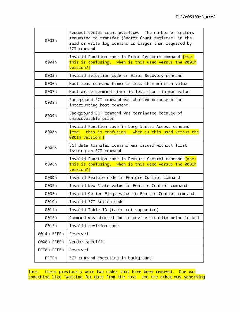
Table 6 – Extended Status codes
Status Code Definition

T13/e05109r3_mer2
[mse: there previously were two codes that have been removed. One was something like “waiting for data from the host” and the other was something like “waiting to send data to the host”. Why were these removed? I think they were useful and would like to see them added back in.]
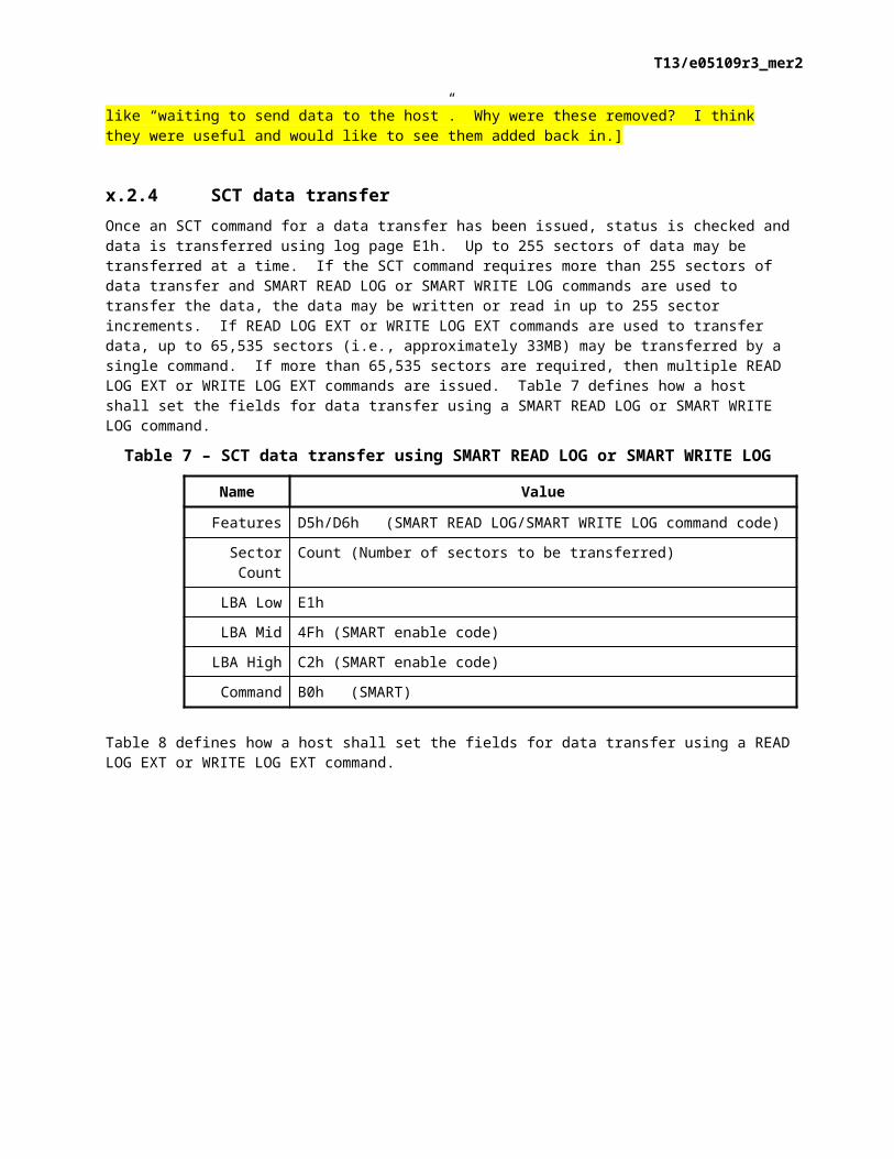
2.4 SCT data transferOnce an SCT command for a data transfer has been issued, status is checked and data is transferred using log page E1h. Up to 255 sectors of data may be transferred at a time. If the SCT command requires more than 255 sectors of data transfer and SMART READ LOG or SMART WRITE LOG commands are used to transfer the data, the data may be written or read in up to 255 sector increments. If READ LOG EXT or WRITE LOG EXT commands are used to transfer data, up to 65,535 sectors (i.e., approximately 33MB) may be transferred by a single command. If more than 65,535 sectors are required, then multiple READ LOG EXT or WRITE LOG EXT commands are issued. Table 7 defines how a host shall set the fields for data transfer using a SMART READ LOG or SMART WRITE LOG command.
Table 7 – SCT data transfer using SMART READ LOG or SMART WRITE LOG
Name Value
Features D5h/D6h (SMART READ LOG/SMART WRITE LOG command code)
Sector Count Count (Number of sectors to be transferred)
LBA Low E1h
LBA Mid 4Fh (SMART enable code)
LBA High C2h (SMART enable code)
Command B0h (SMART)
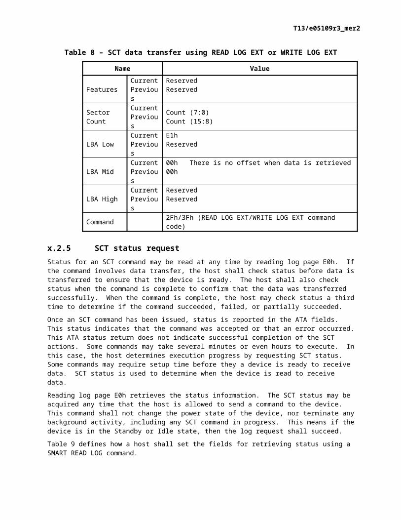
Table 8 defines how a host shall set the fields for data transfer using a READ LOG EXT or WRITE LOG EXT command.
Table 8 – SCT data transfer using READ LOG EXT or WRITE LOG EXT
Name Value
Features CurrentPrevious
ReservedReserved
Sector Count
CurrentPrevious
Count (7:0)Count (15:8)
LBA Low CurrentPrevious
E1hReserved
LBA Mid CurrentPrevious
00h There is no offset when data is retrieved00h
LBA High CurrentPrevious
ReservedReserved
Command 2Fh/3Fh (READ LOG EXT/WRITE LOG EXT command code)

T13/e05109r3_mer2
2.5 SCT status requestStatus for an SCT command may be read at any time by reading log page E0h. If the command involves data transfer, the host shall check status before data is transferred to ensure that the device is ready. The host shall also check status when the command is complete to confirm that the data was transferred successfully. When the command is complete, the host may check status a third time to determine if the command succeeded, failed, or partially succeeded.
Once an SCT command has been issued, status is reported in the ATA fields. This status indicates that the command was accepted or that an error occurred. This ATA status return does not indicate successful completion of the SCT actions. Some commands may take several minutes or even hours to execute. In this case, the host determines execution progress by requesting SCT status. Some commands may require setup time before they a device is ready to receive data. SCT status is used to determine when the device is read to receive data.
Reading log page E0h retrieves the status information. The SCT status may be acquired any time that the host is allowed to send a command to the device. This command shall not change the power state of the device, nor terminate any background activity, including any SCT command in progress. This means if the device is in the Standby or Idle state, then the log request shall succeed.
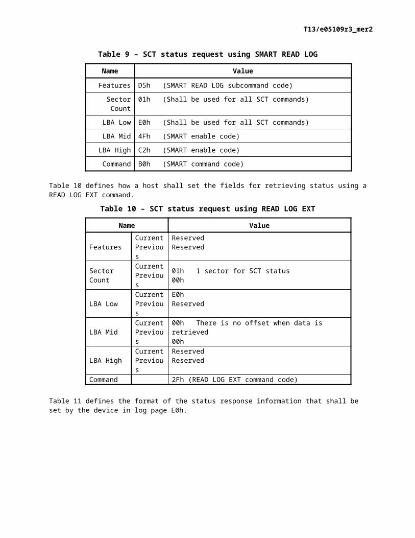
Table 9 defines how a host shall set the fields for retrieving status using a SMART READ LOG command.
Table 9 – SCT status request using SMART READ LOG
Name Value
Features D5h (SMART READ LOG subcommand code)
Sector Count 01h (Shall be used for all SCT commands)
LBA Low E0h (Shall be used for all SCT commands)
LBA Mid 4Fh (SMART enable code)
LBA High C2h (SMART enable code)
Command B0h (SMART command code)
Table 10 defines how a host shall set the fields for retrieving status using a READ LOG EXT command.
Table 10 – SCT status request using READ LOG EXT
Name Value
Features CurrentPrevious
ReservedReserved
Sector Count
CurrentPrevious
01h 1 sector for SCT status00h
LBA Low CurrentPrevious
E0hReserved
LBA Mid CurrentPrevious
00h There is no offset when data is retrieved00h
LBA High CurrentPrevious
ReservedReserved
Command 2Fh (READ LOG EXT command code)
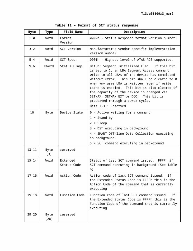
Table 11 defines the format of the status response information that shall be set by the device in log page E0h.
T13/e05109r3_mer2
Table 11 – Format of SCT status responseByte Type Field Name Description
1:0 Word Format Version 0002h - Status Response format version number.
3:2 Word SCT Version Manufacturer’s vendor specific implementation version number
5:4 Word SCT Spec. 0001h - Highest level of ATA8-ACS supported.
9:6 DWord Status Flags Bit 0: Segment Initialized Flag. If this bit is set to 1, an LBA Segment Access command write to all LBAs of the device has completed without error. This bit shall be cleared to 0 when any user LBA is written, even if write cache is enabled. This bit is also cleared if the capacity of the device is changed via SETMAX, SETMAX EXT or DCO. This bit is preserved through a power cycle.Bits 1-31: Reserved
10 Byte Device State 0 = Active waiting for a command1 = Stand-by2 = Sleep3 = DST executing in background4 = SMART Off-line Data Collection executing in background5 = SCT command executing in background
13:11 Byte [3] reserved
15:14 Word Extended Status Code
Status of last SCT command issued. FFFFh if SCT command executing in background (See Table 6).
17:16 Word Action Code Action code of last SCT command issued. If the Extended Status Code is FFFFh this is the Action Code of the command that is currently executing
19:18 Word Function Code Function code of last SCT command issued. If the Extended Status Code is FFFFh this is the Function Code of the command that is currently executing
39:20 Byte [20] reserved
47:40 QWord LBA Current LBA of SCT command executing in background. If there is no command currently executing in the background, this field is undefined.
199:48 Byte [152] reserved 00h
200 Byte HDA Temp Current device HDA temperature in degrees Celsius. This is a 2’s complement number. 80h indicates that this value is invalid.
201 Byte Reserved
202 Byte Max Temp Maximum HDA temperature in degrees Celsius seen this power cycle. This is a 2’s complement number. 80h indicates that this value is invalid.
203 Byte Reserved
T13/e05109r3_mer2
Byte Type Field Name Description
204 Byte Life Max Temp Maximum HDA temperature in degrees Celsius seen for the life of the device. This is a 2’s complement number. 80h indicates that this value is invalid.
479:205 Byte [275] reserved
511:480 Byte [32] Vendor Specific
3 SCT Command SetAn SCT command shall be 512 bytes long. While an SCT command is in progress a host may use an SCT status request to retrieve status information (e.g., to determine if a command active or complete, the current LBA, or error information) about the current SCT command.
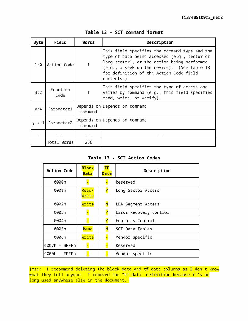
Table 12 defines the generic format of an SCT command written to log page E0h.
Table 12 – SCT command format
Byte Field Words Description
1:0 Action Code 1
This field specifies the command type and the type of data being accessed (e.g., sector or long sector), or the action being performed (e.g., a seek on the device). (See table 13 for definition of the Action Code field contents.)
3:2 Function Code 1 This field specifies the type of access and varies by command (e.g., this field specifies read, write, or verify).
x:4 Parameter1 Depends on command
Depends on command
y:x+1 Parameter2 Depends on command
Depends on command
… ... ... ...
Total Words 256
Table 13 – SCT Action Codes
Action Code Block Data TF Data Description
0000h - - Reserved
0001h Read/Write Y Long Sector Access
0002h Write N LBA Segment Access
0003h - Y Error Recovery Control
0004h - Y Features Control
0005h Read N SCT Data Tables
0006h Write - Vendor specific
0007h - BFFFh - - Reserved
C000h - FFFFh - - Vendor specific
T13/e05109r3_mer2
[mse: I recommend deleting the block data and tf data columns as I don’t know what they tell anyone. I removed the “tf data” definition because it’s no long used anywhere else in the document.]
3.1 Long Sector Access commandThe function performed by the Long Sector Access command is based on the obsolete ATA READ LONG/WRITE LONG capability, and has been extended beyond 28-bit addressing.
The Long Sector data format for both reads and writes is two blocks long (i.e., each block is 512 bytes long). The first block contains the user data. The second data block contains the error correction and detection bytes. The remainder of the second block should contain zeros. Once the SCT command has been issued and the status response indicates that the device is ready to transfer data, log page E1h should be read or written to transfer the data. Long Sector Access commands cause a forced unit access to occur.
Table x.1 [mse: add the proper table name format and add a cross reference here] defines the format of a Long Sector Access command written to log page E0h.
Table x.1 – Long Sector Access commandWord Name Value Description
0 Action Code 0001h Read or Write a sector with full ECC or CRC data
1 Function Code0001h Read Long function
0002h Write Long function
2 LBA QWord Sector to be read or written
Table x.2 [mse: add the proper table name format and add a cross reference here] defines the format of the status response for a Long Sector Access command.
Table x.2 – Long Sector Access command status responseName Value
Error See x.x [mse: add the correct cross reference here.]
Sector Count Low Order number of ECC/CRC bytes
LBA Low High Order number of ECC/CRC bytes
LBA Mid Low 8 bits of number of sectors requested (this shall be two)
LBA High High 8 bits of number of sectors requested (this shall be zero)
Device Reserved
Status See x.x [mse: add the correct cross reference here.]
Table 14 defines the format of the data to be written to log sector E1h for a Long Sector Access command.
T13/e05109r3_mer2
Table 14 – Long Sector Format
Field Size Description
First Block
User Data 512 This is the data normally sent or returned by a read or write command. This data may be encoded.
Second Block
ECC/CRC Data Vendor Specific Error correction and detection bytes in vendor-specific format. The number of bytes is returned as status response data on both read and write operations.
Reserved Remainder of block All zeros
3.2 LBA Segment Access commandThe LBA Segment Access command provides the ability for the host to specify that the device shall write a specific pattern to its media (i.e., perform a “Write All” or “Write Same” function).
The LBA Segment Access command shall cause the device to begin writing sectors from the first sector specified by the command in the Start field (see table x.3 [mse: add the proper table name format and add a cross reference here]) in incrementing order until the number of sectors specified by the command in the Count field (see table x.3 [mse: add the proper table name format and add a cross reference here]) have been written. If the Count field contains all zeros, then the device shall write all sectors beginning with the sector specified by the Start field through the last user LBA on the device. If the Host Protected Area feature set is implemented by and enabled on the device, then this feature set shall determine the last user LBA. This command shall not write over a hidden partition when hidden partitions are enabled using the Host Protected Area feature set. Automatic sector reassignment is permitted during the operation of this function.
If the Start field or the Start field plus the Count field specify an LBA greater than the last user LBA, then the device shall report an error and abort the command. If the Start field and the Count field contain zero, then the device shall write the specified pattern to all user LBAs on the device.
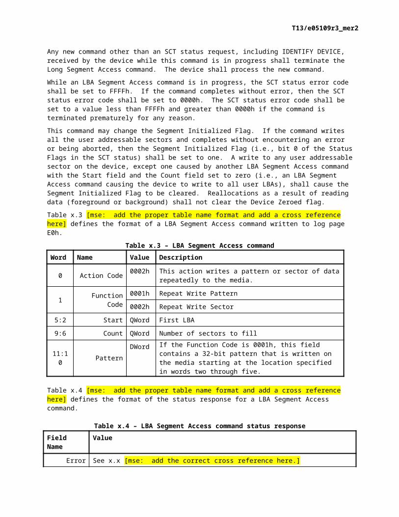
Any new command other than an SCT status request, including IDENTIFY DEVICE, received by the device while this command is in progress shall terminate the Long Segment Access command. The device shall process the new command.
While an LBA Segment Access command is in progress, the SCT status error code shall be set to FFFFh. If the command completes without error, then the SCT status error code shall be set to 0000h. The SCT status error code shall be set to a value less than FFFFh and greater than 0000h if the command is terminated prematurely for any reason.
This command may change the Segment Initialized Flag. If the command writes all the user addressable sectors and completes without encountering an error or being aborted, then the Segment Initialized Flag (i.e., bit 0 of the Status Flags in the SCT status) shall be set to one. A write to any user addressable sector on the device, except one caused by another LBA Segment Access command with the Start field and the Count field set to zero (i.e., an LBA Segment Access command causing the device to write to all user LBAs), shall cause the Segment Initialized Flag to be cleared. Reallocations as a result of reading data (foreground or background) shall not clear the Device Zeroed flag.
Table x.3 [mse: add the proper table name format and add a cross reference here] defines the format of a LBA Segment Access command written to log page E0h.
T13/e05109r3_mer2
Table x.3 – LBA Segment Access commandWord Name Value Description
0 Action Code 0002h This action writes a pattern or sector of data repeatedly to the media.
1 Function Code0001h Repeat Write Pattern
0002h Repeat Write Sector
5:2 Start QWord First LBA
9:6 Count QWord Number of sectors to fill
11:10 PatternDWord If the Function Code is 0001h, this field contains a 32-bit
pattern that is written on the media starting at the location specified in words two through five.
Table x.4 [mse: add the proper table name format and add a cross reference here] defines the format of the status response for a LBA Segment Access command.
Table x.4 – LBA Segment Access command status responseField Name Value
Error See x.x [mse: add the correct cross reference here.]
Sector Count Reserved
LBA Low Reserved
LBA Mid Low 8 bits of number of sectors requested (this shall be one)
LBA High High 8 bits of number of sectors requested (this shall be zero)
Device Reserved
Status See x.x [mse: add the correct cross reference here.]
3.3 Error Recovery Control commandThe Error Recovery Control command is used to set time limits for read and write error recovery. For non-queued commands, these timers apply to command completion at the host interface. For queued commands where in-order data delivery is enabled, these timers begin counting when the device begins to execute the command, not when the command is sent to the device. These timers do not apply to streaming commands or to queued commands when out-of-order data delivery is enabled. Time limits for error recovery may be used in a data redundant RAID environment where it is more desirable to have the device report a data error rather than risk having it being dropped from the RAID.
The typical usage for this command is when an ATA or SATA device has its write cache function enabled. With write cache enabled, the device cannot report an error on a write command. This is because the write command with which a device is experiencing difficulty is one for which the device has reported status (i.e., considered by the host to be complete). This leaves no recourse for the device other than to reallocate any sectors with which it is experiencing difficulty.
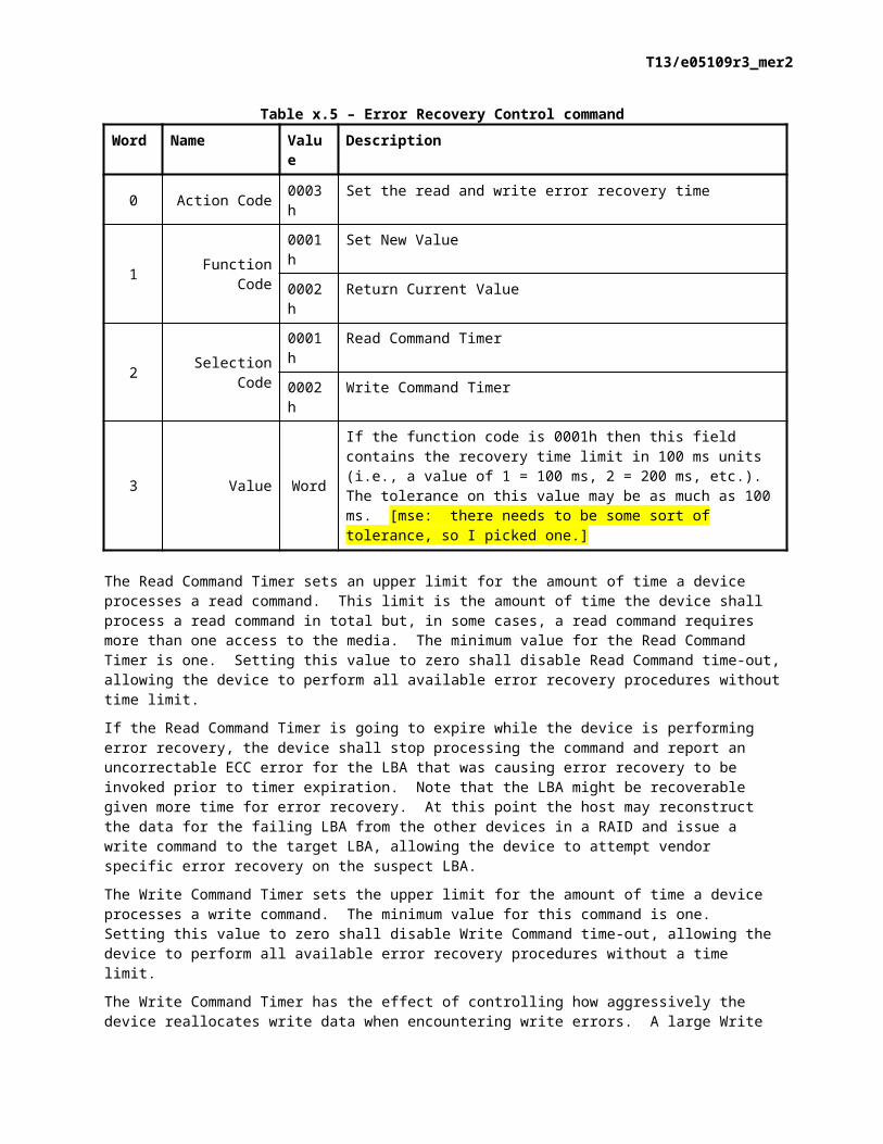
Table x.5 [mse: add the proper table name format and add a cross reference here] defines the format of an Error Recovery Control command written to log page E0h.

T13/e05109r3_mer2
Table x.5 – Error Recovery Control commandWord Name Value Description
0 Action Code 0003h Set the read and write error recovery time
1 Function Code0001h Set New Value
0002h Return Current Value
2 Selection Code0001h Read Command Timer
0002h Write Command Timer
3 Value Word
If the function code is 0001h then this field contains the recovery time limit in 100 ms units (i.e., a value of 1 = 100 ms, 2 = 200 ms, etc.). The tolerance on this value may be as much as 100 ms. [mse: there needs to be some sort of tolerance, so I picked one.]
The Read Command Timer sets an upper limit for the amount of time a device processes a read command. This limit is the amount of time the device shall process a read command in total but, in some cases, a read command requires more than one access to the media. The minimum value for the Read Command Timer is one. Setting this value to zero shall disable Read Command time-out, allowing the device to perform all available error recovery procedures without time limit.
If the Read Command Timer is going to expire while the device is performing error recovery, the device shall stop processing the command and report an uncorrectable ECC error for the LBA that was causing error recovery to be invoked prior to timer expiration. Note that the LBA might be recoverable given more time for error recovery. At this point the host may reconstruct the data for the failing LBA from the other devices in a RAID and issue a write command to the target LBA, allowing the device to attempt vendor specific error recovery on the suspect LBA.
The Write Command Timer sets the upper limit for the amount of time a device processes a write command. The minimum value for this command is one. Setting this value to zero shall disable Write Command time-out, allowing the device to perform all available error recovery procedures without a time limit.
The Write Command Timer has the effect of controlling how aggressively the device reallocates write data when encountering write errors. A large Write Command Timer value allows the device to use more available error recovery procedures for dealing with write errors. A small Write Command Timer value forces the device to attempt to reallocate sectors that may have otherwise been written without error. If the timer is about to expire, then the device should attempt to reallocate the data before the timer expires. If the device is unable to complete data reallocation before the timer expires then the devices fails the command when the timer expires. When write cache is enabled the operation of the timer is vendor specific.
A host implementer should use the Write Command Timer with great caution as a very small timer value could cause a device to permanently reallocate good sectors as the result of temporary, external conditions (e.g., induced vibration).
[mse: I added the big caveat above as I think this is a dangerous feature. I would much rather have a device abort the command like we do in SCSI – and for the Read Command Timer.]
Read and Write Command Timer values are set to default values at power-on but may be altered by an SCT command at any time. These settings are unaffected by software (soft) or hardware (pin 1 or COMRESET) reset.
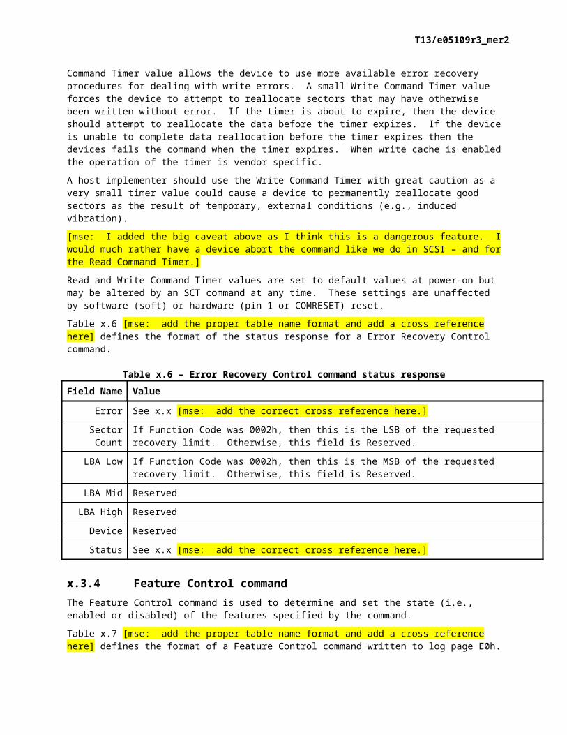
Table x.6 [mse: add the proper table name format and add a cross reference here] defines the format of the status response for a Error Recovery Control command.
T13/e05109r3_mer2
Table x.6 – Error Recovery Control command status responseField Name Value
Error See x.x [mse: add the correct cross reference here.]
Sector Count If Function Code was 0002h, then this is the LSB of the requested recovery limit. Otherwise, this field is Reserved.
LBA Low If Function Code was 0002h, then this is the MSB of the requested recovery limit. Otherwise, this field is Reserved.
LBA Mid Reserved
LBA High Reserved
Device Reserved
Status See x.x [mse: add the correct cross reference here.]
3.4 Feature Control commandThe Feature Control command is used to determine and set the state (i.e., enabled or disabled) of the features specified by the command.
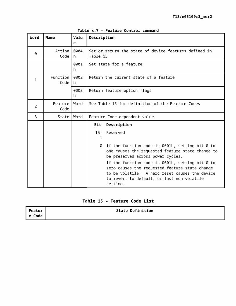
Table x.7 [mse: add the proper table name format and add a cross reference here] defines the format of a Feature Control command written to log page E0h.
Table x.7 – Feature Control commandWord Name Value Description
0 Action Code 0004h Set or return the state of device features defined in Table 15
1 Function Code
0001h Set state for a feature
0002h Return the current state of a feature
0003h Return feature option flags
2 Feature Code Word See Table 15 for definition of the Feature Codes
3 State Word Feature Code dependent value
Bit Description
15:1 Reserved
0 If the function code is 0001h, setting bit 0 to one causes the requested feature state change to be preserved across power cycles.If the function code is 0001h, setting bit 0 to zero causes the requested feature state change to be volatile. A hard reset causes the device to revert to default, or last non-volatile setting.
Table 15 – Feature Code List
Feature Code
State Definition

T13/e05109r3_mer2
0001h If State is set to 0001h, then the SET FEATURES command shall determine the state of write cache (see x.x [mse: add the correct cross reference here.]).If State is set to 0002h, then write cache shall be enabled.If State is set to 0003h, then write cache shall be disabled.If State is set to 0002h or 0003h, then write cache shall be set to the specified state, and any attempt to change the write cache settings using a SET FEATURES command shall not result in an error but shall not change the operational state of the write cache.In all cases, bit 5 of word 85 in the IDENTIFY DEVICE information shall reflect the current operational state of write cache (i.e., if set to one, then write cache is enabled, and if set to zero, then write cache is disabled.The default is State set to 0001h.
0002h If State is set to 0001h, then Write Cache Reordering shall be enabled (i.e., disk write scheduling may be reordered by the device).If State is set to 0002h, then Write Cache Reordering shall be disabled, and disk write scheduling is executed on a first-in-first-out (FIFO) basis.If write cache is disabled, then the current Write Cache Reordering state is remembered but has no effect on non-cached writes, which are always written in the order received.The state of Write Cache Reordering has no effect on queued commands.The default is State set to 0001h.
0003h The value in State sets the time interval for temperature logging.State set to 0000h is invalid [mse: is this an error?]State may be set to 0001h to FFFFh to specify the temperature logging interval in minutesThis value applies to the Absolute HDA Temperature History queue. Issuing this command shall cause the queue to be reset and any prior values in the queues shall be lost. Queue Index shall be set to zero and the first queue location for shall be set to the current value. All remaining queue locations are set to 80h. The Sample Period, Max Op Limit, Over Limit, Min Op Limit and Under Limit values are preserved. (See Table 17.)The default is State set to 0001h.
0004h – CFFFh
Reserved
D000h - FFFFh
Vendor Specific
Table x.8 [mse: add the proper table name format and add a cross reference here] defines the format of the status response for a Feature Control command.
Table x.8 – Feature Control command status responseField Name Value
Error See x.x [mse: add the correct cross reference here.]
Sector Count If the Function Code was set to 0002h this is the Feature State LSBIf the Function Code was set to 0003h this is the Option Flags LSBOtherwise this field is Reserved
LBA Low If the Function Code was set to 0002h this is the Feature State MSBIf the Function Code was set to 0003h this is the Option Flags MSBOtherwise this field is Reserved

T13/e05109r3_mer2
LBA Mid Reserved
LBA High Reserved
Device Reserved
Status See x.x [mse: add the correct cross reference here.]
3.5 SCT Data Table commandThe SCT Data Table command is used to read the specified data table.
Table x.9 [mse: add the proper table name format and add a cross reference here] defines the format of an SCT Data Table command written to log page E0h.
Table x.9 – SCT Data Table commandWord Name Value Description
0 Action Code 0005h Read a data table
1 Function Code 0001h Read Table
2 Table ID Word See Table 16 for a list of data tables
Table 16 – SCT Data Tables (by Table Identifier)
Table Id Description
0000h Invalid
0001h Reserved
0002h HDA Temperature History Table (in absolute degrees C). (See Table 17)
0003h - CFFFh Reserved
D000h - FFFFh Vendor Specific
Table 17 – Absolute HDA Temperature
Byte Size Field Name Description
1:0 Word Format Version 0002h - Data table format version
3:2 Word Sampling Period
Absolute HDA Temperature sampling period in minutes. This is how often the device samples its temperature sensor. This period takes precedence over new read or write operations, but does not interrupt operations in process.The Sampling Period may be smaller that the timer interval between entries in the history queue.A value of 0000h in this field indicates that sampling is disabled.
5:4 Word Interval The timer interval between entries in the history queue. The default value of this field is vendor specific. This value should not be less than the Sampling Period.
6 Byte Max Op LimitMaximum recommended continuous operating temperature (see Note 3). This is a one byte two’s complement number that allows a range from -127 °C to +127 °C to be indicated. 80h is an invalid value. This is a fixed value.
T13/e05109r3_mer2
Byte Size Field Name Description
7 Byte Over Limit
Maximum temperature limit. Operating the device above this temperature may cause physical damage to the device (see Note 3). This is a one-byte two’s complement number that allows a range from -127 °C to +127 °C to be indicated. 80h is an invalid value. This is a fixed value.
8 Byte Min Op LimitMinimum recommended continuous operating limit (see Note 3). This is a one byte 2’s complement number that allows a range from -127 °C to +127 °C to be indicated. 80h is an invalid value. This is a fixed value.
9 Byte Under Limit
Minimum temperature limit. Operating the device below this temperature may cause physical damage to the device (see Note 3). This is a one-byte two’s complement number that allows a range from -127 °C to +127 °C to be indicated. 80h is an invalid value. This is a fixed value.
29:10 Byte [20] reserved
31:30 Word Queue Size Number of entry locations in history queue. This number shall be in the range of 128 to 478.
33:32 Word Queue IndexLast updated entry in queue. Queue Index is zero-based, so Queue Index 0000h is the first location in the buffer (i.e., at offset 34). The most recent temperature entered in the buffer is at Queue Index + 34 (see Notes 1 and 2).
Queue Size + 33:34
Byte [Queue Size]
Queue Buffer
This is a circular buffer of absolute HDA Temperature values. Other device activities, such as data transfer, take priority over writing this data to non-volatile storage. These are one-byte two’s complement numbers that allow a range from -127 °C to +127 °C to be indicated. A value of 80h indicates an initial value or a discontinuity in temperature recording.The time between samples may vary because commands shall not be interrupted. The sampling period is the minimum time between samples (see Note 1).If the host changes the logging interval using the volatile option, then the interval between entries in the queue may change between power cycles with no indication to the host.
511:Queue Size+ 34
Byte[512 -Queue Size - 34]
reserved Shall be zero.
Note 1 - The Absolute HDA Temperature History is preserved across power cycles with the requirement that when the device powers up, a new entry is made in the history queue with a value of 80h (i.e., an invalid absolute temperature value). This allows an application viewing the history to see the discontinuity in temperature resulting from the device being turned off. If the device does not sample temperatures during a certain power state (e.g., Sleep or Standby), then a value of 80h is entered into the history queue to indicate that temperature sensing has resumed.Note 2 - When the Absolute HDA Temperature history is cleared (e.g., for new devices or after changing the Logging Interval) the Queue Index shall be set to zero and the first queue location shall be set to the current Absolute HDA Temperature value. All remaining queue locations shall be set to 80h.Note 3 - These values should take into account the accuracy of the temperature sensor. The placement, accuracy, and granularity of temperature sensors to support Table 17 are vendor specific.
Table x.10 [mse: add the proper table name format and add a cross reference here] defines the format of the status response for an SCT Data Table command.

T13/e05109r3_mer2
Table x.8 – Feature Control command status responseField Name Value
Error See x.x [mse: add the correct cross reference here.]
Sector Count Reserved
LBA Low Reserved
LBA Mid Low 8 bits of number of sectors remaining (this shall be one)
LBA High High 8 bits of number of sectors remaining (this shall be zero)
Device Reserved
Status See x.x [mse: add the correct cross reference here.]
3. Add the following informative annex:
Annex n -- How to use SCT commands
(Informative)
x How to use SCT commands overviewSCT commands piggy-back on the standard ATA commands: SMART READ LOG and SMART WRITE LOG, or READ LOG EXT and WRITE LOG EXT. As viewed through an ATA protocol analyzer, an SCT command is seen as data being transferred by these commands; whereas from the perspective of a device that implements this feature set, this “data” would be interpreted as an SCT command request, an SCT command response, SCT command status, or SCT command data.
Figure a [mse: add the proper figure name format and add a cross reference here] is an example flowchart that shows how to process SCT commands using SMART READ LOG and SMART WRITE LOG commands:
T13/e05109r3_mer2
Figure a – Example flowchart for SCT commands
T13/e05109r3_mer2
1 Examples of Log page command sequencesFigure 1 shows an example command sequence for writing data to a device using an SCT command with no background activity.
Figure 1 – Example sequence for writing data using an SCT command with no background activity
Figure 2 shows an example command sequence for reading data from a device using an SCT command with no background activity.
Figure 2 – Example sequence for reading data using an SCT command with no background activity
Figure 3 shows an example command sequence for issuing a Log page command that does not transfer data and has no background activity.
Figure 3 – Example Sequence for a non-datan SCT command with no background activityFigure 4 shows an example command sequence for issuing an SCT command that writes data in the background.
T13/e05109r3_mer2
Figure 4– Example sequence for writing data using an SCT command with background activity
Figure 5 shows an example command sequence for issuing an SCT command that executes in the background but does not require the transfer of data to or from the host.

T13/e05109r3_mer2
Figure 5 – Example sequence for a non-datan SCT command with background activity
2 Issuing an SCT command to a device2.1 Step 1 - Build a Key SectorThe host builds the key sector in a host buffer for the appropriate action and parameters.
2.2 Step 2 - Issue the SCT commandThe host issues the SCT command (see Table 18 or Table 19, and sends the key sector to the device.
Table 18 – SCT command using SMART WRITE LOG command
Register Value
Features D6h (SMART WRITE LOG subcommand code)
Sector Count 01h (Shall always be 01h)
LBA Low E0h (Command port)
LBA Mid 4Fh (SMART enable code)
LBA High C2h (SMART enable code)
Command B0h (SMART)

T13/e05109r3_mer2
Table 19 – SCT command using WRITE LOG EXT command
Register Value
Features CurrentPrevious
ReservedReserved
Sector Count
CurrentPrevious
01h 1 sector for SCT commands00h
LBA Low CurrentPrevious
E0hReserved
LBA Mid CurrentPrevious
00h There is no offset when commands are issued00h
LBA High CurrentPrevious
ReservedReserved
Command 3Fh (WRITE LOG EXT)
The device responds with successful status (see Table 4). If the command is aborted (i.e., Status = 51h and Error = 04h), then either the key sector format is invalid, the task file contains an invalid value or the command encountered an execution error. The host checks the Sector Count and LBA Low registers for the error code (see Table 5 and Table 6). If the command was a “write” command, the command is terminated, there is no data transfer, and the host skips Step 3. However, if the command was a “read” command, there maybe partial output available. For example, on a sector read command, the data up to and including the sector in error is available. In this case, the host may proceed to Step 3 to get the partial data. In certain cases the error is not fatal and serves only as a warning.
If the status is 50h, then the host checks the LBA Mid and LBA High fields. If the values are 0, then the command is complete, terminated without error, and the host proceeds to Step 4. If the values are greater than 0, then the host proceeds to Step 3.
2.3 Step 3 - Transfer Data if RequiredTo transfer data from the device to the host, the host issues a SMART READ LOG or READ LOG EXT command to address E1h (see Table 7 and Table 8). To transfer data from the host to the device, the host issues a SMART WRITE LOG or WRITE LOG EXT command to address E1h (See Table 7 and Table 8). The transfer request is in the range of 1 sector up to the total number of sectors not yet transferred. The number of sectors remaining was posted in the LBA Mid and LBA High registers in the previous step. If the requested number of sectors is larger than the number of the sectors remaining, the device reports an error. If the value is less then the number of sectors remaining, the host may repeat Step 3 until all sectors have been transferred.
For SCT commands that access the media, the device advances the sector pointer by the number of sectors transferred, and reports in the LBA Mid and LBA High registers the number of sectors remaining to be transferred. If both registers contain zero, then the command is complete, and the host proceeds to Step 4. The host has complete control over the number of sectors to transfer at a time. Note, if the number of sectors to be transferred is greater or equal to FFFFh, the device sets the LBA Mid and High fields to FFFFh. The value remains FFFFh until the number of sectors remaining drops below FFFFh. The exact number to be transferred is reported by the SCT Status command. Upon receiving the last block of data, the device performs the specified operation. In the case of very large amounts of data, such as LBA Segment Access, some data may be processed (e.g., written to the disk) prior to receiving all of the data from the host.
2.4 Step 4 - Final Status/SCT Command CompletionThe host reads the SCT status response (See Table 9, Table 10, and Table 11) to determine how the command completed. If the command has not completed (i.e., by reporting FFFFh in Table 11 byte 14) then the host waits for some period of time and repeats Step 4 until the command is complete. For SCT

T13/e05109r3_mer2
commands that require transfer of data to the device (e.g., a write command), the command is not complete until the last block of data has been transferred to the device.