proposals for iram telescopes · normal proposals should not exceed 6 pages, except ... the four...
TRANSCRIPT
1
Proposals for IRAM Telescopes
The deadline for submission of observing proposalson IRAM telescopes, both the interferometer andthe 30m, is
12 March 2009, 17:00 CET (UT + 1 hour)
The scheduling period extends from 1 June – 30 Nov2009. Proposals should be submitted through ourweb–based submission facility. Instructions can befound on our web page at URL:
http://www.iram.fr/GENERAL/submission/submission.html
Detailed information on time estimates, special ob-serving modes, technical information and referencesfor both the IRAM interferometer and the IRAM30m telescope can be found on the above mentionedweb page. The submission facility will be openedabout three weeks before the proposal deadline. Pro-posal form pages and the 30m time estimator areavailable now.
Please avoid last minute submissions when thenetwork could be congested. As an insurance againstnetwork congestion or failure, we still accept, in welljustified cases, proposals submitted by:
– fax to number: (+33) 476 42 54 69 or by
– ordinary mail addressed to:IRAM Scientific Secretariat,300, rue de la piscine,F-38406 St. Martin d’Heres, France
Proposals sent by e–mail are not accepted. Colorplots will be printed/copied in grey scale. If coloris considered essential for the understanding of aspecific figure, a respective remark should be addedin the figure caption. The color version may then beconsulted in the electronic proposal by the referees.
Soon after the deadline the IRAM Scientific Sec-retariat sends an acknowledgement of receipt to thePrincipal Investigator of each proposal correctly re-ceived, together with the proposal registration num-ber. Note that the web facility allows cancellationand modification of proposals before the deadline.The facility also allows to view the proposal in its fi-nal form as it appears after re–compilation at IRAM.We urge proposers to make use of this feature as wealways receive a number of corrupted proposals (fig-ures missing, blank pages, etc.).
Valid proposals contain the official cover page, oneor more pages of technical information, up to twopages of text describing the scientific aims, and upto two more pages of figures, tables, and references.Normal proposals should not exceed 6 pages, exceptfor additional technical pages. Longer proposals will
be cut. We continue to call for Large Observ-
ing Programmes as described by P. Cox in thisNewsletter. The Large Programmes may have upto 4 pages for the scientific justification, plus coverpage, the technical pages, and 2 pages for supportingmaterial.
Both proposal forms, for the 30m telescope andfor the interferometer, have been changed consid-erably for the current deadline. In fact, we nowhave different template files for the two telescopes,prop-pdb.tex and prop-30m.tex. Please, make
absolutely sure to use the current version
of these files and the common LATEX style fileproposal.sty. All three files may be downloadedfrom the IRAM web pages1 at URL ../GENERAL/-
submission/proposal.html. Do not change thefont type or size, and do not manipulate the stylefile. In case of problems, contact the IRAM secre-tary. (e–mail: [email protected]).
In all cases, indicate on the proposal cover pagewhether your proposal is (or is not) a resubmissionof a previously rejected proposal or a continuationof a previously accepted interferometer or 30m pro-posal. We request that the proposers describe verybriefly in the introductory paragraph (automaticallygenerated header “Proposal history: ”) why the pro-posal is being resubmitted (e.g. improved scientificjustification) or is proposed to be continued (e.g. lastobservations suffered from bad weather).
Short spacing observations on the 30m tele-scope can now be requested directly on the interfer-ometer proposal form. A separate proposal for the30m telescope is not required. The interferometerproposal form contains a bullet, labelled “short spac-ings” which should then be checked. The user will beprompted to fill in an additional paragraph in whichthe scientific need for the short spacings should bedescribed. It is essential to give here all observationaldetails, including size of map, sampling density andrms noise, spectral resolution, receiver configurationand time requested.
A mailing list has been set up for astronomersinterested in being notified about the availability ofa new Call for Proposals. A link to this mailing list ison the IRAM web page. The list presently containsall users of IRAM telescopes during the last 2 years.
J.M. Winters & C. Thum
1 from here on we give only relative URL addresses. In theabsolute address the leading two dots (..) should be replacedby the address of one of our mirror sites: http://www.iram.fror http://www.iram.es.

2 CALL FOR OBSERVING PROPOSALS ON THE 30M TELESCOPE
Travel funds for European
astronomers
The European Framework Programme 6 (FP 6)which includes the RadioNet initiative has come toan end in 2008. In FP 7, a new RadioNet initia-tive has been accepted in which IRAM is involvedwith its two Observatories. A budget similar to the2004 – 2008 period will be available for supportingtravel by European astronomers through the TransNational Access (TNA) Programme.
As before, travel may be supported to the 30mtelescope and to Grenoble for reduction of inter-ferometer data. Detailed information about the el-igibility, TNA contacts, policies, and travel claimscan be found on the RadioNet home page athttp://www.radionet-eu.org. The Principal Investi-gators of IRAM proposals eligible for TNA fundingwill be contacted as soon as the new Radionet pro-gramme has officially started and the correspondingfunds are available.
R. Neri & C. Thum
Call for Observing Proposals on
the 30m Telescope
Summary
Proposals for three types of receivers will be con-sidered for this summer semester (1 June – 30 Nov2009):
1. the new four band receiver EMIR consisting ofdual–polarization mixers operating at 3, 2, 1.3,and 0.9mm.
2. the 9 pixel dual–polarization heterodyne re-ceiver array, HERA, operating at 1.3 mm wave-length.
3. The MAMBO-2 bolometer array with 117 pix-els operating at 1.2 mm.
About 2000 hours of observing time are expectedto be available. The emphasis will be put on ob-servations at the longer wavelengths. The bulk ofthe 1.3mm observations will be scheduled in Oc-tober/November. Proposals for the 0.9mm band ofEMIR will not be considered for this deadline. Aseparate Call for 0.9mm Proposals may be is-sued in May when the commissioning results for thishighly weather dependent band will be available.
We continue to call for Large Programmes whichmay consider using HERA and MAMBO as well as
the new receiver EMIR with the exception of its0.9mm band (see contribution by P. Cox elsewherein this Newsletter).
What is new?
EMIR The new generation single pixel het-erodyne receiver for Pico Veleta, EMIR (EightMIxer Receiver), consisting of dual-polarization 4GHz bandwidth mixers operating at 3, 2, 1.3, and0.9mm, will be installed and commissioned duringMarch/April 2009. During a large part of the fiveweeks installation and commissioning period, pooledobservations will be made during night time.
EMIR not only provides large improvements inreceiver noise temperature and bandwidth, it is alsomore complex than the old receivers. We thereforeurge interested users to carefully study the detaileddescription below.
Observation time estimator We have prepareda new 30m time estimator for EMIR. Starting withthe feb02b release, it is part of the GILDAS soft-ware and accessible only via ASTRO. For down-loading of the GILDAS package please go to theGILDAS web site and follow the instructions. Notethat a web based estimator for EMIR will be madeavailable only for the next deadline in September 09.As for HERA and MAMBO, the old web based timeestimator is still available here.
Proposal form. Motivated by the arrival ofEMIR, the proposal form for the 30m telescope hasbeen modified. It now collects the technical param-eters of the requested observations in more detailon a separate technical sheet which is printed as thesecond page of the proposal. Note that the 30m tele-scope and the interferometer now have separate pro-posal templates.
In the following, we present the new receiverEMIR. The bolometer and HERA which continueto be operational as before are described in the fullversion of the Call for Porposals available on theIRAM web site.
EMIR
Overview
The new receiver EMIR (Fig. 1) is scheduled for in-stallation and commissioning at the 30m telescopein March through April 2009. EMIR will replace thecurrent single pixel heterodyne receivers A/B100,
EMIR 3
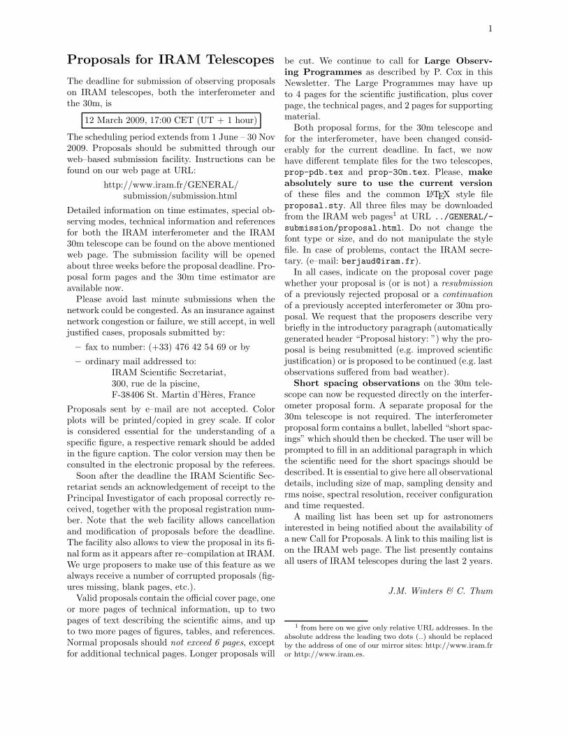
Figure 1: EMIR during final integration in theGrenoble receiver laboratory. One of the four dual–polarization mixer pairs is visible near the centerof the photograph. The beams of the 4 mixer pairsleave the dewar through 4 separate windows towardsthe top of the figure. Warm optics (not shown) cancombine some of the 4 beams for observation of thesame position on the sky (see Tab. 1).
C/D150, A/B230, and C/D270. HERA, the bolome-ters, and the backends are unchanged. EMIR willprovide a minimum instantaneous bandwidth of 4GHz in each of the two orthogonal linear polar-izations for the 3, 2, 1.3 and 0.9mm atmosphericwindows (Fig. 2). In addition to the vast increasein bandwidth compared to the old single pixel re-ceivers, EMIR is expected to offer significantly im-proved noise performance, a stable alignment be-tween bands, and other practical advantages.
The four EMIR bands are designated as E090,E150, E230, and E330 according to their approx-imate center frequencies in GHz. While the E150and E230 bands have SSB mixers with a single side-band available at a time, the E 090 and E330 bandsare operated in 2SB mode where both sidebands areavailable for connection to backends. Furthermore,the E090 band uses a technology that offers 8 GHzinstantaneous bandwidth per sideband and polariza-tion. Both polarizations of a given band will always
be tuned to the same frequency as they share a singlecommon local oscillator. The tuning ranges of the 4bands, the typical receiver noise temperatures, andother parameters as measured in the lab are listedin Tab. 1.
For the first time in the history of the 30mtelescope, EMIR will provide a permanently avail-able high sensitivity E330 band, opening this atmo-spheric window for regular use under good weatherconditions. However, as commissioning of this bandwill be difficult and time consuming during the sum-mer semester, we do not offer the 0.9mm band rightnow. A separate Call for 0.9mm observations maybe issued in May in case that commissioning of thisband came to a positive conclusion.
At the time of writing, EMIR is undergoing fi-nal tests in the receiver laboratory. Precise fig-ures of EMIR’s performance at the telescope willnot be known before the proposal deadline. TheObservatory will make the results of the commis-sioning available as soon as possible on the 30mweb site. The interested astronomer may also findmore detailed technical information on EMIR underthis URL. IRAM staff is also be available to helpastronomers with the preparation of EMIR (andother) proposals.
Selection of EMIR bands
Before reaching the Nasmyth mirrors, the fourbeams of the EMIR bands pass through warm op-tics that contains switchable mirrors and dichroicelements for redirection of the beams towards cali-bration loads and for combining beams. In its sim-plest mode, the warm optics unit selects one singleEMIR band for observation. This mode avoids theuse of the slightly lossy dichroic elements and there-fore offers the best receiver noise temperatures.
Three dichroic mirrors are available for combin-ing either the E 090 and E150 beams, or the E090and E230 beams, or the E150 and E330 beams(Tab. 1). The combination of bands is not polar-ization selective, i.e. the combined bands will staydual polarization. The loss of these dichroics whichis small over most of the accessible frequency range,increases however the receiver temperatures by 10 –15 K. The observer is therefore adviced to carefullyevaluate whether an observation involving two dif-ferent bands is more efficiently made in parallel orin series.
4 CALL FOR OBSERVING PROPOSALS ON THE 30M TELESCOPE
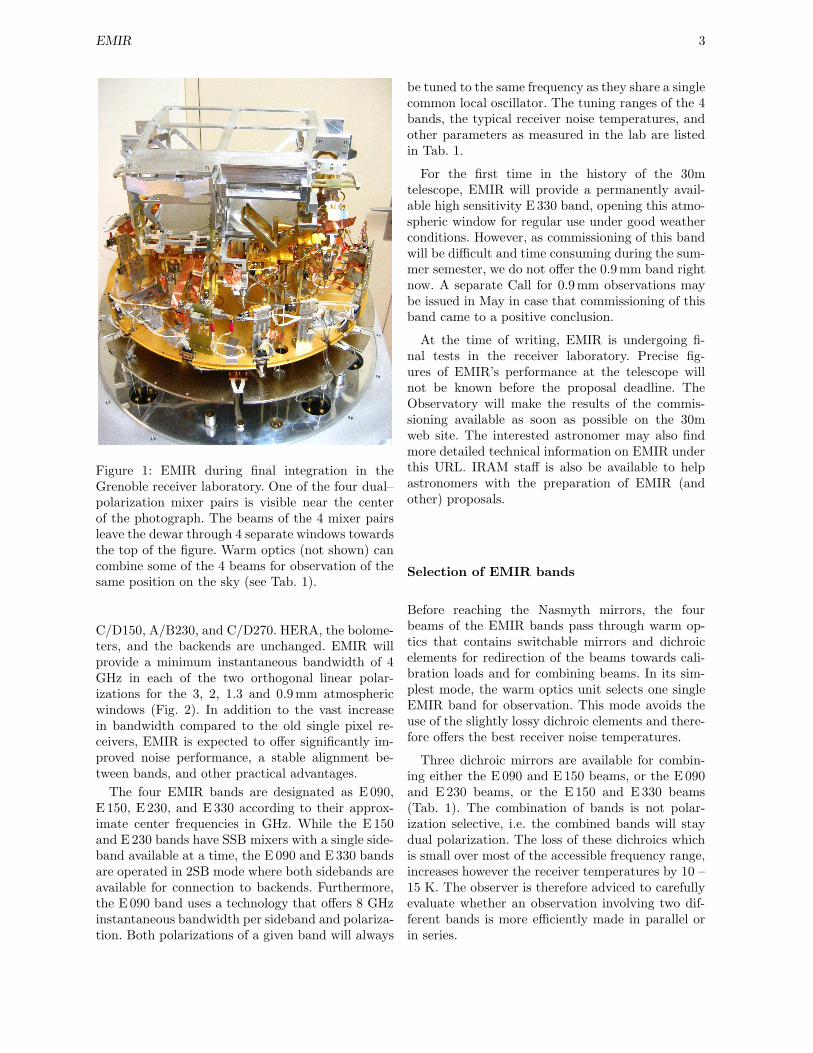
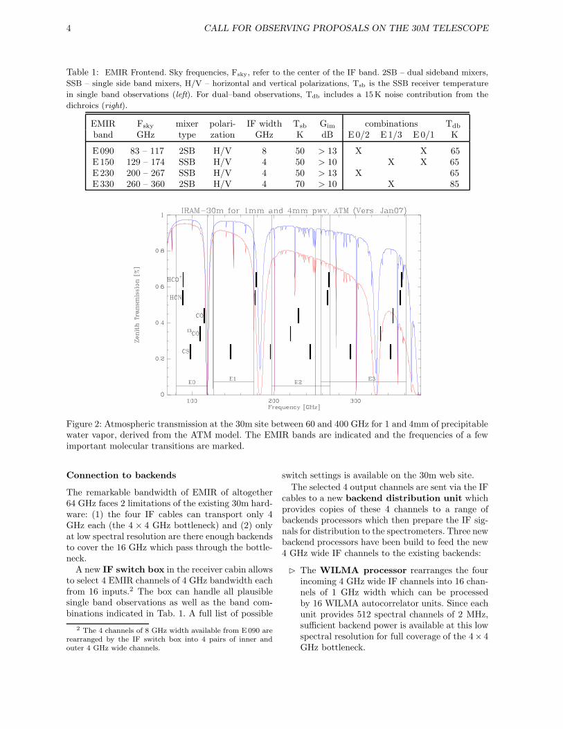
Table 1: EMIR Frontend. Sky frequencies, Fsky, refer to the center of the IF band. 2SB – dual sideband mixers,
SSB – single side band mixers, H/V – horizontal and vertical polarizations, Tsb is the SSB receiver temperature
in single band observations (left). For dual–band observations, Tdb includes a 15 K noise contribution from the
dichroics (right).
EMIR Fsky mixer polari- IF width Tsb Gim combinations Tdb
band GHz type zation GHz K dB E0/2 E 1/3 E0/1 K
E090 83 – 117 2SB H/V 8 50 > 13 X X 65E150 129 – 174 SSB H/V 4 50 > 10 X X 65E230 200 – 267 SSB H/V 4 50 > 13 X 65E330 260 – 360 2SB H/V 4 70 > 10 X 85
Figure 2: Atmospheric transmission at the 30m site between 60 and 400 GHz for 1 and 4mm of precipitablewater vapor, derived from the ATM model. The EMIR bands are indicated and the frequencies of a fewimportant molecular transitions are marked.
Connection to backends
The remarkable bandwidth of EMIR of altogether64 GHz faces 2 limitations of the existing 30m hard-ware: (1) the four IF cables can transport only 4GHz each (the 4 × 4 GHz bottleneck) and (2) onlyat low spectral resolution are there enough backendsto cover the 16 GHz which pass through the bottle-neck.
A new IF switch box in the receiver cabin allowsto select 4 EMIR channels of 4 GHz bandwidth eachfrom 16 inputs.2 The box can handle all plausiblesingle band observations as well as the band com-binations indicated in Tab. 1. A full list of possible
2 The 4 channels of 8 GHz width available from E 090 arerearranged by the IF switch box into 4 pairs of inner andouter 4 GHz wide channels.
switch settings is available on the 30m web site.
The selected 4 output channels are sent via the IFcables to a new backend distribution unit whichprovides copies of these 4 channels to a range ofbackends processors which then prepare the IF sig-nals for distribution to the spectrometers. Three newbackend processors have been build to feed the new4 GHz wide IF channels to the existing backends:
The WILMA processor rearranges the fourincoming 4 GHz wide IF channels into 16 chan-nels of 1 GHz width which can be processedby 16 WILMA autocorrelator units. Since eachunit provides 512 spectral channels of 2 MHz,sufficient backend power is available at this lowspectral resolution for full coverage of the 4× 4GHz bottleneck.

Receivers 5
The 4 MHz processor rearranges any two in-coming 4 GHz wide IF channels into 8 slices of1 GHz width for processing in 8 units of the 4MHz filter bank. 2×4 GHz of EMIR bandwidthare thus covered at 4 MHz resolution.
The “narrow band backends” processor
prepares the 4 incoming IF channels for inputinto the 1 MHz filterbank and VESPA. Onlythe central part of the 4 GHz IF channels isaccessible to these backends. Inside this centralpart (1 GHz for the filterbank and 640 MHz forVESPA), these backends can be configured asbefore. The VLBI terminal is also fed from thisprocessor.
Calibration Issues
EMIR comes with a new calibration system. Theexternal warm optics provides ambient temperatureloads and mirrors reflecting the beams back onto the15 K stage of the cryostat. This system is expectedto be very reliable and constant over time. Absolutecalibration accuracy will be better than 10% withEMIR when all details are well settled.
Bands E150 and E230 have backshort tunedsingle–sideband mixers; DSB tuning is not possi-ble, but sidebands (USB or LSB) may be selectablewithin limitations. The image rejection is betterthan 10 dB for all frequencies. On–site measure-ments of the rejection is not longer straightforwardfor these mixers, since the Martin–Puplett interfer-ometers are not available anymore. As the optimumway of calibrating the image rejection is still understudy, users who propose observations which rely onan enhanced accuracy of calibration of image gainsshould mention this request in the proposal.
Bands E 090 and E330 have tunerless sidebandseparation mixers, allowing simultaneous observa-tions of both sidebands in separate IF bands. Thesemixers have been characterized in the laboratory fortheir image rejection and are expected to have thesame performance on site (> 13 dB).
Velocity scales
It is common practice at radio observatories to cor-rect the frequency of an observation for the stronglytime variable velocity of the Observatory with re-spect to the solar system barycenter. This guaran-tees that lines observed near the Doppler–trackedfrequency, usually the band center, always have thecorrect barycentric velocity, independent of the timeof observation. However, the effect of the Obser-vatory’s motion on the velocity scale which affects
most the velocity channels farthest away from theDoppler–tracked frequency, is usually ignored.
This effect which is of the order of 10−4 cannot beneglected anymore if large bandwidths are used, aswith EMIR. The worst case occurs with band E090where channels as far away as 20 GHz need to beconsidered if a velocity channel in one of the side-bands is Doppler–tracked. In unfavorable but nev-ertheless frequent cases (target source not too farfrom the ecliptic, like the Galactic center), errors ofup to ±2 MHz occur. Since the magnitude of theerror changes with time, narrow spectral lines maybe broadened after a few hours of observation.
Observers concerned by this complication mayconsult the 30m web site for further details and so-lutions.
Update of PaKo
The observer interface program PaKo has beenadapted for EMIR. In particular, the receiver andbackend commands have been updated. The up-dated documentation will be available from the 30mweb site in time for the preparation of observationswith EMIR.
Observation time estimator
The GILDAS group has prepared a new 30m timeestimator for EMIR. It is now part of the GILDASsoftware package and accessible via ASTRO. Fordownload of the GILDAS package please connect tothe GILDAS home page and follow the instructions.For HERA and MAMBO2, the old web based timeestimator is still available from the 30m web site.Note that a web based version of the estimator forEMIR will be made available for the next deadline.As commissioning of EMIR has not yet started atthe time of writing, the new time estimator is basedon the laboratory performance of EMIR and the ex-pected losses at the telescope.
Receivers
This section gives all the technical details of obser-vations with the bolometer and the multi–beam re-ceiver HERA. The new single pixel spectroscopic re-ceiver EMIR is described above.
HERA
A full description of HERA HEterodyne ReceiverArray and its observing modes is given in theHERA manual. Here we only give a short summary.

6 CALL FOR OBSERVING PROPOSALS ON THE 30M TELESCOPE
The 9 dual–polarization pixels are arranged in theform of a center–filled square and are separated by24′′. Each beam is split into two linear polarizationswhich couple to separate SIS mixers. The 18 mixersfeed 18 independent IF chains. Each set of 9 mix-ers is pumped by a separate local oscillator system.The same positions can thus be observed simultane-ously at any two frequencies inside the HERA tun-ing range (210-276 GHz for the first polarization,and 210-242 for the second polarization).
A derotator optical assembly can be set to keepthe 9 pixel pattern stationary in the equatorial orhorizontal coordinates. Receiver characteristics arelisted on the 30m web site.
Recent observations have shown that the noisetemperature of the pixels of the second polarizationarray may vary across the 1 GHz IF band. The high-est noise occurs towards the band edges which are,unfortunately, picked up when HERA is connectedwith VESPA whose narrow observing band is lo-cated close to the lower edge of the 1 GHz band.Therefore, while not as important for wide band ob-servations with centered IF band, the system noisein narrow mode is higher (factor 1.5 – 2) as com-pared to the first polarization array. We do not rec-ommend to use the second polarization for frequen-cies > 241GHz.
HERA can be connected to three sets of backends:
VESPA with the following combinations ofnominal resolution (KHz) and maximum band-width (MHz): 20/40, 40/80, 80/160, 320/320,1250/640. The maximum bandwidth can actu-ally be split into two individual bands for eachof the 18 detectors at most resolutions. Theseindividual bands can be shifted separately up to±200 MHz offsets from the sky frequency (seealso the sections on backends below).
a low spectral resolution (4 MHz channel spac-ing) filter spectrometer covering the full IFbandwidth of 1 GHz. Nine units (one per HERApixel) are available. Note that only one polar-ization of the full array is thus connectable tothese filter banks.
WILMA with a 1 GHz wide band for each ofthe 18 detectors. The bands have 512 spectralchannels spaced out by 2 MHz.
HERA is operational in two basic spectroscopicobserving modes: (i) raster maps3 of areas typicallynot smaller than 1′, in position, wobbler, or fre-quency switching modes, and (ii) on–the–fly maps
3 As long as the NCS raster command is not operational,the raster pattern has to be traced out with the help of a SICloop.
of moderate size (typically 2′ − 10′). Extragalac-tic proposals should take into account the currentlimitations of OTF line maps, as described in theHERA User Manual, due to baseline instabilitiesinduced by residual calibration errors. HERA pro-posers should use the web–based Time Estimator.For details about observing with HERA, consultthe User manual. The HERA project scientist,Karl Schuster ([email protected]), or Albrecht Siev-ers ([email protected]), the astronomer in charge ofHERA, may also be contacted.
Accepted HERA proposals will be pooled to-gether in order to make more efficient use of sta-ble 1.3mm observing conditions (see section . Ques-tions concerning the HERA pool organization canbe directed to the scheduler ([email protected]) orthe HERA Pool Coordinator, Helmut Wiesemeyer([email protected]).
MPIfR Bolometer arrays
The bolometer arrays, MAMBO–1 (37 pixels) andMAMBO–2 (117 pixels), are provided by the Max–Planck–Institut fur Radioastronomie. They consistof concentric hexagonal rings of horns centered onthe central horn. Spacing between horns is ' 20′′.Each pixel has a HPBW of 11′′. We expect thatMAMBO–2 will be normally used, but MAMBO–1is kept as a backup.
The effective sensitivity of both bolometers foronoff observations is ∼ 40 mJy s
1
2 and ∼ 45 mJy s1
2
for mapping. The rms, in mJy, of a MAMBO–2 mapis typically
rms = 0.4f√
vscan∆s
where vscan, in arc sec/sec, is the velocity in thescanning direction and ∆s, in arc sec, is the stepsize in the orthogonal direction. The factor f is 1(2) for sources of size < 30′′ (> 60′′). It is assumedthat the map is made large enough that all beamscover the source. The sensitivities apply to bolomet-ric conditions (stable atmosphere), (τ(250GHz) ∼0.3, elevation 45 deg, and application of skynoisefiltering algorithms). In cases where skynoise filter-ing algorithms are not or not fully effective (e.g. ex-tended source structure, atmosphere not sufficientlystable), the effective sensitivity is typically about afactor of 2 worse. The principal investigators of ac-cepted proposals will be requested to specify in thepool database which minimum atmospheric condi-tions their observations need.
The bolometer arrays are mostly used in two ba-sic observing modes, ON/OFF and mapping. Pre-vious experience with MAMBO–2 shows that the

The Telescope 7
ON/OFF reaches typically an rms noise of ∼ 2.3mJy in 10 min of total observing time (about 200sec of ON source, or about 400 sec on sky integra-tion time) under stable conditions. Up to 30 percentlower noise may be obtained in perfect weather. Inthis observing mode, the noise integrates down withtime t as
√t to rms noise levels below 0.4 mJy.
In the mapping mode, the telescope is scanningin the direction of the wobbler throw (default: az-imuth) in such a way that all pixels see the sourceonce. A typical single map4 with MAMBO–2 cov-ering a fully and homogeneously sampled area of150′′ × 150′′ (scanning speed: 5′′per sec, raster step:8′′) reaches an rms of 2.8 mJy/beam in 1.9 hoursif skynoise filtering is effective. Much more timeis needed (see Time Estimator) if sky noise fil-tering cannot be used. The area actually scanned(8.0′ × 6.5′) must be larger than the map size (addthe wobbler throw and the array size (4′), the sourceextent, and some allowance for baseline determina-tion) if the EHK–algorithm is used to restore prop-erly extended emission. Shorter scans may lead toproblems in restoring extended structure. Mosaic-ing is also possible to map larger areas. Under manycircumstances, maps may be co–added to reachlower noise levels. If maps with an rms <∼ 1 mJyare proposed, the proposers should contact R. Zylka([email protected]).
The bolometers are used with the wobbling sec-ondary mirror (wobbling at a rate of 2 Hz). Theorientation of the beams on the sky changes withhour angle due to parallactic and Nasmyth rota-tions, as the array is fixed in Nasmyth coordinatesand the wobbler direction is fixed with respect toazimuth during a scan. Bolometer proposals partic-ipating in the pool have their observations (mapsand ONOFFs) pre-reduced by a data quality mon-itor which runs scripts in MOPSIC. This package,complete with all necessary scripts, is also installedfor off-line data analysis in Granada and Grenoble.It is also available for distribution from the IRAMData Base for Pooled Observations or directly fromR. Zylka ([email protected]).
Bolometer proposals will be pooled together likein previous semesters along with suitable heterodyneproposals as long as the respective PIs agree. Theweb–based time estimator handles well the usualbolometer observing modes, and its use is againstrongly recommended. The time estimator usesrather precise estimates of the various overheadswhich will be applied to all bolometer proposals. If
4 see also the Technical report by D. Teyssier and A. Siev-ers on a special fast mapping mode (IRAM Newsletter No. 41,p. 12, Aug. 1999).
exceptionally low noise levels are requested whichmay be reachable only in a perfectly stable (quasiwinter) atmosphere, the proposers must clearly sayso in their time estimate paragraph. Such propos-als will however be particularly scrutinized. On theother extreme, if only strong sources are observedand moderate weather conditions are sufficient, theproposal may be used as a backup in the observingpool. The proposal should point out this circum-stance, as it affects positively the chance that theproposal is accepted and observed.
The Telescope
This section gives all the technical details of obser-vations with the 30m telescope that the typical userwill have to know. A concise summary of telescopecharacteristics is published on the IRAM web pages.
Pointing and Focusing
With the systematic use of inclinometers the tele-scope pointing became much more stable. Pointingsessions are now scheduled at larger intervals. Thefitted pointing parameters typically yield an abso-lute rms pointing accuracy of better than 3′′ [9].However, larger deviations can occur around sunsetor sunrise, in which case we recommend more fre-quent pointings (every 1 or 2 hours, depending onthe beam size). An effort is made that receivers areclosely (usually <∼ 2′′) aligned. Checking the point-ing, focus, and receiver alignment is the responsi-bility of the observers (use a planet for alignmentchecks). Systematic (up to 0.4 mm) differences be-tween the foci of various receivers can occasion-ally occur. In such a case the foci should be care-fully monitored and a compromise value be chosen.Not doing so may result in broadened and distortedbeams ([1]).
Wobbling Secondary
– Beam–throw is ≤ 240′′ depending on wobblingfrequency. At 2 Hz, the maximum throw is 90′′
– Standard phase duration: 2 sec for spectral lineobservations, 0.25 sec for continuum observa-tions.
Unnecessarily large wobbler throws should beavoided, since they introduce a loss of gain, partic-ularly at the higher frequencies, and imply a loss ofobserving efficiency (more dead time).

8 CALL FOR OBSERVING PROPOSALS ON THE 30M TELESCOPE
Beam and Efficiencies
See the summary of telescope parameters for thecurrent efficiencies between 70 and 270 GHz, andthe predictions for the 345 GHz (0.8 mm) band.
Backends
The following five spectral line backends are avail-able which can be individually connected to anyEMIR band and to HERA.
The 1 MHz filterbank consists of 4 units. Eachunit has 256 channels with 1 MHz spacing and canbe connected to different or the same receivers giv-ing bandwidths between 256 MHz and 1024 MHz.The maximum bandwidth is available for only onereceiver, naturally one having a 1 GHz wide IF band-width. Connection of the filterbank in the 1 GHzmode presently excludes the use of any other back-end with the same receiver.
Other configurations of the 1 MHz filterbank in-clude a setup in 2 units of 512 MHz connected totwo different receivers, or 4 units of 256 MHz widthconnected to up to four (not necessarily) different re-ceivers. Each unit can be shifted in steps of 32 MHzrelative to the center frequency of the connected re-ceiver.
VESPA, the versatile spectrometric and polari-metric array, can be connected either to HERA orto a subset of 4 single pixel receivers, or to a pairof single pixel receivers for polarimetry. The manyVESPA configurations and user modes are sum-marized in a Newsletter contribution [13] and ina user guide, but are best visualised on a demon-stration program which can be downloaded fromour web page at URL /IRAMFR/PV/veleta.htm.Connected to a set of 4 single pixel receivers, VESPAtypically provides up to 12 000 spectral channels (onaverage 3 000 per receiver). Up to 18 000 channelsare possible in special configurations. Nominal spec-tral resolutions range from 3.3 kHz to 1.25 MHz.Nominal bandwidths are in the range 10 — 512MHz. When VESPA is connected to HERA, upto 18 000 spectral channels can be used with thefollowing typical combinations of nominal resolu-tion (kHz) and maximum bandwidth (MHz): 20/40,40/80, 80/160, 320/320, 1250/640.
The 4 MHz filterbank consists of nine units.Each unit has 256 channels (spacing of 4 MHz, spec-tral resolution at 3 dB is 6.2 MHz) and thus covers atotal bandwidth of 1 GHz. The 9 units are designedfor connection to HERA, but a subset of 4 units canalso be connected to the backend distribution boxwhich feeds the single pixel spectral line receivers.
All these receivers have a 1 GHz RF bandwidth ex-cept for A100 and B100 (500 MHz only).
The wideband autocorrelator WILMA con-sists of 18 units. They can be connected to the 18detectors of HERA. Each unit provides 512 spectralchannels, spaced out by 2 MHz and thus coveringa total bandwidth of 1 GHz. Each band is slicedinto two 500 MHz subbands which are digitizedwith 2 bit/1 GHz samplers. An informative techni-cal overview of the architecture is available at URL../IRAMFR/TA/backend/veleta/wilma/index.htm.
Organizational aspects
The official proposal cover page should be filled inwith great care. All information on this page gets di-rectly transferred into the IRAM proposal database.Attention should be given to Special requirementsand Scheduling constraints where the proposer canenter dates where he/she is not available for observ-ing.
In order to avoid useless duplication of observa-tions and to protect already accepted proposals, wekeep a computerized list of targets. We ask you tofill in carefully the source list in equatorial J2000 co-ordinates. This list must contain all the sources (andonly those sources) for which you request observingtime. Your list must adhere to the format indicatedon the proposal form. If your source list is longerthan 15 sources that fit onto the cover page, pleaseuse the LATEXmacro \extendedsourcelist.
A scientific project should not be artificially cutinto several small projects, but should rather be sub-mitted as one bigger project, even if this means100–150 hours of observing time. Note that largeprograms of particular scientific importance can besubmitted in the “Large Programs” category.
If time has already been given to a project butturned out to be insufficient, explain the reasons,e.g. indicate the amount of time lost due to badweather or equipment failure; if the fraction of timelost is close to 100%, don’t rewrite the proposal,except for an introductory paragraph. For continu-ation of proposals having led to publications, pleasegive references to the latter.
Reminders
For any questions regarding the telescope andthe control programs, we recommend to con-sult the summary of telescope parameters and theNCS web pages.
The calibration procedure is explained in detail inthe report entitled
Organizational aspects 9
“Calibration of spectral line data” on the 30m webpage.
The astronomer–on–duty (see schedule at:/IRAMES/mainWiki/AstronomerOnDutySchedule)should be contacted well in advance for any specialquestions concerning the preparation of an observ-ing run.
Frequency switching is available for both HERAand shall also be available for EMIR. This observ-ing mode is interesting for observations of narrowlines where flat baselines are not essential, althoughthe spectral baselines with HERA are among thebest known in frequency switching. Certain limi-tations exist with respect to maximum frequencythrow (≤ 45 km/s), backends, phase times etc.; fora detailed report see [4]. This report also explainshow to identify mesospheric lines which may easilybe confused in some cases with genuine astronomicallines from cold clouds.
If your observations with the 30m telescope re-sults in a publication, please acknowledge this ina footnote ”Based on observations with the IRAM30-m telescope. IRAM is supported by CNRS/INSU(France), the MPG (Germany) and the IGN (Spain).Please email a copy of the publication to DennisDownes ([email protected]).
Observing time estimates
This matter needs special attention as a serious timeunderestimate may be considered as a sure sign ofsloppy proposal preparation. We strongly recom-mend to use a new version of ASTRO/GILDAS fortime estimates for EMIR, as detailed above, andthe old web–based Time Estimator for HERA andMAMBO2.
If very special observing modes are proposedwhich are not covered by the Time Estimator, pro-posers must give sufficient technical details so thattheir time estimate can be reproduced. In particular,the proposal must give values for Tsys, the spectralresolution, the expected antenna temperature of thesignal, the signal/noise ratio which is aimed for, alloverheads and dead times, and the resulting observ-ing time. The details of the procedures on which ourtime estimator is based are explained in a technicalreport published in the January 1995 issue5 of theIRAM Newsletter [5].
Proposers should base their time request on nor-mal summer conditions, corresponding to 7mm of
5 electronically available at URL ../IRAMFR/ARN/-
newsletter.html
precipitable water vapor. Conditions during after-noons can be degraded due to anomalous refrac-tion. The observing efficiency is then reduced andthe flux/temperature calibration is more uncertainthan the typical 10 percent (possibly slightly morefor bolometer observations). If exceptionally goodtransmission or stability of the atmosphere is re-quested which may be reachable only in best sum-mer conditions, the proposers must clearly say so intheir time estimate paragraph. Such proposals willhowever be particularly scrutinized.
Pooled observing
As in previous semesters, we plan to pool thebolometer with other suitable proposals into abolometer pool. HERA projects will be pooled withother less demanding project into a HERA pool.Both pools will be organized in several sessions, oc-cupying a significant fraction of the totally availableobserving time. We plan to include EMIR 0.8mmobservations in these pools. The proposals partic-ipating in the pools will be observed by the PIsand Co-PIs of participating projects, and IRAMstaff. The pool observations will be organized bythe pool coordinators, Guillermo Quintana-Lacaci(MAMBO2/1) and Helmut Wiesemeyer (HERA).The participating proposals are grouped accordingto their demand on weather quality, and they get ob-served following the priorities assigned by the pro-gram committee. The organization of the bolome-ter and the HERA observing pools are described at../IRAMES/mainWiki/PoolObserving.
Bolometer and heterodyne proposals which areparticularly weather tolerant qualify as backup forthe pools. Participation in the pools is voluntary,and the respective box on the proposal form shouldbe checked.
Questions concerning the pool organization canbe directed to the scheduler ([email protected])or the Pool Coordinators, Guillermo Quintana-Lacaci ([email protected]) and Helmut Wiesemeyer([email protected]).
Service observing
To facilitate the execution of short (≤8 h) pro-grammes, we propose “service observing” for someeasy to observe programmes with only one set of tun-ings. Observations are made by the local staff usingprecisely laid–out instructions by the principal in-vestigator. For this type of observation, we requestan acknowledgement of the IRAM staff member’shelp in the forthcoming publication. If you are in-terested in this mode of observing, specify it as a

10 REFERENCES
“special requirement” in the proposal form. IRAMwill then decide which proposals can actually be ac-cepted for this mode.
Remote observing
This observing mode where the remote observeractually controls the telescope very much like onPico Veleta, is available from the IRAM offices inGranada and Grenoble, and from the MPIfR Bonnand Madrid. If you are planning to use remote ob-serving, please contact the Astronomer on Duty(for Granada), or Dirk Muders, [email protected] for Bonn well in advance of your ob-serving run. As a safeguard, please email observinginstructions and macros to the AoD and/or opera-tor. A dedicated phone line to the control desk forvoice mail is available for remote observers: +34 958482009.
References
[1] Appendix I: Error beam and side lobes of the30 m telescope at 1.3 mm, 2 mm and 3 mmwavelength, in “Molecular Spiral Structure inMessier 51”,S. Garcia-Burillo, M. Guelin, J. Cernicharo1993, Astron. Astrophys. 274, 144-146.
[2] A Small Users’ Guide to NOD2 at the 30m tele-scope A. Sievers (Feb. 1993)
[3] Astigmatism in reflector antennas: measure-ment and correctionA. Greve, B. Lefloch, D. Morris, H. Hein, S.Navarro 1994, IEEE Trans. Ant. Propag. AP–42, 1345
[4] Frequency switching at the 30m telescopeC. Thum, A. Sievers, S. Navarro, W. Brunswig,J. Penalver 1995, IRAM Tech. Report 228/95.(/IRAMES/otherDocuments/manuals/-Report/fsw doc.ps)
[5] Cookbook formulae for estimating observingtimes at the 30m telescopeM. Guelin, C. Kramer, and W. Wild(IRAM Newsletter January 1995)
[6] The 30m Manual: A Handbook for the 30mTelescope (version 2), W. Wild 1995IRAM Tech. Report 377/95,also available from the 30m web site.
[7] Pocket Cookbook for MOPSI softwareR. Zylka 1996, available from the30m web site..
[8] Line Calibrators at λ = 1.3, 2, and 3mm.R. Mauersberger, M. Guelin, J. Martın–Pintado, C. Thum, J. Cernicharo, H. Hein, andS.Navarro 1989, A&A Suppl. 79, 217
[9] The Pointing of the IRAM 30m TelescopeA. Greve, J.–F. Panis, and C. Thum 1996, A&ASuppl. 115, 379
[10] The gain–elevation correction of the IRAM 30mTelescopeA. Greve, R. Neri, and A. Sievers 1998, A&ASuppl. 132, 413
[11] The beam pattern of the IRAM 30m TelescopeA. Greve, C. Kramer, and W. Wild 1998, A&ASuppl. 133, 271
[12] A Time Estimator for Observations at theIRAM 30m Telescope, D. Teyssier 1999,IRAM/Granada Technical Note (/IRAMES/-obstime/time estimator.html)
[13] Short guide to VESPA G. Paubert /IRAMES-/otherDocuments/manuals/vespa ug.ps)
[14] First results from the IRAM 30m telescope im-proved thermal control systemJ. Penalver, A. Greve, and M. Bremer 2002,IRAM Newsletter No. 54, 8
[15] A Versatile IF Polarimeter at the IRAM 30mTelescopeC. Thum, H. Wiesemeyer, D. Morris,S. Navarro, and M. Torresin “Polarimetry in Astronomy”, Ed. S.Fineschi,Proc.of SPIE Vol.4843, 272–283 (2003)
[16] XPOL – the correlation polarimeter at theIRAM 30m telescopeThum, C., Wiesemeyer, H., Paubert, G.,Navarro, S., and Morris, D.PASP 120, 777 (2008)
These reports are available upon request (see alsoprevious Newsletters). Please write to Mrs. C. Ber-jaud, IRAM Grenoble (e–mail: [email protected]).
Clemens Thum & Carsten Kramer
11
News from the Plateau de Bure
Interferometer
Aluminum panels for antenna 4
By the end of last summers’ antenna maintenanceperiod the reflector of antenna 4 was equipped withnew aluminum panels, replacing the previous car-bon fiber panels. The antenna was moved out of themaintenance hall on October 17 and the surface wassubsequently adjusted to an accuracy of better than50 µm rms in a series of holographic measurementsand panel adjustments.
Weather conditions and observing
The current winter semester was affected by quitevariable weather conditions so far with periods ofexcellent atmospheric stability and transparency inparticular at the end of November and the begin-ning of January but with very poor weather duringmost of December and the second half of January.Bure entered into the winter observing period withthe array in its C-configuration and we switched tothe B configuration already on December 28. Themost extended A configuration was available fromJanuary 30 and it is now planned to move back tothe C configuration by beginning of March. Com-pared with the original planning, scheduling of theB and A configuration has been interchanged due tothe already acceptable though not exceptional at-mospheric conditions in late December. The switchback to the compact D configuration is foreseen be-fore the end of April. Global VLBI observations,which include the array in the 3mm phased-arraymode, are planned from May 7 to 12, 2009. Accord-ing to these plans, it will not be possible to completeprojects requesting deep integrations using the com-pact configurations before the end of the current ob-serving period.
As far as A-rated projects are concerned, we ex-pect to bring most of these to completion before theend of the current winter semester. B-rated projectsare likely to be observed only if they fall in a fa-vorable LST range. We remind users of the Plateaude Bure interferometer that B-rated proposals whichare not started before the end of the winter periodhave to be resubmitted.
Investigators, who wish to check the status of theirproject may consult the interferometer schedule onthe Web at ../PDBI/ongoing.html. This page is up-dated daily.
Jan Martin WINTERS
Call for Observing Proposals on
the Plateau de Bure Interferom-
eter
Conditions for the next summer pe-
riod
As every year, we plan to carry out extensive techni-cal work during the summer semester, including theregular maintenance of the antennas. In particular,yet another antenna will be fully equipped with newaluminum panels replacing its current carbon fiberpanels. During this period, regular scientific obser-vations will therefore mostly be carried out with thefive element array. We plan to start the maintenanceat the latest by the end of May and to schedule theD configuration between June and October.
We strongly encourage observers to submit pro-posals that can be executed during summer operat-ing conditions. To keep the procedure as simple aspossible, we ask to focus on:
observations requesting the use of the 2mm and3mm receivers
circumpolar sources or sources transiting atnight between June and September,
observations that qualify for the 5D, 6D, and6C configurations
Proposal category
Proposals should be submitted for one of the fivecategories:
1.3mm: Proposals that ask for 1.3mm data. 2 mmor 3mm receivers can be used for pointing andcalibration purposes, but cannot provide anyimaging. During the summer semester, propos-als requesting the extended tuning range (256-267GHz) will be carried out on a “best effort”basis only.
2mm: Proposals that ask for 2mm data. 3mm re-ceivers can be used for pointing and calibrationpurposes, but cannot provide any imaging.
3mm: Proposals that ask for 3mm data.
time filler: Proposals that have to be consideredas background projects to fill in periods wherethe atmospheric conditions do not allow map-ping, to fill in gaps in the scheduling, or even tofill in periods when only a subset of the stan-dard 5-antenna configurations will be available.These proposals will be carried out on a “besteffort” basis only.

12 CALL FOR OBSERVING PROPOSALS ON THE PLATEAU DE BURE INTERFEROMETER
special: Exploratory proposals: proposals whosescientific interest justifies the attempt to usethe PdB array beyond its guaranteed capabil-ities. This category includes for example non-standard frequencies for which the tuning can-not be guaranteed, non-standard configurationsand more generally all non-standard observa-tions. These proposals will be carried out on a“best effort” basis only.
Large Program: This category is offered on bothIRAM instruments since the winter 2008/2009observing period. See Section Large ObservingPrograms for a detailed explanation.
The proposal category will have to be specified onthe proposal cover sheet and should be carefully con-sidered by proposers.
Configurations
Configurations planned for the summer period are:
Name Stations5Dq W08 E03 N07 N11 W056Dq W08 E03 N07 N11 N02 W056Cq W12 E10 N17 N11 E04 W09
Part of the projects will be scheduled at the endof the summer period when the six-element array(likely in C-configuration) is expected to be back tooperation. Projects that should be observed with asubset of the five-element array will be adjusted inuv-coverage and observing time.
The following configuration sets are available:
D is best suited for deep integration andcoarse mapping experiments (resolution ∼ 5′′ at100GHz). This configuration provides both thehighest sensitivity and the lowest atmosphericphase noise.
CD is well adapted for low angular resolutionstudies (∼3.5′′ at 100GHz, ∼1.5′′ at 230GHz.
C is appropriate for mapping, snapshot, and sizemeasurements and for detection experiments atlow declination. It provides a spatial resolutionof ∼ 2.8′′ at 100GHz.
Finally, enter any in the proposal form if yourproject doesn’t need any particular configuration.
Please consult the documen-tation An Introduction to the IRAM interferometer(../IRAMFR/PDB/docu.html) for further details.
Receivers
All antennas are equipped with dual polarization re-ceivers for the 3mm, 2mm, and 1.3mm atmosphericwindows. The frequency range is 80GHz to 116GHzfor the 3 mm band, 129GHz to 174GHz for the 2 mmband, and 201 to 267GHz for the 1.3mm band.
Band 1 Band 2 Band 3RF range∗/[GHz] 80–116 129–174 201–267Trec/[K] LSB 40–55 30–50 40–60Trec/[K] USB 40–55 40–80 50–70Gim/[dB] -10 -12 ... -10 -12 ... -8RF LSB/[GHz] 80–104 129–168 201–267RF USB/[GHz] 104–116 147–174
∗ center of the 4-8GHz IF band
Each band of the receivers is dual-polarizationwith the two RF channels of one band observing atthe same frequency. The three different bands arenot co-aligned in the focal plane (and therefore onthe sky). Due to the pointing offsets between thedifferent frequency bands, only one band can be ob-served at any time. One of the two other bands is instand-by mode (power on and local oscillator phase-locked) and is available, e.g., for pointing. Time-shared observations between different RF bands arepresently being tested. Please contact the Interfer-ometer Science Operations Group ([email protected]) todiscuss the feasibility in case you are interested touse this mode.
The mixers are single-sideband, backshort-tuned;they will usually be tuned LSB, except for the upperpart of the frequency range in all three bands wherethe mixers will be tuned USB.
The typical image rejection is 10 dB. Each IFchannel is 4 GHz wide (4-8 GHz). The two 4 GHzwide IF-channels (one per polarization) can be pro-cessed only partially by the existing correlator. Adedicated IF processor converts selected 1 GHz wideslices of the 4-8 GHz first IFs down to 0.1-1.1 GHz,the input range of the existing correlator. Furtherdetails are given in the section describing the corre-lator setup and the IF processor.
Signal to Noise
The rms noise can be computed from
σ =JpKTsys
η√
Na(Na − 1)NcTONB
1√
Npol
(1)
where

Correlator 13
– JpK is the conversion factor from Kelvin to Jan-sky (22 Jy/K at 3mm, 29 Jy/K at 2mm, and35 Jy/K at 1.3mm)
– Tsys is the system temperature (Tsys = 100Kbelow 110GHz, 180K at 115GHz, 180K at150GHz, and 250K at 230GHz for sources atδ ≥ 20 and for typical summer conditions).
– η is an efficiency factor due to atmosphericphase noise and instrumental phase jitter (0.9at 3mm, 0.8 at 2 mm, and 0.6 at 1.3mm) intypical summer conditions.
– Na is the number of antennas (5), and Nc is thenumber of configurations: 1 for D, 2 for CD, 1for C.
– TON is the on-source integration time per con-figuration in seconds (2 to 8 hours, dependingon source declination). Because of various cali-bration observations the total observing time istypically 1.6 TON.
– B is the spectral bandwidth in Hz (up to 2 GHzfor continuum, 40 kHz to 2.5MHz for spectralline, according to the spectral correlator setup)
– Npol is the number of polarizations: 1 for sin-gle polarization and 2 for dual polarization (seesection Correlator for details).
Investigators have to specify in the “technical jus-tification” and on the Technical Sheet the onesigma noise level which is necessary to achieve eachindividual goal of a proposal, and particularly forprojects aiming at deep integrations.
Coordinates and Velocities
For best position accuracy, source coordinates mustbe in the J2000.0 system.
Please do not forget to specify LSR velocities forthe sources. For pure continuum projects, the “spe-cial” velocity NULL (no Doppler tracking) can beused.
Correlator
IF processor
At any given time, only one frequency band can beobserved, but with the two polarizations available.Each polarization delivers a 4 GHz bandwidth (fromIF=4 to 8 GHz). The two 4-GHz bandwidths coin-cide in the sky frequency scale. The current correla-tor accepts as input two signals of 1 GHz bandwidth,that must be selected within the 4 GHz delivered bythe receiver. In practice, the IF processor splits the
two input 4–8 GHz bands in four 1 GHz “quarters”,labeled Q1...Q4. Two of these quarters must be se-lected as correlator inputs. The system allows thefollowing choices:
– first correlator entry can only be Q1 HOR, orQ2 HOR, or Q3 VER, or Q4 VER
– second correlator entry can only be Q1 VER,or Q2 VER, or Q3 HOR, or Q4 HOR
where HOR and VER refer to the two polarizations:
Quarter Q1 Q2 Q3 Q4IF1 [GHz] 4.2-5.2 5-6 6-7 6.8-7.8
input 1 HOR HOR VER VERinput 2 VER VER HOR HOR
How to observe two polarizations? To observe si-multaneously two polarizations at the same sky fre-quency, one must select the same quarter (Q1 or Q2or Q3 or Q4) for the two correlator entries. This willnecessarily result in each entry seeing a different po-larization. The system thus give access to 1 GHz ×2 polarizations.
How to use the full 2 GHz bandwidth? If two dif-ferent quarters are selected (any combination is pos-sible), a bandwidth of 2 GHz can be analyzed by thecorrelator. But only one polarization per quarter isavailable in that case; this may or may not be thesame polarization for the two chunks of 1 GHz.
Is there any overlap between the four quarters? Infact, the four available quarters are 1 GHz wide each,but with a small overlap between some of them: Q1is 4.2 to 5.2 GHz, Q2 is 5 to 6 GHz, Q3 is 6 to7 GHz, and Q4 is 6.8 to 7.8 GHz. This results fromthe combination of filters and LOs used in the IFprocessor.
Is the 2 GHz bandwidth necessarily continuous?No: any combination of two quarters can be selected.Adjacent quarters will result in a continuous 2 GHzband. Non-adjacent quarters will result in two inde-pendent 1 GHz bands.
Where is the selected sky frequency in the IF band?It would be natural to tune the receivers such thatthe selected sky frequency corresponds to the mid-dle of the IF bandwidth, i.e. 6.0 GHz. However, thiscorresponds to the limit between Q2 and Q3. It istherefore highly recommended to center a line atthe center of a quarter (see Section “ASTRO” be-low). In all three bands, 3 mm, 2mm, and 1.3mm

14 CALL FOR OBSERVING PROPOSALS ON THE PLATEAU DE BURE INTERFEROMETER
the receivers offer best performance in terms of re-ceiver noise and sideband rejection in Q3 (i.e. theline should be centered at an IF1 frequency of 6500MHz).
Spectral units of the correlator
The correlator has 8 independent units, which canbe placed anywhere in the 100–1100 MHz band(1 GHz bandwidth). 7 different modes of configu-ration are available, characterized in the followingby couples of total bandwidth/number of channels.In the 3 DSB modes (320MHz/128, 160MHz/256,80MHz/512 – see Table) the two central channelsmay be perturbed by the Gibbs phenomenon if theobserved source has a strong continuum. When us-ing these modes, it is recommended to avoid cen-tering the most important part of the lines in themiddle of the band of the correlator unit. In theremaining SSB modes (160MHz/128, 80MHz/256,40MHz/512, 20MHz/512) the two central channelsare not affected by the Gibbs phenomenon and,therefore, these modes may be preferable for somespectroscopic studies.
Spacing Channels Bandwidth Mode(MHz) (MHz)0.039 1 × 512 20 SSB0.078 1 × 512 40 SSB0.156 2 × 256 80 DSB0.312 1 × 256 80 SSB0.625 2 × 128 160 DSB1.250 1 × 128 160 SSB2.500 2 × 64 320 DSB
Note that 5% of the passband is lost at the endof each subband. The 8 units can be independentlyconnected to the first or the second correlator entry,as selected by the IF processor (see above). Pleasenote that the center frequency is expressed in thefrequency range seen by the correlator, i.e. 100 to1100 MHz. The correspondence to the sky frequencydepends on the parts of the 4 GHz bandwidth whichhave been selected as correlator inputs and on theselected side band (LSB or USB).
ASTRO
The software ASTRO can be used to simulatethe receiver/correlator configuration. Astronomersare urged to download the most recent version ofGILDAS at ../IRAMFR/GILDAS/ to prepare theirproposals.
The previous LINE command has been replacedby several new commands (see internal help; thefollowing description applies to the current receiversystem). The behavior of the LINE command canbe changed by the SET PDBI 1995|2000|2006 com-mand, that selects the PdBI frontend/backend sta-tus corresponding to years 1995 (old receivers, 500MHz bandwidth), 2000 (580 MHz bandwidth), 2006(new receivers and new IF processor, 1GHz band-width). Default is 2006:
– LINE: receiver tuning
– NARROW: selection of the narrow-band correlatorinputs
– SPECTRAL: spectral correlator unit tuning
– PLOT: control of the plot parameters.
A typical session would be:
! choice of receiver tuning
line xyz 93.2 lsb low 6500
! choice of the correlator windows
narrow Q3 Q3
! correlator unit #1, on entry 1
spectral 1 20 600 /narrow 1
! correlator unit #2, on entry 1
spectral 2 20 735 /narrow 1
! correlator unit #3, on entry 1
spectral 4 320 300 /narrow 1
! correlator unit #4, on entry 2
spectral 4 320 666 /narrow 2
...
Sun Avoidance
For safety reasons, a sun avoidance limit is enforcedat 45 degrees from the sun. We are presently testinga reduced sun avoidance circle at 35 degrees and ex-pect that projects observed in the summer semestermay already profit from this reduction. This canhowever not be guaranteed yet and we therefore askproposers to still take into account the 45 degreeslimit for the target sources.
Mosaics
The PdBI has mosaicing capabilities, but the point-ing accuracy may be a limiting factor at the highestfrequencies. Please contact the Science OperationsGroup ([email protected]) in case of doubts.
Non-standard observations 15
Local Contact
A local contact will be assigned to every A or Brated proposal which does not involve an in-housecollaborator. He/she will assist you in the prepara-tion of the observing procedures and provide help toreduce the data. Assistance is also provided before adeadline to help newcomers in the preparation of aproposal. Depending upon the program complexity,IRAM may require an in-house collaborator insteadof the normal local contact.
Data reduction
Proposers should be aware of constraints for datareduction:
We recommend that proposers reduce theirdata in Grenoble. For the time being, remotedata reduction will only be offered in excep-tional cases. Please contact your local contactif you’re interested in this possibility.
We keep the data reduction schedule very flexi-ble, but wish to avoid the presence of more than2 groups at the same time in Grenoble. Datareduction will be carried out on dedicated com-puters at IRAM. Please contact us in advance.
In certain cases, proposers may have a lookat the uv-tables as the observations progress.If necessary, and upon request, more informa-tion can be provided. Please contact your lo-cal contact or PdBI’s Science Operations Group([email protected]) if you are interested in this.
Observers who wish to finish data reduction attheir home institute should obtain the most re-cent version of CLIC. Because differences be-tween CLIC versions may potentially result inimaging errors if new data are reduced withan old package, we advise observers having acopy of CLIC to take special care in maintain-ing it up-to-date. The newer versions are in gen-eral downward compatible with the previous re-leases. The recent upgrades of CLIC impliedhowever many modifications for which back-ward compatibility with old PdBI receiver datahas not yet been fully checked. To calibrate dataobtained with the “old” receiver system (up toSeptember 2006), we urge you to use the Jan-uary 2007 version of CLIC.
Technical pre-screening
All proposals will be reviewed for technical feasibil-ity in parallel to being sent to the members of the
program committee. Please help in this task by sub-mitting technically precise proposals. Note that yourproposal must be complete and exact: the sourceposition and velocity, as well as the requested fre-quency setup must be correctly given.
Non-standard observations
If you plan to execute a non-standard program,please contact the Interferometer Science Opera-tions Group ([email protected]) to discuss the feasibility.
Documentation
The documentation for the IRAM Plateau de BureInterferometer includes documents of general inter-est to potential users, and more specialized docu-ments intended for observers on the site (IRAM on-duty astronomers, operators, or observers with non-standard programs). All documents can be retrievedon the Internet at ../IRAMFR/PDB/docu.html. Notehowever, that not all the documentation on the webhas already been updated with respect to the cur-rent receivers. All information presently available onthe current receiver system is given in the Introduc-tion to the IRAM Plateau de Bure Interferometer at../IRAMFR/GILDAS/doc/html/pdbi-intro-html
and in this call for proposals.
Finally, we would like to stress again the impor-tance of the quality of the observing proposal.The IRAM interferometer is a powerful, butcomplex instrument, and proposal preparationrequires special care. Information is availablein this call and at ../IRAMFR/PDB/docu.html.The IRAM staff can help in case of doubts ifcontacted well before the deadline. Note thatthe proposal should not only justify the scien-tific interest, but also the need for the Plateaude Bure Interferometer.
Jan Martin WINTERS

16 LARGE OBSERVING PROGRAMS
Large observing programs
IRAM offers the possibility to apply for observingtime in the framework of a Large Program for the30-meter telescope and the Plateau de Bure inter-ferometer.
A Large Program should require a minimum of100 hours of observing time, spread over a maximumof two years, i.e. 4 contiguous semesters. In the nexttwo years, IRAM will accept a limited number ofLarge Programs to be carried out per semester andinstrument (30-meter and Plateau de Bure interfer-ometer), allocating a maximum of 30% of observingtime to such projects.
The Large Program should address strategic sci-entific issues leading to a breakthrough in the field.Large Programs should be coherent science projects,not reproducible by a combination of smaller normalproposals.
The Large Program proposals should containa solid management plan ensuring an efficientturnover, including data reduction, analysis, and or-ganization of the efforts.
Because of the large investment in observing time,but also of the inherent support from IRAM, it isadvised that Large Programs involve one or moreIRAM internal collaborators.
During the execution period of the Large Pro-grams (ideally before mid-term), the team leadingthe Large Program should report to IRAM aboutthe preliminary results and possible technical dif-ficulties, so that IRAM could assess the progressmade, assist with any problems encountered in thecourse of the observations, and, if needed, adjust theprogram scheduling.
The proprietary period ends 18 months after theend of the last scheduling semester in which theLarge Program was observed. The raw data andprocessed data then enter the public domain. Anextension of this proprietary period may be grantedin exceptional cases only. A corresponding requestwill have to be submitted to the IRAM director.
Because of the scope of the Large Programs andthe need to explain the organization of the project,Large Program proposals will have a maximumlength of 4 pages (not including figures, tables, orreferences), instead of the 2 pages for normal pro-posals. Large observing program proposals shouldbe submitted using the standard proposal templates;just check the “Large Program” bullet on the coverpage. The following sections should be included:i) Scientific Rationale, ii) Immediate Objective, iii)
Feasibility and Technical Justification, and iv) Or-ganizational Issues. For the Plateau de Bure inter-ferometer, the latter section must include a consider-ation of sun avoidance constraints and configurationscheduling.
The scientific evaluation of the Large Programproposals will be done by the Program Commit-tee at large (all 12 members, except if there is adirect implication of one the members in the pro-posal). External reviewers will be asked to evaluateLarge Programs, if needed. In addition to the scien-tific evaluation, there will be an assessment of thetechnical feasibility by IRAM staff.
Note that a Large Program will either be acceptedin its entirety or rejected, there will be no B–rating(“backup status”) nor a partial acceptance/rejectionof the proposal.
For the summer semester 2009, the call for LargePrograms will be open for the 30m telescope and thePlateau de Bure interferometer. For the 30m tele-scope, Large Programs may consider using HERAand MAMBO, as well as EMIR with the exceptionof its 0.9mm band.
Pierre Cox