proposed adaptive optics system for vainu bappu telescope
TRANSCRIPT

Proposed Adaptive Optics system for Vainu Bappu Telescope
Essential requirements of an
adaptive optics system
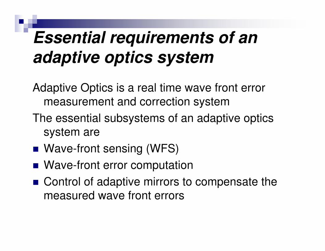
Adaptive Optics is a real time wave front error
measurement and correction system
The essential subsystems of an adaptive optics
system are
� Wave-front sensing (WFS)
� Wave-front error computation
� Control of adaptive mirrors to compensate the
measured wave front errors

Wave front sensing
The essential subsystems of a wave front sensor are:
Lenslet array or Shearing Interferometer to sample wave front (WF) at very short intervals dictated by ‘seeing’
Very fast image acquisition system to capture the WF
Computer system to do image processing and to calculate errors in the wave frontWavefront errors can be classified into two broad categories
Tilt in the wave frontHigh frequency corrugation in the wavefront

x-tilt Y tilt Defocus
X and Y tilt
combined
Coma along x axis 5th order Astigmatism
Typical aberration in the wavefront

Lab Implementation and testing of SHWS
• Aberration free reference
beam
• Tip-tilt mirror system to
introduce known WF error
• SH lenslet array (10x10) to sample the wavefront
• Fast CCD / CIS (CMOS) and PC to capture the image and for computation

Shack-Hartmann lenslet images with tilted wave fronts produced by a piezo-electric actuator based tip-tilt mirror
6 x 6 lenslet images (Lenslet size 300 µm)Images captured by cooled EMCCD
abc are three actuators of tip-tilt mirrora0b0c0 is a reference image (plane wave front without errors)when 0 v is applied to all actuatorsa0b1c1 is a tilted wavefront by applying 1 volt to b and c actuator
Shack Hartmann WF sensor implementation and results

ZernikeCoefficient a0b5c5 a0b10c10 a0b15c15 a0b20c20
1 Tilt aboutX axis
-0.01948 -0.061855 -0.08133 -0.08879
2 Tilt aboutY axis
-0.09832 -0.16985 -0.24516 -0.35071
3 Astigmat.+/-45deg
-0.00905 -0.02567 0.0085664 0.026946
4 Defocus -0.01587 -0.035064 -0.024667 -0.04001
5 Astigmat.0,90 deg
0.011256 -0.016897 -0.028187 0.015153
6 Trefoil x axis
-0.00383 -0.01878 -0.026595 -0.00912
7 3rdorderComa x
0.002477 -0.002104 0.00436 0.007624
8 3rdorderComa y
-0.0069 -0.013929 -0.012244 -0.01787

Measured tilt Vs Voltage
Slide 4
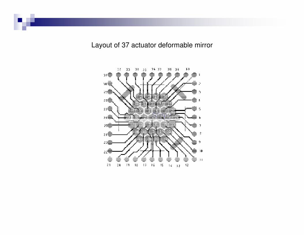
Layout of 37 actuator deformable mirror

MEMS Based Adaptive Mirror characterization with Long Trace Profilometer
Deformable Mirror Response
-0.08
-0.06
-0.04
-0.02
0
0.02
0.04
0.06
0 5 10 15 20 25 30
Mirror Diagonal (mm)
Mirro
r Deflection (x100
)
Actuators 2-7, 100V
Rest 50V

Optical layout of wave front measurement and correction system

Adaptive mirror
Tip-tilt mirror
Beam reduction unit
Lenslet with CCD
Photograph of experimental setup in the lab
Fibre optic light source
with pin-hole
Telescope in
autocollimation mode

Lab Experiments with AO Mirror
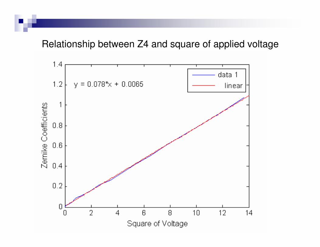
Relationship between Z4 and square of applied voltage


VBT Optical Parameters
The important parameters of 2.3 m VBT are given below
� Diameter :2360 mm
� Clear aperture : 2320 mm� Material : Zerodur� Density : 2.52 gm / cc� Cassegrain hole dia : 720 mm� Central obscuration :0.3
� Prime focus F ratio :3.237� Prime image scale :27.463 “ / mm� Cassegarin focus F ratio : 12.97� Aperture of Secondary mirror : 630 mm� Cassegrain image scale : 6.854 “ / mm

Solid Model of VBT


Spot Diagram
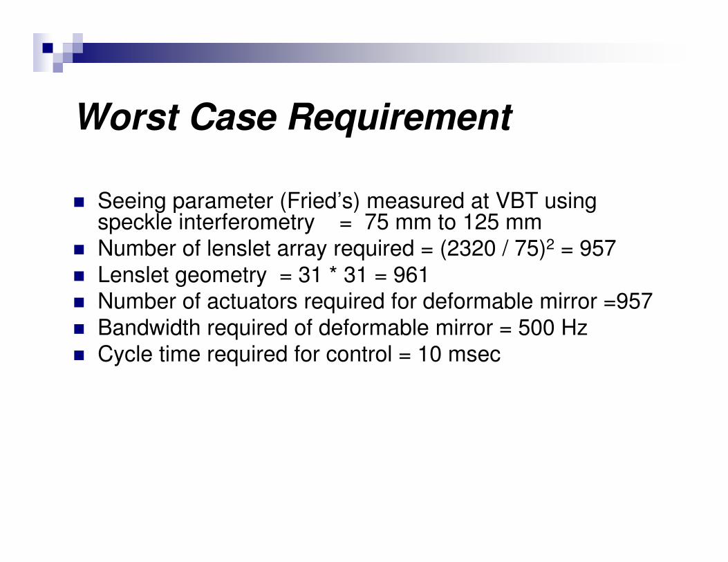
Worst Case Requirement
� Seeing parameter (Fried’s) measured at VBT using speckle interferometry = 75 mm to 125 mm
� Number of lenslet array required = (2320 / 75)2 = 957� Lenslet geometry = 31 * 31 = 961� Number of actuators required for deformable mirror =957� Bandwidth required of deformable mirror = 500 Hz� Cycle time required for control = 10 msec

Typical AO system design� No of actuators available in a low cost deformable mirror = 59� No of lenslet array required = 100 (10 x 10) (60 % for mirror
control)� No. of pixels for subaperture = 10 x 10� CMOS imager region of interest = 100 x 100 pixels� No. of frames obtained for 128 by 128 pixel region = 50 frames /
sec� Minimum time required for one loop 20 msec. If this rate is too high,
reduce the no.of lenslet points or go for high frame rate camera� If 24 µm pixel is chose, CMOS pixel area covered = 3.2 mm x 3.2
mm� In-coming collomated beam diameter = 20 mm� Choose an adaptive mirror based on affordability and avilability� Use a beam reduction unit 20 mm to 3.5 mm dia.

Typical Parameters of AO Mirror
� Membrane mirror : 5 0. µm silicon membrane coated with nitride and 0.2 µm Aluminum
� Dia. of mirror : 15 mm� Usable dia. : 10 mm� Actuator : Hexagon shaped PCB pad
� Spacing of actuator : 1.75 mm center to center� Distribution : Actuators are in 3 concentric rings around a central � Actuator with 6, 12 and 18 actuators in the rings� Max. deflection : 5 µm
� Piezo electric actuator based mirrors are available with large diameter with $2000 per actuator. For 37 actuators, cost is about $80000
� Small size piezo mirrors are cheaper

MMDM of Boston Univ. Mirror
� Membrane size : 2 mm x 2 mm x 2 µm� Active mirror area : 1 cm2 � Number of actuators : 100 � Actuator size : 300 µm x 300 µm� Actuation : Integrated electrostatic � Package size : 10 cm3 � Power consumption : 0.2 W / channel � Actuator spacing : 0.3 mm � Actuator stroke : 2 µm � Actuator repeatability : 10 nm � Hysteresis : 0% � Surface roughness : 50 nm (root mean square) � Bandwidth in air : 7 kHz � Maximum deflection : 1.9 µm at 241 V

Current activities for AO implementation in VBT
• Shack Hartmann lenslet array images are captured using Andor EMCCD on 20 Feb. 2007
• The following points may be noted• Image is rectangular, this is because of rectangular pixel of the CCD• Spider positions distorts the lenslet images• Better CCD camera, adaptive mirror and tip tilt mirror are being searched • For fast processing of data and control, high speed multi core processors and related
hardware is being probed

Current activities…. A mechanical breadboard is fabricated to mount reference beam and other
components at the cass focus of VBT
• The breadboard is being assembled and tested with the Cass focus simulator abricated earlier
• Next experiments will be conducted at VBT during May 07
