proposed hotel best western
TRANSCRIPT

Proposed Hotel – Best Western
160 Hearst Way, City of Ottawa
Site Servicing and Stormwater Management Report
Prepared for:
Arif Shariff Diamond Jubilee Hospitality Inc. 4020 Otter Tail Cr. Ottawa, Ont. K1V 1R1
Prepared by:
McIntosh Perry
115 Walgreen Road
Carp, ON
K0A 1L0
REV01: July 4th, 2016
REV03: October 18th, 2016
CP-16-0372
City File No. D07-12-15-0078

160 Hearst Way Proposed Hotel
CP-16-0372 Site Servicing & Stormwater Management Report
i
TABLE OF CONTENTS
1.0 PROJECT DESCRIPTION ........................................................................................................................................1
1.1 Site Description ....................................................................................................................................................... 1
2.0 BACKGROUND STUDIES .......................................................................................................................................2
3.0 PRE-CONSULTATION SUMMARY ..........................................................................................................................2
4.0 EXISTING SERVICES .............................................................................................................................................3
4.1 Hearst Way ............................................................................................................................................................. 3
4.2 Service Easement .................................................................................................................................................... 3
5.0 SERVICING PLAN .................................................................................................................................................3
5.1 Water Servicing ...................................................................................................................................................... 3
5.2 Sanitary Servicing ................................................................................................................................................... 4
5.3 Storm Servicing ....................................................................................................................................................... 4
6.0 STORMWATER MANAGEMENT ............................................................................................................................5
6.1 Design Methodology .............................................................................................................................................. 5
6.2 Site Drainage .......................................................................................................................................................... 5
6.2.1 Pre-Development Drainage ............................................................................................................................. 5
6.2.2 Post-Development Drainage ........................................................................................................................... 6
6.3 Quantity Control ..................................................................................................................................................... 6
6.4 Quality Control ....................................................................................................................................................... 8
7.0 SEDIMENT AND EROSION CONTROL ....................................................................................................................9
8.0 SUMMARY ..........................................................................................................................................................9
9.0 RECOMMENDATION ......................................................................................................................................... 10
LIST OF FIGURES
FIGURE 1: KEY MAP: 160 HEARST WAY, CITY OF OTTAWA ...........................................................................................1

160 Hearst Way Proposed Hotel
ii
CP-16-0372 Site Servicing & Stormwater Management Report
LIST OF TABLES
TABLE 1: PRE-DEVELOPMENT DRAINAGE SUMMARY ...................................................................................................6
TABLE 2: POST-DEVELOPMENT RUNOFF CALCULATIONS ..............................................................................................6
TABLE 3: ALLOWABLE RELEASE RATE ..........................................................................................................................7
TABLE 4: POST-DEVELOPMENT RESTRICTED RUNOFF CALCULATIONS ..........................................................................7
TABLE 5: STORAGE SUMMARY ....................................................................................................................................8
LIST OF APPENDICES APPENDIX A: PRE-CONSULTATION NOTES
APPENDIX B: WATER AND FIRE PROTECTION CALCULATIONS
APPENDIX C: SANITARY CALCULATIONS
APPENDIX D: PRE-DEVELOPMENT PLAN
APPENDIX E: POST-DEVELOPMENT PLAN
APPENDIX F: STORMWATER CALCULATIONS
APPENDIX G: QUALITY TREATMENT UNIT DESIGN DETAILS
APPENDIX H: CITY OF OTTAWA CHECK LIST

160 Hearst Way Proposed Hotel
1
CP-16-0372 Site Servicing & Stormwater Management Report
1.0 PROJECT DESCRIPTION
This report will address the servicing (water, sanitary & storm) and stormwater management treatment
associated with the proposed development of the hotel building located at 160 Hearst Way within the City of
Ottawa. This report should be read in conjunction with drawings C101 – Lot Grading, Drainage & Sediment
Control Plan and C102 – Servicing & Utility Plan (Reference No. CP-16-0372).
1.1 Site Description
The property is located at 160 Hearst Way in the City of Ottawa and covers approximately 0.61 ha. It is
described as Block 4 and Part of Blocks 3 and 5, Registered Plan M-310, City of Ottawa.
The existing site is currently undeveloped and consists largely of grass cover and vegetation. The current
zoning for the site is IL1 – Light Industrial; however the proposed use for the site will be a commercial hotel.
The site is bound by Highway 417 to the north, the Eagleson Road off-ramp from Highway 417 to the
northeast and Hearst Way to the south. The adjacent lands to the east (140 Hearst Way) and west (170
Hearst Way) are currently developed. See Figure 1: Key Map.
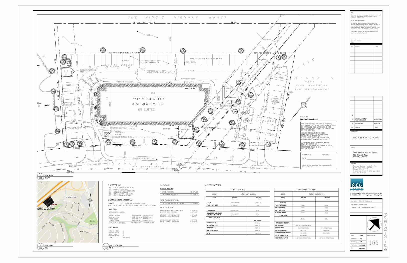
The proposed development consists of a standalone 925 m2 hotel building complete with an associated
parking lot and landscaped areas. The building will be centrally located within the property and be 4-storeys
in height with 69 suites, a lobby/breakfast area and fitness room. There will not be an indoor pool as a
building amenity. Parking will be located along the north, east and west property lines. No parking will be
located between the building and the southwest property line.
Figure 1: Key Map: 160 Hearst Way, City of Ottawa

160 Hearst Way Proposed Hotel
2
CP-16-0372 Site Servicing & Stormwater Management Report
2.0 BACKGROUND STUDIES
Background studies have been completed for the site. These studies include a review of the City of Ottawa as-
builts, a topographical survey of the site, a geotechnical report, Phase ONE and TWO Environmental Site
Assesments and the previous design submission completed by Basetech Consulting Inc.
As-built drawings of the existing services within the vicinity of the site were reviewed in order to determine
proper servicing and stormwater management schemes for the site.
A topographic survey of the site was completed by Annis, O`Sullivan, Vollebekk Ltd. (AOV) dated June 14th,
2012, and can be found under separate cover.
The following reports have previously been completed and are available under separate cover:
Phase I Environmental Site Assessment completed by Houle Chevrier Engineering dated October
10, 2014.
Phase II Environmental Site Assessment completed by Houle Chevrier Engineering dated December
22, 2014.
Geotechnical Investigation completed by Houle Chevrier Engineering dated February 11, 2016.
3.0 PRE-CONSULTATION SUMMARY
City of Ottawa and Mississippi Valley Conservation Authority (MVCA) staff have been pre-consulted via email
on June 28th, 2016 regarding this proposed development. Specific design parameters to be incorporated
within this design include the following:
The 100 year post development storm flows must be restricted to the 5 year pre-development flow
calculated with a ‘C’ value of 0.7 (as per the approved drainage and grading plan for the area,
attached in Appendix ‘A’)
o The allowable release rate shall be calculated based on an intensity obtained from the old
City of Kanata IDF rainfall curve. Post development flows shall be based on the Ottawa IDF
curve.
Pre development flows are to be calculated with a time of concentration (Tc) of 20 min whereas post
development flows are to be calculated with a Tc of 10 min
If underground/inline stormwater storage is proposed, the engineering consultant is required to
assume an average release rate equal to 50% of the determined peak allowable rate. Otherwise,
disregard the underground/inline storage as available storage or provide modeling to support the
proposed design.
Mississippi Valley Conservation Authority requires 70% total suspended solids (TSS) removal for
quality treatment at this site.
Correspondence with the City and Conservation Authority can be found in Appendix ‘A’.

160 Hearst Way Proposed Hotel
3
CP-16-0372 Site Servicing & Stormwater Management Report
4.0 EXISTING SERVICES
4.1 Hearst Way
Within Hearst Way there is an existing 450 mm diameter sanitary sewer that flows east and a 250 mm
diameter sanitary sewer that flows west. Both sewers connect and flow north through a sanitary easement.
There is a 300 mm diameter water main that services the sites along Hearst Way along with existing fire
hydrants. There are two storm systems within Hearst Way; a 1,200 mm diameter sewer that flows east
before draining through a storm easement and a 300 mm diameter sewer that starts centrally in front of the
site and flows east towards Eagleson Road.
There is a service easement located southwest of the site that currently includes a 1,200 mm diameter storm
main, and 600 mm diameter sanitary main.
Hydro, gas, cable and bell services are available from Hearst Way.
New storm, sanitary and water laterals will be extended from the existing mains within Hearst Way to service
this site as detailed in Section 5.0 below.
4.2 Service Easement
A trunk sanitary sewer easement granted in favour of the City as per Transfer of Easement Agreement
LT282905 [designated as Part 2 on Reference Plan registered as Plan 4R-23553] and a trunk storm sewer
easement granted in favour of the City as per Transfer of Easement Agreement LT238232 [designated as
Parts 4 and 5 on Reference Plan registered as Plan 4R-23553] are present on the subject site.
Within the service easements located along the east portion (Reference Plan 4R-23553) of the site there is a
1,200 mm diameter storm main, and 600 mm diameter sanitary main.
5.0 SERVICING PLAN
5.1 Water Servicing
A new 150 mm diameter PVC water lateral, complete with valve at the property line will be constructed from
the existing 300 mm water main located within Hearst Way to service the proposed building.
The proposed building will be equipped with a sprinkler system for fire protection. The required fire
protection from the Fire Underwritters Survey (FUS) is 5,000 L/min (provided for information purposes only).
Available flow from the hydrant located along Hearst Way is approximately 9,638 L/min with a residual
pressure of 20 PSI (See Appendix ‘B’ for information sheets). The existing hydrant is within 45m of the
Siamese connection, therefore a private hydrant is not required for this site.

160 Hearst Way Proposed Hotel
4
CP-16-0372 Site Servicing & Stormwater Management Report
Additionally, a WaterCAD model was completed to ensure the proposed lateral can properly service the site.
The site will require a pressure reducing valve (PRV) as the pressure within the lateral would be greater than
80 PSI. The results of the water model can be found in Appendix ‘B’ and a digital copy has been submitted to
the City.
The water demands for the new building have been calculated as per the Ottawa Design Guidelines – Water
Distribution and are as follows: the average and maximum daily demands are 0.36 L/s and 0.54 L/s
respectively. The maximum hourly demand was calculated as 0.97 L/s (Refer to Appendix ‘B’ for flow details).
5.2 Sanitary Servicing
A new 200 mm diameter gravity sanitary service will be connected to the existing 450 mm diameter sanitary
main within Hearst Way. The building will be serviced via gravity drainage to the sanitary main. The service
connection will be laid in a common trench with the proposed water and storm services. A sanitary service
manhole located near the property line will also be proposed.
The proposed peak design flows for the new building were calculated using the Second Edition of the City of
Ottawa Sewer Design Guidelines (OSDG) dated October 2012 and the calculations can be found in Appendix
‘C’. The peak design flow for the sanitary system was calculated to be 3.90 L/s. The proposed 150 mm
diameter sanitary sewer service will adequately carry these flows.
Furthermore, from information provided by the owner, the maximum number of people within the building
will be 230, (218 Hotel Guests, 12 Staff members and seating for 44 in the breakfast area). The calculated
flow for this occupancy was determined to be 2.55 L/s (See Appendix ‘C’ for detailed calculations). It is
anticipated that there will be no issues with capacity constraints within the existing sanitary main as the
amount of flow leaving the site is negligible.
Based on the sanitary sewer design completed by J.L. Richards the upstream sanitary network has a noted
population of 4,545, as noted on the sanitary drainage plan. This generates a flow rate of 60.62 L/s (350
L/person including peaking factor and infiltration) The existing 450 mm diameter sanitary main has a capacity
188.1 L/s with a 0.4% slope, there is sufficient capacity within the sanitary main within Hearst Way, even if
the upstream flows were tripled.
The downstream sanitary network flows to the service easement and then north under Highway 417.
5.3 Storm Servicing
A new storm sewer system will be extended from the 1,200 mm diameter storm main fronting the site within
Hearst Way. The new on-site pipe network will collect storm flows and restrict the runoff prior to leaving the
site. The Storm system will be further detailed in Section 6.0.
The downstream storm sewer connects to the existing 2,700 mm diameter trunk sewer within the Highway
417 right-of-way and outlets to Watts Creek.

160 Hearst Way Proposed Hotel
5
CP-16-0372 Site Servicing & Stormwater Management Report
6.0 STORMWATER MANAGEMENT
Stormwater management for this site is maintained through positive drainage away from the proposed
building and into a new underground storm sewer system within the site. The storm runoff will drain into the
underground pipe network through catch basins (CB) and catch basin manholes (CBMH) located throughout
the site. The runoff will gravity drain through the underground storm pipes where it eventually outlets to the
storm main located within Hearst Way. The quantitative and qualitative properties of the storm runoff for
both the pre and post development flows are further detailed below.
6.1 Design Methodology
Runoff calculations in this report are derived using the Rational Method, given as:
Q=2.78 CIA (L/s)
C=Runoff coefficient I=Rainfall intensity in mm/hr. A=Drainage area in hectares
It is recognized that the rational method tends to overestimate runoff rates. As a by-product of using a
conservative prediction method, any facilities that are sized using these results are expected to function as
intended in real world conditions.
In conjunction with the OSDG the following runoff coefficients were used to develop a balanced ‘C’ for each
drainage area:
Building roofs, Asphalt, Concrete 0.90 Grass, undeveloped areas 0.20 Gravel 0.60
As per the City of Ottawa Sewer Design Guidelines, the 5-year balanced ‘C’ value must be increased by 25%
for a 100-year storm event to a maximum of 1.0.
As per the pre-consultation meeting with the City the time of concentration (Tc) used for pre-development
and post-development flows shall be calculated using a time of concentration (Tc) of 20 minutes and 10
minutes respectively. Additionally, the pre-development flows will be calculated based on an intensity
obtained from the former City of Kanata IDF rainfall curve. The post-development flows have been based on
the Ottawa IDF curve as per the OSDG.
6.2 Site Drainage
6.2.1 Pre-Development Drainage
The existing site has been demonstrated as drainage area A1. Drawing CP-16-0372 PRE (Appendix ‘D’)
indicates the limits of these drainage areas. The existing site is mainly grass and vegetation. The site drains via
overland flow towards Highway 417 in its current state.

160 Hearst Way Proposed Hotel
6
CP-16-0372 Site Servicing & Stormwater Management Report
Table 1: Pre-Development Drainage Summary
Basin Drainage Area (ha)
Balanced Runoff Coefficient (C) 5-
yr
Balanced Runoff Coefficient (C) 100-yr
5-Year Flow Rate (l/s)
100-Year Flow Rate
(l/s)
A1 0.61 0.20 0.25 23.6 43.9
Total 0.61 #REF! #REF! 23.6 43.9
(See Appendix ‘F’ for Calculations)
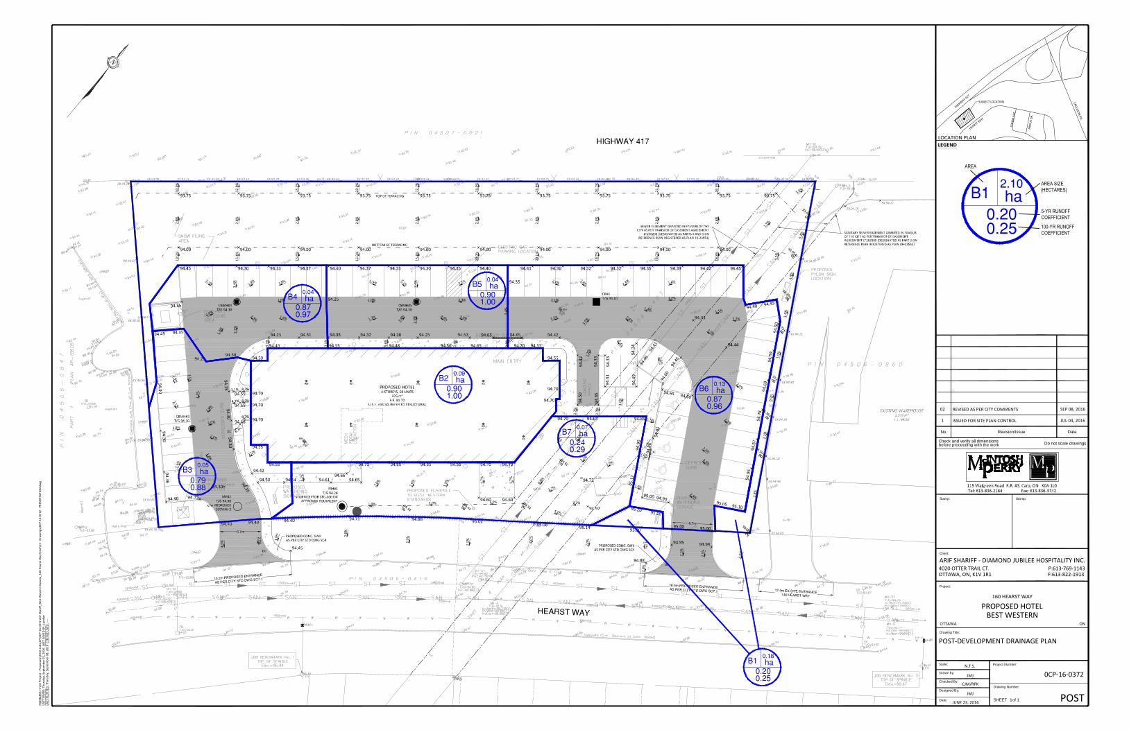
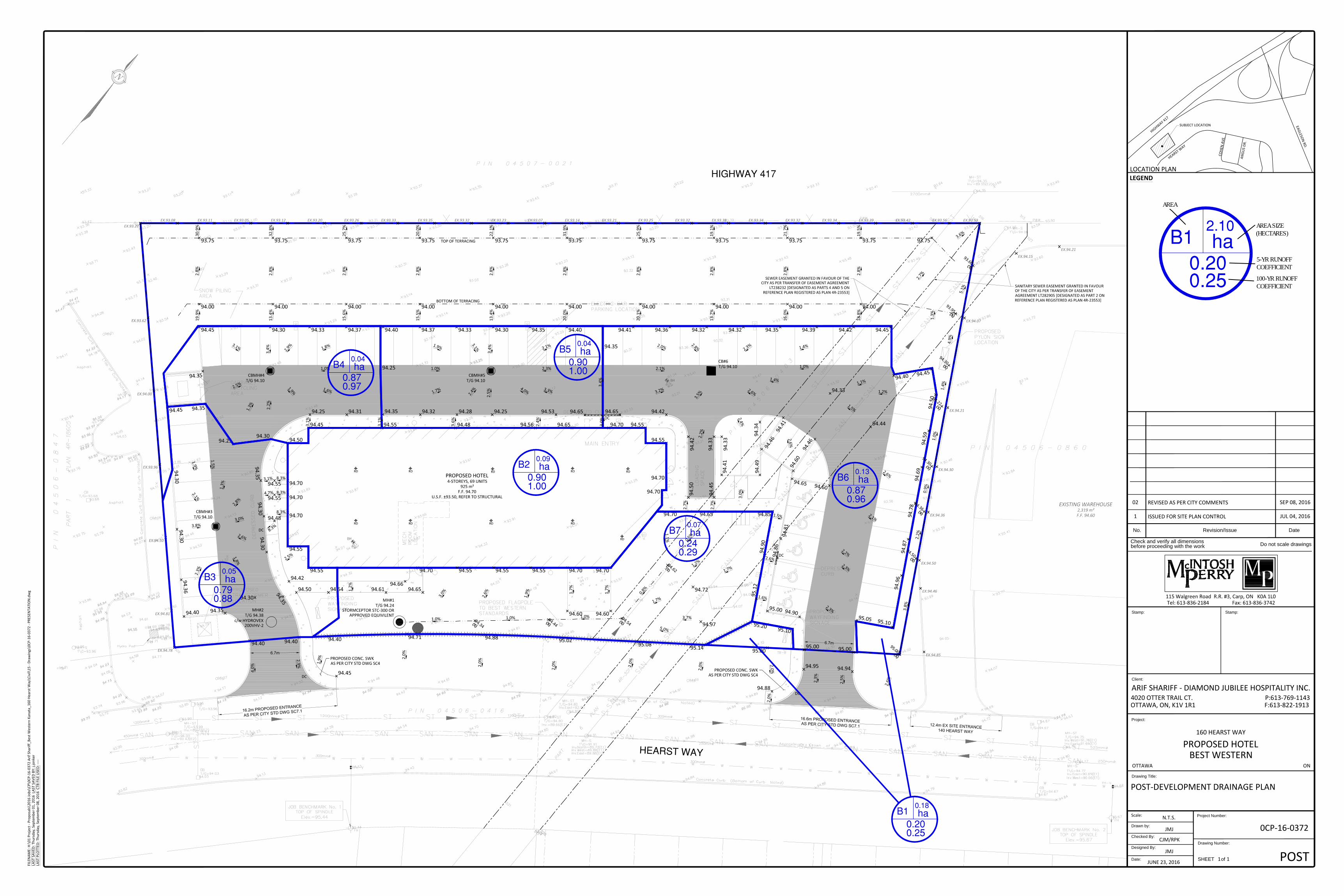
6.2.2 Post-Development Drainage
The proposed site has been demonstrated as drainage areas B1-B7 Drawing CP-16-0372 Post (Appendix ‘E’)
indicates the limits of these drainage areas.
Table 2: Post-Development Runoff Calculations
Basin Drainage Area
(ha)
Balanced Runoff
Coefficient (C) 5-yr
Balanced Runoff
Coefficient (C) 100-yr
5-Year Flow Rate (l/s)
100-Year Flow Rate (l/s)
B1 0.18 0.20 0.25 10.3 22.2
B2 0.09 0.90 1.00 24.1 45.9
B3 0.05 0.79 0.88 12.5 23.8
B4 0.04 0.87 0.97 9.9 18.9
B5 0.04 0.90 1.00 10.9 20.8
B6 0.13 0.87 0.96 33.4 63.1
B7 0.07 0.24 0.29 4.7 9.8
Total 0.61 0.32332478 0.367836297 105.8 204.4
(See Appendix ‘F’ for Calculations)
Due to stormwater management requirements, the amount of flow that is permitted to leave the site must
not exceed the allowable 82.5 L/s. Since the site will have substantially higher post-development flows a flow
restriction will be required, creating a need for onsite storage. This restriction will be further detailed in
Section 6.3 below.
6.3 Quantity Control
After discussing with city staff the stormwater management criteria for the site, the total post development
runoff for this site has been restricted to the 5-year pre-development flow rate generated from the entire site
area using an overall ‘C’ value of 0.70, a Tc of 20 minutes and the intensity obtained from the old City of
Kanata IDF rainfall curve (See Appendix ‘A’ for pre-consultation notes). These values create an allowable
release rate of 82.5 L/s as mentioned above.

160 Hearst Way Proposed Hotel
7
CP-16-0372 Site Servicing & Stormwater Management Report
Table 3: Allowable Release Rate
Basin Drainage Area (ha) Balanced Runoff Coefficient (C) 5-yr 5-Year Flow Rate (l/s)
A1 0.61 0.70 82.5 (See Appendix ‘F’ for Calculations)
Reducing site flows will be achieved using a flow restriction, and will create the need for onsite storage.
Runoff from areas B2 through B6 will be restricted as detailed in the table below.
Table 4: Post-Development Restricted Runoff Calculations
Area Post-Development Unrestricted (l/s) Post-Development (Restricted) (l/s)
5-yr 100-yr 5-yr 100-yr
B1 10.3 22.2 10.3 22.2 UNRESTRICTED
B2 24.1 45.9 3.0 4.8
RESTRICTED
B3 12.5 23.8
45.8 45.8 B4 9.9 18.9
B5 10.9 20.8
B6 33.4 63.1
B7 4.7 9.8 4.7 9.8 UNRESTRICTED
Total 105.8 204.4 63.8 82.5 (See Appendix ‘F’ for Calculations)
Runoff from Area B2 will be restricted through roof drains before discharging to the proposed storm network
along the front of the site and eventually to the existing main within Hearst Way. The total flow leaving the
roof will be 3.00 L/s and 4.80 L/s during the 5 and 100-year storm events, respectively. This will result in
ponding depths of 25 mm and 40 mm for the 5-year and 100-year storm events, respectively. All of the
storage required for this area will be located on the proposed roof, and emergency roof scuppers will be
installed to ensure ponding does not exceed the proposed ponding limits.
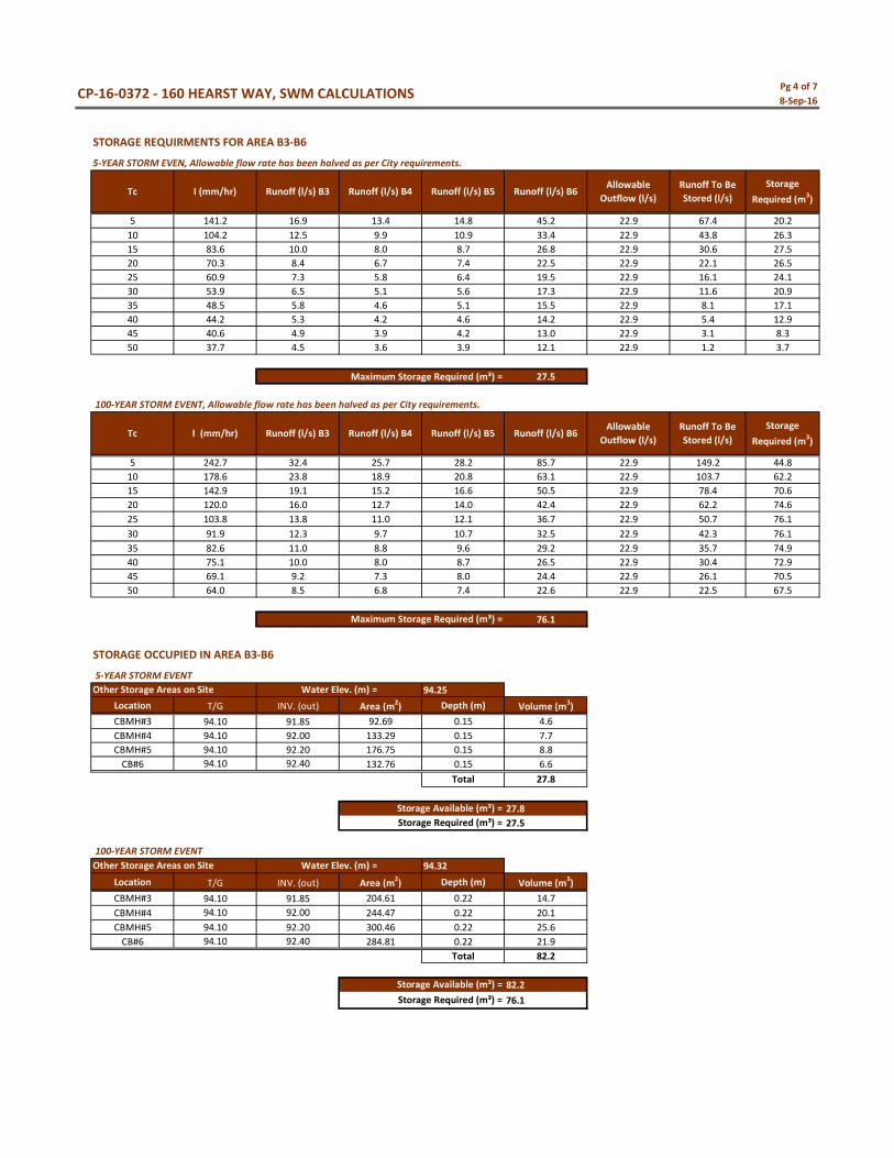
Runoff from Areas B3-B6 will be restricted within the parking lot area within the north and western portions
of the site through the use of a Hydrovex 200VHV-2 ICD (Design Head 2.62 m) within MH#2. The ICD will
restrict areas B2-B6 to 45.8 L/s for the 5 and 100-year storm events. However, as per the pre-consultation
discussion, this release rate will be halved to 22.9 L/s when determining the required storage volumes. This
restriction will also create a water surface elevation (WSEL) of 94.25 m for the 5-year storm event and 94.32
m for the 100-year storm event. The storage for this area will be provided within the dry grass swale along
the east property line.

160 Hearst Way Proposed Hotel
8
CP-16-0372 Site Servicing & Stormwater Management Report
In the event that there is a rainfall above the 100-year storm event, or a blockage within the storm network,
an emergency overland flow route has been provided such that the storm water runoff will be conveyed
towards the south property line away from the building, and into the existing storm network within Hearst
Way. A minimum elevation difference of 0.30 m has been provided from the finished floor of the building
(94.70 m) to the overland flow route elevation (94.40 m).
The following table summarizes the storage requirements and the depth of the water ponding during the 5
and 100-year storm events to meet the required storage volumes.
Table 5: Storage Summary
Area Depth of
ponding (m) for 5-year storm
5-year required
storage (m3)
5-year available
storage (m3)
Depth of ponding (m) for 100-year storm
100-year required
storage (m3)
100-year available
storage (m3)
B2 0.025 17.3 23.1 0.40 35.0 37.0
B3-B6 0.15 27.5 27.8 0.22 76.1 82.2 (See Appendix ‘F’ for Calculations)
6.4 Quality Control
The Mississippi Valley Conservation Authority (MVCA) was contacted on June 28th, 2016 in order to identify
the quality control requirements for this site. A normal level of protection which involves a quality control of
70% Total Suspended Solids (TSS) removal is required for the site. Details can be found in Appendix ‘A’.
The development of this lot will employ Best Management Practices (BMP’s) wherever possible. The intent
of implementing stormwater BMP’s is to ensure that water quality and quantity concerns are addressed at all
stages of development. BMP’s at this site will be implemented at the lot level.
Lot level BMP’s typically include temporary retention of the parking lot runoff, minimizing ground slopes and
maximizing landscaped areas. There is a limited opportunity to employ these techniques at this site.
One orifice plug will restrict flows from the site, causing temporary ponding. There will be an opportunity for
particle settlement during this process, but the full benefits of a larger scale end-of-pipe facility will not be
fully realized at this site.
A quality treatment unit has been sized to provide a TSS removal rate of 70% as per MVCA requirements. The
Stormceptor STC-300 Unit will provide a water quality of 76% TSS (See Appendix ‘G’ for Calculation sheets).
This treatment unit has a sediment capacity of 1,450 L, total holding capacity of 1,775 L, an oil storage
capacity of 300 L and a treatment flow rate of 9 L/s. The Stormceptor STC-300 Unit shall be placed
downstream of the ICD and will provide the required water quality treatment for the site runoff before
entering the storm main within Hearst Way. Information regarding the long-term removal rate of the
Stormceptor STC-300 unit has been included within Appendix ‘G’ for reference.

160 Hearst Way Proposed Hotel
9
CP-16-0372 Site Servicing & Stormwater Management Report
7.0 SEDIMENT AND EROSION CONTROL
The contractor shall implement best management practices, to provide for protection of the area drainage
system and the receiving watercourse, during construction activities. The site-grading contractor is
responsible for ensuring sediment control structures are installed in accordance with the Site Servicing and
Site Grading and Drainage Plan as indicated. Silt fences shall be installed on site before construction or earth-
moving operations begin, as shown on the grading plan.
Geosock inserts with an overflow is to be installed under the grates of all catch basins immediately upon its
installation. The geosock is to be removed only after all areas have been paved. Care shall be taken at the
removal stage to ensure that any silt that has accumulated is properly handled and disposed of. Removal of
silt fences or straw bale check dams without prior removal of the sediments shall not be permitted.
At the discretion of the project manager, municipal staff or conservation authority, additional silt control
devices shall be installed at designated locations.
8.0 SUMMARY
A new 925 m2 hotel building in the City of Ottawa is proposed at 160 Hearst Way.
New 150 mm sanitary and 150 mm water laterals will be extended from the existing mains within
Hearst Way to service the new building.
A new storm system will be installed onsite and will convey stormwater into the existing storm
sewer network located within Hearst Way.
As discussed with the City of Ottawa staff, the stormwater management design will ensure that the
post-development 100 year flow rate does not exceed the 5 year pre development flow rate using
an overall ‘C’ value of 0.70.
Storage of storm runoff will be provided within parking areas above the storm structures on site.
Stormwater quality treatment will be designed to remove 70% TSS per MVCA requirements.

160 Hearst Way Proposed Hotel
10
CP-16-0372 Site Servicing & Stormwater Management Report
9.0 RECOMMENDATION
We respectfully recommend that:
This revised report, dated October 18th, 2016, and the associated site grading, drainage and servicing plans be
approved for engineering details.
The sediment and erosion control plan outlined in Section 7.0 and detailed in the Lot Grading, Drainage,
Sediment and Erosion Control Plan notes are to be implemented by the contractor.
This report is respectfully being submitted for approval.
___________________________
Ryan Kennedy, P.Eng. Jonathan Jonker, C.E.T., rcsi
Practice Area Lead - Land Development Land Development Designer
(613) 836-2184 Ext.2243 (613) 836-2184 Ext.2252 [email protected] [email protected]

APPENDIX A: PRE-CONSULTATION NOTES

1
Jonathan Jonker
From: Fraser, Mark <[email protected]>Sent: June-28-16 3:37 PMTo: Jonathan JonkerSubject: RE: 160 Hearst Way - SWM ConfirmationAttachments: City of Kanata Rainfall Curves IDF, KSD-0.01.pdf; plan3.pdf
Follow Up Flag: Follow upFlag Status: Flagged
Hi Jonathan,
Please accept this email as confirmation that the SWM criteria stated in the email below is correct.
Stormwater quantity control for the subject site is required to control post-development flows, up to andincluding the 100-year storm event, to a 5-year allowable release rate calculated using a runoff coefficient of 0.7and a time of concentration (Tc) of 20 minutes.The allowable release rate shall be calculated based on an intensity obtained from the old City of Kanata IDF rainfallcurve. Please find attached a copy of the IDF curve to reference and provide in the Appendix of the report. Postdevelopment flows shall be based on the Ottawa IDF curve.Please note if underground/inline stormwater storage is proposed, the engineering consultant is required toassume an average release rate equal to 50% of the determined peak allowable rate. Otherwise, disregard theunderground/inline storage as available storage or provide modeling to support the proposed design. Thehalving is based on a concept put forward by the Water Resources Unit at the City of Ottawa that the dischargerate at full storage is not representative of the discharge rate for more frequent storm events. The halveddischarge rate is a methodology that compensates for the inaccuracy of the modified rational method whenunderground/inline storage is applied.Please consult with the Mississippi Valley Conservation Authority (MVCA) regarding water quality control for thesubject site as the minor system outlets to Watts Creek. The site is subject to the requirements identified withinthe Shirley’s Brook and Watts Creek Subwatershed Study, September 1999.Please note that correspondence with the Ministry of Environment and Climate Change (MOECC) is required tobe provided in the Appendix of the report as the subject site is zoned IL – Light Industrial Zone.A similar report in terms of context to the Site Servicing Report provided for 140 Hearst Way is anticipated.
If you have any questions please let me know.
Regards,
Mark FraserJunior Infrastructure Engineer, Suburban Services
City of Ottawa | Ville d'OttawaPlanning and Growth Management Department110 Laurier Avenue West. 4th Floor, Ottawa ON, K1P 1J1Tel:613.580.2424 ext. 27791Fax: 613-580-2576Mail: Code 01-14

2
Email: [email protected]
*Please consider your environmental responsibility before printing this e-mail
This message, including any document or file attached, is intended only for the addressee and may contain privileged and /or confidential information. Any person is strictlyprohibited from reading, using, disclosing or copying this message. If you received this message in error, please notify the sender and delete the message. Thank you.
From: Jonathan Jonker [mailto:[email protected]]Sent: June 28, 2016 10:30 AMTo: Fraser, MarkSubject: 160 Hearst Way - SWM Confirmation
Good Morning Mark,
I just wanted to confirm that this site will have the same SWM criteria as the adjacent site we designed (140 Hearst Way– Franklin Empire).
The 100 year post development storm flows must be restricted to the 5 year pre-development flow calculatedwith a ‘C’ value of 0.7 (as per the attached drawing)Pre development flows are to be calculated with a Tc of 20 min whereas post development flows are to becalculated with a Tc of 10 minContact MVCA for quality control measures (70% TSS is anticipated)
If you need any additional information please do not hesitate to call or email.
Thank you very much,
Jonathan Jonker, C.E.T.Designer / Inspector | Land Development115 Walgreen Road, RR 3, Carp, ON K0A 1L0T. 613.836.2184 (2252) | F. 613.836.3742 | C. [email protected] | www.mcintoshperry.com
This e-mail originates from the City of Ottawa e-mail system. Any distribution, use or copying of this e-mail orthe information it contains by other than the intended recipient(s) is unauthorized. Thank you.
Le présent courriel a été expédié par le système de courriels de la Ville d'Ottawa. Toute distribution, utilisationou reproduction du courriel ou des renseignements qui s'y trouvent par une personne autre que son destinataireprévu est interdite. Je vous remercie de votre collaboration.


1
Jonathan Jonker
From: Myra Van Die <[email protected]>Sent: June-29-16 4:13 PMTo: Jonathan JonkerSubject: RE: 160 Hearst Way - SWM Quality Control
Follow Up Flag: Follow upFlag Status: Completed
Hi Jonathan,
That is correct, we recommend a normal level of quality treatment be provided.
Regards,
Myra Van Die, P.Eng. | Water Resources EngineerMississippi Valley Conservation Authority
From: Jonathan Jonker [mailto:[email protected]]Sent: Tuesday, June 28, 2016 10:36 AMTo: Myra Van DieSubject: 160 Hearst Way - SWM Quality Control
Good Morning Myra,
We have been brought on to this project to obtain City approval and are completing our own due diligence.
Can you confirm the quality control measures for the site are similar to the adjacent site we designed (140 Hearst Way –Franklin Empire), this site is assumed fish habitat and a long-term average removal of 70% of suspended solids isrequired.
If you require anything else, please feel free to call or email.
Thank you very much,
Jonathan Jonker, C.E.T.Designer / Inspector | Land Development115 Walgreen Road, RR 3, Carp, ON K0A 1L0T. 613.836.2184 (2252) | F. 613.836.3742 | C. [email protected] | www.mcintoshperry.com

1
Jonathan Jonker
From: Jonathan JonkerSent: June-28-16 4:39 PMTo: Emily Diamond ([email protected])Subject: 160 Hearst WayAttachments: 152 r00 - Site Plan scheme R - GLO Kanata - ACI Wright Architects.pdf
Good Afternoon Emily,
We are completing a the civil design for a new hotel in the City of Ottawa located at 160 Hearst Way. The City is askingfor us to correspond with the MOECC to confirm the requirements for an ECA.
The site is IL – Light Industrial, however the site is being developed as a commercial hotel (Best Western). Ourinterpretation of Section 3 of Ontario Regulation 525/98 is that this site is exempt as it meets the below subsections.
As in the past, ECA requirements for storm water should be based on the use of the property and not what the propertyhas been zoned for. An ECA for the storm water management of the site would not be required if the proposed planmeets all the exemptions set out in Section 3 of Ontario Regulation 525/98:
“3. Subsections 53(1) and (3) of the Act do not apply to the use, operation, establishment, alteration, extension orreplacement of or a change in a storm water management facility that,
A. is designed to service one lot or parcel of land;B. Discharges into a storm sewer that is not a combined sewer;C. does not service industrial land or a structure located on industrial land; andD. is not located on industrial land”
Industrial land is defined in the regulation as:“land used for the production, processing, repair, maintenance or storage of goods or materials, or the processing,storage, transfer or disposal of waste, but does not include land used primarily for the purpose of buying of selling,
A. Goods or materials other than fuel, orB. services other than vehicle repair services”
Please let me know if you agree with our above interpretation and/or if you require anything else.
Thank you very much,
Jonathan Jonker, C.E.T.Designer / Inspector | Land Development115 Walgreen Road, RR 3, Carp, ON K0A 1L0T. 613.836.2184 (2252) | F. 613.836.3742 | C. [email protected] | www.mcintoshperry.com
UPDATED CORESPONDANCE WILL BE PROVIDED ONCE RECEIVED

APPENDIX B: WATER AND FIRE PROTECTION CALCULATIONS

Page 1 of 15-Oct-16
Project:Project No.:Designed By:Checked By:Date:
From Part II – Guide for Determination of Required Fire Flow Copyright I.S.O.:F = 220 x C x A Where:
F =C =
A =
As provided by the Architect:Floor Area (One Floor) = 924.60 m²
Total Floor Area = 3,698.40 m²
F = 220 x C x AC = 0.80A = 3,698.40F = 220.00 X 0.80 X 3698.40F = 10,703.35 L/min.
From Architectural Drawings:Number of Storeys = 4.00
From note 2, Page 18 of the Fire Underwriter Survey:Low Hazard - Hotel
-25%F = 8,800.00 L/min.
From note 3, Page 18 of the Fire Underwriter Survey:
••
F = 4,400.00 L/min.
From note 4, Page 18 of the Fire Underwriter Survey:••••
F = 4,840.00 L/min.
MAX HGL = 164.9 mMAX DAY + FIRE = 115 m
PROPSED GRADE = 94.4
MAX HGL - PROPOSED GRADE X 1.42 = 100.11
MAXDAY + FIRE - PROPOSED GRADE X 1.42 = 29.252 Greater than 20 PSI
160 Hearst Way - Fire Underwriters Survey (FUS) Fire Calculations
This floor area represents the final build-out of the development; as outlined on the Site Plan drawing.
•
1. From the Fire Underwriters Survey (1999)
6. Determine the Decrease, if any for Sprinkler Protection
The flow requirement may be reduced by up to 50% for complete automatic sprinkler protection depending upon adequacy of thesystem.The credit for the system will be a maximum of 30% for an adequately designed system conforming to NFPA 13 and other NFPAsprinkler standards.
Coefficient related to the type of construction.Required fire flow in liters per minute
5. Determine Increase or Decrease Based on Occupancy
4. Determine Height in Storeys
3. Calculate Required Fire Flow
The total floor area in square meters (including all storey’s, but excluding basements at least 50percent below grade) in the building being considered.
Additional credit of 10% if water supply is standard for both the system and fire department hose linesIf sprinkler system is fully supervised system, an additional 10% credit is granted
•
160 Hearst WayCP-16-0372JMJCJMOctober 5, 2016
2. Determine Ground Floor Area
The entire building will be installed with a fully automated, standardized with the City of Ottawa Fire Department and fullysupervised.
•
Exposure distance to the existing buildings to the east of the proposed building is approximately 42.4m
Greater than 80 PSI, a PRV will be required to maintain internal building pressure below80 PSI
Therefore, after rounding to the nearest 1,000 L/min, the total required fire flow for the development is 5,000 L/min (1,321 GPM).
Available flow from the hydrant along Hearst Way is 9,638 L/min (2,546 GPM).
The existing fire hydrant does have sufficient capacity to provide fire protection for the proposed building based on the FUS calculations.
There are no existing buildings surrounding the remainder of the site that are within 45m.Therefore the charge for exposure is 5% of the value obtained in Step 5.4,400 L/min + (8,800 L/min x 5%)
• Therefore 8,800 L/min – 50% (The building is sprinklered with a standard system and fire department hose lines)
7. Determine the Total Increase for Exposures

Pg 1 of 128-Jun-16
Project:Project No.:Designed By:Checked By:Date:Site Area: 0.61 gross ha 69.00 Suites
138.00 Beds
AMOUNT UNITS350 L/c/d
35,000 L/gross ha/d55,000 L/gross ha/d2,500 L/(1000m² /d900 L/(bed/day)70 L/(Student/d)
340 L/(space/d)800 L/(space/d)225 L/(campsite/d)
1,000 L/(Space/d)150 L/(bed-space/d)225 L/(bed-space/d)
28,000 L/gross ha/d28,000 L/gross ha/d
0.36 L/s
AMOUNT UNITS2.5 x avg. day L/c/d1.5 x avg. day L/gross ha/d1.5 x avg. day L/gross ha/d1.5 x avg. day L/gross ha/d
0.54 L/s
AMOUNT UNITS2.2 x max. day L/c/d1.8 x max. day L/gross ha/d1.8 x max. day L/gross ha/d1.8 x max. day L/gross ha/d
0.97 L/s
WATER DEMAND DESIGN FLOWS PER UNIT COUNTCITY OF OTTAWA - WATER DISTRIBUTION GUIDELINES, JULY 2010
MAXIMUM DAILY DEMAND
160 Hearst Way - Water Demands
MAXIMUM DAILY DEMAND
DEMAND TYPE
Trailer Park with Hook-UpsCampgrounds
Mobile Home ParksMotelsHotels
Tourist CommercialOther Commercial
160 Hearst WayCP-16-0372JMJ
Industrial - LightResidential
Schools
DEMAND TYPEResidential
Industrial
AVERAGE DAILY DEMAND
MAXIMUM HOUR DEMAND
CJMJune 28, 2016
IndustrialCommercialInstitutional
Commercial
MAXIMUM HOUR DEMAND
AVERAGE DAILY DEMAND
DEMAND TYPEResidential
HospitalShopping CentresIndustrial - Heavy
Institutional
Trailer Parks no Hook-Ups

Scenario: Fire Flow
P-5
P-8
P-6
Page 1 of 127 Siemon Company Drive Suite 200 WWatertown, CT 06795 USA +1-203-755-1666
2016-06-29
Bentley WaterCAD V8i (SELECTseries 4)[08.11.04.50]
Bentley Systems, Inc. Haestad Methods SolutionCenter150 Hearst Street.28June2016.wtg

Fire Flow Node FlexTable: Fire Flow Report
Current Time: 0.000 hours
Hydraulic Grade(m)
Pressure(Minimum)
(psi)
Pressure(Maximum)
(psi)
Pressure(psi)
Elevation(m)
Label
143.1068686895.35H-2143.1070707094.06J-4143.1070707094.06J-5143.1069696994.50J-7143.1069696994.68J-8143.1069696994.45J-9143.1069696994.70J-10143.1070707093.90J-11
Fire Flow(Needed)
(L/s)
Fire Flow (TotalUpper Limit)
(L/s)
Flow (TotalAvailable)
(L/s)
Fire Flow(Available)
(L/s)
Hydraulic Grade(Minimum)
(m)
Hydraulic Grade(Maximum)
(m)
84100100100143.10143.1084100100100143.10143.1084100100100143.10143.1084100100100143.10143.1084100100100143.10143.1084100100100143.10143.1084101101100143.10143.1084100100100143.10143.10
Flow (Typical)(L/s)
00000000
Page 1 of 127 Siemon Company Drive Suite 200 WWatertown, CT 06795 USA +1-203-755-1666
2016-06-29
Bentley WaterCAD V8i (SELECTseries 4)[08.11.04.50]
Bentley Systems, Inc. Haestad Methods SolutionCenter150 Hearst Street.28June2016.wtg

1
Jonathan Jonker
From: Fraser, Mark <[email protected]>Sent: July-11-16 11:23 AMTo: Jonathan JonkerSubject: RE: 160 Hearst Way - Proposed HotelAttachments: Boundary Conditions at 160 Hearst Way_Kanata Hotel.docx
Follow Up Flag: Follow upFlag Status: Flagged
Hi Jonathan,
Please find attached/below water distribution network boundary conditions for hydraulic analysis as requested based on theprovided anticipated water demands and fire flow requirement.
Proposed Water Demands and Fire Flow Requirement:Proposed Development Location: 160 Hearst Way_Proposed HotelAverage Daily Demand = 0.36 L/sMax Daily Demand = 0.54 L/sPeak Hour Demand = 10.97 L/sFire Flow = 5000 L/min [FUS]
Please note that the anticipated water demands provided are subject to review during a resubmission of the Site Plan Controldevelopment application.
City of Ottawa Boundary Conditions:Specified Service Connection Point: Hearst WayMax HGL = 163.3mPKHR = 155.6mMXDY+Fire = 154.1m
These boundary conditions are for current conditions and are based on computer model simulation.

2
Please refer to City of Ottawa, Ottawa Design Guidelines – Water Distribution, First Edition, July 2010, WDG001 Clause 4.2.2for watermain pressure and demand objectives.
Please note that hydraulic modelling is anticipated. Please include an electronic version of the modelling file(s) with theSite Servicing Report submission for review.
Disclaimer: The boundary condition information is based on current operation of the city water distribution system. Thecomputer model simulation is based on the best information available at the time. The operation of the water distributionsystem can change on regular basis, resulting in variation in boundary conditions. The physical properties ofwatermains deteriorate over time, as such must be assumed in the absence of actual field test data. The variation inphysical watermain properties can therefore alter the results of the computer model simulation. Fire Flow analysis isreflection of available flow in the watermain; there may be additional restrictions that occur between the watermain andthe hydrant that the model cannot take into account.
If you have any questions please let me know.
Regards,
Mark Fraser, P. Eng.Junior Infrastructure Engineer, Suburban Services
City of Ottawa | Ville d'OttawaPlanning and Growth Management Department110 Laurier Avenue West. 4th Floor, Ottawa ON, K1P 1J1Tel:613.580.2424 ext. 27791Fax: 613-580-2576Mail: Code 01-14Email: [email protected]
*Please consider your environmental responsibility before printing this e-mail
This message, including any document or file attached, is intended only for the addressee and may contain privileged and /or confidential information. Any person is strictlyprohibited from reading, using, disclosing or copying this message. If you received this message in error, please notify the sender and delete the message. Thank you.
From: Jonathan Jonker [mailto:[email protected]]Sent: June 28, 2016 9:33 AMTo: Fraser, MarkCc: McCann-MacMillan, PatriciaSubject: RE: 160 Hearst Way - Proposed Hotel
Good Morning Mark,
Please see our attached calcs and draft servicing plan. Please let me know if you require anything else.
Cheers,
Jonathan JonkerT. 613.836.2184 (2252) | F. 613.836.3742 | C. 613.868.6484

3
From: Fraser, Mark [mailto:[email protected]]Sent: June-27-16 9:13 AMTo: Jonathan JonkerCc: McCann-MacMillan, PatriciaSubject: RE: 160 Hearst Way - Proposed Hotel
Hi Jonathan,
In response to your voicemail please provide the City with a response letter advising how the 1st engineering reviewcomments dated 2015-08-27 for Site Plan Control development application D07-12-15-0078_160 Hearst Way have beenaddressed in the resubmission. It is acknowledged that some of the comments may no longer be applicable howeverthis should be documented to show the progression of the application in the file.
Please note that as McIntosh Perry has replaced BaseTech Consulting Inc. as the Civil Engineering Consultant for thedevelopment application any engineering resubmission will be considered the initial submission and a detailed reviewwill be conducted accordingly.
Please accept this email as confirmation that boundary conditions for hydraulic analysis have been requested based onthe anticipated water demands for the subject site provided in the email below. However, can you please provide theCity with the following documentation:
Fire flow demand requirement calculations and water demand calculations (PDF format).Updated Site Servicing Plan (PDF format).
Please note that It takes approximately 5 business days to receive boundary conditions. Hydraulic modelling isanticipated to be provided in the report. Please include an electronic version of any modelling file(s) with anyresubmission for review.
If you have any questions please let me know.
Regards,
Mark FraserJunior Infrastructure Engineer, Suburban Services
City of Ottawa | Ville d'OttawaPlanning and Growth Management Department110 Laurier Avenue West. 4th Floor, Ottawa ON, K1P 1J1Tel:613.580.2424 ext. 27791Fax: 613-580-2576Mail: Code 01-14Email: [email protected]
*Please consider your environmental responsibility before printing this e-mail
This message, including any document or file attached, is intended only for the addressee and may contain privileged and /or confidential information. Any person is strictlyprohibited from reading, using, disclosing or copying this message. If you received this message in error, please notify the sender and delete the message. Thank you.
From: Jonathan Jonker [mailto:[email protected]]Sent: June 27, 2016 8:25 AM
4
To: Fraser, MarkSubject: 160 Hearst Way - Proposed Hotel
Good Morning Mark,
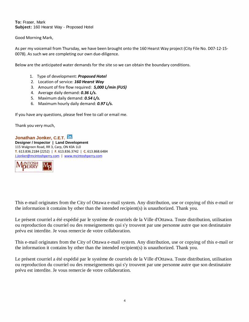
As per my voicemail from Thursday, we have been brought onto the 160 Hearst Way project (City File No. D07-12-15-0078). As such we are completing our own due-diligence.
Below are the anticipated water demands for the site so we can obtain the boundary conditions.
1. Type of development: Proposed Hotel2. Location of service: 160 Hearst Way3. Amount of fire flow required: 5,000 L/min (FUS)4. Average daily demand: 0.36 L/s.5. Maximum daily demand: 0.54 L/s.6. Maximum hourly daily demand: 0.97 L/s.
If you have any questions, please feel free to call or email me.
Thank you very much,
Jonathan Jonker, C.E.T.Designer / Inspector | Land Development115 Walgreen Road, RR 3, Carp, ON K0A 1L0T. 613.836.2184 (2252) | F. 613.836.3742 | C. [email protected] | www.mcintoshperry.com
This e-mail originates from the City of Ottawa e-mail system. Any distribution, use or copying of this e-mail orthe information it contains by other than the intended recipient(s) is unauthorized. Thank you.
Le présent courriel a été expédié par le système de courriels de la Ville d'Ottawa. Toute distribution, utilisationou reproduction du courriel ou des renseignements qui s'y trouvent par une personne autre que son destinataireprévu est interdite. Je vous remercie de votre collaboration.

Boundary Conditions at 160 Hearst Way (Kanata Hotel)
Information Provided: Date provided: 28 June 2016
Criteria Demand (L/s)
Average Demand 0.36
Maximum Daily Demand 0.54
Peak Hourly Demand 0.97
Fire Flow Demand 83.33
Maximum Daily + Fire Flow Demand 83.87
Location:
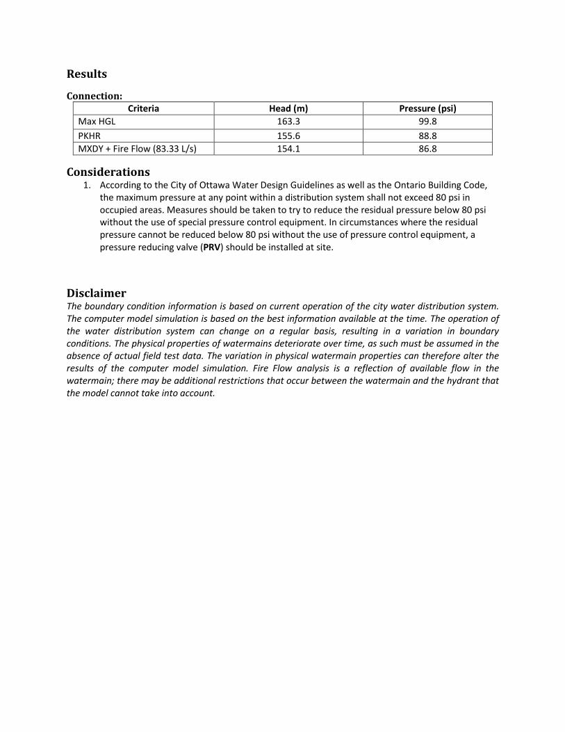
Results
Connection: Criteria Head (m) Pressure (psi)
Max HGL 163.3 99.8
PKHR 155.6 88.8
MXDY + Fire Flow (83.33 L/s) 154.1 86.8
Considerations 1. According to the City of Ottawa Water Design Guidelines as well as the Ontario Building Code,
the maximum pressure at any point within a distribution system shall not exceed 80 psi in occupied areas. Measures should be taken to try to reduce the residual pressure below 80 psi without the use of special pressure control equipment. In circumstances where the residual pressure cannot be reduced below 80 psi without the use of pressure control equipment, a pressure reducing valve (PRV) should be installed at site.
Disclaimer The boundary condition information is based on current operation of the city water distribution system. The computer model simulation is based on the best information available at the time. The operation of the water distribution system can change on a regular basis, resulting in a variation in boundary conditions. The physical properties of watermains deteriorate over time, as such must be assumed in the absence of actual field test data. The variation in physical watermain properties can therefore alter the results of the computer model simulation. Fire Flow analysis is a reflection of available flow in the watermain; there may be additional restrictions that occur between the watermain and the hydrant that the model cannot take into account.

APPENDIX C: SANITARY CALCULATIONS

SANITARY SEWER DESIGN SHEET
FLOW3 4 5 6 7 8 9 10 11 12 13 14 15 16 17 18 19 20 21 22 23 24 25 26 27 28 29 30 31 30 31
AREA PEAK PEAK FLOW DESIGN CAPACITY LENGTH DIA SLOPE VELOCITY FLOW VELOCITYFROM TO PEAK FLOW FLOW FLOW (full) DEPTH (actual)
MH MH FACTOR (L/s) IND CUM IND CUM IND CUM (L/s) (L/s) (m/s) (mm) (m/s) L/s (%)
MH 100A MH 101A 0.61 230.0 230.0 4.00 3.73 0.00 0.00 0.00 0.61 0.61 0.17 3.90 65.46 8.21 200 3.66 2.019 35.1 1.122 61.56 94.05MH 101A MH 102A 0.61 230.0 230.0 4.00 3.73 0.00 0.00 0.00 0.61 0.61 0.17 3.90 48.39 13.10 200 2.00 1.492 40.4 0.907 44.49 91.95
Design Parameters: Notes: JMJ No. 1. Mannings coefficient (n) = 0.013 1. 2. Demand (per capita): 350 L/day
SF 3.4 p/p/u Peak Factor 3. Infiltration allowance: 0.28 L/s/Ha CJMTH/SD 2.7 p/p/u INST 50,000 L/Ha/day 1.5 4. Residential Peaking Factor:
APT 2.3 p/p/u COM 50,000 L/Ha/day 1.5 Harmon Formula = 1+(14/(4+P^0.5))Other 60 p/p/Ha IND 35,000 L/Ha/day MOE Chart where P = population in thousands CP-16-0372
1 of 1
Project No.:Sheet No:Date:
2015-05-21
Checked:
Designed: Date2016-06-30
(L/s) (m) (mm) (%)CUM
RevisionISSUED FOR SITE PLAN CONTROL
AREA (ha) AREA (ha) AVAILABLE
Residential ICI Areas
SEWER DATA
CAPACITY
ICI AREAS INFILTRATION ALLOWANCE
INSTITUTIONAL COMMERCIALIND CUM INDINDUSTRIAL
RESIDENTIAL
SF SD (ha) (L/s)TH APT
Street No. 1Street No. 1
STREET AREA ID
A-1A-2
POPULATIONUNIT TYPES
PROJECT:LOCATION:
CLIENT:
160 Hearst WayOttawa
Diamond Jubilee Hospitality Inc.
LOCATION1 2
H:\01 Project - Proposals\2016 Jobs\CP\0CP-16-0372 Arif Shariff_Best Western Kanata_160 Hearst Way\Civil\03 - Servicing\Sanitary\CP-16-0372 - Sanitary Sewer Design Sheet.xlsx 2016-10-059:39 AM

115 Walgreen Road, R.R. 3, Carp, ON K0A 1L0 | T. 613.836.2184 | F. 613.836.3742
[email protected] | www.mcintoshperry.com
Project Name: 160 Hearst Way, Ottawa Best Western CP-16-0372 Re: Sanitary Flow Calculations
1. Building Occupancy The maximum number of bedroom units will be 69 units as per the floors plans and the attached unit break down from the Architect.
2. Daily Volume in Litres
As per the extract of the City of Ottawa Sewer Design Guidelines, Appendix 4-A; Daily Sewage Flow for Motels and Hotels
Residential portion with full housekeeping
= 225 Liters/Person/Day Non-Residential portion with dining room
= 125 Liters/seat/Day Non-Residential portion, non-resident staff
= 40 Liters/person/Day
3. Peak Flow (Q/p)
QBED(p) = FBED x PBED Where: FBED = 225 Litres/Person/Day (as per City of Ottawa Sewer Design Guidelines) PBED = 218 (max occupancy)
Therefore, QBED(p) = (225) x (218) = 49,050 L/Day (0.568 L/sec)
QSEAT(p) = FSEAT x PSEAT Where: FSEAT= 125 Litres/Seat/Day (as per City of Ottawa Sewer Design Guidelines) PSEAT = 44 Seats (as per floor plans)
Therefore, QSEAT(p) = (125) x (44) = 5,500 L/Day (0.064 L/sec)
QSTAFF(p) = FSTAFF x PSTAFF Where: FSTAFF= 40 Litres/Seat/Day (as per City of Ottawa Sewer Design Guidelines) PSTAFF = 12 Staff (as per Architect)
Therefore, QSTAFF(p) = (40) x (12) = 480 L/Day (0.006 L/sec)

115 Walgreen Road, R.R. 3, Carp, ON K0A 1L0 | T. 613.836.2184 | F. 613.836.3742 [email protected] | www.mcintoshperry.com
QTOTAL(p) = QBED+QSEAT+QSTAFF Where: QBED = 49,050 L/Day QSEAT = 5,500 L/Day QSTAFF = 480 L/Day
Therefore, QTOTAL(p) = (49,050) + (5,500) + (480) = 55,030 L/Day (0.637 L/sec) o QTOTAL(p) x peaking factor = design flow
QTOTAL X 4.0 = 2.55 L/s
The proposed site will have peak lows less than the original submission design and therefore it is anticipated that there will be no issues with capacity constraints within the existing sanitary main. Therefore, the existing 450mm diameter PVC sanitary main within Hearst Way and the proposed 200mm diameter lateral have the capacity to accommodate the new flows.

1
Jonathan Jonker
From: Paul Wright <[email protected]>Sent: July-04-16 12:18 PMTo: Jonathan JonkerCc: Linda Okum; Curtis Melanson; Elias J. ShomaliSubject: Jonathan - occupancy - BW GLo Kanata
Follow Up Flag: Follow upFlag Status: Flagged
HI Jonathan
Staff: 12 persons per day
Guests: we have 29 king rooms and 40 double queen rooms so total 69 rooms. I am not sure how you would calculateas typically for Code it is 2 per room so 138 persons at 100% occupancy which is rare we typically assume 60%occupancy to break even. But also if you say has 2 per king bed and 4 per double queen room then that maximizes at218 which would be a very rare occurrence.
Thanks for letting us know about the manager change.
How far off are you ?
CheersPaul
Paul Wright BA Hons. Dipl. Arch, OAA, M.A.A., NSAA, MRAIC
ACI Wright Architects Inc.Manitoba, Ontario, Nova Scotia2171 Avenue Rd., Suite 204, Toronto, ON M5M 4B4T: (416) 322-2132 F: (416) 850-4356 www.aciw.caE:[email protected]
This message may contain confidential and/or privileged information. If you are not the addressee or authorized to receive this for the addressee,you must not use, copy, disclose or take any action based on this message or any information herein. If you have received this message in error,please advise the sender immediately by reply e-mail and delete this message. Thank you for your cooperation.
From: Jonathan Jonker [mailto:[email protected]]Sent: Monday, July 4, 2016 10:56 AMTo: Paul Wright <[email protected]>Cc: Linda Okum <[email protected]>; Curtis Melanson <[email protected]>Subject: RE: Curtis - average grade issue - BW GLo Kanata


APPENDIX D: PRE-DEVELOPEMENT PLAN

Date
Do not scale drawings
No.
before proceeding with the workCheck and verify all dimensions
Revision/Issue
Project:
Project Number:
Drawing Number:
Drawing Title:
Checked By:
Drawn by:
Date:
Designed By:
Client:
SHEET of
Stamp: Stamp:

Date
Do not scale drawings
No.
before proceeding with the work
Check and verify all dimensions
Revision/Issue
Project:
Project Number:
Drawing Number:
Drawing Title:
Checked By:
Drawn by:
Date:
Designed By:
Client:
SHEET of
FILE
NAM
E: H
:\01
Pro
ject
- Pr
opos
als\
2016
Jobs
\CP\
0CP-
16-0
372
Arif
Shar
iff_B
est W
este
rn K
anat
a_16
0 He
arst
Way
\Civ
il\15
- Dr
awin
gs\0
CP-1
6-03
72 -
PRES
ENTA
TIO
N.d
wg
LAST
SAV
ED: T
hurs
day,
Sep
tem
ber 0
1, 2
016
LAS
T SA
VED
BY: j
.jonk
erLA
ST P
LOTT
ED: T
hurs
day,
Sep
tem
ber 0
8, 2
016
CTB
FIL
E U
SED:
----
Stamp: Stamp:
Scale:
ARIF SHARIFF - DIAMOND JUBILEE HOSPITALITY INC.4020 OTTER TRAIL CT. P:613-769-1143OTTAWA, ON, K1V 1R1 F:613-822-1913
PROPOSED HOTELBEST WESTERN
160 HEARST WAY
OTTAWA ON
PRE-DEVELOPMENT DRAINAGE PLAN
JMJ
CJM/RPK
JMJ
N.T.S.
JUNE 23, 2016
0CP-16-0372
1 1 PRE
1 ISSUED FOR SITE PLAN CONTROL JUL 04, 2016
02 REVISED AS PER CITY COMMENTS SEP 08, 2016
LOCATION PLAN
SUBJECT LOCATION
HEARST WAY
COHE
N A
VE.
ANGU
S DR
.
HIGHWAY 417
EAGLESON RD.
LEGEND
AREA SIZE(HECTARES)
AREA
5-YR RUNOFFCOEFFICIENT
100-YR RUNOFFCOEFFICIENT

APPENDIX E: POST-DEVELOPMENT PLAN
Date
Do not scale drawings
No.
before proceeding with the workCheck and verify all dimensions
Revision/Issue
Project:
Project Number:
Drawing Number:
Drawing Title:
Checked By:
Drawn by:
Date:
Designed By:
Client:
SHEET of
Stamp: Stamp:
Date
Do not scale drawings
No.
before proceeding with the work
Check and verify all dimensions
Revision/Issue
Project:
Project Number:
Drawing Number:
Drawing Title:
Checked By:
Drawn by:
Date:
Designed By:
Client:
SHEET of
FILE
NAM
E: H
:\01
Pro
ject
- Pr
opos
als\
2016
Jobs
\CP\
0CP-
16-0
372
Arif
Shar
iff_B
est W
este
rn K
anat
a_16
0 He
arst
Way
\Civ
il\15
- Dr
awin
gs\0
CP-1
6-03
72 -
PRES
ENTA
TIO
N.d
wg
LAST
SAV
ED: T
hurs
day,
Sep
tem
ber 0
1, 2
016
LAS
T SA
VED
BY: j
.jonk
erLA
ST P
LOTT
ED: T
hurs
day,
Sep
tem
ber 0
8, 2
016
CTB
FIL
E U
SED:
----
Stamp: Stamp:
Scale:
ARIF SHARIFF - DIAMOND JUBILEE HOSPITALITY INC.4020 OTTER TRAIL CT. P:613-769-1143OTTAWA, ON, K1V 1R1 F:613-822-1913
PROPOSED HOTELBEST WESTERN
160 HEARST WAY
OTTAWA ON
POST-DEVELOPMENT DRAINAGE PLAN
JMJ
CJM/RPK
JMJ
N.T.S.
JUNE 23, 2016
0CP-16-0372
1 1 POST
1 ISSUED FOR SITE PLAN CONTROL JUL 04, 2016
02 REVISED AS PER CITY COMMENTS SEP 08, 2016
LOCATION PLAN
SUBJECT LOCATION
HEARST WAY
COHE
N A
VE.
ANGU
S DR
.
HIGHWAY 417
EAGLESON RD.
LEGEND
AREA SIZE(HECTARES)
AREA
5-YR RUNOFFCOEFFICIENT
100-YR RUNOFFCOEFFICIENT

APPENDIX F: STORMWATER CALCULATIONS

Pg 1 of 78-Sep-16
AVERAGE PRE-DEVELOPMENT RUNOFF COEFFICIENT CALCULATIONS
Area A1Type C (5-yr) C (100-yr) Area (m²) Product (5-yr) Product (100-yr)
GRASS 0.20 0.25 6068.4 1213.7 1517.1Avg C 0.20 0.25
Area B1Type C (5-yr) C (100-yr) Area (m²) Product (5-yr) Product (100-yr)
GRASS 0.20 0.25 1785.0 357.0 446.3Avg C 0.20 0.25
Area B2Type C (5-yr) C (100-yr) Area (m²) Product (5-yr) Product (100-yr)
BUILDING 0.90 1.00 924.6 832.1 924.6Avg C 0.90 1.00
Area B3Type C (5-yr) C (100-yr) Area (m²) Product (5-yr) Product (100-yr)
ASPHALT 0.90 1.00 374.637 337.2 374.6CONCRETE 0.90 1.00 81.07 73.0 81.1
GRASS 0.20 0.25 89.491 17.9 22.4Avg C 0.79 0.88
Area B4Type C (5-yr) C (100-yr) Area (m²) Product (5-yr) Product (100-yr)
ASPHALT 0.90 1.00 325.389 292.9 325.4CONCRETE 0.90 1.00 52.01 46.8 52.0
GRASS 0.20 0.25 15.980 3.2 4.0Avg C 0.87 0.97
Area B5Type C (5-yr) C (100-yr) Area (m²) Product (5-yr) Product (100-yr)
ASPHALT 0.90 1.00 364.253 327.8 364.3CONCRETE 0.90 1.00 54 48.6 54.0
Avg C 0.90 1.00
Area B6Type C (5-yr) C (100-yr) Area (m²) Product (5-yr) Product (100-yr)
ASPHALT 0.90 1.00 1146.182 1031.6 1146.2CONCRETE 0.90 1.00 113.4 102.1 113.4
GRASS 0.20 0.25 64.072 12.8 16.0Avg C 0.87 0.96
Area B7Type C (5-yr) C (100-yr) Area (m²) Product (5-yr) Product (100-yr)
CONCRETE 0.90 1.00 34.86 31.4 34.9GRASS 0.20 0.25 643.492 128.7 160.9Avg C 0.24 0.29
SOUTH SIDE OF SITE - DRAINS UN-RESTRICTED MH#1
EXISTING SITE
WEST CORNER - DRAINS TO CBMH#4
SOUTH CORNER OF SITE - DRAINS TO CBMH#3
CP-16-0372 - 160 HEARST WAY, SWM CALCULATIONS
PROPOSED ROOF - DRAINS TO MH#1
AVERAGE POST-DEVELOPMENT RUNOFF COEFFICIENT CALCULATIONS
NORTH AND WEST SIDE OF SITE - UN-RESTRICTED FLOW
NORTH WEST SIDE - DRAINS TO CBMH#5
NORTH CORNER OF SITE - DRAINS TO CB#6

Pg 2 of 78-Sep-16
Time ofconcentration (min.)
5-Year (mm/hr) 100-Year (mm/hr)
20.00 69.9 104.2 PRE-DEVELOPMENT (As per Kanata Report)10.00 104.2 178.6
A1 0.61 0.20 0.25 23.6 43.9Total 0.61 #REF! #REF! 23.6 43.9
B1 0.18 0.20 0.25 10.3 22.2B2 0.09 0.90 1.00 24.1 45.9B3 0.05 0.79 0.88 12.5 23.8B4 0.04 0.87 0.97 9.9 18.9B5 0.04 0.90 1.00 10.9 20.8B6 0.13 0.87 0.96 33.4 63.1B7 0.07 0.24 0.29 4.7 9.8
Total 0.61 0.601947646 0.6785714 105.8 204.4
A1 0.61 0.70 82.5
5-yr 100-yr 5-yr 100-yrB1 10.3 22.2 10.3 22.2 UNRESTRICTEDB2 24.1 45.9 3.00 4.80B3 12.5 23.8B4 9.9 18.9B5 10.9 20.8B6 33.4 63.1B7 4.7 9.8 4.7 9.8 UNRESTRICTED
Total 105.8 204.4 63.8 82.5
Balanced RunoffCoefficient (C) 5-
yr
Balanced RunoffCoefficient (C)
100-yr
ACTUAL STORM WATER RUNOFF FROM SITE (L/s)
5-Year Flow Rate(l/s)
RESTRICTED45.8 45.8
CP-16-0372 - 160 HEARST WAY, SWM CALCULATIONS
Drainage Area(ha)
Balanced RunoffCoefficient (C) 5-
yr
POST-DEVELOPMENT RUNOFF COEFFICIENT CALCULATIONS
5-Year Flow Rate(l/s)
100-Year FlowRate (l/s)
5-Year Flow Rate(l/s)
PRE-DEVELOPMENT RUNOFF COEFFICIENT CALCULATIONS
Basin
Drainage Area(ha)
POST-DEVELOPMENT (As per OSDG)
Basin
Post-Development Unrestricted (l/s) Post-Development (Restricted) (l/s)
Balanced RunoffCoefficient (C)
100-yr
100-Year FlowRate (l/s)
Basin
Drainage Area(ha)
Balanced RunoffCoefficient (C) 5-
yr
REQUIRED RESTRICTED FLOW ('C' of 0.7)
Area

Pg 3 of 78-Sep-16
5 141.2 32.7 3.0 29.7 8.910 104.2 24.1 3.0 21.1 12.715 83.6 19.3 3.0 16.3 14.720 70.3 16.3 3.0 13.3 15.925 60.9 14.1 3.0 11.1 16.630 53.9 12.5 3.0 9.5 17.035 48.5 11.2 3.0 8.2 17.340 44.2 10.2 3.0 7.2 17.345 40.6 9.4 3.0 6.4 17.350 37.7 8.7 3.0 5.7 17.255 35.1 8.1 3.0 5.1 16.960 32.9 7.6 3.0 4.6 16.665 31.0 7.2 3.0 4.2 16.370 29.4 6.8 3.0 3.8 16.075 27.9 6.5 3.0 3.5 15.5
Maximum Storage Required (m³) = 17.3
5 242.7 62.4 4.8 57.6 17.310 178.6 45.9 4.8 41.1 24.715 142.9 36.7 4.8 31.9 28.720 120.0 30.8 4.8 26.0 31.325 103.8 26.7 4.8 21.9 32.830 91.9 23.6 4.8 18.8 33.935 82.6 21.2 4.8 16.4 34.540 75.1 19.3 4.8 14.5 34.845 69.1 17.8 4.8 13.0 35.050 64.0 16.5 4.8 11.7 35.055 59.6 15.3 4.8 10.5 34.760 55.9 14.4 4.8 9.6 34.465 52.6 13.5 4.8 8.7 34.070 49.8 12.8 4.8 8.0 33.675 47.3 12.2 4.8 7.4 33.180 45.0 11.6 4.8 6.8 32.5
35.0
N/ALocation T/G INV. (out) Area (m2) Depth (m) Volume (m3)
ROOF N/A N/A 924.59 0.025 23.1Total 23.1
23.117.3
N/ALocation T/G INV. (out) Area (m2) Depth (m) Volume (m3)
ROOF N/A N/A 924.59 0.040 37.0Total 37.0
37.035.0
Maximum Storage Required (m³) =
STORAGE OCCUPIED IN AREA B2
Other Storage Areas on Site Water Elev. (m) = 5-YEAR STORM EVENT
Storage Available (m³) =Storage Required (m³) =
100-YEAR STORM EVENTOther Storage Areas on Site Water Elev. (m) =
Storage Available (m³) =Storage Required (m³) =
100-YEAR STORM EVENT
Tc I (mm/hr) Runoff (l/s) B2Allowable
Outflow (l/s)Runoff To BeStored (l/s)
Storage Required(m3)
CP-16-0372 - 160 HEARST WAY, SWM CALCULATIONS
5-YEAR STORM EVENT
Tc I (mm/hr) Runoff (l/s) B2Allowable
Outflow (l/s)Runoff To BeStored (l/s)
Storage Required(m3)
STORAGE REQUIRMENTS FOR AREA B2
Pg 4 of 78-Sep-16
5 141.2 16.9 13.4 14.8 45.2 22.9 67.4 20.210 104.2 12.5 9.9 10.9 33.4 22.9 43.8 26.315 83.6 10.0 8.0 8.7 26.8 22.9 30.6 27.520 70.3 8.4 6.7 7.4 22.5 22.9 22.1 26.525 60.9 7.3 5.8 6.4 19.5 22.9 16.1 24.130 53.9 6.5 5.1 5.6 17.3 22.9 11.6 20.935 48.5 5.8 4.6 5.1 15.5 22.9 8.1 17.140 44.2 5.3 4.2 4.6 14.2 22.9 5.4 12.945 40.6 4.9 3.9 4.2 13.0 22.9 3.1 8.350 37.7 4.5 3.6 3.9 12.1 22.9 1.2 3.7
Maximum Storage Required (m³) = 27.5
5 242.7 32.4 25.7 28.2 85.7 22.9 149.2 44.810 178.6 23.8 18.9 20.8 63.1 22.9 103.7 62.215 142.9 19.1 15.2 16.6 50.5 22.9 78.4 70.620 120.0 16.0 12.7 14.0 42.4 22.9 62.2 74.625 103.8 13.8 11.0 12.1 36.7 22.9 50.7 76.130 91.9 12.3 9.7 10.7 32.5 22.9 42.3 76.135 82.6 11.0 8.8 9.6 29.2 22.9 35.7 74.940 75.1 10.0 8.0 8.7 26.5 22.9 30.4 72.945 69.1 9.2 7.3 8.0 24.4 22.9 26.1 70.550 64.0 8.5 6.8 7.4 22.6 22.9 22.5 67.5
76.1
94.25Location T/G INV. (out) Area (m2) Depth (m) Volume (m3)CBMH#3 94.10 91.85 92.69 0.15 4.6CBMH#4 94.10 92.00 133.29 0.15 7.7CBMH#5 94.10 92.20 176.75 0.15 8.8
CB#6 94.10 92.40 132.76 0.15 6.6Total 27.8
27.827.5
94.32Location T/G INV. (out) Area (m2) Depth (m) Volume (m3)CBMH#3 94.10 91.85 204.61 0.22 14.7CBMH#4 94.10 92.00 244.47 0.22 20.1CBMH#5 94.10 92.20 300.46 0.22 25.6
CB#6 94.10 92.40 284.81 0.22 21.9Total 82.2
82.276.1
5-YEAR STORM EVENT
STORAGE OCCUPIED IN AREA B3-B6
Water Elev. (m) =Other Storage Areas on Site
Water Elev. (m) =
Storage Available (m³) =
Other Storage Areas on Site
Storage Required (m³) =
Storage Required (m³) =
100-YEAR STORM EVENT
Storage Available (m³) =
Maximum Storage Required (m³) =
Tc I (mm/hr) Runoff (l/s) B3Allowable
Outflow (l/s)
STORAGE REQUIRMENTS FOR AREA B3-B6
5-YEAR STORM EVEN, Allowable flow rate has been halved as per City requirements.
Runoff (l/s) B5 Runoff (l/s) B6
Runoff (l/s) B5
StorageRequired (m3)
100-YEAR STORM EVENT, Allowable flow rate has been halved as per City requirements.
Runoff (l/s) B4
StorageRequired (m3)
Tc I (mm/hr) Runoff (l/s) B3Allowable
Outflow (l/s)
Runoff To BeStored (l/s)
Runoff (l/s) B4Runoff To BeStored (l/s)
CP-16-0372 - 160 HEARST WAY, SWM CALCULATIONS
Runoff (l/s) B6

Pg 5 of 75-May-14
0.18 15 1.800.24 20 2.40
Depth (mm) Flow (L/s) 0.30 25 3.0015 0.18 0.36 30 3.6020 0.24 0.42 35 4.2025 0.30 0.48 40 4.8030 0.36 0.54 45 5.4035 0.42 0.60 50 6.0040 0.48 0.66 55 6.6045 0.54 0.72 60 7.2050 0.60 0.78 65 7.80
*Roof Drain model to be Accutrol Weirs, See attached sheets 0.84 70 8.40*Roof Drain Flow information taken from Watts Drainage website 0.90 75 9.00
0.96 80 9.601.02 85 10.20
1 roof drain during a 5 year storm 1.08 90 10.80elevation of water = 25mm 1.14 95 11.40Flow leaving 1 roof drain = (1 x 0.30 L/s) = 0.30 L/s 1.20 100 12.00
1.26 105 12.601 roof drain during a 100 year storm 1.32 110 13.20elevation of water = 45mm 1.38 115 13.80Flow leaving 1 roof drain = (1 x 0.54 L/s) = 0.54 L/s 1.44 120 14.40
1.50 125 15.0010 roof drains during a 5 year storm 1.56 130 15.60elevation of water = 25mm 1.62 135 16.20Flow leaving 10 roof drains = (10 x 0.30 L/s) = 3.00 L/s 1.68 140 16.80
1.74 145 17.4010 roof drains during a 100 year storm 1.80 150 18.00elevation of water = 45mmFlow leaving 10 roof drains = (10 x 0.54 L/s) = 5.40 L/s
(One Weir)Metric
CALCULATING ROOF FLOW
Note: The flow leaving through a restricted roof drain is basedon flow vs. head information
CP-16-0372 - 160 HEARST WAY, SWM CALCULATIONS
ROOF DRAIN FLOW (B2) Roof Drain Flow
Flow (l/s) Storage Depth (mm)10 Roof Drains
Flow (l/s)Flow Rate Vs. Build-Up

Pg 6 of 78-Sep-2016CP-16-0372 - 160 HEARST WAY, SWM CALCULATIONS
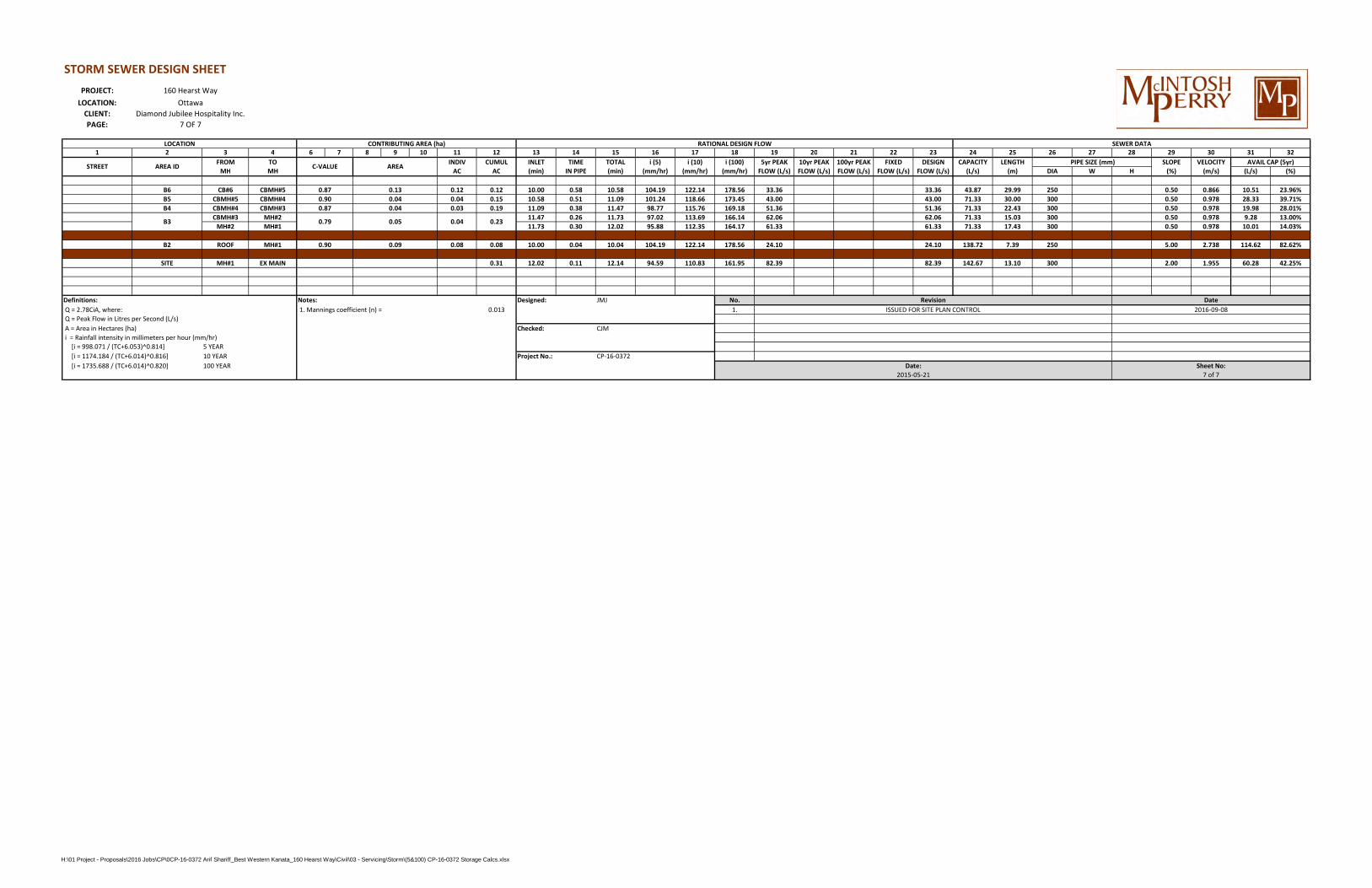
STORM SEWER DESIGN SHEETPROJECT:
LOCATION:CLIENT:PAGE:
1 2 3 4 6 7 8 9 10 11 12 13 14 15 16 17 18 19 20 21 22 23 24 25 26 27 28 29 30 31 32FROM TO INDIV CUMUL INLET TIME TOTAL i (5) i (10) i (100) 5yr PEAK 10yr PEAK 100yr PEAK FIXED DESIGN CAPACITY LENGTH SLOPE VELOCITY
MH MH AC AC (min) IN PIPE (min) (mm/hr) (mm/hr) (mm/hr) FLOW (L/s) FLOW (L/s) FLOW (L/s) FLOW (L/s) FLOW (L/s) (L/s) (m) DIA W H (%) (m/s) (L/s) (%)
B6 CB#6 CBMH#5 0.12 0.12 10.00 0.58 10.58 104.19 122.14 178.56 33.36 33.36 43.87 29.99 250 0.50 0.866 10.51 23.96%B5 CBMH#5 CBMH#4 0.04 0.15 10.58 0.51 11.09 101.24 118.66 173.45 43.00 43.00 71.33 30.00 300 0.50 0.978 28.33 39.71%B4 CBMH#4 CBMH#3 0.03 0.19 11.09 0.38 11.47 98.77 115.76 169.18 51.36 51.36 71.33 22.43 300 0.50 0.978 19.98 28.01%
CBMH#3 MH#2 11.47 0.26 11.73 97.02 113.69 166.14 62.06 62.06 71.33 15.03 300 0.50 0.978 9.28 13.00%MH#2 MH#1 11.73 0.30 12.02 95.88 112.35 164.17 61.33 61.33 71.33 17.43 300 0.50 0.978 10.01 14.03%
B2 ROOF MH#1 0.08 0.08 10.00 0.04 10.04 104.19 122.14 178.56 24.10 24.10 138.72 7.39 250 5.00 2.738 114.62 82.62%
SITE MH#1 EX MAIN 0.31 12.02 0.11 12.14 94.59 110.83 161.95 82.39 82.39 142.67 13.10 300 2.00 1.955 60.28 42.25%
Definitions: Notes: JMJ No. Q = 2.78CiA, where: 1. Mannings coefficient (n) = 0.013 1. Q = Peak Flow in Litres per Second (L/s) A = Area in Hectares (ha) CJM i = Rainfall intensity in millimeters per hour (mm/hr) [i = 998.071 / (TC+6.053)^0.814] 5 YEAR [i = 1174.184 / (TC+6.014)^0.816] 10 YEAR CP-16-0372 [i = 1735.688 / (TC+6.014)^0.820] 100 YEAR
0.04 0.23B3
CONTRIBUTING AREA (ha)
160 Hearst WayOttawa
Diamond Jubilee Hospitality Inc.7 OF 7
LOCATION
0.87 0.130.90 0.040.87
RATIONAL DESIGN FLOW SEWER DATA
STREET AREA ID C-VALUE AREA PIPE SIZE (mm) AVAIL CAP (5yr)
0.04
0.90 0.09
0.79 0.05
Designed: Revision DateISSUED FOR SITE PLAN CONTROL 2016-09-08
Checked:
Project No.:Date: Sheet No:
2015-05-21 7 of 7
H:\01 Project - Proposals\2016 Jobs\CP\0CP-16-0372 Arif Shariff_Best Western Kanata_160 Hearst Way\Civil\03 - Servicing\Storm\(5&100) CP-16-0372 Storage Calcs.xlsx


APPENDIX G: QUALITY TREATMENT UNIT DESIGN DETAILS

1
Jonathan Jonker
From: Stratford, Hal <[email protected]>Sent: June-29-16 1:51 PMTo: Jonathan JonkerSubject: RE: 160 Hearst Way, City of Ottawa - Quality Treatment Unit SizingAttachments: 6-29-macintosh.pdf; Stormceptor DATA-JAN 2016.xlsx
STC-300 $16,564
Flow rate before bypass is 9 LPS
For the newest version of PCSWMM please visit the Imbrium website atwww.imbriumsystems.com
Hal StratfordStormwater SpecialistCambridge PlantPhone 888-888-3222 ext-238Cell [email protected] the water for future generations
(We have changed our name from Hanson to Forterra)
From: Jonathan Jonker [mailto:[email protected]]Sent: Wednesday, June 29, 2016 1:38 PMTo: Stratford, HalSubject: 160 Hearst Way, City of Ottawa - Quality Treatment Unit Sizing
Good Afternoon Hal,
We have a site located at 160 Hearst Way that is being developed into hotel. The City and Conservation Authority hasstipulated 70% TSS removal, there is limited room on the site for treatment using natural features therefore we willneed a Quality treatment unit. Please find below site parameters for the sizing and structure costs.
Site Parameters:Location: 160 Hearst Way, OttawaTotal Area: 0.61% Impervious: 57% ImperviousNeed 70% TSS
Site Flows:Flow (100yr Stm) = 46.3 L/s

2
Flow (5yr Stm) = 46.3 L/s*Please note that the Quality treatment unit will be downstream of the site restriction, and the flows provided includethe restricted flows that will be leaving the site through the unit.C Value for 5yr = 0.60C Value for 100yr = 0.68
We will require:The units Treatment flow rateOil CapacitySediment CapacityTotal Holding CapacityStructure cost
Thank you very much,
Jonathan Jonker, C.E.T.Designer / Inspector | Land Development115 Walgreen Road, RR 3, Carp, ON K0A 1L0T. 613.836.2184 (2252) | F. 613.836.3742 | C. [email protected] | www.mcintoshperry.com

Stormceptor Detailed Sizing Report – Page 1 of 7
Detailed Stormceptor Sizing Report – 160 Hearst Way
Project Information & Location
Project Name 160 Hearst Way Project Number 1363
City Ottawa State/ Province Ontario
Country Canada Date 6/29/2016
Designer Information EOR Information (optional)
Name HAL STRATFORD Name Jonathan J
Company FORTERRA Company Macintosh Perry
Phone # 226-220-3943 Phone #
Email [email protected] Email
Stormwater Treatment Recommendation
The recommended Stormceptor Model(s) which achieve or exceed the user defined water quality objective for each site within the project are listed in the below Sizing Summary table.
Site Name
Recommended Stormceptor Model STC 300
Target TSS Removal (%) 70.0
TSS Removal (%) Provided 76
PSD Fine Distribution
Rainfall Station OTTAWA MACDONALD-CARTIER INT'L A
The recommended Stormceptor model achieves the water quality objectives based on the selected inputs, historical rainfall records and selected particle size distribution.
Stormceptor Sizing Summary
Stormceptor Model % TSS Removal Provided
% Runoff Volume Captured Provided
STC 300 76 91
STC 750 84 97
STC 1000 85 97
STC 1500 85 97
STC 2000 87 99
STC 3000 89 99
STC 4000 91 100
STC 5000 92 100
STC 6000 93 100
STC 9000 95 100
STC 10000 95 100
STC 14000 96 100
Stormceptor MAX Custom Custom

Stormceptor Detailed Sizing Report – Page 2 of 7
Stormceptor The Stormceptor oil and sediment separator is sized to treat stormwater runoff by removing pollutants through gravity separation and flotation. Stormceptor’s patented design generates positive TSS removal for each rainfall event, including large storms. Significant levels of pollutants such as heavy metals, free oils and nutrients are prevented from entering natural water resources and the re-suspension of previously captured sediment (scour) does not occur. Stormceptor provides a high level of TSS removal for small frequent storm events that represent the majority of annual rainfall volume and pollutant load. Positive treatment continues for large infrequent events, however, such events have little impact on the average annual TSS removal as they represent a small percentage of the total runoff volume and pollutant load. Design Methodology Stormceptor is sized using PCSWMM for Stormceptor, a continuous simulation model based on US EPA SWMM. The program calculates hydrology using local historical rainfall data and specified site parameters. With US EPA SWMM’s precision, every Stormceptor unit is designed to achieve a defined water quality objective. The TSS removal data presented follows US EPA guidelines to reduce the average annual TSS load. The Stormceptor’s unit process for TSS removal is settling. The settling model calculates TSS removal by analyzing: • Site parameters • Continuous historical rainfall data, including duration, distribution, peaks & inter-event dry periods • Particle size distribution, and associated settling velocities (Stokes Law, corrected for drag) • TSS load • Detention time of the system
Hydrology Analysis
PCSWMM for Stormceptor calculates annual hydrology with the US EPA SWMM and local continuous historical rainfall data. Performance calculations of Stormceptor are based on the average annual removal of TSS for the selected site parameters. The Stormceptor is engineered to capture sediment particles by treating the required average annual runoff volume, ensuring positive removal efficiency is maintained during each rainfall event, and preventing negative removal efficiency (scour). Smaller recurring storms account for the majority of rainfall events and average annual runoff volume, as observed in the historical rainfall data analyses presented in this section.
Rainfall Station
State/Province Ontario Total Number of Rainfall Events 4093
Rainfall Station Name OTTAWA MACDONALD-CARTIER INT'L A Total Rainfall (mm) 20978.1
Station ID # 6000 Average Annual Rainfall (mm) 567.0
Coordinates 45°19'N, 75°40'W Total Evaporation (mm) 1946.3
Elevation (ft) 370 Total Infiltration (mm) 8985.1
Years of Rainfall Data 37 Total Rainfall that is Runoff 10046.7
Notes
• Stormceptor performance estimates are based on simulations using PCSWMM for Stormceptor, which uses the EPA Rainfall and Runoff modules. • Design estimates listed are only representative of specific project requirements based on total suspended solids (TSS) removal defined by the selected PSD, and based on stable site conditions only, after construction is completed. • For submerged applications or sites specific to spill control, please contact your local Stormceptor representative for further design assistance.

Stormceptor Detailed Sizing Report – Page 3 of 7
Up Stream Storage
Storage (ha-m) Discharge (cms)
0.000 0.000
Drainage Area
Total Area (ha) 0.61
Imperviousness % 57.0
Up Stream Flow Diversion
Max. Flow to Stormceptor (cms) 0.00000
Water Quality Objective
TSS Removal (%) 70.0
Runoff Volume Capture (%) 85.00
Oil Spill Capture Volume (L)
Peak Conveyed Flow Rate (L/s)
Water Quality Flow Rate (L/s)
Design Details
Stormceptor Inlet Invert Elev (m)
Stormceptor Outlet Invert Elev (m)
Stormceptor Rim Elev (m)
Normal Water Level Elevation (m)
Pipe Diameter (mm)
Pipe Material
Multiple Inlets (Y/N) No
Grate Inlet (Y/N) No
Particle Size Distribution (PSD)
Removing the smallest fraction of particulates from runoff ensures the majority of pollutants, such as metals, hydrocarbons and nutrients are captured. The table below identifies the Particle Size
Distribution (PSD) that was selected to define TSS removal for the Stormceptor design.
Fine Distribution
Particle Diameter (microns)
Distribution % Specific Gravity
20.0 20.0 1.30
60.0 20.0 1.80
150.0 20.0 2.20
400.0 20.0 2.65
2000.0 20.0 2.65

Stormceptor Detailed Sizing Report – Page 4 of 7
Site Name
Site Details
Drainage Area
Total Area (ha) 0.61
Imperviousness % 57.0
Infiltration Parameters
Horton’s equation is used to estimate infiltration
Max. Infiltration Rate (mm/hr) 76.2
Min. Infiltration Rate (mm/hr) 13.2
Decay Rate (1/sec) 0.00115
Regeneration Rate (1 /sec) 0.01
Surface Characteristics
Width (m) 156.00
Slope % 2
Impervious Depression Storage (mm) 1.57
Pervious Depression Storage (mm) 4.67
Impervious Manning’s n 0.015
Pervious Manning’s n 0.25
Evaporation
Daily Evaporation Rate (mm/day) 2.54
Dry Weather Flow
Dry Weather Flow (lps) 0
Winter Months
Winter Infiltration 0
Maintenance Frequency
Maintenance Frequency (months) > 12
TSS Loading Parameters
TSS Loading Function Build Up/ Wash-off
Buildup/Wash -off Parameters
Target Event Mean Conc. (EMC) mg/L 125
Exponential Buildup Power 0.40
Exponential Washoff Exponent 0.20
TSS Availability Parameters
Availability Constant A 0.05
Availability Factor B 0.04
Availability Exponent C 1.10
Min. Particle Size Affected by Availability (micron)
400

Stormceptor Detailed Sizing Report – Page 5 of 7
Cumulative Runoff Volume by Runoff Rate
Runoff Rate (L/s) Runoff Volume (m³) Volume Over (m³) Cumulative Runoff Volume (%)
1 25.194 36.564 40.8
4 47.945 13.811 77.6
9 55.92 5.836 90.6
16 59.207 2.547 95.9
25 60.661 1.094 98.2
36 61.347 0.408 99.3
49 61.643 0.112 99.8
64 61.735 0.02 100.0
81 61.755 0 100.0
100 61.755 0 100.0

Stormceptor Detailed Sizing Report – Page 6 of 7
Rainfall Event Analysis Rainfall Depth
(mm) No. of Events Percentage of Total
Events (%) Total Volume (mm) Percentage of Annual
Volume (%)
6.35 3113 76.1 5230 24.9
12.70 501 12.2 4497 21.4
19.05 225 5.5 3469 16.5
25.40 105 2.6 2317 11.0
31.75 62 1.5 1765 8.4
38.10 35 0.9 1206 5.8
44.45 28 0.7 1163 5.5
50.80 12 0.3 557 2.7
57.15 7 0.2 378 1.8
63.50 1 0.0 63 0.3
69.85 1 0.0 64 0.3
76.20 1 0.0 76 0.4
82.55 0 0.0 0 0.0
88.90 1 0.0 84 0.4
95.25 0 0.0 0 0.0
101.60 0 0.0 0 0.0
107.95 0 0.0 0 0.0
114.30 1 0.0 109 0.5
120.65 0 0.0 0 0.0
127.00 0 0.0 0 0.0
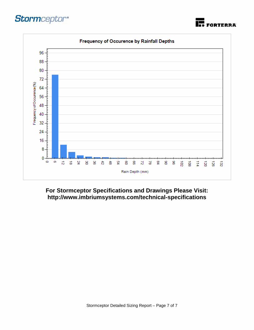
Stormceptor Detailed Sizing Report – Page 7 of 7
For Stormceptor Specifications and Drawings Please Visit: http://www.imbriumsystems.com/technical-specifications

APPENDIX H: CITY OF OTTAWA CHECKLIST

160 Hearst Way Proposed Hotel
1
CP-16-0372 Site Servicing & Stormwater Management Report
City of Ottawa
4. Development Servicing Study Checklist
The following section describes the checklist of the required content of servicing studies. It is expected that the proponent will address each one of the following items for the study to be deemed complete and ready for review by City of Ottawa Infrastructure Approvals staff.
The level of required detail in the Servicing Study will increase depending on the type of application. For example, for Official Plan amendments and re-zoning applications, the main issues will be to determine the capacity requirements for the proposed change in land use and confirm this against the existing capacity constraint, and to define the solutions, phasing of works and the financing of works to address the capacity constraint. For subdivisions and site plans, the above will be required with additional detailed information supporting the servicing within the development boundary.
4.1 General Content
Criteria Location (if applicable)
Executive Summary (for larger reports only). N/A
Date and revision number of the report. On Cover
Location map and plan showing municipal address, boundary, and layout of proposed development.
Appendix ‘E’
Plan showing the site and location of all existing services. Existing Conditions Plan
Development statistics, land use, density, adherence to zoning and official plan, and reference to applicable subwatershed and watershed plans that provide context to which individual developments must adhere.
1.1 Purpose
1.2 Site Description
6.0 Stormwater Management
Summary of Pre-consultation Meetings with City and other approval agencies.
Appendix ‘A’
Reference and confirm conformance to higher level studies and reports (Master Servicing Studies, Environmental Assessments, Community Design Plans), or in the case where it is not in conformance, the proponent must provide justification and
1.1 Purpose
1.2 Site Description
6.0 Stormwater Management

160 Hearst Way Proposed Hotel
2
CP-16-0372 Site Servicing & Stormwater Management Report
develop a defendable design criteria.
Statement of objectives and servicing criteria. 3.0 Pre-Consultation Summary
Identification of existing and proposed infrastructure available in the immediate area.
N/A
Identification of Environmentally Significant Areas, watercourses and Municipal Drains potentially impacted by the proposed development (Reference can be made to the Natural Heritage Studies, if available).
Lot Grading, Drainage Plan & sediment Control Plan
Concept level master grading plan to confirm existing and proposed grades in the development. This is required to confirm the feasibility of proposed stormwater management and drainage, soil removal and fill constraints, and potential impacts to neighbouring properties. This is also required to confirm that the proposed grading will not impede existing major system flow paths.
Lot Grading, Drainage Plan & sediment Control Plan
Identification of potential impacts of proposed piped services on private services (such as wells and septic fields on adjacent lands) and mitigation required to address potential impacts.
N/A
Proposed phasing of the development, if applicable. N/A
Reference to geotechnical studies and recommendations concerning servicing.
See Geotech
All preliminary and formal site plan submissions should have the following information:
o Metric scale o North arrow (including construction North) o Key plan o Name and contact information of applicant and property
owner o Property limits including bearings and dimensions o Existing and proposed structures and parking areas o Easements, road widening and rights-of-way o Adjacent street names
Lot Grading, Drainage Plan & sediment Control Plan

160 Hearst Way Proposed Hotel
3
CP-16-0372 Site Servicing & Stormwater Management Report
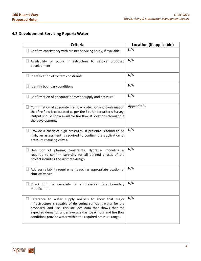
160 Hearst Way Proposed Hotel
4
CP-16-0372 Site Servicing & Stormwater Management Report
4.2 Development Servicing Report: Water
Criteria Location (if applicable)
Confirm consistency with Master Servicing Study, if available N/A
Availability of public infrastructure to service proposed development
N/A
Identification of system constraints N/A
Identify boundary conditions N/A
Confirmation of adequate domestic supply and pressure N/A
Confirmation of adequate fire flow protection and confirmation that fire flow is calculated as per the Fire Underwriter’s Survey. Output should show available fire flow at locations throughout the development.
Appendix ‘B’
Provide a check of high pressures. If pressure is found to be high, an assessment is required to confirm the application of pressure reducing valves.
N/A
Definition of phasing constraints. Hydraulic modeling is required to confirm servicing for all defined phases of the project including the ultimate design
N/A
Address reliability requirements such as appropriate location of shut-off valves
N/A
Check on the necessity of a pressure zone boundary modification.
N/A
Reference to water supply analysis to show that major infrastructure is capable of delivering sufficient water for the proposed land use. This includes data that shows that the expected demands under average day, peak hour and fire flow conditions provide water within the required pressure range
N/A

160 Hearst Way Proposed Hotel
5
CP-16-0372 Site Servicing & Stormwater Management Report
Description of the proposed water distribution network, including locations of proposed connections to the existing system, provisions for necessary looping, and appurtenances (valves, pressure reducing valves, valve chambers, and fire hydrants) including special metering provisions.
N/A
Description of off-site required feedermains, booster pumping stations, and other water infrastructure that will be ultimately required to service proposed development, including financing, interim facilities, and timing of implementation.
N/A
Confirmation that water demands are calculated based on the City of Ottawa Design Guidelines.
Appendix ‘B’
Provision of a model schematic showing the boundary conditions locations, streets, parcels, and building locations for reference.
N/A
4.3 Development Servicing Report: Wastewater
Criteria Location (if applicable)
Summary of proposed design criteria (Note: Wet-weather flow criteria should not deviate from the City of Ottawa Sewer Design Guidelines. Monitored flow data from relatively new infrastructure cannot be used to justify capacity requirements for proposed infrastructure).
N/A
Confirm consistency with Master Servicing Study and/or justifications for deviations.
N/A
Consideration of local conditions that may contribute to extraneous flows that are higher than the recommended flows in the guidelines. This includes groundwater and soil conditions, and age and condition of sewers.
N/A
Description of existing sanitary sewer available for discharge of wastewater from proposed development.
5.2 Sanitary Servicing
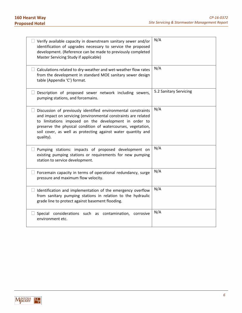
160 Hearst Way Proposed Hotel
6
CP-16-0372 Site Servicing & Stormwater Management Report
Verify available capacity in downstream sanitary sewer and/or identification of upgrades necessary to service the proposed development. (Reference can be made to previously completed Master Servicing Study if applicable)
N/A
Calculations related to dry-weather and wet-weather flow rates from the development in standard MOE sanitary sewer design table (Appendix ‘C’) format.
N/A
Description of proposed sewer network including sewers, pumping stations, and forcemains.
5.2 Sanitary Servicing
Discussion of previously identified environmental constraints and impact on servicing (environmental constraints are related to limitations imposed on the development in order to preserve the physical condition of watercourses, vegetation, soil cover, as well as protecting against water quantity and quality).
N/A
Pumping stations: impacts of proposed development on existing pumping stations or requirements for new pumping station to service development.
N/A
Forcemain capacity in terms of operational redundancy, surge pressure and maximum flow velocity.
N/A
Identification and implementation of the emergency overflow from sanitary pumping stations in relation to the hydraulic grade line to protect against basement flooding.
N/A
Special considerations such as contamination, corrosive environment etc.
N/A

160 Hearst Way Proposed Hotel
7
CP-16-0372 Site Servicing & Stormwater Management Report
4.4 Development Servicing Report: Stormwater Checklist
Criteria Location (if applicable)
Description of drainage outlets and downstream constraints including legality of outlets (i.e. municipal drain, right-of-way, watercourse, or private property)
6.0 Stormwater Management
Analysis of available capacity in existing public infrastructure. N/A
A drawing showing the subject lands, its surroundings, the receiving watercourse, existing drainage patterns, and proposed drainage pattern.
Pre- and Post-Development Plans
Water quantity control objective (e.g. controlling post-development peak flows to pre-development level for storm events ranging from the 2 or 5 year event (dependent on the receiving sewer design) to 100 year return period); if other objectives are being applied, a rationale must be included with reference to hydrologic analyses of the potentially affected subwatersheds, taking into account long-term cumulative effects.
6.0 Stormwater Management
Water Quality control objective (basic, normal or enhanced level of protection based on the sensitivities of the receiving watercourse) and storage requirements.
6.0 Stormwater Management
Description of the stormwater management concept with facility locations and descriptions with references and supporting information.
6.0 Stormwater Management
Set-back from private sewage disposal systems. N/A
Watercourse and hazard lands setbacks. N/A
Record of pre-consultation with the Ontario Ministry of Environment and the Conservation Authority that has jurisdiction on the affected watershed.
N/A
Confirm consistency with sub-watershed and Master Servicing Study, if applicable study exists.
N/A
Storage requirements (complete with calculations) and Appendix ‘F’

160 Hearst Way Proposed Hotel
8
CP-16-0372 Site Servicing & Stormwater Management Report
conveyance capacity for minor events (1:5 year return period) and major events (1:100 year return period).
Identification of watercourses within the proposed development and how watercourses will be protected, or, if necessary, altered by the proposed development with applicable approvals.
Sediment and Erosion Control Plan
Calculate pre and post development peak flow rates including a description of existing site conditions and proposed impervious areas and drainage catchments in comparison to existing conditions.
6.0 Stormwater Management, Appendix ‘F’
Any proposed diversion of drainage catchment areas from one outlet to another.
6.0 Stormwater Management
Proposed minor and major systems including locations and sizes of stormwater trunk sewers, and stormwater management facilities.
6.0 Stormwater Management
If quantity control is not proposed, demonstration that downstream system has adequate capacity for the post-development flows up to and including the 100 year return period storm event.
Appendix ‘A’
Identification of potential impacts to receiving watercourses N/A
Identification of municipal drains and related approval requirements.
N/A
Descriptions of how the conveyance and storage capacity will be achieved for the development.
6.0 Stormwater Management
100 year flood levels and major flow routing to protect proposed development from flooding for establishing minimum building elevations (MBE) and overall grading.
Lot Grading, Drainage Plan & sediment Control Plan
Inclusion of hydraulic analysis including hydraulic grade line elevations.
N/A

160 Hearst Way Proposed Hotel
9
CP-16-0372 Site Servicing & Stormwater Management Report
Description of approach to erosion and sediment control during construction for the protection of receiving watercourse or drainage corridors.
7.0 Sediment and Erosion Control
Identification of floodplains – proponent to obtain relevant floodplain information from the appropriate Conservation Authority. The proponent may be required to delineate floodplain elevations to the satisfaction of the Conservation Authority if such information is not available or if information does not match current conditions.
N/A
Identification of fill constraints related to floodplain and geotechnical investigation.
N/A
4.5 Approval and Permit Requirements: Checklist
The Servicing Study shall provide a list of applicable permits and regulatory approvals necessary for the
proposed development as well as the relevant issues affecting each approval. The approval and permitting
shall include but not be limited to the following:
Criteria Location (if applicable)
Conservation Authority as the designated approval agency for modification of floodplain, potential impact on fish habitat, proposed works in or adjacent to a watercourse, cut/fill permits and Approval under Lakes and Rivers Improvement Act. The Conservation Authority is not the approval authority for the Lakes and Rivers Improvement Act. Where there are Conservation Authority regulations in place, approval under the Lakes and Rivers Improvement Act is not required, except in cases of dams as defined in the Act.
N/A
Application for Certificate of Approval (CofA) under the Ontario Water Resources Act.
N/A
Changes to Municipal Drains. N/A
Other permits (National Capital Commission, Parks Canada, Public Works and Government Services Canada, Ministry of Transportation etc.)
N/A

160 Hearst Way Proposed Hotel
10
CP-16-0372 Site Servicing & Stormwater Management Report
4.6 Conclusion Checklist
Criteria Location (if applicable)
Clearly stated conclusions and recommendations 8.0 Summary
9.0 Recommendations
Comments received from review agencies including the City of Ottawa and information on how the comments were addressed. Final sign-off from the responsible reviewing agency.
All are stamped
All draft and final reports shall be signed and stamped by a professional Engineer registered in Ontario
All are stamped