proposed implementat on of mandatory water effic ency labell ng
TRANSCRIPT
Development of CMU Direct-Drive Arm II
Takeo Kanade Donald Schmitz
Robotics Institute Carnegie-Mellon University
Pittsburgh, Pa. 15213
March 1, 1985
Copyright @ 1985 The Vision Laboratory, Robotics Institute, CMU
This research was partly supported by a Ben Franklin Challenge Grant administered by Western Pennsylvania Advanced Technology Center, and partly by AT&T Bell Laboratories Special Purpose Grants Program.
i
Table of Contents
1 Introduction 2 Design Issues
2.1 Summary of DD Arm I 2.2 Design Specifications for DD Arm II
3 Mechanical Design 4 Servo System Design
4.1 Torque Motors 4.2 Amplifiers 4.3 Shaft Encoders
5.1 Coordinating Processor 5.2 Joint Processors 5.3 Floating Point Processor
5 Real-time Arm Controller Design
6 Summary Acknowledgments References
2 2 2 3 4 6 7 8 8
10 11 12 13 13 16 17

ii
List of Figures Figure 1 : Configuration of DD I1 Figure 2: Photograph of DD II Figure 3: Assembly Drawing of Joint 5. Figure 4: Photograph of Joint 4 Assembly Figure 5: Photograph of Pan Cake 2-Speed Resolvers Figure 6: Computed Torque Robot Arm Control Algorithm Figure 7: Configuration of DD II Control Hardware
5 6 7 9
10 11 12
iii
List of Tables
Table 1 : Motor Specifications for DD I and DD II Table 2: CMU DD Arm II Specifications as Compared with DD Arm I
14 15
1
Abstract
The CMU Direct Drive Arm II (DD II) is the second direct-drive arm designed and constructed at the
Robotics Institute, Carnegie Mellon University. It is an electric 6 degree-of-freedom robot, in which all
of the joints are of direct drive construction. Featuring high performance Samarium Cobalt magnet
brushless DC motors and light weight.aluminum construction, the robot has been designed to have a
minimum payload of 2.5 Kg with a maximum transit time of 1 second (corresponding to tip speeds of
4 mlsec). High resolution pancake resolvers are mounted directly to the joint shafts for very accurate
feedback. Static accuracy is 20.1 mm. Taking advantage of the dynamic simplicity inherent in direct
drive design, the controller is capable of dynamic force compensation in real-time. Such a controller
can accurately follow a trajectory at very high speeds. In this paper we discuss the design of this new
arm, particularly our solutions to the difficulties of practical implementation of direct drive.
2
1 Introduction
The direct drive concept of robot arm design is that by eliminating transmission mechanisms
between the arm motors and the arm itself, less noise in the form of friction, gear loss, and backlash is
introduced into the arm motion. This results in an easily identified dynamic model of the arm,
simplifying the design of, and reducing the computation power necessary to implement sophisticated
model based control schemes. Such control schemes are necessary for making full use of the
mechanical capabilities of an arm designed for high speeds and very accurate posltioning, and are
also required for many types of assembly operations.
The direct drive design also allows for a very elegant mechanical construction. All of the joints in
such an arm are essentially identical, allowing for common components in joint assemblies. Since the
motors and pancake resolvers for each joint are mounted on one common shaft, a single bearing
assembly is used. Thus a direct drive joint generally has fewer and more easily manufactured
components, making it attractive for commercial applications.
The concept of direct drive robots was developed at CMU, and the first prototype direct drive robot,
CMU DD Arm I, was built late in 1981 by Asada and Kanade[l]. This robot demonstrated the
improvement in robot performance possible with direct drive. However it also made shortcomings
clear, both in its design and in the technology available for building such an arm. In developing DD
Arm 11, the goal is to develop reliable, practical hardware using state of the art components in order to
conduct extensive research into the capabilities and application of direct drive robots. At present,
final integration of this system is ongoing, with completion expected in late 1984. This paper presents
the design of the arm and controller.
2 Design Issues
2.1 Summary of DD Arm I
Before presenting the design of the DD Arm 11, let us summarize the first direct-drive arm (CMU DD
Arm I ) . The CMU DD Arm I was a 6 degree of freedom, rotary joint robot. The robot was designed to
be suspended from an overhead structure, providing a hemispherical workspace with a 1 meter
radius. Payload was specified as 5 Kg, and maximum tip speed as 4 meterslsec.
The arm was built making extensive use of machined aluminum castings. The resultant structure
had a mass 250 Kg. Each joint was driven by one or a pair of pancake DC servomotors. The three
base motors were standard AlNiCo magnet motors, whereas the three tip joints, which are loads to the
3
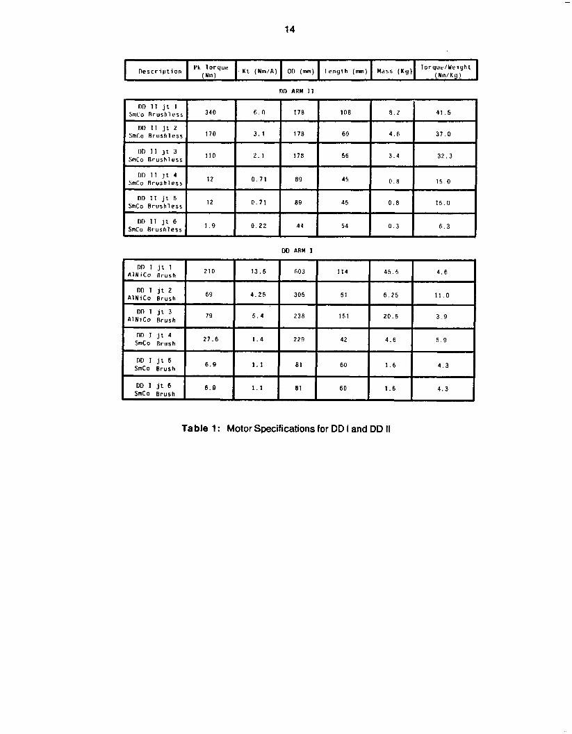
base joints, were more efficient SmCo magnet motors. [l] A summary of motor specifications can be
found in Table 1. Incremental optical shaft encoders were used at each joint to provide position
feed back.
A control scheme was implemented using six independent analog PID controllers. In addition, the
output of the PID controllers could be summed with another external signal provided by a PDP-11/23
microprocessor for implementing assorted feed forward control schemes. [2]
The major problems discovered in the system could be reduced to two major points:
0 The motors were not properly specified for the desired loads and speeds. This problem was aggravated by the extremely heavy construction.
0 The PDP-11/23 did not have enough computational power to implement sophisticated control schemes at real time update rates.
2.2 Design Specifications for DD Arm II
Based on our experience of constructing and controlling DD Arm I, we started the design of a
second direct-drive arm (CMU DD Arm II) in 1983. The CMU DD Arm II is primarily a research arm
intended for a wide range of high performance robot manipulation tasks. In order to correct the
problems encountered in CMU DD I, we established a set of minimal requirements necessary for
conducting proposed research. Following are our performance criteria.
0 Configuration: Direct drive joints are inefficient for generating large continuous torques, thus vertical motion for a direct drive robot should be at a minimum. Based on observation of commercial assembly robots, a configuration similar to the popular Japanese SCARA robot was chosen, with a 1 meter reach and 0.25 meter vertical travel. In addition, a three axis wrist was specified to yield a full 6 DOF with simple kinematics.
0 Speed: The arm must be capable of high speeds and accelerations to allow testing of control and sensing systems at extreme levels of performance, and to take advantage of the direct drive construction. We discarded typical maximum tip speed criteria, as it is not indicative of real world performance, and chose instead to specify a maximum transit time for each joint in any possible arm configuration. We chose this maximum time to be 1 second in the worst case; thus the arm can go from any point to any point in its work space in 1 second or less. If we consider the arm tip as it travels the maximum circumference of its work space, we see it should average 4.2 m/s, significantly faster than commercial robots, such as the 1 m/s rating of the IBM Series 1 robot.
0 Payload: The arm must be capable of carrying loads such as sensors, grippers, and small objects to allow instrumenting the arm or testing it in simulated real world conditions. Considering the mass of available sensors and grippers, a payload of 2.5 Kg at maximum speed was established. Using the payload and speed specifications, simple worst case torque requirements were calculated in order to specify the torque requirements for each joint. Although not specified, the arm is capable of carrying a payload several times larger than 2.5 Kg at a reduced speed.
4
0 Accuracy: Position feedback sensors should be of high resolution and accuracy, both for accurate control and for use in analyzing the performance of the arm and controller. Considering the 16 bit computers being used to implement the control algorithms, and existing shaft encoder technology, a resolution of 216 intervals per shaft rotation was chosen, and a typical accuracy of +1 LSB. This corresponds to 65536 divisions per angular rotation, each division being approximately 20 seconds of arc. Since the encoders must also be used to commutate the brushless motors being used, they should be absolute encoders.
0 Modularity: The arm should be easily reconfigured and modified. No major assembly of the arm should depend on the construction of any other. Whenever possible the arm will be of modular design, so that the location or orientation of a joint can be changed with minimal modification of parts.
0 Reliability and Repeatability: The arm and related hardware should be reliable and repeatable. This has been defined as capable of continuous operation at the maximum specified payload, speed, and accuracy with no degradation in performance over time aside from normal wear of the components.
3 Mechanical Design
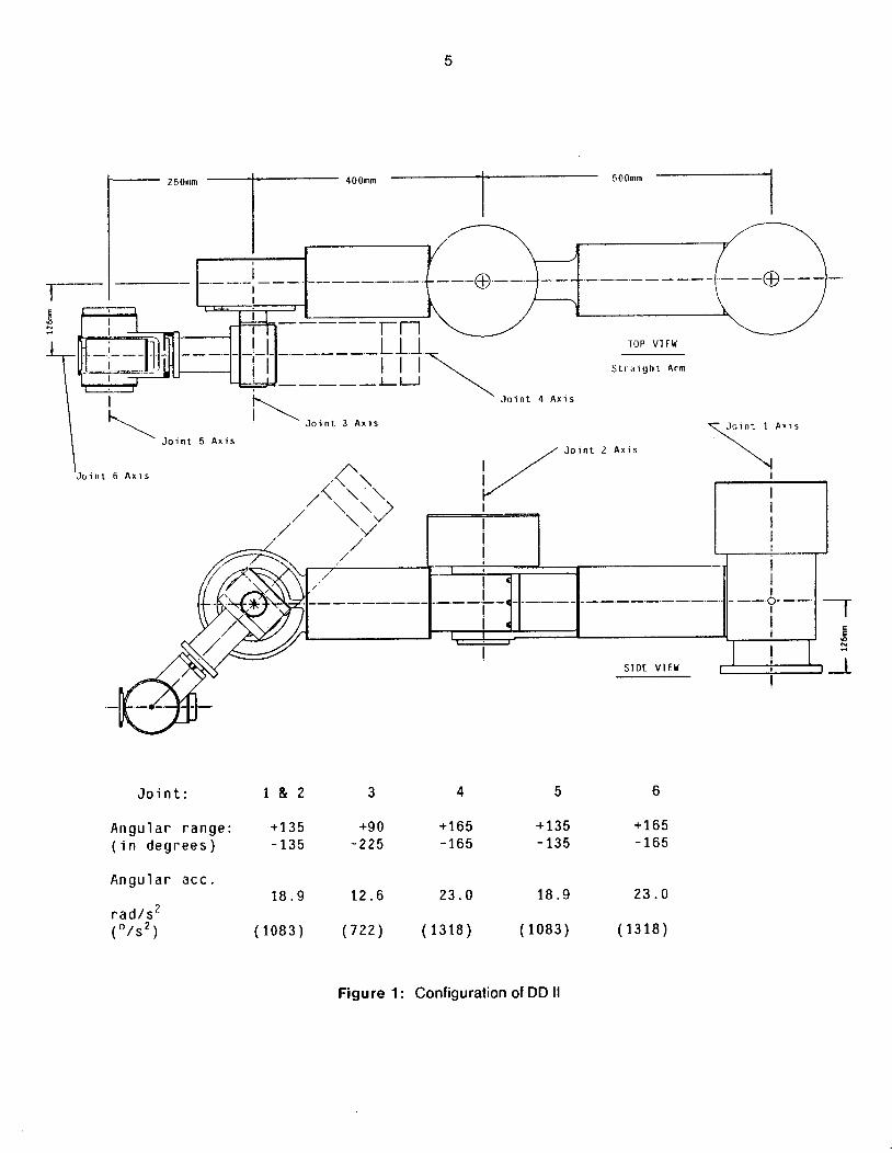
The final configuration for DD II is shown in Figure 1 and in the photograph of Figure 2. This
configuration allows the arm to cover a very large horizontal area, essentially a "donut" of outer
radius 900 mm and inner radius 217 mm with a wedge shaped cutout, yielding approximately 1.8 m2 of
work area. Over this area a maximum vertical motion of 250 mm is possible; certain tasks may allow
joint 3 to wrap around, doubling the vertical range.
Structural design of the arm is similar to that of aircraft gimbal systems. Each joint has one fairly
complex, accurately machined aluminum housing. This housing controls the geometrical
relationships of the bearing assembly, of the servo components to the bearing assembly, and of the
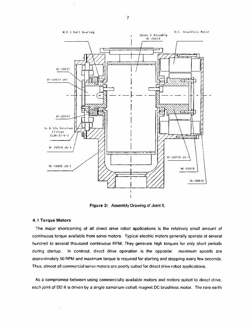
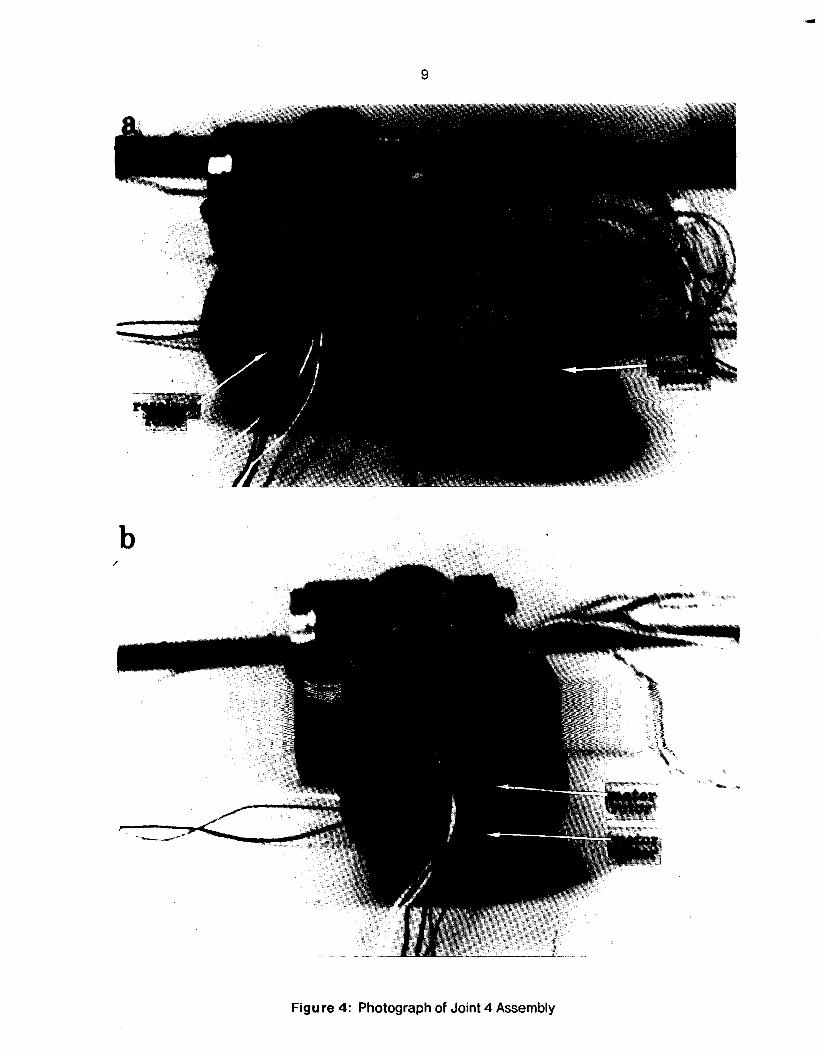
rotational axes of consecutive joints. Figure 3 and Figure 4 give some detail of the construction of a
typical joint: Figure 3 shows a cutaway view of joint 5, and Figure 4 (a) and (b) are the photos of joint 4
assembly.
Structural elements, of which joint shafts are a subset, are large diameter thin-walled aluminum
cylinders, yielding maximum stiffness from minimal material. This construction has resulted in a
structure having a mass of only 35 Kg (including motors). The large diameter motor shafts
necessitated the use of thin section bearings in the joint assemblies. These bearings are built in large
diameters, but with relatively small balls, greatly reducing their friction, weight, and size compared to
more conventional bearings of this bore diameter. The bearings are mechanically preloaded to
eliminate play in the joint for up to the specified loads.
5
1
J o i n t 1 A x i s
\
J o i n t :
A n g u l a r r a n g e : ( i n d e g r e e s )
A n g u l a r a c c .
r a d / s 2 ( O / S 2 )
1 & 2
+135 -135
18.9
(1083)
3 4
+90 +165 -225 -165
12.6 23.0
(722) (1328)
5 6
+135 +165 - 135 -165
18.9 23.0
(1083) (1318)
Figure 1 : Configuration of DD II
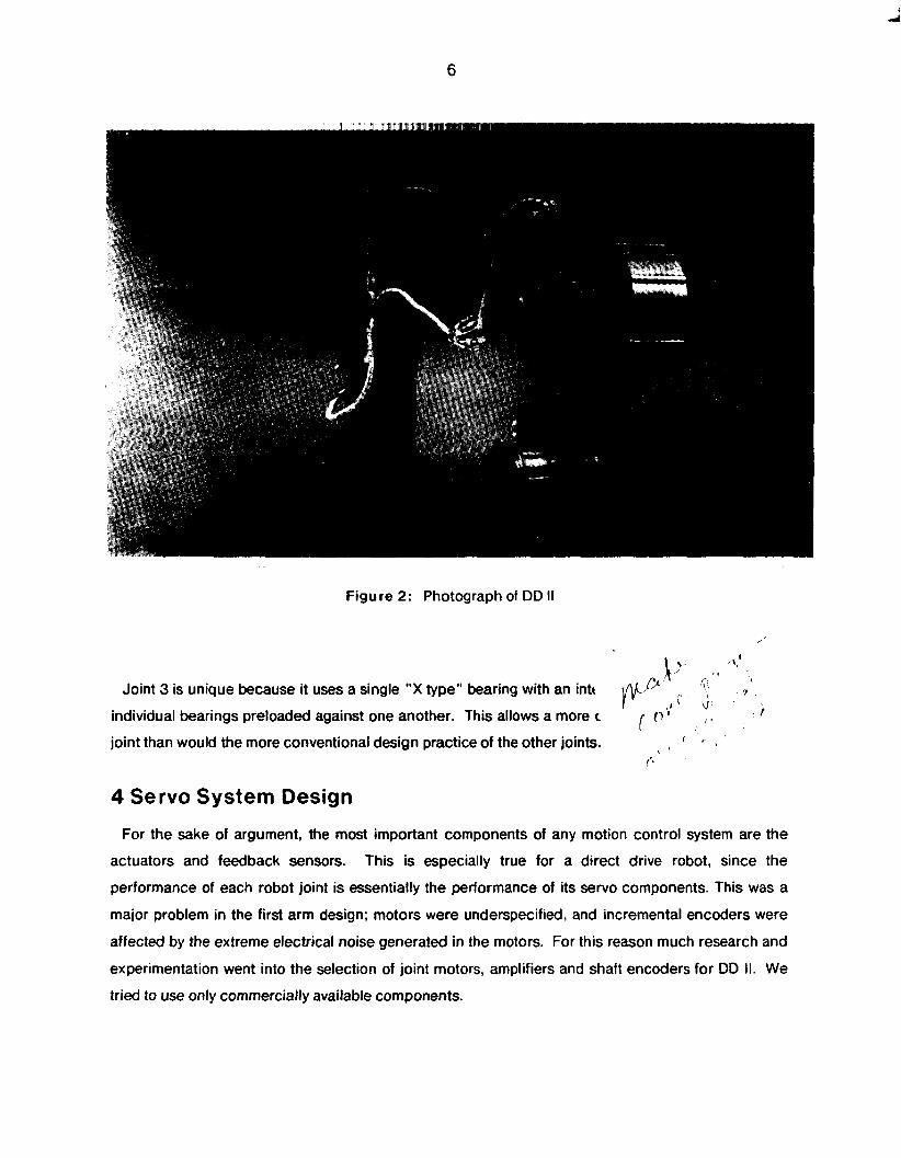
Figure 2: Photograph of DD II
p , I , 7' ' q
7
individual bearings preloaded against one another. This allows a more c rycD of r ;; I
Joint 3 is unique because it uses a single "X type" bearing with an intt
joint than would the more conventional design practice of the other joints. , ' . i I
I"
6
4 Servo System Design
For the sake of argument, the most important components of any motion control system are the
actuators and feedback sensors. This is especially true for a direct drive robot, since the
performance of each robot joint is essentially the performance of its servo components. This was a
major problem in the first arm design; motors were underspecified, and incremental encoders were
affected by the extreme electrical noise generated in the motors. For this reason much research and
experimentation went into the selection of joint motors, amplifiers and shaft encoders for DD 11. We
tried to use only commercially available components.
7
M . P . 3 R a l l R r a r i n g
7
i V I - 2 0 0 1 4 c h - 1
D . C . R r u : , h l e s s M u t o r I J o i n t R As,einlily
I
I
I
Figure 3: Assembly Drawing of Joint 5.
4.1 Torque Motors
The major shortcoming of all direct drive robot applications is the relatively small amount of
continuous torque available from servo.motors. Typical electric motors generally operate at several
hundred to several thousand continuous RPM. They generate high torques for only short periods
during startup. maximum speeds are
approximately 50 RPM and maximum torque is required for starting and stopping every few seconds.
Thus, almost all commercial servo motors are poorly suited for direct drive robot applications.
In contrast, direct drive operation is the opposite:
As a compromise between using commercially available motors and motors suited to direct drive,
each joint of DD II is driven by a single samarium-cobalt magnet DC brushless motor. The rare earth
a
SmCo magnets have a high magnetic field strength to weight ratio, compared to more common
AlNiCo or ceramic magnets, resulting in a high torque to weight ratio. Brushless DC motors, while
requiring more sophisticated drive electronics, are better suited for direct drive applications than
more conventional brush motors. They make use of an inside out construction, with fixed windings
mechanically mounted to the motor housing for good heat dissipation. This motor design can be seen
in the photograph of joint 4 shown in Figure 4. This allows brushless motors to produce more
continuous torque, particularly at low speeds, than brush type motors. They are also more reliable
than conventional motors, as they have no brushes to wear out.
4.2 Amplifiers
The motors are driven by three channel PWM amplifiers with current feedback, which generate sine
wave commutation currents based on the angular position of the motor shaft. The amplifiers are
industrial equipment motor controllers, capable of delivering 50 A: each amplifier has been calibrated
for each motor to produce peak motor torque at the 10 V,, maximum input. The brushless DC torque
motor operation is similar to that of a synchronous AC motor with a constant phase angle between
rotor and stator magnetic fields. The result of electronically commutating the motor is a linear torque
versus current amplitude relationship, without the characteristic torque ripple associated witk brush
commutation.
4.3 Shaft Encoders
Angular position feedback for each joint is obtained from a 1-32 speed pancake resolver mounted
coaxialy with the joint shaft. The resolvers are essentially rotary transformers; excited with a 26 Vrms,
400 Hz ac signal, they generate four output signals which are proportional to the sine and cosine of
the shaft angle (between the resolver rotor and stator), and the sine and cosine of 32 times the shaft
angle (32 being the speed ratio of the resolver). The photograph in Figure 5 shows the resolver of
joint 4 prior to final assembly.
The relationship between the resolver output signals and the shaft angle is very accurate, allowing
the signals to be processed to generate a 16 bit binary angle. The accuracy of the system is based on
both the accuracy of the R I D converters and the mechanical accuracy of the resolvers which are
rated at +15 seconds of arc and 220 seconds of arc respectively, yielding a worst case error of +2
LSB of the 16 bit binary angle.
9
b /
Figure 4: Photograph of Joint 4 Assembly
10
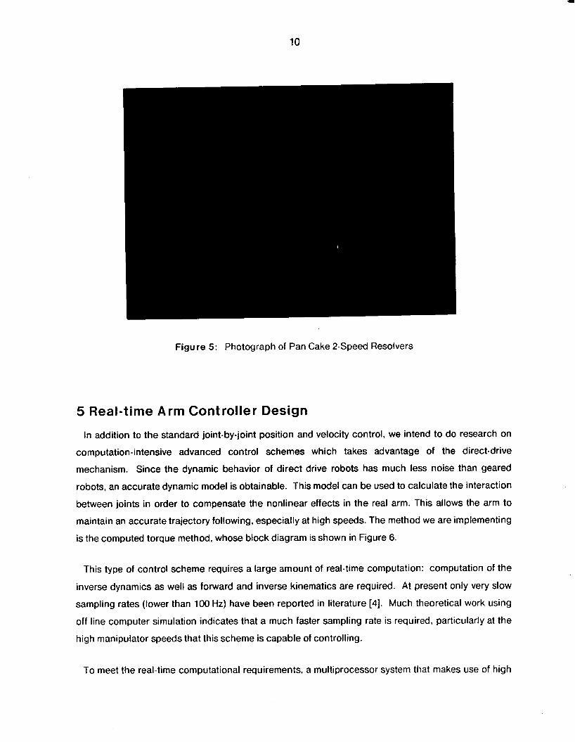
Figure 5: Photograph of Pan Cake 2-Speed Resolvers
5 Real-time Arm Controller Design
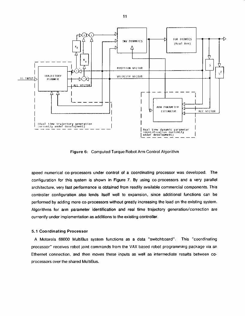
In addition to the standard joint-by-joint position and velocity control, we intend to do research on
computation-intensive advanced control schemes which takes advantage of the direct-drive
mechanism. Since the dynamic behavior of direct drive robots has much less noise than geared
robots, an accurate dynamic model is obtainable. This model can be used to calculate the interaction
between joints in order to compensate the nonlinear effects in the real arm. This allows the arm to
maintain an accurate trajectory following, especially at high speeds. The method we are implementing
is the computed torque method, whose block diagram is shown in Figure 6.
This type of control scheme requires a large amount of real-time computation: computation of the
inverse dynamics as well as forward and inverse kinematics are required. At present only very slow
sampling rates (lower than 100 Hz) have been reported in literature [4]. Much theoretical work using
off line computer simulation indicates that a much faster sampling rate is required, particularly at the
high manipulator speeds that this scheme is capable of controlling.
To meet the real-time computational requirements, a multiprocessor system that makes use of high
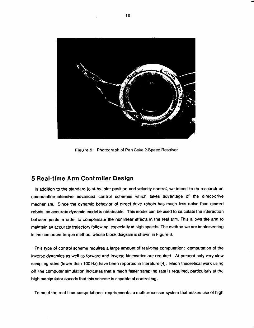
Figure 5: Photograph of Pan Cake 2-Speed Resolver
10
5 Real-time Arm Controller Design
In addition to the standard joint-by-joint position and velocity control, we intend to do research on
computation-intensive advanced control schemes which takes advantage of the direct-drive
mechanism. Since the dynamic behavior of direct drive robots has much less noise than geared
robots, an accurate dynamic model is obtainable. This model can be used to calculate the interaction
between joints in order to compensate the nonlinear effects in the real arm. This allows the arm to
maintain an accurate trajectory following, especially at high speeds. The method we are implementing
is the computed torque method, whose block diagram is shown in Figure 6.
This type of control scheme requires a large amount of real-time computation: computation of the
inverse dynamics as well as forward and inverse kinematics are required. At present only very slow
sampling rates (lower than 100 Hz) have been reported in literature [4]. Much theoretical work using
off line computer simulation indicates that a much faster sampling rate is required, particularly at the
high manipulator speeds that this scheme is capable of controlling.
To meet the real-time computational requirements, a multiprocessor system that makes use of high
11
C b
~
A FOR TIYAMICS - - a
TNV D Y N M A l C S * - -
( R e a l A r m )
Figure 6: Computed Torque Robot Arm Control Algorithm
K P
_ - - - - - - K "
I I
I
I
P O S l l l O N VFCTOR
T R A J I L T O R Y V F I O C i T Y V F L T O R 1;) I N P l J l pi ANNFR
I ALC V f L T O R
A n - - ---- -- - - --
I I r I I > I I - - - - - -. - -
speed numerical co-processors under control of a coordinating processor was developed. The
configuration for this system is shown in Figure 7. By using co-processors and a very parallel
architecture, very fast performance is obtained from readily available commercial components. This
controller configuration also lends itself well to expansion, since additional functions can be
performed by adding more co-processors without greatly increasing the load on the existing system.
Algorithms for arm parameter identification and real time trajectory generation/correction are
currently under implementation as additions to the existing controller.
2 5
0 -
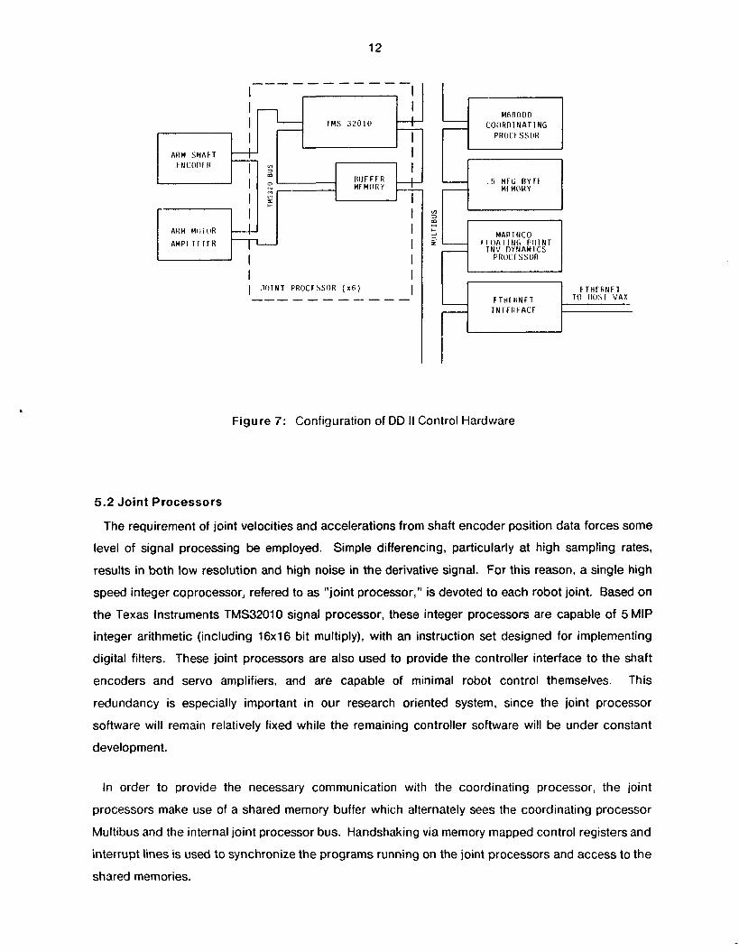
5.1 Coordinating Processor
A Motorola 68000 MultiBus system functions as a data "switchboard". This "coordinating
processor" receives robot joint commands from the VAX based robot programming package via an
Ethernet connection, and then moves these inputs as well as intermediate results between co-
processors over the shared MultiBus.
ARM P A R A M F l F R I I b I I
I F S l l M A T O R I ALC VFCTOR
I

12
8
Mfi A 0 0 0 CO(lRn I N A T 1 NG
PROCC SSOR
L F T H r R N F T 0 H O S i VAX
Figure 7: Configuration of DD II Control Hardware
5.2 Joint Processors
The requirement of joint velocities and accelerations from shaft encoder position data forces some
level of signal processing be employed. Simple differencing, particularly at high sampling rates,
results in both low resolution and high noise in the derivative signal. For this reason, a single high
speed integer coprocessor, refered to as "joint processor," is devoted to each robot joint. Based on
the Texas Instruments TMS32010 signal processor, these integer processors are capable of 5 MIP
integer arithmetic (including 16x1 6 bit multiply), with an instruction set designed for implementing
digital filters. These joint processors are also used to provide the controller interface to the shaft
encoders and servo amplifiers, and are capable of minimal robot control themselves. This
redundancy is especially important in our research oriented system, since the joint processor
software will remain relatively fixed while the remaining controller software will be under constant
development.
In order to provide the necessary communication with the coordinating processor, the joint
processors make use of a shared memory buffer which alternately sees the coordinating processor
Multibus and the internal joint processor bus. Handshaking via memory mapped control registers and
interrupt lines is used to synchronize the programs running on the joint processors and access to the
shared memories.
13
5.3 Floating Point Processor
In addition to making efficient use of the hardware with the coprocessor architecture, techniques
were developed for optimizing the Newton-Euler inverse dynamics algorithm for the specific case of
DD II. This reduced the number of operations necessary for calculating an inverse dynamics solution
to slightly less than 500 floating point additions ar,d multiplications [3]. Using this optimized
algorithm, we can perform this calculation in 1.2 msec with a commercially available Marinco floating
point coprocessor capable of approximately 0.5 MFLOP, rather than a much more costly array
processor.
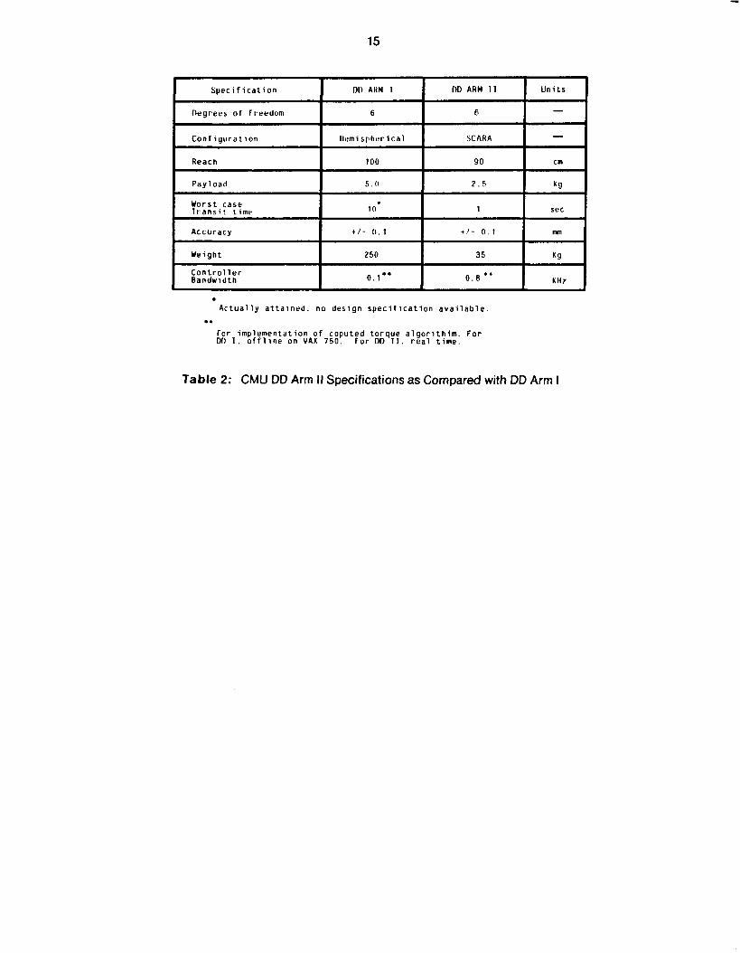
6 Summary
As the system described demonstrates, a high-performance 6-dof direct-drive robot has been
developed using existing technology. Computer simulation of the arm with proposed controllers has
produced very good results, and extensive experiments are planned to verify current theoretical work.
Table 2 outlines the expected performance of the system, and shows the improvement over the DD
Arm I.
Currently, further design modifications are under consideration to take advantage of information
gathered in the design of DD Arm II, as well as recent advances in torque motor technology. Plans
include integrating the arm with a Lisp-based robot programming language developed at CMU, and
experimenting with new ultra high torque motors using Neodymium permanent magnets.
14
DD ARM 11
SmCo R r u s h l e s s
DD ARM J
Table 1 : Motor Specifications for DD I and DD II
15
A c t u a l l y a t t a i n e d . no d e s i g n s p e c i f i c a t i o n a v a i l a b l e
f o r i m p l e m e n t a t i o n o f coputed t o r q u e a l g o r i t h i m . F o r DD I . o f f l i n e on VAX 7 5 0 . For DD 11. r e a l t i m e .
..
Table 2: CMU DD Arm I1 Specifications as Compared with OD Arm I
16
Acknowledgments
We thank for many people who have contributed to the development of CMU Direct-Drive Arm II:
Danny Ratner (visiting from RAFAEL, Israel) for his contribution to the mechanical design of the DD
Arm 11, Regis Hoffman for his programming support, Nobu Tanaka (visiting from Kubota, Ltd., Japan)
for his effort in programming the joint processors, Robert Spies for his electronics design of the joint
processors, and Mark DeLouis for his excellent technical work in constructing the arm.
17
References
[l] Haruhiko Asada and Takeo Kanade. Design of Direct-Drive Mechanical Arms. Robotics Institute Technical Report, Carnegie-Mellon University, 1981.
Haruhiko Asada, Takeo Kanade and lchiro Takeyama. Control of a Direct-Drive Arm. Robotics Institute Technical Report, Carnegie-Mellon University, 1982.
Takeo Kanade, Pradheep Khosla and Nobuhiko Tanaka. Real-Time Control of CMU Direct-Drive Arm II Using Customized Inverse Dynamics. In 23rd /E€€ Conference on Decision and Control. December, 1984.
[2]
[3]
[4] Luh J. Y. S., Walker, M. W. and Paul R. P. Resolved.Acceleration Control of Mechanical Manipulators. / € € E Transacfions on Automatic Control 25(3):468-474, June, 1980.