propulsion lab manual · 2018-09-11 · in this experiment, we measure the calorific value of solid...
TRANSCRIPT

PROPULSION LAB
MANUAL
Measurement of Calorific Value of a
Solid Fuel Sample using a Bomb
Calorimeter
DEPARTMENT OF AEROSPACE ENGINEERING
Indian Institute of Technology
Kharagpur
CONTENTS
1. Introduction
2. Background and theory
3. IKA C 200 calorimetric measurements basics
4. Calorimeter and its components
5. Procedures
6. Results
7. References
1. INTRODUCTION
Abstract
In this experiment, we measure the calorific value of solid fuel by using a bomb
calorimeter. We burn benzoic acid to find out the heat capacity of the equipment, this is
called calibration of the system. After the calibration we put that calibrated value to the
system as a reference for the further calculation of the fuel. We burn a small amount of
solid fuel in isoperibol mode (17 minutes testing time) or dynamic mode (8 minutes). We
get the result in any one mode and finally we can compare the experimental value with the
theoretical heating value of the given fuel.
Introduction
In this experiment we will be using a bomb calorimeter. A bomb calorimeter measures
the heat of combustion during a reaction. This will allow us to measure the calorific
value of the solid fuel. We will first find out the heat capacity of the calorimeter using
benzoic acid which will be fully combusts in oxygen. The bomb calorimeter is a closed
system, therefore there is no heat transfer with the surroundings and we will be able to

use the First Law of Thermodynamics: conservation of energy, to find out the necessary
values. (Traum, 2009)
2. BACKGROUND AND THEORY
Bomb calorimetry is a process which can be used to determine the heat of combustion or
calorific value of a solid or a liquid material. The Bomb Calorimeter was invented by a great
chemist in the 18th century named Marcellin Berthelot. The sample is compressed with the
oxygen inside a sample container or sample crucible within the bomb calorimeter. The
bomb calorimeter is ignited with the help of nichrome wire which produces heat while
supplying current and finally the heat produced by the wire will be transferred to the
samples through the burning cotton thread. The burning sample generates heat and
increase the temperature of the bomb which is inside the water jacket. The increase of
temperature is measured by the thermometer or temperature sensor and ultimately finds
the temperature difference of the water for the calculation. In figure 1 we can see that the
system is a closed system there is no heat exchange between the surroundings and
calorimeter, making it an adiabatic system. A water stirrer is used for the evenly
distribution of heat in the water jacket of the calorimeter.
Figure: 1. Bomb calorimeter conceptual drawing [2].
Since volume does not change, a bomb calorimeter measures the heat evolved under
constant volume, qv,
qv = C * dT, where dT is the temperature increase.
The qv so measured is also called the change in internal energy, dU.
Note that dU = qv = C * dT

The enthalpy (H), which in the present case is enthalpy of combustion, is defined as:
H = U + PV
and correspondingly a change in H (denoted by delta H) is given by:
dH = dU + (d(P V))
= dU + dn R T (applying the ideal gas law)
From the above expression, we see that delta U and delta H would be identical only if the
pressure in the bomb remains constant. If the amount of gases in the bomb remain
constant, delta P would be zero and thus delta U = delta H. However, in most combustion
reactions the molar amounts of gases change and therefore a method for calculating the
delta (PV) term is required.
where R is the gas constant (8.31 J mol−1 K−1). The term denoted by “small” can be
neglected when changes in temperature are small (couple of 0C). Note that delta n can be
either positive (the amount of gaseous components increase) or negative (the amount of
gaseous components decrease). Also the contribution of liquids and solids to the delta PV
term is negligible.
Example 1:
When 0.1025 g of benzoic acid was burnt in a bomb calorimeter the
temperature of the calorimeter increased by 2.165° C. For benzoic
acid dH°comb = -3227 kJ mol-1. Calculate the heat capacity of the
calorimeter.
Solution: The equation for the combustion is,
C7H6O2(s) + 7.5 O2(g) -> 7CO2(g) + 3H2O(l), dH° = 3227 kJ
Since 7.5 moles of O2 gas is needed, and 7 moles of CO2 is produced, some
pressure-volume work is done, to the calorimeter:
P V = dn R T, where dn = (7 - 7.5) = - 0.5 mol
dU = dH - dn R T
= - 3227 - (-0.5*8.314298*298)
= - 3226 kJ/mol (a small correction)
The amount of heat produced by 0.1025 g benzoic acid is
q = 0.1025/122.13 mol x 3226 (kJ/mol) = 2.680 kJ
Thus, the heat capacity is
C = q / dT = 2.680 / 2.165 = 1.238 kJ / K.
After the heat capacity is determined, the calorimeter is ready to be used to measure
the enthalpy of combustion of other substances.

Example 2:
A table of thermodynamic data gives dHf = -285.8 kJ/mol for water. A bomb
calorimeter measurement gives the heat of combustion for H2 as -282.0 kJ/mol.
Estimate the error of the enthalpy measurement.
Solution Reinterpret the problem, we have
H2(g) + 0.5 O2(g) = H2O(l), dU = 282.0 kJ/mol.
Furthermore,
dn = -1.5
dH = dE + dn R T,
= - 282.0 + (-1.5 mol * 8.314 J/(mol K) * 298 K)
= (-282.0 - 3.72) kJ
= -285.7 kJ
The error is (285.8-285.7)/285.8 = 0.03%

3. IKA C200 CALORIMETRIC MESUREMENTS BASICS
Calculation
Combustion is carried out in a calorimeter under specific conditions. The decomposition
vessel (bomb) is filled with a weighed fuel sample, the fuel sample is ignited and the
temperature increase in the calorimeter system is measured. The specific calorific value of
the sample is calculated as follows
HV = (C * dT - QExt1 - QExt2) / m {1}
Where,
m- Weight of fuel sample
C- Heat capacity (C-value) of calorimeter system
DT - Calculated temperature increase of water in inner vessel of measuring cell
QExt1- Correction value for the heat energy generated by the cotton thread as ignition aid
QExt2- Correction value for the heat energy from other burning aids
The relevant standards are based on the following assumptions:
a. The temperature of the fuel and its combustion products is 25 °C.
b. The water contained in the fuel before combustion and the water formed whilst
combusting the hydrogenous compounds of the fuel is in fluid form after
combustion.
c. The atmospheric nitrogen has not oxidised.
d. The gaseous products after combustion consist of oxygen, nitrogen, carbon dioxide
and sulphur dioxide.
e. Solid materials may form (e.g. ashes).
Calibration
The calorimeter system must be calibrated before accurate measurements are possible.
This is done by combusting tablets made of certified benzoic acid with a known calorific
value. The heat quantity required to raise the temperature of the calorimeter system by
one Kelvin is used to determine the heat capacity of the so called "C value" of the system.
For this calculation the equation1 is adapted:
C = (HV * m + QExt1 + QExt2) / dT {2}
This value is used for determining the calorific values. The heat capacity is determined by
the measuring cell and the decomposition vessel (bomb). It has a significant influence on
the calorific value to be calculated and must be redetermined in particular when using for
the first time, after servicing and when parts are replaced. A monthly control measurement
is recommended.
Note: The system must be calibrated in every work mode used.
If a calorimeter is operated with several decomposition vessels, we will need to determine
the heat capacity of the system for each decomposition vessel. Ensure that calibration is
carried out under the same conditions as the subsequent tests. If substances are used in the
decomposition vessel in combustion tests (e.g. distilled water or solutions), we must use
exactly the same amount of this substance for calibration [3].
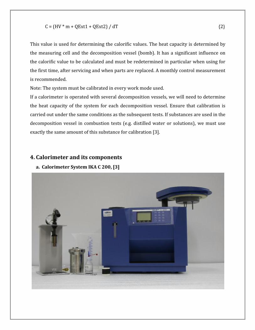
4. Calorimeter and its components
a. Calorimeter System IKA C 200, [3]

b. Calorimeter
d. Electrical connections
c. Water connections
e. Oxygen filling station
f. Decomposition vessel or bomb

5. PROCEDURES
1. Switch on the chiller unit and fix the temperature to 18 deg C.
2. Clean the calorimeter decomposition vessel (bomb), crucible, and other components.
3. Pour 5.0 ml of deionized water into the bomb to absorb the oxides of nitrogen formed
from nitrogen present in the oxygen mixture.
4. Take out the thread from the plastic packet by forceps and tie it with the ignition
wire.
5. Care must be taken to avoid overweight the sample, it must be realized that the peak
pressure developed during combustion is proportional to the size of the sample and
the initial oxygen pressure. Pellet size should be limited; not more than 1.1 g.
6. After keeping the fuel pellet in the pellet holder, make sure that the cotton thread is
touching the pellet and then close the bomb with the top cover by screwing the union
nut.
7. Hold the bomb carefully and keep it on the circle which is located on the oxygen
station base. Be sure that the oxygen nozzle is aligned with the bomb valve and then
rotate the top lever of the oxygen station in downward direction. Fill the bomb with
oxygen at 30 bars and keep it at this pressure atleast for one minute and then free the
bomb from the oxygen station.
8. Now switch on the IKA C200 bomb calorimeter: press ON (F1) to work with the
appliance and then the start screen will appear. If the system is going to start first
time, the system asks for 1st fill. Fill the outer tank with the chiller water and make
sure that the tank level is in between the min & max range of the water level which is
displayed on the left corner of the system. Then press F2 and go to prepare column.
9. Now go to weight column and put the weight of the sample, then come down to
calibration column: 0- for calculation, 1- for calibration, then come down to vessel
column: this is asking the name of the vessel (for single bomb- press 1), for QExt press
50 J/g (calorific value of cotton thread), and finally in the test no press date of the
experiment with the test serial no (like- 15122501= 25/12/15-01). After filling all,
place the bomb inside the calorimeter, close the upper cover and press OK. The
system starts and will be worked automatically [3].
10. The temperature rise is displayed on the screen and the result comes after
sometimes based on mode setting (dynamic or isoperibol). The modes timings are
such that, Dynamic modes takes 8 minutes and Isoperibol modes gives result in 17
minutes.
11. In order to ensure that the appliance works properly, we must set some parameters
if uses in the first time. Press F3 button before pressing OK in the serial no 9. Now go
to settings; it is displayed in this way: General, Calibration values, Unit, Language,
Operation, and Service.
General:
• Reference- (reference calorific value for benzoic acid- given to the benzoic acid
tablet strip = 26461 J/g)

• One way crucible- (without- for the case when sample burns under non
combustible crucible, with- for the case when sample burns with combustible
crucible)
• Date & time- (one time input)
• Operation- ( no of operation like- 1,2,3,.....)
Calibration values:
• Vessel 1-
• Vessel 2-
• Vessel 3-
• Vessel 4-
(Values which comes from calibration by benzoic acid)
Unit:
• Unit- J/g or Cal/g
Language:
• English
Operation:
• Isoperibol/Manual/Dynamic/Time control
Service:
• Ignition off- (To check whether ignition is working or not)
• Fill off- (To check whether water flows from outer tank to inner vessel or not)
• Empty off- (To check whether water flows from inner vessel to outside the
calorimeter or not)
• Stirrer off- (To check whether stirrer is working or not)
• Pump off- (To check whether pump is working or not: sound comes if working)
• Outer vessel off- (To check whether water flows from outer vessel to inner vessel
or not)
• Reset- (Reset all settings)
• Reinitiating- (If AD board does not work which is inside the top cover, then select
this option)
• Contrast- (This is for contrast setting of the screen, generally takes 50)
12. Results shows on the screen then open the top cover of the calorimeter, once the
cover opens water start draining from inner vessel to the chiller unit. After draining
of water, take out bomb from the calorimeter.
13. Write down the result in the record, then release the pressure of the bomb by using
pressure release tool and at the same time clean the bomb and other involved parts
carefully by a good quality tissue paper.
14. Switch off calorimeter, chiller unit, and finally close the top cover of the calorimeter.
It is advised to cover the calorimeter by a clean cloth to protect it from the dust
particles.

6. RESULTS Some results are shown here for dynamic and isoperibol mode of operation for IKA
C200: the present calorimeter what we discussed so far. The fuel is both benzoic acid
and paraffin wax.
a. Calibration and calculation results for Dynamic mode of operation
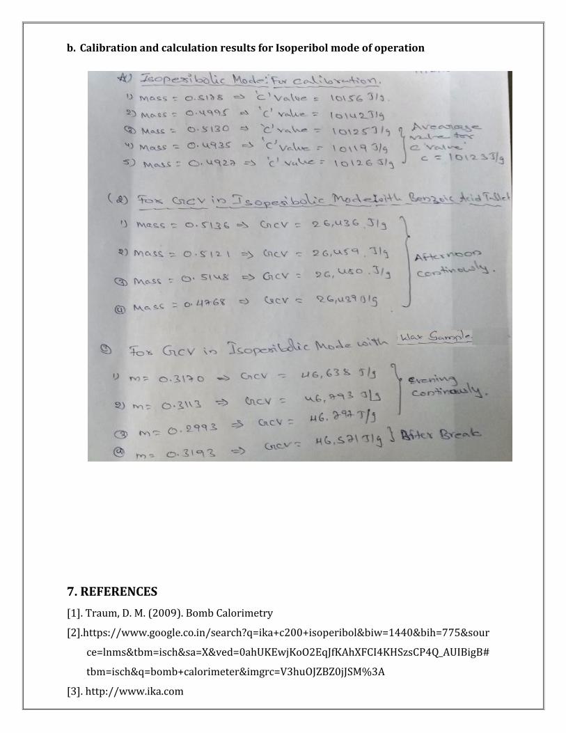
b. Calibration and calculation results for Isoperibol mode of operation
7. REFERENCES
[1]. Traum, D. M. (2009). Bomb Calorimetry
[2].https://www.google.co.in/search?q=ika+c200+isoperibol&biw=1440&bih=775&sour
ce=lnms&tbm=isch&sa=X&ved=0ahUKEwjKoO2EqJfKAhXFCI4KHSzsCP4Q_AUIBigB#
tbm=isch&q=bomb+calorimeter&imgrc=V3huOJZBZ0jJSM%3A
[3]. http://www.ika.com