prosa tools - christoph miethke gmbh & co. kg e gravitationseinheit des prosa ist in der...
TRANSCRIPT

proSA Tools
0297CHRISTOPH MIETHKE GMBH & CO. KG
Gebrauchsanweisung | Instructions for use
This Instructions for Use is NOT intended for United State users. Please discard. The Instructions for Use for United States users can be obtained by visiting our website at www.aesculapusa.com and clicking the "Products" menu. If you wish to obtain a paper copy of the Instructions for Use, you may request one by contacting your local Aesculap representative or Aesculap's customer service at 1-800-282-9000. A paper copy will be provided to you upon request at no additional cost.
D GB
USA

3
proSA Instrumente | D
InhaltsverzeIchnIs
INdIkATION 4proSA Prüfinstrument 4proSA Masterdisc 4proSA Kompass 4proSA Verstellinstrument 5proSA Verstellscheibe 5TechNISche BeSchreIBUNG 6PhySIkAlIScher hINTerGrUNd 7ArBeITSweISe deS veNTIlS 8dIe wAhl deS GeeIGNeTeN ÖffNUNGSdrUckeS 10eINSTellUNG deS veNTIlS 12drUckSTUfeNerkeNNUNG Im rÖNTGeNBIld 14proSA Verstellkreisel 0297 15reINIGUNG UNd deSINfekTION deS proSA Verstellkreisels 15STerIlISIerBArkeIT 17emPfehlUNG zUr STerIlISATION deS proSA Verstellkreisel 17reINIGUNGSemPfehlUNG für dIe NIchT-STerIlISIerBAreN proSA Instrumente 17medIzINPrOdUkTeBerATer 17AllGemeINe INfOrmATIONeN 17
4 5
| proSA Instrumente proSA Instrumente | DD
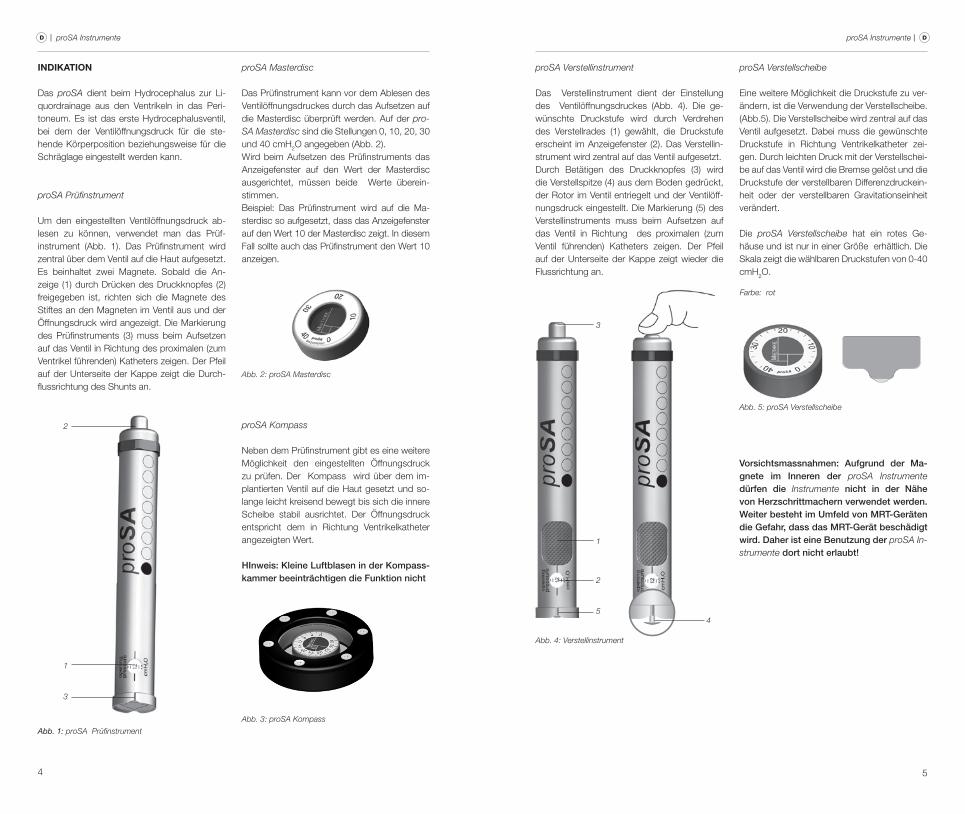
proSA Masterdisc
das Prüfinstrument kann vor dem Ablesen des ventilöffnungsdruckes durch das Aufsetzen auf die masterdisc überprüft werden. Auf der pro-SA Masterdisc sind die Stellungen 0, 10, 20, 30 und 40 cmh2O angegeben (Abb. 2). wird beim Aufsetzen des Prüfinstruments das Anzeigefenster auf den wert der masterdisc ausgerichtet, müssen beide werte überein-stimmen.Beispiel: das Prüfinstrument wird auf die ma-sterdisc so aufgesetzt, dass das Anzeigefenster auf den wert 10 der masterdisc zeigt. In diesem fall sollte auch das Prüfinstrument den wert 10 anzeigen.
Abb. 2: proSA Masterdisc
proSA Kompass
Neben dem Prüfinstrument gibt es eine weitere möglichkeit den eingestellten Öffnungsdruck zu prüfen. der kompass wird über dem im-plantierten ventil auf die haut gesetzt und so-lange leicht kreisend bewegt bis sich die innere Scheibe stabil ausrichtet. der Öffnungsdruck entspricht dem in richtung ventrikelkatheter angezeigten wert.
HInweis: Kleine Luftblasen in der Kompass-kammer beeinträchtigen die Funktion nicht
Abb. 3: proSA Kompass
IndIkatIon
das proSA dient beim hydrocephalus zur li-quordrainage aus den ventrikeln in das Peri-toneum. es ist das erste hydrocephalusventil, bei dem der ventilöffnungsdruck für die ste-hende körperposition beziehungsweise für die Schräglage eingestellt werden kann.
proSA Prüfinstrument
Um den eingestellten ventilöffnungsdruck ab-lesen zu können, verwendet man das Prüf-instrument (Abb. 1). das Prüfinstrument wird zentral über dem ventil auf die haut aufgesetzt. es beinhaltet zwei magnete. Sobald die An-zeige (1) durch drücken des druckknopfes (2) freigegeben ist, richten sich die magnete des Stiftes an den magneten im ventil aus und der Öffnungsdruck wird angezeigt. die markierung des Prüfinstruments (3) muss beim Aufsetzen auf das ventil in richtung des proximalen (zum ventrikel führenden) katheters zeigen. der Pfeil auf der Unterseite der kappe zeigt die durch-flussrichtung des Shunts an.
Abb. 1: proSA Prüfinstrument
2
1
3
proSA Verstellinstrument
das verstellinstrument dient der einstellung des ventilöffnungsdruckes (Abb. 4). die ge-wünschte druckstufe wird durch verdrehen des verstellrades (1) gewählt, die druckstufe erscheint im Anzeigefenster (2). das verstellin-strument wird zentral auf das ventil aufgesetzt. durch Betätigen des druckknopfes (3) wird die verstellspitze (4) aus dem Boden gedrückt, der rotor im ventil entriegelt und der ventilöff-nungsdruck eingestellt. die markierung (5) des verstellinstruments muss beim Aufsetzen auf das ventil in richtung des proximalen (zum ventil führenden) katheters zeigen. der Pfeil auf der Unterseite der kappe zeigt wieder die flussrichtung an.
3
1
2
5
Abb. 4: Verstellinstrument
4
proSA Verstellscheibe
eine weitere möglichkeit die druckstufe zu ver-ändern, ist die verwendung der verstellscheibe.(Abb.5). die verstellscheibe wird zentral auf das ventil aufgesetzt. dabei muss die gewünschte druckstufe in richtung ventrikelkatheter zei-gen. durch leichten druck mit der verstellschei-be auf das ventil wird die Bremse gelöst und die druckstufe der verstellbaren differenzdruckein-heit oder der verstellbaren Gravitationseinheit verändert.
die proSA Verstellscheibe hat ein rotes Ge-häuse und ist nur in einer Größe erhältlich. die Skala zeigt die wählbaren druckstufen von 0-40 cmh2O.
Abb. 5: proSA Verstellscheibe
Farbe: rot
Vorsichtsmassnahmen: Aufgrund der Ma-gnete im Inneren der proSA Instrumente dürfen die Instrumente nicht in der Nähe von Herzschrittmachern verwendet werden. Weiter besteht im Umfeld von MRT-Geräten die Gefahr, dass das MRT-Gerät beschädigt wird. Daher ist eine Benutzung der proSA In-strumente dort nicht erlaubt!
6 7
| proSA Instrumente proSA Instrumente | DD
technIsche BeschreIBung
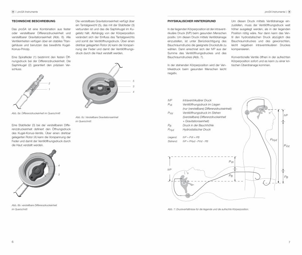
das proSA ist eine kombination aus fester oder verstellbarer differenzdruckeinheit und verstellbarer Gravitationseinheit (Abb. 6). Alle ventileinheiten verfügen über ein stabiles Titan-gehäuse und benutzen das bewährte kugel-konus-Prinzip.
eine Spiralfeder (1) bestimmt den festen Öff-nungsdruck bei der differenzdruckeinheit. die Saphirkugel (2) garantiert den präzisen ver-schluss.
2
1
Abb. 6a: Differenzdruckeinheit im Querschnitt
eine Stabfeder (3) bei der verstellbaren diffe-renzdruckeinheit definiert den Öffnungsdruck des kugel-konus-ventils. über einen drehbar gelagerten rotor (4) kann die vorspannung der feder und damit der ventilöffnungsdruck durch die haut verstellt werden.
4
3
Abb. 6b: verstellbare Differenzdruckeinheit
im Querschnitt
die verstellbare Gravitationseinheit verfügt über ein Tantalgewicht (5), das mit der Stabfeder (3) verbunden ist und das die Saphirkugel im ku-gelsitz hält. Abhängig von der körperposition verändert sich der einfluss des Tantalgewichts und somit der ventilöffnungsdruck. über einen drehbar gelagerten rotor (4) kann die vorspan-nung der feder und damit der ventilöffnungs-druck durch die haut verstellt werden.
Abb. 6c: Verstellbare Gravitationseinheit
im Querschnitt
PhysIkalIscher hIntergrund
In der liegenden körperposition ist der intravent-rikuläre druck (IvP) beim gesunden menschen positiv. Um diesen druck mit tels ventildrainage einzustellen, ist unter Berücksichtigung des Bauchraumdrucks die geeignete druckstufe zu wählen. dann errechnet sich der IvP aus der Summe des ventilöffnungsdruckes und des Bauchraumdruckes (Abb. 7).
In der stehenden körperposition wird der ven-trikeldruck beim gesunden menschen leicht negativ.
Um diesen druck mittels ventildrainage ein-zustellen, muss der ventilöffnungsdruck weit höher ausgelegt werden, als in der liegenden Position nötig wäre. Nur dann kann das ven-til den hydrostatischen druck abzüglich des Bauchraumdruckes und des gewünschten, leicht negativen intraventrikulären druckes kompensieren.
konventionelle ventile öffnen in der aufrechten körperposition sofort und es kann zu einer kri-tischen überdrainage kommen.
CH
RIS
TOP
H M
IETH
KE
0...4
0
proSA
CHRISTOPH MIETHKE0...40
proSA
IVP
PVli
PB
PHyd
PVst
IVP
PB
Abb. 7: Druckverhältnisse für die liegende und die aufrechte Körperposition.
Liegend: IVP = PVli + PB
Stehend: IVP = PHyd - PVst - PB
IVP Intraventrikulärer DruckPVli Ventilöffnungsdruck im Liegen (nur (verstellbare) Differenzdruckeinheit)PVst Ventilöffnungsdruck im Stehen ((verstellbare) Differenzdruckeinheit + Gravitationseinheit)PB Druck in der BauchhöhlePHyd Hydrostatischer Druck
5
3
4

8 9
| proSA Instrumente proSA Instrumente | DD
arBeItsweIse des ventIls
Horizontale Körperposition
proSA mit differenzdruckeinheit
In der Abb. 8a ist die differenzdruckeinheit geschlossen. es ist keine drainage möglich. wenn der intraventrikuläre druck erhöht ist, wird die federkraft, die das kugel-konus-ventil sonst geschlossen hält, überwunden. die fe-der wird komprimiert, die verschlusskugel be-wegt sich aus dem konus und ein Spalt zur liquordrainage wird freigegeben. (Abb.3b)
Abb. 8: Differenzdruckeinheit a) geschlossen und b) geöffnet
a)
b)
proSA mit verstellbarer differenzdruckeinheit
das kugel-konus-ventil der verstellbaren diffe-renzdruckeinheit ist in Abb. 9a geschlossen, es ist keine drainage möglich. In Abb. 9b ist die verstellbare differenzdruckeinheit geöffnet. der intraventrikuläre druck (IvP) des Patienten ist erhöht und die federkraft, die das kugel-ko-nus-ventil sonst geschlossen hält, ist überwun-den. Jetzt bewegt sich die verschlusskugel aus dem konus und ein Spalt zur liquordrainage wird freigegeben.
Abb. 9: verstellbare Differenzdruckeinheit a) geschlossen, b) offen
a)
b)
In horizontaler Position wirkt das Gewicht (1) nicht gegen die verschlusskugel (2), die ver-stellbare Gravitationseinheit des proSA ist in der liegendposition somit immer geöffnet und stellt keinen widerstand für das abfließende hirn-wasser dar: der Öffnungsdruck des proSA wird in der horizontalen körperposition ausschließ-lich von der differenzdruckeinheit bestimmt.
2
1
Abb. 10: verstellbare Gravitationseinheit in horizontaler Position
Vertikale Körperposition In senkrechter Position setzt sich der Ge samt-ventilöffnungsdruck aus dem Öff nungs druck der (verstellbaren) differenz druckeinheit und der verstellbaren Gravitationseinheit zusammen. übersteigt die Sum me aus IvP und hydro-statischem druck den Gesamtventilöffnungs-druck, bewegt sich die verschlusskugel in bei-den einheiten aus dem konus und ein Spalt zur
liquordrainage wird freigegeben (Abb. 11). ein weiterer druckanstieg in den hirnkammern wird somit verhindert.
Um die optimale individuelle Anpassung für den Patienten zu gewährleisten, kann bei der verstellbaren Gravitationseinheit ein ventilöff-nungsdruck zwischen 0 und 40 cmh2O gewählt werden.
b)a)
Abb. 11: Gravitationseinheit in senkrechter Körperhaltung a) geschlossen b) offen

10 11
| proSA Instrumente proSA Instrumente | DD
Horizontale Körperposition:In der liegenden Position übt die Gravitations-einheit keinen einfluss auf den ventilöffnungs-druck des Shuntsystems aus. die differenzdruckeinheit bestimmt in dieser körperposition somit alleine den ventilöffnungs-druck im gesamten Shuntsystem. Als Standard wird eine differenzdruckeinheit mit Öffnungs-druck 5 cmh2O empfohlen:
dIe wahl des geeIgneten Öffnungsdruckes
das proSA ist ein lageabhängig arbeitendes ventil, d. h. der Öffnungsdruck ändert sich mit der körperposition des Patienten. Um das pro-SA individuell dem Patienten anzupassen, wird ein Öffnungsdruck für die horizontale und verti-kale körperposition des Patienten gewählt. (siehe auch druckstufenempfehlung unter www.miethke.com)
Öffnungsdruck der differenzdruckeinheit
Öffnungsdruck der Gravitationseinheit
Öffnungsdruck des gesamten Shuntsystems
Standard5 cmh2O
0 cmh2Odefensiv*10 cmh2O
Spezial**15 cmh2O
*bei Patienten mit extrem weiten Ventrikeln, Aquäduktstenosen oder stark erhöhtem ICP
**Patienten mit Pseudotumor cerebri
= +
Vertikale Körperposition:der Öffnungsdruck des gesamten Shunt- systems in der stehenden Position ist die Sum-me aus dem Öffnungsdruck der differenzdruck-einheit und dem der Gravitationseinheit. der Öffnungsdruck der Gravitationseinheit sollte abhängig von körpergröße, körpergewicht und dem Alter des Patienten gewählt und eingestellt werden.
Öffnungsdruck der differenzdruckeinheit
empfohlene einstellung des Öffnungs-drucks für die Gravitationseinheit
Öffnungsdruck des gesamten Shuntsystems
Öffnungsdruck der differenz- druckeinheit
kinder bis 5 Jahre 20 cmh2O
aktive erwachsene jünger als 60 Jahre
25 cmh2O
erwachsene älter als 60 Jahre20 cmh2O
Unsere Druckstufenempfehlungen sind unverbindliche Richtwerte.
Andere Werte können, abhängig vom Patienten und seiner individuellen Krankengeschichte, angezeigt sein.
= +
12 13
| proSA Instrumente proSA Instrumente | DD
eInstellung des ventIls
Hinweis: Für die Lokalisierung, das Prüfen und das Verstellen der verstellbaren Dif-ferenzdruckeinheit und der verstellbaren Gravitationseinheit gibt es unterschiedliche Prüf- und Verstellinstrumente.
Instrumente für die verstellbare Differenzdruckeinheit: proGAV PrüfinstrumentproGAV MasterdiscproGAV KompassproGAV VerstellinstrumentproGAV VerstellscheibeproGAV Verstellkreisel
Instrumente für die verstellbare Gravitationseinheit: proSA PrüfinstrumentproSA MasterdiscproSA KompassproSA VerstellinstrumentproSA VerstellscheibeproSA Verstellkreisel
es ist unbedingt erforderlich, sich vor der Benut-zung der Instrumente zu vergewissern, dass: für die verstellbare differenzdruckeinheit aus-schließlich proGAV Instrumente
und für die verstellbare Gravitationseinheit aus-schließlich proSA Instrumente
verwendet werden!
Um eine verstellung der verstellbaren Gravita-tionseinheit durchzuführen, müssen folgende Schritte ausgeführt werden:
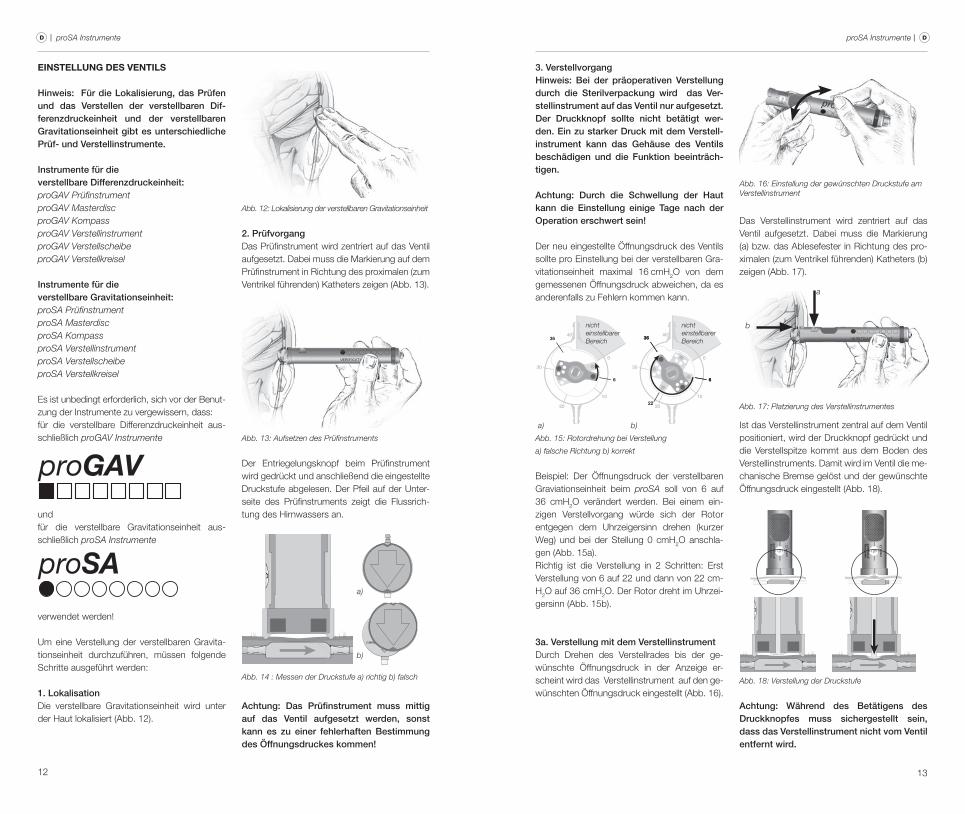
1. Lokalisationdie verstellbare Gravitationseinheit wird unter der haut lokalisiert (Abb. 12).
Abb. 12: Lokalisierung der verstellbaren Gravitationseinheit
2. Prüfvorgang das Prüfinstrument wird zentriert auf das ventil aufgesetzt. dabei muss die markierung auf dem Prüfinstrument in richtung des proximalen (zum ventrikel führenden) katheters zeigen (Abb. 13).
Abb. 13: Aufsetzen des Prüfinstruments
der entriegelungsknopf beim Prüfinstrument wird gedrückt und anschließend die eingestellte druckstufe abgelesen. der Pfeil auf der Unter-seite des Prüfinstruments zeigt die flussrich-tung des hirnwassers an.
Abb. 14 : Messen der Druckstufe a) richtig b) falsch
CHRISTOPH MIETHKE
0...20p ro G A V
a)
b)
Achtung: Das Prüfinstrument muss mittig auf das Ventil aufgesetzt werden, sonst kann es zu einer fehlerhaften Bestimmung des Öffnungsdruckes kommen!
3. VerstellvorgangHinweis: Bei der präoperativen Verstellung durch die Sterilverpackung wird das Ver-stellinstrument auf das Ventil nur aufgesetzt. Der Druckknopf sollte nicht betätigt wer-den. Ein zu starker Druck mit dem Verstell- instrument kann das Gehäuse des Ventils beschädigen und die Funktion beeinträch-tigen.
Achtung: Durch die Schwellung der Haut kann die Einstellung einige Tage nach der Operation erschwert sein!
der neu eingestellte Öffnungsdruck des ventils sollte pro einstellung bei der verstellbaren Gra-vitationseinheit maximal 16 cmh2O von dem gemessenen Öffnungsdruck abweichen, da es anderenfalls zu fehlern kommen kann.
Abb. 15: Rotordrehung bei Verstellung
a) falsche Richtung b) korrekt
10
2022
30
40
0
36
6
36
6
10
20
30
40
0
6
36
a) b)
nicht einstellbarer Bereich
nicht einstellbarer Bereich
Beispiel: der Öffnungsdruck der verstellbaren Graviationseinheit beim proSA soll von 6 auf 36 cmh2O verändert werden. Bei einem ein-zigen verstellvorgang würde sich der rotor entgegen dem Uhrzeigersinn drehen (kurzer weg) und bei der Stellung 0 cmh2O anschla-gen (Abb. 15a).richtig ist die verstellung in 2 Schritten: erst verstellung von 6 auf 22 und dann von 22 cm-h2O auf 36 cmh2O. der rotor dreht im Uhrzei-gersinn (Abb. 15b).
3a. Verstellung mit dem Verstellinstrumentdurch drehen des verstellrades bis der ge-wünschte Öffnungsdruck in der Anzeige er-scheint wird das verstellinstrument auf den ge-wünschten Öffnungsdruck eingestellt (Abb. 16).
Abb. 16: Einstellung der gewünschten Druckstufe am Verstellinstrument
das verstellinstrument wird zentriert auf das ventil aufgesetzt. dabei muss die markierung (a) bzw. das Ablesefester in richtung des pro-ximalen (zum ventrikel führenden) katheters (b) zeigen (Abb. 17).
a
b
Abb. 17: Platzierung des Verstellinstrumentes
Ist das verstellinstrument zentral auf dem ventil positioniert, wird der druckknopf gedrückt und die verstellspitze kommt aus dem Boden des verstellinstruments. damit wird im ventil die me-chanische Bremse gelöst und der gewünschte Öffnungsdruck eingestellt (Abb. 18).
Abb. 18: Verstellung der Druckstufe
Achtung: Während des Betätigens des Druckknopfes muss sichergestellt sein, dass das Verstellinstrument nicht vom Ventil entfernt wird.
14 15
| proSA Instrumente proSA Instrumente | DD
Bei empfindlichen Patienten ist die verwendung lokaler Betäubung während des verstellvor-gangs zu prüfen (z. B. durch Pflaster), sofern keine kontraindikation vorliegt.
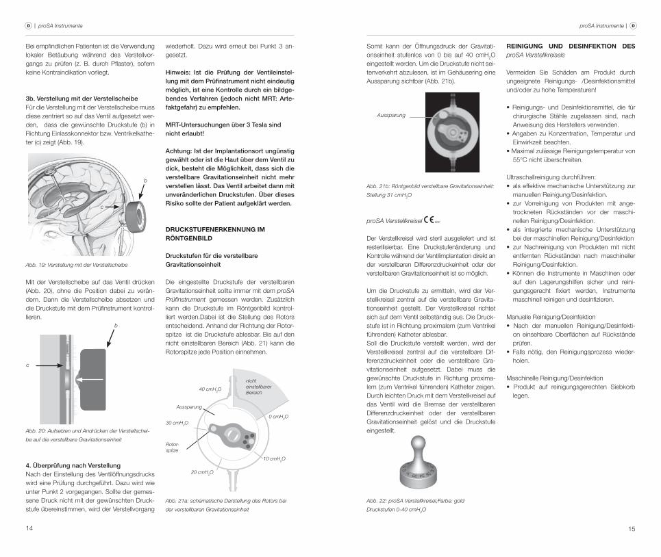
3b. Verstellung mit der Verstellscheibefür die verstellung mit der verstellscheibe muss diese zentriert so auf das ventil aufgesetzt wer-den, dass die gewünschte druckstufe (b) in richtung einlasskonnektor bzw. ventrikelkathe-ter (c) zeigt (Abb. 19).
Abb. 19: Verstellung mit der Verstellscheibe
b
c
mit der verstellscheibe auf das ventil drücken (Abb. 20), ohne die Position dabei zu verän-dern. dann die verstellscheibe absetzen und die druckstufe mit dem Prüfinstrument kontrol-lieren.
Abb. 20: Aufsetzen und Andrücken der Verstellschei-
be auf die verstellbare Gravitationseinheit
b
c
4. Überprüfung nach VerstellungNach der einstellung des ventilöffnungsdrucks wird eine Prüfung durchgeführt. dazu wird wie unter Punkt 2 vorgegangen. Sollte der gemes-sene druck nicht mit der gewünschten druck-stufe übereinstimmen, wird der verstellvorgang
wiederholt. dazu wird erneut bei Punkt 3 an-gesetzt.
Hinweis: Ist die Prüfung der Ventileinstel-lung mit dem Prüfinstrument nicht eindeutig möglich, ist eine Kontrolle durch ein bildge-bendes Verfahren (jedoch nicht MRT: Arte-faktgefahr) zu empfehlen.
MRT-Untersuchungen über 3 Tesla sindnicht erlaubt!
Achtung: Ist der Implantationsort ungünstig gewählt oder ist die Haut über dem Ventil zu dick, besteht die Möglichkeit, dass sich die verstellbare Gravitationseinheit nicht mehr verstellen lässt. Das Ventil arbeitet dann mit unveränderlichen Druckstufen. Über dieses Risiko sollte der Patient aufgeklärt werden.
druckstufenerkennung Im rÖntgenBIld
Druckstufen für die verstellbare Gravitationseinheit
die eingestellte druckstufe der verstellbaren Gravitationseinheit sollte immer mit dem proSA Prüfinstrument gemessen werden. zusätzlich kann die druckstufe im röntgenbild kontrol-liert werden.dabei ist die Stellung des rotors entscheidend. Anhand der richtung der rotor-spitze ist die druckstufe ablesbar. Bis auf den nicht einstellbaren Bereich (Abb. 21) kann die rotorspitze jede Position einnehmen.
Abb. 21a: schematische Darstellung des Rotors bei
der verstellbaren Gravitationseinheit
Rotor-spitze
Aussparung
30 cmH2O
40 cmH2O
20 cmH2O
10 cmH2O
0 cmH2O
nichteinstellbarer Bereich
Somit kann der Öffnungsdruck der Gravitati-onseinheit stufenlos von 0 bis auf 40 cmh2O eingestellt werden. Um die druckstufe nicht sei-tenverkehrt abzulesen, ist im Gehäusering eine Aussparung sichtbar (Abb. 21b).
Aussparung
Abb. 21b: Röntgenbild verstellbare Gravitationseinheit:
Stellung 31 cmH2O
proSA Verstellkreisel 0297
der verstellkreisel wird steril ausgeliefert und ist resterilisierbar. eine druckstufenänderung und kontrolle während der ventilimplantation direkt an der verstellbaren differenzdruckeinheit oder der verstellbaren Gravitationseinheit ist so möglich.
Um die druckstufe zu ermitteln, wird der ver-stellkreisel zentral auf die verstellbare Gravita-tionseinheit gestellt. der verstellkreisel richtet sich auf dem ventil selbständig aus. die druck-stufe ist in richtung proximalem (zum ventrikel führenden) katheter ablesbar. Soll die druckstufe verstellt werden, wird der verstellkreisel zentral auf die verstellbare dif-ferenzdruckeinheit oder die verstellbare Gra-vitationseinheit aufgesetzt. dabei muss die gewünschte druckstufe in richtung proxima-lem (zum ventrikel führenden) katheter zeigen. durch leichten druck mit dem verstellkreisel auf das ventil wird die Bremse der verstellbaren differenzdruckeinheit oder der verstellbaren Gravitationseinheit gelöst und die druckstufe eingestellt.
Abb. 22: proSA Verstellkreisel,Farbe: gold
Druckstufen 0-40 cmH2O
reInIgung und desInfektIon des proSA Verstellkreisels
vermeiden Sie Schäden am Produkt durch ungeeignete reinigungs- /desinfektionsmittel und/oder zu hohe Temperaturen!
• Reinigungs- und Desinfektionsmittel, die für chirurgische Stähle zugelassen sind, nach Anweisung des herstellers verwenden.
• Angaben zu Konzentration, Temperatur und einwirkzeit beachten.
• Maximal zulässige Reinigungstemperatur von 55°c nicht überschreiten.
Ultraschallreinigung durchführen:• als effektive mechanische Unterstützung zur
manuellen reinigung/desinfektion.• zur Vorreinigung von Produkten mit ange-
trockneten rückständen vor der maschi-nellen reinigung/desinfektion.
• als integrierte mechanische Unterstützung bei der maschinellen reinigung/desinfektion
• zur Nachreinigung von Produkten mit nicht entfernten rückständen nach maschineller reinigung/desinfektion.
• Können die Instrumente in Maschinen oder auf den lagerungshilfen sicher und reini-gungsgerecht fixiert werden, Instrumente maschinell reinigen und desinfizieren.
manuelle reinigung/desinfektion• Nach der manuellen Reinigung/Desinfekti-
on einsehbare Oberflächen auf rückstände prüfen.
• Falls nötig, den Reinigungsprozess wieder-holen.
maschinelle reinigung/desinfektion• Produkt auf reinigungsgerechten Siebkorb
legen.
16 17
| proSA Instrumente proSA Instrumente | DD
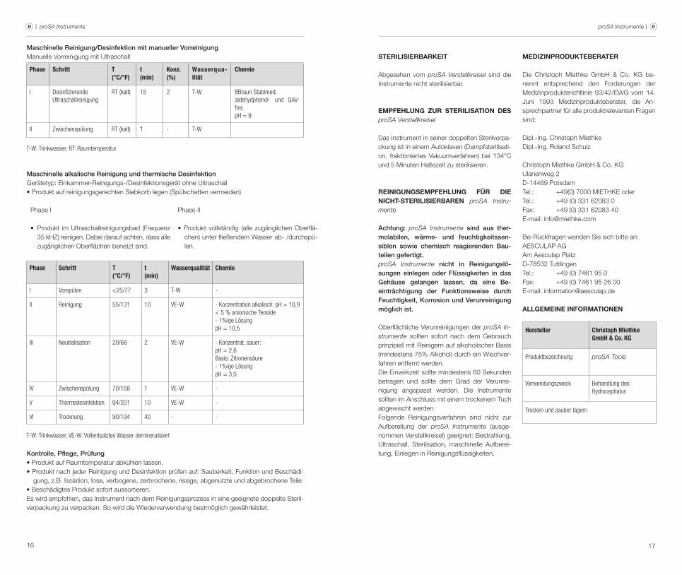
Maschinelle Reinigung/Desinfektion mit manueller Vorreinigungmanuelle vorreinigung mit Ultraschall
Phase Schritt T(°C/°F)
t(min)
Konz.(%)
Wasserqua-lität
Chemie
I Desinfizierende Ultraschallreinigung
RT (kalt) 15 2 T-W BBraun Stabimed; aldehydphenol- und QAV-frei;pH = 9
II Zwischenspülung RT (kalt) 1 - T-W
T-W: Trinkwasser, RT: Raumtemperatur
Maschinelle alkalische Reinigung und thermische DesinfektionGerätetyp: einkammer-reinigungs-/desinfektionsgerät ohne Ultraschall• Produkt auf reinigungsgerechten Siebkorb legen (Spülschatten vermeiden)
Phase I Phase II
• Produkt im Ultraschallreinigungsbad (Frequenz 35 khz) reinigen. dabei darauf achten, dass alle zugänglichen Oberflächen benetzt sind.
• Produkt vollständig (alle zugänglichen Oberflä-chen) unter fließendem wasser ab- /durchspü-len.
Phase Schritt T(°C/°F)
t(min)
Wasserqualität Chemie
I Vorspülen <25/77 3 T-W -
II Reinigung 55/131 10 VE-W - Konzentration alkalisch: pH = 10,9< 5 % anionische Tenside- 1%ige LösungpH = 10,5
III Neutralisation 20/68 2 VE-W - Konzentrat, sauer:pH = 2,6Basis: Zitronensäure- 1%ige LösungpH = 3,0
IV Zwischenspülung 70/158 1 VE-W -
V Thermodesinfektion 94/201 10 VE-W -
VI Trocknung 90/194 40 - -
T-W: Trinkwasser, VE-W: Vollentsalztes Wasser demineralisiert
Kontrolle, Pflege, Prüfung• Produkt auf Raumtemperatur abkühlen lassen.• Produkt nach jeder Reinigung und Desinfektion prüfen auf: Sauberkeit, Funktion und Beschädi-
gung, z.B. Isolation, lose, verbogene, zerbrochene, rissige, abgenutzte und abgebrochene Teile.• Beschädigtes Produkt sofort aussortieren.es wird empfohlen, das Instrument nach dem reinigungsprozess in eine geeignete doppelte Steril-verpackung zu verpacken. So wird die wiederverwendung bestmöglich gewährleistet.
sterIlIsIerBarkeIt
Abgesehen vom proSA Verstellkreisel sind die Instrumente nicht sterilisierbar.
emPfehlung zur sterIlIsatIon des proSA Verstellkreisel
das Instrument in seiner doppelten Sterilverpa-ckung ist in einem Autoklaven (dampfsterilisati-on, fraktioniertes vakuumverfahren) bei 134°c und 5 minuten haltezeit zu sterilisieren.
reInIgungsemPfehlung für dIe nIcht-sterIlIsIerBaren proSA Instru-mente
Achtung: proSA Instrumente sind aus ther-molabilen, wärme- und feuchtigkeitssen-siblen sowie chemisch reagierenden Bau-teilen gefertigt.proSA Instrumente nicht in Reinigungslö-sungen einlegen oder Flüssigkeiten in das Gehäuse gelangen lassen, da eine Be-einträchtigung der Funktionsweise durch Feuchtigkeit, Korrosion und Verunreinigung möglich ist.
Oberflächliche verunreinigungen der proSA In-strumente sollten sofort nach dem Gebrauch prinzipiell mit reinigern auf alkoholischer Basis (mindestens 75% Alkohol) durch ein wischver-fahren entfernt werden.die einwirkzeit sollte mindestens 60 Sekunden betragen und sollte dem Grad der verunrei-nigung angepasst werden. die Instrumente sollten im Anschluss mit einem trockenem Tuch abgewischt werden.folgende reinigungsverfahren sind nicht zur Aufbereitung der proSA Instrumente (ausge-nommen verstellkreisel) geeignet: Bestrahlung, Ultraschall, Sterilisation, maschinelle Aufberei-tung, einlegen in reinigungsflüssigkeiten.
medIzInProdukteBerater
die christoph miethke Gmbh & co. kG be-nennt entsprechend den forderungen der medizinprodukterichtlinie 93/42/ewG vom 14. Juni 1993 medizinprodukteberater, die An-sprechpartner für alle produktrelevanten fragen sind:
dipl.-Ing. christoph miethke dipl.-Ing. roland Schulz
christoph miethke Gmbh & co. kGUlanenweg 2d-14469 PotsdamTel.: +49(0) 7000 mIeThke oderTel.: +49 (0) 331 62083 0fax: +49 (0) 331 62083 40e-mail: [email protected]
Bei rückfragen wenden Sie sich bitte an:AeScUlAP AG Am Aesculap Platzd-78532 TuttlingenTel.: +49 (0) 7461 95 0fax: +49 (0) 7461 95 26 00e-mail: [email protected]
allgemeIne InformatIonen
Hersteller Christoph Miethke GmbH & Co. KG
Produktbezeichnung proSA Tools
Verwendungszweck Behandlung des Hydrocephalus
Trocken und sauber lagern
19
proSA Tools | GB
18
content
INdIcATION 20proSA Verification Tool 20proSA Masterdisc 20proSA Compass 20proSA Adjustment Tool 21proSA Adjustment Disc 21TechNIcAl deScrIPTION 22PhySIcS BAckGrOUNd 23fUNcTION Of The vAlve 24SelecTING The APPrOPrIATe OPeNING PreSSUre Of The vAlve 26AdJUSTING The vAlve 28reAdING The PreSSUre SeTTING frOm AN X-rAy ImAGe 30proSA Check-mate 0297 31cleANING ANd dISINfecTING The proSA Check-mate 31recOmmeNdATION fOr STerIlISATION Of The proSA Check-mate 32cleANING recOmmeNdATION fOr proSA Tools whIch Are NOT STerIlISABle 32medIcAl PrOdUcTS cONSUlTANT 32GeNerAl INfOrmATION 32

20 21
| proSA Tools proSA Tools | GB GB
proSA Masterdisc
The verification tool can be easily checked by using the proSA Masterdisc before measu-ring the opening pressure of the valve. On the proSA Masterdisc the positions 0, 10, 20, 30 and 40 cmh2O (fig. 2) are indica-ted. If the verification tool is placed on the disc the opening pressure shown by the in-strument should be aligned to the value of the proSA Masterdisc.
example: The verification tool is put on the ma-sterdisc so that the marking on the instrument is in line with the value 10 cmh2O on the Ma-sterdisc. The verification tool should indicate the value of 10 cmh2O.
Fig. 2: proSA Masterdisc
proSA Compass
Alongside the verification tool there is an addi-tional device for checking the adjusted opening pressure. The compass can be used to locate the valve when palpation is not possible. The compass is set to the skin above the implanted valve. The opening pressure corresponds to the value indicated towards the direction of the ventricular catheter.
Fig. 3: proSA Compass
Caution: Airbubbles inside the compass do not affect its functionality.
IndIcatIon
The proSA is intended to divert cerebrospinal fluid (cSf) from the lateral ventricles of the brain into the peritoneum. It is the first hydrocepha-lus valve that is adjustable for the vertical body position, respectively for inclined body position.
proSA Verification Tool
The verification tool is used for reading the valve opening pressure setting (fig. 1). first-ly, it is essential that the verification tool is placed centrally over the valve. The notch (3) on the verification tool must be in line with the proximal (ventricular) catheter. The tool contains two magnets. As soon as the button (2) on the instrument is pushed the magnets in the tool align with the magnets in the valve. The opening pressure is shown on the scale (1). The arrow on the un-derside of the verification tool should be aligned with the direction of flow.
Fig. 1: proSA Verification Tool
2
1
3
proSA Adjustment Tool
The adjustment tool is used for adjusting the val-ve opening pressure. first the intended pressure setting is selected at the knurled dial (1), the ope-ning pressure is shown on a scale (2). Then the adjustment tool is placed centrally on the valve. By pushing the button (3), the adjustment tip (4) appears, the brake is decoupled, the rotor turns and the adjusted pressure is set. The marking (5) on the adjustment tool has to point towards the proximal catheter (leading to the ventricle).
3
1
2
5
Fig. 4: proSA Adjustment Tool
4
proSA Adjustment Disc
The adjustment disc offers another option to adjust the pressure setting (fig. 5). The adjust-ment disc is placed centrally over the valve. The desired pressure setting should be aligned with the proximal catheter (leading to the ventricle). By pressing down the adjustment disc on the valve, the brake is decoupled and the opening pressure of the valve is changed.
Fig. 5: proSA Adjustment Discone size only
colour: red
Caution: Do not use the proSA Tools nearby MRI scanner, since there is a danger of da-maging the MRI scanner due to the magnets inside the proSA Tools.
Warning note for carriers of pacemakers: The magnets inside the proSA Tools can alter the function of a pacemaker.
22 23
| proSA Tools proSA Tools | GB GB
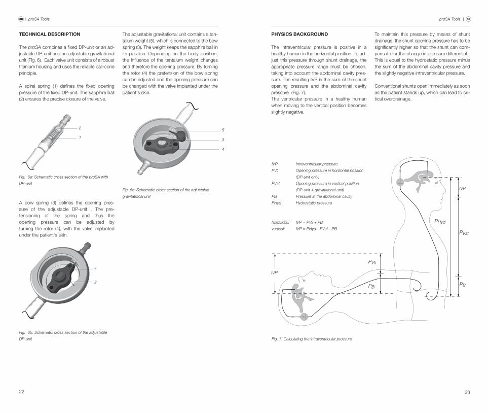
technIcal descrIPtIon
The proSA combines a fixed dP-unit or an ad-justable dP-unit and an adjustable gravitational unit (fig. 6). each valve unit consists of a robust titanium housing and uses the reliable ball-cone principle.
A spiral spring (1) defines the fixed opening pressure of the fixed dP-unit. The sapphire ball (2) ensures the precise closure of the valve.
2
1
Fig. 6a: Schematic cross section of the proSA with
DP-unit
A bow spring (3) defines the opening pres-sure of the adjustable dP-unit . The pre-tensioning of the spring and thus the opening pressure can be adjusted by turning the rotor (4), with the valve implanted under the patient‘s skin.
4
3
Fig. 6b: Schematic cross section of the adjustable
DP-unit
The adjustable gravitational unit contains a tan-talum weight (5), which is connected to the bow spring (3). The weight keeps the sapphire ball in its position. depending on the body position, the influence of the tantalum weight changes and therefore the opening pressure. By turning the rotor (4) the pretension of the bow spring can be adjusted and the opening pressure can be changed with the valve implanted under the patient‘s skin.
5
3
4
Fig. 6c: Schematic cross section of the adjustable
gravitational unit
PhysIcs Background
The intraventricular pressure is positive in a healthy human in the horizontal position. To ad-just this pressure through shunt drainage, the appropriate pressure range must be chosen, taking into account the abdominal cavity pres-sure. The resulting IvP is the sum of the shunt opening pressure and the abdominal cavity pressure (fig. 7). The ventricular pressure in a healthy human when moving to the vertical position becomes slightly negative.
To maintain this pressure by means of shunt drainage, the shunt opening pressure has to be significantly higher so that the shunt can com-pensate for the change in pressure differential. This is equal to the hydrostatic pressure minus the sum of the abdominal cavity pressure and the slightly negative intraventricular pressure.
conventional shunts open immediately as soon as the patient stands up, which can lead to cri-tical overdrainage.
CH
RIS
TOP
H M
IETH
KE
0...4
0
proSA
CHRISTOPH MIETHKE0...40
proSA
IVP
PVli
PB
PHyd
PVst
IVP
PB
Fig. 7: Calculating the intraventricular pressure
horizontal: IVP = PVli + PB
vertical: IVP = PHyd - PVst - PB
IVP Intraventricular pressure
PVli Opening pressure in horizontal position
(DP-unit only)
PVst Opening pressure in vertical position
(DP-unit + gravitational unit)
PB Pressure in the abdominal cavity
PHyd Hydrostatic pressure
24 25
| proSA Tools proSA Tools | GB GB
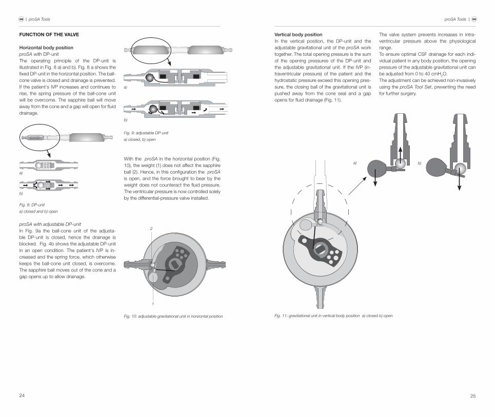
functIon of the valve
Horizontal body position proSA with dP-unitThe operating principle of the dP-unit is illustrated in fig. 8 a) and b). fig. 8 a shows the fixed dP-unit in the horizontal position. The ball-cone valve is closed and drainage is prevented. If the patient‘s IvP increases and continues to rise, the spring pressure of the ball-cone unit will be overcome. The sapphire ball will move away from the cone and a gap will open for fluid drainage.
Fig. 8: DP-unit
a) closed and b) open
a)
b)
proSA with adjustable DP-unitIn fig. 9a the ball-cone unit of the adjusta-ble dP-unit is closed, hence the drainage is blocked. fig. 4b shows the adjustable dP-unit in an open condition. The patient‘s IvP is in-creased and the spring force, which otherwise keeps the ball-cone unit closed, is overcome. The sapphire ball moves out of the cone and a gap opens up to allow drainage.
Fig. 9: adjustable DP-unit
a) closed, b) open
a)
b)
with the proSA in the horizontal position (fig. 10), the weight (1) does not affect the sapphire ball (2). hence, in this configuration the proSA is open, and the force brought to bear by the weight does not counteract the fluid pressure. The ventricular pressure is now controlled solely by the differential-pressure valve installed.
2
1
Fig. 10: adjustable gravitational unit in horizontal position
Vertical body positionIn the vertical position, the dP-unit and the adjustable gravitational unit of the proSA work together. The total opening pressure is the sum of the opening pressures of the dP-unit and the adjustable gravitational unit. If the IvP (in-traventricular pressure) of the patient and the hydrostatic pressure exceed this opening pres-sure, the closing ball of the gravitational unit is pushed away from the cone seal and a gap opens for fluid drainage (fig. 11).
The valve system prevents increases in intra-ventricular pressure above the physiological range.To ensure optimal cSf drainage for each indi-vidual patient in any body position, the opening pressure of the adjustable gravitational unit can be adjusted from 0 to 40 cmh2O. The adjustment can be achieved non-invasively using the proSA Tool Set, preventing the need for further surgery.
b)a)
Fig. 11: gravitational unit in vertical body position a) closed b) open
26 27
| proSA Tools proSA Tools | GB GB
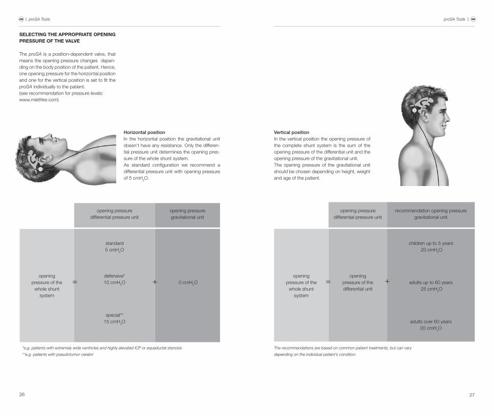
Horizontal positionIn the horizontal position the gravitational unit doesn‘t have any resistance. Only the differen-tial pressure unit determines the opening pres-sure of the whole shunt system. As standard configuration we recommend a differential pressure unit with opening pressure of 5 cmh2O.
selectIng the aPProPrIate oPenIng Pressure of the valve
The proSA is a position-dependent valve, that means the opening pressure changes depen-ding on the body position of the patient. hence, one opening pressure for the horizontal position and one for the vertical position is set to fit the proSA individually to the patient.(see recommendation for pressure levels: www.miethke.com)
opening pressuredifferential pressure unit
opening pressuregravitational unit
openingpressure of the
whole shuntsystem
standard5 cmh2O
0 cmh2Odefensive*10 cmh2O
special**15 cmh2O
*e.g. patients with extremely wide ventricles and highly elevated ICP or aqueductal stenosis
**e.g. patients with pseudotumor cerebri
= +
Vertical positionIn the vertical position the opening pressure of the complete shunt system is the sum of the opening pressure of the differential unit and the opening pressure of the gravitational unit. The opening pressure of the gravitational unit should be chosen depending on height, weight and age of the patient.
opening pressuredifferential pressure unit
recommendation opening pressuregravitational unit
openingpressure of the
whole shuntsystem
openingpressure of thedifferential unit
children up to 5 years 20 cmh2O
adults up to 60 years 25 cmh2O
adults over 60 years20 cmh2O
The recommendations are based on common patient treatments, but can vary
depending on the individual patient´s condition.
= +
28 29
| proSA Tools proSA Tools | GB GB
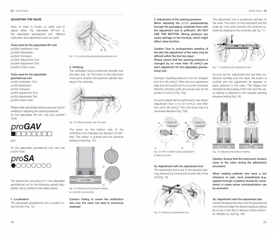
adjustIng the valve
Note: In order to locate, to verifiy and to adjust either the adjustable dP-unit or the adjustable gravitational unit, different verification and adjustment tools are used:
Tools used for the adjustable DP-unit: proGAV Verification ToolproGAV MasterdiscproGAV CompassproGAV Adjustment ToolproGAV Adjustment ToolproGAV Check-mate
Tools used for the adjustable gravitational unit: proSA Verification ToolproSA MasterdiscproSA CompassproSA Adjustment ToolproSA Adjustment ToolproSA Check-mate
Please verify specifically before using any tool for verifying or adjusting the opening pressure: for the adjustable dP-unit, use only proGAV Tools
and
for the adjustable gravitational unit, use only proSA Tools
The adjustment procedure for t the adjustable gravitational unit (in the following named adju-stable unit) is outlined in the steps below:
1. LocalisationThe adjustable gravitational unit is located un-der the skin (fig. 12).
Fig. 12: Locating the adjustable gravitational unit
2. Verifying: The verification tool is positioned centrally over the valve. (fig. 13). The notch on the instrument must point towards the proximal catheter (lea-ding to the ventricle).
Fig. 13: Place centrally over the valve
The arrow on the bottom side of the verification tool indicates the direction of cSf-flow. The button is pushed and the pressure setting is read (fig. 14).
Fig. 14: Measuring the pressure setting
a) correctly, b) incorrectly
CHRISTOPH MIETHKE
0...20p ro G A V
a)
b)
Caution: Failing to centre the verification tool over the valve can lead to erroneous readings!
3. Adjustment of the opening pressureWhen adjusting the proSA preoperatively through the packaging, moderate force with the adjustment tool is sufficient. DO NOT USE THE BUTTON. Strong pressure can cause damage to the housing, which might affect valve function.
Caution: Due to postoperative swelling of the skin the adjustment of the valve may be difficult within the first few days!Please ensure that the opening pressure is changed by no more than 16 cmH2O per each adjustment for the adjustable gravita-tional unit.
example: Opening pressure is to be changed from 6 to 36 cmh2O. with only one adjustment step the rotor would turn in a counter clockwise direction (shortest path) and would stop at the position 0 cmh2O (fig. 15a).
A correct adjustment is performed in two steps: Adjustment from 6 to 22 cmh2O, and then from 22 to 36 cmh2O. The rotor turns now in a clockwise direction (fig. 15b).
Fig. 15: Rotor rotation during adjustment
a) false b) correct
10
2022
30
40
0
36
6
36
6
10
20
30
40
0
6
36
a) b)
range not
adjustable
range not
adjustable
3a. Adjustment with the adjustment toolThe adjustment tool is set to the required ope-ning pressure by turning the knurled dial of the unit (fig. 16).
Fig. 16: Setting the adjustment tool
The adjustment tool is positioned centrally on the valve. The notch on the instrument and the scale (a) must point towards the proximal ca-theter (b) (leading to the ventricle), see fig. 17.
a
b
Fig. 17: Positioning the adjustment tool
As soon as the adjustment tool has been po-sitioned centrally over the valve, the button is pushed and the adjustment tip appears to apply pressure to the valve. This triggers the mechanical decoupling of the rotor and the val-ve setting is adjusted to the required opening pressure setting (fig. 18).
Fig. 18: Adjusting the pressure setting
Caution: Ensure that the instrument remains close to the valve during the adjustment procedure.
When treating patients who have a low tolerance to pain, local anaesthesia (e.g. applied through a plaster) should be consi-dered, in cases where contraindication can be excluded.
3b. Adjustment with the adjustment disccenter the adjustment disc over the gravitational unit of the and align the desired pressure setting (b) on top of the disc in direction of the ventricu-lar catheter (c), see fig. 19a.
30 31
| proSA Tools proSA Tools | GB GB
Fig. 19a: Adjustment with the Adjustment Disc
b
c
for changing the opening pressure, press down the adjustment disc and release (fig. 19b). do not press and turn.
Fig. 19b: Press down slightly the Adjustment Disc and
release
b
c
finally, remove the adjustment disc and confirm the setting with the verification tool.
4. Verifying after adjustmentAfter the adjustment, the valve opening pressure has to be measured again, as described in step 2. If the pressure measured now differs from the intended pressure level, the adjustment proce-dure has to be repeated from step 3.
If the pressure configuration of the valve cannot be determined with complete cer-tainly by the verification tool, the use of ima-ging techniques is recommended (excluding MRI: danger of artefacts).
MRI examinations must be performed at field strengths no greater than 3.0 tesla.
Caution: If the site of implantation is poorly selected or if the skin over the valve is too thick, an adjustment of the adjustable unit can be difficult or sometimes impossible. The adjustable gravitational unit then be-haves like a gravitational unit with a fixed opening pressure for a given position.
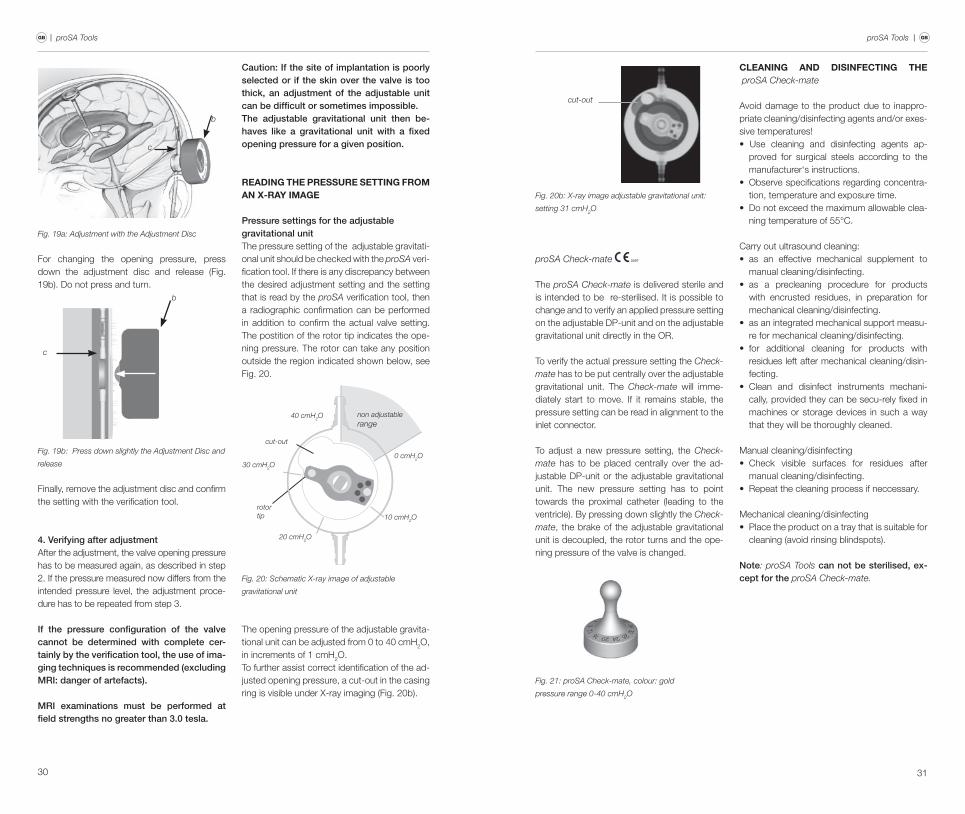
readIng the Pressure settIng from an X-ray Image
Pressure settings for the adjustable gravitational unitThe pressure setting of the adjustable gravitati-onal unit should be checked with the proSA veri-fication tool. If there is any discrepancy between the desired adjustment setting and the setting that is read by the proSA verification tool, then a radiographic confirmation can be performed in addition to confirm the actual valve setting. The postition of the rotor tip indicates the ope-ning pressure. The rotor can take any position outside the region indicated shown below, see fig. 20.
Fig. 20: Schematic X-ray image of adjustable
gravitational unit
rotortip
cut-out
30 cmH2O
40 cmH2O
20 cmH2O
10 cmH2O
0 cmH2O
non adjustable range
The opening pressure of the adjustable gravita-tional unit can be adjusted from 0 to 40 cmh2O, in increments of 1 cmh2O.To further assist correct identification of the ad-justed opening pressure, a cut-out in the casing ring is visible under X-ray imaging (fig. 20b).
cut-out
Fig. 20b: X-ray image adjustable gravitational unit:
setting 31 cmH2O
proSA Check-mate 0297
The proSA Check-mate is delivered sterile and is intended to be re-sterilised. It is possible to change and to verify an applied pressure setting on the adjustable dP-unit and on the adjustable gravitational unit directly in the Or.
To verify the actual pressure setting the Check-mate has to be put centrally over the adjustable gravitational unit. The Check-mate will imme-diately start to move. If it remains stable, the pressure setting can be read in alignment to the inlet connector.
To adjust a new pressure setting, the Check-mate has to be placed centrally over the ad-justable dP-unit or the adjustable gravitational unit. The new pressure setting has to point towards the proximal catheter (leading to the ventricle). By pressing down slightly the Check-mate, the brake of the adjustable gravitational unit is decoupled, the rotor turns and the ope-ning pressure of the valve is changed.
Fig. 21: proSA Check-mate, colour: gold
pressure range 0-40 cmH2O
cleanIng and dIsInfectIng the proSA Check-mate
Avoid damage to the product due to inappro-priate cleaning/disinfecting agents and/or exes-sive temperatures!• Use cleaning and disinfecting agents ap-
proved for surgical steels according to the manufacturer‘s instructions.
• Observe specifications regarding concentra-tion, temperature and exposure time.
• Do not exceed the maximum allowable clea-ning temperature of 55°c.
carry out ultrasound cleaning: • as an effective mechanical supplement to
manual cleaning/disinfecting.• as a precleaning procedure for products
with encrusted residues, in preparation for mechanical cleaning/disinfecting.
• as an integrated mechanical support measu-re for mechanical cleaning/disinfecting.
• for additional cleaning for products with residues left after mechanical cleaning/disin-fecting.
• Clean and disinfect instruments mechani-cally, provided they can be secu-rely fixed in machines or storage devices in such a way that they will be thoroughly cleaned.
manual cleaning/disinfecting• Check visible surfaces for residues after
manual cleaning/disinfecting.• Repeat the cleaning process if neccessary.
mechanical cleaning/disinfecting• Place the product on a tray that is suitable for
cleaning (avoid rinsing blindspots).
Note: proSA Tools can not be sterilised, ex-cept for the proSA Check-mate.

32
| proSA ToolsGB
recommendatIon for sterIlIsatIon of the proSA Check-mate
Sterilise the proSA Check-mate by steam sterilization (fractionated vacuum process) at 134°c and 5 minutes cycle time.
Notice: for use in the US, please check for further in-formation concerning sterilsation of the proSA Check-mate (www. aesculapusa.com)
cleanIng recommendatIon for proSA Tools whIch are not sterIlIsaBle
Attention: proSA Tools are made from ther-mal unstable components which are affec-table by heat or humidity or chemical agres-sive substances.Do not steep the proSA Tools in liquids and keep the inside of the instruments dry!
remove surface pollution of the proSA Tools after the use immediately with alcohol based cleaners (more than 75% alc.) by a wiping pro-cedure.The time of impact should be more than 60 sec. and should be depending on the level of polluti-on. for final cleaning use a dry wipe. The following cleaning methods are not allowed for the cleaning of the proSA Tools (except proSA Check-mate): Irradiation, Ultrasonic, Sterilization, machine preparation, Inserting into liquids.
medIcal Products consultant
In compliance with the requirements of the european law mdd 93/42/eec, christoph miethke Gmbh & co.kG names medical pro-duct consultants as the individuals to be addressed with all queries concerning the pro-ducts:
dipl.-Ing. christoph miethke dipl.-Ing. roland Schulz
christoph miethke Gmbh & co. kGUlanenweg 2d-14469 PotsdamPhone: +49(0) 7000 6438453 orPhone: +49(0) 331 620 83 0fax: +49(0) 331 620 83 40e-mail: [email protected]
Please address any enquiries to:AeScUlAP AG Am Aesculap Platzd-78532 TuttlingenPhone: +49 (0) 7461 95 0fax: +49 (0) 7461 95-26 00e-mail: [email protected]
Service address in the USAeScUlAP Inc.Attn. AeScUlAP Technical Services615 lambert Pointe roadhazelwood, mO, 63042AeScUlAP repair hotlinePhone: +1 (800) 214-3392fax: +1 (314) 895-4420
distributor in the US/ contact in canadaAeScUlAP Inc.3773 corporate Parkwaycenter valley, PA 18034Phone: +1-800-282-9000www.aesculapusa.com
general InformatIon
Manufacturer Christoph Miethke GmbH & Co. KG
Product name proSA Tools
Intended use Treatment of Hydrocephalus
Store in a clean, dry place

TA013339 GBA73 02 0513
ce-kennzeichnung gemäß richtlinie 93/42/ewGce marking according to directive 93/42/eeclabel ce conforme à la directive 93/42/ceeIdentificatión ce en conformidad con la directriz 93/42/ceemarchio ce conforme alla direttiva 93/42/cee
Technische Änderungen vorbehaltenTechnical alterations reservedSous réserve de modifications techniquesSujeto a modificationes técnicascon riserva di modifiche tecniche
manufacturer acc. mdd 93/42/eec:
CHRISTOPH MIETHKE GMBH & CO. KG
christoph miethke Gmbh & co. kG | Ulanenweg 2 | 14469 Potsdam | GermanyPhone +49 (0) 331 62 083-0 | fax +49 (0) 331 62 083-40 | www.miethke.com
distributed by:
Aesculap AG | Am Aesculap-Platz | 78532 Tuttlingen | GermanyPhone +49 (0) 7461 95-0 | Fax +49 (0) 74 61 95-26 00 | www.aesculap.com
Aesculap - a B. Braun company
0297