prosthetics and orthotics international · the alignment jigs ... technical note — an angular...
TRANSCRIPT
The Journal of the International Society for Prosthetics and Orthotics
Prosthetics and Orthotics International
December 1990, Vol. 14, No. 3

OTTO BOCK Modular Knee with Hydraulic Swing Phase Control
Performance of the OTTO ity Modular Prosthesis is tion of this new hydraulic knee. With the integration of a miniature I lower limb action is smoothed i natural gait. Flexion and extension are independently adjustable. Two plastic caps protect the with the front cap also serving pearaπce during flexion. This knee is recommended lor amputees who are less vigorous. 3R43 OTTO BOCK Modular -Stainless Steel- with Hyd(a 3R44 ditto -Titanium- with
ORTHOPÄDISCHE INDUSTRIE MM*44)o
BOCK Lower Extrem-enhánced by the addi-
sv>jing phase control
hydraulic unit, resulting in a more
hydraulic cylinder to enhance ap-
Knee Joint ulic Cylinder
(Hydraulic Cylinder
1ndustfit straße P.O. Box 1260 D - 3 4 0 É 0UDERSTADT Telephon (05527) 84β-0 Telefax (05527) 72330 Telex 9 35912
10.1990
Prosthetics and Orthotics International
Co-editors: JOHN HUGHES (Scientific) NORMAN A . JACOBS (Scientific)
RONALD G. DONOVAN (Production)
Editorial Board: VALMA ANGLISS PER CHRISTIANSEN
RONALD G. DONOVAN
JOHN HUGHES
NORMAN A . JACOBS
THAMRONGRAT KEOKARN
JEAN VAUCHER
Prosthetics and Orthotics International is published three times yearly by the International Society for Prosthetics and Orthotics (ISPO), Borgervaenget 5,2100 Copenhagen 0 , Denmark, (Tel. (31) 20 72 60). Subscription rate is £50 per annum, single numbers £18. The journal is provided free to Members of ISPO. Remittances should be made payable to ISPO.
Editorial correspondence, advertisement bookings and enquiries should be directed to Prosthetics and Orthotics International, National Centre for Training and Education in Prosthetics and Orthotics, University of Strathclyde, Curran Building, 131 St. James' Road, Glasgow G4 0LS, Scotland (Tel. 041-552 4049).
ISSN 0309-3646
Produced by the National Centre for Training and Education in Prosthetics and Orthotics, University of Strathclyde, Glasgow
Printed by David J. Clark Limited, Glasgow
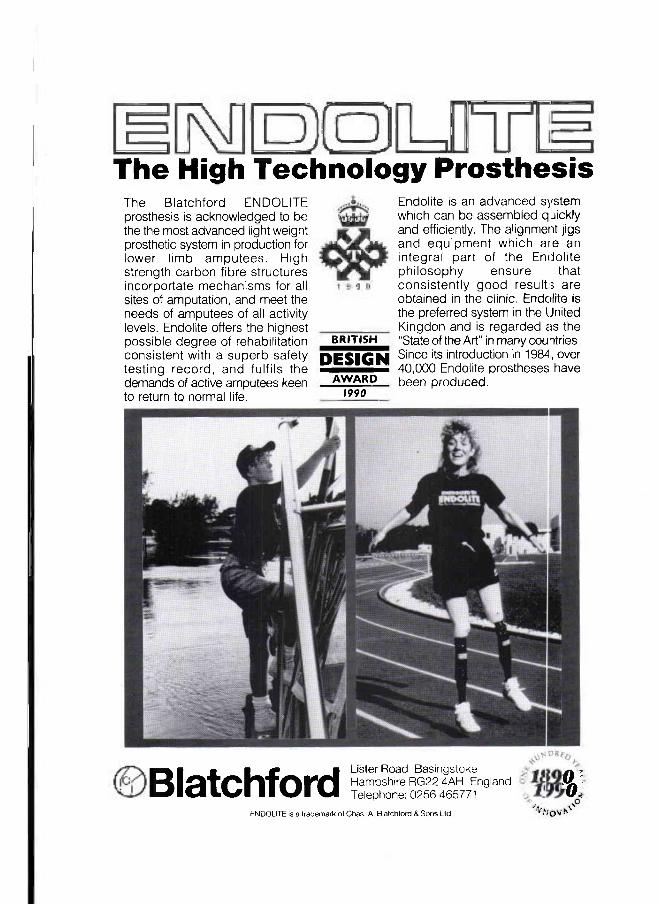
The High Technology Prosthesis The Blatchford ENDOLITE prosthesis is acknowledged to be the the most advanced light weight prosthetic system in production for lower limb amputees. High strength carbon fibre structures incorportate mechanisms for all sites of amputation, and meet the needs of amputees of all activity levels. Endolite offers the highest possible degree of rehabilitation consistent with a superb safety testing record, and fulfils the demands of active amputees keen to return to normal life.
B R I T I S H
DESIGN ^ A W A R D ~
1990
Endolite is an advanced system which can be assembled qjickly and efficiently. The alignment jigs and equipment which aie an integral part of the Endolite philosophy ensure that consistently good result:; are obtained in the clinic. Endolite is the preferred system in the United Kingdon and is regarded as the "State of the Art" in many countries. Since its introduction in 1984, over 40,000 Endolite prostheses have been produced.
Blatchford Lister Road Basingstoke Hampshire RG22 4AH England Telephone: 0256 465771
ENDOLITE is a trademark of Chas, A Blatchford & Sons Ltd
ft1
0
December 1990, Vol. 14, No. 3
Contents
Editorial 99
Georg Hohmann Medal 102
Performance of three walking orthoses for the paralysed: a case study using gait analysis 103 R. J. JEFFERSON and M. W. WHITTLE
The Edinburgh-ORLAU prosthetic system to provide reciprocal locomotion in children 111 and adults with complete transverse lower limb deficiency
C. B . MEADOWS, J. STALLARD, D. WRIGHT, L. GORDON, R. E. MAJOR and N. JONES
Stiffness and hysteresis properties of some prosthetic feet 117 H. W. L. VAN JAARSVELD, H. J. GROOTENBOER, J. DEVRIES and H. F. J. M. KOOPMAN
Analysis of the swing phase dynamics and muscular effort of the above-knee amputee for 125 varying prosthetic shank loads
S. A. HALE
An evaluation of computer aided design of below-knee prosthetic sockets 136 A. K. TOPPER and G. R. FERNIE
Technical note — an angular alignment measurement device for prosthetic fitting 143 J. E. SANDERS, C. H. DALY, D . A. BOONE and T . F. DONALDSON
Letter to the Editor 145
International Newsletter 146
Blatchford and Forchheimer Prizes 148
Calendar of events 149
ISPO Sponsoring Members 1990 154
ISPO Seminar on Clinical Biomechanics of the Foot and Shoe 155
ISPO Seventh World Congress 156
Index to Volume 14 159
iii
Prosthetics and Orthotics International, 1990, 14
ISPO Elected Members of Executive Board: W. H. Eisma (President) Netherlands M. Stills (President Elect) U S A S. Heim (Vice President) FRG A. Jernberger (Vice President) Sweden V. Angliss Australia P. Christiansen Denmark T. Keokarn Thailand J. Vaucher Switzerland J. Hughes (Past President) UK E. Lyquist (Past President) Denmark G. Murdoch (Past President) UK J. Steen Jensen (Hon. Treasurer) Denmark N. A . Jacobs (Hon. Secretary) UK Standing Committee Chairmen and Task Officers J. Kjølbye (Finance) Denmark J. Hughes (Protocol) UK M. Stills (Congress and Membership) U S A J. Edelstein (International Newsletterand
Journal Promotion ) U S A H. C. Thyregod (Professional Register) Denmark H. J. B. Day (Limb Deficient Child) UK V. Angliss (Publications) Australia S. Heim/J. Hughcs/G. Murdoch (Education) FRG/UK/UK G. Murdoch (Amputation Surgery) UK Consultants to Executive Board H. C. Chadderton (Consumer) Canada R. Henze (IVO) FRG J. Van Rolleghem ( INTERBOR) Belgium J. N. Wilson (WOC) UK International Consultants to Executive Board P. Kapuma Africa J. Craig Central America C. Marincek Eastern Europe S. Sawamura Asia A . P. Kuzhekin USSR Chairmen of National Member Societies Australia A . van der Borch Austria W . O t t Belgium M. Stehman Canada G. Martel China Zhongzhe Wu Denmark P. Christiansen FRG G. Fitzlaff Hong Kong K. Y. Lee India M. K. Goel Israel M. Azaria Japan S. Sawamura Korea Yong-Pal Ahn Netherlands J. C. L. van der Meer New Zealand A . W. Beasley Norway G. Veres Pakistan N. M. Akhtar Sweden A.Jernberger Switzerland J. Vaucher UK C. Peacock U S A M. Le Blanc Past Presidents K.Jansen(1974-1977) Denmark G. Murdoch (1977-1980) UK A. Staros(1980-1982) U S A E. Lyquist (1982-1983) Denmark E. G. Marquardt (1983-1986) FRG J. Hughes (1986-1989) UK Secretary Aase Larsson Denmark
İv
Prosthetics and Orthotics International, 1990, 14, 99—101
Editorial
In the summer of 1963, a brilliant summer in Copenhagen, three important events in our field took place in successive weeks. The first was the World Congress of the International Society for Rehabilitation of the Disabled (ISRD), now Rehabilitation International (RI), the second, the meeting of the World Federation and the third, the International Instructional Course of the International Committee on Prosthetics and Orthotics (ICPO), the precursor of ISPO. Important though the first two events were for our patients neither had the impact of the third. This was principally because of a lecture presented by, at that time, a largely unknown Polish surgeon, Marion Weiss. He was a striking figure in his black cloak and wide-brimmed floppy hat but his lecture was even more striking as it introduced the notion of Immediate Postoperative (or Post-surgical) Fitting (IPOF or IPSF) and early walking. He was an orthopaedic surgeon working in the field of Rehabilitation in Konstancin where he followed the ethics of his teacher, Dega. As such he in fact introd uced a total package of the fundamental elements of the rehabilitation of the amputee including the surgery. Marion never claimed that his ideas were entirely new and paid due tribute to both Berlemont of Berck-Plage with regard to IPOF and to Dederich of Bonn with respect to the surgery.
Fortunately A. Bennett Wilson Jr. then working as Director for the Committee for Prosthetic Research and Development (CPRD) and Tony Staros as Chief of the Veterans Administration Prosthetic Centre (VAPC) recognized the significance of the event and once back home mobilized funds to send Ernest Burgess and Joe Traub to Poland, bring Marion Weiss to the US and set up research programmes principally in Seattle and Florida. From Marion Weiss' initiative and the actions just described stemmed a tremendous wave of interest in both surgery and prosthetics including IPOF. The effects were wide ranging and the stimulus given to prosthetists, surgeons and to many engineers and scientists formerly outside our field has seen many advances in patient care. Standards in level selection, amputation surgery, prosthetic fitting and rehabilitation within the concept of the clinic team produced lower levels of amputation and many more of the elderly being successfully returned to home and family.
Prosthetic research and development has continued and the prosthetists armed with new knowledge fitted the stumps presented to them and with improved surgical techniques they fitted more of them. It cannot be said that progress has been sustained over the years in the same way in surgery. As in many other situations if the surgeon does not perform amputation surgery often enough high standards of performance cannot be attained and, if already achieved, cannot be maintained. When funding for research groups dwindled so did the number of surgeons with a special interest in amputation. Very often the improved skills of the prosthetist "rescued" the patients from the worst of problems than can attend poor stump construction. A number of us in close contact with both surgery and prosthetics have been aware of this worsening situation for some time and discussed ways in which improvements could be made. At first sight the obvious solutions will include an increase in targeted instructional courses and persuading relevant authorities to ensure that surgeons in training are examined in amputation surgery in Board, Fellowship and equivalent examinations. It was felt however that our strategy required another dimension. Largely at the suggestion of A. Bennett Wilson Jr. it was decided to hold a "consensus" conference on which to base our efforts.
A "consensus" conference requires that a group of acknowledged experts in the field in question are brought together but only after a rigorous review of the literature. In our case the subject area is amputation surgery and related prosthetics — as always in ISPO within the concept of the clinic team. A decision was made to hold the conference in the National Centre for Training and Education in Prosthetics and Orthotics (NCTEPO) in the University of Strathclyde, Glasgow, Scotland not least because of its Information Centre and in particular RECAL — a computerized literature retrieval system. It also happened that for the year of 1990 Glasgow was the European City of Culture but more of that anon. Our Immediate Past President, Professor John Hughes, Director of NCTEPO was our host and the meeting was also attended by the President, Professor Willem Eisma and the President-Elect, Melvin Stills.
Once selected those chosen to present contributions at the different levels of amputation were grouped in pairs — a surgeon and a prosthetist — to review the literature covering the past 20 years along with highly prized contributions from the past. In all over 1000 publications were scrutinized. Each team was asked to
100 Editorial
classify their allotment of publications according to its worth as outlined here: (1) usefulness as demonstrated by a randomized controlled trial, (2) usefulness as demonstrated by a non-randomized controlled trial, (3) deemed to be contra-indicated on the basis of scientific evidence, (4) seen to be common practise but lacking scientific evidence, (5) not in common practise and without scientific evidence, (6) simple anecdotal.
Each of the selected speakers was asked to deliver a judgement on the available literature. It was also seen as appropriate to comment on such aspects as level selection, the treatment of bone, muscle, nerve, fascia and skin, the detail of skin closure, immediate post-operative stump environment and early prosthetic management. It was assumed that distinctions would be made regarding causal pathology e.g. trauma, disease, malformation. The prosthetist speakers were given a similar but complementary task.
The work of the conference was based on what has now become an ISPO Workshop framework with each presentation followed in due course by plenary discussion, syndicate discussions and a further plenary discussion. The participants shared the tasks of acting as chairmen or rapporteurs at all ssssions.
I emphasize to the membership at large the magnitude of the task given to each of the researcher/ presenters. They responded magnificently and our congratulations are due to them for the quality of their research and presentations. The care taken by them in their preparation clearly stimulated the other participants in discussions. All points of controversy were hotly debated but respect was shown to all whether they were "up and coming" or "elder statesmen". The whole group are to be congratulated on one other aspect of the weeks work, namely, time-keeping. It was a very good self-disciplined performance which enabled the work to proceed smoothly.
The help provided by the staff of NCTEPO was substantial and significant. In addition to assembling the literature held in the RECAL database under each subject heading other databases were recruited when required to make the 1000 odd collection of papers. All were copied and distributed as appropriate and during the workshop itself copies of publications not included were produced on demjind to help the participants elucidate particular points.
As the workshop got under way the plenary and syndicate sessions began to spawn paper (the reports of the sessions) in quantity. Each report had to be produced in very short order, scrutinized, typed and then copied — a production line effort performed with expertise and good humour.
A moderating group met each lunchtime and after discussion listed the questions to be ac dressed by the next set of syndicates. At the same time the members for each syndicate were selected and a chairman and rapporteur appointed.
The costs of the Workshop were largely borne by the Society but substantial sponsorship was provided by the U.S. Manufacturing Co., Otto Bock, North Sea Plastics and L.I.C. A number of individuals made significant contributions by finding their own sponsorship. In addition the NCTEPO, the; University of Strathclyde and the City of Glasgow made many contributions to the social events which accompanied the workshop.
The City of Glasgow was the European City of Culture for 1990 and as a result there were many special events and exhibits as well as its celebrated museums for the accompanying persons to visit.
Marion Weiss would have been in his element at the workshop. He loved the art of surgery, revered the science to support it, the tussle of debate, the company of friends, good food, wine and music. Most of all he would have been pleased with the outcome.
By the time this editorial is in your hands the Co-Chairmen G. Murdoch and A. Bennett Wilson Jr. and our Honorary Secretary, Norman A. Jacobs, hope that the report of the meeting will have been sent to the participants and returned to us with as few amendments as possible! The final outcome will De a document wholly based on the report of the workshop. The publication will be used as the main body of knowledge supporting a series of Instructional Courses to be held in the main continents of the world over the next three or four years. It will prove to be much more than a 'cookbook' but assured guidelines for any surgeon undertaking amputation surgery.
It will not be a tablet of stone but in certain areas it will be difficult to fault the advices. In transiliac and transpelvic amputation the advices are clear and received almost unanimous support. In level determination there are solid guidelines to follow whether you have limited resources or a sophisticated
Editorial 1 0 1
laboratory to hand. At above-knee (transfemoral) level of amputation there was little in the way of scientific studies to guide us but the consensus was strongly for a myodesis. How pleased Marion Weiss would have been to know that! Certainly those who advocated the technique over twenty years ago were much in agreement. At both through knee and specifically knee disarticulation there was considerable discussion but primarily about points of detail. At the below-knee level of amputation a consensus was reached and the surgeon left with three options for flap design. That which remained unresolved related mainly to the treatment of the fibula. Amputations at the ankle received considerable attention much of the difficulty concerning terminology and the minutia of bone section (the debate seemed to finally concentrate on 2 or 3 millimetres of difference). Partial foot amputations have received renewed interest in recent years presumably because of the desire to achieve more distal levels of amputations, improved techniques in tissue transference, external fixation and the emergence of new materials. The various facets were explored in detail but a distilled consensus is difficult to identify.
Special attention was paid to the role of diabetes in amputation and clear guidelines are given regarding the regimen to follow in the management of the diabetic foot. The alternative approach to amputation viz. "auto-amputation" was explored in much detail; there is, as yet, no consensus.
The place of amputation in trauma was given close attention with opinions derived from long experience in areas of urban guerilla warfare, open warfare and the developing world. With regard to the latter the important cultural aspects of both surgery and prosthetics was described. The special considerations with regard to the growth period were debated with little divergence of opinion.
Stump environment was seen to be of great significance especially in vascular disease and diabetes. The subject led to much controversy and while the options remain the advantages and disadvantages of the different techniques were identified.
The initial conception of the workshop did not include the upper limb in the programme but pressure from the consumer persuaded us to include the subject. The division of opinion regarding levels of amputation is clearly still there — preserve all length or seek optimum length with regard to the prosthetic hardware available.
Finally there was a display of the work of ISPO within the International Standards Organisation in Technical Committee 168, (Working Groups I and II) in the field of terminology with respect to descriptors for amputation stumps. This received widespread approval allied to the hope that these descriptors will be used in all relevant publications.
As in ISPO workshops the participants represented all aspects of the rehabilitation of the amputee. Thus the professions of engineering, medical rehabilitation, orthotics and physical therapy all had a say in the proceedings. To keep us on the straight and narrow we were honoured to have a physicist with an international standing in service and research in vascular surgery and amputation investigation. Of the surgeons present two were vascular surgeons both very active in vascular surgery and amputation and with fine records in research and publication. Last but not least and complementary to the objective of improved surgical performance were the prosthetists. In addition to displaying the level of skills in socket design, alignment, functional performance and cosmesis they outlined the limits of their craft and science. As stated before they have been able to disguise and sometimes compensate for errors in surgical technique but they admitted that even they cannot perform miracles! They made clear statements as to what they looked for and what they abhorred in amputation stumps. Their understanding of biomechanics and the basic desiderata of prosthetic design had a direct bearing on the surgical discussions e.g. on transfemoral amputation. There could not have been a better illustration of the value of teamwork than the intermingling of the disciplines and the quality of debate that we saw at this workshop.
The last session was devoted to developing a set of recommendations for action by ISPO wherever it can bring its influence to bear particularly with funding authorities.
I believe A. Bennett Wilson Jr. and I hope our President, Professor Willem Eisma and the Vice-President, Melvin Stills will join me in congratulating the participants on the quality of their presentations and discussions and their disciplined approach to the workshop. The results of this workshop and subsequent courses will have a significant effect on the treatment of the amputee.
G. Murdoch Co-Chairman Consensus Conference on Amputation Surgery

Prosthetics and Orthotics International, 1990, 14, 102
GEORG HOHMANN MEDAL
The German Orthopaedic and Traumatologic Association has honoured at its General Assembly on October 10, 1990 our friend and colleague André Bähler with the Georg Hohmann Medal. This medal is given every year to a person with special merits in prosthetics and orthotics. Amongst the merits of André Bähler, mentioned in the laudatio by the President of the Association, Professor A. Schrieber, Zurich, were not only innovations in orthotics, but also his contributions in joint replacements and, last but not least, his professional activities as President of INTERBOR and Vice-President of ISPO.
We are sure that the membership will join with us in congratulating him and wishing him well in the continuation of his good work.
102
Prosthetics and Orthotics International, 1990, 14, 103—110
Performance of three walking orthoses for the paralysed: a case study using gait analysis
R. J. JEFFERSON and M. W. WHITTLE
Oxford Orthopaedic Engineering Centre, Nuffield Orthopaedic Centre, Headington, Oxford, UK
Abstract Three types of walking orthosis are currently available to enable paralysed people to achieve reciprocal gait. This case study assesses the performance in walking of one patient who was proficient in the use of all three devices. The results of a biomechanical analysis are presented in which comparisons are made between the orthoses in terms of general gait parameters and movement of the lower limbs and pelvis.
Introduction In recent years a considerable amount of time,
effort and money has been directed towards permitting paralysed people to walk again using reciprocal gait. Stallard et al. (1989) noted that of the three approaches currently under development (mechanical orthoses, functional electrical stimulation, and hybrid devices which combine the first two alternatives) only the first, using purely mechanical orthoses, is clinically viable at the present time, and even this has its limitations. However, continuing research and corresponding advances in medical technology mean that the future may hold many exciting new developments, with corresponding benefits to the paraplegic person.
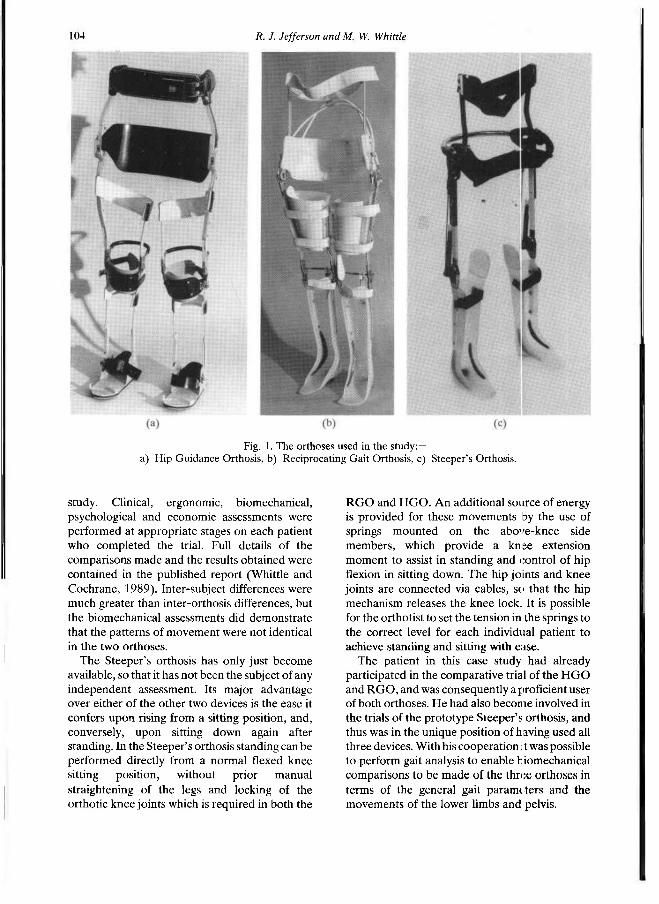
During the last few years two designs of walking orthosis have emerged as practical systems. The hip guidance orthosis (HGO) or "ParaWalker" (Fig. 1a) was developed by Gordon Rose and his colleagues at the Orthotic Research and Locomotor Assessment Unit, Oswestry, England
(Rose, 1979). The reciprocating gait orthosis or RGO (Fig. 1b) was developed by Roy Douglas with his colleagues at Louisiana State University (Douglas et al., 1983). More recently a third design, a development of the RGO system, has emerged from Hugh Steeper Ltd, London, and is henceforward referred to as the Steeper's orthosis (Fig. 1c).
As far as locomotion is concerned, the general principles of all three orthoses are similar. The body is braced from the mid-trunk to the feet, with knees and ankles immobilised. The hips are allowed to flex and extend, but are prevented from moving into adduction when the leg is lifted off the ground. Walking is achieved by pulling the trunk forward, using crutches or rollator, then tipping the pelvis so that the trailing leg is lifted clear of the ground, thus allowing it to move forward and take a step. The hip joints on the HGO are free to flex and extend between stops, whereas on the RGO there are twin cables linking the two sides so that extension on one side causes flexion on the other. On the Steeper's orthosis the hip mechanism is a modified version of that in the RGO, but using only a single cable, encased in a steel tube. The use of only one cable should have the effect of reducing friction.
In response to the pressure from patients wishing to be provided with walking orthoses, following considerable publicity given by the media to one particular paraplegic, the Department of Health and Social Security in the United Kingdom commissioned an extensive, comparative trial of the HGO and RGO which spanned almost two years and was carried out at the Nuffield Orthopaedic Centre, Oxford. Some 22 patients were given the opportunity to use each orthosis for a period of 4 months in a crossover
All correspondence to be addressed to Dr. R. R. J. Jefferson, Oxford Orthopaedic Engineering Centre, Nuffield Orthopaedic Centre, Windmill Road, Headington, Oxford OX3 7LD, U K
103
104 R. J. Jefferson and M. W. Whittle
study. Clinical, ergonomic, biomechanical, psychological and economic assessments were performed at appropriate stages on each patient who completed the trial. Full details of the comparisons made and the results obtained were contained in the published report (Whittle and Cochrane, 1989). Inter-subject differences were much greater than inter-orthosis differences, but the biomechanical assessments did demonstrate that the patterns of movement were not identical in the two orthoses.
The Steeper's orthosis has only just become available, so that it has not been the subject of any independent assessment. Its major advantage over either of the other two devices is the ease it confers upon rising from a sitting position, and, conversely, upon sitting down again after standing. In the Steeper's orthosis standing can be performed directly from a normal flexed knee sitting position, without prior manual straightening of the legs and locking of the orthotic knee joints which is required in both the
RGO and HGO. An additional source of energy is provided for these movements by the use of springs mounted on the above-knee side members, which provide a knee extension moment to assist in standing and control of hip flexion in sitting down. The hip joints and knee joints are connected via cables, so that the hip mechanism releases the knee lock. It is possible for the orthotist to set the tension in the springs to the correct level for each individual patient to achieve standing and sitting with ease.
The patient in this case study had already participated in the comparative trial of the HGO and RGO, and was consequently a proficient user of both orthoses. He had also become involved in the trials of the prototype Steeper's orthosis, and thus was in the unique position of having used all three devices. With his cooperation it was possible to perform gait analysis to enable biomechanical comparisons to be made of the three orthoses in terms of the general gait parameters and the movements of the lower limbs and pelvis.
Fig. 1. The orthoses used in the study:— a) Hip Guidance Orthosis, b) Reciprocating Gait Orthosis, c) Steeper's Orthosis.
Walking orthoses for the paralysed 105
Methods Subject
The subject for the case study was a 33-year-old man (height 1.76m, weight 72kg) with complete motor and sensory paraplegia below T5 segmental level as a result of a motorcycle accident five years previously. He was otherwise fit, his only regular medication being Baclofen (20mg three times daily) to control extensor spasticity present in both his legs. After his accident, he had been fitted with Hip Knee Ankle Foot Orthoses, and although he could stand in these with the aid of crutches, he was unable to walk with them. He first attended the Nuffield Orthopaedic Centre in November 1986, when he was selected to participate in the comparative trial of the HGO and RGO. His determination to succeed led to his achieving a considerable degree of proficiency in both orthoses. Ultimately he chose to keep the RGO.
Subsequent to this he became involved in the manufacturer's trial of the prototype Steeper's orthosis, and consented to attend the Oxford Orthopaedic Engineering Centre once again so that biomechanical assessments of his gait wearing all three devices could be performed. Assessments
Two methods of biomechanical assessments were used — conventional videotape and the Vicon motion analysis system. The former was used to determine the general gait parameters (cadence, stridelength and velocity) by means of a stopwatch and markers at known positions on the floor.
The Vicon television/force platform/ computer system was used for the full biomechanical assessment. Retroflective markers were attached to whichever orthosis was being worn, at the levels of mid-foot, ankle, knee, hip, and front and back of the trunk support. These
showed up as bright spots in the field of view of four television cameras, when illuminated by strobes mounted close to the lens of each camera. The cameras were interfaced to a PDP 11/23 minicomputer. The system was calibrated to give the three-dimensional location of each of the reflective markers at 20ms intervals, to an accuracy of 3-4mm in all three directions (Whittle, 1982 and 1986). Data were recorded during two walks at free speed with each orthosis. The subject first used the RGO with a rollator, followed by the Steeper's orthosis with the same rollator, and, finally, the HGO with crutches. He used his normal walking aid, whether rollator (RGO and Steeper's orthosis) or crutches (HGO). Unfortunately, it was not possible to assess the proportion of force passing through the walking aid due to problems with instrumenting the rollator. In addition, no attempt was made to obtain valid force platform data as this would have involved considerably greater problems for the patient. The kinematic data were subsequently analysed to determine the detailed linear and angular movements of the braced lower limbs and pelvis. The processed data from the two walks with each orthosis were combined to give average values of the relevant parameters. The general gait parameters were calculated and compared with those obtained from the videotape measurements. Other important biomechanical parameters studied included the range of motion of hip joints in both the flexion/extension and adduction/abduction axes, and the movements of the pelvis both up and down and side to side.
Results General gait parameters
Table 1 lists the values of these parameters for each of the orthoses used. Measurements were made both from the videotape and from the
Table 1. General gait parameters using all three orthoses.
106 R. J. Jefferson and M. W. Whittle
Vicon data. The normal ranges are derived from young men measured in our laboratory (Kirtley et al., 1985). Differences are small and, despite acclimatisation time, are possibly attributable to the patient's greater degree of familiarity with the RGO and Steeper's orthosis, both of which he used regularly at home.
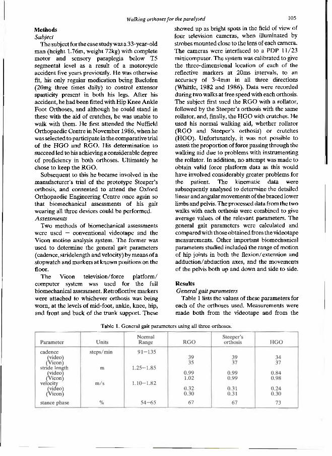
Pattern of Movement Figure 2 (a, b, c) shows a sagittal plane
representation of the position of the right leg and pelvis plotted at 60 ms intervals during a single gait cycle from heelstrike to heelstrike in each orthosis. Scaling factors are constant. Features of note are:—
i) a similar stride length in all three cases, ii) a smaller range of pelvic motion and a
different mean anteroposterior tilt in the HGO,
iii) a more jerky pattern of movement in the RGO and Steeper's orthosis, appearing as widely spread lines when the legs are moving faster, and more crowded lines when the movement slows down.
In the transverse plane the pelvis twists forwards and backwards about the vertical axis in the HGO, whereas in the RGO and Steeper's orthosis it remains fairly straight throughout the cycle.
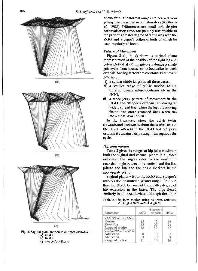
Hip joint motion Table 2 gives the ranges of hip joint motion in
both the sagittal and coronal planes in all three orthoses. The angles refer to the maximum recorded angle between the vertical and the line joining the hip and the ankle markers in the appropriate plane.
Sagittal plane:— Both the RGO and Steeper's orthosis demonstrated a greater range of motion than the HGO, because of the smaller degree of hip extension in the latter. The hips flexed similarly in all three devices, although flexion in
Fig. 2. Sagittal plane motion in all three orthoses:— a) HGO, b) R G O , c) Steeper's orthosis.
Table 2. Hip joint motion using all three orthoses. All angles measured in degrees.
H diking orthoses for the paralysed 107
the Steeper's orthosis was slightly less than in the RGO, with a corresponding increase in extension to maintain the overall similarity of range. In all three orthoses the foot did not contact the ground until the hip had reached full flexion and started to extend again. In the RGO and Steeper's orthosis there was a hesitation after heelstrike, at the time when the rollator was moved forwards, whereas the pattern in the HGO was more regularly sinusoidal.
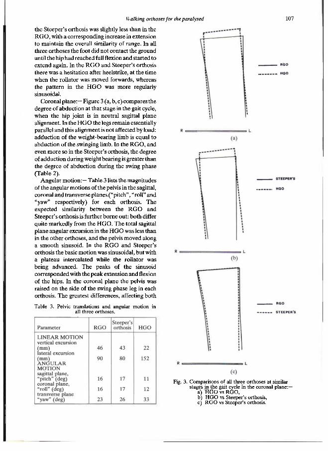
Coronal plane: — Figure 3 (a, b, c) compares the degree of abduction at that stage in the gait cycle, when the hip joint is in neutral sagittal plane alignment. In the HGO the legs remain essentially parallel and this alignment is not affected by load: adduction of the weight-bearing limb is equal to abduction of the swinging limb. In the RGO, and even more so in the Steeper's orthosis, the degree of adduction during weight bearing is greater than the degree of abduction during the swing phase (Table 2).
Angular motion:— Table 3 lists the magnitudes of the angular motions of the pelvis in the sagittal, coronal and transverse planes ("pitch", "roll" and "yaw" respectively) for each orthosis. The expected similarity between the RGO and Steeper's orthosis is further borne out: both differ quite markedly from the HGO. The total sagittal plane angular excursion in the HGO was less than in the other orthoses, and the pelvis moved along a smooth sinusoid. In the RGO and Steeper's orthosis the basic motion was sinusoidal, but with a plateau intercalated while the rollator was being advanced. The peaks of the sinusoid corresponded with the peak extension and flexion of the hips. In the coronal plane the pelvis was raised on the side of the swing phase leg in each orthosis. The greatest differences, affecting both
Table 3. Pelvic translations and angular motion in all three orthoses.
Fig. 3 . Comparisons of all three orthoses at similar stages in the gait cycle in the coronal plane:—
a) H G O vs R G O , b) H G O vs Steeper's orthosis, c) R G O vs Steeper's orthosis.
the magnitude and phasing of the movement, were observed in the transverse plane. In the HGO the twisting of the pelvis from side to side in a sinusoidal pattern had a much greater amplitude than in either the RGO or Steeper's orthosis. In these devices, higher frequency oscillations were superimposed on the basic sinusoid, once again due to the pattern of movement with the rollator; both sides of the pelvis tended to be advanced together.
Pelvic translations:— The vertical excursion of the centre of the pelvis in the HGO was approximately half its observed value in the other two orthoses. It also followed a more gently undulating sinusoidal path. Peak values in all three orthoses were attained during the swing phase on each side. The centre of the pelvis had a larger lateral excursion in the HGO and its locus was almost a pure sinusoid, compared with a more complex pattern in the RGO and Steeper's orthosis. In all three cases the maximum excursion was away from each leg during its swing phase.
Pelvic velocity:— The velocity in the direction of progression attained a maximum in the middle of the swing phase and a minimum just after heelstrike, irrespective of device. However, the range of velocity variation did differ between orthoses. The HGO showed a variation in forward velocity between 0.15m/s and 0.45m/s, compared with a range of 0.05m/s to 0.63m/s in the RGO and of 0.01m/s to 0.59m/s in the Steeper's orthosis. These results give further evidence of a stop-start pattern in the RGO and Steeper's orthosis; in the latter device there is an instant in the cycle when the pelvis is virtually stationary.
Discussion It could be argued, with some justification, that
the comparisons in this paper are more accurately between the different systems (orthosis plus walking aid) than between the devices themselves. The walking aids were those specified in the training directions for each orthosis, and were, therefore, those the patient would be expected to use with the particular device. Familiarity with the system should produce a better gait, and for the purposes of this study was thus allowed to override the scientific advantages of restricting the patient to using the same walking aid with each system. It has not been possible in the present study to ascertain the significance of the different aids, though the small differences
observed in the general gait parameters (Table 1) would suggest that the effect on the speed of walking may not be very great.
In the sagittal plane the major differences in hip joint motion between the respective orthoses is the smaller degree of hip extension in the HGO. The increased pelvic rotation, however, neutralises any consequent difference in stride length. In the RGO and Steeper's Orthosis, the stride length is achieved almost entirely by the degree of flexion/extension at the hip joints. It is surprising that these two orthoses are so similar, as far as sagittal plane motion is concerned, since the reduction in friction from the use of a single cable in the Steeper's orthosis should permit an increased range of hip movement.
The observation that the hip abd action in the HGO is greater than that in either the: RGO or the Steeper's orthosis has important implications with regard to ground clearance during the swing phase. In the HGO it is easier to clear the ground without catching the swinging leg behind the stance leg. Whittle and Cochrane (1989) noted this as probably the most importam: mechanical difference between the HGO and RGO, and one which makes the HGO more suitable for use with crutches. The present case study further bears out this observation. The reason for the difference is undoubtedly the greater degree of flexibility of both the RGO and Steeper's orthosis, compared with the HGO. On examination, the Steeper's orthosis was found to be slightly more flexible than the RGO; this would explain the absence of abduction during the swing phase. In the Steeper's orthosis, ground clearance: is achieved almost entirely by elevation of the pelvis.
Thurston et al. (1981) measured the angular displacements of the pelvis in the sagittal, coronal and transverse planes in 22 normal subjects. The angular displacements in the present study differ markedly from their results in both magnitude and pattern. In all three orthoses, there is an increased 'roll' which may be associated with the compensations necessary to gain foot clearance in a stiff-legged gait (Saunders et al., 1953). The greater than normal "yaw" in the HGO is an exaggeration of the normal mechanism whereby pelvic twisting is used to increase the stride length. With the arms fixed by the crutches, the contraction of latissimus dorsi pulls the pelvis upwards and twists it forwards. This twisting movement continues into stance until after the toe-off on the opposite (swing) side, whereupon it
108 R. J. Jefferson andM. W. Whittle
is rapidly reversed to impart some acceleration to the swinging leg. In the RGO and Steeper's orthosis, the maximum forward twisting of the pelvis occurs at the time of the corresponding heelstrike.
The variations in the vertical excursion of the centre of the pelvis in the different devices can also be associated with the different patterns of movement observed. In the RGO and Steeper's orthosis, both sides of the pelvis tend to be advanced together, which will necessitate a greater elevation of the pelvis, achieved by pushing down on the rollator, to permit forward progression. It results in a more jerky movement.
The other notable difference between the RGO and the Steeper's orthosis is the variation of the velocity in the direction of progression. The motion is better sustained in the RGO than in the Stepper's orthosis, for which there is an instant in the gait cycle when the pelvis is momentarily stationary, giving an additional contribution to the jerky motion already observed. Neither of these devices, however, achieves the smoothness of the HGO.
On the basis of the smaller pelvic movement in the HGO, it would be expected that the energy cost of walking in this orthosis would be less than in either of the other two devices. In this case study, however, energy expenditure was not measured, since it is difficult to make accurate measurements, and the results of the comparative trial (Whittle and Cochrane, 1989) do not suggest that there is an important difference in energy consumption between the HGO and the RGO.
The study would have been enhanced by the addition of kinetic data, although considerable difficulties would be involved in its acquisition. The aim of the study was to measure the patient's natural gait in each orthosis using the recommended walking aid, without imposing any additional constraints. The relatively short step length would make it very difficult to acquire "clean" data, with one foot per force platform, and there is also a strong possibility of recording a mixture of contact by the foot and the walking aid. In addition, it is very undesirable that the patient should "aim" for the force platforms.
Conclusions Similar patterns and magnitudes of motion
were observed in both the RGO and the Steeper's orthosis. Important biomechanical differences were noted in:—
i) swing phase hip abduction and, therefore, in the way in which ground clearance was achieved,
ii) the variation of velocity in the direction of progression: the pelvis was momentarily stationary at a particular instant in the gait cycle in the Steeper's orthosis, contributing to a more jerky motion.
The major difference between the two, however, appeared not in the walking performance but in standing up and sitting down. The inclusion of a compression mechanism in the Steeper's orthosis made sitting and standing much easier, with corresponding advantages to the patient both socially and in terms of energy expenditure at the beginning and ending of a walk.
The HGO showed marked differences from the other two devices, viz:—
i) a smaller variation of forward velocity, and a greater smoothness of the fore- and aft-movements,
ii) the subject's legs remained essentially parallel in the coronal plane, giving better ground clearance,
iii) a smaller range of sagittal plane motion, the compensation for which is a greater degree of pelvic twisting.
In this study we have concentrated on objective measurements, to the exclusion of other important factors such as cosmesis and ease of donning and doffing, which significantly influence the choice of the individual patient. However, in order to improve the design and function of future devices, an understanding of the biomechanics of movement in those currently available is essential. This paper is offered as a step towards this goal.
R E F E R E N C E S
DOUGLAS, R . , LARSON, P . F . , D'AMBROSIA, R . , MCCALL, R . E . (1983) . The L S U reciprocation gait orthosis. Orthopedics 6, 8 3 4 - 8 3 8 .
K i r t l e y , C . , WHITTLE, M . W . , JEFFERSON, R . J. (1985). Influence of walking speed on gait parameters. J. Biomed. Eng. 7 , 2 8 2 - 2 8 8 .
ROSE, G . K . (1979) . The principles and practice of hip guidance articulations. Prosthet. Orthot. Int. 3 , 3 7 - 4 3 .
Walking orthoses for the paralysed 109

110 R. J. Jefferson and M. W. Whittle
SAUNDERS, J. B. DE M., INMAN, V. T., EBERHARDT, H. D. (1953) . The major determinants in normal and pathological gait. J. Bone Joint Surg. 3 5 A , 543—558.
STALLARD, J. , PATRICK, R . E . , MAJOR, R . E . (1989) . A review of the fundamental design problems of providing ambulation for paraplegic patients. Paraplegia 2 7 , 7 0 - 7 5 .
THURSTON, A . J. , WHITTLE, M . W . , STOKES, I. A , F . (1982) . Spinal and pelvic motion during walking — a new method of study. Eng. Med. 1 0 , 2 1 9 - 2 2 2 .
WHITTLE, M. W . (1982). Calibration and performance of a three-dimensional television system for kinematic analysis. J. Biomech. 1 5 , 185—196
WHITTLE, M. W . (1986). Dynamic assessment of knee joint function. Eng. Med. 1 5 , 71—75.
WHITTLE, M . W . , COCHRANE, G. M . (1989) . A comparative evaluation of the hip guidance orthosis (HGO) and the reciprocating gait orthosis (RGO). Health Equipment information No. 192: London, National Health Service Procurement Directorate.
Prosthetics and Orthotics International, 1990, 14, 111—116
The Edinburgh-ORLAU prosthetic system to provide reciprocal locomotion in children and adults
with complete transverse lower limb deficiency
C. B. MEADOWS, J. STALLARD*, D. WRIGHT, L. G O R D O N † , R. E. MAJOR*, and N. JONES*
Bioengineering Centre, Princess Margaret Rose Orthopaedic Hospital, Edinburgh, UK *Orthotic Research & Locomotor Assessment Unit, Robert Jones and Agnes Hunt Hospital, Oswestry, UK
†Physiotherapy Department, Royal Hospital for Sick Children, Edinburgh, UK
Abstract A novel prosthetic system to provide reciprocal locomotion in children and adults with complete transverse lower limb deficiency is described. This is based on the hip joints from the O R L A U Para Walker, a system with a proven record of success in the orthotic management of paraplegic patients. The fitting of the prototype system to an eight year old girl is described. This experience shows that the orthotic principles of the ParaWalker, which provides reciprocal locomotion for the paraplegic, is equally applicable to the prosthetic situation. Developments are therefore continuing to improve the design and to enable further fittings.
Introduction Walking for bilateral lower limb deficient
patients has long been considered an impracticality. One approach involved the use of twin linked pylons attached to a prosthetic socket, with the patient performing swing through gait using a rollator, though crutches may also theoretically be used. The problems of this style of walking are: very high energy consumption, fatiguing of the upper limbs, and an obviously abnormal walking pattern. A different approach is to use a swivel walking mechanism attached to the underside of the prosthetic socket (Hall, 1962; Speilrein, 1963; Klein, 1964; Lamb et al., 1970). Whilst this reduces energy consumption it is relatively slow and also produces an exceptionally abnormal style of walking.
Additionally it is limited to flat surfaces and is therefore essentially an indoor device.
Unilateral hip disarticulation amputees often achieve an acceptable form of ambulation through the use of a Canadian Hip Disarticulation Prosthesis (McClaurin, 1957). This prosthesis requires good contralateral limb function to unlock the inherently stable hip and knee joints, and to propel the artificial limb through the swing phase. Consequently it is not appropriate to fit this limb bilaterally in an attempt to achieve reciprocal locomotion. Bilateral fittings have been reported (Frantz and Aitken, 1967), the patients ultimately achieving a swing through gait.
Whilst swing through and swivel walking devices have enabled patients to achieve ambulation it has almost always proved unsatisfactory to patients and their parents because of the high energy consumation coupled with poor performance. Many parents who have children with this disability desire strongly that they should be given an opportunity to walk. There are many perceived reasons for this, not all of them having a rational basis. In some cases the children, possibly under parental influence, also express a wish to ambulate. Clearly there are developmental reasons why a child should be given an opportunity to walk, provided this is practical. Some adults with bilateral lower limb deficiency also express a desire to walk. They will be in a position to assess for themselves the compromise that can be offered and their decision will be influenced by the ease with which ambulation can be achieved. A further factor influencing motivation will be the aetiology of the limb deficiency, whether congenital or acquired.
AU correspondence to be addressed to Dr. C. B. Meadows, Acting Director, Bioengineering Centre, Princess Margaret Rose Orthopaedic Hospital, Eairmilehead, Edinburgh EH10 7ED, Scotland, UK.
I l l
112 C. B. Meadows, J. Stallard, D. Wright, L. Gordon, R. E. Major, N. Jones
The wishes of some lower limb deficient patients to walk, and the perceived impracticability of current routinely available devices, provided an incentive to develop an effective ambulation system for this group.
Bilateral lower limb deficient patients are clearly analogous to paraplegic patients with complete thoracic lesions except that the latter have flail limbs which must be accommodated. Recent advances in orthotic technology have enabled this group of paraplegics to walk reciprocally with crutches. Two designs are now routinely supplied to children and adults, the Reciprocating Galt Orthosis (RGO) (Beckman, 1987; Douglas et al, 1983) and the ORLAU ParaWalker (More, 1988; Rose, 1979). These two devices use differing mechanics to achieve ambulation in a reciprocal mode, but either has a potential for application to a prosthetic system, in which there is the technical advantage that the lower limbs do not require to be accommodated.
Scrutiny of the literature revealed that Ekus et al. (1984) had reported the fitting of a reciprocation prosthesis for a patient with sacral agenesis. This was an ingenious device based on the RGO and utilising one standard prosthetic hip joint to reinforce the orthotic joints. The fabrication process reported, however, was not without some difficulty for the prosthetic staff, requring careful alignment of hip joint axes. The functional outcome was considered to be good.
The O R L A U ParaWalker compromises in favour of relatively low energy walking performance, rather than orthotic cosmesis (Stallard et al., 1986). Since the problems of cosmesis are more easily addressed in prosthetics, and the Para Walker design is based on a series of engineered modules, it was considered that it might resolve some of the complexities of transforming the RGO into a prosthetic advice.
ParaWalker Design Philosophy The principles of the Para Walker are based on
the fundamental requirements of reciprocal walking. These are: 1. one leg must be cleared from the ground, 2. the cleared leg must swing from extension into
flexion (i.e. swing phase), 3. the trunk must progress forwards, up and over
the stance leg.
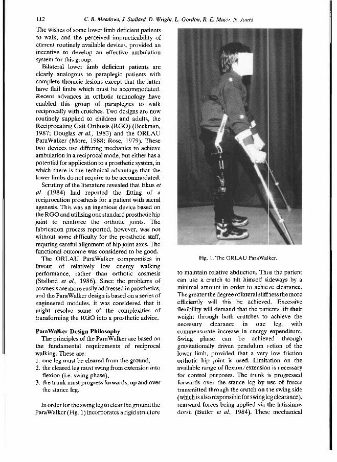
In order for the swing leg to clear the ground the Para Walker (Fig. 1) incorporates a rigid structure
to maintain relative abduction. Thus the patient can use a crutch to tilt himself sideways by a minimal amount in order to achieve clearance. The greater the degree of lateral stiffness the more efficiently will this be achieved. Excessive flexibility will demand that the patients lift their weight through both crutches to achieve the necessary clearance in one leg, with commensurate increase in energy expenditure. Swing phase can be achieved through gravitationally driven pendulum action of the lower limb, provided that a very low friction orthotic hip joint is used. Limitation on the available range of flexion/extension is necessary for control purposes. The trunk is progressed forwards over the stance leg by use of forces transmitted through the crutch on the swing side (which is also responsible for swing leg clearance), rearward forces being applied via the latissimus dorsii (Butler et al., 1984). These mechanical
Fig. 1. The ORLAU ParaWalker.
The Edinburgh-ORLA Uprosthetic system I 13
features demand a controlled input from a patient who has the necessary upper limb function. For this reason the ParaWalker forms part of a complete treatment system, the other essential elements being patient assessment and training. The orthosis is made up from a series of engineered components which are only supplied to clinical teams who have received the relevant training. This philosophy has permitted good clinical results to be achieved in both pacdiatric patients (ORLAU, 1983) and adults (Summers et al., 1988; Moore and Stallard, 1990).
Prosthetic design The essential similarity in biomechanical terms
between paraplegic and bilaterally lower limb deficient patients suggests that a prosthetic system with similar mechanical characteristics to the ParaWalker, incorporating modular lower limb components in place of orthotic stabilisation of the legs, should perform in an equivalent fashion. Such a system was produced for an eight year old girl with congenital bilateral absence of the lower limbs (she had a rudimentary left foot which was of no functional value for walking
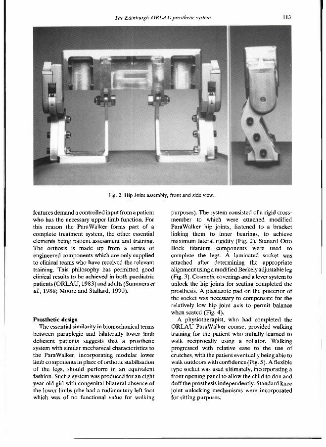
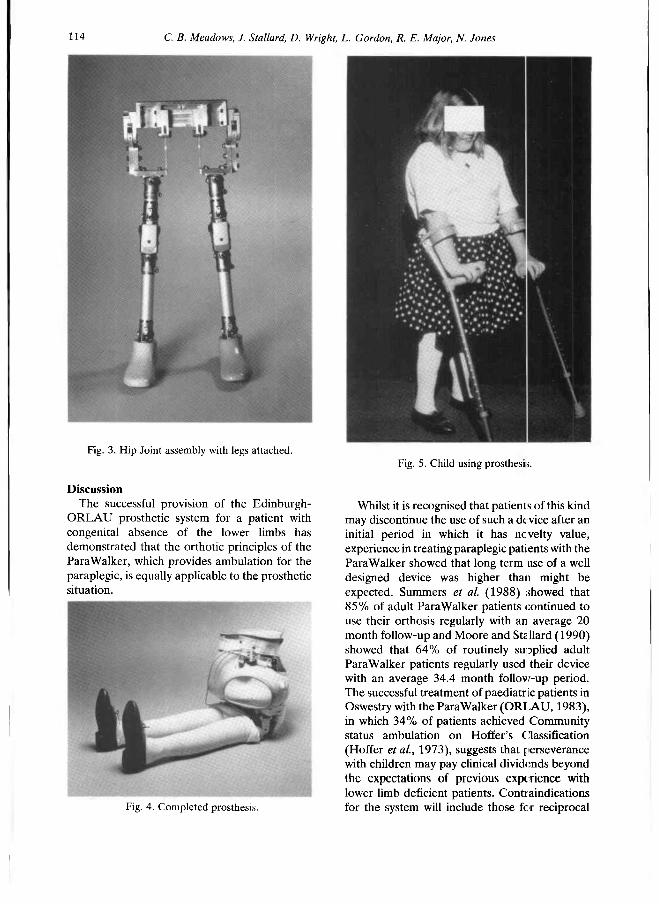
purposes). The system consisted of a rigid cross-member to which were attached modified ParaWalker hip joints, fastened to a bracket linking them to inner bearings, to achieve maximum lateral rigidity (Fig. 2). Stanard Otto Bock titanium components were used to complete the legs. A laminated socket was attached after determining the appropriate alignment using a modified Berkely adjustable leg (Fig. 3). Cosmetic coverings and a lever system to unlock the hip joints for seating completed the prosthesis. A plastazote pad on the posterior of the socket was necessary to compensate for the relatively low hip joint axis to permit balance when seated (Fig. 4).
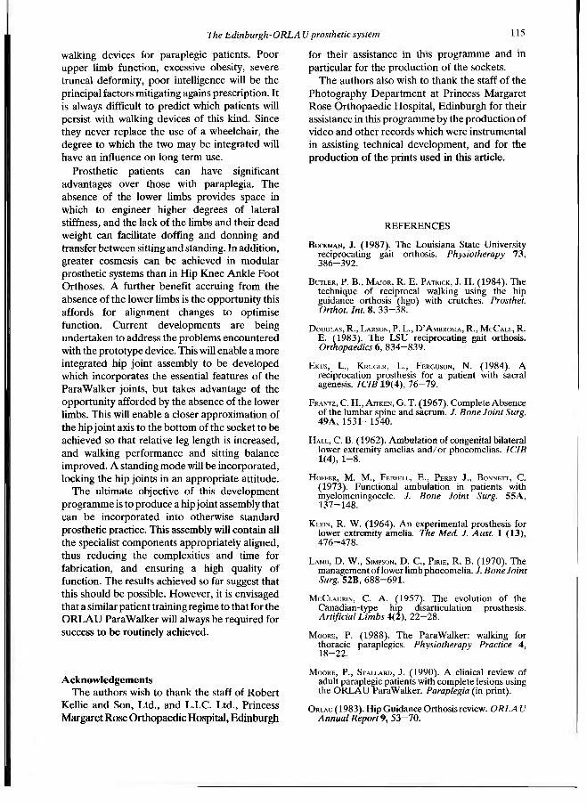
A physiotherapist, who had completed the O R L A U Para Walker course, provided walking training for the patient who initially learned to walk reciprocally using a rollator. Walking progressed with relative ease to the use of crutches, with the patient eventually being able to walk outdoors with confidence (Fig. 5). A flexible type socket was used ultimately, incorporating a front opening panel to allow the child to don and doff the prosthesis independently. Standard knee joint unlocking mechanisms were incorporated for sitting purposes.
Fig. 2. Hip Joint assembly, front and side view.
114 C. B. Meadows, J. Stallard, D. Wright, L. Gordon, R. E. Major, N. Jones
Discussion The successful provision of the Edinburgh-
ORLAU prosthetic system for a patient with congenital absence of the lower limbs has demonstrated that the orthotic principles of the Para Walker, which provides ambulation for the paraplegic, is equally applicable to the prosthetic situation.
Whilst it is recognised that patients of this kind may discontinue the use of such a device after an initial period in which it has novelty value, experience in treating paraplegic patients with the Para Walker showed that long term use of a well designed device was higher than might be expected. Summers et al. (1988) showed that 85% of adult Para Walker patients continued to use their orthosis regularly with an average 20 month follow-up and Moore and Stallard (1990) showed that 64% of routinely supplied adult Para Walker patients regularly used their device with an average 34.4 month follow-up period. The successful treatment of paediatric patients in Oswestry with the ParaWalker (ORLAU, 1983), in which 34% of patients achieved Community status ambulation on Hoffer's Classification (Hoffer et al., 1973), suggests that perseverance with children may pay clinical dividends beyond the expectations of previous experience with lower limb deficient patients. Contraindications for the system will include those for reciprocal
Fig. 3. Hip Joint assembly with legs attached.
Fig. 4. Completed prosthesis.
Fig. 5. Child using prosthesis.
The Edinburgh-ORLA Uprosthetic system 115
walking devices for paraplegic patients. Poor upper limb function, excessive obesity, severe truncal deformity, poor intelligence will be the principal factors mitigating again s prescription. It is always difficult to predict which patients will persist with walking devices of this kind. Since they never replace the use of a wheelchair, the degree to which the two may be integrated will have an influence on long term use.
Prosthetic patients can have significant advantages over those with paraplegia. The absence of the lower limbs provides space in which to engineer higher degrees of lateral stiffness, and the lack of the limbs and their dead weight can facilitate doffing and donning and transfer between sitting and standing. In addition, greater cosmesis can be achieved in modular prosthetic systems than in Hip Knee Ankle Foot Orthoses. A further benefit accruing from the absence of the lower limbs is the opportunity this affords for alignment changes to optimise function. Current developments are being undertaken to address the problems encountered with the prototype device. This will enable a more integrated hip joint assembly to be developed which incorporates the essential features of the Para Walker joints, but takes advantage of the opportunity afforded by the absence of the lower limbs. This will enable a closer approximation of the hip joint axis to the bottom of the socket to be achieved so that relative leg length is increased, and walking performance and sitting balance improved. A standing mode will be incorporated, locking the hip joints in an appropriate attitude.
The ultimate objective of this development programme is to produce a hip joint assembly that can be incorporated into otherwise standard prosthetic practice. This assembly will contain all the specialist components appropriately aligned, thus reducing the complexities and time for fabrication, and ensuring a high quality of function. The results achieved so far suggest that this should be possible. However, it is envisaged that a similar patient training regime to that for the O R L A U Para Walker will always be required for success to be routinely achieved.
Acknowledgements The authors wish to thank the staff of Robert
Kellie and Son, Ltd., and L.I.C. Ltd., Princess Margaret Rose Orthopaedic Hospital, Edinburgh
for their assistance in this programme and in particular for the production of the sockets.
The authors also wish to thank the staff of the Photography Department at Princess Margaret Rose Orthopaedic Hospital, Edinburgh for their assistance in this programme by the production of video and other records which were instrumental in assisting technical development, and for the production of the prints used in this article.
REFERENCES
BECKMAN, J . (1987). The Louisiana State University reciprocating gait orthosis. Physiotherapy 7 3 , 386-392.
BUTLER, P. B., MAJOR, R. E. PATRICK, J. H. (1984). The technique of reciprocal walking using the hip guidance orthosis (hgo) with crutches. Prosthet. Orthot. Int. 8 , 33-38.
DOUGLAS, R., LARSON, P. L., D'AMBROSIA, R., MCCALL, R. E. (1983). The LSU reciprocating gait orthosis. Orthopaedics 6 , 834-839.
EKUS, L., KRUGER, L., FERGUSON, N. (1984). A reciprocation prosthesis for a patient with sacral agenesis. ICIB 1 9 ( 4 ) , 76-79.
FRANTZ, C . H., AITKEN, G. T. (1967). Complete Absence of the lumbar spine and sacrum. /. Bone Joint Surg. 49A, 1531-1540.
HALL, C . B . (1962). Ambulation of congenital bilateral lower extremity amelias and/or phocomelias. ICIB 1 ( 4 ) , 1-8.
HOFFER, M . M . , FEIWELL, E., PERRY J., BONNETT, C . (1973). Functional ambulation in patients with myelomeningocele. J. Bone Joint Surg. 55A, 137-148.
KLEIN, R. W. (1964). An experimental prosthesis for lower extremity amelia. The Med. J. Aust. 1 ( 1 3 ) , 476-478.
LAMB, D . W., SIMPSON, D . C , PIRIE, R. B . (1970). The management of lower limb phocomelia. J. Bone Joint Surg. 5 2 B , 688-691.
MCCLAURIN, C . A. (1957). The evolution of the Canadian-type hip disarticulation prosthesis. Artificial Limbs 4 ( 2 ) , 22-28.
MOORE, P. (1988). The ParaWalker: walking for thoracic paraplegics. Physiotherapy Practice 4 , 18-22.
MOORE, P., STALLARD, J . (1990). A clinical review of adult paraplegic patients with complete lesions using the ORLAU ParaWalker. Paraplegia (in print).
ORLAU (1983). Hip Guidance Orthosis review. ORLAU Annual Report 9, 53-70.
116 C. B. Meadows, J. Stallard, D. Wright, L. Gordon, R. E. Major, N. Jones
ROSE, G. K. (1979). The principles and practice of hip guidance articulations. Prosthet. Orthot. Int. 3 , 37-43 .
SPEILREIN, R . E. (1963). An engineering approach to ambulation without the use of external power sources, of severely handicapped individuals. J. Inst. Eng., Aust. 3 5 , 321-326.
STALLARD, J . , MAJOR, R . E., POINTER, R. , FARMER, I. R. , JONES, N . ( 1 9 8 6 ) . Engineering design considerations of the O R L A U ParaWalker and FES hybrid system. Eng. Med. 1 5 , 1 2 3 - 1 2 9 .
SUMMERS, B. N . , MCCLELLAND, M . R . , EL MASRI, W. S. ( 1 9 8 8 ) . A clinical review of the adult hip guidance orthosis (ParaWalker) in traumatic paraplegics. Paraplegia 26, 19—26.
Prosthetics and Orthotics International, 1990, 14, 117—124
Stiffness and hysteresis properties of some prosthetic feet
H. W. L. VAN JAARSVELD*, H. J. GROOTENBOER*, J. DE VRIES†, and H. F. J. M. KOOPMAN*
*Department of Mechanical Engineering, University of Twente, Enschede, The Netherlands tRehabilitation Centre "Het Roessingh ", Enschede, The Netherlands
Abstract A prosthetic foot is an important element of a prosthesis, although it is not always fully recognized that the properties of the foot, along with the prosthetic knee joint and the socket, are in part responsible for the stability and metabolic energy cost during walking.
The stiffness and the hysteresis, which are the topics of this paper, are not properly prescribed, but could be adapted to improve the prosthetic walking performance. The shape is strongly related to the cosmetic appearance and so can not be altered to effect these improvements. Because detailed comparable data on foot stiffness and hysteresis, which are necessary to quantify the differences between different types of feet, are absent in literature, these properties were measured by the authors in a laboratory setup for nine different prosthetic feet, bare and with two different shoes. One test cycle consisted of measurements of load deformation curves in 66 positions, representing the range from heel strike to toe-off.
The hysteresis is defined by the energy loss as a part of the total deformation energy. Without shoes significant differences in hysteresis between the feet exist, while with sport shoes the differences in hysteresis between the feet vanish for the most part. Applying a leather shoe leads to an increase of hysteresis loss for all tested feet.
The stiffness turned out to be non-constant, so mean stiffness is used. Because very little is known about the optimal values of stiffness and hysteresis, and substantial differences in stiffness
between different feet and shoes exist, further investigation into the importance of stiffness and hysteresis to the walking quality of a foot is necessary. Footwear counts too for this quality because it modifies the variation in stiffness among the feet.
Introduction The influence of the mechanical properties of
the prosthetic foot on different aspects of gait is not yet fully understood. In conjunction with the prosthetic knee joint and socket, two important mechanical conditions are to be fulfilled: — the prosthesis has to support the body with
maximal stability during the stance phase, which means for example that the resultant ground reaction force has to pass in front of the instantaneous centre of rotation of the knee joint.
— walking with a prosthesis has to demand as little energy as possible. Four mechanical properties of the foot
influence the stability and energy consumption and affect of the roll-over behaviour of the foot: — the shape and the alignment of the foot, along
with the pylon angle, determine the point of application of the ground reaction force on the foot. The shape also influences the vertical and horizontal movement of prosthesis and body during gait, as is shown by Koopman (1989). Foot shape is not considered in this paper,
— the mass and mass-distribution of the foot affect the swing behaviour of the leg (Van de Veen, 1989). Donn et al. (1989) showed in an experimental study that an optimal choice of the mass can significantly improve some symmetry coefficients of walking. The mass-
All coπespondece to be sent to Prof. dr. ir. H. J. Grootenboer, Lab. for Biomechanics, Faculty of Mechanical Engineering, University of Twente, P.O. Box 217, 7500 A E Enschede, The Netherlands.
117
118 H. W. L. van Jaarsveld, H. J. Grootenboer, J. de Vries, H. F. J. M. Koopman
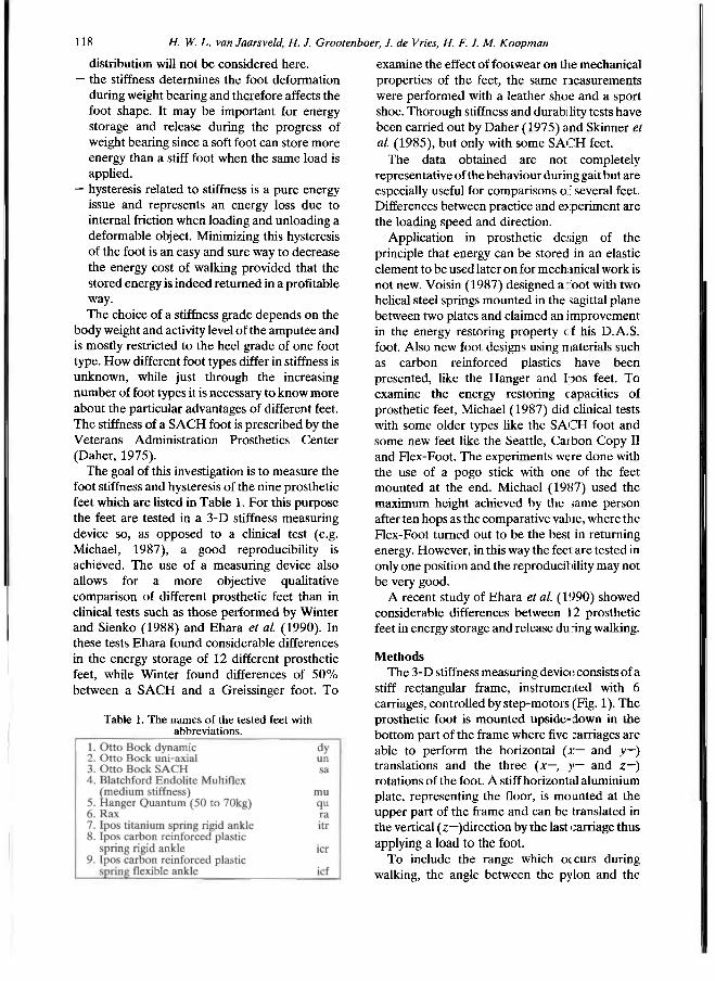
distribution will not be considered here. — the stiffness determines the foot deformation
during weight bearing and therefore affects the foot shape. It may be important for energy storage and release during the progress of weight bearing since a soft foot can store more energy than a stiff foot when the same load is applied.
— hysteresis related to stiffness is a pure energy issue and represents an energy loss due to internal friction when loading and unloading a deformable object. Minimizing this hysteresis of the foot is an easy and sure way to decrease the energy cost of walking provided that the stored energy is indeed returned in a profitable way. The choice of a stiffness grade depends on the
body weight and activity level of the amputee and is mostly restricted to the heel grade of one foot type. How different foot types differ in stiffness is unknown, while just through the increasing number of foot types it is necessary to know more about the particular advantages of different feet. The stiffness of a SACH foot is prescribed by the Veterans Administration Prosthetics Center (Daher, 1975).
The goal of this investigation is to measure the foot stiffness and hysteresis of the nine prosthetic feet which are listed in Table 1. For this purpose the feet are tested in a 3-D stiffness measuring device so, as opposed to a clinical test (e.g. Michael, 1987), a good reproducibility is achieved. The use of a measuring device also allows for a more objective qualitative comparison of different prosthetic feet than in clinical tests such as those performed by Winter and Sienko (1988) and Ehara et al. (1990). In these tests Ehara found considerable differences in the energy storage of 12 different prosthetic feet, while Winter found differences of 50% between a SACH and a Greissinger foot. To
examine the effect of footwear on the mechanical properties of the feet, the same measurements were performed with a leather shoe and a sport shoe. Thorough stiffness and durability tests have been carried out by Daher (1975) and Skinner et al. (1985), but only with some SACH feet.
The data obtained are not completely representative of the behaviour during gait but are especially useful for comparisons of several feet. Differences between practice and experiment are the loading speed and direction.
Application in prosthetic design of the principle that energy can be stored in an elastic element to be used later on for mechanical work is not new. Voisin ( 1987) designed a bot with two helical steel springs mounted in the sagittal plane between two plates and claimed an improvement in the energy restoring property cf his D.A.S. foot. Also new foot designs using materials such as carbon reinforced plastics have been presented, like the Hanger and IpOS feet. To examine the energy restoring capacities of prosthetic feet, Michael (1987) did clinical tests with some older types like the SACH foot and some new feet like the Seattle, Carbon Copy I I and Flex-Foot. The experiments were done with the use of a pogo stick with one of the feet mounted at the end. Michael (1987) used the maximum height achieved by the same person after ten hops as the comparative value, where the Flex-Foot turned out to be the best in returning energy. However, in this way the feel are tested in only one position and the reproducibility may not be very good.
A recent study of Ehara et al. (1990) showed considerable differences between 12 prosthetic feet in energy storage and release during walking.
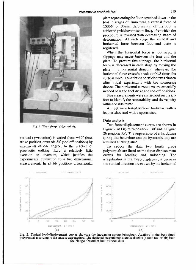
Methods The 3-D stiffness measuring device consists of a
stiff rectangular frame, instrumented with 6 carriages, controlled by step-motors (Fig. 1). The prosthetic foot is mounted upside-down in the bottom part of the frame where five carriages are able to perform the horizontal (x— and y—) translations and the three (x—, y— and z—) rotations of the foot. A stiff horizontal aluminium plate, representing the floor, is mounted at the upper part of the frame and can be translated in the vertical (z—)direction by the last carriage thus applying a load to the foot.
To include the range which occurs during walking, the angle between the pylon and the
Table 1. The names of the tested feet with abbreviations.
Properties of prosthetic feet 119
vertical (y—rotation) is varied from —30° (heel strike position) towards 35° (toe-off position) by increments of one degree. In the practice of prosthetic walking there is relatively little eversion or inversion, which justifies the experimental restriction to a two dimensional measurement. In all 66 positions a horizontal
plate representing the floor is pushed down on the foot in stages of 1mm until a vertical force of 1000N or 35mm deformation of the foot is achieved (whichever occurs first), after which the procedure is reversed with decreasing stages of deformation. At each stage the vertical and horizontal force between foot and plate is registered.
When the horizontal force is too large, a slippage may occur between the foot and the plate. To prevent this slippage, the horizontal force is decreased in each stage by moving the plate in a horizontal direction whenever the horizontal force exceeds a value of 0.3 times the vertical force. This friction coefficient was chosen after initial experiments with the measuring device. The horizontal corrections are especially needed near the heel strike and toe-off positions.
Five measurements were carried out on the icf-foot to identify the repeatability, and the velocity influence was tested.
All feet were tested without footwear, with a leather shoe and with a sports shoe.
Data analysis Two force-displacement curves are shown in
Figure 2: in Figure 2a position —30° and in Figure 2b position 35°. The appearance of a hardening spring-like behaviour and the hysteresis loop are revealed at first glance.
To reduce the data two fourth grade polynomials are fitted on the force-displacement curves for loading and unloading. The irregularities in the force-displacement curve in the vertical direction are caused by the horizontal
Fig. 1. The set-up of the test rig.
Fig. 2. Typical load-displacement curves showing the hardening spring behaviour. Auxilary is the best fitted polynomial according to the least square method. The depicted measurements are heel strike (a) and toe-off (b) from
the Hanger Quantum foot without shoe.
120 H. IV- L. van Jaarsvetd, H. J. Grooleπboer, J. de Vries, H. F. J. M. Koopman
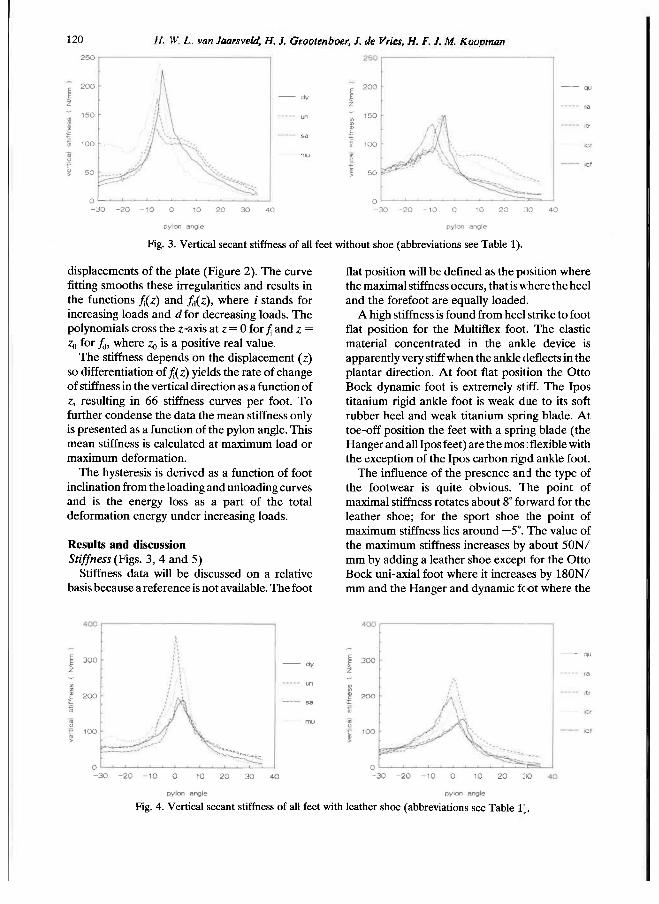
displacements of the plate (Figure 2). The curve fitting smooths these irregularities and results in the functions fi(z) and f d(z), where i stands for increasing loads and d for decreasing loads. The polynomials cross the z-axis at z = 0 for fi and z = z0, for fd, where z0 is a positive real value.
The stiffness depends on the displacement (z) so differentiation of fi(z) yields the rate of change of stiffness in the vertical direction as a function of z, resulting in 66 stiffness curves per foot. To further condense the data the mean stiffness only is presented as a function of the pylon angle. This mean stiffness is calculated at maximum load or maximum deformation.
The hysteresis is derived as a function of foot inclination from the loading and unloading curves and is the energy loss as a part of the total deformation energy under increasing loads.
Results and discussion Stiffness (Figs. 3, 4 and 5)
Stiffness data will be discussed on a relative basis because a reference is not available. The foot
flat position will be defined as the position where the maximal stiffness occurs, that is where the heel and the forefoot are equally loaded.
A high stiffness is found from heel strike to foot flat position for the Multiflex foot. The elastic material concentrated in the ankle device is apparently very stiff when the ankle deflects in the plantar direction. At foot flat position the Otto Bock dynamic foot is extremely stiff. The Ipos titanium rigid ankle foot is weak due to its soft rubber heel and weak titanium spring blade. At toe-off position the feet with a spring blade (the Hanger and all Ipos feet) are the mos : flexible with the exception of the Ipos carbon rigid ankle foot.
The influence of the presence and the type of the footwear is quite obvious. The point of maximal stiffness rotates about 8° forward for the leather shoe; for the sport shoe the point of maximum stiffness lies around —5°. The value of the maximum stiffness increases by about 50N/ mm by adding a leather shoe except for the Otto Bock uni-axial foot where it increases by 180N/ mm and the Hanger and dynamic foot where the
Fig. 3. Vertical secant stiffness of all feet without shoe (abbreviations see Table 1).
Fig. 4. Vertical secant stiffness of all feet with leather shoe (abbreviations see Table V.
Properties of prosthetic feel 121
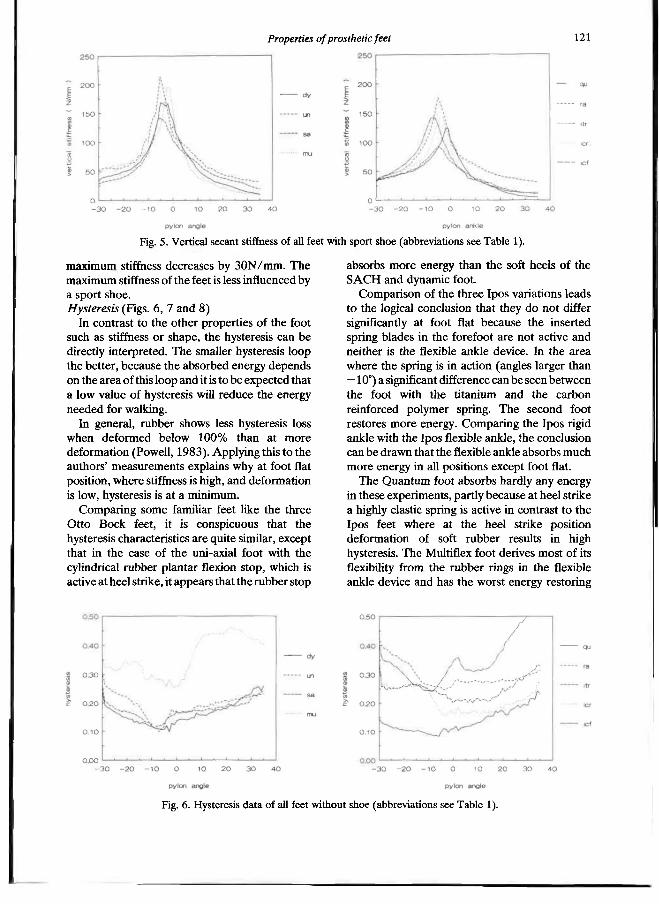
maximum stiffness decreases by 30N/mm. The maximum stiffness of the feet is less influenced by a sport shoe. Hysteresis (Figs. 6, 7 and 8)
In contrast to the other properties of the foot such as stiffness or shape, the hysteresis can be directly interpreted. The smaller hysteresis loop the better, because the absorbed energy depends on the area of this loop and it is to be expected that a low value of hysteresis will reduce the energy needed for walking.
In general, rubber shows less hysteresis loss when deformed below 100% than at more deformation (Powell, 1983). Applying this to the authors' measurements explains why at foot flat position, where stiffness is high, and deformation is low, hysteresis is at a minimum.
Comparing some familiar feet like the three Otto Bock feet, it is conspicuous that the hysteresis characteristics are quite similar, except that in the case of the uni-axial foot with the cylindrical rubber plantar flexion stop, which is active at heel strike, it appears that the rubber stop
absorbs more energy than the soft heels of the SACH and dynamic foot.
Comparison of the three Ipos variations leads to the logical conclusion that they do not differ significantly at foot flat because the inserted spring blades in the forefoot are not active and neither is the flexible ankle device. In the area where the spring is in action (angles larger than —10°) a significant difference can be seen between the foot with the titanium and the carbon reinforced polymer spring. The second foot restores more energy. Comparing the Ipos rigid ankle with the Ipos flexible ankle, the conclusion can be drawn that the flexible ankle absorbs much more energy in all positions except foot flat.
The Quantum foot absorbs hardly any energy in these experiments, partly because at heel strike a highly elastic spring is active in contrast to the Ipos feet where at the heel strike position deformation of soft rubber results in high hysteresis. The Multiflex foot derives most of its flexibility from the rubber rings in the flexible ankle device and has the worst energy restoring
Fig. 5. Vertical secant stiffness of all feet with sport shoe (abbreviations see Table 1).
Fig. 6. Hysteresis data of all feet without shoe (abbreviations see Table 1).
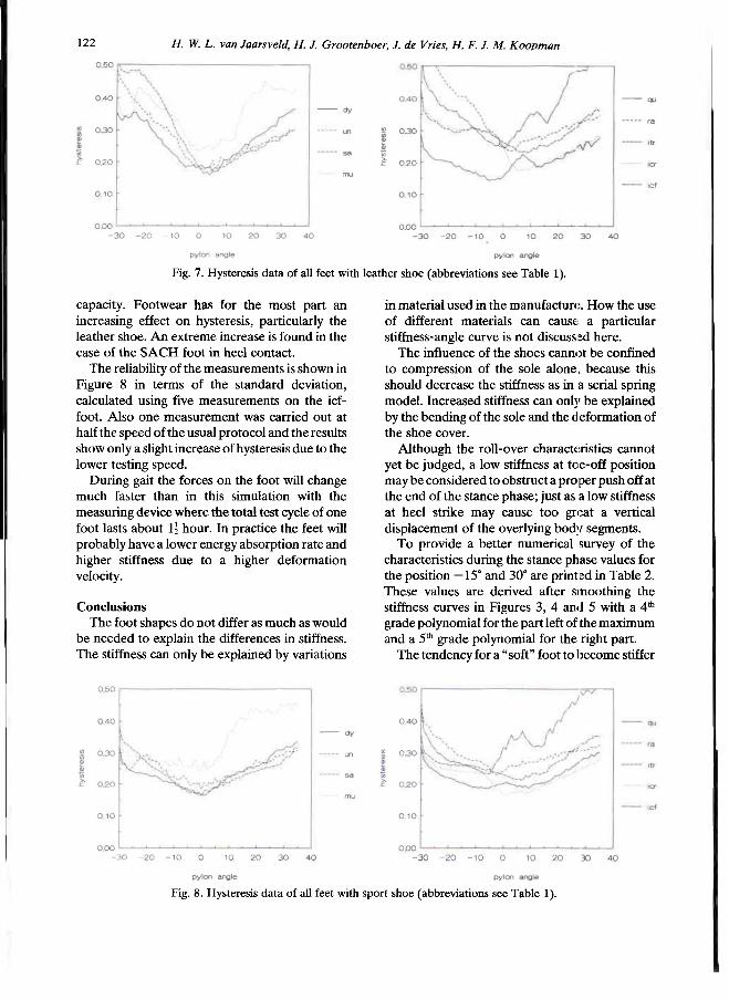
122 H. W. L. van Jaarsveld. H. J. Grootenboer, J. de Vries, H. F. J. M. Koopman
capacity. Footwear has for the most part an increasing effect on hysteresis, particularly the leather shoe. An extreme increase is found in the case of the SACH foot in heel contact.
The reliability of the measurements is shown in Figure 8 in terms of the standard deviation, calculated using five measurements on the icf-foot. Also one measurement was carried out at half the speed of the usual protocol and the results show only a slight increase of hysteresis due to the lower testing speed.
During gait the forces on the foot will change much faster than in this simulation with the measuring device where the total test cycle of one foot lasts about 1 1/2 hours. In practice the feet will probably have a lower energy absorption rate and higher stiffness due to a higher deformation velocity.
Conclusions The foot shapes do not differ as much as would
be needed to explain the differences in stiffness. The stiffness can only be explained by variations
in material used in the manufacture. How the use of different materials can cause a particular stiffness-angle curve is not discussed here.
The influence of the shoes cannot be confined to compression of the sole alone, because this should decrease the stiffness as in a serial spring model. Increased stiffness can only be explained by the bending of the sole and the deformation of the shoe cover.
Although the roll-over characteristics cannot yet be judged, a low stiffness at toe-off position may be considered to obstruct a proper push off at the end of the stance phase; just as a low stiffness at heel strike may cause too great a vertical displacement of the overlying body segments.
To provide a better numerical survey of the characteristics during the stance phase values for the position —15° and 30° are printed in Table 2. These values are derived after smoothing the stiffness curves in Figures 3, 4 and 5 with a 4th
grade polynomial for the part left of the maximum and a 5 t h grade polynomial for the right part.
The tendency for a "soft" foot to become stiffer
Fig. 7. Hysteresis data of all feet with leather shoe (abbreviations see Table 1).
Fig. 8. Hysteresis data of all feet with sport shoe (abbreviations see Table 1).

Properties of prosthetic feet 123
and a "stiff' foot softer by using a shoe in both positions is remarkable. This tendency can be explained by the deformation of the shoe cover and the bending of the shoe sole, the effects of which are large in comparison to a flabby foot and small in comparison to a stiff foot. Trying to represent this in a spring model would give the foot in parallel with the shoe-cover and both in series with the shoe-sole. In Table 2 the distinction between the "soft" and "stiff" feet is shown by the dotted line and the exceptions to the rule are printed in a bold type face. At 30° this change over for a sport shoe is much smaller than
for a leather shoe, caused by the large difference in stiffness of the cover at the forefoot of both shoes.
An indication is given to explain the modifying influences of the footwear on several feet. To actually prove the spring model thesis, measurements with shoe parts would be required.
As far as the hysteresis is concerened, if as low a value as possible is to be recommended, the Hanger Quantum foot proves to be the best of all feet examined using this experimental setup.
In general we may conclude that uni- and multi-axial feet absorb more energy than feet with a rigid ankle device due to the hysteresis in the deformation of the rubber parts and friction in the axis. When adding a leather shoe the hysteresis increases for all feet except for the Multiflex foot, and for the Ipos foot with the flexible ankle which shows only a little increase.
To investigate the behaviour of the footwear at —15° and 30°, an 8th grade polynomial is used to smooth the data before presentation in Table 3. At 30° almost all feet show an increase in hysteresis on adding a shoe and it appears that the smaller the hysteresis without a shoe, the larger the increase with one. At —15° where there is a high hysteresis without shoe a decrease occurs for the sport shoe which is accented by the dotted line in Table 3 but on the other hand an increase is
Table 2. Stiffness values at two positions after smoothing with polynomials. (wi = without shoe, le = with leather shoe, sp = with sport shoe.)
Fig. 9. Reliability indication of the hysteresis after five tests and one test at half the speed.
Table 3. Hysteresis values at two positions after smoothing with polynomials, (wi = without shoe, le = with leather shoe, sp = with sport shoe.)
124 H. W. L. van Jaarsveld, H. J. Grootenboer, J. de Vries, H. F. J. M. Koopman
observed for the leather shoe. Because the reducing effect is most active at —15° for the sport shoe it may be concluded that the heel deformation of the sport shoe causes less auxiliary hysteresis in comparison to the leather shoe.
The smaller hysteresis for the sport shoe when compared with the leather shoe is a striking result. Taking into consideration the increased shock absorption of prosthetic feet when combined with sport shoes, compared to leather shoes, amputees can for the improvement of this particular characteristic, be recommended to walk on sport shoes instead of stiff leather shoes.
The Ipos and Hanger feet are designed on the principle which separates two functions of the foot: the mechanical properties and the cosmetic appearance. A soft rubber coating is necessary for cosmetic reasons and scarcely contributes to the mechanical properties. Hanger manufacturers succeeded in avoiding dissipative rubber elements in their design, resulting in a low energy absorbing foot.
REFERENCES
DAHER, R. L. (1975) . Physical response of SACH feet under laboratory testing. Bult. Prosthet. Res. 1 0 ( 2 3 ) , 4 - 5 0 .
DONN, J. M., PORTER, D,, ROBERTS, V . C. (1989) . The effect of footwear mass on the gait patterns of unilateral below-knee amputees. Prosthet. Orthot. Int. 1 3 , 1 4 0 - 1 4 4 .
EHARA, Y . , BEPPPU, M., NOMURA, S., KUNIMI, Y . , TAKAKASHI, S. (1990) . Energy analysis of energy-storing prosthetic feet. In: Proceedings International Symposium Gait Analysis, 2—3 February 1990, Berlin.
KOOPMAN, H. F. J. M . (1989) . The three-dimensional analysis and prediction of human walking. Ph.D. thesis. Enschede, The Netherlands: University of Twente.
MICHAEL, J. W . (1987) . Energy storinf; feet: a clinical comparison. Clin. Prosthet. Orthot. 1 1 , 1 5 4 - 1 6 8 .
POWELL, P. C. (1933) . Engineering with polymers. London: Chapman and Hall.
SKINNER, H. B., ABRAHAMSON, M . A., HUNG, R . K . , WILSON, L. A. , EFFENEY, D. J. (1985) . Static load response of the heels of SACH feet. Orthopedics 8 , 2 2 5 - 2 2 8 .
VEEN, P. G. VAN DE (1989) . An investigation of design criteria of modular endoskeletal lower limb prosthesis. Ph.D. thesis, Enshede, The Netherlands: University of Twente.
VOISIN, J. P. (1987) . Dual-ankle springs (D.A.S. ) foot-ankle system. Orthot. Prosthet. 4 0 , 27—36.
WINTER, D. A. , SIENKO, S. E . (1988) . Biomechanics of below-knee amputee gait. J. Biomech. 2 1 , 361—367.
Prosthetics and Orthotics International, 1990, 14, 125—135
Analysis of the swing phase dynamics and muscular effort of the above-knee amputee for varying prosthetic shank loads
S. A. HALE
Kawartha Orthopaedics Ltd, Peterborough, Ontario, Canada
Abstract The purpose of this study was to determine the effect of varying prosthetic shank mass, while maintaining the mass centre location and moment of inertia, on the swing phase kinematics, kinetics and hip muscular effort of free speed above-knee (AK) amputee gait. Six AK amputees, wearing similar prosthetic designs, had three load conditions applied to their prosthetic shank: 1) Load 0-unloaded (X = 39.1% sound shank mass), 2) Load 1- 75%, and 3) Load 2 -100% sound leg mass. Despite increases in shank mass from 1.33 to 3.37 kg the AK amputee was able to maintain a consistent swing time and walking speed. As load increased, there were significant changes in the maximum knee and hip displacements, as well as phasic shifting. The prosthetic knee Resultant Joint Moment (RJM) was negligible while the shank was accelerating (periods 1 and 2), but was a major contributor during shank deceleration (periods 3 and 4). During periods 1 and 2 the principle contributors to the shank acceleration (forces resisting excessive knee flexion) were the gravitational moment (S-G) and the moment due to thigh angular acceleration (S-AT). During the periods of shank acceleration (sections 1 and 2), there was not a significant increase in the hip muscular effort. However, during sections 3 and 4, the periods associated with shank deceleration, there were siginficant increases in the hip muscular effort. The hip muscular effort for the complete swing phase increased as load increased by 36.7% and 71.3% for loads 1 and 2. Despite the significant increases in hip muscular effort, four of the six subjects preferred load 1 condition,
Introduction Due to the loss of normal knee and ankle
function in the AK amputee, changes in the joint angular patterns and compensations at the muscular level would be expected. The knee angular displacement pattern for AK amputees (Hicks et al., 1985; Murray et al., 1980 and 1983) is similar to that of the normal subject (Murray, 1967; Winter, 1984). However, the AK amputee hip angular displacement pattern differs by exhibiting a final phase of hip flexion after the normal flexion and extension periods (Murray et al., 1980 and 1983) or an extra flexion and extension period (Frigo and Tesio, 1986; Hale and Putnam, 1987). The typical AK amputee knee moment (torque) pattern is similar to the normal subject pattern of extension followed by flexion, except the AK amputee exhibits lower peak magnitudes (Hale and Putnam, 1987; Hoy et al., 1983; Judge, 1978). On the other hand, the AK hip muscular moment pattern exhibits intermediary extensor and flexor moments during the midswing stage (Hale and Putnam, 1987), between the normal pattern (Winter, 1984) of an initial flexor and final extensor moment.
Several investigators have suggested that changes in the segment inertial parameters — mass, mass centre location and moment of inertia of the prosthesis also influence the swing pattern of the AK amputee (Menkveld et al., 1981; Tashman et al., 1985). No significant changes were recorded in the stride length, stance time, knee angle or the rate of heel rise for six subjects when two loads were applied to the prosthetic foot (Godfrey et al., 1977). Tashman et al.
Work was carried out at the School of Physical Education, Dalhousie University, Halifax, Nova Scotia, and the Department of Kinanthropology at the University of Ottawa, Ottawa, Ontario, Canada.
All correspondence to be addressed to S. Hale, Kawartha Orthopaedics Ltd, St. Joseph's Hospital, 384 Rogers Road, Peterborough, Ontario, Canada K9H 7B6.
125

126 S. A. Hale
(1985) reduced the moment of inertia of a single AK prosthesis which resulted in lowering the natural swing period of the prosthesis. This, in turn, reduced the swing time and maximum knee flexion, and improved gait symmetry. Increasing the prosthetic shank mass and changing the mass centre location and moment of inertia, to near normal values, of a single AK subject resulted in increases in the stride length and walking speed, and was accompanied by a decreased hip muscular moment (Menkveld et al., 1981).
The current trend in prosthetic designs is toward lightweight prostheses, as seen by the use of lightweight materials such as titanium and carbon fibre. It was expected that with the lighter prosthesis, less muscular effort would be required to advance the swing limb forward (Murphy, 1964). It was speculated that if the prosthetic limb had a similar mass and moment of inertia to that of the anatomical limb, the amputee would require three times the normal hip muscle exertion (Eberhart et al., 1968). The problems encountered in the AK amputee swing phase in limiting their walking speed may be solved with proper prosthetic design, but the solution to these problems and the implication on muscular effort are not well understood.
The purpose of this study was to determine the effect of loading the prosthetic shank, (while maintaining the mass centre location and moment of inertia), on the joint and segment angular kinematics, the forces acting on the prosthetic shank, and the hip muscular effort during the swing phase of free speed AK amputee gait.
Methodology The following criteria were used for subject
selection: 1) male, 2) between the ages of 18 and 65 years, 3) unilateral above-knee (trans-femoral) amputation, 4) prosthesis user for a minimum of one year, 5) body weight (without prosthesis) between 50 and 70 kg, 6) previously used the experimental prosthesis, and 7) clinically classified as a "good to excellent" walker. Six subjects were asked to participate, informed of the experimental procedure and written consents obtained. Subject descriptive information is provided in Table 1.
All subjects wore the following AK prosthetic design: 1) Otto Block (OB) endoskeletal system, 2) either a rigid quadrilateral ischial weight-bearing, total contact socket (New York University, 1982) or an Icelandic, Swedish, New
York (ISNY) flexible socket (Kristinsson, 1983), 3) suspension by either suction, or silesian belt or a hip joint and pelvic band, 4) an OB 3R15 knee unit with swing and stance controls, 5) an extension assist unit (OB 21B30), 6) an OB 4R2 pylon, and 7) a single axis OB 1H32 ankle/foot unit.
Three experimental load conditions were selected: 1) load 0, the unweighted prosthetic shank plus unshod foot (X = 39.1% the anatomic leg mass); 2) load 1, the prosthetic shank mass was increased to 75% subject's sound shank mass; 3) load 2, the prosthetic shank and foot was increased to 100%. The sound shank plus foot mass was estimated using data presented by Dempster (1959) and corrected for the subject's height and weight. The load was applied about the mass centre location (CM) to mnimize the changes in the CM and moment of inertia. The mass and moment of inertia for each load condition are presented in Table 2.
The lower limb was modelled as a rigid two link system (Fig. 1). The segment inertial parameters of the prosthetic thigh and shank were determined using a weigh scale (mass), knife-edge balance beam (mass centre location) and a specially designed pendulum (moment of inertia). The mass of the residual thigh was estimated using Dempster's cadaver data, corrected for the subject's height and weight, and taken as a percentage of the remaining thigh length. The residual thigh mass centre location and moment of inertia were mathematically determined using known equations for a right frustrum of a cone with a uniform density (Beer and Johnston, 1976). The inertial characteristics of the residual thigh and prosthetic thigh section were combined to give the total thigh characteristics.
The subjects were asked to walk at a self
Table 1
Subject descriptive data
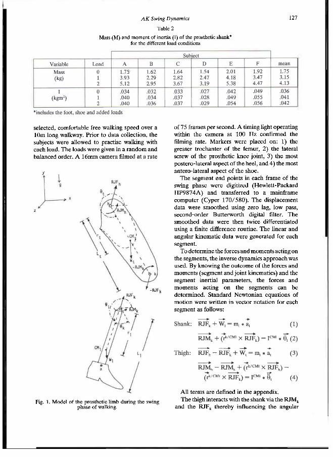
AK Swing Dynamics 127
selected, comfortable free walking speed over a 10m long walkway. Prior to data collection, the subjects were allowed to practise walking with each load. The loads were given in a random and balanced order. A 16mm camera filmed at a rate
of 75 frames per second. A timing light operating within the camera at 100 Hz confirmed the filming rate. Markers were placed on: 1) the greater trochanter of the femur, 2) the lateral screw of the prosthetic knee joint, 3) the most postero-lateral aspect of the heel, and 4) the most antero-lateral aspect of the shoe.
The segment end points in each frame of the swing phase were digitized (Hewlett-Packard HP9874A) and transferred to a mainframe computer (Cyper 170/580). The displacement data were smoothed using zero lag, low pass, second-order Butterworth digital filter. The smoothed data were then twice differentiated using a finite difference routine. The linear and angular kinematic data were generated for each segment.
To determine the forces and moments acting on the segments, the inverse dynamics approach was used. By knowing the outcome of the forces and moments (segment and joint kinematics) and the segment inertial parameters, the forces and moments acting on the segments can be determined. Standard Newtonian equations of motion were written in vector notation for each segment as follows:
All terms are defined in the appendix. The thigh interacts with the shank via the RJM k
and the RJF k thereby influencing the angular
Table 2
Mass (M) and moment of inertia (I) of the prosthetic shank* for the different load conditions
Fig. 1. Model of the prosthetic limb during the swing phase of walking.
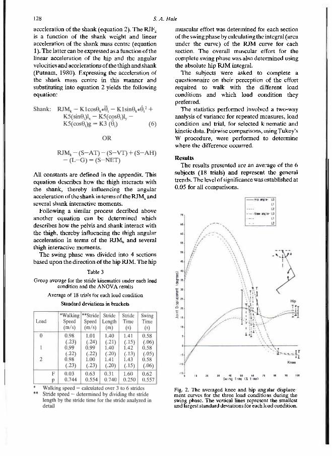
128 S. A. Hale
acceleration of the shank (equation 2). The RJF k
is a function of the shank weight and linear acceleration of the shank mass centre (equation 1). The latter can be expressed as a function of the linear acceleration of the hip and the angular velocities and accelerations of the thigh and shank (Putnam, 1980). Expressing the acceleration of the shank mass centre in this manner and substituting into equation 2 yields the following equation:
All constants are defined in the appendix. This equation describes how the thigh interacts with the shank, thereby influencing the angular acceleration of the shank in terms of the RJM k and several shank interactive moments.
Following a similar process decribed above another equation can be determined which describes how the pelvis and shank interact with the thigh, thereby influencing the thigh angular acceleration in terms of the RJM h and several thigh interactive moments.
The swing phase was divided into 4 sections based upon the direction of the hip RJM. The hip
muscular effort was determined for each section of the swing phase by calculating the integral (area under the curve) of the RJM curve for each section. The overall muscular effort for the complete swing phase was also determined using the absolute hip RJM integral.
The subjects were asked to complete a questionnaire on their perception of the effort required to walk with the different load conditions and which load condition they preferred.
The statistics performed involved a two-way analysis of variance for repeated measures, load condition and trial, for selected kinematic and kinetic data. Pairwise comparisons, using Tukey's W procedure, were performed to determine where the difference occurred.
Results The results presented are an average of the 6
subjects (18 trials) and represent the general trends. The level of significance was established at 0.05 for all comparisons.
Table 3
Group average for the stride kinematics under each load condition and the A N O V A results
Average of 18 trials for each load condition
Standard deviations in brackets
Fig. 2. The averaged knee and hip angjlar displacement curves for the three load conditions during the swing phase. The vertical lines represent the smallest and largest standard deviations for each load condition.

AK Swing Dynamics 129
Stride Kinematics Table 3 summarized the stride kinematics
across each load condition. Increasing the prosthetic shank mass up to 100% sound shank mass had no significant effect on the stride kinematic variables.
Angular Kinematics The knee angle was defined as the included
knee angle as indicated in Figure 2. The knee angle used in equation 6 was equal to:
180° — included knee angle. The thigh angle (Fig. 2), which approximately
equates to the hip angle, was expressed as: thigh angle — 270°. The shank and thigh acceleration curves for the
three load conditions during the swing phase are illustrated in Figure 3.
Angular Kinetics Moment contributions to shank acceleration The mean impulses of the moments acting on
the shank were compared across loads and the four sections in Figure 4.
Knee and hip RJM patterns The knee RJM pattern (Fig. 5) exhibited initial
low extensor (load condition 0) or flexor moment (loads 1 and 2) followed by an increasing flexor moment. The averaged hip RJM pattern (Fig. 5) for the 3 loads, exhibited 4 sections: 1) an initial flexor, followed by 2) an extensor, then 3) a flexor and ending with 4) a final extensor moment.
Muscular Effort The group mean hip muscular effort for each
section and the complete swing phase are shown in Figure 6. In sections 1 and 2 there were no significant increases in the hip muscular effort. In sections 3 and 4 as load increased there were significant increases in the hip RJM impulse. The absolute hip RJM impulse for the complete swing phase significantly increased from 3.24 ± 1.47 Nms to 4.43 ± 1.81 and 5.55 ± 1.82 Nms for loads 1 and 2, respectively.
Fig. 3. The averaged shank and thigh angular acceleration curves for the three load conditions during the swing phase. The vertical lines represent the smallest and largest standard deviations for each load condition.
Fig. 4. The averaged impulses of the moments acting on the prosthetic shank during the four sections of the swing phase. The vertical lines represent the standard
deviation for each variable.

13ü 5. A. Hale
Subjective Evaluation Table 4 presents the subjects' preference of the
load condition, taken from the questionnaire. Four of the six subjects preferred load condition 1 (75% anatomic shank mass). The remaining two subjects preferred load 0 condition (unweighted prosthetic shank).
The primary reasons given for choosing load 1 were: 1) more control, 2) less strenuous, 3) easier to swing the prosthesis, 4) smoother swing, and 5) improved consistency in walking. The reasons given for selecting load 0 by the two subjects were: 1 ) less weight to lift, 2) less effort required to walk, and 3) improved socket comfort.
Discussion Despite the attempt to maintain the moment of
inertia, it increased up to 28.5% (subject F), with a mean increase of 16.7%. The mass centre was
assumed to be unchanged since the load was applied about it. Changes in the moment of inertia could be attributed to the size of the: load applied about the mass centre, the irregularity of its shape and positioning of the load.
Fig. 5. The averaged knee and hip resultant joint moments (RJM) for the three load conditions during the swing phase. The vertical lines represent the smallest and largest standard deviations for each load condition.
Table 4
Subject preference of the different prosthetic shank masses
(The order of perference is from the most desirable (i) to the least desirable (iii).)
Fig. 6. The averaged hip muscular impulse (effort) for the four sections of the swing phase and for the complete swing phase for the three load conditions. The vertical lines represent the standard deviation for each load condition in each section, a) Significant difference between loads 0 and 1. b) Significant difference between loads 1 and 2. c) Significant difference between loads 0 and 2. d) Significant difference
between all loads.
AK Swing Dynamics 131
The consistent walking and stride speeds across loads were similar to previous studies on the effect of altered segment inertial parameters on AK gait (Godfrey et al., 1977; Tashman et al., 1985). The findings suggest that AK amputees can attain a free and comfortable walking speed when the prosthetic shank mass is increased to 100% of the remaining shank. However, the gait may change if the patient would be required to walk for a longer period with the heavier loads.
As load increased the maximum knee flexion attained significantly decreased (p < .0334). The time at which this angle was reached occurred significantly earlier (p < .0460). The time when full extension was attained occurred significantly earlier as load increased (p < .0006). The knee angle patterns were similar to previous AK studies where the amputees used constant friction knee units (Frigo and Tesio, 1986; Murray et al., 1980 and 1983).
The thigh (hip) displacement pattern differed from the normal pattern of flexion followed by extension (Murray, 1967; Winter, 1984), but was similar to previous AK studies (Frigo and Tesio, 1986; Hale and Putnam, 1987; Murray et al., 1980 and 1983). The thigh curves exhibited a double flexion peak separated by a valley. The initial peak flexion angle significantly decreased (p < .0215) and occurred earlier (p < .0007) as prosthetic shank mass increased. The thigh then began to extend reaching a local minimum flexion angle which significantly decreased (p < .0116) and occurred earlier (p < .0003). The thigh reversed direction reaching a final peak flexion, which in turn significantly increased (p < .0175) as load increased. Finally, the thigh briefly extended to end the swing phase. It has been previously suggested that the nature of the knee and hip (thigh) patterns were probably related to the characteristics and function of the AK prosthesis (Frigo and Tesio, 1986) and that the prosthetic knee could be controlled by newly learned hip motion and residual thigh patterns (Murphy, 1964). The changes in magnitude and the phasic shifts in the peaks and valleys of the thigh displacement curves suggest that the AK amputee does make some adaptations at the thigh/hip to the changes in prosthetic shank mass.
The shank acceleration (Fig. 3) was fairly consistent for approximately 50% of the swing phase, remaining positive for this period. It then rapidly decreased to a peak negative acceleration. This peak was not significantly different between
loads, but the time to the peak occurred significantly earlier (p < .0001). The shank continued to be negatively accelerated at the end of the swing phase.
The thigh was initially negatively accelerated for approximately 50% of the swing phase (Fig. 3). The thigh rapidly increased its acceleration, reaching a peak positive acceleration. This peak significantly increased (p < .0083) and occurred earlier (p < .0006) as load increased. The thigh acceleration then decreased to a negative value and remained as such until ground contact.
The segments' angular acceleration curves for loads 1 and 2 were closer in magnitude than load 0 was to either loads 1 or 2. This may have been the result of the larger increase in the prosthetic shank load between loads 0 and 1 (an average of 1.40 kg) than between load 1 and 2 (an average of 0.98 kg). It thus appears that the degree to which the AK amputee adapts was a function of the mass applied to the prosthetic shank.
During section 1 (Fig. 7a) the knee joint continued to flex while the hip was being flexed, although it was still in an extended orientation. Load had little effect on the joint kinematics during this section. The gravitational moment (S—G), due to the mass of the prosthetic shank, was the principle impulse accelerating the shank forward and resisting continued knee flexion. As load increased the S—G impulse significantly increased (p < .0370). The interactive terms S—AT and S—VT, which represent the effect of the thigh angular acceleration and velocity on the shank, assisted S—G, but neither significantly increased as load increased. The knee RJM, which quantifies the role of the prosthetic knee assistive devices, was negligible during section 1 and contributed little to the shank motion.
In section 2, the knee reached maximum knee flexion, then began to extend. The hip continued to be flexed until a maximum hip flexion angle was reached. A similar kinetic pattern existed in section 2 (Fig. 7b) as that seen in section 1 where the gravitational moment was the principle contributor and was assisted by the S—AT and S—VT terms, except as load increased the term S—AT also significantly increased. The significant increase in the S—AT impulse was the result of the increase in shank mass and a change in the knee angle. It was notthe result of a significant increase in the thigh angular acceleration. The decrease in the maximum knee flexion was the result of the larger contribution of the terms S—G, S-AT and

132 S. A. Hale
S—VT to the shank acceleration. The knee RJM continued to be negligible and contributed the least to the shank acceleration. Because of the reduced role of the knee RJM, the AK amputee was more dependent on the gravitational moment and the interactive moments, S—AT and S—VT. The AK amputee appeared to compensate for the reduced knee RJM by using thigh motion. During this period the thigh continued to be decelerated and the hip extensor moment contributed to this. Since the term S—AT described the effect of thigh acceleration on the shank motion, the contribution of the hip extensor moment to the thigh deceleration illustrated how the AK amputee attempted to control the motion of the knee.
In section 3 (Fig. 7c) the knee continued to extend and ended with the knee reaching full extension (hyperextension). The hip reversed direction and began to extend until a minimum hip flexion angle was attained. During this period a peak negative shank and positive thigh acceleration occurred. The shank deceleration was primarily the result of the moment S—AT. Its contribution significantly increased as load increased. Again, the thigh motion was important in influencing the prosthetic shank swing motion. Although the thigh acceleration did not
significantly increase as load increased there was a significant increase in the hip flexor RJM. The AK amputee flexed the hip to accelerate the thigh forward; the thigh interacted with the shank, through the term S—AT, to begin blowing down the swing of the shank in preparation for the next footstrike. The knee RJM assisted S—AT in slowing down the shank.
Section 4 was characterized by the knee being maintained in hyperextension and the hip flexing and briefly extending prior to the next footstrike. The knee must be maintained in full extension for a longer period because it reached full extension earlier for the heavier loads. During this section (Fig. 7d) the shank was decelerated primarily due to the knee RJM, which was assisted by the gravitational moment. Both terms significantly increased as load increased. These two terms not only slowed the shank down but also attempted to flex the knee. Flexion of the knee leads to knee instability at ground contact and may result in stumbling. The hip extensor RJM not only decelerated the thigh but aided in stabilizing the knee. The result of the thigh deceleration was that the term S—AT countered the knee RJM and S—G term and attempted to maintain the extended knee until ground contact.
Fig. 7. The direction of the shank and thigh acceleration, the hip and knee RJM, and the principle moments contributing to the shank acceleration during the four sections of the swing phase for the three load conditions.
AK Swing Dynamics 133
Muscular Effort The hip muscular effort (Fig. 6) significantly
increased as load increased. This was the result of the significant increase in the hip RJM impulses for sections 3 and 4. The increase in the hip RJM impulse in section 3 was related to the poor response of the knee RJM to the increased mass. To attain similar shank velocity for section 3 across loads S—AT significantly increased. S—AT was dependent on shank mass and thigh acceleration, to which the hip RJM positively contributed. In section 4 the hip extensor RJM impulse significantly increased and performed a dual function. First, it slowed the thigh down and secondly, it maintained the knee in full extension, by contributing to the interactive moment S—AT, for a significantly longer period of time as load increased.
Loading the prosthesis to 75% and 100% anatomic shank mass resulted respectively in a 36.7% and 71.3% increase in the hip muscular effort. This differs from the suggested threefold increase if the prosthetic shank had the same mass, mass centre location and moment of inertia (Eberhart et al., 1968). The fact that the mass centre location and moment of inertia of the prosthetic shank were minimally changed in this study may account for some of this difference.
A statistically significant increase in the hip muscular effort does not mean that it was practically significant and the subjective evaluation data bears this out. Four of the six subjects preferred load 1 over loads 0 and 2 (Table 4). This suggests that the hip RJM impulse may not be the only factor to consider when designing the prosthesis. Subject preference may have been influenced by the subject's familiarity with the weight of the prosthesis and the function of the knee unit. Some subjects may not prefer load 0 because it was lighter than the prosthesis they used for everyday activities. Subjects who have sophisticated knee units may have rejected heavier loads because the simple knee unit did not have the dampening qualities; hence, terminal impact was more pronounced with increased loads.
Many other factors exist when muscular effort is considered: 1) prosthetic alignment (Ishai et al., 1983), 2) large and asymmetrical trunk rotations (Cappozzo et al., 1982), 3) components of the AK prothesis, particularly the knee (Hicks et al., 1985; Ishai et al., 1983; Tsai and Mansour, 1986; Zarrugh and Radcliffe, 1976), 4) moment of
inertia and the location of the mass centre of the prosthetic shank (Tashman et al., 1985; Tsai and Mansour, 1986), 5) the amount of residual muscle mass and residual thigh length (Tsai and Mansour, 1986). With the introduction of the energy storing ankle/foot, there maybe less dependency on the hip musculature to initiate swing, because of the potential capacity to accelerate the prosthetic shank upward and forward during terminal stance. Further research should be carried out to investigate the role of the energy storing feet in the initiation of swing and the effect on the role of the hip musculature during the swing phase.
Conclusions 1) Despite increases in the prosthetic shank mass up to 100% of the anatomic shank mass, by adding loads ranging between 1.33 to 3.37 kg, the AK amputee could still maintain a consistent free walking speed. 2) As prosthetic shank mass increased the maximum knee flexion attained decreased and full knee extension occurred prematurely. 3) The gravitational moment (S—G) and the shank moment due to thigh acceleration (S—AT) were the principle contributors to the shank acceleration and resisting knee flexion for all load conditions. 4) The hip muscular effort of the complete swing phase significantly increased as load increased. This increase was primarily due to significant increases in the hip flexor and extensor RJM impulses for sections 3 and 4, the period when the shank was decelerated in preparation for the next footstrike. 5) Despite significant increases in the hip muscular effort four of the six subjects preferred load 1, or 75% sound shank mass condition. This suggests that the hip muscular effort may not be appropriate as a sole determinant of prosthetic design. An increase in the hip muscular effort does not imply an inefficient gait.
Acknowledgements To my supervisor, Dr. C. A. Putnam
(Dalhousie University), who provided constant guidance and support; and to the staff at the department of Kinanthropology at the University of Ottawa who assisted in the filming.
134 S. A. Hale
****EDIT APPENDIX IMAGES**** REFERENCES
BEER, F . P., JOHNSTON, E. P. (1976) . Mechanics for Engineers - Statics and Dynamics, Toronto: McGraw-Hill Co., pp. 356-368.
CAPPOZZO, A., FIGuRA, F., GAZZANI, F., LEO, T., MArchettI, M. (1982). Angular displacements in the upper body of A K amputees during level walking. Prosthet. Orthot. Int. 6, 131-138.
DEMPSTER, W . T. (1959) . Space requirements of the seated operator. Wright Patterson Air Force Base, WADC-TR-55-159 .
EBERHART, H . D., ELFTMAN, H . , INMAN, V. T. (1968) . The locomotor mechanism of the amputee. In: Human Limbs and Their Substitutes. Eds Klopsteg, P. E. and Wilson P. D. New York: Hafner Publishing Co., pp 472-479.
FRIGO, C., ENG, D. , TESIO, L. (1986) . Speed dependent variations of lower limb joint angles during walking. Am. J. Phys. Med. 6 5 , 51-62 .
GODFREY C. M., BRETT, R., JOUSSE, A . T. (1977) . Foot mass effect on galt in the prosthetic limb. Arch. Phys. Med. Rehabil. 5 8 , 268-269.
HALE, S. A. , PUTNAM C. A . (1987) . Kinetic analysis of the swing phase of above knee amputees walking at three different speeds. Paper presented to :he American Orthotic and Prosthetic Association National Assembly, September 1987, 21-27.
HICKS, R . , TASHMAN, S., CARY, J. M., ALTMAn, R. F., GAGE, J. R . (1985). Swing phase control will knee friction in juvenile amputees. J. Orthop. Res. 3 , 198-201.
HOY, M. G., WHITING, W. C., ZeRNICKE, R. F. ( 1983). Stride kinematics and knee joint kinetics of child amputee gait. Arch. Phys. Med. Rehabil. 63, 74-82.
IŞHAi, G., BAR, A . , SUSAK, Z . (1983) . Effects of alignment variables on thigh axial torque during swing phase in A K amputee gait. Prosthet. Orthot. Int. 7 , 41-47 .
JAMES, U.,, OBERG, K. (1973) . Prosthetic gait pattern in unilateral above-knee amputees. Scand. J. Rehabil. Med. 5 , 35-50.
JUDgE, G. (1978) . Measurement of knee torque angle characteristics during swing phase of gait. BRADU REPORT- Roehampton, London, pp 121-138.
KRISTINSSON, D. (1983) . Flexible above knee socket made from low density polyethylene suspended by a weight transmitting frame. Orthot Prosthet. 3 7 ( 2 ) , 25-27.
MENKVELD, S., MANSOUR, J. M., SIMON, S. R. (1981) . Mass distribution in prosthetics and orthotics: quantitative analysis of gait using a biomechanical model simulation. Orthop. Trans. 5 , 228.
MURPHY, E. F. (1964) . The swing phase of walking with above-knee prosthesis. Bull. Prosthet. Res. 1 0 ( 1 ) , 5-39.
MURRAY, M. P. (1967). Gait as a total pattern of movement. Am. J. Phys. Med. 4 6 , 290-333 .
MURRAY, M . P., SEPIC, S. B . , GARDNER, G . M., MOLLINGER, L. A . (1980) . Gait patterns in above-knee amputees using constant-friction components. Bull. Prosthet. Res. 1 0 ( 3 4 ) , 35-45.
AK Swing Dynamics 135
MURKAY, M. P . , MolLINGER, L . A . , SEPIC, S . B . , GARDNER, G. M. ( 1 9 8 3 ) . Gail patterns in above-knee amputee patients: hydraulic swing control vs. constant-friction knee components. Arch. Phys. Med. Rehabil. 64, 3 3 9 - 3 4 5 .
NEW YORK UNIVERSITY ( 1 9 8 2 ) . Lower Limb Prosthetics, including Prosthetist 's Supplement. New York: New York University Post Graduate Medical School.
PuTNAM, C . A . ( 1 9 8 0 ) . Segment interaction in selected two-segment motion. Unpublished Doctoral Dissertation. Iowa: University of Iowa.
TASHMAN, S. , HICKS, R., J e n d r z e j c z y k , D . J. ( 1 9 8 5 ) . Evaluation of a prosthetic shank with variable inertial properties. Clin. Prosthet. Orthot. 9 ( 3 ) , 2 3 - 2 8 .
TSAI, C . S., MANSOUR, J. M . ( 1 9 8 6 ) . Swing phase simulation and design of above-knee prostheses. J. Biomed. Eng. 1 0 8 , 6 5 - 7 2 .
WINTER, D. A . ( 1 9 8 4 ) . Kinematic and kinetic patterns in human gait: variability and compensating effects. Hum. Move. Sci. 3 , 5 1 - 7 6 .
ZARRUgH, M . Y . , RADClIffe C . W . ( 1 9 7 6 ) . Simulation of swing phase dynamics in above-knee prostheses. J. Biomech. 9, 2 8 3 - 2 9 2 .
Prosthetics and Orthotics International, 1990, 14, 136-142
An evaluation of computer aided design of below-knee prosthetic sockets
A. K. T O P P E R and G. R. F E R N I E
Centre for Studies in Aging, University of Toronto Department of Surgery, Toronto, Canada
Abstract Forty-eight below-knee amputees compared sockets designed using C A N F I T computer aided design ( C A D ) software with sockets designed using conventional methods. Each subject was fitted by one prosthetist who used conventional techniques and one who used the CANFIT system to design the socket. Prosthetists alternated design methods for each new subject. The prosthetist using the conventional techniques was allowed up to 2 design attempts and the prosthetist using the C A N F I T system was allowed up to 5 design attempts. After 2 design attempts with each method 2 1 % of the subjects preferred the CANFIT design socket. Following up to 5 attempts 5 4 % preferred the CANFIT designed socket. A jury of experts made an assessment of the C A N F I T system and of C A D in prosthetics. The jury did not think that the version of the system tested was cost effective but that at the rate that it was improving it would become such within 3 to 5 years. The jury noted that, as well as monetary benefits, C A D presents the possibility of benefits in other areas such as research and teaching. A number of specific suggestions regarding the use and development of C A D in prosthetics were also made.
Introduction Computer aided design and manufacturing
( C A D C A M ) systems in prosthetics provide an alternative to traditional methods for producing a positive mould which can be used to make a prosthetic socket (Lord and Jones, 1988; Michael, 1989). CANFIT is one such system that
has been developed by the University of British Columbia and Shape Technologies Inc. (Saunders et al., 1985; Saunders et al., 1989). In the 1989 version of this system, a Northwestern casting jig was used to load the tissue of the stump while the prosthetist took the necessary measurements. The anteroposterior diameter was measured at the mid-patellar tendon and the mediolateral diameter was measured at the tibial plateau using calipers. The length of the stump was measured using a tape measure. The cross-sectional area was estimated at 2.5cm intervals along the stump using a handheld tool specifically designed for this purpose.
A starting socket shape was selected automatically for each subject from a matrix of 9 model shapes. This matrix included small, medium and large sockets in tapered, cylindrical, and bulbous shapes. The software selected the model sockets which corresponded most closely with the measurements taken and then interpolated between model sockets to derive the socket shape for the subject.
The prosthetist could view cross-sections of the socket or could view the whole socket as represented by a wire frame or a shaded three-dimensional representation. After viewing the socket, the prosthetist could modify the shape using one of the following three methods:— 1. to make localized changes to the shape the
prosthetist could use the patch method which allowed mould material to be added to or removed from a region of any size anywhere on the socket,
2. the prosthetist could change the overall size of the socket using "length" and "ply" modifications. The length mode allowed the distal end of the socket to be extended. The
All correspondence to be addressed to Mr. A. K. Topper, Centre for Studies in Aging, Sunnybrook Health Science Centre, 2075 Bayview Avenue, Toronto, Ontario, Canada M4N 3M5.
136
Evaluation of CAD sockets 137
overall socket volume could be changed using "ply" mode if the socket was found to be too tight or too loose,
3. a separate option was available which allowed the rear flare to be repositioned.
Once the changes were complete, the software created a file which was used to carve a positive mould, made of polyurethane foam, on a numerically-controlled milling machine.
Changes to the CANFIT software were recommended as a result of a pilot study (Holden and Fernie, 1986) but these changes were not complete by the start of this study. The older version of the software was used until the new version was complete (approximately one quarter of the way through the study). During the course of the study problems with the software were discovered and suggestions for improvements were made, some of which were acted upon by the developers. As a result of this interaction the software evolved over the course of the study. The most current version of the software was used at any given time because it did not make sense to evaluate an out of date system.
The purpose of this study was to give clear and unbiased answers to two questions:—
1. does the CANFIT C A D C A M system fit an amputee as well or better than the conventional method within a similar time frame?
2. what is the potential for C A D C A M in prosthetics?
Single-blind comparative clinical trials were performed in order to determine the quality of fit. The assessment of potential was performed by an independent jury which examined the results of the clinical trials as well as other related information.
Methods Clinical protocol
Below-knee amputees who had previously been fitted with a limb were recruited for the study. Each amputee was fitted by one prosthetist using conventional casting and hand rectification methods and by a second prosthetist using the CANFIT system. A total of four prosthetists participated in the study. The prosthetists were divided into two pairs according to level of experience in conventional fitting so that the effect of experience on the results could be examined. Each pair fitted 24 subjects. Responsibility for fitting by conventional or
CANFIT methods was alternated within the prosthetist pairs for each new subject.
The measurements and design of the CANFIT sockets were performed at the Centre for Studies in Aging, in Toronto. The shape data were transferred via modem to Vancouver where moulds for the sockets were carved in a stiff polyurethane foam by a numerically controlled milling machine. These moulds were returned overnight by air freight. Both the CANFIT sockets and the conventional sockets were vacuum formed from transparent acrylic in Toronto in such a way that the finished trial limbs were almost identical in appearance.
In this single-blind comparative trial, the subjects were fitted with the limbs in a random sequence and asked to express a preference. A hard socket with only a single one-ply cotton stump sock a n d / o r nylon sheath (to reduce friction) was used since this makes the amputee 's task of determining which socket was the better fit simpler. Errors in fit may be masked by thicker socks and flexible sockets.
U p to two attempts with conventional sockets and five attempts with CANFIT sockets were allowed. In the pilot study (Holden and Fernie, 1986) it was found that the first conventional socket was not always ideal. Since the conventional socket was used as the control standard a second attempt was allowed. A minimum of two comparative trials took place to allow the two conventional attempts. A total of five CANFIT attempts were permitted in order to detrmine if CANFIT could achieve a fit that was as good as the conventional fitting and to determine how many iterations were necessary. As of the second trial the best conventional was compared with subsequent CANFIT sockets. If the CANFIT socket was preferred, then the trials ended.
At each fitting trial the prosthetists adjusted the alignment of the first limb fitted. The subject then walked until both the subject and the prosthetists felt capable of making a judgement regarding the socket fit. This process was repeated with the other trial limb. After the subject had walked on both limbs h e / s h e was asked to select which leg he / she preferred. The subject did not know which limbs were produced by which method — the limbs were marked using a number code. The subject was then asked to express the extent of preference for the chosen limb on a continuous scale. A t the end of each trial the prosthetists
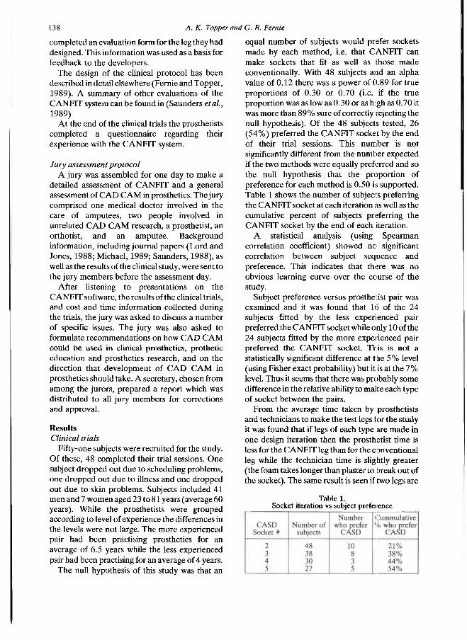
138 A. K. Topperand G. R. Fernie
completed an evaluation form for the leg they had designed. This information was used as a basis for feedback to the developers.
The design of the clinical protocol has been described in detail elsewhere (Fernie and Topper, 1989). A summary of other evaluations of the CANFIT system can be found in (Saunders et al., 1989)
A t the end of the clinical trials the prosthetists completed a questionnaire regarding their experience with the C A N F I T system.
Jury assessment protocol A jury was assembled for one day to make a
detailed assessment of C A N F I T and a general assessment of C A D C A M in prosthetics. The jury comprised one medical doctor involved in the care of amputees, two people involved in unrelated C A D C A M research, a prosthetist, an orthotist, and an amputee. Background information, including journal papers (Lord and Jones, 1988; Michael, 1989; Saunders, 1988), as well as the results of the clinical study, were sent to the jury members before the assessment day.
After listening to presentations on the CANFIT software, the results of the clinical trials, and cost and time information collected during the trials, the jury was asked to discuss a number of specific issues. The jury was also asked to formulate recommendations on how C A D C A M could be used in clinical prosthetics, prothetic education and prosthetics research, and on the direction that development of C A D C A M in prosthetics should take. A secretary, chosen from among the jurors, prepared a report which was distributed to all jury members for corrections and approval.
Results Clinical trials
Fifty-one subjects were recruited for the study. Of these, 48 completed their trial sessions. One subject dropped out due to scheduling problems, one dropped out due to illness and one dropped out due to skin problems. Subjects included 41 men and 7 women aged 23 to 81 years (average 60 years). While the prosthetists were grouped according to level of experience the differences in the levels were not large. The more experienced pair had been practising prosthetics for an average of 6.5 years while the less experienced pair had been practising for an average of 4 years.
The null hypothesis of this study was that an
equal number of subjects would prefer sockets made by each method, i.e. that C A N F I T can make sockets that fit as well as those made conventionally. With 48 subjects and an alpha value of 0.12 there was a power of 0.89 for true proportions of 0.30 or 0.70 (i.e. if the true proportion was as low as 0.30 or as h:gh as 0.70 it was more than 8 9 % sure of correctly rejecting the null hypothesis). Of the 48 subjects tested, 26 ( 5 4 % ) preferred the C A N F I T socket by the end of their trial sessions. This number is not significantly different from the number expected if the two methods were equally preferred and so the null hypothesis that the proportion of preference for each method is 0.50 is supported. Table 1 shows the number of subjects preferring the CANFIT socket at each iteration as well as the cumulative percent of subjects preferring the C A N F I T socket by the end of each iteration.
A statistical analysis (using Spearman correlation coefficient) showed no significant correlation between subject sequence and preference. This indicates that there was no obvious learning curve over the course of the study.
Subject preference versus prosthe :ist pair was examined and it was found that 16 of the 24 subjects fitted by the less experienced pair preferred the CANFIT socket while only 10 of the 24 subjects fitted by the more experienced pair preferred the CANFTT socket. This is not a statistically significant difference at the 5 % level (using Fisher exact probability) but it is at the 7 % level. Thus it seems that there was probably some difference in the relative ability to make each type of socket between the pairs.
From the average time taken by prosthetists and technicians to make the test legs for the study it was found that if legs of each type are made in one design iteration then the prosthetist t ime is less for the CANFIT leg than for the conventional leg while the technician time is slightly greater (the foam takes longer than plaster to break out of the socket). The same result is seen if two legs are
Table 1. Socket iteration vs subject preference

Evaluation of CAD sockets 139
made by each method. If only one or two conventional design attempts are sufficient to produce a properly fitting leg but three or more CANFIT legs must be made, then using the computer method would significantly increase the time required to produce a good leg. It should be noted that in using an iterative fitting process a large component of the increase in time is for the technician to make the trial legs.
Both the subjects and prosthetists comments about the fit of each trial prosthesis were recorded and were used as the basis for feedback to the developers. This feedback resulted in changes in the system such as the added ability to increase and decrease the overall volume using "ply" mode, the ability to lengthen the socket, shaded image display, and the ability to select the location to be changed on the shaded rather than the outline image.
Prosthetist questionnaire All four prosthetists expressed doubts about
the accuracy of the hand held measurement tool. The tape measure part could be tightened by different amounts and the hard plastic part of the tool did not always fit the contour of the anterior portion of the stump despite the available adjustments. All the prosthetists thought that the computer was unable to produce an accurate base shape from the measurements provided and that, due to the use of a limited range of reference shapes, the system worked best for stumps with "ideal" shapes. No allowance was made for stump features such as bowed tibias.
All the prosthetists thought that the shaded view was the most useful of the three possible methods of viewing the socket (outline, wire frame, shaded). A common complaint about the display was that these prosthetists prefer viewing socket shapes aligned vertically on the screen rather than horizontally.
Three of the four prosthetists considered that making modifications was not "easy" but "OK" while the other prosthetist thought that, in general, modifications were difficult to make. Generally length changes, moderate changes in volume and increases or decreases of relief in small areas were considered easy to make. Changes which were difficult to make include large contour changes, changes which are not in the anteroposterior or mediolateral planes, large volume changes, eliminating gaps between the socket and the skin without causing pressure on
surrounding areas, and reducing areas to produce counter pressure. The prosthetists wanted to be able to "draw" modifications rather than manipulate "dots".
The ratings given to the ease of use of the system were spread across the scale from "very easy" to "very difficult". Estimates of the number of fittings required before being able to fit a client ranged from 2-3 to 12. Estimates of the number of fittings required to become a proficient user of the system ranged from 5 to 100.
All the prosthetists said that, if they were allowed to use a soft liner and wool socks to fit the client, on average, a client could be fitted satisfactorily in three iterations (i.e. first socket design plus 2 chances at making modifications) using the CANFIT system.
Three prosthetists thought that the present system is clinically useful in limited cases while the fourth prosthetist did not think it was clinically useful.
It should be noted that in 1990 the measurement method, viewing methods and modification methods are all being revised based on these comments as well as others which the developers have received.
Jury assessment Some of the comments in this summary of the
jury assessment apply specifically to CANFIT but many apply in general to C A D systems for prosthetics.
The system as evaluated could not deal with all forms and severities of unusual anatomy due to a combination of a measurement method which did not seem to collect sufficient information and the subsequent use of standard reference shapes which assume a more or less standard anatomy and allow for limited types of variations. Use of a detailed digitization of the stump, or of a cast of the stump, as a start shape, followed by a set of prosthetist controlled modifications may resolve this problem. The jury favoured the use of a moulded cast of the stump as input to the system so that some information regarding the bone and tissue structure is incorporated into the start shape.
It was agreed that C A N F I T could decrease the time spent designing sockets and that it eliminates plaster drying time. However, other factors militate against amputees realizing the benefits of these time savings. These factors include the
140 A. K. Topperand G. R. Fernie
necessity to reorganize present practices (traditional work scheduling and patient booking), and patient preference (if living close to the prosthetics centre) for a few brief visits rather than one all day visit. If current practices could be reorganized to take advantage of the time savings made possible with CANFIT then the system could provide better service for out-of-town patients who could decrease the length of their stay, children who have little patience, and new amputees who require several fits during the period when their s tump is shrinking.
Practical remote site service would be valuable in the Canadian context because of vast distances. The jury took the view that, because digitizers, vacuum formers and numerically-controlled machining systems are becoming less expensive and are relatively portable, the fitting and fabrication should be incorporated in a mobile unit to service remote sites. The jury could not see any benefit in having only the design part of the system going with the travelling prosthetist. The prosthetist would then have to wait for the leg to be shipped back so that it can be fitted and then would probably have to repeat the process because it is likely that the first socket will not fit properly. The process is not viewed as an improvement over the prosthetist taking a cast and sending that back to the fabrication facility.
Services for the Third World were thought to be realistic only if the costs were fully underwritten by the Canadian government. It was thought however that, in general, this approach does not work on a sustained basis. Practical Third World services, history has taught, should derive from training of local practitioners and the innovative use of local materials and talents with the emphasis on self sufficiency. Both prosthetists and committee members thought that the shape information accumulated by using C A D could eventually lead to some expert criteria for off-the-rack sockets which would raise the present minimum standards.
The jury agreed that a prosthetics facility can increase its profit by increasing the number of legs produced if:— 1. CANFIT could produce a good fitting socket
in the same, or fewer design attempts than the conventional method so that the total time spent by the prosthetists is less than it would be if conventional methods are used, and
2. prosthetics facilities amalgamate so that the facility has more clients per prosthetist and the
time saved by C A N F I T can be used to fit more amputees.
The system that was evaluated was not considered cost effective as it was not able to produce legs which fit as well as the conventional legs in 1 or 2 design attempts. However, the new version of the system which was demonstrated and described, was viewed as potentially profitable. In any case, it was agreed that more clients per prosthetics centre would be necessary to justify such systems. Justification of the system would be easier if it included automated cosmetic cover generation, automated alignment of the limbs, automation of paper work, and packages for spinal braces and footwear fabrication.
Although the system that was evaluated was not deemed appropriate for commercial application, the new version of C A N F I T which was under development at the time of the jury trial seemed as though it might solve many of the problems that were apparent in the study. This new system should be tested in clinical trials to confirm these expectations.
The jury thought that C A D systems for prosthetics are on the brink of being commercially feasible. Although the systems will probably not be profitable tools for another three to five years it may be wise to consider buying a system in the next year or two so that the technology can be integrated gradually. The changeover period will allow clinicians to restructure their practices so that they can take advantage of the strong points of C A D and also allow them to develop a method of screening to determine which clients are suitable for C A D fittings. Jury members also thought that it is important for prosthetists to use these systems in the near future so that they can have input into the development of this technology. Prosthetists who are considering buying a system should plan to try testing the various systems available by fitting an amputee or two before committing themselves to a particular system. The jury advocated that C A N F I T system suppliers be required to allow extensive try-before-buy with real patients in the practitioner's own shop. Prosthetists should be forewarned that in the short run they are likely to lose money by investing in this technology and that their facility must be able to absorb this short term loss. If they do not think they can afford any immediate loss but want to become involved, they should consider sharing C A D resources with other facilities.
Evaluation of CAD sockets İ 4 İ
Because many prosthetists seem to agree that C A D is "the way of the future" for prosthetics, the jury felt that exposure of students to this new technology and related concepts is highly important. In order to prepare students they should be taught the skills they need to use any of these systems, such as three dimensional visualization and typical methods of manipulating objects on a computer, rather than making them experts on a specific system. Although exclusive learning by C A D workstation sessions should be avoided, C A D can still play a role in prosthetics education as long as traditional manual skills and student control of decisions (not computer algorithm-based decision making) are retained.
Discussion The lack of statistical evidence of a learning
curve could be due to the effect of a thorough training course prior to the start of the study. It seems that there was some difference in the relative ability to make each type of socket between the pairs of prosthetists. From observations made during the course of the study, the authors attribute this difference to varying adaptability to the computer rather than to differences in hand skills required in the conventional method.
Some of the responses of the prosthetists to the questionnaire which they completed at the end of the study were somewhat contradictory. While they were very positive about C A D C A M in prosthetics, they were critical of its present status. The prosthetists wanted a more accurate and detailed measurement system and more control over the shape creation process. The shaded display, which was introduced during the course of the study, was thought to be a great improvement over the outline and wire frame displays. Some types of modifications were found to be easy to make, while others were more difficult. Some of the changes which were difficult to make, however, such as large contour and volume changes, might not occur as often if more detailed and accurate (or more pertinent) initial measurements were made.
In order to cope with varying anatomy, the jury recommended that the system should use a detailed digitization of the stump or a cast of the stump as a starting shape. The modifications to this starting shape should be controlled by the prosthetist. The authors agree that the set of reference shapes and types of measurements used
by the system tested did not provide adequate starting shapes and that, while there is a lack of quantitative data regarding socket shapes, other alternatives may be better. There are many problems inherent with such alternatives however. If a moulded cast of the stump is made then some of the benefits of C A D , including time savings and consistency of results (each prosthetist may produce a different moulded cast), are diminished. On the other hand if a passive cast is taken or a non-contacting shape sensor is used then, while many data points are collected, most of the information about the bone structure and tissue characteristics is lost. The jury suggested that the eventual solution to these problems may involve a combination of imaging systems, which provide more information regarding the stump, and software which can use this information to emulate the prosthetist 's moulding techniques to produce appropriate areas of relief and weight bearing. Another possibility is that, as a larger library of reference shapes is built and as more is learned regarding what measurements are necessary to appropriately scale the reference shapes, the use of the reference shape method may become more attractive.
There has been some research into the use of other types of measurements and measurement methods for socket design such as tissue stiffness (Krouskop et al., 1989), ultrasound (Faulkner et al., 1988) and computed tomography (CT) (Faulkner and Walsh, 1989). Krouskop's system combined measurements of tissue stiffness and stump shape to produce a socket shape for above-knee amputees. Faulkner's work with ultrasound resulted only in another method of digitizing surface shape. In Faulkner's work with CT images, below-knee stump shape was measured and then modified by a prosthetist who could view the bone structure while making these changes; no software was developed which integrated the surface and internal anatomy to produce a socket. Faulkner suggested that neither CT nor magnetic resonance (MRI) images are suitable for this application. By viewing the Rehabilitation Research and Development Progress Reports published by the American Department of Veterans Affairs from 1986 to 1989, where much of this work is described, it can be seen that work in the area of alternative measurement techniques seems to have diminished and that most systems use one of the methods previously mentioned
1 4 2 A. K. Topper and G. R. Fernie
(cast digitization or non-contacting shape sensing). Current research in C A D in prosthetics seems to be focused on methods of graphically representing sockets and on the interactive methods used by prosthetists to change the shape. While this work is important, the key questions regarding the underlying methodologies, deserve more study i.e. 1. what are the crucial measurements necessary
to design a socket? (The authors do not believe that a complete description of the stump surface is the solution.)
2. how are these measurements of a stump's characteristics transformed into an appropriate socket shape?
The jury suggested that a remote site service using a mobile clinic with a C A D workstation, a carver and a vacuum former would be beneficial in Canada. There are problems, however, not considered by the jury in suggesting a complete mobile clinic rather than a travelling prosthetist with only a portable design station. These problems include extremely long driving times and many communities that are accessible only by air.
Gradual integration was thought necessary to allow a restructuring of current practices in order to take advantage of the benefits of C A D . This would allow clinicians to become competent and efficient users of the system, and permit a client screening protocol to be developed so that time is not wasted trying to fit amputees not suited to the current C A D technology. Most payback analyses make the assumption that this process happens instantly but there are always growing pains with the introduction of new equipment and new technology.
Conclusion The CANFIT system (in the version tested)
was found, in a controlled single-blind trial, to be capable of fitting below-knee amputees as well as could be achieved with conventional methods. However, more trial fits were required. A jury predicted that the rate of evolution of the system will lead to its profitable application in major centres within 3 to 5 years and recommended prosthetists consider acquiring a system in the next 1 or 2 years in order to facilitate the gradual and orderly introduction to clinical practice.
Acknowledgements This project was funded by Health and Welfare
Canada. The authors would also like to acknowledge the
following:— — the prosthetists involved in the study: Wallis
Farraday, Brian Giavedoni, Bryan Mitchell and Bill Weick,
— the subjects who volunteered their time to participate in the study,
— the staff at the Sunnybrook Centre for Independent Living where the clinical trials were held,
— the members of the Medical Engineering Resources Unit for their cooperation,
— Marco Katic who performed the statistical analysis of the clinical data,
— the members of the Jury: Dan Blocka, Dieter Bochman, James Canney, Tom Ewart, Johann Schmid, and Barbara Whylie.
REFERENCES
FAULKNER, V. W . , WALSH, N . E. (1939). Computer designed prosthetic socket from analysis of computed tomography data. J. Prosthet. and Orthot. 1,154-164.
FAULKNER, V. W . , WALSH, N. E., GALL, H. G . (1988). A computerized ultrasound shape sensing mechanism. Orthot. Prosthet. 41, 57-65.
FERNIE, G . R. , TOPPER, A. K. (1989). Evaluation of CADCAM in prosthetics. In: PAUL, J . P., BARBENEL, J . C., COURTNEY, J . M., KENEDI, R. M. (eds) Progress in Bioengineering, MacMillan, London, pp 193-197.
HOLDEN, J . M , FERNIE, G . R. (1986). Results of the pilot phase of a clinical evaluation of computer aided design of trans-tibial prosthesis sockets. Prosthet. Orthot. Int. 10, 142-148.
KROUSKOP, T. A., MALINAUSKAS, M . , WILLIAMS, J. , BARRY, P.A., MUILENBURG, A. L. , WINNINGHAM, D. J. (1989). A computerized method for the design of above-knee prosthetic sockets. J. Prosthet. Orthot. 1, 131-138.
LORD, M., JONES, D. (1988). Issues and themes in computer aided design for external prosthetics and orthotics. J. Biomed. Eng. 10, 491-495.
MICHAEL, J. W . ( 1 9 8 9 ) . Reflections on CADCAM in prosthetics and orthotics. J. Prosthet. Orthot. 1, 116-121.
SAUNDERS, C. G . (1988). Clinical evaluations of the Canfit CADCAM system (internal report). Vancouver: Medical Engineering Resource Unit, University of British Columbia.
SAUNDERS, C. G . , FOORT, J., BANNON, M., LEAN, D., PANYCH, L . (1985). Computer aided design of prosthetic sockets for below-knee amputees. Prosthet. Orthot. Int. 9, 17-22.
SAUNDERS, C. G. , BANNON, M., SABiSTON, R . , PANYCH, L., JENKS, S. L., WOOD, I. R., RASCHKE, S. (1988). The CANFIT system: shape management technology for prosthetic and orthotic applications. J. Prosthet. Orthot. 1, 122-130.
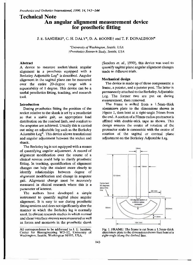
Prosthetics and Orthotics International, 1990, 14, 143—144
Technical Note An angular alignment measurement device
for prosthetic fitting
J. E. SANDERS*, C. H. DALY*, D. A. BOONE† and T. F. DONALDSON*
*University of Washington, Seattle, USA †Prosthetics Research Study, Seattle, USA
Abstract A device to measure socket/shank angular alignment in a prosthesis equipped with a Berkeley Adjustable Leg® is described. Angular alignment in the sagittal plane can be measured over the entire 20-degree range with a repeatability of 1 degree. This device can be a useful prosthetics fitting, teaching, and research tool.
Introduction During prosthetics fitting the position of the
socket relative to the shank is set by a prosthetist so that a stable gait, an appropriate load distribution on the residual limb, and comfort to the amputee are achieved. Usually this is carried out using an adjustable leg such as the Berkeley Adustable Leg®. This device allows translational and angular adjustment between the socket and shank.
The Berkeley leg is not equipped with a means of quantifying angular adjustment. A record of alignment modification over the course of a clinical session could help to clarify prosthetic fitting. In teaching, quantification of alignment changes can help the student more clearly to identify relationships between degree of alignment modification and change in amputee gait. Alignment change must be accurately measured in clinical research where this is a parameter of interest.
The authors have developed a simple instrument to quantify sagittal plane angular alignment. It is easy to use during prosthetic fitting sessions and does not significantly alter the manner in which the Berkeley leg is normally used. In clinical research studies in which normal and shear interface stresses were measured as well as forces and moments in the prosthetic shank
(Sanders et al., 1990), this device was used to quantify sagittal plane angular alignment changes made in different trials.
Mechanical design The device is made up of three components: a
frame, a pointer, and a pointer post. The latter is permanently attached to the Berkeley Adjustable Leg. The former two are put on during measurement, then removed.
The frame is milled from a 1.5mm-thick aluminium plate to the dimensions shown in Figure 1, then bent at a right-angle 54mm from the end. A section of a 50mm-radius protractor is affixed with double-stick tape as shown. This design ensures the centre of rotation of the protractor scale is concentric with the centre of rotation of the sagittal or coronal plane adjustment on the Berkeley Adjustable Leg.
Fig. 1. FRAME: The frame is cut from a 1.5mm-thick aluminium plate to the dimensions shown then bent at a right-angle along the dashed line.
All correspondence to be addressed to J. E. Sanders, Center for Bioengineering WD-12 , University of Washington, Seattle, Washington 98195, U S A .
143
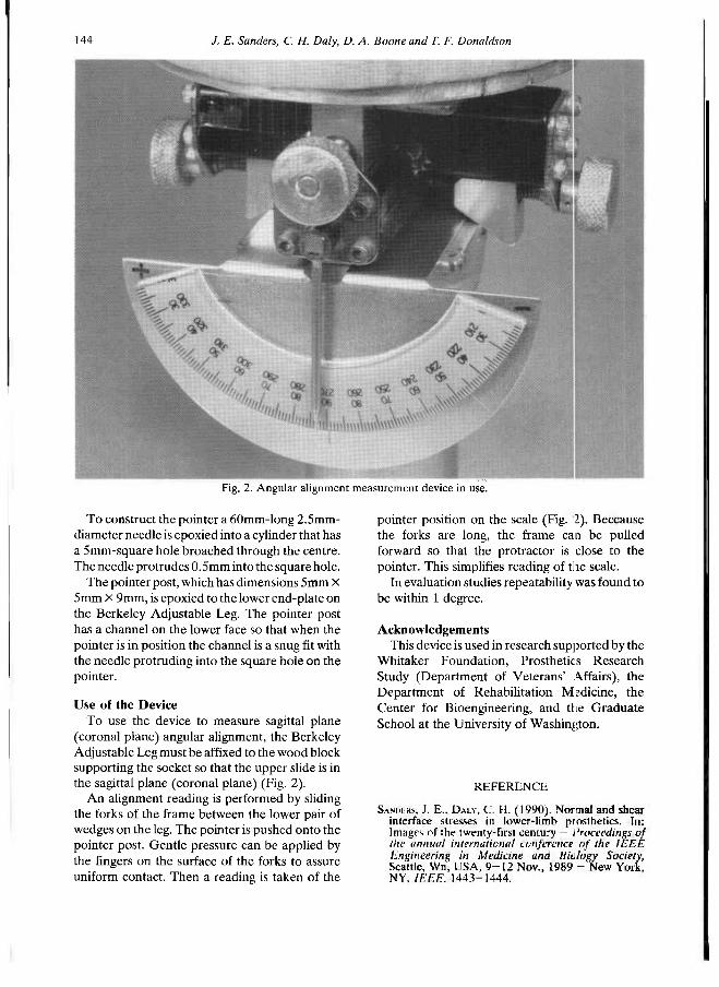
144 /. E. Sanders, C. H. Daly, D. A. Boone and T. F. Donaldson
To construct the pointer a 60mm-long 2.5mm-diameter needle is epoxied into a cylinder that has a 5mm-square hole broached through the centre. The needle protrudes 0.5mm into the square hole.
The pointer post, which has dimensions 5mm X 5mm X 9mm, is epoxied to the lower end-plate on the Berkeley Adjustable Leg. The pointer post has a channel on the lower face so that when the pointer is in position the channel is a snug fit with the needle protruding into the square hole on the pointer.
Use of the Device To use the device to measure sagittal plane
(coronal plane) angular alignment, the Berkeley Adjustable Leg must be affixed to the wood block supporting the socket so that the upper slide is in the sagittal plane (coronal plane) (Fig. 2).
An alignment reading is performed by sliding the forks of the frame between the lower pair of wedges on the leg. The pointer is pushed onto the pointer post. Gentle pressure can be applied by the fingers on the surface of the forks to assure uniform contact. Then a reading is taken of the
pointer position on the scale (Fig. 2). Because the forks are long, the frame can be pulled forward so that the protractor is close to the pointer. This simplifies reading of the scale.
In evaluation studies repeatability was found to be within 1 degree.
Acknowledgements This device is used in research supported by the
Whitaker Foundation, Prosthetics Research Study (Department of Veterans' Affairs), the Department of Rehabilitation Medicine, the Center for Bioengineering, and the Graduate School at the University of Washington.
Fig. 2. Angular alignment measurement device in use.
REFERENCE
SANderS, J . E. , DALY, C. H . ( 1 9 9 0 ) . Normal and shear interface stresses in lower-limb prosthetics. In: Images of the twenty-first century — Proceedings of the annual international conference of the IEEE Engineering in Medicine and Biology Society, Seattle, Wn, USA, 9 - 1 2 Nov., 1 9 8 9 - New York, NY, IEEE, 1 4 4 3 - 1 4 4 4 .
Prosthetics and Orthotics International, 1990, 14, 145
Letter to the Editor
Dear Sir
I was very interested in your editorial to "Prosthetics and Orthotics International Vol. 14, p 53 . I have been involved in looking at rehabilitation resources in certain Islamic countries, which have been involved in long wars in the last decade or so; Afghanistan, Iraq and the Lebanon, which I have visited in the last year.
With the held of ISPO studies, I was able to extrapolate assessments of various categories of disability in each of these countries. Since my extrapolations produced figures five times greater than those of the U N agencies, I got a name for exaggeration. However, no one has been able to prove me wrong, because we are still finding disabled in large numbers, beyond others ' original estimates. I actually got a Minister in one country to agree that my estimate was about right!
Amongst the Afghan refugees, my colleagues and I developed techniques for finding the disabled, of all ages. W e also have trained teams of orthopaedic technicians who can make and fit prostheses and orthoses. This novel training concept is now recognised by I C R C and W H O as a relevant method of giving clinical services whilst expanding training. If anyone is interested, I can expand on it.
Whatever we can devise for the short term, there remains the desperate need for graduate Prosthetist /Orthotists in the big World in which we live. Also, it is a big waste if those who graduate from, say, Strathclyde, merely become lower limb Prosthetists. Out there, they will have to turn their theoretical skills to every need, and some more! A n d hands-on physiotherapy is essential. Until the developed world wakes up to the needs of others the Nor th /Sou th gap is going to continue to accelerate apart, fruitlessly.
Thank you for raising this urgent matter, which is sadly ignored in my country. Incidentally, in those countries that I visited only 2 0 % of all disabled have reasonable rehabilitation resources available to them. Isn't it about time we stopped fighting to repair the human damage already done?
Yours sincerely
Philip Dixon Chairman of the Council World Veterans Foundation
1 Forest Road Kew Richmond Surrey T W 9 3BY UK
145
Prosthetics and Orthotics International, 1990, 14, 146—147
International Newsletter Winter 1990
The ISPO Executive Board is preparing a document which lists all ISPO members who are active in National or International Standards Committees on prosthetics and orthotics and rehabilitation engineering subjects related to our field. The Executive Board would therefore be grateful to receive information from individual members who participate in national and international standards meetings. Information should be sent to the Honorary Secretary:
Norman A . Jacobs National Centre for Training and Education in Prosthetics and Orthotics University of Strathclyde Curran Building 131 St. James Road Glasgow, Scotland, U K Conferences, present and future, dominate news from several of ISPO's national member societies.
Across the globe, ISPO members are engaging in professional activities designed to expand rehabilitation for individuals with physical disabilities.
Thailand National Member Society announced the Combined Meeting of the Asian Orthopaedic Society, celebrating its 10th Congress, and the Thai Orthopaedic Association held in October 1990 in Jomtien, Pattaya, Thailand. Direk Israngkul, MD, Meeting Chairman, noted that Mahidol University is cosponsoring the programme. ISPO Executive Board member Dr. Thamrongrat Keokarn is the Honorary Chairman. The Congress rotates yearly through Indonesia, Malaysia, Phillipines, Singapore, and Thailand. The meeting featured scientific papers and posters, as well as a trade exhibition supported by medical and surgical manufacturers, pharmaceutical companies, and scientific booksellers. A n international roster of guest speakers includes those from Canada, Germany, Japan, Switzerland, and the United States.
Netherlands National Member Society is sponsoring a series of multidisciplinary practical courses. Topics include orthotics, transfers and lifting, and legal problems in rehabilitation. Tentative plans for 1991 include courses on amputation and prostheses for the lower limb, ischial containmen: above-knee prosthetic sockets, neuropathology, and biomechanics. In April 1991, the society will participate in a minicongress at the University of East Anglia, Norwich, England. Prominent papers are those on Management of the Elderly Amputee by Prof. dr. J. de Vries, Orthopedic Footwear by J. Hanssen, Orthotics for Spinal Cord Indury by Dr. J. H. C. Vorsteveld, and C A D / C A M by Ir. B. Nienhuis.
Australian National Member Society concluded its Annual Scientific Meeting in conjunction with the Department of Veterans ' Affairs in Brisbane. Overseas speakers were Professor Gordon Hunter , Canada who discussed surgery and prosthetic fitting of the upper-limb amputee, as well as psychological problems leading to amputation and reamputation; Garth Johnson, PhD, England who presented his work on the shock meter, an instrument for assessing shock absorbing footwear in running and walking, and measurement of shoulder movement; Mr. Arthur Beasley, ISPO Chairman, New Zealand who outlined early management of the amputee; and Wallace Farraday, Canada who compared C A D / C A M sockets. Current officers are Dr. Adrian von der Borch, Chairman; Dr. George Carter, Vice Chairman; Valma Angliss, Honorary Secretary; Martin Masson, Honorary Treasurer; and Committee Membei s Belle Davis, Dr. W. G. Doig, Jane Griffith, Jean Halcrow, and Michael O'Toole. Society member Bill Contayannis completed a work-study visit to the United States recently, and Dr. Robert Klein presented a paper at the 9th Asia and Pacific Regional Conference of Rehabilitation International in Beijing, China. I n conjunction with the Department of Veterans ' Affairs, ISPO will repeat its successful 5 day postgraduate course in Upper Extremity Prosthetics; the course is scheduled for May 1991 and is accredited by the Australian Congress' of Rehabilitation Medicine. ISPO member Dr. Bob Oakshott succeeded in securing the agreement that the 1995 meeting of the International Federation of Physical and Rehabilitation Medicine will meet in Sydney.
146
International Newsletter 147
United Kingdom National Member Society reported its membership is the highest ever and its scientific meeting in Edinburgh, under the guidance of Brendan McHugh, attracted a record attendance. The B L E S M A prizes for the two best papers at the annual scientific meeting were awarded to Raj iv Hanspal for his paper, " Cognitive and Psychomotor Assessment in Prosthetic Rehabilitation of the Elderly ", and A. B. C. Smith for "Development of an Ischial Pressure Relief System Using Functional Electrical Stimulation for the Prevention of Pressure Sores in Quadriplegics". David Simpson has compiled a register of establishments involved with research, development and evaluation of equipment, and Barry Meadows is completing a register of gait laboratories. Current society officers are Mr. J. C. Peacock, Chairman; Mr. R. A. Cooper, Vice Chairman; Dr. R. G. S. Platts, Honorary Secretary; and Mr. C. Dunham, Honorary Treasurer and Membership Secretary. The Executive Committee consists of Mr. D. N. Condie, Ms. B. Davis, Dr. M. Dewar, Dr. B. F. McHugh, Dr. C. B. Meadows, Mr. R. Nelham, Dr. R. G. Redhead, Mr. D. Simpson, Dr. C. P. U. Stewart, and Dr. D. J. Thornberry. Professors G. Murdoch and J. Hughes and Mr. N. A. Jacobs are ex officio members.
United States National Member Society has formed an ad hoc committee on brachial plexus injury and treatment, under the leadership of Executive Board member T. Walley Williams who is working with Director Diane Atkins and Secretary Michael Schuch to develop a seminar on the topic. John Craig is the new chairman of the Committee on Prosthetics and Orthotics in Developing Countries; his appointment follows the very successful conference of the Central American Association for Educational Advancement of Orthotists, Prosthetists, and Rehabilitation Professionals which he facilitated. Executive Board member Bruce McClellan is the chairman of the programme committee and is organizing the annual ISPO programme to be held in conjunction with the annual meeting of the American Academy of Orthotists and Prosthetists in March 1991. The society attracted considerable attention to the 1992 World Congress by means of its exhibit at the national assembly of the American Orthotics and Prosthetics Association. US ISPO supported the Americans with Disabilities Act which was recently passed by Congress; the law guarantees employment and housing opportunities for individuals with disabilities. Chairman Maurice LeBlanc represented the society at Invaltech 90 in Moscow where he signed an agreement with Soviet authorities proposing future cooperation and training efforts.
Joan E. Edelstein, Editor
Prosthetics and Orthotics International, 1990, 14, 148
The Brian Blatchford Prize The Brian Blatchford Prize has been established by the Blatchford Family to honour th s memory
of Brian Blatchford. It is awarded every three years at the World Congress of the International Society for Prosthetics and Orthotics.
The next Prize will be awarded at the Seventh World Congress ISPO to be held in Chicago, U S A from 28th June — 3rd July, 1992. O n this occasion the Prize will be £2,200 and will be awa rded for a recent outstanding innovation in prosthetics a n d / o r orthotics practice. The innovation should be related to a piece of prosthetic a n d / o r orthotic hardware, or a scientifically based new technique which results in a better prosthesis or orthosis. The innovation should have reached a sufficiently advanced stage to ensure that it can be used successfully on patients.
The applicant or nominator should initially present evidence detailing the innovation, together with a sample of the device if appropriate, and send it to reach the President of ISPO by 1st November 1991 at the following address:
Professor W. H. Eisma Elswout 2 9301 TS Roden The Netherlands
The innovation shall be presented at the Seventh World Congress and duly published in Prosthetics and Orthotics International.
The President and Executive Board of the International Society for Prosthetics and Orthotics and the Blatchford family reserve the right to withhold the Prize should no suitable applicant be submitted.
The Forchheimer Prize The Forchheimer Prize has been established by the Forchheimer family to honour the memory of
Alfred Forchheimer. It is awarded every three years at the World Congress of the International Society for Prosthetics and Orthotics.
The next Prize will be awarded at the Seventh World Congress of ISPO to be held ir Chicago, U S A from 28th June - 3rd July, 1992 for the most outstanding paper on Objective Clinical Assessment, Clinical Evaluation, or Clinical Measurement published in Prosthetics and Orthotics International during the three years prior to the Congress.
The President and Executive Board of the International Society for Prosthetics and Orthotics and the Forchheimer family reserve the right to withhold the Prize should no suitable paper be published.
148
Prosthetics and Orthotics International, 1990, 14, 149—153
Calendar of Events National Centre for Training and Education in Prosthetics and Orthotics
Short Term Courses and Seminars 1991
Courses for Physicians, Surgeons and Therapists
NC502 Upper Limb Prosthetics and Orthotics; 7-11 January, 1991. NC505 Lower Limb Prosthetics; 14-18 January, 1991. NC511 Clinical Gait Analysis; 6-8 February, 1991. NC503 Introductory Biomechanics; 25 February-1 March, 1991. NC510 Wheelchairs and Seatings; 5-7 March, 1991.
Courses for Prosthetists
NC211 PTB Prosthetics; 11-22 February, 1991. NC212 Hip Disarticulation Prostheses; 22 April-3 May, 1991. NC218 The Ischial Containment Above-Knee Socket; 13-17 May, 1991.
Course for Orthotists
NC202 Knee-Ankle-Foot Orthotics; 15-19 April, 1991.
Course for Orthotists and Therapists
NC217 Ankle-Foot Orthoses for the Management of the Cerebral Palsied Child; 13-15 March, 1991.
Course for Rehabilitation Engineers
NC801 A n Appreciation of C A D C A M Technology; 4-6 June; 1991.
Seminar
NC719 C A D C A M ; 7 June, 1991.
Further information may be obtained by contacting Prof. J. Hughes, Director, National Centre for Training and Education in Prosthetics and Orthotics, University of Strathclyde, Curran Building, 131 St. James ' Road, Glasgow G 4 0LS, Scotland. Tel: 041-552 4400 ext. 3298.
Northwestern University Medical School Short Term Courses 1991
Courses for Physicians
603 C Lower and Upper Limb Prosthetics; 25 February-1 March, 1991. 703 B Spinal, Upper and Lower Limb Orthotics; 8-12 April, 1991. 603 D Lower and Upper Limb Prosthetics; 22-26 April, 1991 723 B Upper and Lower Limb Orthotics and Prosthetics; 6-10 May, 1991.
Further information may be obtained by contacting Michael D . Brncick, Director, Prosthetic-Orthotic Center, Northwestern University Medical School, 345 E. Superior Street, 17th Floor, Chicago, Illinois 60611-4496, USA. Tel: (312) 908-8006.
149
150 Calendar of events
New York University Medical School Short Term Courses 1991
Courses for Physicians and Surgeons
741 B Lower Limb Prosthetics; 11-15 February, 1991. 751 B Lower Limb and Spinal Orthotics; 25 February-1 March, 1991. 744 A Upper Limb Prosthetics and Orthotics; 18-22 March, 1991. 741 C Lower Limb Prosthetics; 22-26 April, 1991 . 751 C Lower Limb and Spinal Orthotics; 29 April-3 May, 1991. 754 A Foot Orthotics; 16-17 May, 1991.
Courses for Therapists
742 B Lower Limb Prosthetics; 11-15 February, 1991. 752 B Lower Limb and Spinal Orthotics; 25 February-1 March, 1991. 745 A Upper Limb Prosthetics and Orthotics; 18-22 March, 1991. 742 C Lower Limb Prosthetics; 22-26 April. 1991. 752 C Lower Limb and Spinal Orthotics; 29 April-3 May, 1991. 754 A Foot Orthotics; 16-17 May, 1991.
Further information may be obtained by contacting Ms. Sandy Kern, Registrar, Prosthetics and Orthotics, New York University Post-Graduate Medical School, 317 E.34th St., New Yoik, NY 10016, USA. Tel: (212) 340-6686.
31 January-3 February, 1991 Combined Sections Meeting of the American Physical Therapy Association, Anaheim, USA. Information: Information Dept., A P T A , 1111 N.Fairfax St., Alexandria, Virginia 22314, USA.
17-20 February, 1991 1st European Conference on Biomedical Engineering, Nice, France. Information: SEPFI, 8 Rue de la Michodiere, F-75002 Paris, France.
7-12 March, 1991 Annual Meeting of the American Academy of Orthopaedic Surgeons, Anaheim, USA. Information: A A O S , 222 South Prospect, Park Ridge, IL 60068, USA.
19-24 March, 1991 A O P A Annual Meeting and Scientific Symposium, San Diego, USA. Information: A O P A , 717 Pendleton St., Alexandria, V A 22314, USA.
8-10 April, 1991 American Spinal Injuries Association Annual Meeting, Seattle, U S A . Information: Lesley M. Hudson, 2020 Peachtree Rd. NW, Atlanta G A 30309, USA.
10-12 April, 1991 ISPO (UK) Annual Scientific Meeting in collaboration with ISPO (Netherlands), Norwich, UK. Information: Brendan McHugh, N C T E P O , University of Strathclyde, Curran Building, 131 St. James Rd., Glasgow G 4 0LS, Scotland.
Calendar of events 151
10-12 April, 1991 Touch the Future, 3rd South East Regional Conference, Atlanta, USA. Information: Carolyn W. Watkins, Program Chair, 2361-C Henry Clower Blvd., Snellville, G A 30278, USA.
12-13 April, 1991 28th Rocky Mountain Bioengineering Symposium, Rochester, USA. Information: David Carlson, Biomedical Engineering, Iowa State University, Ames, Iowa 50011 , USA.
14-17 April, 1991 11th Annual Scientific Meeting of the Australian College of Rehabilitation Medicine, Perth, Australia. Information: Mrs. A. Worden, Australian College of Rehabilitation Medicine, 55 Charles St., Ryde, N.S.W. 2112, Australia.
5-9 May, 1991 4th International Pre-Prosthetic Surgery Conference, Adelaide, Australia. Information: Multinational Meetings Information Service, BV, J. W. Brouwersplein 27, P O Box 5090, 1007 Amsterdam, Netherlands.
8-12 May, 1991 Orthopaedic and Rehabilitation Technology Trade Fair and Congress, Berlin, Germany. Information: A M K Berlin Ausstellungs-Messe-Kongress-GmbH, Messedamm, 22, D-1000 Berlin 19, Germany.
20-23 May, 1991 ISPO Course on Lower Limb Amputat ions and Related Prosthetics, Port el Kantaoui, Tunisia. Information: ISPO, Borgervaenget 5, DK-2100, Copenhagen 0 , Denmark.
26-29 May, 1991 5th Canadian Congress of Rehabilitation, Prince Edward Island, Canada. Information: Congress Secretariat, C R C D , 45 Sheppard Ave.E. , Suite 8 0 1 , Toronto, Ontario M2N 5W9, Canada.
3-6 June, 1991 American Orthopaedic Association Annual Meeting, Palm Beach, USA. Information: A O A , 222 S.Prospect Ave., Park Ridge, IL 60068, U S A .
10-13 June, 1991 ISPO Scientific Seminar on Clinical Biomechanics of Foot and Shoe, Jönköping, Sweden. Information: Secretariat of ISPO Scientific Seminar, Ulla-Britt Johansson, Dept. of Biomechanics and Orthopedic Technology, University College of Health and Care, P.O. Box 1038, S-551 11 Jönköping, Sweden.
21-26 June, 1991 14th Annual R E S N A Conference, Kansas City, USA. Information: Susan Leone, R E S N A , 1101 Connecticut Ave. NW, Suite 700, Washington D C 20036, USA.
23-27 June, 1991 Annual Conference of the American Physical Therapy Association, Boston, USA. Information: Information Dept., A P T A , 1111 N. Fairfax St., Alexandria, V A 22314, USA.

152 Calendar of events
7-12 July, 1991 16th International Conference on Medical and Biological Engineering, Kyoto, Japan. Information: Dr. O. Z. Roy, IFMBE, c / o National Research Council of Canada, R o o m 164, Bldg. M50, Ottawa, Ontario, K 1 A 0R8 , Canada.
28-31 July, 1991 International Symposium on 3D Analysis of Human Movement, Montreal, Canada. Information: 3D Analysis Symposium, Lab. d 'Etude du Mouvement, Centre de Recherce Pediatrique, Hôpital Saint-Justine, 3175 Cote Ste-Catherine, Montreal, Quebec H 3 T 1C5, Canada.
28 July-2 August, 1991 11th Congress of the World Confederation for Physical Therapy, London, England. Information: Secretariat, WCPT, Conference Associates, 27A Medway St., London SW1P 2BD, England.
5-7 August, 1991 4th European Congress on Research in Rehabilitation, Ljubljana, Yugoslavia. Information: Crt Marincek, University Rehabilitation Institute, Linhartova 5 1 , 61000 Ljubljana, Yugoslavia.
7-11 August, 1991 Southern Orthopaedic Association Meeting, Colorado Springs, USA. Information: SOA, 222 S. Prospect Ave. , Park Ridge, IL 60068, USA.
9-15 August, 1991 3rd International Abilympics, Hong Kong. Information: D. Lynn Abels, 3rd International Abilympics Secretariat, 1st Floor, 57 Wynclham St., Central, Hong Kong.
6-8 September, 1991 2nd Scientific Meeting of the Scandinavian Medical Society of Paraplegia, Copenhagen, Denmark. Information: Centre for Spinal Cord Injured, Rigshospitalet, TH2002 , Blegdamsvej 9, DK-2100 Copenhagen, Denmark.
16-20 September, 1991 Dundee '91-International Conference and Instructional Course on Orthotics, Dundee , Scotland. Information: Dundee '91 Secretariat, c / o Dundee Limb Fitting Centre, 133 Queen St., BrDughty Ferry, Dundee, Scotland.
24-26 September, 1991 Biological Engineering Society Annual Scientific Meeting, Birmingham, England. Information: Mrs. B. Freeman, BES, RCS, 35 Lincoln's Fields, London W 2 3RX, England.
1-6 October, 1991 American Orthotic and Prosthetic Association Annual National Assembly, California, USA. Information: A O P A , 717 Pendelton St., Alexandria, V A 22314, USA.
13-16 October, 1991 7th International Conference on Mechanics in Medicine and Biology, Ljubljana, Yugoslavia. Information: ICMMB 9 1 , Technical Organiser, C A N K A R J E V D O M , Cultural and Congress Centre, Kidricev Park 1, 61000 Ljubljana, Yugoslavia.
Calendar of events 153
21-23 October , 1991 Combined meeting of the Orthopaedic Research Societies of U S A , Japan and Canada, Alberta, Canada. Information: Mrs. M. Aldridge, Conference Office, University of Calgary, 2500 University Drive N.W., Calgary, Alberta T2N INR, Canada.
23-27 October , 1991 Reha '91-Rehabilitation Aids for Handicapped Persons, Düsseldorf, Germany. Information: Reha '91 Press Office, Eva Rugenstein, Messe Dusseldorf, Germany.
31 Oc tober -3 November , 1991 13th Annual Meeting of I E E E Engineering in Medicine and Biology Society, Orlando, USA. Information: Professor Joachim Nagel, Dept. of Biomedical Engineering, Research Centre, University of Miami, P O Box 248294, Coral Gables, FL 33124, USA.
9-13 December , 1991 13th International Conference on Biomechanics., Perth, Australia. Information: 13th ISB Congress Secretariat, Dept . of Human Movement, Univ. of Western Australia, Nedlands W A 6009, Australia.
1992 31 January -2 February, 1992 International Congress and Workshop of the German Society of Orthopedics and Traumatology on the Thumb and Wrist, Düsseldorf, Germany. Information: Dr. C. L. Jantea, Sec. Hand Surgery and Rheumatology, Orthopaedic Dept. of the Heinrich Heine University, Moorenstr. 5, D-4000 Düsseldorf, Germany.
20-25 February, 1992 Annual Meeting of the American Academy of Orthopaedic Surgeons, Washington, USA. Information: A A O S , 222 South Prospect, Park Ridge, IL 60068, U S A .
7-12 Apri l , 1992 American Academy of Orthotists and Prosthetists Annua l Meeting and Scientific Symposium, Miami, USA.
Information: A A O P , 717 Pendleton St., Alexandria, V A 22314, USA.
28 June -3 July, 1992 7th World Congress of ISPO, Chicago, USA. Information: 7th World Congress of ISPO, Moorevents, Inc., 400 North Michigan Avenue, Suite 2300, Chicago, IL 60611 , USA. 26-31 October , 1992 American Orthotic and Prosthetic Association Annual National Assembly, Orlando, USA. Information: A O P A , 717 Pendleton St., Alexandria, V A 22314, USA.

SPONSORING MEMBERS We are pleased to announce that the following organizations were Sponsoring Members of
ISPO for the year 1990.
Camp Scandinavia A / S Vallensbækvej 22 B 2605 Brøndby D E N M A R K
LIC Care Limited Unit B l l , Armstrong Hall Southwood Summit Centre Farnborough, Hants G U 1 4 ONE U.K.
The New Zealand Artificial Limb Board P.O. Box 7281 Wellington South N E W Z E A L A N D
Remploy Limited Medical Products Division Russ Street Board Plain Bristol BS2 0HJ U.K.
Society and Home for the Disabled S A H V A Borgervænget 7 2100 Copenhagen 0 D E N M A R K
Hugh Steeper Limited 234-239 Roehampton Lane London SW15 4LB U.K.
Vessa Limited Paper Mill Lane Alton, Hants G U 3 4 2PY U.K.
War Amputations of Canada 2827 Riverside Drive Ottawa, Ontario K1V O C 4 C A N A D A
New ISPO Publication
C A D CAM in Prosthetics and Orthotics
Report of an ISPO Workshop, Seattle, U.S.A. Edited by R. M. Davies, R. G. Donovan, R. W. Spiers. Published 1989.
Price: ISPO Members $25 (US) (including surface mailing) Non-Members $40 (US)
Orders, which must be accompanied by the appropriate remittance (cheque or international bank draft made payable to ISPO), should be sent to:
Mrs. A . A. I^rsson ISPO Borgervænget 5 2100 Copenhagen 0 D E N M A R K
1 5 4
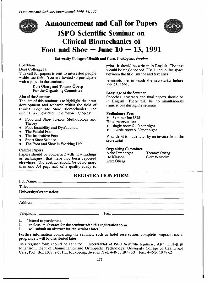
Announcement and Call for Papers ISPO Scientific Seminar on
Clinical Biomechanics of Foot and Shoe - June 10 - 13, 1991
University College of Health and Care, Jönköping, Sweden
Prosthetics and Orthotics International, 1990, 14, 155
Invitation Dear Colleagues, This call for papers is sent to interested people within the field. Y o u are invited t o participate with a paper in the seminar.
Kurt Öberg and Tommy Öberg For the Organising Commit tee
Aim of the Seminar The aim of this seminar is to highlight the latest development and research within the field of Clinical Foot and Shoe Biomechanics. The seminar is subdivided in the following topics:
• Foot and Shoe Science Methodology and Theory
• Foot Instability and Dysfunction • The Painful Foot • The Insensitive Foot • Sport Shoe Science • The Foot and Shoe in Working Life
Call for Papers Papers should be concerned with new findings or techniques, that have not been repor ted elsewhere. The abstract should be of no more than one A 4 page and of a quality ready to
print . It should be written in English. The text should be single spaced. Use 1 and V2 line space between the title, author and text lines.
Abstracts are to reach the secretariat before Feb 28, 1991.
Language of the Seminar Speeches, abstracts and final papers should be in English. There will be no simultaneous translations during the seminar.
Preliminary Fees • Seminar fee $325 Hotel reservation: • single room $110 per night • double room $130 per night
Final debit is made later by an invoice from the secretariat.
Organising Committee Acke Jemberger Tommy Oberg Bo Klasson Ger t Walhelm Kurt Öberg
REGISTRATION FORM Full Name: . . Title: University/Organisation:
Address:
Telephone: Fax:
• I intend to participate. D I enclose an abstract for the seminar with this registration form. D I will submit an abstract for the seminar later.
Fur ther information concerning the seminar, such as hotel reservation, complete program, social program etc will be distributed later.
This register form should be sent to : Secretariat of ISPO Scientific Seminar, At tn : Ulla-Britt Johansson, Dept of Biomechanics and Orthopedic Technology, University College of Heal th and Care , P . O . Box 1038, S-551 11 Jönköping, Sweden, Tel . + 4 6 36 10 47 53 Fax. + 4 6 36 10 47 62
155
Prosthetics and Orthotics International, 1990, 14, 156—158
Seventh World Congress 28 June-3 July, 1992, Chicago, Illinois, USA
A n Invitation We, of the U S A Member Society, cordially invite you to Chicago for the Seventh World Congress of the International Society for Prosthetics and Orthotics ( ISPO). We are pleased that ISPO has selected North America for the Seventh World Congress and look forward to your attendance and participation.
The theme of the 1992 Congress is, "Find the New World of Prosthetics and Orthotics Developing Around the Globe." This theme acknowledges the past and the 500th anniversary of Columbus ' voyage to the Americas, but more importantly it directs us to the future and to the new world of prosthetics and orthotics that people are developing around the globe. These people will be coming to Chicago to share their new knowledge, new developments, and new visions. We hope you will join them.
Chicago is a major medical centre of the USA, with strong traditions in rehabilitation and orthopaedics, and with well-known educational, clinical, and research programmes in prosthetics, orthotics, and rehabilitation engineering. Chicago is a vigorous and enjoyable city — a city of working people from all over the globe. W e think you will enjoy the culture, beauty, diversity, and friendliness of this midwestern city by Lake Michigan. The Illini Indians called this place "Che-ca-gou" for the "wild onions" that grew along the river where it entered the lake. The first Europeans, Pere Jacques Marquette and Louis Joliet, arrived in 1673 and used Chicago as a portage at this continental divide of waterways. The city remains a transportation centre. It is accessible and waiting for you. Mark your calendars and plan a new voyage to find a new world of prosthetics and orthotics.
Dudley S. Childress, Ph.D. General Secretary, Seventh World Congress
Maurice LeBlanc, M.E. , C P . Chairman, US National Member Society of ISPO
Programme The ISPO Seventh World Congress will consist of scientific, technical, clinical, and surgical papers; plenary sessions; instructional courses; scientific and commercial exhibits; poster sessions; a video and film programme; and technical tours. The Rehabilitation Institute of Chicago, near the site of the Congress, will host an "open house" where
participants can also visit Northwestern University's Prosthetic-Orthotic Education Programme, the Prosthetics Research Laboratory, and the Rehabilitation Engineering Centre in Prosthetics and Orthotics.
A social programme and accompanying persons programme is planned so that you will find it easy to experience Chicago's outstanding architecture, parks, boat cruises, swimming and beaches. Plan to take part in the Independence Day celebration with a concert and fireworks on the evening of July 3 and with festivities on the 4th of July. Extend your stay with post-conference tours to the Grand Canyon, Canadian Rockies, or cities such as Washington, D.C.; San Francisco; or New Orleans. Chicago has direct flights to most points in North America.
Topics Amputat ion & Surgical Procedures * Biomechanics: Modeling of Human Movement, Tissue * Consumer Viewpoints * C A D / C A M * Education * Footwear & Foot Problems * Management of Children * Orthotic Management of Fracture * Gait Analysis: Clinical, Research, Instrumentation * Historical & Cultural Issues * Locomotion Aids such as FES, Crutches, and others * Lower and Upper Limb Orthotics/Prosthetics * Materials * Patient Management * Recreation * Rehabilitation in Developing Areas * Seating, P3sitioning, & Wheelchairs * Spine Management & Spinal Orthotics * Testing & Standards * Physical/ Occupational Therapy
General Information
Dates: 28 J u n e - 3 July, 1992
Location: Hyatt Regency Chicago Hotel 151 East Wacker Drive Chicago, IL 60611 U S A
Located in one of the USA ' s largest urban developments, the Illinois Center, the Hyatt is on the south bank of the Chicago Fiver near the Michigan Avenue bridge. It is near (he heart of the city, within easy walking distance of the Loop, North Michigan Avenue, Grant P irk, and Lake Michigan; and close to many museums, shopping areas, restaurants, points of interest, and public transportation. The Hyatt Regency is accessible
156
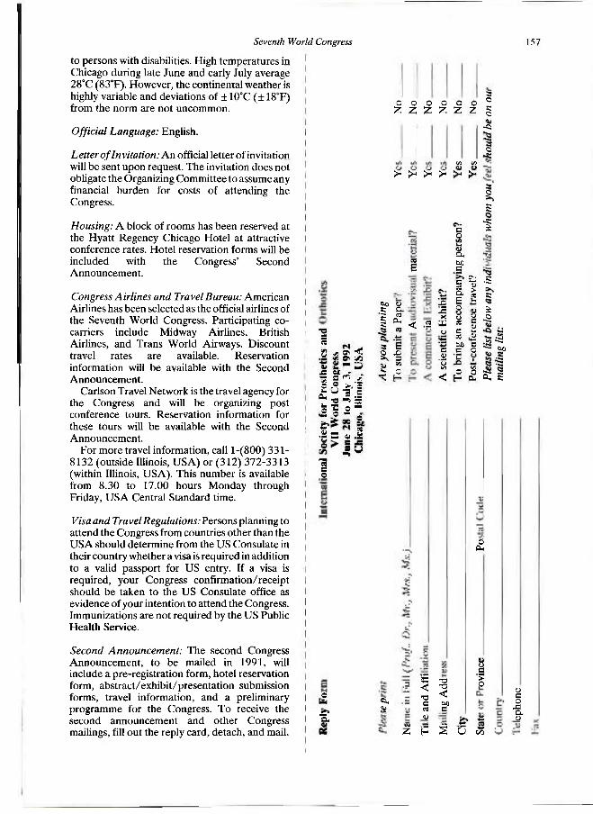
Seventh World Congress 157
to persons with disabilities. High temperatures in Chicago during late June and early July average 28°C (83°F). However, the continental weather is highly variable and deviations of ± 10°C (± 18T) from the norm are not uncommon.
Official Language: English.
Letter of In vitation: A n official letter of invitation will be sent upon request. The invitation does not obligate the Organizing Committee to assume any financial burden for costs of attending the Congress.
Housing: A block of rooms has been reserved at the Hyatt Regency Chicago Hotel at attractive conference rates. Hotel reservation forms will be included with the Congress' Second Announcement .
Congress Airlines and Travel Bureau: American Airlines has been selected as the official airlines of the Seventh World Congress. Participating co-carriers include Midway Airlines, British Airlines, and Trans World Airways. Discount travel rates are available. Reservation information will be available with the Second Announcement .
Carlson Travel Network is the travel agency for the Congress and will be organizing post conference tours. Reservation information for these tours will be available with the Second Announcement .
For more travel information, call l - (800) 3 3 1 -8132 (outside Illinois, U S A ) or (312) 372-3313 (within Illinois, USA) . This number is available from 8.30 to 17.00 hours Monday through Friday, U S A Central Standard time.
Visa and Travel Regulations: Persons planning to attend the Congress from countries other than the U S A should determine from the US Consulate in their country whether a visa is required in addition to a valid passport for US entry. If a visa is required, your Congress confirmation/receipt should be taken to the US Consulate office as evidence of your intention to attend the Congress. Immunizations are not required by the US Public Health Service.
Second Announcement: The second Congress Announcement , to be mailed in 1991, will include a pre-registration form, hotel reservation form, abstract/exhibit /presentat ion submission forms, travel information, and a preliminary programme for the Congress. To receive the second announcement and other Congress mailings, fill out the reply card, detach, and mail.
— İ u * s ä!
J= e x -
! İ İİ I S f l s i s " I S3 * S
"a c o
o
"S.
o o o o Z Z Z Z
>H JH >H >-
o o T. 2
3 O
a o
•es
O VI VI
00 1) Si c St M 1 &
9 3
c
E
< a
e 0
i-O , M C
—•
pan
avel
le HI ~
'£ Z-X Ö •~>
x IB cr
u .ill
İ as a e _ 3
a " L .
'tj VI vi < o ~ \'n
o
£ 1
•S c
≥ -2
Co -HS
~» 60
δ; s
a. tu
se < T3 C M U
-a -α < DO a
o CL,
ü c > o
Z H S U t/3
<U c o J 3 OH U
Seventh World Congress
Congress Secretariat: Moorevents, Incorporated is acting as the Congress Secretariat. Should you have any questions or need additional information, please contact:
Moorevents, Inc. 400 North Michigan Avenue
Suite 2300 Chicago, IL 60611 U S A Phone (312) 644-5997
Fax (312) 644-7591
International Congress Committee M. Stills (USA) , Chairman
G. Murdoch (UK) J. S. Jensen (Denmark)
^ ^ E. Lyquist (Denmark) ^ m g Ä ft S. Sawamura (Japan i ^ m . O © w - H - Eisma (Netherlands), Éx-officio β m ^ h i 2 2 N. A. Jacobs (UK), Ex-officio CN(W ^ S 3- J. Van Rolleghem (Belgium), I H T E R B O R
»̂ ffi Congress Steering Committee ^ S g y 5S Diane Atkins (USA)
h ^ Û Ernest Burgess (USA) g ^ * Joan Edelstein (USA)
N N S* Lawrence Friedmann (L S A ) & B a Jack Hendrickson, Jr. (USA) 5 . . (*"5 Ian Horen (USA)
Qfβ Q Maurice LeBlanc (USA) g ; J. A. Malone (USA)
(JQ John Michael (USA' i 3 Morris Milner (CAN)
£j S Robert Scott (CAN Ni 5» Rami Seliktar (USA)
g ô Ron Speirs (USA) g S s Mel Stills (USA) fD M Robert Tooms (USA)
5 3 Yeongchi Wu (USA)

Prosthetics and Orthotics International, 1990, 14, 159—161
Prosthetics and Orthotics International Index to Volume 14, 1990
Author Index
Alaranta H., Kärkkäinen M. and Pohjolainen T. (See Pohjolainen T.)
Baker P. A . and Hewison S. R. Gait recovery pattern of unilateral lower limb amputees during rehabilitation. 80
Bierling-Sβrensen F., Ryde H., Bojsen-Møller F. and Lyquist E. Shock absorbing material on the shoes of long leg braces for paraplegic walking. 27
Bojsen-Møller F., Bierling-Sørensen F., Ryde H. and Lyquist, E. (See Bierling-Sørensen F.) Boone D . A . , Sanders J. E., Daly C. H. and Donaldson T. F. (See Sanders J. E.)
Daly C. H., Sanders J. E., Boone D . A . and Donaldson T. F. (See Sanders J. E.) De Vries J., Van Jaarsveld H. W. L. and Grootenboer H. J. (See Van Jaarsveld H. W. L. 1 ) D e Vries J., Van Jaarsveld H. W. L., Grootenboer H. J. and Koopman H. F. J. M. (See
Van Jaarsveld H. W. L. 2 ) Dixon P. Letter to the Editor. Donaldson T. F., Sanders J. E., Daly C. H. and Boone D . A . (See Sanders J. E.) 145
Edelstein J. International Newsletter. 45 , 87, 146
Femie G. R. and Topper A . K. (See Topper A. K.) Franceschi F., Loro A. , Mosha E. C. P. and Samwel J. (See Loro A.) Fyfe N . C. M. A n audit of amputation levels in patients referred for prosthetic rehabilitation. 67
Gordon L., Meadows C. B., Stallard J., Wright D. , Major R. E. and Jones N . (See Meadows C. B.)
Grootenboer H. J., Van Jaarsveld H. W. L. and D e Vries J. (See Van Jaarsveld H. W. L. 1 ) Grootenboer H. J., Van Jaarsveld H. W. L., D e Vries J. and Koopman H. F. J. M. (See
Van Jaarsveld H. W. L. 2 )
Hale S. A . Analysis of the swing phase dynamics and muscular effort of the above-knee amputee for varying prosthetic leg loads. 125
Hewison S. R. and Baker P. A . (See Baker P. A.) Hughes J. Editorial 53 Hurley G. R. B., McKenney R., Robinson M., Zadrawec M. and Pierrynowski M. R. The
role of the contralateral limb in below-knee amputee gait. 33
Jacobs N . A . Executive Board Meeting Report 6, 54 Jefferson J. and Whittle M. W. Performance of three walking orthoses for the paralysed: a
case study using gait analysis. 103 Jensen J. S. Editorial. Jones N „ Meadows C. B. , Stallard J., Wright D . , Gordon L. and Major R. E. (See Meadows
C. B.)
159

160 Prosthetics and Orthotics International, 1990, 14
Kärkkäinen M., Pchjolainen T. and Alaranta H. (See Pohjolainen T.) Koopman H. F. J. M., Van Jaarsveld H. W. L., Grootenboer H. J. and D e Vries J. (See
Van Jaarsveld H. W. L. 2)
Ley C. C , Villar N. and Ronen A . Technical note — splinting for C D H : temporary splinting for the neonate. 85
Loro A. , Franceschi F., Mosha E. C. P. and Samwel J. A survey of amputations at Dodoma Regional Hospital, Tanzania. 71
Lyquist E. , Bierling-Sørensen F., Ryde H. and Bojsen-Møller F. (See Bierling-Sørensen F.)
McKenney R., Hurley G. R. B., Robinson M., Zadravec M. and Pierrynowski M. R. (See Hurley G. R. B.)
Major R. E., Meadows C. B., Stallard J., Wright D . , Gordon L. and Jones N. (See Meadows C B.)
Meadows C. B., Stallard J., Wright D. , Gordon L., Major R. E. and Jones N . The Ed inburgh-ORLAU prosthetic system to provide reciprocal locomotion in children a i d adults with complete transverse lower limb deficiency. I l l
Mosha E. C. P., Loro A . , Franceschi F. and Samwel J. (See Loro A.) Murdoch G. Editorial 99
Pierrynowski M. R., Hurley G. R. B., McKenney R., Robinson M., Zadravec M. (See Hurley G. R. B.)
Pohjolainen T., Alaranta H. and Kärkkäinen M. Prosthetic use and functional and social outcome following major lower limb amputation. 75
Pratt D . J. Long term comparisons of some shock absorbing insoles. 59 Pritham C. H. Biomechanics and shape of the above-knee socket considered in light of the
ischial containment concept. 9
Robinson M., Hurley G. R. B., McKenney R., Zadravec M. and Pierrynowski M. K. (See Hurley G. R. B.)
Ronen A. , Ley C. C. and Villar N. (See Ley C. C.) Ryde H., Bierling-Sørensen F., Bojsen-Møller F. and Lyquist E. (See Bierling-Sørensen F.)
Samwel J., Loro A . , Franceschi F. and Mosha E. C. P. (See Loro A.) Sanders J. E., Daly C. H., Boone D . A . and Donaldson T. F. A n angular alignment
measuring device for prosthetic fitting. 143 Stallard J., Meadows C. B., Wright D. , Gordon L., Major R. E . and Jones N. (See Meadows
C B.)
Topper A . K. and Fernie G. R. A n evaluation of computer aided design of below-knee prosthetic sockets. 136
Van Jaarsveld H. W. L. 1 , Grootenboer H. J. and D e Vries J. Accelerations due to impact at heel strike using below-knee prosthesis. 63
Van Jaarsveld H. W. L. 2 , Grootenboer H. J., D e Vries J. and Koopman H. F. J. M. Stiffness and hysteresis properties of some prosthetic feet. 117
Veres G. Book review. 47 Villar N., Ley C. C. and Ronen A . (See Ley C. C.)

Prosthetics and Orthotics International, 1990, 14
Whittle M. W. and Jefferson J. (See Jefferson J.) Willner S. W. Test instrument for predicting the effect of rigid braces in cases with lower back
pain. Wright D. , Meadows C. B., Stallard J., Gordon L., Major R. E. and Jones N. (See Meadows
C. B.)
Zadravec M., Hurley G. R. B., McKenney R., Robinson M. and Pierrynowski M. R. (See Hurley G. R. B.)
Prosthetics and Orthotics International, 1990, 14, 162—163
Subject Index
Amputation A n audit of amputation levels in patients referred for prosthetic rehabilitation. N. C. M. Fyfe. 67 A survey of amputations at Dodoma Regional Hospital, Tanzania. A. Loro, F. Franceschi, E. C. 71 P. Mosha and J. Samwel.
Biomechanics Acceleration due to impact at heel strike using below-knee prosthesis. H. W. L. Van Jaarsveld, H. J. Grot tenboer and J. De Vries. 63 Analysis of the swing phase dynamics and muscular effort of the above-knee amputee for varying prosthetic leg loads. S. A . Hale. 125 Biomechanics and shape of the above-knee socket considered in light of the ischial containment concept. C. H. Pritham. 9 Performance of three walking orthoses for the paralysed: a case study using gait anaylsis. J. Jefferson and M. W. Whittle. 103 Stiffness and hysteresis properties of some prosthetic feet. H. W. L. Van Jaarsveld, H. J. Grootenboer, J. De Vries and H. F. J. M. Koopman. 117 The role of the contralateral limb in below-knee amputee gait. G. R. B. Hurley, R. McKenney, M. Robinson, M. Zadravec and M. R. Pierrynowski. 33
Book Review 47
Calendar of events 48 , 88 , 149
Computer aided design and manufacture ( C A D CAM) A n evaluation of computer aided design of below-knee prosthetic sockets. A . K. Topper and G. R. Fernie. 136
Developing Countries A survey of amputations at Dodoma Regional Hospital, Tanzania. A . Loro, F . Franceschi, E . C. P. Mosha and J. Samwel. 71
Awards British Design Award for Blatchford Endolite. Georg Hohmann Medal for André Bahler.
43 102
Editorial 1, 53 , 99
Gait Gait recovery pattern of unilateral lower hmb amputees during rehabilitation. P. A . Bîtker and S. R. Hewison. 80 Performance of three walking orthoses for the paralysed: a case study using gait analysis. J. Jefferson and M. W. Whittle. 103 The role of the contralateral limb in below-knee amputee gait. G. R. B. Hurley, R. McKenney, M. Robinson, M. Zadravec and M. R. Pierrynowski. 33
ISPO Accounts Course on Lower Limb Amputat ions and Related Prosthetics. Executive Board Meeting Report . N. A. Jacobs. International Newsletter.
2 95
6, 54 45 , 87, 146
162
Prosthetics and Orthotics International, 1990, 14 163
Seminar on Clinical Biomechanics of the Foot and Shoe. 97, 155 Seventh World Congress. 92, 156 Sponsoring Members 154
Letter to the Editor 145
Materials Long term comparisons of some shock absorbing insoles. D. J. Pratt. 59 Shock absorbing material on the shoes of long leg braces for paraplegic walking. F. Bierling-Sørensen, H. Ryde, F. Bojsen-Møller and E. Lyquist. 27
Measurement An angular alignment measurement device for prosthetic fitting. J. E. Sanders, C. H. Daly, D. A . Boone and T. F. Donaldson. 143
Obituary Henry Lymark 57 Peter Prakke 58
Orthotics Lower Limb
Performance of three walking orthoses for the paralysed: a case study using gait analysis. J. Jefferson and M. W. Whittle. 103 Technical note — splinting for C D H : temporary splinting for the neonate.C. C. Ley, R. N. Villar and A . Ronen. 85 Spinal Test instrument for predicting the effect of rigid braces in cases with low back pain. S. W. Willner. 22
Prosthetics Lower Limb Accelerations due to impact at heel strike using below-knee prosthesis. H. W. L. Van Jaarsveld, H. J. Grootenboer , J. De Vries. 63 Analysis of the swing phase dynamics and muscular effort of the above-knee amputee for varying prosthetic leg loads. S. A . Hale. 125 A n evaluation of computer aided design of below-knee prosthetic sockets. A . K. Topper and G. R. Fernie. 136 Biomechanics and shape of the above-knee socket considered in light of the ischial containment concept. C. H. Pritham. 9 Stiffness and hysteresis properties of some prosthetic feet. H. W. L. Jaarsveld, H. J. Grootenboer, J. De Vries and H. F. J. M. Koopman. 117 Technical note — an angular alignment measurement device for prosthetic fitting. J. E. Sanders, C. H. Daly, D . A . Boone and T. F. Donaldson. 143 The Ed inburgh-ORLAU prosthetic system to provide reciprocal locomotion in children and adults with complete transverse lower limb deficiency. C. B. Meadows, J. Stallard, D. Wright, L. Gordon, R. E. Major and N. Jones. I l l
I * 1 C J U R R - F İ L L a U E R Ï T I E D J C a l , İ n C .
F O A M F A I R I N G F O R
B E L O W - K N E E P R O S T H E S E S
AN EFFICIENT ECONOMICAL METHOD FOR PROVIDING COSMETIC SHAPE TO AN
ENDOSKELETAL BELOW-KNEE PROSTHESIS.
• One size, closed cell polyethylene foam
• Easily molded and shaped with heat and conventional grinding equipment.
• Durable.
• Firm yielding consistency.
• Complements the Durr-Fillauer Expanded PE-LITE Leg Cover.
1 8 9 1 1 2 F o a m Fa i r ing , M e d . Dens i ty , 6" d ia . x 1 8 " Ext ra l o n g fa i r ings ava i lab le o n request
ill P O B O X 5 1 B 9 PHONE 6 1 5 - 6 9 4 - 0 9 4 6 CHATTANOOGA, TN 3 7 4 0 6 f-|| I Q O - C H I Ï=M 11=13 m c n j r ? l l i P V " 1 - 8 0 0 - 2 5 1 - 6 3 9 8 2 7 1 0 AMNICOLA HIGHWAY U U M H l - I I A 4 E H J E M 1 1 I d - I l l — O l , II H_. (TN) 1 - 8 0 0 - 5 7 2 - 7 6 5 0 CHATTANOOGA, TN 3 7 4 0 6 „ „ . ,-, TELEX 5 5 8 4 2 2
Orthopedic Division CABLE DFORTHO FAX 6 1 5 - 6 2 2 - 7 8 3 6