protech-gii overspeed protection device with math enhancements · 2019-04-19 · protech-gii...
TRANSCRIPT

Product Manual 35086 (Revision A, 3/2020)
Original Instructions
ProTech-GII Overspeed Protection Device
with Math Enhancements
Installation and Operation Manual
Released
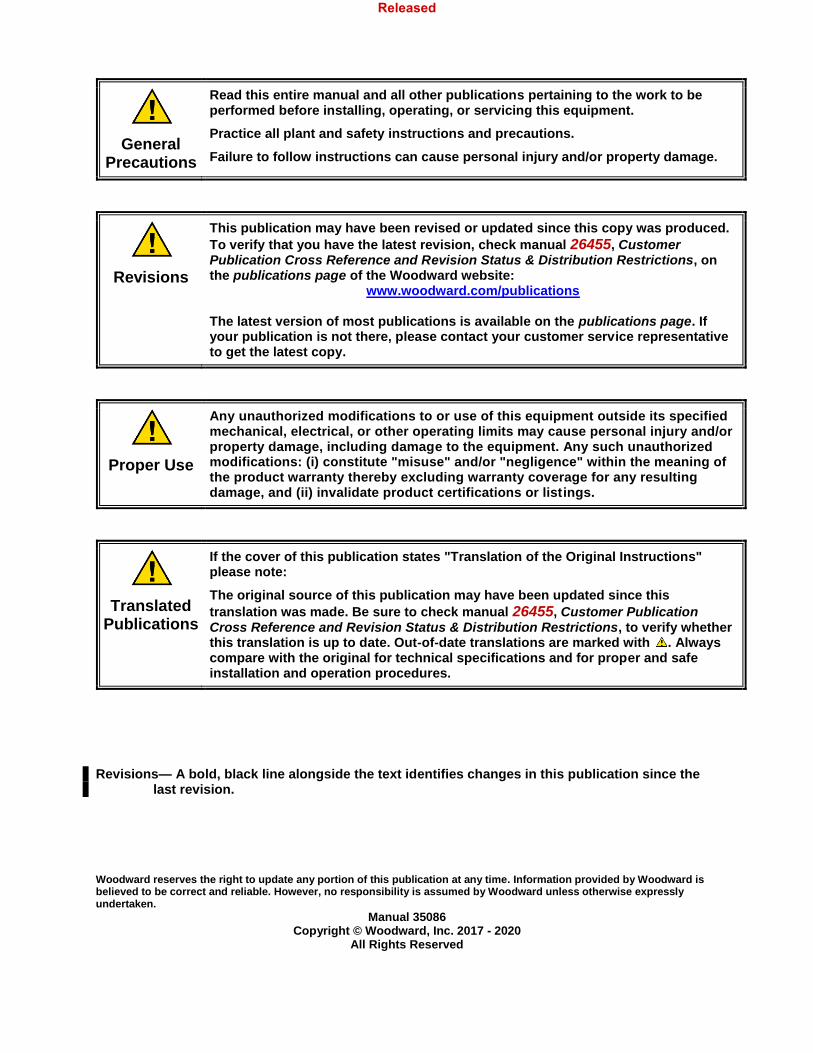
General Precautions
Read this entire manual and all other publications pertaining to the work to be performed before installing, operating, or servicing this equipment.
Practice all plant and safety instructions and precautions.
Failure to follow instructions can cause personal injury and/or property damage.
Revisions
This publication may have been revised or updated since this copy was produced.
To verify that you have the latest revision, check manual 26455, Customer Publication Cross Reference and Revision Status & Distribution Restrictions, on the publications page of the Woodward website:
www.woodward.com/publications The latest version of most publications is available on the publications page. If your publication is not there, please contact your customer service representative to get the latest copy.
Proper Use
Any unauthorized modifications to or use of this equipment outside its specified mechanical, electrical, or other operating limits may cause personal injury and/or property damage, including damage to the equipment. Any such unauthorized modifications: (i) constitute "misuse" and/or "negligence" within the meaning of the product warranty thereby excluding warranty coverage for any resulting damage, and (ii) invalidate product certifications or listings.
Translated Publications
If the cover of this publication states "Translation of the Original Instructions" please note:
The original source of this publication may have been updated since this
translation was made. Be sure to check manual 26455, Customer Publication Cross Reference and Revision Status & Distribution Restrictions, to verify whether this translation is up to date. Out-of-date translations are marked with . Always compare with the original for technical specifications and for proper and safe installation and operation procedures.
Revisions— A bold, black line alongside the text identifies changes in this publication since the
last revision. Woodward reserves the right to update any portion of this publication at any time. Information provided by Woodward is believed to be correct and reliable. However, no responsibility is assumed by Woodward unless otherwise expressly undertaken.
Manual 35086 Copyright © Woodward, Inc. 2017 - 2020
All Rights Reserved
Released
Manual 35086 ProTech-GII with Math Functions
Woodward 1
Contents
WARNINGS AND NOTICES .............................................................................................................. 8
ELECTROSTATIC DISCHARGE AWARENESS .................................................................................... 9
REGULATORY COMPLIANCE ........................................................................................................ 10
ACRONYMS AND DEFINITIONS ...................................................................................................... 13
CHAPTER 1. GENERAL INFORMATION ........................................................................................... 14 Purpose and Scope ..................................................................................................................................... 14 How to Use This Manual ............................................................................................................................. 14 Description .................................................................................................................................................. 14 Applications ................................................................................................................................................. 15 What’s New ................................................................................................................................................. 17
CHAPTER 2. INSTALLATION ......................................................................................................... 19 Introduction.................................................................................................................................................. 19 Unpacking ................................................................................................................................................... 19 Hardware Installation Procedure ................................................................................................................. 19 Enclosures................................................................................................................................................... 20 Module Removal and Installation—Bulkhead Mount Package ................................................................... 23 Module Removal and Installation—Panel Mount Package ......................................................................... 31 Mounting Location Considerations .............................................................................................................. 32 Power Supply Requirements....................................................................................................................... 33 Input/Output Specifications ......................................................................................................................... 35 Shielded Wiring ........................................................................................................................................... 38 Control Wiring Guidelines ........................................................................................................................... 38
CHAPTER 3. FUNCTIONALITY ....................................................................................................... 50 Introduction.................................................................................................................................................. 50 Features ...................................................................................................................................................... 50 Product Models ........................................................................................................................................... 53 Inputs and Outputs ...................................................................................................................................... 59 Overspeed and Over-Acceleration Detection Logic .................................................................................... 61 Speed Diagnostics ...................................................................................................................................... 64 Start Logic ................................................................................................................................................... 64 Test Routines .............................................................................................................................................. 66 Alarm and Trip Latches ............................................................................................................................... 68 System Logs ............................................................................................................................................... 70 ProTech-GII Response Time Performance ................................................................................................. 71
CHAPTER 4. FRONT PANEL INTERFACE ........................................................................................ 74 Introduction.................................................................................................................................................. 74 Screen Layout ............................................................................................................................................. 75 Keypad Functions ....................................................................................................................................... 76 Navigation ................................................................................................................................................... 77 Passwords ................................................................................................................................................... 78 Monitor Menu .............................................................................................................................................. 79 View Logs .................................................................................................................................................... 91
CHAPTER 5. CONFIGURATION USING THE FRONT PANEL ............................................................... 94 Introduction.................................................................................................................................................. 94 Editing Configuration Settings from the Front Panel ................................................................................... 95 Configure Menu Page ................................................................................................................................. 95 Configuration Procedure ............................................................................................................................. 96
CHAPTER 6. TEST ROUTINES ..................................................................................................... 113 Test Modes Menu ..................................................................................................................................... 113
Released
Manual 35086 ProTech-GII with Math Functions
Woodward 2
Temporary Overspeed Setpoint Test ........................................................................................................ 113 Manual Simulated Speed Test .................................................................................................................. 116 Auto Simulated Speed Test ...................................................................................................................... 118 Auto-Sequence Test ................................................................................................................................. 120 Lamp Test ................................................................................................................................................. 122 General Testing Notes .............................................................................................................................. 122
CHAPTER 7. PROGRAMMING AND CONFIGURATION TOOL (PCT) ................................................. 123 General ...................................................................................................................................................... 123 Installation of the PCT ............................................................................................................................... 123 PCT Levels of Operation ........................................................................................................................... 124 Using the PCT ........................................................................................................................................... 125
CHAPTER 8. CONFIGURATION USING THE PCT ........................................................................... 142 Introduction................................................................................................................................................ 142 Configuration Settings ............................................................................................................................... 143 Input Configuration .................................................................................................................................... 145 Functions Configuration ............................................................................................................................ 150 Configuration Checks ................................................................................................................................ 154 Error Messages ......................................................................................................................................... 155
CHAPTER 9. MODBUS COMMUNICATIONS ................................................................................... 156 Introduction................................................................................................................................................ 156 Monitor Only .............................................................................................................................................. 156 Monitor and Control ................................................................................................................................... 156 Modbus Interface ...................................................................................................................................... 157 Port Adjustments ....................................................................................................................................... 157 ProTech-GII Parameter Addresses ........................................................................................................... 157
CHAPTER 10. SAFETY MANAGEMENT ........................................................................................ 163 Product Variations Certified ...................................................................................................................... 163 Safe State.................................................................................................................................................. 163 SIL Specifications ...................................................................................................................................... 163 Failure Rate Data ...................................................................................................................................... 164 Response Time Data ................................................................................................................................ 164 Limitations ................................................................................................................................................. 164 Management of Functional Safety ............................................................................................................ 164 Restrictions................................................................................................................................................ 165 Competence of Personnel......................................................................................................................... 165 Operation and Maintenance Practice ........................................................................................................ 165 Installation and Site Acceptance Testing .................................................................................................. 165 Functional Testing after Initial Installation ................................................................................................. 165 Functional Testing after Changes ............................................................................................................. 165 Proof Testing (Functional Test) ................................................................................................................. 165
CHAPTER 11 TROUBLESHOOTING .............................................................................................. 167 Introduction................................................................................................................................................ 167
CHAPTER 12. PRODUCT SUPPORT AND SERVICE OPTIONS ......................................................... 174 Product Support Options ........................................................................................................................... 174 Product Service Options ........................................................................................................................... 174 Returning Equipment for Repair ............................................................................................................... 175 Replacement Parts .................................................................................................................................... 176 Engineering Services ................................................................................................................................ 176 Contacting Woodward’s Support Organization ......................................................................................... 176 Technical Assistance ................................................................................................................................ 177
CHAPTER 13. ASSET MANAGEMENT .......................................................................................... 178 Product Storage Recommendations ......................................................................................................... 178 Refurbishment Period Recommendation .................................................................................................. 178
APPENDIX A. MODBUS ETHERNET GATEWAY INFORMATION ........................................................ 179
Released
Manual 35086 ProTech-GII with Math Functions
Woodward 3
Introduction................................................................................................................................................ 179 B&B Electronics Setup .............................................................................................................................. 179 Lantronix Setup ......................................................................................................................................... 183
APPENDIX B. PROTECH-GII CONFIGURATION WORKSHEET......................................................... 188
REVISION HISTORY ................................................................................................................... 191
DECLARATIONS ........................................................................................................................ 192
The following are trademarks of Woodward, Inc.: ProTech Woodward The following are trademarks of their respective companies: Modbus (Schneider Automation Inc.) Pentium (Intel Corporation)
Illustrations and Tables Figure 1-1. Typical ProTech-GII Application (Voted Trip Relay Models) .................................................... 16 Figure 1-2. Typical ProTech-GII Application (Independent Trip Relay Models) ......................................... 16 Figure 1-3. Typical Gas Turbine Application (Voted Trip Relay Models) .................................................... 17 Figure 2-1. Typical ProTech-GII Bulkhead Package—Front View.............................................................. 20 Figure 2-2a. Typical ProTech-GII Bulkhead Package—Front Door Open .................................................. 21 Figure 2-2b. Bulkhead Schematic Showing Front Panel A Connection to Module A and Front Panel C
Connection to Module C—Top View ...................................................................................... 21 Figure 2-3. Mounting Outline Diagram for Bulkhead-Mounted Models ...................................................... 22 Figure 2-4a. Typical ProTech-GII Panel Mount Package—Front View ...................................................... 26 Figure 2-4b. Typical ProTech-GII Panel Mount Package—Rear View with Cover ..................................... 26 Figure 2-4c. Typical ProTech-GII Panel Mount Package—Rear View without Cover Showing Module
Orientation .............................................................................................................................. 27 Figure 2-4d. Panel Mount Schematic Showing Front Panel A Connection to Module A and Front Panel C
Connection to Module C—Top View ...................................................................................... 27 Figure 2-5a. Mounting Outline Diagram for Panel-Mount Models .............................................................. 28 Figure 2-5b. Mounting Outline Diagram for Panel-Mount Models .............................................................. 29 Figure 2-5c. Panel Cutout Diagram for Panel-Mount Models ..................................................................... 30 Figure 2-6. Screw Connection Terminal Block............................................................................................ 39 Figure 2-7. Inside View of ProTech-GII ....................................................................................................... 40 Figure 2-8. ProTech-GII Control Wiring Diagram........................................................................................ 41 Figure 2-9. Trip Module—Included within Voted Trip Relay Units Only ..................................................... 42 Figure 2-10a. Power Supply Field Wiring Routing & Stress Relief Diagram .............................................. 42 Figure 2-10b. I/O Wiring Routing & Stress Relief Diagram ......................................................................... 43 Figure 2-10c. Relay Output Field Wiring Routing & Stress Relief Diagram ................................................ 43 Figure 2-11a. Example MPU (Passive Magnetic Pickup Unit) Wiring ........................................................ 44 Figure 2-11b. Example Proximity Probe (Active Magnetic Pickup Unit) Wiring (Internal Power) ............... 45 Figure 2-11c. Example Proximity Probe (Active Magnetic Pickup Unit) Wiring (External Power, Non-
preferred) ................................................................................................................................ 45 Figure 2-11d. Example Eddy Current Probe (Active Magnetic Pickup Unit) Wiring ................................... 45 Figure 2-12a. Example Standard Discrete Input Wiring (Internal Power Option) ....................................... 46 Figure 2-12b. Example Standard Discrete Input Wiring (External Power Option) ...................................... 46 Figure 2-13. Example Analog Output Wiring .............................................................................................. 47 Figure 2-14a. Example Trip Relay Output Wiring ....................................................................................... 47 Figure 2-14b. Example Trip Relay Wiring (per Module) (Independent Trip Relay) (Internal Supply) ......... 48 Figure 2-14c. Example Trip Relay Wiring (per Module) (Independent Trip Relay) (External Supply) ........ 48 Figure 2-14d. Example Trip Relay Wiring (Voted Trip Relay Models) ........................................................ 49
Released
Manual 35086 ProTech-GII with Math Functions
Woodward 4
Figure 2-14e. Example Alarm Relay Wiring (Internal Supply) .................................................................... 49 Figure 3-1. Module Diagram without Speed Redundancy Manager Configured ........................................ 51 Figure 3-2. Module Diagram with Speed Redundancy Manager Configured ............................................. 52 Figure 3-3. Basic Functional Overview of Independent Trip Relay Models ................................................ 53 Figure 3-4. Functional Diagram of Single ProTech-GII module with Independent Trip Relay Outputs ...... 54 Figure 3-5. Example TMR Trip Block Assembly Interface .......................................................................... 55 Figure 3-6. Basic Functional Overview of Voted Trip Relay Models........................................................... 56 Figure 3-7. Functional Diagram of Single ProTech-GII Module with Voted Trip Relay Outputs ................. 57 Figure 3-8. Simplex Trip Block Assembly ................................................................................................... 58 Figure 3-9. Dual Redundant Trip Block Assembly ...................................................................................... 59 Figure 3-10. Over-Acceleration Enabling Diagram ..................................................................................... 62 Figure 3-11. Start Logic Diagram ................................................................................................................ 65 Figure 3-12. Speed Fail Trip Diagram ......................................................................................................... 65 Figure 3-13. Speed Fail Timeout Trip Diagram ........................................................................................... 66 Figure 3-14. Total System Response Time Based on Sensed Frequency Level for Independent Trip Relay
Models when Speed Redundancy Manager Function is not Configured ............................... 71 Figure 3-15. Total System Response Time Based on Sensed Frequency Level for Independent Trip Relay
Models when Speed Redundancy Manager Function is Configured ..................................... 72 Figure 3-16. Total System Response Time Based on Sensed Frequency Level for 2oo3 Voted Trip Relay
Models when Speed Redundancy Manager Function is not Configured ............................... 72 Figure 3-17. Total System Response Time Based on Sensed Frequency Level for 2oo3 Voted Trip Relay
Models when Speed Redundancy Manager Function is Configured ..................................... 73 Figure 3-18. Response Time Definition ...................................................................................................... 73 Figure 4-1. ProTech-GII Front Panel .......................................................................................................... 74 Figure 4-2. ProTech-GII Screen .................................................................................................................. 75 Figure 4-3. ProTech-GII Faceplate ............................................................................................................. 76 Figure 4-4. Home screen (with Alarm) ........................................................................................................ 77 Figure 4-5. Home screen (with Trip) ........................................................................................................... 77 Figure 4-6. Password Entry Screen Example ............................................................................................. 78 Figure 4-7. Monitor Menu ............................................................................................................................ 79 Figure 4-8. Monitor Summary Screen Example .......................................................................................... 80 Figure 4-9. Monitor Trip Latch Screen Example ......................................................................................... 80 Figure 4-10. Monitor Alarm Latch Screen Example .................................................................................... 81 Figure 4-11. Monitor Dedicated Discrete Inputs Screen Example .............................................................. 82 Figure 4-12. Monitor Speed Input Screen Example .................................................................................... 83 Figure 4-13. Monitor Speed Redundancy Manager Screen Example ........................................................ 83 Figure 4-14. Monitor Acceleration Redundancy Manager Screen Example ............................................... 84 Figure 4-15. Monitor Speed Fail Timer Screen Example ............................................................................ 85 Figure 4-16. Monitor Speed Readout (Home) Screen Example ................................................................. 85 Figure 4-17. Monitor Shared Start Input Screen Example .......................................................................... 86 Figure 4-18. Monitor Shared Reset Input Screen Example ........................................................................ 86 Figure 4-19. Monitor Shared Speed Fail Override Input Screen Example ................................................. 87 Figure 4-20. Monitor Modbus Screen Example .......................................................................................... 87 Figure 4-21. Monitor/Set Date & Time Screen Example ............................................................................. 88 Figure 4-22. Edit/Change Mode Active Screen Example ........................................................................... 88 Figure 4-23. Highlight Time Field to Edit Screen Example ......................................................................... 89 Figure 4-24. Ready to Apply Changes Screen Example ............................................................................ 89 Figure 4-25. Monitor System Status ........................................................................................................... 90 Figure 4-26. Monitor Module Information .................................................................................................... 90 Figure 4-27. Logs Menu Screen Example .................................................................................................. 91 Figure 4-28. Overspeed/Over-Acceleration Log Screen Example.............................................................. 91 Figure 4-29. Trip Log Screen Example ....................................................................................................... 92 Figure 4-30. Alarm Log Screen Example .................................................................................................... 92 Figure 4-31. Peak Speed/Acceleration Log Screen Example ..................................................................... 93 Figure 4-32. Reset Logs Screen Example .................................................................................................. 93 Figure 5-2. Configure Menu Screen Example............................................................................................. 95 Figure 5-3. Save Configuration Screen Example ....................................................................................... 97 Figure 5-4. Configure Display Screen Example .......................................................................................... 97 Figure 5-5. Configure Speed Submenu Screen Example ........................................................................... 98
Released
Manual 35086 ProTech-GII with Math Functions
Woodward 5
Figure 5-6. Configure Speed Input Screen Example .................................................................................. 99 Figure 5-7. Configure Acceleration Screen Example ................................................................................ 100 Figure 5-8. Configure Start Logic .............................................................................................................. 100 Figure 5-9. Configure Speed Redundancy Manager Screen Example .................................................... 101 Figure 5-10. Configure Acceleration Redundancy Manager Screen Example ......................................... 102 Figure 5-11. Configure Trip Latch Screen Example ................................................................................. 102 Figure 5-12. Configure Alarm Latch Screen Example .............................................................................. 103 Figure 5-13. Configure Dedicated Discrete Submenu Screen Example .................................................. 103 Figure 5-14. Configure Start Input Sharing Screen Example ................................................................... 104 Figure 5-15. Configure Reset Input Sharing Screen Example .................................................................. 104 Figure 5-16. Configure Speed Fail Override Input Sharing Screen Example ........................................... 105 Figure 5-17. Configure Test Modes Screen Example ............................................................................... 105 Figure 5-18. Configure Auto-Sequence Test Screen Example................................................................. 106 Figure 5-19. Configure Modbus Screen Example ..................................................................................... 107 Figure 5-20. Configure Power Supply Alarms Screen Example ............................................................... 107 Figure 5-21. Configuration Management Menu Screen Example ............................................................. 108 Figure 5-22. Configuration Overview Screen Example ............................................................................. 108 Figure 5-23. Configuration Compare Screen Example ............................................................................. 109 Figure 5-24. Configuration Copy Screen Example ................................................................................... 110 Figure 5-25. Configuration Copy Screen Example ................................................................................... 111 Figure 5-26. Password Change Screen Example ..................................................................................... 111 Figure 6-1. Test Modes Menu ................................................................................................................... 113 Figure 6-2a. Temporary Overspeed Test Screen Example ...................................................................... 113 Figure 6-2b. Temporary Overspeed Test Screen Examples .................................................................... 115 Figure 6-3. Manual Simulated Speed Test Screen Example .................................................................... 116 Figure 6-4. Test Frequency Resolution ..................................................................................................... 117 Figure 6-5. Manual Simulated Speed Test Screen Example .................................................................... 117 Figure 6-6. Auto Simulated Speed Test Screen Example ........................................................................ 118 Figure 6-7. Auto Sequence Test (Periodic Test Timer Enabled) Screen Example .................................. 120 Figure 6-8. Lamp Test ............................................................................................................................... 122 Figure 7-1 Website Search Results .......................................................................................................... 123 Figure 7-2. Host Computer Control Panel Display Settings ...................................................................... 124 Figure 7-4. ProTech-GII PCT Off-Line Window ........................................................................................ 125 Figure 7-5. Button Status (Connected) ..................................................................................................... 126 Figure 7-6. Button Status ( Not Connected).............................................................................................. 126 Figure 7-7. Information Status Bar (Not Connected) ................................................................................ 126 Figure 7-8. Information Status Bar Example (Connected) ........................................................................ 126 Figure 7-9. ProTech-GII PCT Off-Line Window ........................................................................................ 127 Figure 7-10. Status Bar and Button Status before Connection ................................................................. 127 Figure 7-11. PCT Connect Options Window ............................................................................................. 128 Figure 7-12. Status Bar and Button Status after Connection .................................................................... 128 Figure 7-13. PCT Security Log-In Window ............................................................................................... 128 Figure 7-14. Drop-Down Menu “Settings” ................................................................................................. 129 Figure 7-15. Prompt to Set Settings File Default Values ......................................................................... 130 Figure 7-16. Prompt for Settings File to Modify ........................................................................................ 130 Figure 7-17. Prompt to Connect ................................................................................................................ 131 Figure 7-18. Prompt for Settings File to Edit ............................................................................................. 131 Figure 7-19. Prompt for Settings File to Load ........................................................................................... 132 Figure 7-20. Configuration Error ............................................................................................................... 133 Figure 7-21. Compare Settings File Differences ....................................................................................... 133 Figure 7-22. Settings File Differences ....................................................................................................... 133 Figure 7-23. PCT On-Line Window ........................................................................................................... 134 Figure 7-24. Edit/View Configuration On-Line Window Example ............................................................. 135 Figure 7-25 Valid Range Display for Sudden Speed Loss Threshold Setting .......................................... 136 Figure 7-26 Options Displayed When No Changes are Detected ............................................................ 136 Figure 7-27 Options Displayed When Changes are Detected .................................................................. 136 Figure 7-28 Incorrect Log-In Level ............................................................................................................ 137 Figure 7-29 Configuration Error ................................................................................................................ 137 Figure 7-30 Module is not Tripped ............................................................................................................ 137
Released
Manual 35086 ProTech-GII with Math Functions
Woodward 6
Figure 7-31. Configuration Error Log Example ......................................................................................... 138 Figure 7-32. Trip and Alarm Log Example ................................................................................................ 139 Figure 7-33. Overspeed/Acceleration Log Example ................................................................................. 140 Figure 7-34. Module Faults Log Example ................................................................................................. 141 Figure 8-1. ProTech-GII PCT “Edit/View Configuration” Screen (Connected) ......................................... 143 Figure 8-2. Speed and Acceleration Configuration Example .................................................................... 145 Figure 8-3. Input Sharing Selection Configuration Example ..................................................................... 148 Figure 8-4. Modbus Configuration Example ............................................................................................. 149 Figure 8-5. Test Modes Configuration Example ....................................................................................... 150 Figure 8-6. Start Logic & Power Supply Alarms Configuration Example .................................................. 152 Figure 8-7. Other Outputs Configuration Example ................................................................................... 153 Figure 8-8. Configuration Error window .................................................................................................... 155 Figure 8-9. Data Entry Range Error Example ........................................................................................... 155 Figure A-1. Wiring ..................................................................................................................................... 180 Figure A-2. RS-485 2-wire ........................................................................................................................ 180 Figure A-3. Network Settings .................................................................................................................... 181 Figure A-4. Modbus TCP Settings ............................................................................................................ 181 Figure A-5. Serial Communication Settings .............................................................................................. 182 Figure A-6. Serial Modbus Settings .......................................................................................................... 182 Figure A-7. RS-232 Wiring ........................................................................................................................ 183 Figure A-8. RS-285 2-wire Wiring ............................................................................................................. 184 Figure A-9. Overview ................................................................................................................................ 185 Figure A-10. Network Menu ...................................................................................................................... 185 Figure A-11. Serial Settings Menu ............................................................................................................ 186 Figure A-12. Modem Control Menu ........................................................................................................... 186 Figure A-13. Advanced Menu ................................................................................................................... 187 Table 1-1. Available ProTech-GII Models ................................................................................................... 15 Table 1-2 ProTech GII conversion compatibility ......................................................................................... 18 Table 2-1. Environmental Specifications ..................................................................................................... 33 Table 2-2a. Low Voltage Input Specifications ............................................................................................. 33 Table 2-2b. High Voltage Input Specifications ............................................................................................ 33 Table 2-2c. Power Supply Input Specifications .......................................................................................... 34 Table 2-3 Relay Output Power Supply Specifications ................................................................................ 34 Table 2-4. General I/O Specifications ......................................................................................................... 35 Table 2-5a. Passive Probe Specifications .................................................................................................. 35 Table 2-5b. Active Probe Specifications ..................................................................................................... 35 Table 2-6a. Independent Trip Relay Specifications .................................................................................... 36 Table 2-6b. Voted Trip Relay Specifications ............................................................................................... 36 Table 2-7. Alarm Relay Specifications ........................................................................................................ 36 Table 2-8. Dedicated Discrete Input Specifications .................................................................................... 37 Table 2-9. Analog Output Specifications ..................................................................................................... 37 Table 2-10. Serial Port (RS-232/RS-485) Specifications ............................................................................ 37 Table 4-1. Keypad Keys Function Definitions ............................................................................................. 76 Table 5-1. Front Panel Functions that Can Be Modified ............................................................................. 94 Table 5-2. Home Screen Valid Values ........................................................................................................ 98 Table 6-1. Simulated Speed Resolution ................................................................................................... 116 Table 7-3. Service Port and Serial Cable Specifications .......................................................................... 124 Table 8-1. Home Screen Valid Values ...................................................................................................... 144 Table 8-2. Configuration Check Definitions .............................................................................................. 154 Table 9-1. Modbus Communication Port Specifications ........................................................................... 156 Table 9-2. Supported Modbus Function Codes ........................................................................................ 157 Table 9-3. Modbus Serial Communication Port Settings .......................................................................... 157 Table 9-4. Boolean Write Addresses (Code 05) ....................................................................................... 159 Table 9-5. Boolean Read Addresses (Code 02) ....................................................................................... 159 Table 9-6. Analog Read Addresses (Code 04) ......................................................................................... 162 Table 10-1. Trip Relay Safe State Configuration ...................................................................................... 163 Table 10-2. SIL Specifications .................................................................................................................. 163
Released

Manual 35086 ProTech-GII with Math Functions
Woodward 7
Table 10-3. ProTech-GII SIL3 Numbers: .................................................................................................. 164 Table 10-4. Failure Rate ........................................................................................................................... 164 Table 11-1. I/O Troubleshooting ............................................................................................................... 167 Table 11-2. Trip Indications....................................................................................................................... 170 Table 11-3. Alarm Indications ................................................................................................................... 172
Released

Manual 35086 ProTech-GII with Math Functions
Woodward 8
Warnings and Notices
Important Definitions This is the safety alert symbol used to alert you to potential personal injury hazards. Obey all safety messages that follow this symbol to avoid possible injury or death.
DANGER - Indicates a hazardous situation, which if not avoided, will result in death or serious injury.
WARNING - Indicates a hazardous situation, which if not avoided, could result in death or serious injury.
CAUTION - Indicates a hazardous situation, which if not avoided, could result in minor or moderate injury.
NOTICE - Indicates a hazard that could result in property damage only (including damage to the control).
IMPORTANT - Designates an operating tip or maintenance suggestion.
Overspeed / Overtemperature /
Overpressure
The engine, turbine, or other type of prime mover should be equipped with an overspeed shutdown device to protect against runaway or damage to the prime mover with possible personal injury, loss of life, or property damage.
The overspeed shutdown device must be totally independent of the prime mover control system. An overtemperature or overpressure shutdown device may also be needed for safety, as appropriate.
Personal Protective Equipment
The products described in this publication may present risks that could lead to personal injury, loss of life, or property damage. Always wear the appropriate personal protective equipment (PPE) for the job at hand. Equipment that should be considered includes but is not limited to:
Eye Protection
Hearing Protection
Hard Hat
Gloves
Safety Boots
Respirator
Always read the proper Material Safety Data Sheet (MSDS) for any working fluid(s) and comply with recommended safety equipment.
Start-up
Be prepared to make an emergency shutdown when starting the engine, turbine, or other type of prime mover, to protect against runaway or overspeed with possible personal injury, loss of life, or property damage.
Released

Manual 35086 ProTech-GII with Math Functions
Woodward 9
Electrostatic Discharge Awareness
Electrostatic Precautions
Electronic controls contain static-sensitive parts. Observe the following precautions to prevent damage to these parts:
Discharge body static before handling the control (with power to the control turned off, contact a grounded surface and maintain contact while handling the control).
Avoid all plastic, vinyl, and Styrofoam (except antistatic versions) around printed circuit boards.
Do not touch the components or conductors on a printed circuit board with your hands or with conductive devices.
To prevent damage to electronic components caused by improper handling, read and observe the precautions in Woodward manual
82715, Guide for Handling and Protection of Electronic Controls, Printed Circuit Boards, and Modules.
Follow these precautions when working with or near the control. 1. Avoid the build-up of static electricity on your body by not wearing clothing made of synthetic
materials. Wear cotton or cotton-blend materials as much as possible because these do not store static electric charges as much as synthetics.
2. Do not remove the printed circuit board (PCB) from the control cabinet unless absolutely necessary. If you must remove the PCB from the control cabinet, follow these precautions:
Do not touch any part of the PCB except the edges.
Do not touch the electrical conductors, the connectors, or the components with conductive devices or with your hands.
When replacing a PCB, keep the new PCB in the plastic antistatic protective bag it comes in until you are ready to install it. Immediately after removing the old PCB from the control cabinet, place it in the antistatic protective bag.
Released
Manual 35086 ProTech-GII with Math Functions
Woodward 10
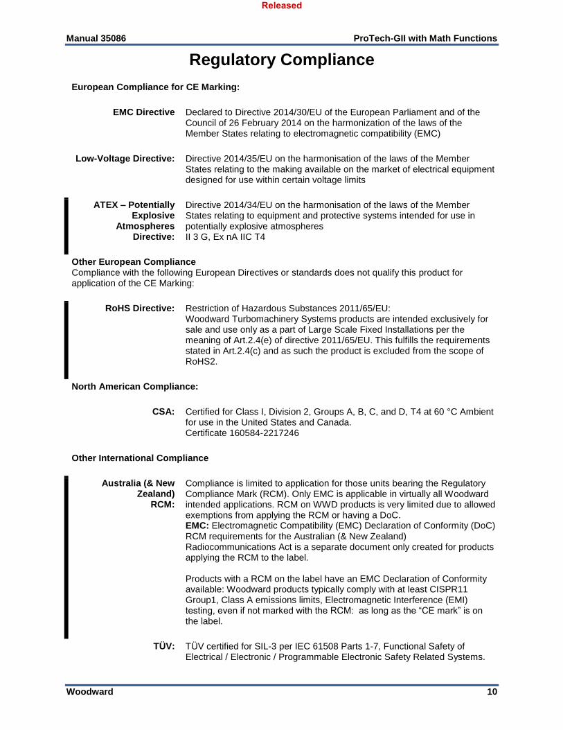
Regulatory Compliance
European Compliance for CE Marking:
EMC Directive Declared to Directive 2014/30/EU of the European Parliament and of the Council of 26 February 2014 on the harmonization of the laws of the Member States relating to electromagnetic compatibility (EMC)
Low-Voltage Directive: Directive 2014/35/EU on the harmonisation of the laws of the Member States relating to the making available on the market of electrical equipment designed for use within certain voltage limits
ATEX – Potentially Explosive
Atmospheres Directive:
Directive 2014/34/EU on the harmonisation of the laws of the Member States relating to equipment and protective systems intended for use in potentially explosive atmospheres II 3 G, Ex nA IIC T4
Other European Compliance Compliance with the following European Directives or standards does not qualify this product for application of the CE Marking:
RoHS Directive: Restriction of Hazardous Substances 2011/65/EU: Woodward Turbomachinery Systems products are intended exclusively for sale and use only as a part of Large Scale Fixed Installations per the meaning of Art.2.4(e) of directive 2011/65/EU. This fulfills the requirements stated in Art.2.4(c) and as such the product is excluded from the scope of RoHS2.
North American Compliance:
CSA: Certified for Class I, Division 2, Groups A, B, C, and D, T4 at 60 °C Ambient for use in the United States and Canada. Certificate 160584-2217246
Other International Compliance
Australia (& New Zealand)
RCM:
Compliance is limited to application for those units bearing the Regulatory Compliance Mark (RCM). Only EMC is applicable in virtually all Woodward intended applications. RCM on WWD products is very limited due to allowed exemptions from applying the RCM or having a DoC. EMC: Electromagnetic Compatibility (EMC) Declaration of Conformity (DoC) RCM requirements for the Australian (& New Zealand) Radiocommunications Act is a separate document only created for products applying the RCM to the label. Products with a RCM on the label have an EMC Declaration of Conformity available: Woodward products typically comply with at least CISPR11 Group1, Class A emissions limits, Electromagnetic Interference (EMI) testing, even if not marked with the RCM: as long as the “CE mark” is on the label.
TÜV: TÜV certified for SIL-3 per IEC 61508 Parts 1-7, Functional Safety of Electrical / Electronic / Programmable Electronic Safety Related Systems.
Released
Manual 35086 ProTech-GII with Math Functions
Woodward 11
Other Compliance
Gas Corrosion: IEC60068-2-60:1995 Part 2.60 Methods 1 and 4 (conformal coating)
Machinery Protection: API670, API612, & API-611 compliant
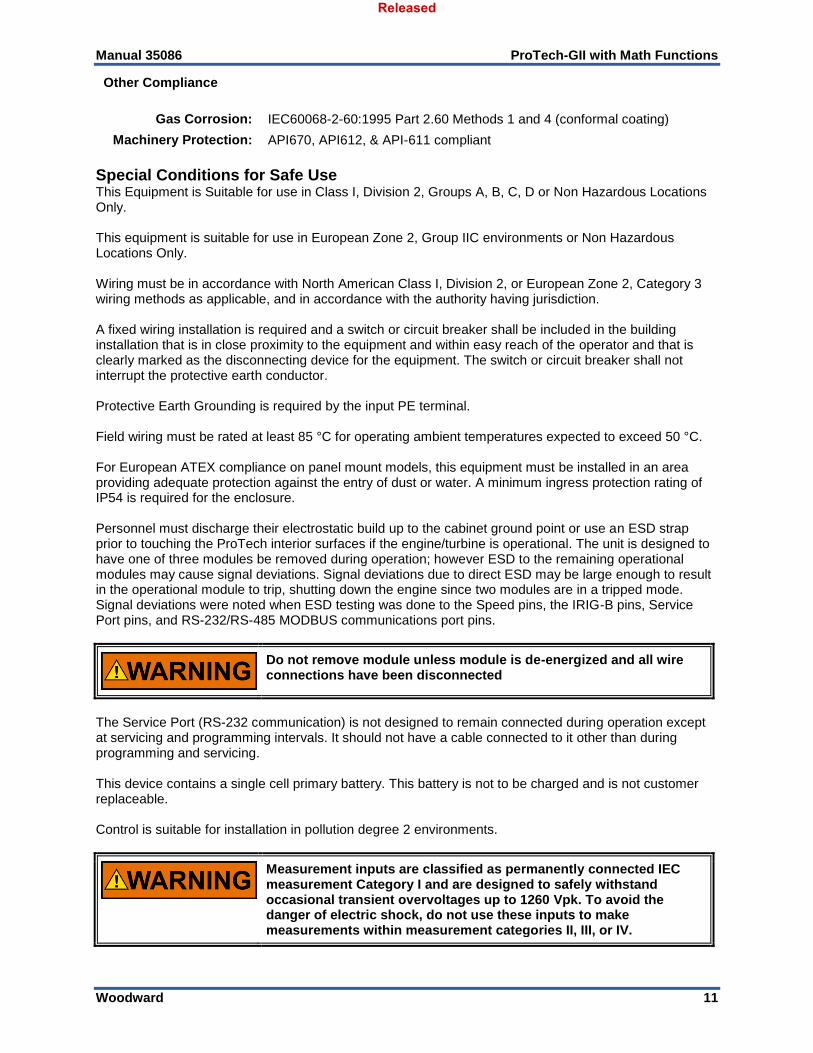
Special Conditions for Safe Use This Equipment is Suitable for use in Class I, Division 2, Groups A, B, C, D or Non Hazardous Locations Only. This equipment is suitable for use in European Zone 2, Group IIC environments or Non Hazardous Locations Only. Wiring must be in accordance with North American Class I, Division 2, or European Zone 2, Category 3 wiring methods as applicable, and in accordance with the authority having jurisdiction. A fixed wiring installation is required and a switch or circuit breaker shall be included in the building installation that is in close proximity to the equipment and within easy reach of the operator and that is clearly marked as the disconnecting device for the equipment. The switch or circuit breaker shall not interrupt the protective earth conductor. Protective Earth Grounding is required by the input PE terminal. Field wiring must be rated at least 85 °C for operating ambient temperatures expected to exceed 50 °C. For European ATEX compliance on panel mount models, this equipment must be installed in an area providing adequate protection against the entry of dust or water. A minimum ingress protection rating of IP54 is required for the enclosure. Personnel must discharge their electrostatic build up to the cabinet ground point or use an ESD strap prior to touching the ProTech interior surfaces if the engine/turbine is operational. The unit is designed to have one of three modules be removed during operation; however ESD to the remaining operational modules may cause signal deviations. Signal deviations due to direct ESD may be large enough to result in the operational module to trip, shutting down the engine since two modules are in a tripped mode. Signal deviations were noted when ESD testing was done to the Speed pins, the IRIG-B pins, Service Port pins, and RS-232/RS-485 MODBUS communications port pins.
Do not remove module unless module is de-energized and all wire connections have been disconnected
The Service Port (RS-232 communication) is not designed to remain connected during operation except at servicing and programming intervals. It should not have a cable connected to it other than during programming and servicing. This device contains a single cell primary battery. This battery is not to be charged and is not customer replaceable. Control is suitable for installation in pollution degree 2 environments.
Measurement inputs are classified as permanently connected IEC measurement Category I and are designed to safely withstand occasional transient overvoltages up to 1260 Vpk. To avoid the danger of electric shock, do not use these inputs to make measurements within measurement categories II, III, or IV.
Released
Manual 35086 ProTech-GII with Math Functions
Woodward 12
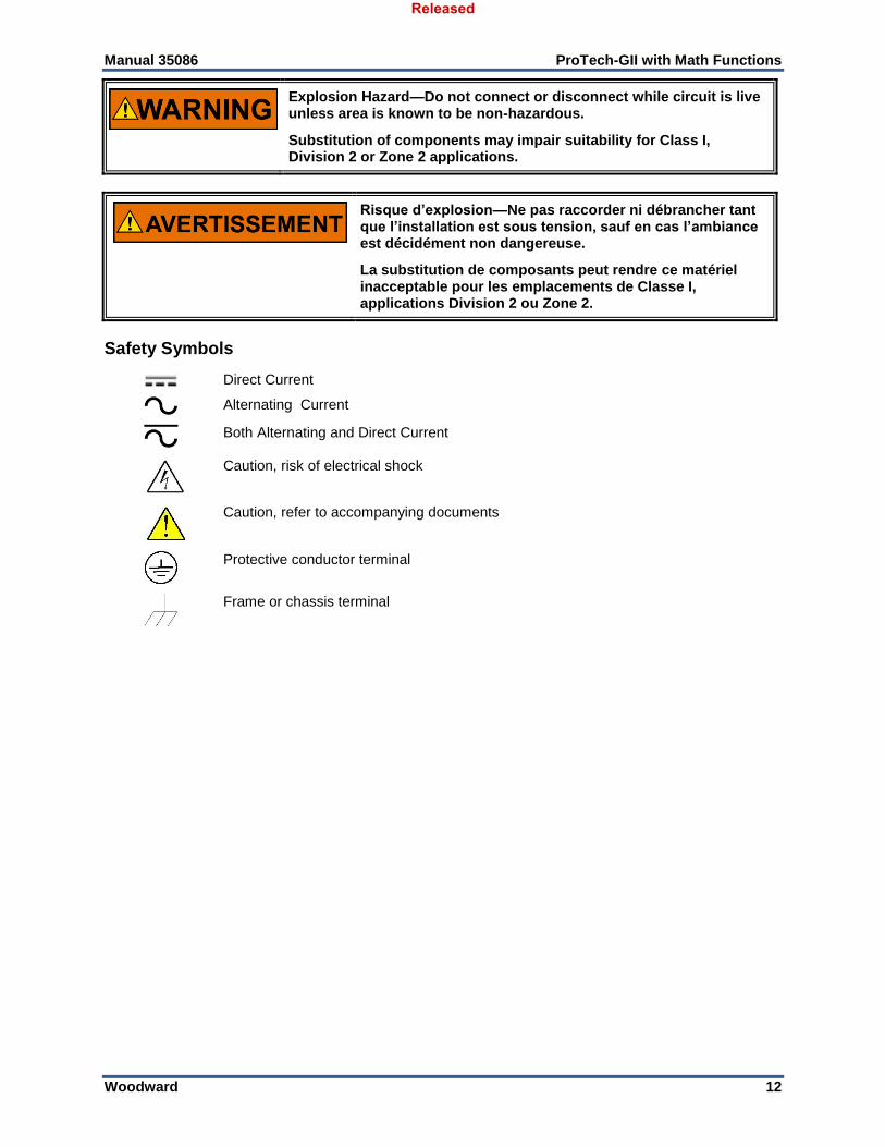
Explosion Hazard—Do not connect or disconnect while circuit is live unless area is known to be non-hazardous.
Substitution of components may impair suitability for Class I, Division 2 or Zone 2 applications.
Risque d’explosion—Ne pas raccorder ni débrancher tant que l’installation est sous tension, sauf en cas l’ambiance est décidément non dangereuse.
La substitution de composants peut rendre ce matériel inacceptable pour les emplacements de Classe I, applications Division 2 ou Zone 2.
Safety Symbols
Direct Current
Alternating Current
Both Alternating and Direct Current
Caution, risk of electrical shock
Caution, refer to accompanying documents
Protective conductor terminal
Frame or chassis terminal
Released
Manual 35086 ProTech-GII with Math Functions
Woodward 13
Acronyms and Definitions
2oo3 2-out-of-3 CAN Controller Area Network CRC Cyclic Redundancy Check
DC Diagnostic Coverage DCS Distributed Control System
mA Milliampere(s) ms Millisecond(s)
HSS High Signal Select LSS Low Signal Select
Module Functionality contained within one of the three identical sections MPU Magnetic Pick-up
PC Personal Computer with Windows operating system (also known as “host computer”) PCT Programming and Configuration Tool PFD Probability of Failure on Demand PFH Probability of dangerous Failure per Hour PLC Programmable Logic Controller
PROX Proximity Probe RPM Revolutions Per Minute RTU Remote Terminal Unit Transmission Protocol
Settings File A file that contains the configuration settings loaded with the ProTech Programming and Configuration Tool (“.wset” is the filename extension)
SFO Speed Fail Override SRM Speed Redundancy Manager
GII ProTech Overspeed Protection Device
Released
Manual 35086 ProTech-GII with Math Functions
Woodward 14
Chapter 1. General Information
Purpose and Scope The purpose of this manual is to provide the necessary background information for applying the ProTech-GII. Topics covered include mechanical installation, electrical wiring, software programming, and troubleshooting. While this manual is primarily targeted at OEM customers, OEMs themselves may find it useful to copy some of the information from this manual into their application user manuals. This manual does not contain instructions for the operation of the complete prime mover system. For prime mover or plant operating instructions, contact the plant-equipment manufacturer. This version of the manual applies to all ProTech-GII models with software 5418-7349. The software version can be identified on the front panel display at power-up or on the “Monitor Module Information” screen, available from the “Monitor Menu”. It can also be found on the “Details...” tab of the Programming and Configuration Tool (PCT). See the “What’s New” section at the end of this chapter for a listing of the changes in this software version.
How to Use This Manual The following summarizes how to install a ProTech-GII into a new or existing system:
Unbox and inspect the hardware.
Install, mount, and wire the hardware following the system installation procedures and
recommendations in Chapter 2.
Configure the device using one of the following options:
o Programming and Configuration Tool (Chapter 7)
o Front Panel (Chapter 5)
Follow the safety and checkout procedures in Chapter 10.
Troubleshooting guidelines are provided in Chapter 11.
Description The ProTech-GII is an overspeed safety device designed to safely shut down steam, gas, and hydro turbines of all sizes upon sensing an overspeed or over-acceleration event. This device accurately monitors turbine rotor speed and acceleration via active or passive MPUs (magnetic pickups) and issues a shutdown command to the turbine’s trip valve(s) or corresponding trip system. The ProTech-GII consists of three independent modules whose trip outputs, dependent upon model used, are either independent or voted in a 2-out-of-3 configuration. An isolated bus architecture is used to share all inputs and latch status information between the three modules. Optionally each ProTech-GII module can be configured to use only its sensed “local” input signals or the voted result of all three modules’ signals in its event latch decision logic. Optionally module trip and alarm latch statuses can also be configured to be shared with all other modules. The ProTech-GII includes Overspeed and Over-acceleration functions as well as time stamped Alarm, and Trip logs. Indication that a test was active at the time of the event is provided on all logs and first-out indications are provided for Trip logs. The ProTech-GII also provides various pre-defined test routines including an automated periodic test routine to assist users with verifying system operation. There are several ways to interface with the ProTech-GII. The front panel allows the user to view current values, and to perform configuration and test functions. All of the features and most of the information
Released
Manual 35086 ProTech-GII with Math Functions
Woodward 15
available from the front panel are also accessible via the Modbus interface. Finally, the Programming and Configuration Tool (PCT) is software that is run on a PC to download log files and manage Settings Files. This product is designed for critical applications and when installed correctly complies with standards API-670, API-612, API-611, and IEC61508 (SIL-3). The following table shows the various hardware configurations (mounting options, power supplies, and trip relay options) available:
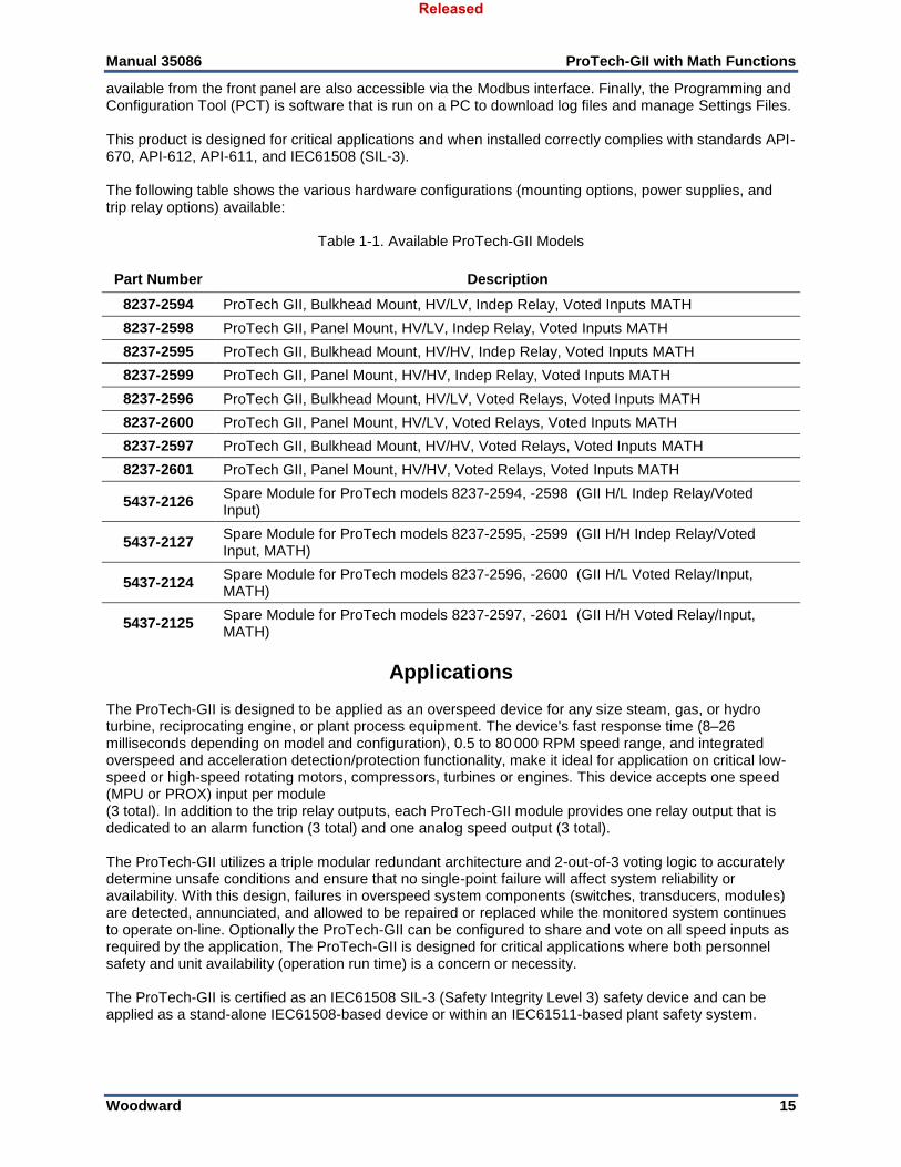
Table 1-1. Available ProTech-GII Models
Part Number Description
8237-2594 ProTech GII, Bulkhead Mount, HV/LV, Indep Relay, Voted Inputs MATH
8237-2598 ProTech GII, Panel Mount, HV/LV, Indep Relay, Voted Inputs MATH
8237-2595 ProTech GII, Bulkhead Mount, HV/HV, Indep Relay, Voted Inputs MATH
8237-2599 ProTech GII, Panel Mount, HV/HV, Indep Relay, Voted Inputs MATH
8237-2596 ProTech GII, Bulkhead Mount, HV/LV, Voted Relays, Voted Inputs MATH
8237-2600 ProTech GII, Panel Mount, HV/LV, Voted Relays, Voted Inputs MATH
8237-2597 ProTech GII, Bulkhead Mount, HV/HV, Voted Relays, Voted Inputs MATH
8237-2601 ProTech GII, Panel Mount, HV/HV, Voted Relays, Voted Inputs MATH
5437-2126 Spare Module for ProTech models 8237-2594, -2598 (GII H/L Indep Relay/Voted Input)
5437-2127 Spare Module for ProTech models 8237-2595, -2599 (GII H/H Indep Relay/Voted Input, MATH)
5437-2124 Spare Module for ProTech models 8237-2596, -2600 (GII H/L Voted Relay/Input, MATH)
5437-2125 Spare Module for ProTech models 8237-2597, -2601 (GII H/H Voted Relay/Input, MATH)
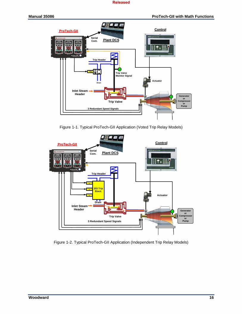
Applications The ProTech-GII is designed to be applied as an overspeed device for any size steam, gas, or hydro turbine, reciprocating engine, or plant process equipment. The device's fast response time (8–26 milliseconds depending on model and configuration), 0.5 to 80 000 RPM speed range, and integrated overspeed and acceleration detection/protection functionality, make it ideal for application on critical low-speed or high-speed rotating motors, compressors, turbines or engines. This device accepts one speed (MPU or PROX) input per module (3 total). In addition to the trip relay outputs, each ProTech-GII module provides one relay output that is dedicated to an alarm function (3 total) and one analog speed output (3 total). The ProTech-GII utilizes a triple modular redundant architecture and 2-out-of-3 voting logic to accurately determine unsafe conditions and ensure that no single-point failure will affect system reliability or availability. With this design, failures in overspeed system components (switches, transducers, modules) are detected, annunciated, and allowed to be repaired or replaced while the monitored system continues to operate on-line. Optionally the ProTech-GII can be configured to share and vote on all speed inputs as required by the application, The ProTech-GII is designed for critical applications where both personnel safety and unit availability (operation run time) is a concern or necessity. The ProTech-GII is certified as an IEC61508 SIL-3 (Safety Integrity Level 3) safety device and can be applied as a stand-alone IEC61508-based device or within an IEC61511-based plant safety system.
Released
Manual 35086 ProTech-GII with Math Functions
Woodward 16
Trip Valve
Inlet SteamHeader
3 Redundant Speed Signals
Control
Actuator
Generatoror
Compressoror
Pump
ProTech-GII
TS
Plant DCS
LS
Trip ValveMonitor Signal
Drain
Trip Header
Serial
Com.
TS
Figure 1-1. Typical ProTech-GII Application (Voted Trip Relay Models)
Trip Valve
Inlet SteamHeader
3 Redundant Speed Signals
Control
Actuator
Generatoror
Compressoror
Pump
ProTech-GII
TS
TS
203 TripBlock
TS
TS
Drain
Trip Header
Plant DCSSerial
Com.
Figure 1-2. Typical ProTech-GII Application (Independent Trip Relay Models)
Released
Manual 35086 ProTech-GII with Math Functions
Woodward 17
Trip
Valve
Gas
Redundant Speed Signals
Control
Generatoror
Compressoror
Pump
ProTech-GII
Plant DCS
Serial
ModBus
Trip
Valve
PS
Control
Valve
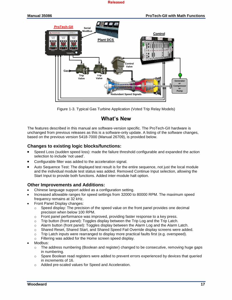
Figure 1-3. Typical Gas Turbine Application (Voted Trip Relay Models)
What’s New The features described in this manual are software-version specific. The ProTech-GII hardware is unchanged from previous releases as this is a software-only update. A listing of the software changes, based on the previous version 5418-7000 (Manual 26709), is provided below.
Changes to existing logic blocks/functions:
Speed Loss (sudden speed loss): made the failure threshold configurable and expanded the action selection to include ‘not used’.
Configurable filter was added to the acceleration signal.
Auto Sequence Test: The displayed test result is for the entire sequence, not just the local module and the individual module test status was added. Removed Continue Input selection, allowing the Start Input to provide both functions. Added inter-module halt option.
Other Improvements and Additions: Chinese language support added as a configuration setting. Increased allowable ranges for speed settings from 32000 to 80000 RPM. The maximum speed
frequency remains at 32 kHz. Front Panel Display changes:
o Speed display: The precision of the speed value on the front panel provides one decimal precision when below 100 RPM.
o Front panel performance was improved, providing faster response to a key press. o Trip button (front panel): Toggles display between the Trip Log and the Trip Latch. o Alarm button (front panel): Toggles display between the Alarm Log and the Alarm Latch. o Shared Reset, Shared Start, and Shared Speed Fail Override display screens were added. o Trip Latch inputs were rearranged to display more practical faults first (e.g. overspeed). o Filtering was added for the Home screen speed display.
Modbus: o The address numbering (Boolean and register) changed to be consecutive, removing huge gaps
in numbering. o Spare Boolean read registers were added to prevent errors experienced by devices that queried
in increments of 16. o Added pre-scaled values for Speed and Acceleration.
Released
Manual 35086 ProTech-GII with Math Functions
Woodward 18
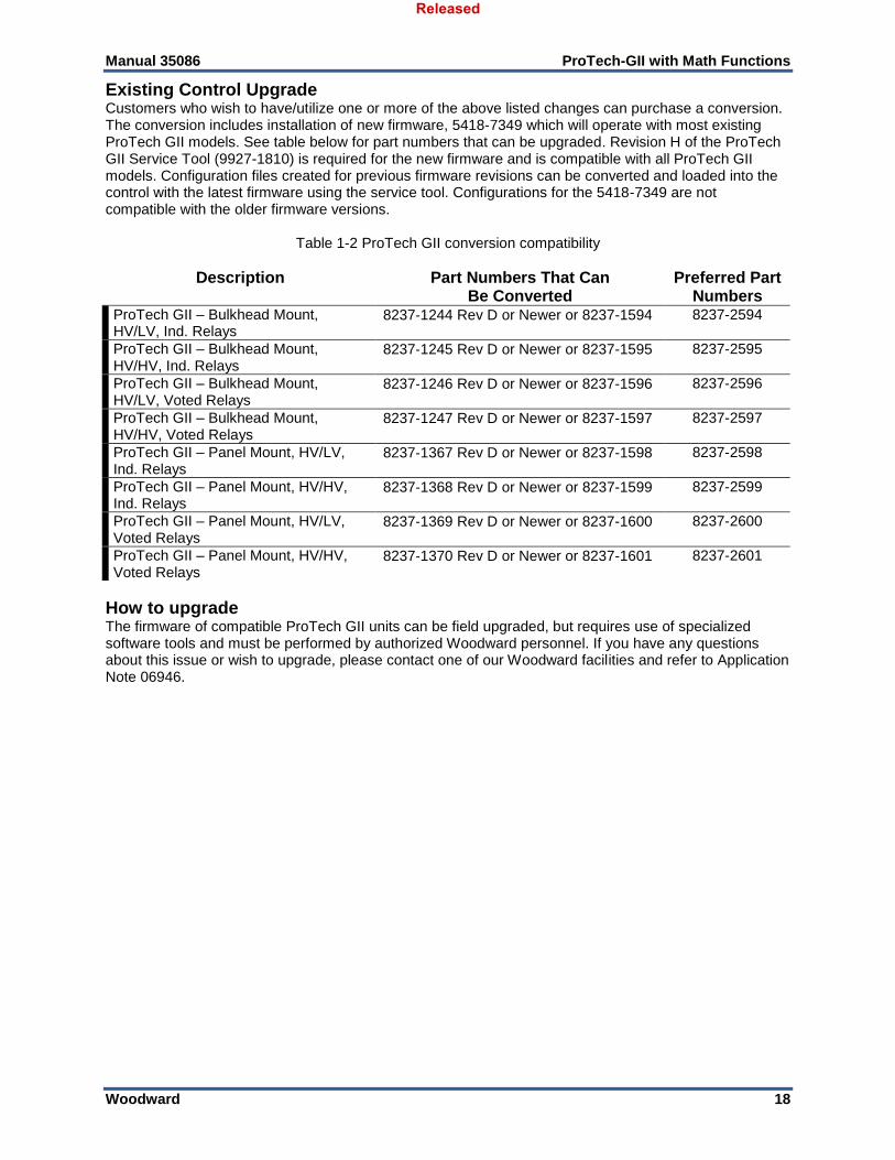
Existing Control Upgrade Customers who wish to have/utilize one or more of the above listed changes can purchase a conversion. The conversion includes installation of new firmware, 5418-7349 which will operate with most existing ProTech GII models. See table below for part numbers that can be upgraded. Revision H of the ProTech GII Service Tool (9927-1810) is required for the new firmware and is compatible with all ProTech GII models. Configuration files created for previous firmware revisions can be converted and loaded into the control with the latest firmware using the service tool. Configurations for the 5418-7349 are not compatible with the older firmware versions.
Table 1-2 ProTech GII conversion compatibility
Description Part Numbers That Can Be Converted
Preferred Part Numbers
ProTech GII – Bulkhead Mount, HV/LV, Ind. Relays
8237‐1244 Rev D or Newer or 8237-1594 8237-2594
ProTech GII – Bulkhead Mount, HV/HV, Ind. Relays
8237‐1245 Rev D or Newer or 8237-1595 8237-2595
ProTech GII – Bulkhead Mount, HV/LV, Voted Relays
8237‐1246 Rev D or Newer or 8237-1596 8237-2596
ProTech GII – Bulkhead Mount, HV/HV, Voted Relays
8237‐1247 Rev D or Newer or 8237-1597 8237-2597
ProTech GII – Panel Mount, HV/LV, Ind. Relays
8237‐1367 Rev D or Newer or 8237-1598 8237-2598
ProTech GII – Panel Mount, HV/HV, Ind. Relays
8237‐1368 Rev D or Newer or 8237-1599 8237-2599
ProTech GII – Panel Mount, HV/LV, Voted Relays
8237‐1369 Rev D or Newer or 8237-1600 8237-2600
ProTech GII – Panel Mount, HV/HV, Voted Relays
8237‐1370 Rev D or Newer or 8237-1601 8237-2601
How to upgrade The firmware of compatible ProTech GII units can be field upgraded, but requires use of specialized software tools and must be performed by authorized Woodward personnel. If you have any questions about this issue or wish to upgrade, please contact one of our Woodward facilities and refer to Application Note 06946.
Released

Manual 35086 ProTech-GII with Math Functions
Woodward 19
Chapter 2. Installation
Introduction This chapter provides instructions on how to mount and connect the ProTech-GII overspeed safety device into a system. Hardware dimensions, ratings, and jumper configurations are given to allow a customer to mount, wire, and configure the ProTech-GII package to a specific application. Electrical ratings, wiring requirements, and options are provided to allow for full integration of the ProTech-GII into a new or existing application.
Unpacking Before opening the shipping packaging, inspect the shipping container for damage and document any damage. Be careful when opening and removing the shipping container. You may retain the original shipping container for unit storage or return shipping for suggested refurbishment. (See Asset Management Chapter for storage details.) Be careful when unpacking the ProTech-GII system from the shipping container. The precautions called out in the Electrostatic Discharge Awareness section should be followed during unpacking, handling, installation and operation during maintenance. Once removed from the shipping packaging, check the device for signs of damage such as a bent or dented case and loose or broken parts. If damage is found, notify the shipper immediately.
Hardware Installation Procedure 1. Read and understand this manual completely before proceeding.
2. Create a site specific wiring diagram by referencing included wiring diagrams and constraints. Then perform mechanical and electrical installation following this chapter’s instructions.
3. Visual inspection
a. Verify that all mounting hardware is tightened and that no wires are pinched.
b. Verify that no wiring insulation is nicked or abraded.
c. Verify that all terminal blocks are installed and terminal screws are tight. Follow control wiring instructions for all terminal blocks.
d. If used, verify that speed sensors have been correctly installed, and have the correct clearance from the speed gear. Adjust if necessary. See manual 82510, Magnetic Pickups and Proximity Switches for Electronic Governors.
4. Apply power to each module, one at a time, and verify that each module boots up and its front panel screen displays turbine or equipment speed.
5. Enter the configuration mode and configure all settings to the specific application’s requirements.
6. Perform a full system checkout by verifying that all system trips, alarms, and test routines function correctly before starting the machinery/system.
7. When ready, start the turbine/machinery, following the equipment manufacturer’s recommended starting procedure.
Released
Manual 35086 ProTech-GII with Math Functions
Woodward 20
Enclosures
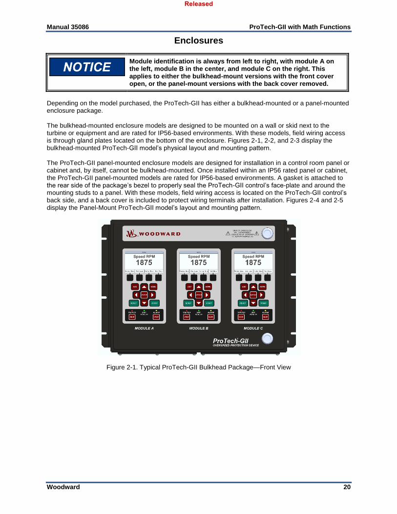
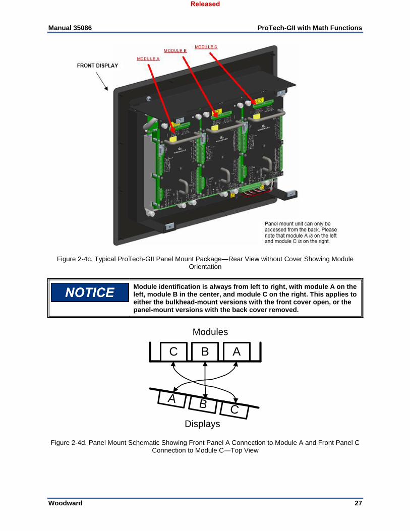
Module identification is always from left to right, with module A on the left, module B in the center, and module C on the right. This applies to either the bulkhead-mount versions with the front cover open, or the panel-mount versions with the back cover removed.
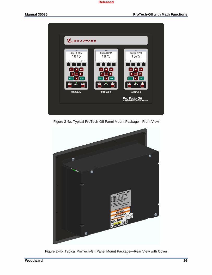
Depending on the model purchased, the ProTech-GII has either a bulkhead-mounted or a panel-mounted enclosure package. The bulkhead-mounted enclosure models are designed to be mounted on a wall or skid next to the turbine or equipment and are rated for IP56-based environments. With these models, field wiring access is through gland plates located on the bottom of the enclosure. Figures 2-1, 2-2, and 2-3 display the bulkhead-mounted ProTech-GII model’s physical layout and mounting pattern. The ProTech-GII panel-mounted enclosure models are designed for installation in a control room panel or cabinet and, by itself, cannot be bulkhead-mounted. Once installed within an IP56 rated panel or cabinet, the ProTech-GII panel-mounted models are rated for IP56-based environments. A gasket is attached to the rear side of the package’s bezel to properly seal the ProTech-GII control’s face-plate and around the mounting studs to a panel. With these models, field wiring access is located on the ProTech-GII control’s back side, and a back cover is included to protect wiring terminals after installation. Figures 2-4 and 2-5 display the Panel-Mount ProTech-GII model’s layout and mounting pattern.
Figure 2-1. Typical ProTech-GII Bulkhead Package—Front View
Released
Manual 35086 ProTech-GII with Math Functions
Woodward 21
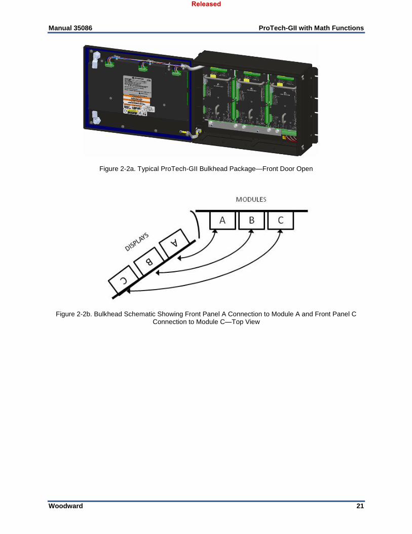
Figure 2-2a. Typical ProTech-GII Bulkhead Package—Front Door Open
Figure 2-2b. Bulkhead Schematic Showing Front Panel A Connection to Module A and Front Panel C
Connection to Module C—Top View
Released
Manual 35086 ProTech-GII with Math Functions
Woodward 22
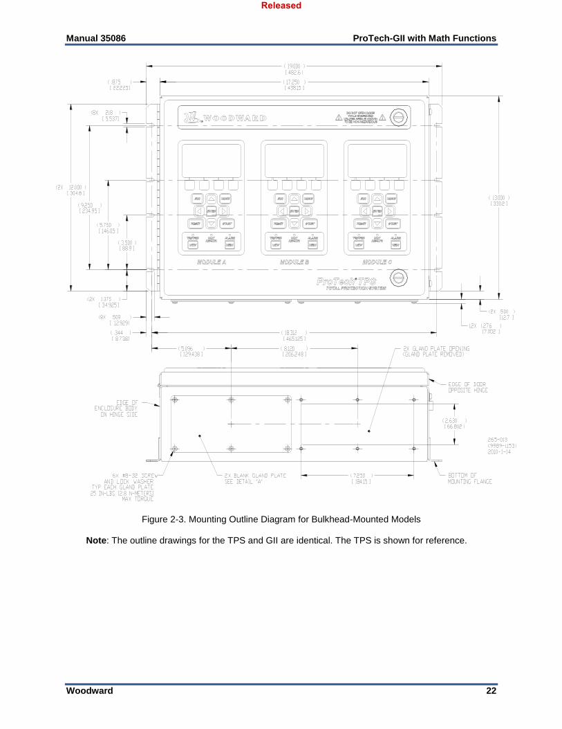
Figure 2-3. Mounting Outline Diagram for Bulkhead-Mounted Models
Note: The outline drawings for the TPS and GII are identical. The TPS is shown for reference.
Released
Manual 35086 ProTech-GII with Math Functions
Woodward 23
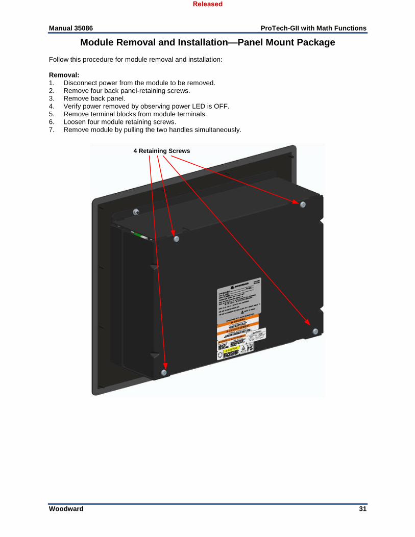
Module Removal and Installation—Bulkhead Mount Package
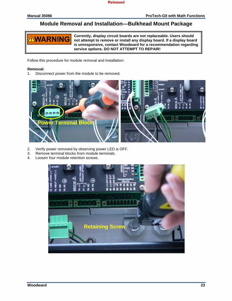
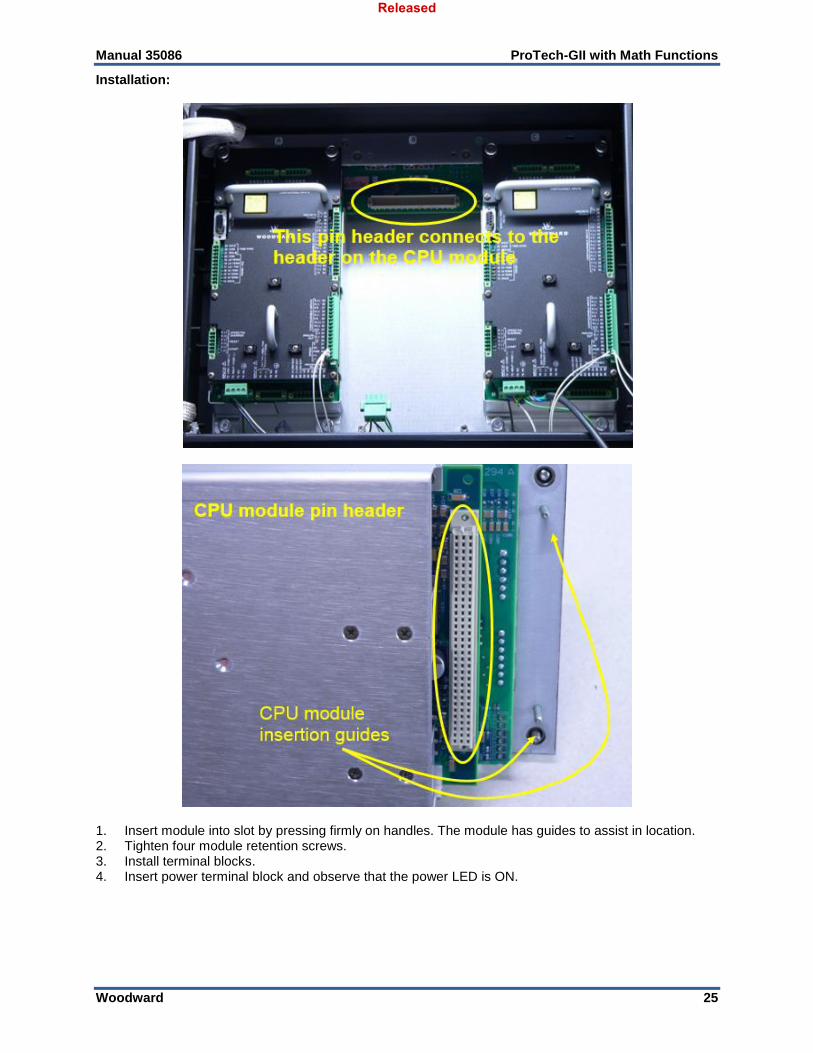
Currently, display circuit boards are not replaceable. Users should not attempt to remove or install any display board. If a display board is unresponsive, contact Woodward for a recommendation regarding service options. DO NOT ATTEMPT TO REPAIR!
Follow this procedure for module removal and installation: Removal: 1. Disconnect power from the module to be removed.
2. Verify power removed by observing power LED is OFF. 3. Remove terminal blocks from module terminals. 4. Loosen four module retention screws.
Power Terminal Block
Retaining Screw
Released
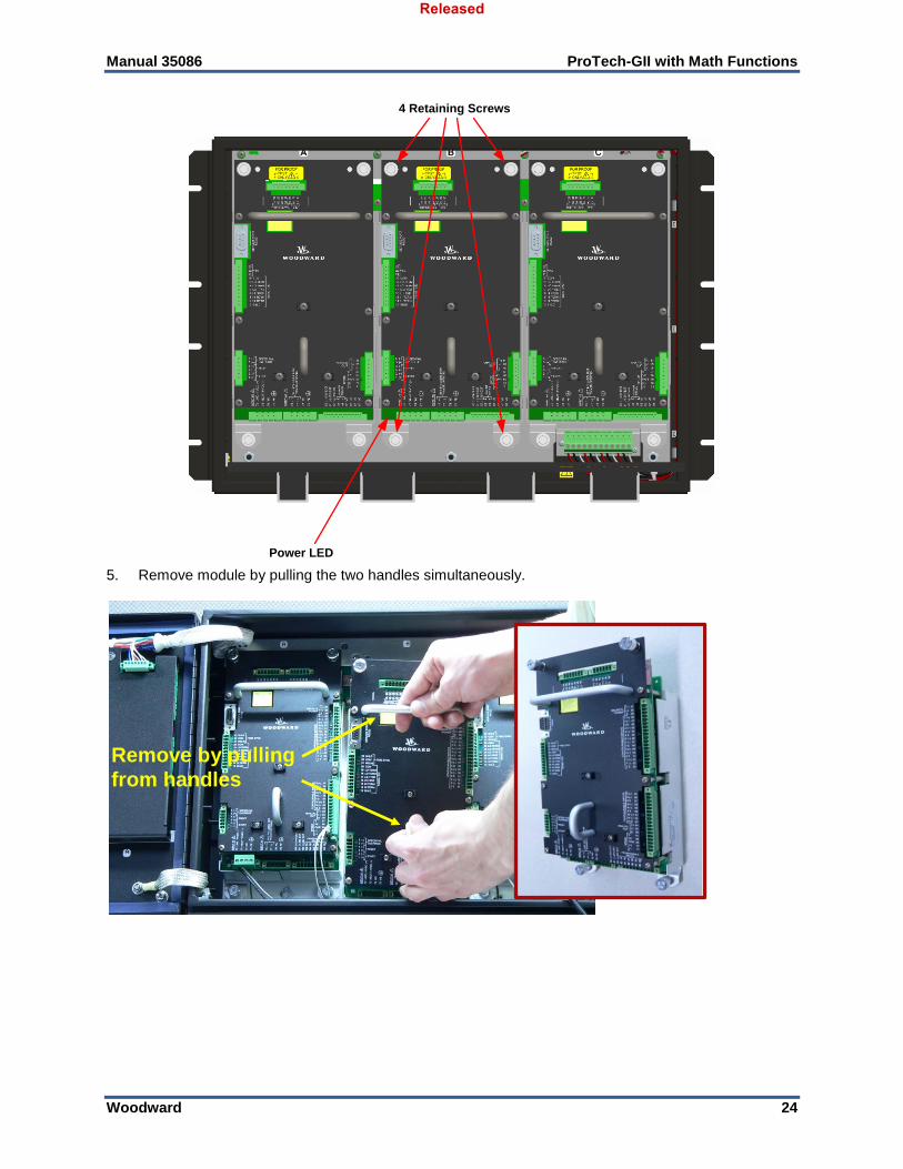
Manual 35086 ProTech-GII with Math Functions
Woodward 24
Power LED
4 Retaining Screws
5. Remove module by pulling the two handles simultaneously.
Remove by pulling
from handles
Released
Manual 35086 ProTech-GII with Math Functions
Woodward 25
Installation:
1. Insert module into slot by pressing firmly on handles. The module has guides to assist in location. 2. Tighten four module retention screws. 3. Install terminal blocks. 4. Insert power terminal block and observe that the power LED is ON.
Released
Manual 35086 ProTech-GII with Math Functions
Woodward 26
Figure 2-4a. Typical ProTech-GII Panel Mount Package—Front View
Figure 2-4b. Typical ProTech-GII Panel Mount Package—Rear View with Cover
Released
Manual 35086 ProTech-GII with Math Functions
Woodward 27
Figure 2-4c. Typical ProTech-GII Panel Mount Package—Rear View without Cover Showing Module Orientation
Module identification is always from left to right, with module A on the left, module B in the center, and module C on the right. This applies to either the bulkhead-mount versions with the front cover open, or the panel-mount versions with the back cover removed.
ABC
Displays
Modules
B CA
Figure 2-4d. Panel Mount Schematic Showing Front Panel A Connection to Module A and Front Panel C Connection to Module C—Top View
Released
Manual 35086 ProTech-GII with Math Functions
Woodward 28
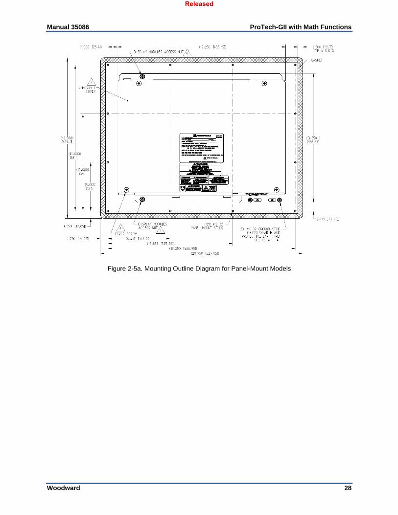
Figure 2-5a. Mounting Outline Diagram for Panel-Mount Models
Released
Manual 35086 ProTech-GII with Math Functions
Woodward 29
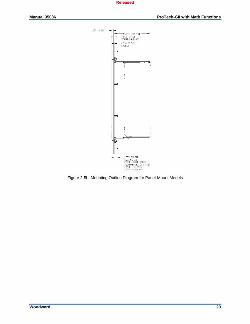
Figure 2-5b. Mounting Outline Diagram for Panel-Mount Models
Released
Manual 35086 ProTech-GII with Math Functions
Woodward 30
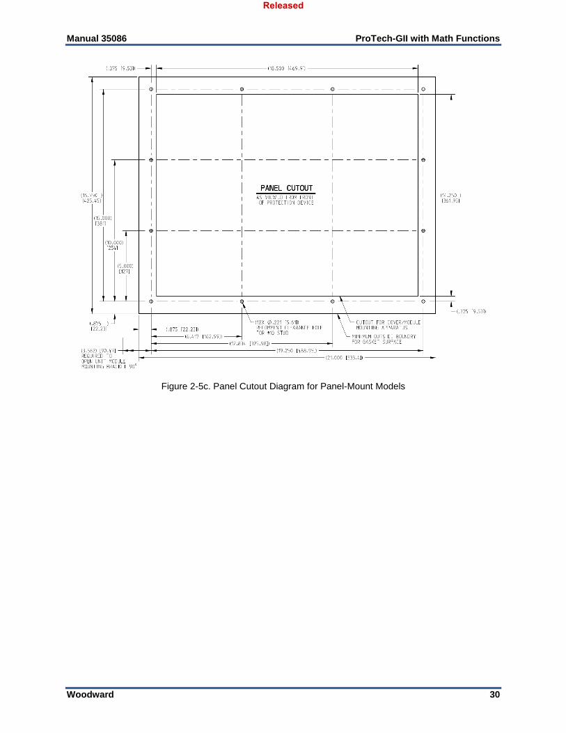
Figure 2-5c. Panel Cutout Diagram for Panel-Mount Models
Released
Manual 35086 ProTech-GII with Math Functions
Woodward 31
Module Removal and Installation—Panel Mount Package Follow this procedure for module removal and installation: Removal: 1. Disconnect power from the module to be removed. 2. Remove four back panel-retaining screws. 3. Remove back panel. 4. Verify power removed by observing power LED is OFF. 5. Remove terminal blocks from module terminals. 6. Loosen four module retaining screws. 7. Remove module by pulling the two handles simultaneously.
4 Retaining Screws
Released
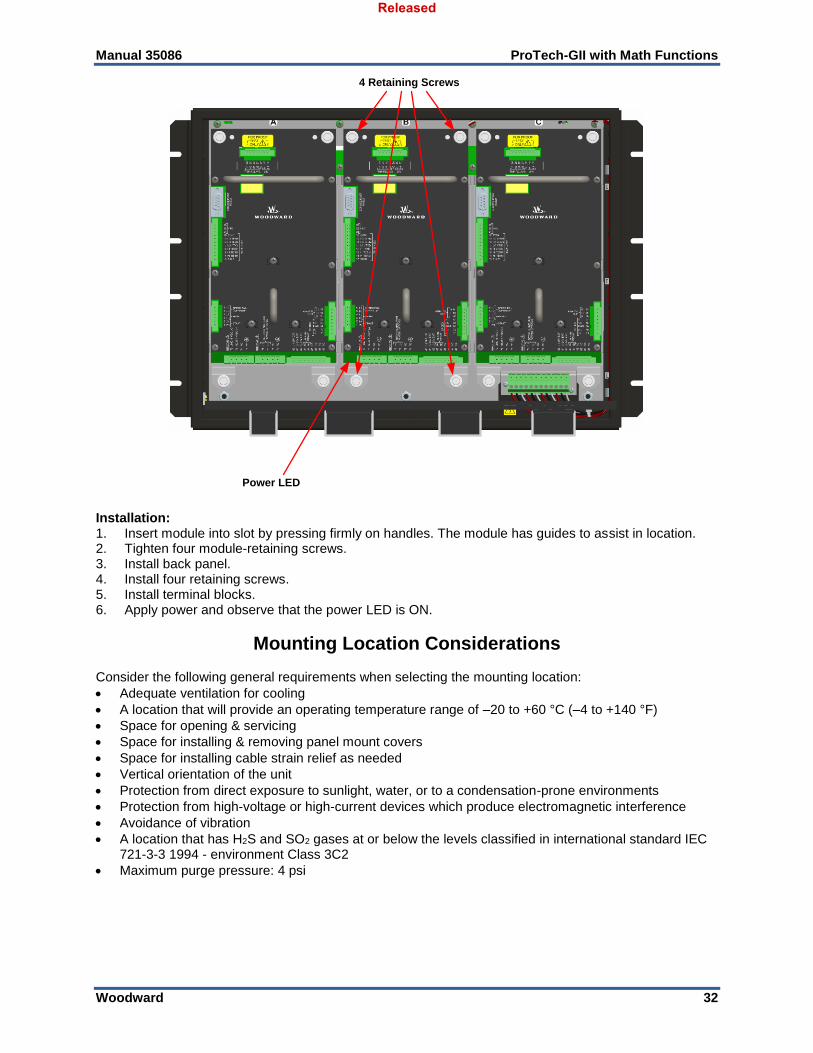
Manual 35086 ProTech-GII with Math Functions
Woodward 32
Power LED
4 Retaining Screws
Installation: 1. Insert module into slot by pressing firmly on handles. The module has guides to assist in location. 2. Tighten four module-retaining screws. 3. Install back panel. 4. Install four retaining screws. 5. Install terminal blocks. 6. Apply power and observe that the power LED is ON.
Mounting Location Considerations Consider the following general requirements when selecting the mounting location:
Adequate ventilation for cooling
A location that will provide an operating temperature range of –20 to +60 °C (–4 to +140 °F)
Space for opening & servicing
Space for installing & removing panel mount covers
Space for installing cable strain relief as needed
Vertical orientation of the unit
Protection from direct exposure to sunlight, water, or to a condensation-prone environments
Protection from high-voltage or high-current devices which produce electromagnetic interference
Avoidance of vibration
A location that has H2S and SO2 gases at or below the levels classified in international standard IEC 721-3-3 1994 - environment Class 3C2
Maximum purge pressure: 4 psi
Released

Manual 35086 ProTech-GII with Math Functions
Woodward 33
Table 2-1. Environmental Specifications
Operating Temperature: –20 to +60 °C (–4 to +140 °F)
Storage Temperature (nonoperational): –20 to +65 °C (–4 to +158 °F)
Relative Humidity: Up to 95% (non-condensing)
Vibration: 0.04 G2/Hz, 1.04 Grms, 10 to 500 Hz
Shock: 30 G, 11 ms half-sine pulse
Altitude: Up to 3000 meters above sea level
Enclosure (Bulkhead Mount Version): IP56 (per IEC 60529)
Enclosure (Panel Mount Version): IP56, installed in IP56 enclosure/cabinet
Weight (Bulkhead Mount Version): Approximately 26 lb (12 kg)
Weight (Panel Mount Version): Approximately 22 lb (10 kg)
Pollution Degree: 2 (per IEC 60664-1)
Overvoltage Category: II (per IEC 60664-1)
Electromagnetic Compatibility: Emissions: EN61000-6-4 Immunity: EN61000-6-2
Power Supply Requirements Each ProTech-GII system consists of three separate internal modules (A, B, C), and each of these three modules accept two input power sources. Depending on the ProTech-GII model purchased, the internal modules will accept either two high voltage (HV) input power sources or one HV input power source and one low voltage (LV) input power source. For reliability purposes, each ProTech-GII module will function normally with power sourced to either or both power supply inputs.
Power Supply Specifications
Table 2-2a. Low Voltage Input Specifications
Number of Inputs
2. Input range depends on model (see following tables):
2 High Voltage Inputs OR
1 High Voltage and 1 Low Voltage
Wiring Constraints
Each power supply input must be provided with its own breaker. This is to facilitate both on-line-removal of a module, and also to protect other power supplies from tripping while connected to a common input power circuit.
Table 2-2b. High Voltage Input Specifications
Voltage Input Range
90–264 Vac/47–63 Hz or 100–150 Vdc @ 30 W per module
Nominal 115 Vac / 240 Vac / 125 Vdc
Current Input Max*
0.5 A @ 90 Vac
0.22 A @ 264 Vac
0.25 Arms @ 110 Vdc
0.18 Arms @ 150 Vdc
Inrush Current 10 A at 115 Vac, 20 A @ 220 Vac
Reverse Polarity Protection
Yes, for DC connection
Interrupt Time 45 ms, when operating on one power supply only
Released

Manual 35086 ProTech-GII with Math Functions
Woodward 34
Table 2-2c. Power Supply Input Specifications
Voltage Input Range 18–32 Vdc @ 30 W per module
Nominal 24 Vdc
Current Input Max* 1.5 A @ 18 Vdc
1 A @ 32 Vdc
Inrush Current 0.05 A2s
Reverse Polarity Protection
Yes
Interrupt Time 3 ms, when operating on one power supply only
*Note that the input current specifications are for one module, measured with the other power supply input disconnected. With both power supply inputs connected, input current will never exceed the maximum specification. However, the two power supplies do not load share internally.
Internally Generated Limited Power Supply
Table 2-3 Relay Output Power Supply Specifications
Output Voltage 24 Vdc ±10%
Current Limit 500 mA
Each ProTech-GII module will function normally with power sourced to both or either power supply input independently, however Woodward recommends that both input power sources be used to improve system availability. Please refer to Table 1-1 for available ProTech-GII models.
Since the ProTech-GII is designed to detect a failure of either power supply, a continuous “Power Supply Fault Alarm” will be issued if a power supply is configured to alarm and a power-source is not connected to that supply.
Each ProTech-GII module requires a power source capable of a certain output voltage and current. In most cases, this power rating is stated in Volt-Amps (VA). The maximum VA of a source can be calculated by taking the rated output voltage times the maximum output current at that voltage. This value should be greater than or equal to the VA requirement listed.
Each power source must be provided with an external disconnecting means that is identifiable to the specific power supply (A, B, or C).
A PE (Protective Earth) ground wire for each of the high voltage power supplies must be connected to PE ground. The PE ground connection wire must originate and be connected to PE at the power source. The PE ground wire must follow the power wires to the applicable power input connector PE Ground pin, so that each HV input has a PE ground. The PE ground wire gauge must be capable of handling the same current as the individual power wiring.
Released
Manual 35086 ProTech-GII with Math Functions
Woodward 35
A PE (Protective Earth) ground wire for the enclosure must be provided and connected to PE Ground. At least one of the enclosure’s PE labeled connection points must have a wire going from the enclosure to a building PE ground point. This wire must be of sufficient gauge to handle the rated current of all the interposing relay wires or 1.5 mm2 (16 AWG), whichever is larger.
Input/Output Specifications
Speed Input Specifications
Table 2-4. General I/O Specifications
Number of Inputs 1, selectable as passive or active probe by front panel configuration
Speed Sensing Accuracy Accuracy: ±0.04% of current speed over –20 to +60 °C ambient temperature
Acceleration Sensing Accuracy and Range
Accuracy: ±1% of current speed Detectable over-acceleration range: 0 to 25000 RPM/s
Signal Cable Length Must be limited to 1500 ft /457 m (low capacitance 16 AWG / 1.3 mm²)
Internal Test Frequency Generator 6 Hz to 32 kHz, selectable in different test modes, see Chapter 4, Configuration and Operation
Table 2-5a. Passive Probe Specifications
Input Frequency Passive Probe (MPU): 100 Hz to 32 kHz
Input Amplitude 1 Vrms to 35 Vrms
Input Impedance 1.5 k
Isolation 500 Vac from input to chassis and input to all other circuits
Open Wire Detection MPU only > 7.5 kΩ
Table 2-5b. Active Probe Specifications
Input Frequency Active Probe (Proximity, Eddy Current): 0.5 Hz to 25 kHz
Input Amplitude Active Probe: 24 V probes
Probe Power 24 V ±10% @ 1 W, probe power switched on only in active probe mode.
Internal Pull-up Resistor 10 k, input suitable for use with open collector probe outputs (see Note)
Input Threshold (Vlow) < 2 V
Input Threshold (Vhigh) > 4 V
Isolation 500 Vac from input to chassis and input to all other circuits
Released
Manual 35086 ProTech-GII with Math Functions
Woodward 36
Each speed input is designed to operate from its own speed probe. Do not connect a speed probe to more than one input. This will compromise the ability of the ProTech-GII to sense open wire (passive mode only) and interfere with the minimum amplitude sensitivity and accuracy.
When using open collector probes, verify that the signal is being read properly at higher frequencies (>10 kHz). Long cable lengths can significantly reduce the signal strength at higher frequencies. In
this case, add an external pull-up resistor of approximately 2 k (0.25 W) from terminals 70 to 69 and verify that the signal is read properly by the ProTech-GII.
Shielded cable is required when connecting to the speed input.
Relay Specifications
Table 2-6a. Independent Trip Relay Specifications
Number of Channels 2 (actuated simultaneously)
Output Type SPST Solid-state, Normally Open
Current Rating 1 A
Voltage Rating 24 V (32 V max)
Isolation 500 Vac from output to chassis and output to all other circuits
Signal Cable Length Must be limited to 1000 ft / 305 m (low capacitance 16 AWG / 1.3 mm² pair)
Table 2-6b. Voted Trip Relay Specifications
Number of Channels 2 (both channels actuated simultaneously), see wiring and installation
Output Type Form C, dual SPDT
Contact Rating 8 A @ 220 Vac / 8 A @ 24 Vdc
Max. Switching Voltage 220 Vac / 150 Vdc
Max. Switching Power 2000 VA / 192 W
Isolation 1500 Vac from contact to chassis and contacts to all other circuits
Table 2-7. Alarm Relay Specifications
Output Type SPST Solid-state, Normally Open
Current Rating 1 A
Voltage Rating 24 V (32 V max)
Isolation 500 Vac from output to chassis and output to all other circuits
Signal Cable Length Must be limited to 1000 ft / 305 m (low capacitance 16 AWG / 1.3 mm²)
Released
Manual 35086 ProTech-GII with Math Functions
Woodward 37
Dedicated Discrete Input Specifications
Table 2-8. Dedicated Discrete Input Specifications
Number of Channels 3, (Start, Reset, Speed Fail Override)
Input Thresholds <= 8 Vdc = “OFF”
>= 16 Vdc = “ON”
Input Current 3 mA ±5% at 24 V (for externally power wiring, see, Chapter 2)
Wetting Current Supply 24 V at 2 W available (see installation diagrams, Chapter 2). This power supply is current limited.
Max Input Voltage 32 V (for externally power wiring, see, Chapter 2)
Isolation 500 Vac from output to chassis and output to all other circuits
I/O Execution Rate 4 ms
Table 2-9. Analog Output Specifications
Number of Channels 1
Output Type 4–20 mA, isolated
Max Current Output 25 mA
Accuracy ±0.1% at 25 °C, ±0.5% over temperature
Resolution 12 bit
I/O Execution Rate 4 ms
Response Time < 2 ms (2 to 20 mA)
Min Current Output 0 mA
Min Resistive 0
Max Resistive Load 500 at 25 mA
Isolation 500 Vac from output to chassis and output to all other circuits
Signal Cable Length Must be limited to 1000 ft / 305 m (low capacitance 16 AWG / 1.3 mm²)
Table 2-10. Serial Port (RS-232/RS-485) Specifications
Number of Ports 1
Comm Type RS-232/RS-485, user selectable
Termination Resistor RS-485 on board, terminal block selectable
Isolation 500 Vac from output to chassis and output to all other circuits
Signal Cable Length Must be limited to 1500 ft / 305 m RS-485 (low capacitance 16 AWG / 1.3 mm²), 50 ft / 15 m RS-232
Released
Manual 35086 ProTech-GII with Math Functions
Woodward 38
Shielded Wiring All shielded cable must be twisted conductor pairs with either a foil or a braided shield. A braided shield is preferred and highly recommended. All analog and communication signal lines should be shielded to prevent picking up stray signals from adjacent equipment. Connect the shields as shown in the control wiring diagram (Figure 2-7). Wire exposed beyond the shield must not exceed 50 mm (2 inches). The shield termination should be done with the shield by opening the braid and pulling the wires through, not with an added wire. If a wire is used it must be the largest gauge accepted by the shield lug terminal. The other end of the shield must be left open or grounded through a capacitor and insulated from any other conductor. Do not run shielded signal wires with other wires carrying large currents or high voltages. See Woodward manual 50532, EMI Control in Electronic Governing Systems, for more information. Installations with severe electromagnetic interference (EMI) may require relay and discrete input wiring to be shielded, conduits and/or double shielded wire may be needed, or other precautions may have to be taken. These additional precautions may be implemented in any installation. Contact Woodward for more information.
Control Wiring Guidelines
Electrical Connections
EXPLOSION HAZARD—Do not connect or disconnect while circuit is live unless area is known to be non-hazardous.
Plug-in screw-type terminal blocks are used to connect field wiring to each ProTech-GII module and to the trip (interposing) relay contacts. The size of the field wiring to the ProTech system should be between 1.5 and 6 mm² (16 and 10 AWG) for power supply wiring and between 0.3 and 4 mm² (22 and 12 AWG) for all other I/O wiring. Wires for the all the pluggable I/O terminal blocks should be stripped at 8 mm (0.3 inch). Torque and screwdriver requirements are listed below.
The screw lug terminal blocks are designed to flatten stranded wire. Do not tin (solder) the wires strands that terminate at the ProTech Terminal Blocks. If the wire strands are soldered together, the solder will cold flow and shrink over time causing the connection to become intermittent or disconnected.
Woodward recommends the following for ProTech-GII:
Stranded bare copper wire (unless gaseous Sulfur compounds are present) at the wire ends
Stranded copper wire with individually tin plated strands at the wire ends
Hollow ferrules at the wire ends
Use single wire per terminal. There are enough terminals provided for all I/O wiring
Released
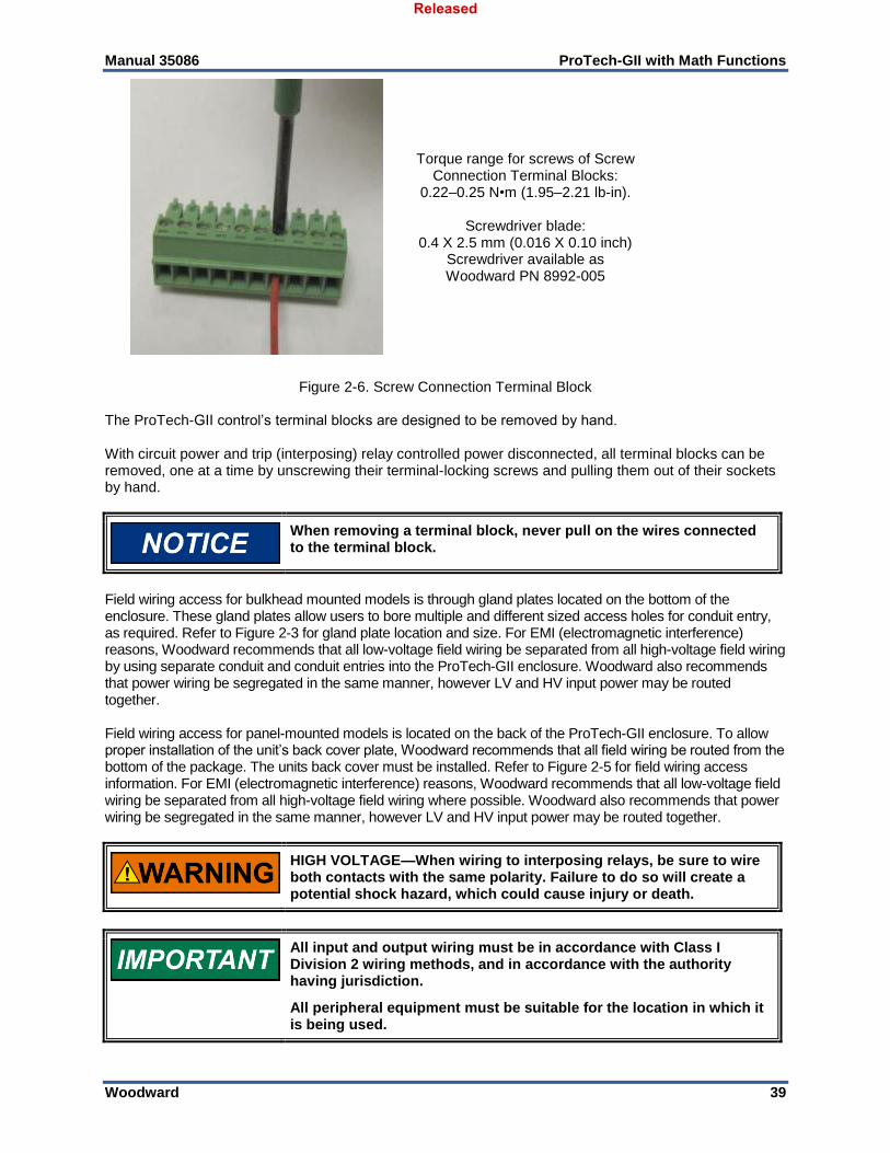
Manual 35086 ProTech-GII with Math Functions
Woodward 39
Torque range for screws of Screw Connection Terminal Blocks:
0.22–0.25 N•m (1.95–2.21 lb-in).
Screwdriver blade: 0.4 X 2.5 mm (0.016 X 0.10 inch)
Screwdriver available as Woodward PN 8992-005
Figure 2-6. Screw Connection Terminal Block The ProTech-GII control’s terminal blocks are designed to be removed by hand. With circuit power and trip (interposing) relay controlled power disconnected, all terminal blocks can be removed, one at a time by unscrewing their terminal-locking screws and pulling them out of their sockets by hand.
When removing a terminal block, never pull on the wires connected to the terminal block.
Field wiring access for bulkhead mounted models is through gland plates located on the bottom of the enclosure. These gland plates allow users to bore multiple and different sized access holes for conduit entry, as required. Refer to Figure 2-3 for gland plate location and size. For EMI (electromagnetic interference) reasons, Woodward recommends that all low-voltage field wiring be separated from all high-voltage field wiring by using separate conduit and conduit entries into the ProTech-GII enclosure. Woodward also recommends that power wiring be segregated in the same manner, however LV and HV input power may be routed together. Field wiring access for panel-mounted models is located on the back of the ProTech-GII enclosure. To allow proper installation of the unit’s back cover plate, Woodward recommends that all field wiring be routed from the bottom of the package. The units back cover must be installed. Refer to Figure 2-5 for field wiring access information. For EMI (electromagnetic interference) reasons, Woodward recommends that all low-voltage field wiring be separated from all high-voltage field wiring where possible. Woodward also recommends that power wiring be segregated in the same manner, however LV and HV input power may be routed together.
HIGH VOLTAGE—When wiring to interposing relays, be sure to wire both contacts with the same polarity. Failure to do so will create a potential shock hazard, which could cause injury or death.
All input and output wiring must be in accordance with Class I Division 2 wiring methods, and in accordance with the authority having jurisdiction.
All peripheral equipment must be suitable for the location in which it is being used.
Released
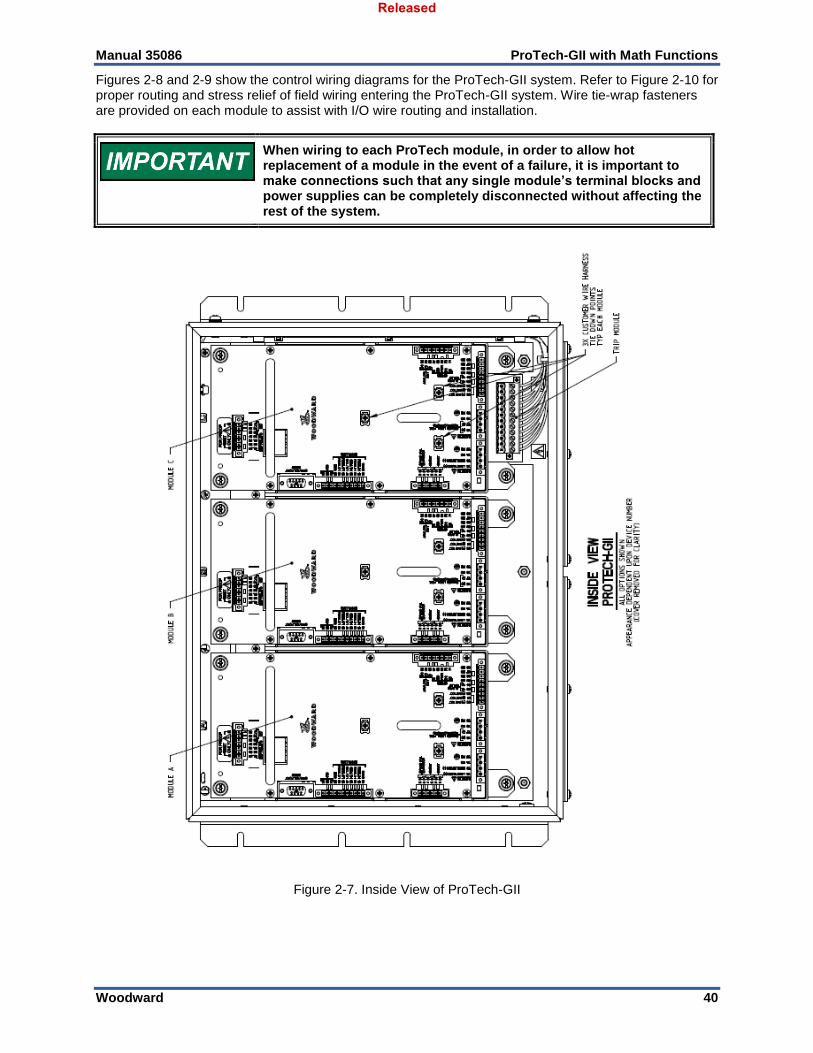
Manual 35086 ProTech-GII with Math Functions
Woodward 40
Figures 2-8 and 2-9 show the control wiring diagrams for the ProTech-GII system. Refer to Figure 2-10 for proper routing and stress relief of field wiring entering the ProTech-GII system. Wire tie-wrap fasteners are provided on each module to assist with I/O wire routing and installation.
When wiring to each ProTech module, in order to allow hot replacement of a module in the event of a failure, it is important to make connections such that any single module’s terminal blocks and power supplies can be completely disconnected without affecting the rest of the system.
Figure 2-7. Inside View of ProTech-GII
Released
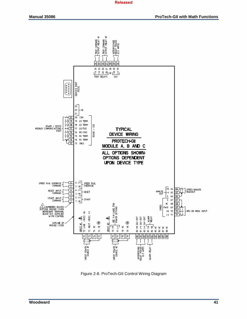
Manual 35086 ProTech-GII with Math Functions
Woodward 41
Figure 2-8. ProTech-GII Control Wiring Diagram
Released
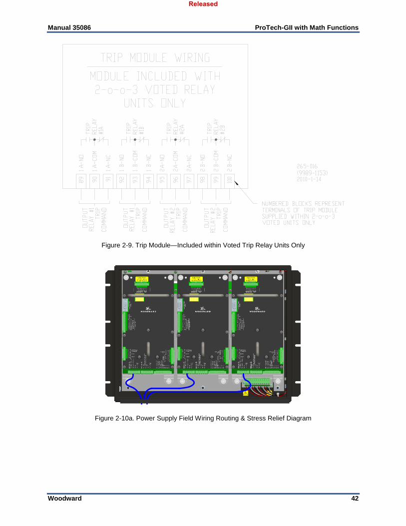
Manual 35086 ProTech-GII with Math Functions
Woodward 42
Figure 2-9. Trip Module—Included within Voted Trip Relay Units Only
Figure 2-10a. Power Supply Field Wiring Routing & Stress Relief Diagram
Released
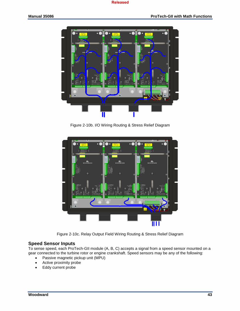
Manual 35086 ProTech-GII with Math Functions
Woodward 43
Figure 2-10b. I/O Wiring Routing & Stress Relief Diagram
Figure 2-10c. Relay Output Field Wiring Routing & Stress Relief Diagram
Speed Sensor Inputs To sense speed, each ProTech-GII module (A, B, C) accepts a signal from a speed sensor mounted on a gear connected to the turbine rotor or engine crankshaft. Speed sensors may be any of the following:
Passive magnetic pickup unit (MPU)
Active proximity probe
Eddy current probe
Released
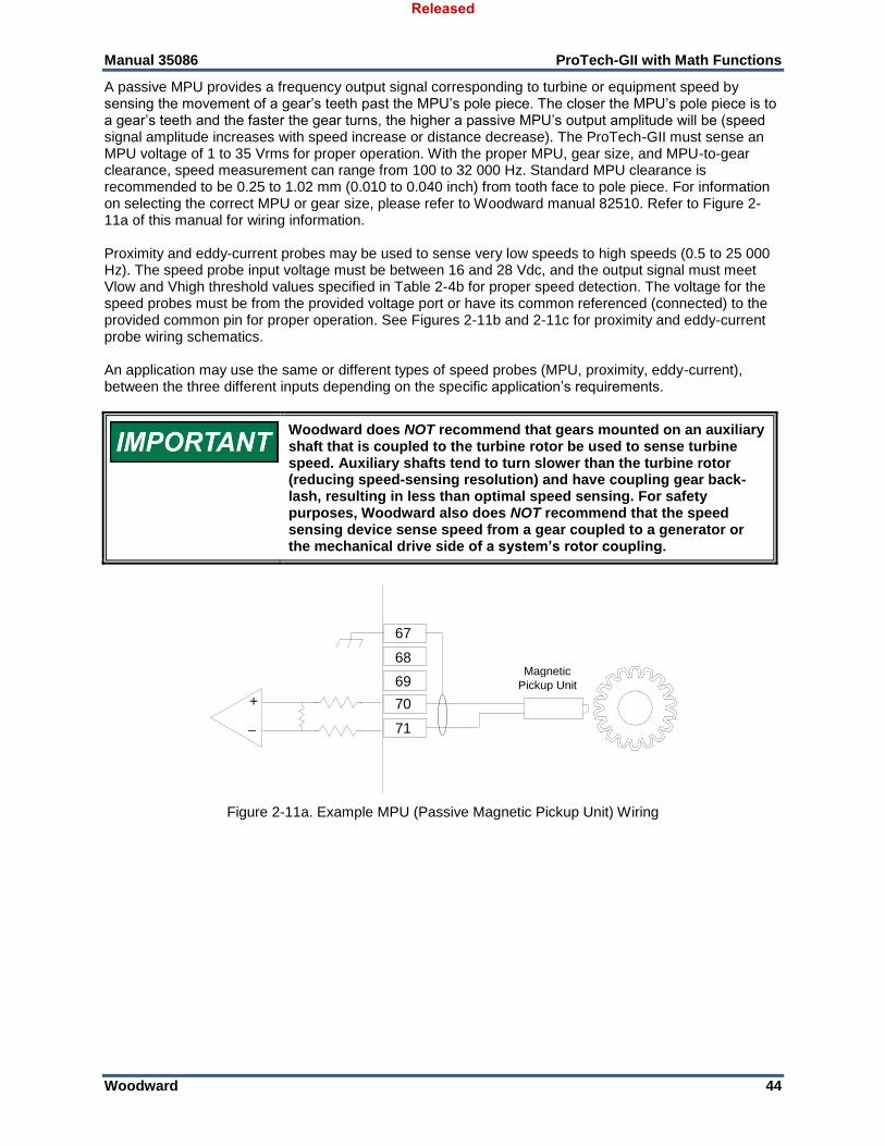
Manual 35086 ProTech-GII with Math Functions
Woodward 44
A passive MPU provides a frequency output signal corresponding to turbine or equipment speed by sensing the movement of a gear’s teeth past the MPU’s pole piece. The closer the MPU’s pole piece is to a gear’s teeth and the faster the gear turns, the higher a passive MPU’s output amplitude will be (speed signal amplitude increases with speed increase or distance decrease). The ProTech-GII must sense an MPU voltage of 1 to 35 Vrms for proper operation. With the proper MPU, gear size, and MPU-to-gear clearance, speed measurement can range from 100 to 32 000 Hz. Standard MPU clearance is recommended to be 0.25 to 1.02 mm (0.010 to 0.040 inch) from tooth face to pole piece. For information on selecting the correct MPU or gear size, please refer to Woodward manual 82510. Refer to Figure 2-11a of this manual for wiring information. Proximity and eddy-current probes may be used to sense very low speeds to high speeds (0.5 to 25 000 Hz). The speed probe input voltage must be between 16 and 28 Vdc, and the output signal must meet Vlow and Vhigh threshold values specified in Table 2-4b for proper speed detection. The voltage for the speed probes must be from the provided voltage port or have its common referenced (connected) to the provided common pin for proper operation. See Figures 2-11b and 2-11c for proximity and eddy-current probe wiring schematics. An application may use the same or different types of speed probes (MPU, proximity, eddy-current), between the three different inputs depending on the specific application’s requirements.
Woodward does NOT recommend that gears mounted on an auxiliary shaft that is coupled to the turbine rotor be used to sense turbine speed. Auxiliary shafts tend to turn slower than the turbine rotor (reducing speed-sensing resolution) and have coupling gear back-lash, resulting in less than optimal speed sensing. For safety purposes, Woodward also does NOT recommend that the speed sensing device sense speed from a gear coupled to a generator or the mechanical drive side of a system’s rotor coupling.
Figure 2-11a. Example MPU (Passive Magnetic Pickup Unit) Wiring
67
68
69
70
71
+
_
Magnetic Pickup Unit
Released
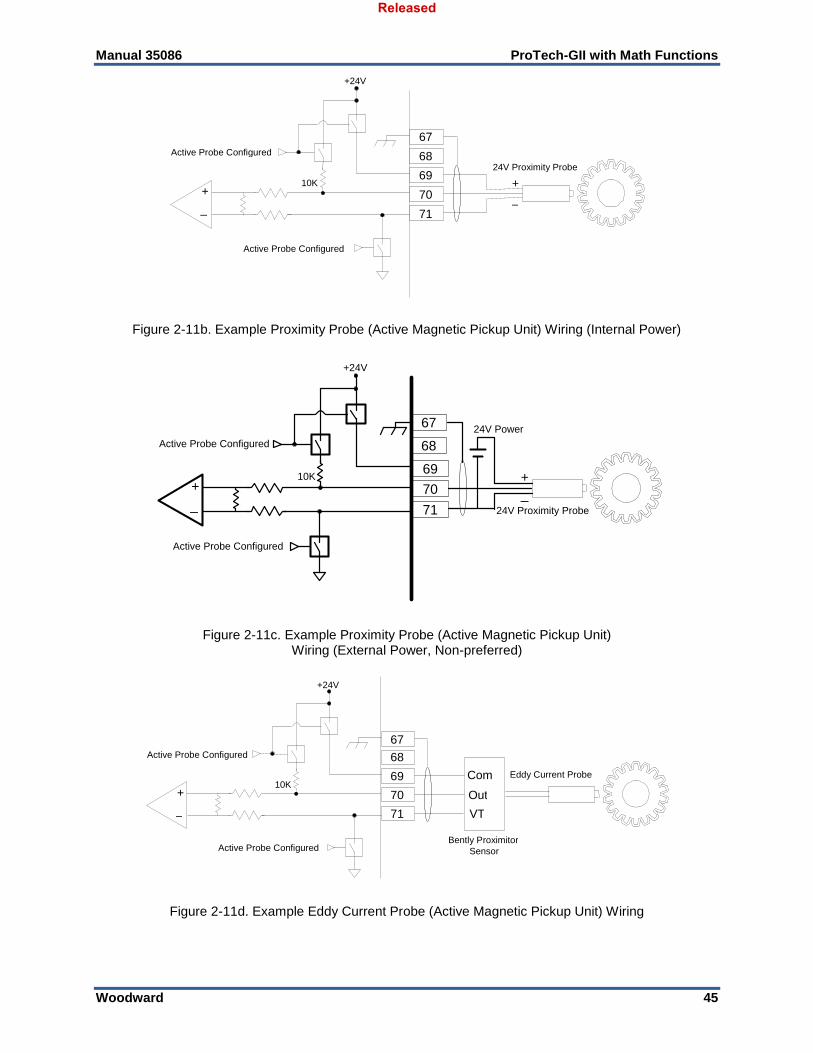
Manual 35086 ProTech-GII with Math Functions
Woodward 45
Figure 2-11b. Example Proximity Probe (Active Magnetic Pickup Unit) Wiring (Internal Power)
69
70
71
+
_ 24V Proximity Probe
+24V
Active Probe Configured
Active Probe Configured
10K +
_
67
68
24V Power
Figure 2-11c. Example Proximity Probe (Active Magnetic Pickup Unit)
Wiring (External Power, Non-preferred)
Figure 2-11d. Example Eddy Current Probe (Active Magnetic Pickup Unit) Wiring
67
68
69
70
71
+
_
24V Proximity Probe
+24V
Active Probe Configured
Active Probe Configured
10K +
_
67
68
69
70
71
+
_
Eddy Current Probe
+24V
Active Probe Configured
Active Probe Configured
10K
VT
Com
Out
Bently Proximitor Sensor
Released
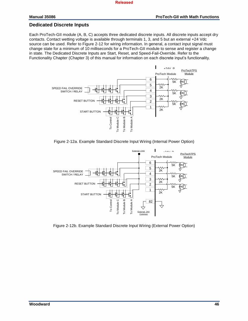
Manual 35086 ProTech-GII with Math Functions
Woodward 46
Dedicated Discrete Inputs Each ProTech-GII module (A, B, C) accepts three dedicated discrete inputs. All discrete inputs accept dry contacts. Contact wetting voltage is available through terminals 1, 3, and 5 but an external +24 Vdc source can be used. Refer to Figure 2-12 for wiring information. In general, a contact input signal must change state for a minimum of 10 milliseconds for a ProTech-GII module to sense and register a change in state. The Dedicated Discrete Inputs are Start, Reset, and Speed-Fail-Override. Refer to the Functionality Chapter (Chapter 3) of this manual for information on each discrete input’s functionality.
Figure 2-12a. Example Standard Discrete Input Wiring (Internal Power Option)
Figure 2-12b. Example Standard Discrete Input Wiring (External Power Option)
START BUTTON
SPEED FAIL OVERRIDE
SWITCH / RELAY
ProTechTPS
Module
6
5
4
3
2
1
+24V_P
2K
2K
2K
5K
5K
5K
To
Mo
du
le B
To
Mo
du
le C
To
Co
ntr
ol
To
Mo
du
le A
RESET BUTTON
START BUTTON
SPEED FAIL OVERRIDE
SWITCH / RELAY
ProTechTPS
Module
6
5
4
3
2
1
+24V_P
2K
2K
2K
5K
5K
5K
To
Mo
du
le B
To
Mo
du
le C
To
Co
ntr
ol
To
Mo
du
le A
RESET BUTTON
External +24V
External 24V
Common
82
ProTech Module
ProTech Module
Released
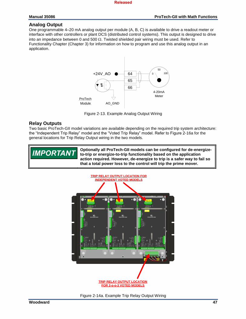
Manual 35086 ProTech-GII with Math Functions
Woodward 47
Analog Output One programmable 4–20 mA analog output per module (A, B, C) is available to drive a readout meter or interface with other controllers or plant DCS (distributed control systems). This output is designed to drive
into an impedance between 0 and 500 . Twisted shielded pair wiring must be used. Refer to Functionality Chapter (Chapter 3) for information on how to program and use this analog output in an application.
Figure 2-13. Example Analog Output Wiring
Relay Outputs Two basic ProTech-GII model variations are available depending on the required trip system architecture: the “Independent Trip Relay” model and the “Voted Trip Relay” model. Refer to Figure 2-16a for the general locations for Trip Relay Output wiring in the two models.
Optionally all ProTech-GII models can be configured for de-energize-to-trip or energize-to-trip functionality based on the application action required. However, de-energize to trip is a safer way to fail so that a total power loss to the control will trip the prime mover.
TRIP RELAY OUTPUT LOCATION
FOR 2-o-o-3 VOTED MODELS
TRIP RELAY OUTPUT LOCATION FOR
INDEPENDENT VOTED MODELS
Figure 2-14a. Example Trip Relay Output Wiring
64
65
66 4-20mA Meter
ProTech Module
+24V_AO 0 100 50
AO_GND
Released
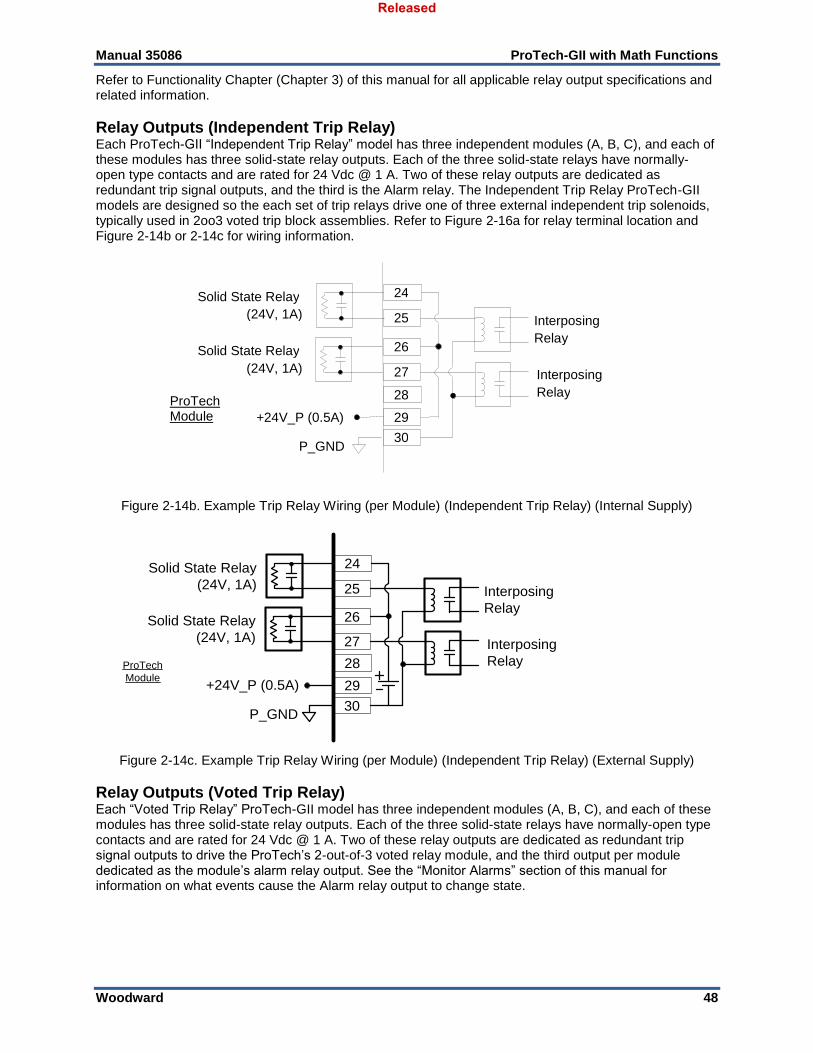
Manual 35086 ProTech-GII with Math Functions
Woodward 48
Refer to Functionality Chapter (Chapter 3) of this manual for all applicable relay output specifications and related information.
Relay Outputs (Independent Trip Relay) Each ProTech-GII “Independent Trip Relay” model has three independent modules (A, B, C), and each of these modules has three solid-state relay outputs. Each of the three solid-state relays have normally-open type contacts and are rated for 24 Vdc @ 1 A. Two of these relay outputs are dedicated as redundant trip signal outputs, and the third is the Alarm relay. The Independent Trip Relay ProTech-GII models are designed so the each set of trip relays drive one of three external independent trip solenoids, typically used in 2oo3 voted trip block assemblies. Refer to Figure 2-16a for relay terminal location and Figure 2-14b or 2-14c for wiring information.
Figure 2-14b. Example Trip Relay Wiring (per Module) (Independent Trip Relay) (Internal Supply)
24
25
26
27
28
29
30
Solid State Relay
(24V, 1A)
Solid State Relay
(24V, 1A)
P_GND
+24V_P (0.5A)
Interposing
Relay
Interposing
RelayProTech
Module
Figure 2-14c. Example Trip Relay Wiring (per Module) (Independent Trip Relay) (External Supply)
Relay Outputs (Voted Trip Relay) Each “Voted Trip Relay” ProTech-GII model has three independent modules (A, B, C), and each of these modules has three solid-state relay outputs. Each of the three solid-state relays have normally-open type contacts and are rated for 24 Vdc @ 1 A. Two of these relay outputs are dedicated as redundant trip signal outputs to drive the ProTech’s 2-out-of-3 voted relay module, and the third output per module dedicated as the module’s alarm relay output. See the “Monitor Alarms” section of this manual for information on what events cause the Alarm relay output to change state.
24
25
26
27
28
29
30
Solid State Relay
(24V, 1A)
Solid State Relay
(24V, 1A)
P_GND
+24V_P (0.5A)
Interposing
Relay
Interposing
Relay ProTech Module
Released
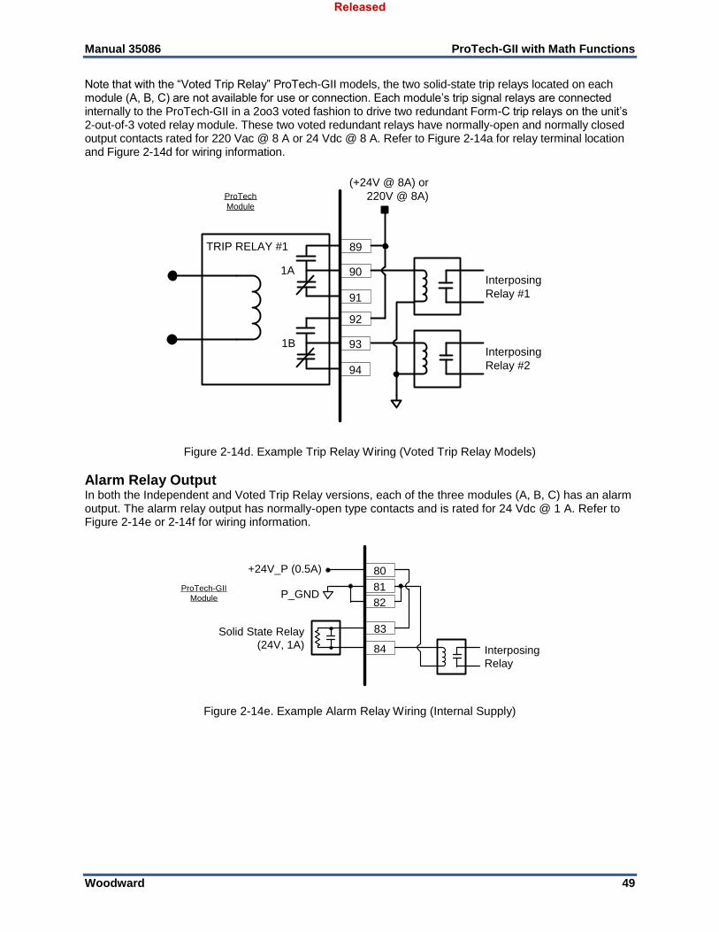
Manual 35086 ProTech-GII with Math Functions
Woodward 49
Note that with the “Voted Trip Relay” ProTech-GII models, the two solid-state trip relays located on each module (A, B, C) are not available for use or connection. Each module’s trip signal relays are connected internally to the ProTech-GII in a 2oo3 voted fashion to drive two redundant Form-C trip relays on the unit’s 2-out-of-3 voted relay module. These two voted redundant relays have normally-open and normally closed output contacts rated for 220 Vac @ 8 A or 24 Vdc @ 8 A. Refer to Figure 2-14a for relay terminal location and Figure 2-14d for wiring information.
89
90
91
(+24V @ 8A) or
220V @ 8A)
Interposing
Relay #1
Interposing
Relay #2
ProTech
Module
92
93
94
TRIP RELAY #1
1A
1B
Figure 2-14d. Example Trip Relay Wiring (Voted Trip Relay Models)
Alarm Relay Output In both the Independent and Voted Trip Relay versions, each of the three modules (A, B, C) has an alarm output. The alarm relay output has normally-open type contacts and is rated for 24 Vdc @ 1 A. Refer to Figure 2-14e or 2-14f for wiring information.
83
84
Solid State Relay
(24V, 1A)
P_GND
+24V_P (0.5A)
Interposing
Relay
80
81
82
ProTech-GII
Module
Figure 2-14e. Example Alarm Relay Wiring (Internal Supply)
Released
Manual 35086 ProTech-GII with Math Functions
Woodward 50
Chapter 3. Functionality
Introduction The ProTech-GII is an overspeed safety device designed to safely shut down steam, gas, and hydro turbines of all sizes upon sensing an overspeed or over-acceleration event. This device accurately monitors turbine rotor speed and acceleration via active or passive MPUs (magnetic pickups) and issues a shutdown command to the turbine’s trip valve(s) or corresponding trip system. Depending on the system design, the ProTech-GII can be purchased with two dual redundant trip relay outputs using a 2-out-of-3 voted architecture, or with three independent non-voted trip relay outputs. Individual alarm relays, 4–20 mA speed readouts, and Modbus communications make this overspeed device easy to integrate into any turbine safety system.
Features
Fault Tolerant Design Each ProTech-GII consists of three independent modules referred to as A, B and C. Each module accepts one speed input and three dedicated-function discrete inputs. Each module also has one alarm relay output and one analog output for the sensed speed output. The ProTech-GII comes in two basic models—the “Independent Trip Relay” models and the “Voted Trip Relay” models. This relates to the trip signal configuration. The differences between these two models and their application are discussed in detail in the Product Models section of this chapter. Each of the three ProTech-GII modules A, B, and C are fully fault isolated from each other such that faults in one module do not affect any of the other modules. The modules are connected via a safety certified CAN network which allows the sharing of all module input information (speed and discrete inputs) and module configuration information. The ProTech-GII’s configuration copy function also utilizes this network to transfer/copy configuration file from one module to another. Normally, each module is configured to operate with identical configuration settings. Monitoring logic is used to confirm that all modules are running the same exact configuration as the other modules and will issue an alarm if it detects that one or more of the modules are not running identical configurations. Thus if a change to configuration setting is made to one module while the ProTech-GII is in normal operation and the turbine or equipment is on-line and operating normally, each module will issue an alarm. Once all configuration settings are the same again, this alarm can be reset. In special cases that require a different configuration to be installed in each module, the Configuration Compare alarm can be disabled. The ProTech-GII overspeed device is certified for use in IEC-61508 SIL-3 based applications. This overspeed device’s triple modular design allows users to replace any of its modules (A, B, C) while the monitored turbine or equipment is on-line and operating normally. This is also referred to as ‘hot replacement.’ Ease of replacement is enhanced by the unit’s backplane plug-and-operate structure and its module-to-module program copying function. Each ProTech-GII module shares its input values (speed, acceleration, discrete inputs) and its trip and alarm latch information with the other two modules. Users can then optionally configure the module’s trip and alarm logic to use or not use the shared input and latch information. This type of redundancy allows users the choice of using one, two or three speed sensors and connecting to (wiring to) three modules, two modules or only one module and using the sharing and voting logic to manage logic in all three modules. Refer to Figure 3-1 for more information on module to module sharing logic.
Released
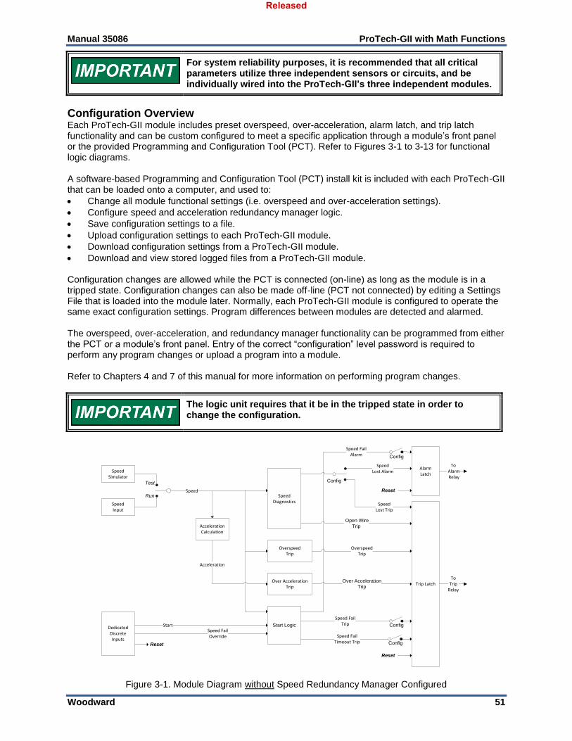
Manual 35086 ProTech-GII with Math Functions
Woodward 51
For system reliability purposes, it is recommended that all critical parameters utilize three independent sensors or circuits, and be individually wired into the ProTech-GII’s three independent modules.
Configuration Overview Each ProTech-GII module includes preset overspeed, over-acceleration, alarm latch, and trip latch functionality and can be custom configured to meet a specific application through a module’s front panel or the provided Programming and Configuration Tool (PCT). Refer to Figures 3-1 to 3-13 for functional logic diagrams. A software-based Programming and Configuration Tool (PCT) install kit is included with each ProTech-GII that can be loaded onto a computer, and used to:
Change all module functional settings (i.e. overspeed and over-acceleration settings).
Configure speed and acceleration redundancy manager logic.
Save configuration settings to a file.
Upload configuration settings to each ProTech-GII module.
Download configuration settings from a ProTech-GII module.
Download and view stored logged files from a ProTech-GII module. Configuration changes are allowed while the PCT is connected (on-line) as long as the module is in a tripped state. Configuration changes can also be made off-line (PCT not connected) by editing a Settings File that is loaded into the module later. Normally, each ProTech-GII module is configured to operate the same exact configuration settings. Program differences between modules are detected and alarmed. The overspeed, over-acceleration, and redundancy manager functionality can be programmed from either the PCT or a module’s front panel. Entry of the correct “configuration” level password is required to perform any program changes or upload a program into a module. Refer to Chapters 4 and 7 of this manual for more information on performing program changes.
The logic unit requires that it be in the tripped state in order to change the configuration.
Config
SpeedInput
Open Wire
Trip
Over Acceleration
Trip Trip Latch
AlarmLatch
Start LogicDedicatedDiscreteInputs
OverspeedTrip
StartSpeed FailOverride
OverspeedTrip
Speed FailTrip
Speed FailTimeout Trip
AccelerationCalculation
ToTrip
Relay
SpeedLost Alarm
Speed FailAlarm
SpeedLost Trip
SpeedSimulator
SpeedDiagnostics
Test
Run
Acceleration
Reset
To Alarm Relay
Reset
Over AccelerationTrip
Config
Config
Config
Speed
Reset
Figure 3-1. Module Diagram without Speed Redundancy Manager Configured
Released
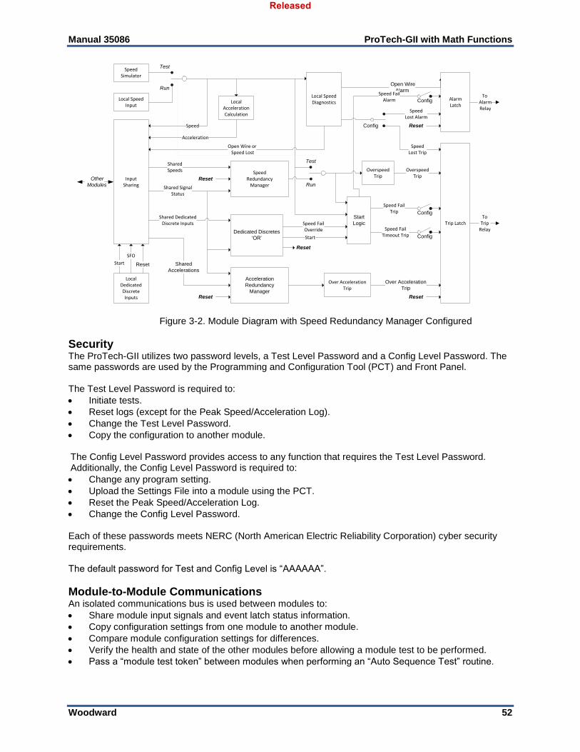
Manual 35086 ProTech-GII with Math Functions
Woodward 52
Config
Other
Modules
Local SpeedInput
Open Wire
Alarm
Over Acceleration
Trip
Trip Latch
AlarmLatch
Start
Logic
SpeedRedundancy
Manager
Acceleration
Redundancy
Manager
LocalDedicatedDiscreteInputs
OverspeedTripInput
Sharing Shared SignalStatus
SharedSpeeds
Shared
Accelerations
Shared DedicatedDiscrete Inputs
Dedicated Discretes
‘OR’
Start
SFO
Reset
OverspeedTrip
Speed FailTrip
Speed FailTimeout Trip
LocalAccelerationCalculation
ToTrip
Relay
SpeedLost Alarm
Speed FailAlarm
SpeedLost Trip
SpeedSimulator
Test
Run
Local SpeedDiagnostics
Test
Run
Open Wire or Speed Lost
Acceleration
Speed
Start
Speed FailOverride
Reset
To Alarm Relay
Reset
Reset
Reset
Reset
Over AccelerationTrip
Config
Config
Config
Figure 3-2. Module Diagram with Speed Redundancy Manager Configured
Security The ProTech-GII utilizes two password levels, a Test Level Password and a Config Level Password. The same passwords are used by the Programming and Configuration Tool (PCT) and Front Panel. The Test Level Password is required to:
Initiate tests.
Reset logs (except for the Peak Speed/Acceleration Log).
Change the Test Level Password.
Copy the configuration to another module. The Config Level Password provides access to any function that requires the Test Level Password. Additionally, the Config Level Password is required to:
Change any program setting.
Upload the Settings File into a module using the PCT.
Reset the Peak Speed/Acceleration Log.
Change the Config Level Password. Each of these passwords meets NERC (North American Electric Reliability Corporation) cyber security requirements. The default password for Test and Config Level is “AAAAAA”.
Module-to-Module Communications An isolated communications bus is used between modules to:
Share module input signals and event latch status information.
Copy configuration settings from one module to another module.
Compare module configuration settings for differences.
Verify the health and state of the other modules before allowing a module test to be performed.
Pass a “module test token” between modules when performing an “Auto Sequence Test” routine.
Released
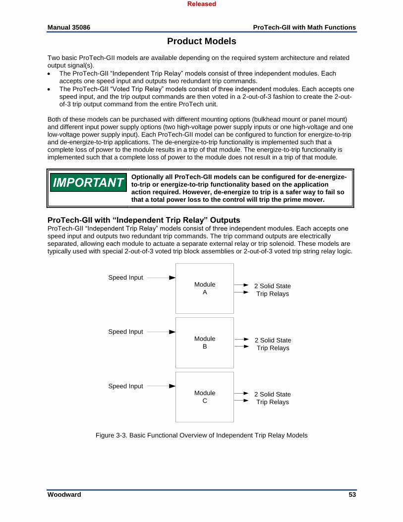
Manual 35086 ProTech-GII with Math Functions
Woodward 53
Product Models Two basic ProTech-GII models are available depending on the required system architecture and related output signal(s).
The ProTech-GII “Independent Trip Relay” models consist of three independent modules. Each accepts one speed input and outputs two redundant trip commands.
The ProTech-GII “Voted Trip Relay” models consist of three independent modules. Each accepts one speed input, and the trip output commands are then voted in a 2-out-of-3 fashion to create the 2-out-of-3 trip output command from the entire ProTech unit.
Both of these models can be purchased with different mounting options (bulkhead mount or panel mount) and different input power supply options (two high-voltage power supply inputs or one high-voltage and one low-voltage power supply input). Each ProTech-GII model can be configured to function for energize-to-trip and de-energize-to-trip applications. The de-energize-to-trip functionality is implemented such that a complete loss of power to the module results in a trip of that module. The energize-to-trip functionality is implemented such that a complete loss of power to the module does not result in a trip of that module.
Optionally all ProTech-GII models can be configured for de-energize-to-trip or energize-to-trip functionality based on the application action required. However, de-energize to trip is a safer way to fail so that a total power loss to the control will trip the prime mover.
ProTech-GII with “Independent Trip Relay” Outputs ProTech-GII “Independent Trip Relay” models consist of three independent modules. Each accepts one speed input and outputs two redundant trip commands. The trip command outputs are electrically separated, allowing each module to actuate a separate external relay or trip solenoid. These models are typically used with special 2-out-of-3 voted trip block assemblies or 2-out-of-3 voted trip string relay logic.
Module
B
Module
C
2 Solid State
Trip Relays
Speed InputModule
A
Speed Input
Speed Input
2 Solid State
Trip Relays
2 Solid State
Trip Relays
Figure 3-3. Basic Functional Overview of Independent Trip Relay Models
Released
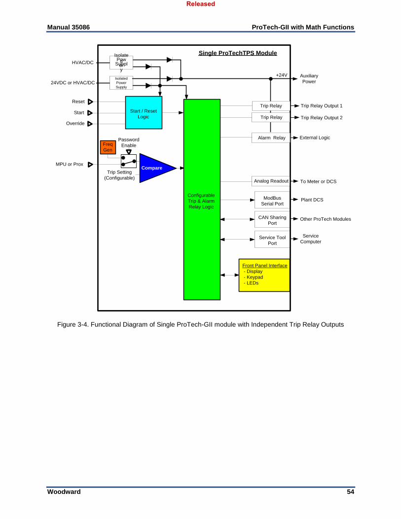
Manual 35086 ProTech-GII with Math Functions
Woodward 54
24VDC or HVAC/DC
HVAC/DC
Single ProTechTPS Module
Trip Relay
+24V
MPU or Prox
Reset
Start
Override
Trip Setting
(Configurable)
CAN Sharing
Port
Compare
ModBus
Serial Port
Auxiliary
Power
Plant DCS
Other ProTech Modules
Trip Relay
External Logic
Start / Reset
Logic
Configurable
Trip & Alarm
Relay Logic
Alarm Relay
Service Tool
Port
Service
Computer
To Meter or DCSAnalog Readout
Password
EnableFreq
Gen
Isolated
Power
Supply
Isolate
dPow
erSuppl
y
Front Panel Interface
- Display
- Keypad
- LEDs
Trip Relay Output 1
Trip Relay Output 2
Figure 3-4. Functional Diagram of Single ProTech-GII module with Independent Trip Relay Outputs
Released
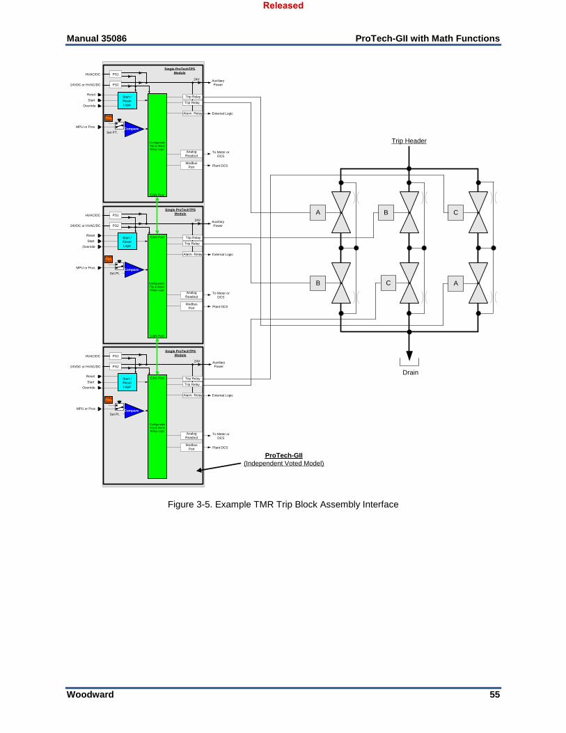
Manual 35086 ProTech-GII with Math Functions
Woodward 55
24VDC or HVAC/DC
HVAC/DC
Single ProTechTPS
Module
Trip Relay
24V
MPU or Prox
Reset
Start
Override
Set PT.Compare
Trip RelayStart /
Reset
Logic
Configurable
Trip & Alarm
Relay Logic
Freq
Gen
PS2
PS1
24VDC or HVAC/DC
HVAC/DC
Single ProTechTPS
Module
Trip Relay
24V
MPU or Prox
Reset
Start
Override
Set Pt.Compare
Trip RelayStart /
Reset
Logic
Configurable
Trip & Alarm
Relay Logic
Alarm RelayFreq
Gen
PS2
PS1
24VDC or HVAC/DC
HVAC/DC
Single ProTechTPS
Module
Trip Relay
24V
MPU or Prox
Reset
Start
Override
Set Pt.Compare
Trip RelayStart /
Reset
Logic
Configurable
Trip & Alarm
Relay Logic
Freq
Gen
PS2
PS1
Trip Header
Drain
B
A B C
A
Auxiliary
Power
Plant DCS
External Logic
To Meter or
DCS
Modbus
Port
Analog
Readout
Alarm Relay
Plant DCS
External Logic
To Meter or
DCS
Modbus
Port
Analog
Readout
Auxiliary
Power
Auxiliary
Power
Alarm Relay
Plant DCS
External Logic
To Meter or
DCS
Modbus
Port
Analog
Readout
ProTech-GII
(Independent Voted Model)
CAN Port
CAN Port
CAN Port
CAN Port
C
Figure 3-5. Example TMR Trip Block Assembly Interface
Released
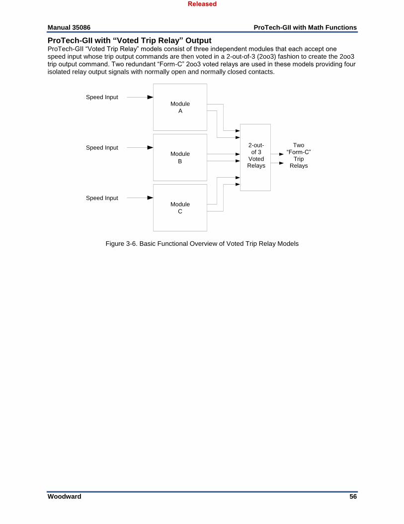
Manual 35086 ProTech-GII with Math Functions
Woodward 56
ProTech-GII with “Voted Trip Relay” Output ProTech-GII “Voted Trip Relay” models consist of three independent modules that each accept one speed input whose trip output commands are then voted in a 2-out-of-3 (2oo3) fashion to create the 2oo3 trip output command. Two redundant “Form-C” 2oo3 voted relays are used in these models providing four isolated relay output signals with normally open and normally closed contacts.
Figure 3-6. Basic Functional Overview of Voted Trip Relay Models
2-out- of 3
Voted Relays
Module B
Module C
Two “Form-C”
Trip Relays
Speed Input Module
A
Speed Input
Speed Input
Released
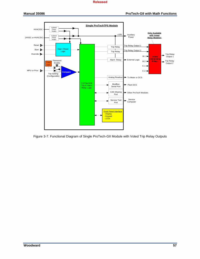
Manual 35086 ProTech-GII with Math Functions
Woodward 57
24VDC or HVAC/DC
HVAC/DC
Single ProTechTPS Module
Trip Relay
+24V
MPU or Prox
Reset
Start
Override
Trip Setting
(Configurable)
CAN Sharing
Port
Compare
ModBus
Serial Port
Auxiliary
Power
Plant DCS
Other ProTech Modules
Trip Relay
External Logic
Start / Reset
Logic
Configurable
Trip & Alarm
Relay Logic
Alarm Relay
Service Tool
Port
Service
Computer
To Meter or DCSAnalog Readout
Password
EnableFreq
Gen
Isolated
Power
Supply
Isolated
Power
Supply
Voted
Interposing
Relays
Trip Relay
Output 1B-1
B-2
C-1
C-2
Trip Relay
Output 2
Only Available
with Voted
Relay Models!!
Front Panel Interface
- Display
- Keypad
- LEDs
Trip Relay Output 1
Trip Relay Output 2
Figure 3-7. Functional Diagram of Single ProTech-GII Module with Voted Trip Relay Outputs
Released
Manual 35086 ProTech-GII with Math Functions
Woodward 58
24VDC or HVAC/DC
HVAC/DC
Single ProTechTPS
Module
Trip Relay
24V
MPU or Prox
Reset
Start
Override
Set PT.Compare
Trip RelayStart /
Reset
Logic
Configurable
Trip & Alarm
Relay Logic
Prog Relay
Freq
Gen
24VDC or HVAC/DC
HVAC/DC
Single ProTechTPS
Module
Trip Relay
24V
MPU or Prox
Reset
Start
Override
Set Pt.Compare
Trip RelayStart /
Reset
Logic
Configurable
Trip & Alarm
Relay Logic
Prog Relay
Freq
Gen
24VDC or HVAC/DC
HVAC/DC
Single ProTechTPS
Module
Trip Relay
24V
MPU or Prox
Reset
Start
Override
Set Pt.Compare
Trip RelayStart /
Reset
Logic
Configurable
Trip & Alarm
Relay Logic
Alarm Relay
Freq
Gen
Trip Header
Drain
TSVoted
Relays
CAN Port
CAN Port
CAN Port
Figure 3-8. Simplex Trip Block Assembly
Released
Manual 35086 ProTech-GII with Math Functions
Woodward 59
24VDC or HVAC/DC
HVAC/DC
Single ProTechTPS
Module
Trip Relay
24V
MPU or Prox
Reset
Start
Override
Set PT.Compare
Trip RelayStart /
Reset
Logic
Configurable
Trip & Alarm
Relay Logic
Alarm Relay
Freq
Gen
24VDC or HVAC/DC
HVAC/DC
Single ProTechTPS
Module
Trip Relay
24V
MPU or Prox
Reset
Start
Override
Set Pt.Compare
Trip RelayStart /
Reset
Logic
Configurable
Trip & Alarm
Relay Logic
Alarm Relay
Freq
Gen
24VDC or HVAC/DC
HVAC/DC
Single ProTechTPS
Module
Trip Relay
24V
MPU or Prox
Reset
Start
Override
Set Pt.Compare
Trip RelayStart /
Reset
Logic
Configurable
Trip & Alarm
Relay Logic
Alarm Relay
Freq
Gen
Trip Header
Drain
A B
Voted
Relays
CAN Port
CAN Port
CAN Port
Hand
Valve
Hand
Valve
Figure 3-9. Dual Redundant Trip Block Assembly
Inputs and Outputs
Input Redundancy Each ProTech-GII module shares its input values (speed, acceleration, discrete inputs) and its trip and alarm latch information with the other two modules. Users can then optionally configure the module’s trip and alarm logic to use or not use the shared input and latch information. Configurable redundancy manager blocks are available for the speed and acceleration signal redundancy logic. Optionally one or all of the module’s discrete inputs can be configured with “ORed” logic. This type of redundancy allows users the choice of using one, two or three speed sensors and connecting to (wiring to) three modules, two modules or only one module and using the sharing and voting logic to manage logic in all three modules.
Released
Manual 35086 ProTech-GII with Math Functions
Woodward 60
Speed Sensor Inputs Each module has one speed input which can be programmed to accept a passive MPU (magnetic pickup unit) or an active speed sensor (proximity probe signal or an eddy current probe signal). When configured as an MPU signal input, special MPU open-wire detection circuitry is used to validate that the MPU is properly connected before equipment operation, and special loss-of-speed detection logic is used to validate speed sensor functionality during equipment operation. Depending on the module’s program settings, a loss of speed signal or open-wire detection will result in a trip or alarm condition.
MPU open-wire detection logic and associated trip/alarm action is only utilized when the speed input is configured as a “passive” probe.
When configured as a passive probe input, the speed sensor circuitry will sense MPU signals within the voltage range of 1—35 Vrms. When configured as an active probe input or eddy current probe input, a 24 V power supply is provided to power the probe, but an isolated external supply may be used instead, if it is referenced correctly. The Number of Gear Teeth and Gear Ratio are configured to convert the frequency input from the speed probe to the unit speed.
The Number of Gear Teeth and Gear Ratio must match the actual unit hardware or speed sensing and all association protection and functionality will not work correctly.
If the ProTech-GII’s speed redundancy manager is not configured for use, then each module simply uses its local speed sensor signal, and compares it to the overspeed setpoint to determine an overspeed event. If the ProTech-GII’s speed redundancy manager is configured for use then each module uses its local sensed speed signal and the shared speed signals from the other two modules to select/vote the signal to use in its overspeed detection logic. The speed redundancy manager can be configured to vote the median, highest, or lowest speed signal to use in its overspeed detection logic, and can be configured to change its voting logic based on the number of healthy speed probes/signals. Note that the Speed Redundancy Manager allows users to elect to use three speed sensing probes, two speed sensing probes, or only one speed sensing probe, depending on the specific application’s requirements. If only two probes are used, then the third module can be configured to only use and vote on the shared speed signals (from the other modules) to use in its overspeed and over-acceleration detection logic. Although not recommended, if only one probe is used, then the second and third modules can be configured to only use and vote on the shared speed signal (from the first module) to use in their overspeed and over-acceleration detection logic. If the unit is configured for only two probes (or just one probe), there will be a configuration mismatch and associated alarm. This alarm can be disabled in the Configuration Management Menu.
Dedicated Discrete Inputs Each ProTech-GII module (A, B, C) accepts three dedicated discrete inputs. The Dedicated Discrete Inputs are Start, Reset and Speed-Fail-Override. Each module can be configured to use only its local discrete input signals (start, reset, and speed fail override) or the “ORed” result of its local discrete inputs and the other two modules’ discrete inputs. This is useful if only one or two discrete contacts are available from a specific circuit or application.
Released

Manual 35086 ProTech-GII with Math Functions
Woodward 61
Start Input This contact input is used as part of the Start Logic “Speed Fail Timeout Trip” function. When this function is enabled, closing the Start contact will start the Speed Fail Timeout timer. This is an edge-triggered signal and re-selecting Start will re-start this timer. Refer to the Start Logic section below for additional details. If it is desired to use one module’s contact inputs to also “Start” the other modules Speed Fail Timeout Trip functions, each module’s Boolean Input Manager logic function can be configured to do so. Each module’s Boolean Input Manager function can be configured to accept, only its local Start contact input, or a specific module’s Start contact input, or all modules’ Start contact inputs. Note—Since the Start button on the front of the module is physically connected to the Start contact input, sharing the Start contact input will also share the Start button. Reset Input This contact is used to clear/reset all local module trips and alarms events from the trip and alarm latches. If it is desired to use one module’s contact inputs to also “Reset” the other modules trip and alarm latches, each module’s Boolean Input Manager logic function can be configured to do so. Each module’s Boolean Input Manager function can be configured to accept, only its local Reset contact input, or a specific module’s Reset contact input, or all modules’ Reset contact inputs. Note—The Reset button on the front of the module is a local module command only and cannot be connected to nor affect the “ORed” Reset contact input logic on other modules. Speed-Fail-Override Input This is used as part of the Start Logic “Speed Fail Trip” function. When this function is enabled, closing the Speed-Fail-Override contact overrides the Speed Fail Trip. This is a level sensitive trigger so the contact must remain closed to prevent the Speed Fail Trip until speed is greater than the speed fail setpoint. Refer to the Start Logic section below for additional details. If it is desired to use one module’s contact inputs to also function as the “Speed Fail Override Input” for the other modules, the module’s Boolean Input Manager logic function can be configured to do so. Each module’s Boolean Input Manager function can be configured to accept, only it’s local Speed-Fail-Override contact input, or a specific module’s Speed-Fail-Override contact input, or all modules’ Speed-Fail-Override contact inputs.
Alarm Relay Output Each module has one alarm relay output. This output is a normally open contact. When an alarm is present, the contact is open.
Analog Output A single 4–20 mA output is provided on each module to indicate the speed sensed by that module. The 4–20 mA range can be configured to any speed range desired. The accuracy of the analog output is better than ±0.5% of 20 mA over the temperature range of the product. Shielded twisted pair cable is required when connecting to the analog outputs.
Overspeed and Over-Acceleration Detection Logic Each ProTech-GII includes overspeed and over-acceleration functionality and can be configured to meet specific application overspeed and over-acceleration requirements. The ProTech-GII senses speed and then compares the sensed or voted speed to its programmed overspeed trip setpoint to detect an overspeed condition and generate a trip command.
Released
Manual 35086 ProTech-GII with Math Functions
Woodward 62
The ProTech-GII derives acceleration from the sensed speed and then compares this to its programmed over-acceleration trip setpoint to detect an over-acceleration condition and generate a trip command. With the configuration of the acceleration redundancy manager each ProTech-GII module uses the acceleration values from all three modules to select/vote the acceleration value to compare to the configured over-acceleration trip setpoint and detect an over-acceleration condition. The ProTech-GII’s acceleration detection function can be configured as enabled, disabled, or only enabled above a certain speed setpoint. The over-acceleration trip range is configurable from 0 to 25 000 RPM/s. Peak speed and peak acceleration are tracked and logged for every overspeed and over-acceleration occurrence. The last 20 occurrences are logged and can be viewed from the front panel or loaded to a computer via the ProTech-GII Programming and Configuration Tool (PCT). See Overspeed/Acceleration Log.
Figure 3-10. Over-Acceleration Enabling Diagram
Speed Redundancy Manager The configuration/use of the Speed Redundancy Manager is not required to use either the independent voted or 2-out-of-3 voted ProTech-GII models. Independent voted and 2-out-of-3 voted logic is based on the ProTech-GII’s output voting architecture and not its inputs. If the ProTech-GII’s speed redundancy manager is not configured for use, then each module simply uses its local speed sensor signal and compares it to its internal/local overspeed setpoint to determine an overspeed event. The use of the Speed Redundancy Manager allows users to elect to use three speed sensing probes, or two speed sensing probes or only one speed sensing probe in each modules’ overspeed logic depending on the specific application’s requirements. If only two probes are used then the third module can be configured to only use and vote on the shared speed signals (from the other modules) to use in its overspeed and over-acceleration detection logic. Although not recommended, if only one probe is used then the second and third modules can be configured to only use and vote on the shared speed signal (from the first module) to use in their overspeed and over-acceleration detection logic.
Note: If a speed probe is not connected to a ProTech-GII module the “Probe type” setting must be set to “Not Used”.
If the unit is configured for only two probes (or just one probe), there will be a configuration mismatch and associated alarm. This alarm can be disabled in the Configuration Management Menu.
Overspeed Setting
(110%)
High Acceleration Enable
setting
(0 rpm to Overspeed rpm)
Rated Speed
(100%)
Turbine Speed Rate of Increase
(rpm/second)
0 500
Max Turbine
Acceleration Setting
Trip Area
Trip Area
Released

Manual 35086 ProTech-GII with Math Functions
Woodward 63
If the module’s Speed Redundancy Manager is configured for use then each module uses its local sensed speed signal and the shared speed signals from the other two modules to select/vote the signal to use in its overspeed detection logic. Each module’s Speed Redundancy manager can be configured as follows depending on the number of used or healthy speed signals: 1. Three used/healthy speed signals condition (Base Function):
a. Median signal (middle signal) b. Highest signal c. Lowest signal
2. Two used/healthy speed signals condition (Fallback Function):
a. Highest signal b. Lowest signal
3. One used/healthy speed signal condition (Two Inputs Failed Action):
a. Use healthy speed signal b. Issue a trip command
A trip is issued with no valid speed signal. When the speed redundancy manager is used, the following internal functions use the voted speed signal: Overspeed trip, Speed Fail Trip and Speed Fail Timer. Local speed is always used for Open Wire, Speed Fail Alarm and Speed Lost (i.e. sudden speed loss). In the Speed Redundancy Manager there is a Difference Alarm Limit and a Difference Alarm Time. The Difference Alarm time is the time a difference is allowed before an alarm is set. The front panel monitoring of this block displays the configured values, actual values and the active signal selection mode (median, high signal select, low signal select). See Monitor Speed Redundancy Monitor in Chapter 4. Actual data values can also be monitored over Modbus, see Chapter 9. Speed or Accel Input Invalid Indications An input becomes invalid if the shared signal is not available, which can be caused by a speed signal in test mode, by a changed configuration (speed input setting changed), by an improper configuration (speed not used), or by an inter-module communications issue. When an input is determined to be invalid, that input is not used by the redundancy manager (voted out). To restore an input that is no longer invalid, a reset is required.
When the Speed Redundancy Manager is used, losing one of the speed signals will result in an alarm in all three modules. Once that speed signal is fixed, all three modules will need to be reset to clear the alarms (If the Reset inputs are shared, then one reset may reset multiple modules).
Acceleration Redundancy Manager
Do not configure the Acceleration Redundancy Manger without configuring the Speed Redundancy Manager.
The configuration/use of the Acceleration Redundancy Manager is not required. If the ProTech-GII’s acceleration redundancy manager is not configured for use, then each module simply uses its local speed sensor signal, and compares its calculated acceleration rate to the modules’ over-acceleration setpoint to determine an over-acceleration event.
Released

Manual 35086 ProTech-GII with Math Functions
Woodward 64
If the ProTech-GII’s acceleration redundancy manager is configured for use then each module uses its local calculated acceleration rate (calculated from the local speed signal) and the shared acceleration rates from the other two modules to select/vote the signal to use in its over-acceleration detection logic. The acceleration redundancy manager can be configured to vote the median highest or lowest acceleration rate signal to use in its over-acceleration detection logic, and can be configured to change its voting logic based on the number of healthy speed probes/signals. If the module’s Acceleration Redundancy Manager is configured for use then each module uses its local derived acceleration signal and the shared acceleration signals from the other two modules to select/vote the signal to use in its over-acceleration detection logic. Each module’s Acceleration Redundancy Manager can be configured as follows depending on the number of used or healthy speed signals: 1. Three used/healthy speed/acceleration signals condition (Base Function):
a. Median signal (middle signal) b. Highest signal c. Lowest signal
2. Two used/healthy speed/acceleration signals condition (Fallback Function):
a. Highest signal b. Lowest signal
3. One used/healthy speed/acceleration signal condition (Two Inputs Failed Action):
a. Used/sensed healthy speed/acceleration signal b. Issue a trip command
The front panel monitoring of this block displays the configured values, actual values and the active signal selection mode (median, high signal select, low signal select). See Monitor Acceleration Redundancy Monitor in Chapter 4. Actual data values can also be monitored over Modbus, see Chapter 9.
Speed Diagnostics The speed diagnostic logic provides the speed lost and speed probe open wire diagnostics. See figures 3-1 & 3-2.
Speed Lost Speed is monitored for a sudden loss of speed signal. The fault action for this diagnostic can be set to trip, alarm, or turned–off (not used). This diagnostic is triggered when speed drops out (zero detected) while the previous (4ms) speed sample was above the user-configured threshold (default is 200rpm). Once detected, a speed lost condition will remain true until cleared by a reset or until speed is detected.
Open Wire When the speed probe type is passive, then the local speed signal input is monitored for an open wire condition. The fault action (alarm vs trip) varies with the speed redundancy setup. When detected and speed redundancy is used, an Open Wire Alarm will be issued. If speed redundancy is not used, then a trip will be issued.
Start Logic The start signal is generated by selecting the START button on the module front panel or by closing the dedicated Start contact input. The start signal is edge- triggered and re-selecting Start will reset the timer.
Released
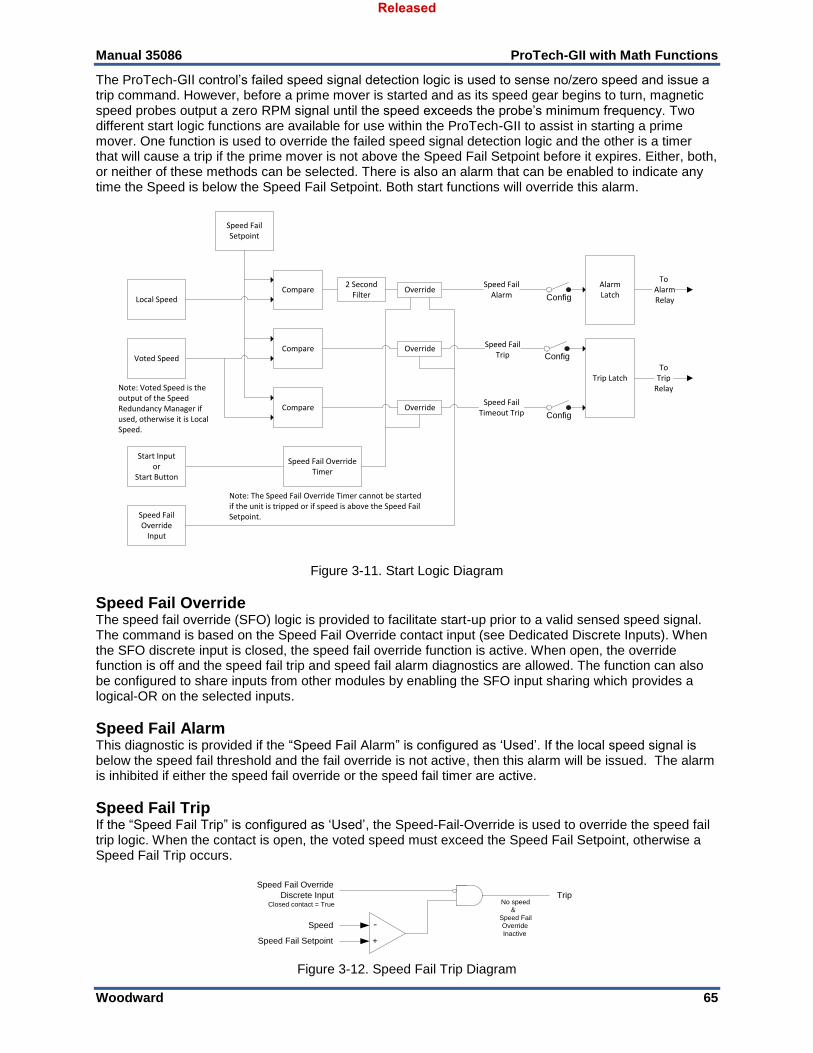
Manual 35086 ProTech-GII with Math Functions
Woodward 65
The ProTech-GII control’s failed speed signal detection logic is used to sense no/zero speed and issue a trip command. However, before a prime mover is started and as its speed gear begins to turn, magnetic speed probes output a zero RPM signal until the speed exceeds the probe’s minimum frequency. Two different start logic functions are available for use within the ProTech-GII to assist in starting a prime mover. One function is used to override the failed speed signal detection logic and the other is a timer that will cause a trip if the prime mover is not above the Speed Fail Setpoint before it expires. Either, both, or neither of these methods can be selected. There is also an alarm that can be enabled to indicate any time the Speed is below the Speed Fail Setpoint. Both start functions will override this alarm.
Compare
AlarmLatch
To Alarm RelayConfig
Trip LatchTo
TripRelay
Config
Config
Compare
Compare
Local Speed
Speed Fail Setpoint
2 Second Filter
Speed FailAlarm
Note: Voted Speed is the output of the Speed Redundancy Manager if used, otherwise it is Local Speed.
Override
Override
Override
Speed FailTrip
Speed FailTimeout Trip
Speed Fail Override
Input
Note: The Speed Fail Override Timer cannot be started if the unit is tripped or if speed is above the Speed Fail Setpoint.
Speed Fail Override Timer
Voted Speed
Start Inputor
Start Button
Figure 3-11. Start Logic Diagram
Speed Fail Override The speed fail override (SFO) logic is provided to facilitate start-up prior to a valid sensed speed signal. The command is based on the Speed Fail Override contact input (see Dedicated Discrete Inputs). When the SFO discrete input is closed, the speed fail override function is active. When open, the override function is off and the speed fail trip and speed fail alarm diagnostics are allowed. The function can also be configured to share inputs from other modules by enabling the SFO input sharing which provides a logical-OR on the selected inputs.
Speed Fail Alarm This diagnostic is provided if the “Speed Fail Alarm” is configured as ‘Used’. If the local speed signal is below the speed fail threshold and the fail override is not active, then this alarm will be issued. The alarm is inhibited if either the speed fail override or the speed fail timer are active.
Speed Fail Trip If the “Speed Fail Trip” is configured as ‘Used’, the Speed-Fail-Override is used to override the speed fail trip logic. When the contact is open, the voted speed must exceed the Speed Fail Setpoint, otherwise a Speed Fail Trip occurs.
Trip
+
-Speed
Speed Fail Setpoint
Speed Fail Override
Discrete InputClosed contact = True No speed
&
Speed Fail
Override
Inactive
Figure 3-12. Speed Fail Trip Diagram
Released
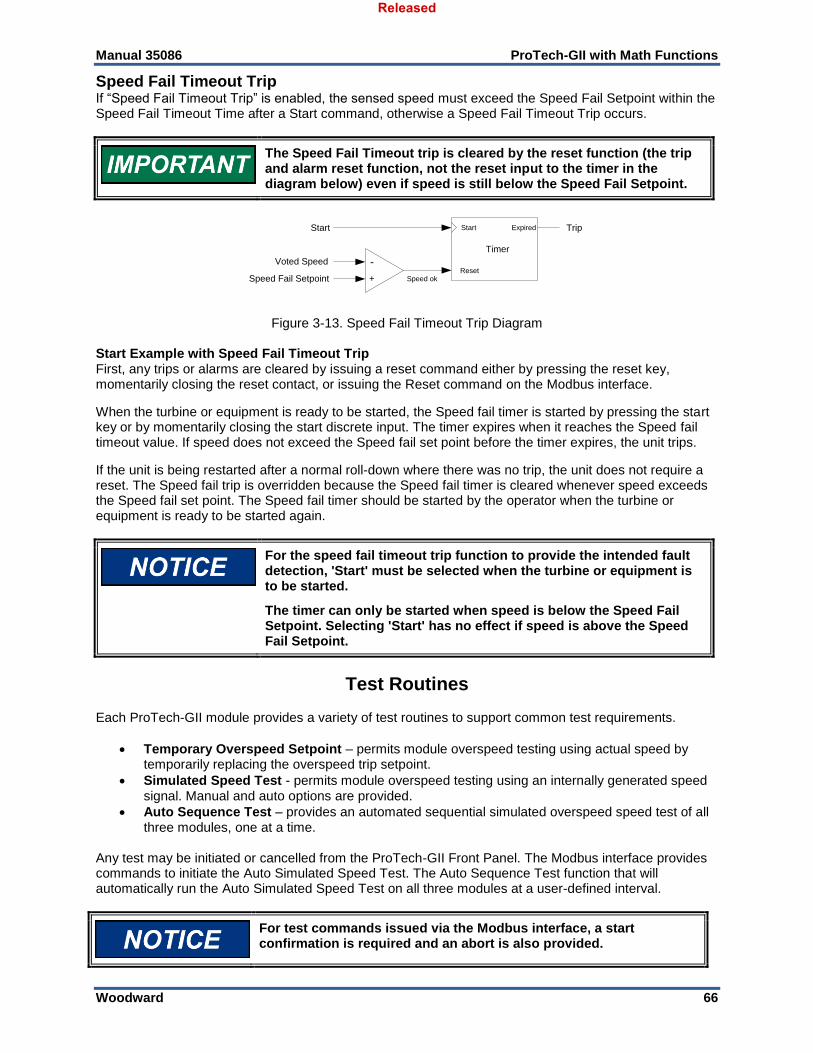
Manual 35086 ProTech-GII with Math Functions
Woodward 66
Speed Fail Timeout Trip If “Speed Fail Timeout Trip” is enabled, the sensed speed must exceed the Speed Fail Setpoint within the Speed Fail Timeout Time after a Start command, otherwise a Speed Fail Timeout Trip occurs.
The Speed Fail Timeout trip is cleared by the reset function (the trip and alarm reset function, not the reset input to the timer in the diagram below) even if speed is still below the Speed Fail Setpoint.
Timer
Reset
StartStart Expired
Speed ok
Trip
+
-Voted Speed
Speed Fail Setpoint
Figure 3-13. Speed Fail Timeout Trip Diagram Start Example with Speed Fail Timeout Trip First, any trips or alarms are cleared by issuing a reset command either by pressing the reset key, momentarily closing the reset contact, or issuing the Reset command on the Modbus interface.
When the turbine or equipment is ready to be started, the Speed fail timer is started by pressing the start key or by momentarily closing the start discrete input. The timer expires when it reaches the Speed fail timeout value. If speed does not exceed the Speed fail set point before the timer expires, the unit trips.
If the unit is being restarted after a normal roll-down where there was no trip, the unit does not require a reset. The Speed fail trip is overridden because the Speed fail timer is cleared whenever speed exceeds the Speed fail set point. The Speed fail timer should be started by the operator when the turbine or equipment is ready to be started again.
For the speed fail timeout trip function to provide the intended fault detection, 'Start' must be selected when the turbine or equipment is to be started.
The timer can only be started when speed is below the Speed Fail Setpoint. Selecting 'Start' has no effect if speed is above the Speed Fail Setpoint.
Test Routines Each ProTech-GII module provides a variety of test routines to support common test requirements.
Temporary Overspeed Setpoint – permits module overspeed testing using actual speed by temporarily replacing the overspeed trip setpoint.
Simulated Speed Test - permits module overspeed testing using an internally generated speed signal. Manual and auto options are provided.
Auto Sequence Test – provides an automated sequential simulated overspeed speed test of all three modules, one at a time.
Any test may be initiated or cancelled from the ProTech-GII Front Panel. The Modbus interface provides commands to initiate the Auto Simulated Speed Test. The Auto Sequence Test function that will automatically run the Auto Simulated Speed Test on all three modules at a user-defined interval.
For test commands issued via the Modbus interface, a start confirmation is required and an abort is also provided.
Released
Manual 35086 ProTech-GII with Math Functions
Woodward 67
There is a configurable test mode permissive that is provided to prevent a test from being started if any module is tripped, in test, or in alarm. This permissive can be configured: Not Tripped—if another module is tripped or in a test; Not In Alarm—if another module is in alarm or in a test; or None—for no permissive. Selecting None means that tests can be run on any module regardless of the condition of the other modules. A test will always be prevented from running if the current module is tripped or in test. Also, tests will be aborted if another module trips or alarms, depending on the test mode permissive setting. One exception to these rules is the Temporary Overspeed Trip Setpoint, which can be applied to multiple modules even if another module is tripped or in alarm. Another exception is the Auto-Sequence Test, which will never be allowed to run if any module is tripped in test or in alarm. Finally, the Lamp Test can be applied to any module at any time without a password. If a test is not permitted or aborted, messages displayed on the front panel explain the cause.
Temporary Overspeed Setpoint This feature temporarily replaces the Overspeed Trip setpoint with a different value for testing. This test mode can be applied to all three modules simultaneously. The Temporary Overspeed Setpoint can be higher or lower than the normal overspeed trip setting.
When the Temporary Overspeed Setpoint is set above the normal overspeed trip, it should not be set above the maximum speed allowed for the unit.
The Temporary Overspeed Setpoint is designed to allow users to test the module’s overspeed function at a level lower than the normal overspeed setting. It also allows users to test the overspeed function of a mechanical bolt or other overspeed protection system that may be at a higher speed than the electronic overspeed trip setting. An alarm is generated when this test is enabled. Also, there is a Temporary Overspeed Trip Timeout feature that prevents an operator from “forgetting” to disable this test. The timeout can be configured from 0 to 30 minutes. When the test is enabled the timer starts, if it reaches the timeout value, the test is automatically aborted. Once the module is in its tripped state, this test is disabled and the module’s overspeed setpoint is returned to its normal setting.
Simulated Speed Tests There are three tests that use an internally generated speed signal to test a module's overspeed trip setpoint and trip output function. The ProTech-GII is defaulted to use the highest level of the Test Mode Permissive so that a module cannot be placed in test while any other unit is tripped, in test, or in alarm. If it is desired to test a unit trip by tripping multiple modules through these simulated speed tests, the Test Mode Permissive can be set to a lower level. Manual Simulated Speed Test This allows the user to manually increase/decrease a modules’ internal frequency generator to perform a test of the overspeed trip function of that module. This test can only be performed from the front panel of the ProTech-GII. When the test is initiated, the frequency generator automatically starts at 100 RPM below the overspeed setpoint. Then the operator can adjust the simulated speed up or down from the front panel of the ProTech-GII. When the overspeed trip occurs, it is logged in the module's trip log and noted as a test. An alarm is generated while this test is enabled. Also, there is a Simulated Speed Timeout feature that prevents an operator from “forgetting” to disable this test. The timeout can be configured from 0 to 30 minutes. When the test is enabled the timer starts, if it reaches the timeout value, the test is automatically aborted. The operator can abort the test at any time.
Released

Manual 35086 ProTech-GII with Math Functions
Woodward 68
Auto Simulated Speed Test This test allows users to easily test the module’s overspeed trip function by having the module’s internal frequency generator automatically ramp up to and above the module’s overspeed set point. This can be initiated from the front panel or via the Modbus interface. The auto test starts at 100 RPM below setpoint. Then the frequency generator ramps up at approximately 10 RPM/s until the overspeed trip occurs. When the overspeed trip occurs, it is logged in the modules’ trip log and noted as a test. If a trip does not occur within 12 seconds from the beginning of the test, the test is aborted and a test failed alarm is generated and logged in the module’s alarm log. To initiate the Auto Simulated Speed Test via a Modbus command, refer to the Modbus Communication Chapter. The test can be aborted either from the front panel or via the Modbus interface. Auto Sequence Test This test is similar to the Auto Simulated Speed Test but allows the ProTech-GII to perform the test automatically on each module on a regular basis. The test can be initiated from the front panel or by a configurable timer. If the configurable timer is used, the test Interval can be configured from 1 to 999 days. When initiated from the front panel, the test interval will be reset. This test will automatically be applied to all three modules. First, the test will be performed on module A, and when the overspeed trip occurs, it is logged in the module's trip log and noted as a test. Then, module A is automatically reset and module B is tested. When the module B test is completed, module C is tested. In this way, periodic testing can be performed automatically on a regular basis with no operator intervention. The operator can disable the Auto Sequence test from the front panel of the module. When the Auto Sequence test is disabled, or if any module is in trip, alarm, or test, the “Time Remaining Until Next Test” will be prevented from counting below one hour. If the timer is already below one hour, it will be increased to 1 hour. When the Auto Sequence Test is enabled again, and no modules are in trip, alarm, or test, this limit on the timer will no longer be in effect. Configuration and initiation of the Auto Sequence Test can only be performed on module A.
Lamp Test Each module provides a lamp test which cycles through all the color options of each front panel LED. When initiated, the test turns all LEDs off, then turns on color option 1 (Tripped=red, Unit Health=red, Alarm=amber), then color option 2 (Tripped=red, Unit Health=green, Alarm=amber), and concludes the test by turning the LEDs off. After the test is completed the LEDs return to displaying the current status.
Note: only the Unit Health LED has a second color option. The Lamp Test can be applied to any module at any time without a password.
Alarm and Trip Latches The ProTech-GII provides pre-defined, self-configured alarm and trip latches based on the configuration of the device’s functions.
Reset Function The Reset Function is associated with both the alarm and trip latches. A Reset can be generated by pressing the reset key on the front panel, from the pre-defined reset contact input, or via the Modbus interface. The reset function can also be configured to share inputs from other modules by enabling the reset input sharing which provides a logical-OR on the selected inputs. This is useful if only one or two discrete contacts are available from a specific circuit or application. The shared reset function is automatically internally connected to numerous functions including the alarm latch, trip latch, and redundancy managers.
Released

Manual 35086 ProTech-GII with Math Functions
Woodward 69
Alarm Latch An "alarm" refers to an action of the ProTech-GII module to bring some condition to the attention to the user. When any of the Alarm Latch inputs becomes true, the output of the alarm latch is set TRUE and the yellow ALARM light is illuminated on the front panel. The Alarm Latch output is connected to the Alarm Relay. Each Alarm Input is individually latched, and those latched outputs are available on the Modbus interface. The individual latches can be reset by the trip reset function if the input is false. The alarm latch output remains TRUE until the reset function occurs and all inputs are false. Here is the complete list of possible Alarm Latch inputs:
Internal Fault Alarm
Configuration Mismatch (if configured)
Power Supply 1 Fault (if configured)
Power Supply 2 Fault (if configured)
Speed Fail Alarm (if configured and speed input is used)
Speed Lost Alarm (if configured and speed input is used)
MPU Open Wire Alarm (if speed redundancy manager is used and speed input is Passive)
Speed Redundancy Manager Input Difference Alarm (if speed redundancy manager is used)
Speed Redundancy Manager Input 1 Invalid (if speed redundancy manager input 1 is used)
Speed Redundancy Manager Input 2 Invalid (if speed redundancy manager input 2 is used)
Speed Redundancy Manager Input 3 Invalid (if speed redundancy manager input 3 is used)
Temporary Overspeed Setpoint Active Alarm
Manual Simulate Speed Test Active Alarm
Auto Simulated Speed Test Active Alarm
Auto Simulated Speed Test Failed Alarm
Auto-Sequence Test Active Alarm
TRIP (if configured)
Trip Latch In almost every case, the ProTech-GII and associated trip system will be designed such that two modules must be issuing a trip command before the unit will be tripped. This is referred to as a 2-out-of-3 (2oo3) trip scheme. In the “Independent Trip Relay” version of the ProTech-GII, the trip action of each module may put part of the trip system into a tripped state and at least two modules must be tripped to trip the unit. In the “Voted Trip Relay” version of the ProTech-GII, at least two modules would have to be in the tripped state for the voter relay to go to its tripped state. A "trip" of the module refers to the action of the ProTech-GII module changing the state of its Trip output. By default, when any of the Trip Latch inputs becomes true, the output of the trip latch is set TRUE. The red TRIPPED light is illuminated on the front panel. The module trip relays are put in the trip state (which could be configured as energized or de-energized). Each Trip Input is individually latched, and those latched outputs are available on the Modbus interface. The individual latches are reset by the reset function if the input is false. The first input to set the Trip latch, or First Out (FO), is also latched. This first out indication is available in the trip log and on the Modbus interface. The Trip latch output remains TRUE and the First Out indication remains unchanged until the reset function occurs and all inputs are false. Optionally the trip latch mode can be configured as non-latching. With this option the inputs are not latched and a reset is not required. Certain failures will still require a reset to clear the (alarm) conditions causing the trip. Example: 2+ invalid speed signals resulting in a Speed Redundancy Manager Trip.
When configured as de-energize-to-trip, the modules power up in the tripped state. When configured as energize-to-trip, the modules power up such that they do not enter the tripped state unless a trip condition is present.
The user can reset a trip by pressing the RESET button on the unit's front panel, or by activating the discrete input that is dedicated to the reset function.
Released
Manual 35086 ProTech-GII with Math Functions
Woodward 70
Here is the complete list of possible trips:
Internal Fault Trip
Power Up Trip (if configured for de-energize to trip)
Configuration Trip
Parameter Error Trip
Overspeed Trip (if speed redundancy manager is used or speed input is used)
Over-Acceleration Trip (if configured and speed redundancy manager is used or speed input is used)
Speed Redundancy Manager Trip (if speed redundancy manager is used)
Speed Probe Open Wire Trip (if speed redundancy manager is not used and the speed input is Passive)
Speed Lost Trip (if configured and the speed input is used)
Speed Fail Trip (if configured and the speed input or speed redundancy manager is used)
Speed Fail Timeout Trip (if configured and the speed input or speed redundancy manager is used)
System Logs Each module in the ProTech-GII logs (saves to non-volatile memory) all trips, alarms, overspeed, and over-acceleration events, and the time and date the event occurred. Peak speed and peak acceleration are also logged with the time and date of the last peak. The logs can be viewed from the front panel of the ProTech-GII or from the PCT tool. With the PCT tool, the Configuration Error Log can also be viewed. Also, the logs can be exported using the PCT tool. The Configuration Error Log is stored in volatile memory, so a power loss will clear this information. All other logs are stored in non-volatile memory so a power loss to the ProTech-GII will not affect this information. The log functions use scrolling buffers that keep the most recent data. The individual log sizes are described in the descriptions below. Logs can be cleared from the front panel with the appropriate password. The Test Level Password is needed to Reset All Logs except the Peak Speed/Acceleration Log. The Config Level Password is required to Reset the Peak Speed/Acceleration Log.
Overspeed/Acceleration Log Each module logs the time and date of the last 20 overspeed or over-acceleration events, the speed and acceleration levels sensed upon issuing a system trip command, and the related maximum speed and acceleration values detected during the trip condition. This includes values generated by internal simulation testing. If the trip occurred during testing, this will also be indicated in the log.
Trip Log Each module logs the last 50 trip events sensed. This log stores the trip description, time and date of the event, “first out” trip indication, and indication if the module was performing a test when the trip occurred. Pressing the TRIPPED VIEW button on the ProTech-GII’s front panel will display the Trip Log screen. This screen displays the most recent TRIP event at the top of the list, and allows users to scroll through all logged events.
Alarm Log Each module logs the last 50 alarms sensed. This log stores the alarm description, time and date of the event, and indication if the module was performing a test when the trip occurred. Pressing the ALARM VIEW button on the ProTech-GII’s front panel will display the Alarm Log screen. This screen displays the most recent ALARM event at the top of the list, and allows users to scroll through all logged events.
Peak Speed/Acceleration Log This log stores the maximum speed and acceleration levels, and associated time of the latest maximum since the last time the log was reset/cleared. This includes the speed and acceleration levels sensed during an automatic or manual overspeed testing routine. This log can be reset from the front panel with the use of the Config Level Password.
Released
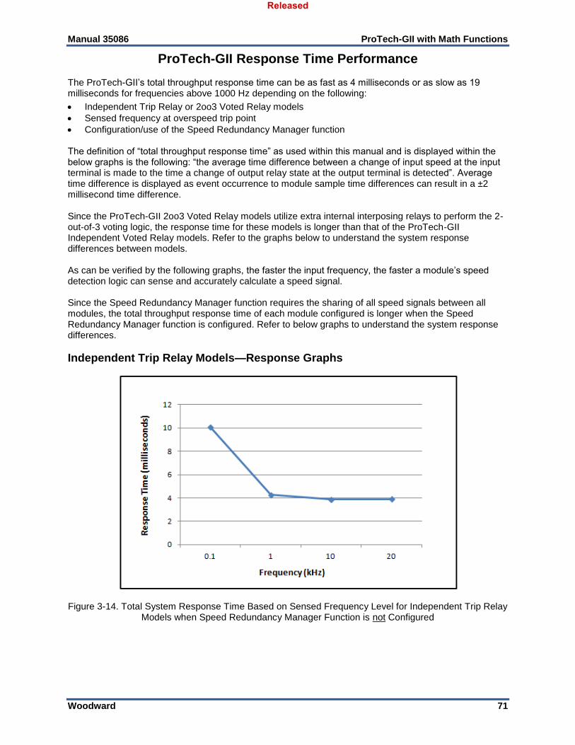
Manual 35086 ProTech-GII with Math Functions
Woodward 71
ProTech-GII Response Time Performance The ProTech-GII’s total throughput response time can be as fast as 4 milliseconds or as slow as 19 milliseconds for frequencies above 1000 Hz depending on the following:
Independent Trip Relay or 2oo3 Voted Relay models
Sensed frequency at overspeed trip point
Configuration/use of the Speed Redundancy Manager function The definition of “total throughput response time” as used within this manual and is displayed within the below graphs is the following: “the average time difference between a change of input speed at the input terminal is made to the time a change of output relay state at the output terminal is detected”. Average time difference is displayed as event occurrence to module sample time differences can result in a ±2 millisecond time difference. Since the ProTech-GII 2oo3 Voted Relay models utilize extra internal interposing relays to perform the 2-out-of-3 voting logic, the response time for these models is longer than that of the ProTech-GII Independent Voted Relay models. Refer to the graphs below to understand the system response differences between models. As can be verified by the following graphs, the faster the input frequency, the faster a module’s speed detection logic can sense and accurately calculate a speed signal. Since the Speed Redundancy Manager function requires the sharing of all speed signals between all modules, the total throughput response time of each module configured is longer when the Speed Redundancy Manager function is configured. Refer to below graphs to understand the system response differences.
Independent Trip Relay Models—Response Graphs
Figure 3-14. Total System Response Time Based on Sensed Frequency Level for Independent Trip Relay
Models when Speed Redundancy Manager Function is not Configured
Released
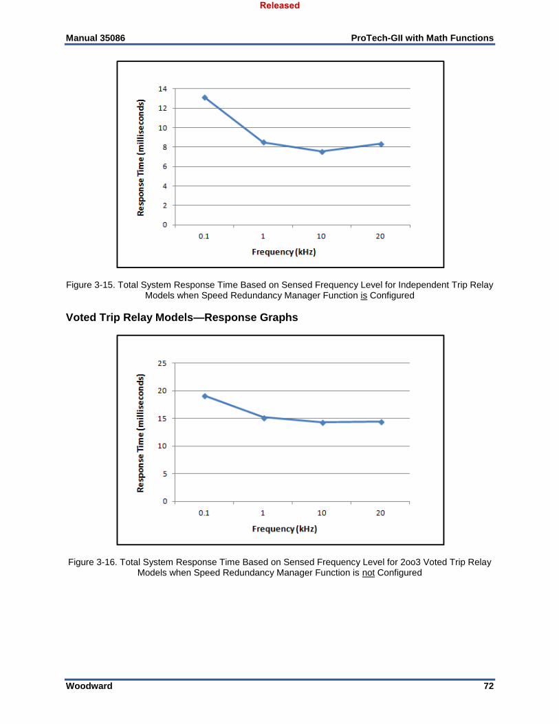
Manual 35086 ProTech-GII with Math Functions
Woodward 72
Figure 3-15. Total System Response Time Based on Sensed Frequency Level for Independent Trip Relay
Models when Speed Redundancy Manager Function is Configured
Voted Trip Relay Models—Response Graphs
Figure 3-16. Total System Response Time Based on Sensed Frequency Level for 2oo3 Voted Trip Relay
Models when Speed Redundancy Manager Function is not Configured
Released
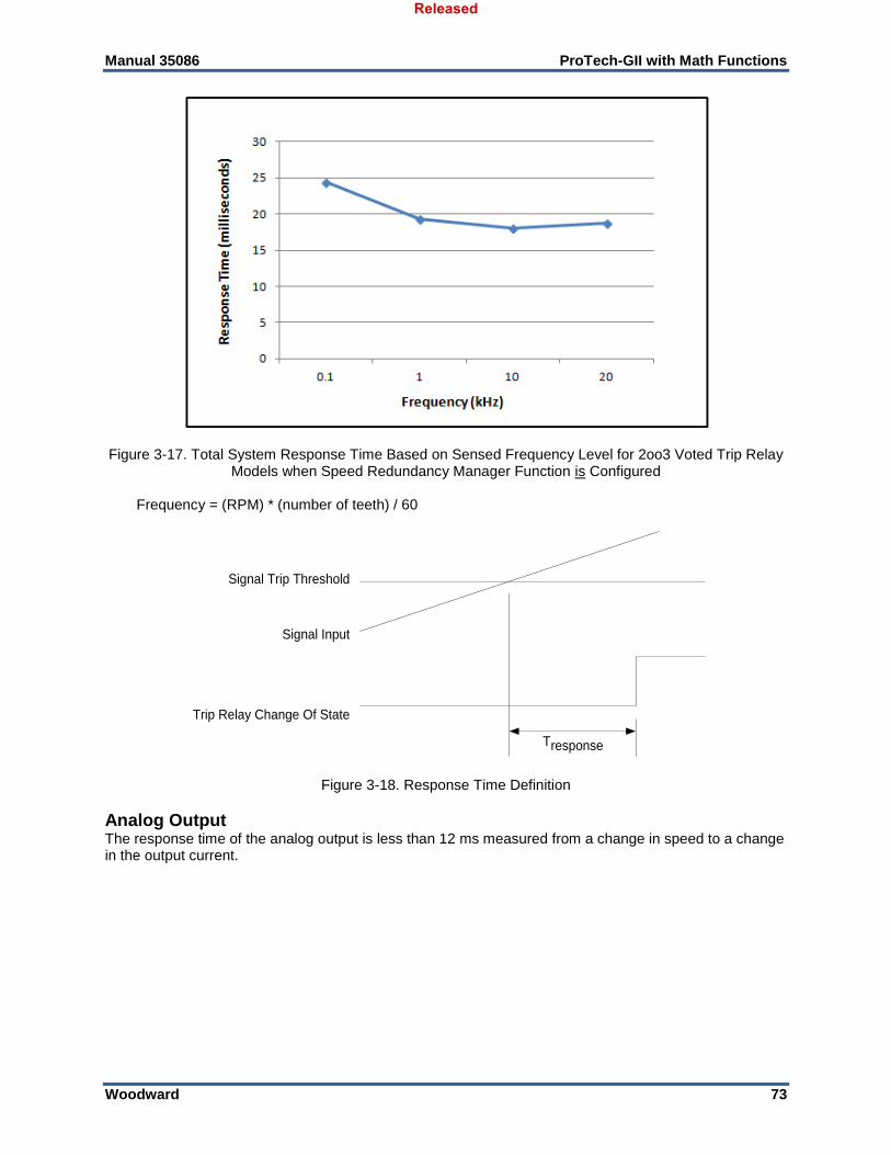
Manual 35086 ProTech-GII with Math Functions
Woodward 73
Figure 3-17. Total System Response Time Based on Sensed Frequency Level for 2oo3 Voted Trip Relay
Models when Speed Redundancy Manager Function is Configured Frequency = (RPM) * (number of teeth) / 60
Signal Trip Threshold
Signal Input
Trip Relay Change Of State
responseT
Figure 3-18. Response Time Definition
Analog Output The response time of the analog output is less than 12 ms measured from a change in speed to a change in the output current.
Released
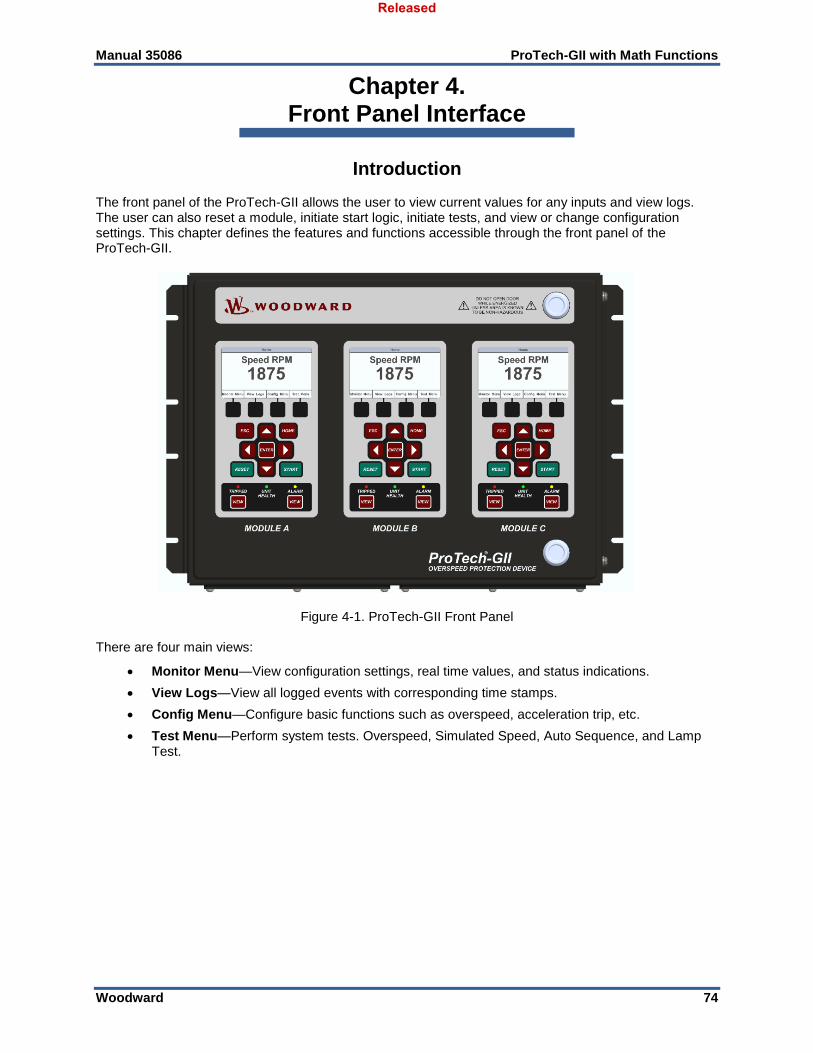
Manual 35086 ProTech-GII with Math Functions
Woodward 74
Chapter 4. Front Panel Interface
Introduction The front panel of the ProTech-GII allows the user to view current values for any inputs and view logs. The user can also reset a module, initiate start logic, initiate tests, and view or change configuration settings. This chapter defines the features and functions accessible through the front panel of the ProTech-GII.
Figure 4-1. ProTech-GII Front Panel There are four main views:
Monitor Menu—View configuration settings, real time values, and status indications.
View Logs—View all logged events with corresponding time stamps.
Config Menu—Configure basic functions such as overspeed, acceleration trip, etc.
Test Menu—Perform system tests. Overspeed, Simulated Speed, Auto Sequence, and Lamp Test.
Released

Manual 35086 ProTech-GII with Math Functions
Woodward 75
Screen Layout Each screen on the ProTech-GII modules follows a consistent layout pattern as shown in Figure 4-2.
Screen Name
Soft Key 1 Soft Key 2 Soft Key 3 Soft Key 4
SCREEN ANNUNCIATION or Screen Message
SCREEN DATA
Figure 4-2. ProTech-GII Screen Screen Name - At the top of each screen is the “Screen Name” which identifies the type of data being displayed or the function being performed on that screen. Screen Data - The middle or main body of each screen shows either data, a menu of selectable fields, or fields for entering data or passwords. Values in BLUE font are values that change in real time. BLACK font is used for static labels or values that can change only when in configuration mode.
Note: In cases where there is too much information to show in the screen data field, an informational bar will appear in the Annunciation/Message area to show the current page number and the total page count, indicating that additional information can be accessed by using the “Up Arrow” and “Down Arrow” keys.
Screen Annunciation or Message - Below the Screen Data, there is an area reserved for Messages to aid the user. If the screen is in one of the Monitor Menu screens and is just displaying data, this space is reserved to annunciate any alarm or trip messages. The alarm or trip messages are shown in a larger text and highlighted with either yellow or red, respectively. Otherwise this field is used to show user prompts to help with selection or entry of data. Soft Keys - At the bottom of each screen, there are up to four (4) Soft Keys descriptions which are each associated with the physical key positioned immediately below the description. Depending on the screen, the soft keys may be used to select different views, enter data such as setpoints or passwords, select from a list of options, or initiate a function such as performing a test or copying a module’s configuration.
Released
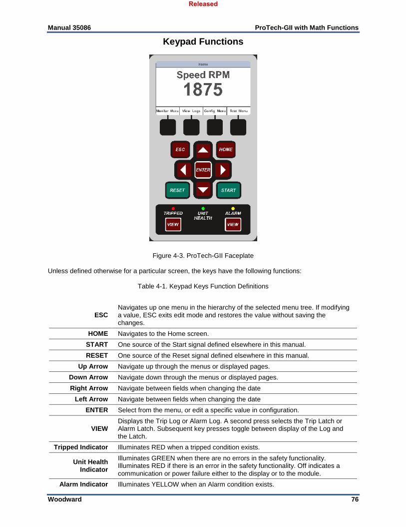
Manual 35086 ProTech-GII with Math Functions
Woodward 76
Keypad Functions
Figure 4-3. ProTech-GII Faceplate Unless defined otherwise for a particular screen, the keys have the following functions:
Table 4-1. Keypad Keys Function Definitions
ESC Navigates up one menu in the hierarchy of the selected menu tree. If modifying a value, ESC exits edit mode and restores the value without saving the changes.
HOME Navigates to the Home screen.
START One source of the Start signal defined elsewhere in this manual.
RESET One source of the Reset signal defined elsewhere in this manual.
Up Arrow Navigate up through the menus or displayed pages.
Down Arrow Navigate down through the menus or displayed pages.
Right Arrow Navigate between fields when changing the date
Left Arrow Navigate between fields when changing the date
ENTER Select from the menu, or edit a specific value in configuration.
VIEW Displays the Trip Log or Alarm Log. A second press selects the Trip Latch or Alarm Latch. Subsequent key presses toggle between display of the Log and the Latch.
Tripped Indicator Illuminates RED when a tripped condition exists.
Unit Health Indicator
Illuminates GREEN when there are no errors in the safety functionality. Illuminates RED if there is an error in the safety functionality. Off indicates a communication or power failure either to the display or to the module.
Alarm Indicator Illuminates YELLOW when an Alarm condition exists.
Released
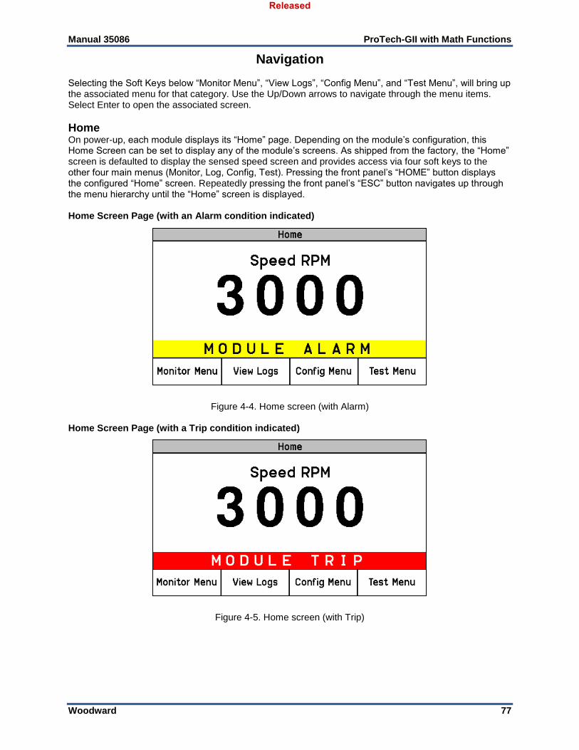
Manual 35086 ProTech-GII with Math Functions
Woodward 77
Navigation Selecting the Soft Keys below “Monitor Menu”, “View Logs”, “Config Menu”, and “Test Menu”, will bring up the associated menu for that category. Use the Up/Down arrows to navigate through the menu items. Select Enter to open the associated screen.
Home On power-up, each module displays its “Home” page. Depending on the module’s configuration, this Home Screen can be set to display any of the module’s screens. As shipped from the factory, the “Home” screen is defaulted to display the sensed speed screen and provides access via four soft keys to the other four main menus (Monitor, Log, Config, Test). Pressing the front panel’s “HOME” button displays the configured “Home” screen. Repeatedly pressing the front panel’s “ESC” button navigates up through the menu hierarchy until the “Home” screen is displayed. Home Screen Page (with an Alarm condition indicated)
Figure 4-4. Home screen (with Alarm) Home Screen Page (with a Trip condition indicated)
Figure 4-5. Home screen (with Trip)
Released
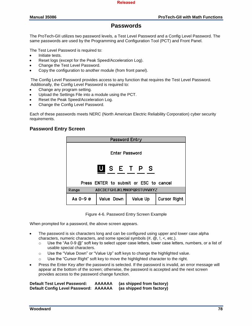
Manual 35086 ProTech-GII with Math Functions
Woodward 78
Passwords The ProTech-GII utilizes two password levels, a Test Level Password and a Config Level Password. The same passwords are used by the Programming and Configuration Tool (PCT) and Front Panel. The Test Level Password is required to:
Initiate tests.
Reset logs (except for the Peak Speed/Acceleration Log).
Change the Test Level Password.
Copy the configuration to another module (from front panel). The Config Level Password provides access to any function that requires the Test Level Password. Additionally, the Config Level Password is required to:
Change any program setting.
Upload the Settings File into a module using the PCT.
Reset the Peak Speed/Acceleration Log.
Change the Config Level Password. Each of these passwords meets NERC (North American Electric Reliability Corporation) cyber security requirements.
Password Entry Screen
Figure 4-6. Password Entry Screen Example When prompted for a password, the above screen appears.
The password is six characters long and can be configured using upper and lower case alpha characters, numeric characters, and some special symbols (#, @, !, <, etc.). o Use the “Aa 0-9 @” soft key to select upper case letters, lower case letters, numbers, or a list of
usable special characters.
o Use the “Value Down” or “Value Up” soft keys to change the highlighted value.
o Use the “Cursor Right” soft key to move the highlighted character to the right.
Press the Enter Key after the password is selected. If the password is invalid, an error message will appear at the bottom of the screen; otherwise, the password is accepted and the next screen provides access to the password change function.
Default Test Level Password: AAAAAA (as shipped from factory) Default Config Level Password: AAAAAA (as shipped from factory)
Released
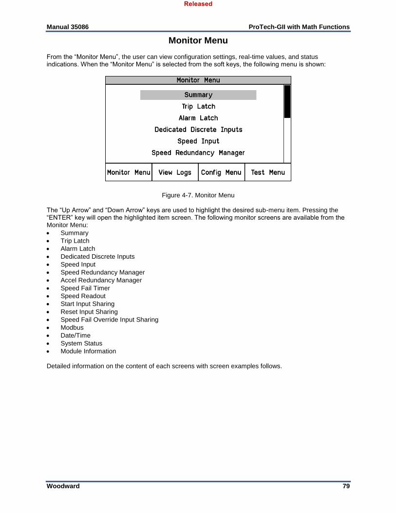
Manual 35086 ProTech-GII with Math Functions
Woodward 79
Monitor Menu From the “Monitor Menu”, the user can view configuration settings, real-time values, and status indications. When the “Monitor Menu” is selected from the soft keys, the following menu is shown:
Figure 4-7. Monitor Menu The “Up Arrow” and “Down Arrow” keys are used to highlight the desired sub-menu item. Pressing the “ENTER” key will open the highlighted item screen. The following monitor screens are available from the Monitor Menu:
Summary
Trip Latch
Alarm Latch
Dedicated Discrete Inputs
Speed Input
Speed Redundancy Manager
Accel Redundancy Manager
Speed Fail Timer
Speed Readout
Start Input Sharing
Reset Input Sharing
Speed Fail Override Input Sharing
Modbus
Date/Time
System Status
Module Information Detailed information on the content of each screens with screen examples follows.
Released
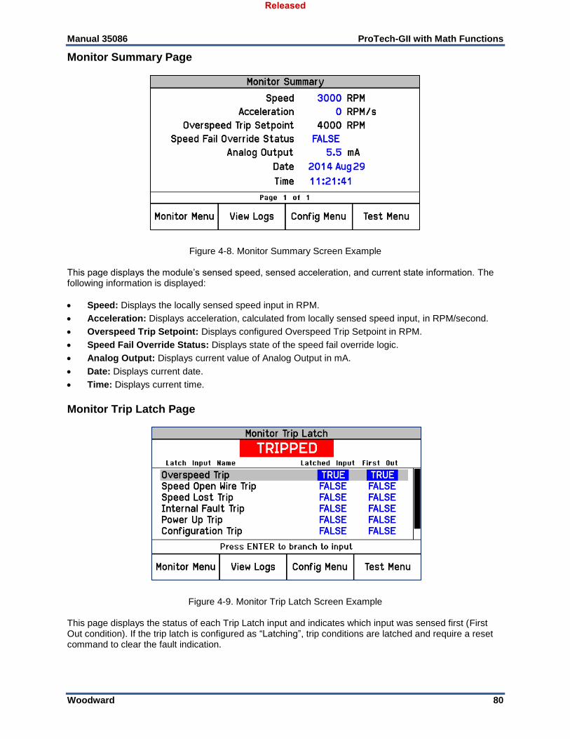
Manual 35086 ProTech-GII with Math Functions
Woodward 80
Monitor Summary Page
Figure 4-8. Monitor Summary Screen Example This page displays the module’s sensed speed, sensed acceleration, and current state information. The following information is displayed:
Speed: Displays the locally sensed speed input in RPM.
Acceleration: Displays acceleration, calculated from locally sensed speed input, in RPM/second.
Overspeed Trip Setpoint: Displays configured Overspeed Trip Setpoint in RPM.
Speed Fail Override Status: Displays state of the speed fail override logic.
Analog Output: Displays current value of Analog Output in mA.
Date: Displays current date.
Time: Displays current time.
Monitor Trip Latch Page
Figure 4-9. Monitor Trip Latch Screen Example This page displays the status of each Trip Latch input and indicates which input was sensed first (First Out condition). If the trip latch is configured as “Latching”, trip conditions are latched and require a reset command to clear the fault indication.
Released
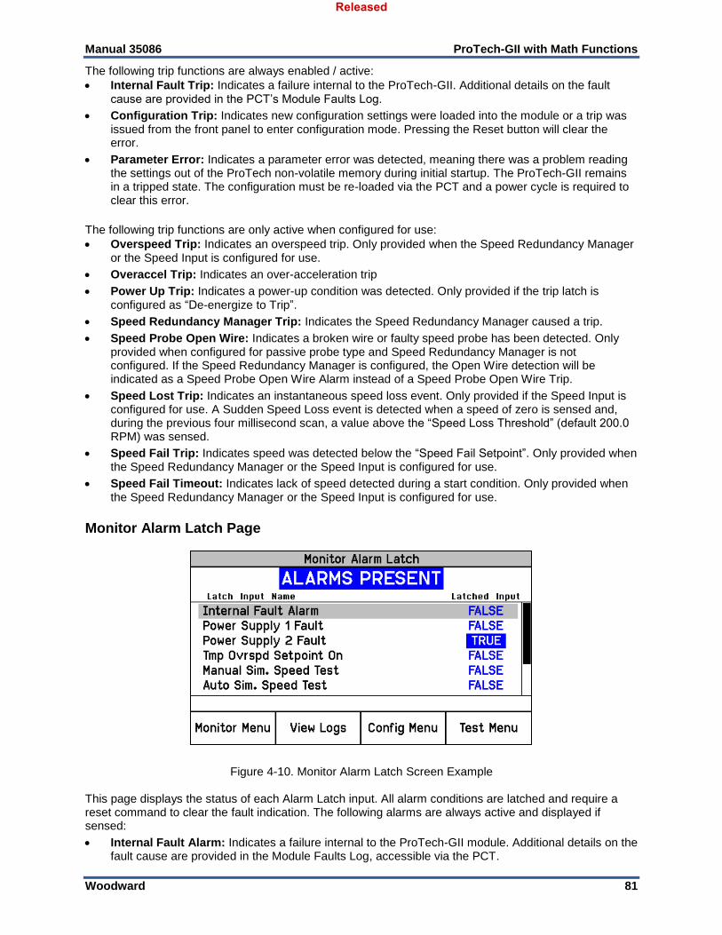
Manual 35086 ProTech-GII with Math Functions
Woodward 81
The following trip functions are always enabled / active:
Internal Fault Trip: Indicates a failure internal to the ProTech-GII. Additional details on the fault cause are provided in the PCT’s Module Faults Log.
Configuration Trip: Indicates new configuration settings were loaded into the module or a trip was issued from the front panel to enter configuration mode. Pressing the Reset button will clear the error.
Parameter Error: Indicates a parameter error was detected, meaning there was a problem reading the settings out of the ProTech non-volatile memory during initial startup. The ProTech-GII remains in a tripped state. The configuration must be re-loaded via the PCT and a power cycle is required to clear this error.
The following trip functions are only active when configured for use:
Overspeed Trip: Indicates an overspeed trip. Only provided when the Speed Redundancy Manager or the Speed Input is configured for use.
Overaccel Trip: Indicates an over-acceleration trip
Power Up Trip: Indicates a power-up condition was detected. Only provided if the trip latch is configured as “De-energize to Trip”.
Speed Redundancy Manager Trip: Indicates the Speed Redundancy Manager caused a trip.
Speed Probe Open Wire: Indicates a broken wire or faulty speed probe has been detected. Only provided when configured for passive probe type and Speed Redundancy Manager is not configured. If the Speed Redundancy Manager is configured, the Open Wire detection will be indicated as a Speed Probe Open Wire Alarm instead of a Speed Probe Open Wire Trip.
Speed Lost Trip: Indicates an instantaneous speed loss event. Only provided if the Speed Input is configured for use. A Sudden Speed Loss event is detected when a speed of zero is sensed and, during the previous four millisecond scan, a value above the “Speed Loss Threshold” (default 200.0 RPM) was sensed.
Speed Fail Trip: Indicates speed was detected below the “Speed Fail Setpoint”. Only provided when the Speed Redundancy Manager or the Speed Input is configured for use.
Speed Fail Timeout: Indicates lack of speed detected during a start condition. Only provided when the Speed Redundancy Manager or the Speed Input is configured for use.
Monitor Alarm Latch Page
Figure 4-10. Monitor Alarm Latch Screen Example This page displays the status of each Alarm Latch input. All alarm conditions are latched and require a reset command to clear the fault indication. The following alarms are always active and displayed if sensed:
Internal Fault Alarm: Indicates a failure internal to the ProTech-GII module. Additional details on the fault cause are provided in the Module Faults Log, accessible via the PCT.
Released
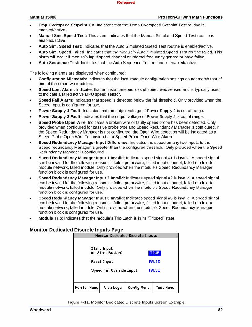
Manual 35086 ProTech-GII with Math Functions
Woodward 82
Tmp Overspeed Setpoint On: Indicates that the Temp Overspeed Setpoint Test routine is enabled/active.
Manual Sim. Speed Test: This alarm indicates that the Manual Simulated Speed Test routine is enabled/active
Auto Sim. Speed Test: Indicates that the Auto Simulated Speed Test routine is enabled/active.
Auto Sim. Speed Failed: Indicates that the module’s Auto Simulated Speed Test routine failed. This alarm will occur if module’s input speed channel or internal frequency generator have failed.
Auto Sequence Test: Indicates that the Auto Sequence Test routine is enabled/active.
The following alarms are displayed when configured:
Configuration Mismatch: Indicates that the local module configuration settings do not match that of one of the other two modules.
Speed Lost Alarm: Indicates that an instantaneous loss of speed was sensed and is typically used to indicate a failed active MPU speed sensor.
Speed Fail Alarm: Indicates that speed is detected below the fail threshold. Only provided when the Speed Input is configured for use.
Power Supply 1 Fault: Indicates that the output voltage of Power Supply 1 is out of range.
Power Supply 2 Fault: Indicates that the output voltage of Power Supply 2 is out of range.
Speed Probe Open Wire: Indicates a broken wire or faulty speed probe has been detected. Only provided when configured for passive probe type and Speed Redundancy Manager is configured. If the Speed Redundancy Manager is not configured, the Open Wire detection will be indicated as a Speed Probe Open Wire Trip instead of a Speed Probe Open Wire Alarm.
Speed Redundancy Manager Input Difference: Indicates the speed on any two inputs to the Speed redundancy Manager is greater than the configured threshold. Only provided when the Speed Redundancy Manager is configured.
Speed Redundancy Manager Input 1 Invalid: Indicates speed signal #1 is invalid. A speed signal can be invalid for the following reasons—failed probe/wire, failed input channel, failed module-to-module network, failed module. Only provided when the module’s Speed Redundancy Manager function block is configured for use.
Speed Redundancy Manager Input 2 Invalid: Indicates speed signal #2 is invalid. A speed signal can be invalid for the following reasons—failed probe/wire, failed input channel, failed module-to-module network, failed module. Only provided when the module’s Speed Redundancy Manager function block is configured for use.
Speed Redundancy Manager Input 3 Invalid: Indicates speed signal #3 is invalid. A speed signal can be invalid for the following reasons—failed probe/wire, failed input channel, failed module-to-module network, failed module. Only provided when the module’s Speed Redundancy Manager function block is configured for use.
Module Trip: Indicates that the module’s Trip Latch is in its “Tripped” state.
Monitor Dedicated Discrete Inputs Page
Figure 4-11. Monitor Dedicated Discrete Inputs Screen Example
Released
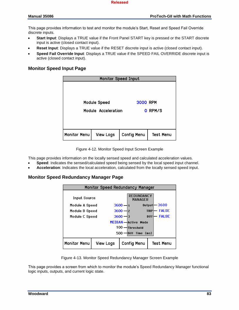
Manual 35086 ProTech-GII with Math Functions
Woodward 83
This page provides information to test and monitor the module’s Start, Reset and Speed Fail Override discrete inputs.
Start Input: Displays a TRUE value if the Front Panel START key is pressed or the START discrete input is active (closed contact input).
Reset Input: Displays a TRUE value if the RESET discrete input is active (closed contact input).
Speed Fail Override Input: Displays a TRUE value if the SPEED FAIL OVERRIDE discrete input is active (closed contact input).
Monitor Speed Input Page
Figure 4-12. Monitor Speed Input Screen Example This page provides information on the locally sensed speed and calculated acceleration values.
Speed: Indicates the sensed/calculated speed being sensed by the local speed input channel.
Acceleration: Indicates the local acceleration, calculated from the locally sensed speed input.
Monitor Speed Redundancy Manager Page
Figure 4-13. Monitor Speed Redundancy Manager Screen Example This page provides a screen from which to monitor the module’s Speed Redundancy Manager functional logic inputs, outputs, and current logic state.
Released
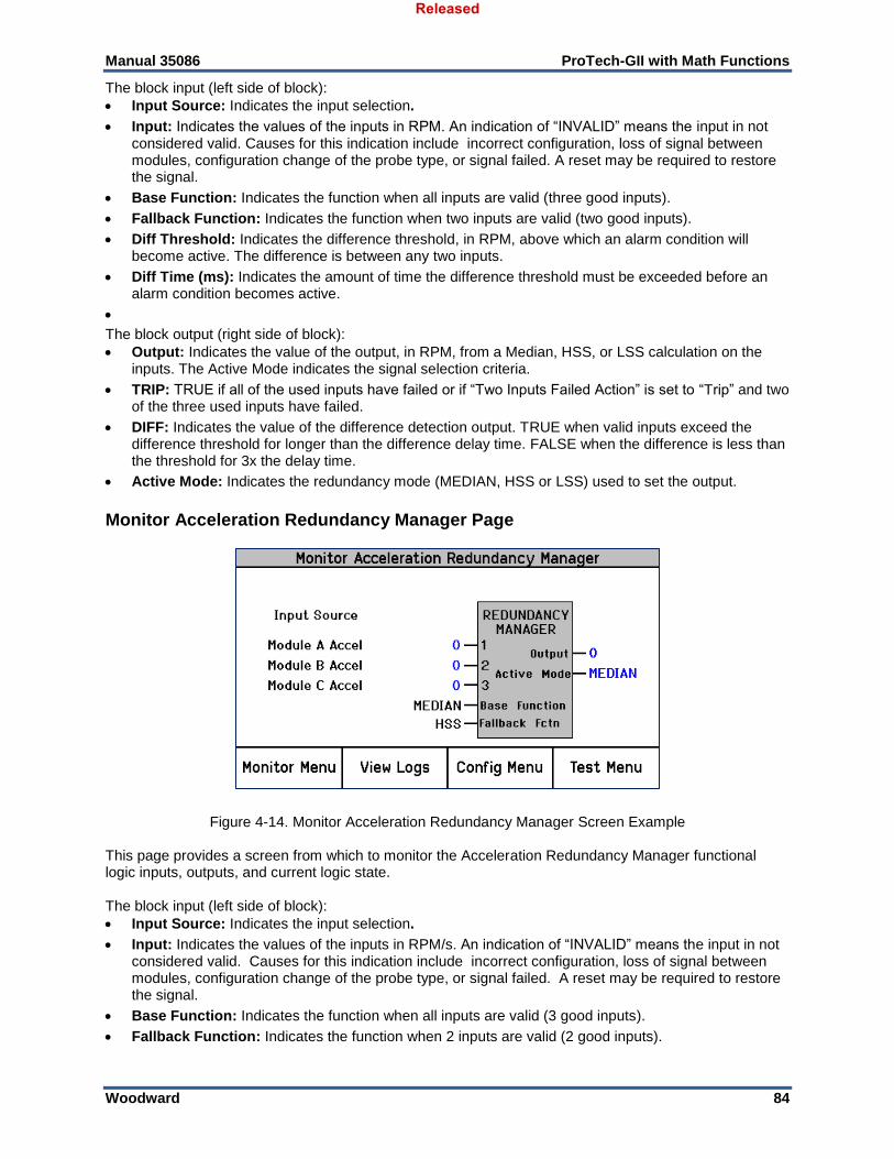
Manual 35086 ProTech-GII with Math Functions
Woodward 84
The block input (left side of block): Input Source: Indicates the input selection.
Input: Indicates the values of the inputs in RPM. An indication of “INVALID” means the input in not considered valid. Causes for this indication include incorrect configuration, loss of signal between modules, configuration change of the probe type, or signal failed. A reset may be required to restore the signal.
Base Function: Indicates the function when all inputs are valid (three good inputs).
Fallback Function: Indicates the function when two inputs are valid (two good inputs).
Diff Threshold: Indicates the difference threshold, in RPM, above which an alarm condition will become active. The difference is between any two inputs.
Diff Time (ms): Indicates the amount of time the difference threshold must be exceeded before an alarm condition becomes active.
The block output (right side of block): Output: Indicates the value of the output, in RPM, from a Median, HSS, or LSS calculation on the
inputs. The Active Mode indicates the signal selection criteria.
TRIP: TRUE if all of the used inputs have failed or if “Two Inputs Failed Action” is set to “Trip” and two of the three used inputs have failed.
DIFF: Indicates the value of the difference detection output. TRUE when valid inputs exceed the difference threshold for longer than the difference delay time. FALSE when the difference is less than the threshold for 3x the delay time.
Active Mode: Indicates the redundancy mode (MEDIAN, HSS or LSS) used to set the output.
Monitor Acceleration Redundancy Manager Page
Figure 4-14. Monitor Acceleration Redundancy Manager Screen Example This page provides a screen from which to monitor the Acceleration Redundancy Manager functional logic inputs, outputs, and current logic state. The block input (left side of block): Input Source: Indicates the input selection.
Input: Indicates the values of the inputs in RPM/s. An indication of “INVALID” means the input in not considered valid. Causes for this indication include incorrect configuration, loss of signal between modules, configuration change of the probe type, or signal failed. A reset may be required to restore the signal.
Base Function: Indicates the function when all inputs are valid (3 good inputs).
Fallback Function: Indicates the function when 2 inputs are valid (2 good inputs).
Released
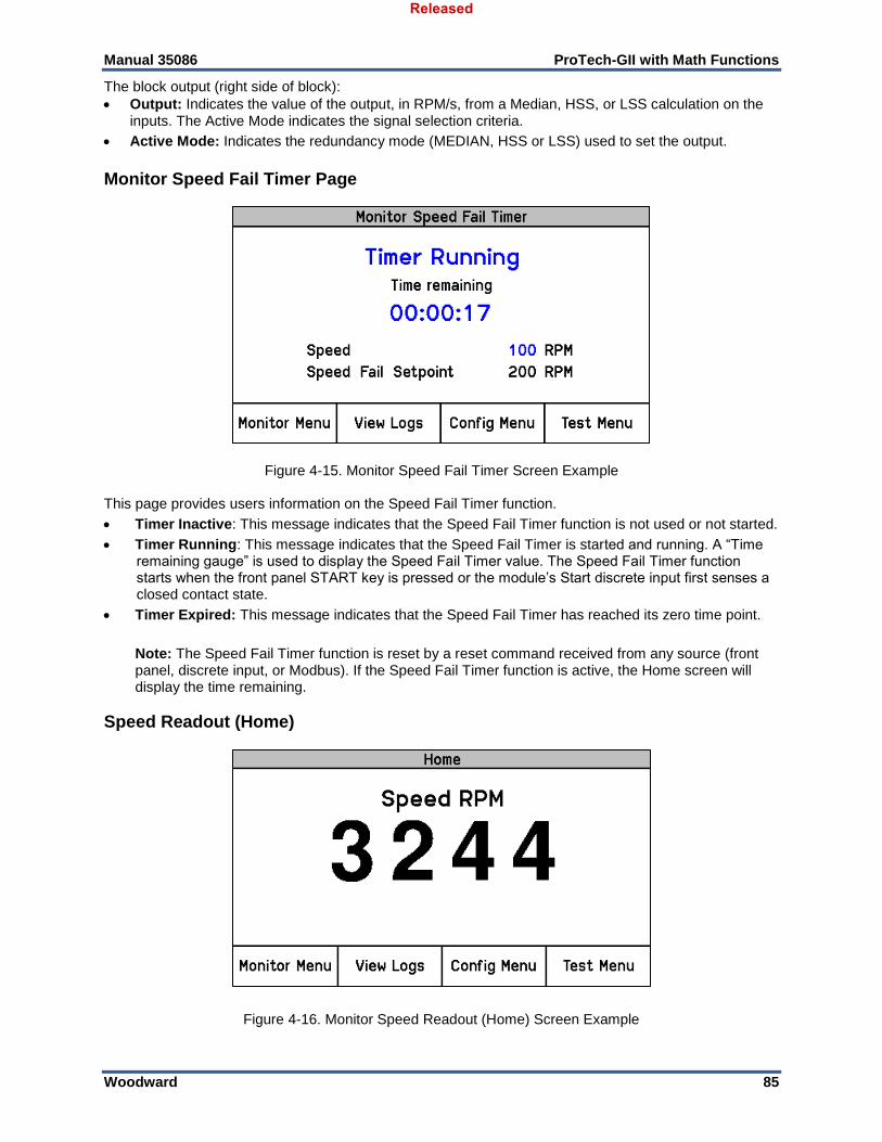
Manual 35086 ProTech-GII with Math Functions
Woodward 85
The block output (right side of block): Output: Indicates the value of the output, in RPM/s, from a Median, HSS, or LSS calculation on the
inputs. The Active Mode indicates the signal selection criteria.
Active Mode: Indicates the redundancy mode (MEDIAN, HSS or LSS) used to set the output.
Monitor Speed Fail Timer Page
Figure 4-15. Monitor Speed Fail Timer Screen Example This page provides users information on the Speed Fail Timer function.
Timer Inactive: This message indicates that the Speed Fail Timer function is not used or not started.
Timer Running: This message indicates that the Speed Fail Timer is started and running. A “Time remaining gauge” is used to display the Speed Fail Timer value. The Speed Fail Timer function starts when the front panel START key is pressed or the module’s Start discrete input first senses a closed contact state.
Timer Expired: This message indicates that the Speed Fail Timer has reached its zero time point.
Note: The Speed Fail Timer function is reset by a reset command received from any source (front panel, discrete input, or Modbus). If the Speed Fail Timer function is active, the Home screen will display the time remaining.
Speed Readout (Home)
Figure 4-16. Monitor Speed Readout (Home) Screen Example
Released
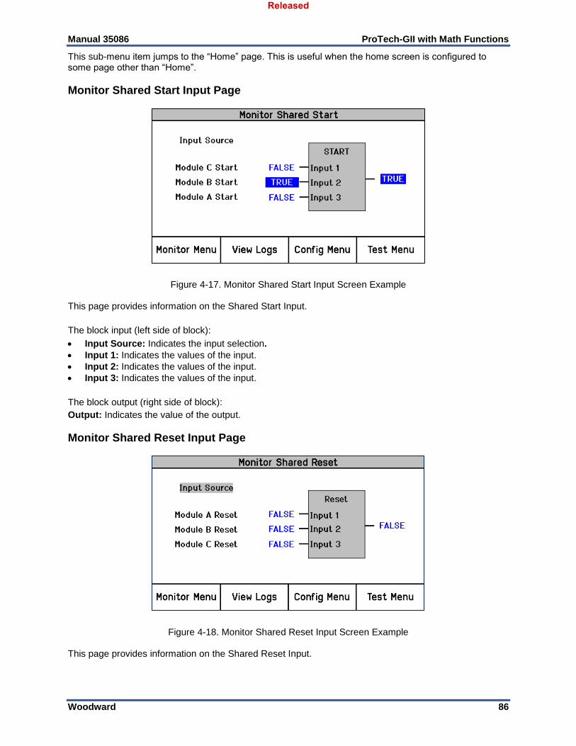
Manual 35086 ProTech-GII with Math Functions
Woodward 86
This sub-menu item jumps to the “Home” page. This is useful when the home screen is configured to some page other than “Home”.
Monitor Shared Start Input Page
Figure 4-17. Monitor Shared Start Input Screen Example This page provides information on the Shared Start Input.
The block input (left side of block):
Input Source: Indicates the input selection.
Input 1: Indicates the values of the input.
Input 2: Indicates the values of the input.
Input 3: Indicates the values of the input.
The block output (right side of block): Output: Indicates the value of the output.
Monitor Shared Reset Input Page
Figure 4-18. Monitor Shared Reset Input Screen Example This page provides information on the Shared Reset Input.
Released
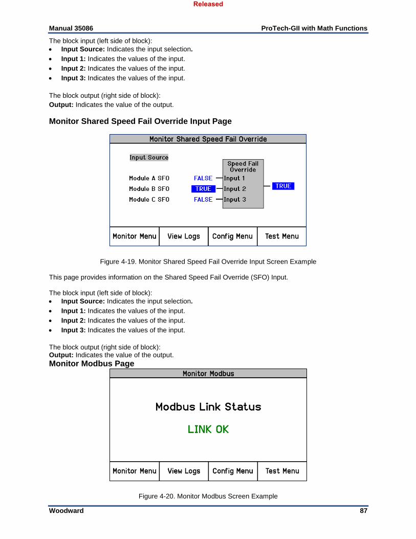
Manual 35086 ProTech-GII with Math Functions
Woodward 87
The block input (left side of block): Input Source: Indicates the input selection.
Input 1: Indicates the values of the input.
Input 2: Indicates the values of the input.
Input 3: Indicates the values of the input.
The block output (right side of block): Output: Indicates the value of the output.
Monitor Shared Speed Fail Override Input Page
Figure 4-19. Monitor Shared Speed Fail Override Input Screen Example This page provides information on the Shared Speed Fail Override (SFO) Input. The block input (left side of block): Input Source: Indicates the input selection.
Input 1: Indicates the values of the input.
Input 2: Indicates the values of the input.
Input 3: Indicates the values of the input.
The block output (right side of block): Output: Indicates the value of the output.
Monitor Modbus Page
Figure 4-20. Monitor Modbus Screen Example
Released
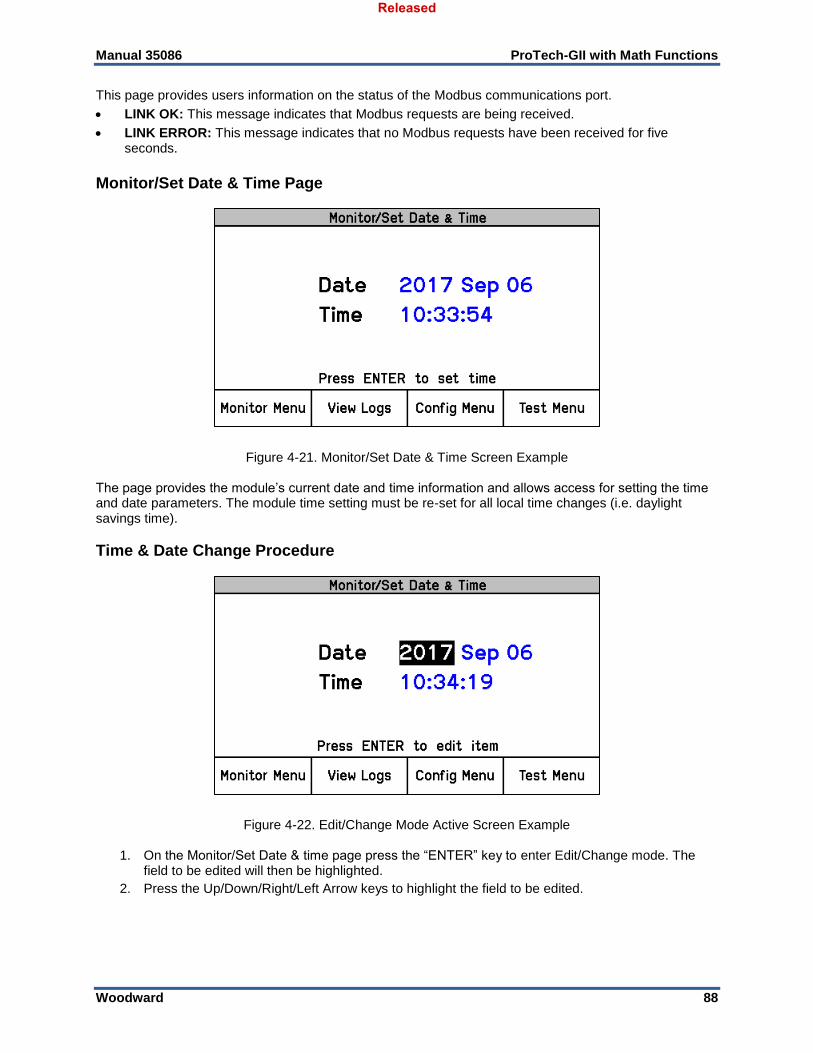
Manual 35086 ProTech-GII with Math Functions
Woodward 88
This page provides users information on the status of the Modbus communications port.
LINK OK: This message indicates that Modbus requests are being received.
LINK ERROR: This message indicates that no Modbus requests have been received for five seconds.
Monitor/Set Date & Time Page
Figure 4-21. Monitor/Set Date & Time Screen Example The page provides the module’s current date and time information and allows access for setting the time and date parameters. The module time setting must be re-set for all local time changes (i.e. daylight savings time).
Time & Date Change Procedure
Figure 4-22. Edit/Change Mode Active Screen Example
1. On the Monitor/Set Date & time page press the “ENTER” key to enter Edit/Change mode. The field to be edited will then be highlighted.
2. Press the Up/Down/Right/Left Arrow keys to highlight the field to be edited.
Released
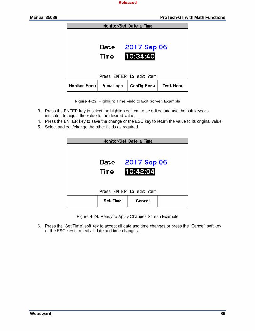
Manual 35086 ProTech-GII with Math Functions
Woodward 89
Figure 4-23. Highlight Time Field to Edit Screen Example
3. Press the ENTER key to select the highlighted item to be edited and use the soft keys as indicated to adjust the value to the desired value.
4. Press the ENTER key to save the change or the ESC key to return the value to its original value.
5. Select and edit/change the other fields as required.
Figure 4-24. Ready to Apply Changes Screen Example
6. Press the “Set Time” soft key to accept all date and time changes or press the “Cancel” soft key or the ESC key to reject all date and time changes.
Released
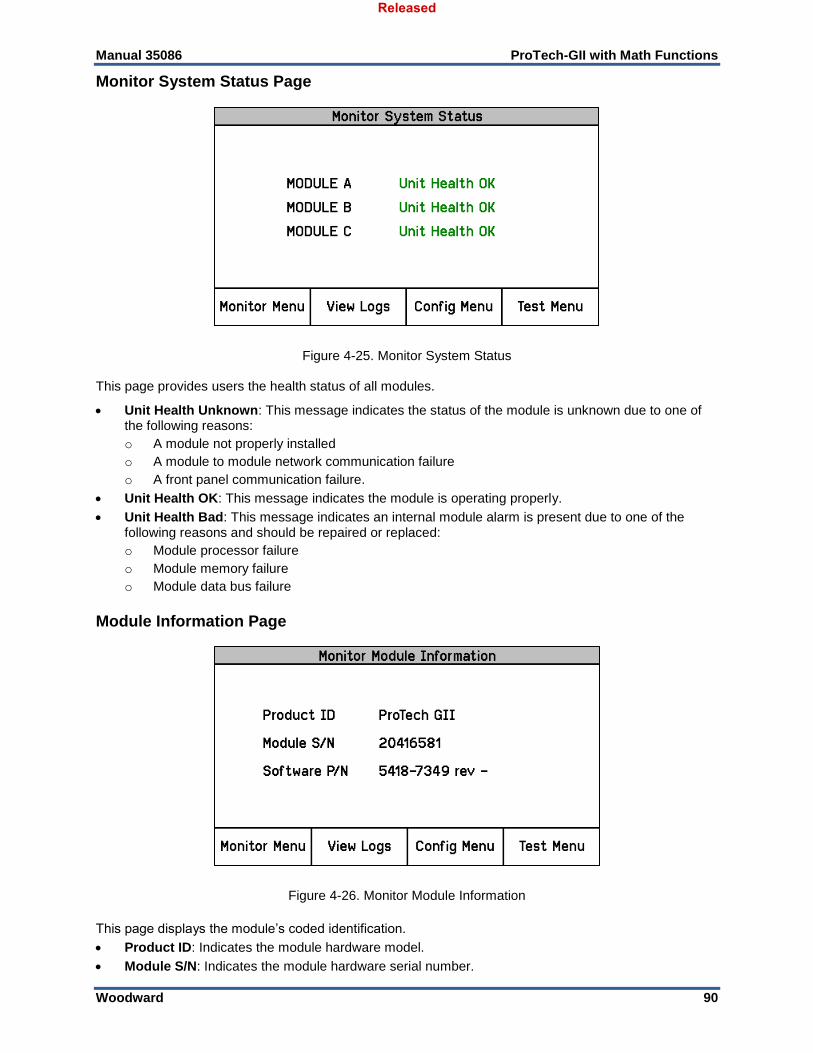
Manual 35086 ProTech-GII with Math Functions
Woodward 90
Monitor System Status Page
Figure 4-25. Monitor System Status This page provides users the health status of all modules.
Unit Health Unknown: This message indicates the status of the module is unknown due to one of the following reasons:
o A module not properly installed
o A module to module network communication failure
o A front panel communication failure.
Unit Health OK: This message indicates the module is operating properly.
Unit Health Bad: This message indicates an internal module alarm is present due to one of the following reasons and should be repaired or replaced:
o Module processor failure
o Module memory failure
o Module data bus failure
Module Information Page
Figure 4-26. Monitor Module Information
This page displays the module’s coded identification.
Product ID: Indicates the module hardware model.
Module S/N: Indicates the module hardware serial number.
Released
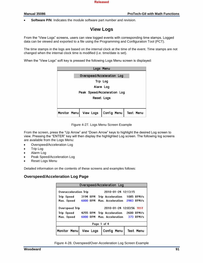
Manual 35086 ProTech-GII with Math Functions
Woodward 91
Software P/N: Indicates the module software part number and revision.
View Logs From the “View Logs” screens, users can view logged events with corresponding time stamps. Logged data can be viewed and exported to a file using the Programming and Configuration Tool (PCT). The time stamps in the logs are based on the internal clock at the time of the event. Time stamps are not changed when the internal clock time is modified (i.e. time/date is set). When the “View Logs” soft key is pressed the following Logs Menu screen is displayed:
Figure 4-27. Logs Menu Screen Example From the screen, press the “Up Arrow” and “Down Arrow” keys to highlight the desired Log screen to view. Pressing the “ENTER” key will then display the highlighted Log screen. The following log screens are available from the Logs Menu:
Overspeed/Acceleration Log
Trip Log
Alarm Log
Peak Speed/Acceleration Log
Reset Logs Menu Detailed information on the contents of these screens and examples follows:
Overspeed/Acceleration Log Page
Figure 4-28. Overspeed/Over-Acceleration Log Screen Example
Released
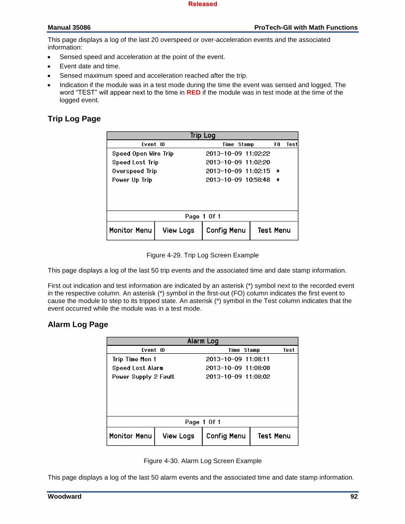
Manual 35086 ProTech-GII with Math Functions
Woodward 92
This page displays a log of the last 20 overspeed or over-acceleration events and the associated information:
Sensed speed and acceleration at the point of the event.
Event date and time.
Sensed maximum speed and acceleration reached after the trip.
Indication if the module was in a test mode during the time the event was sensed and logged. The word “TEST” will appear next to the time in RED if the module was in test mode at the time of the logged event.
Trip Log Page
Figure 4-29. Trip Log Screen Example This page displays a log of the last 50 trip events and the associated time and date stamp information. First out indication and test information are indicated by an asterisk (*) symbol next to the recorded event in the respective column. An asterisk (*) symbol in the first-out (FO) column indicates the first event to cause the module to step to its tripped state. An asterisk (*) symbol in the Test column indicates that the event occurred while the module was in a test mode.
Alarm Log Page
Figure 4-30. Alarm Log Screen Example
This page displays a log of the last 50 alarm events and the associated time and date stamp information.
Released
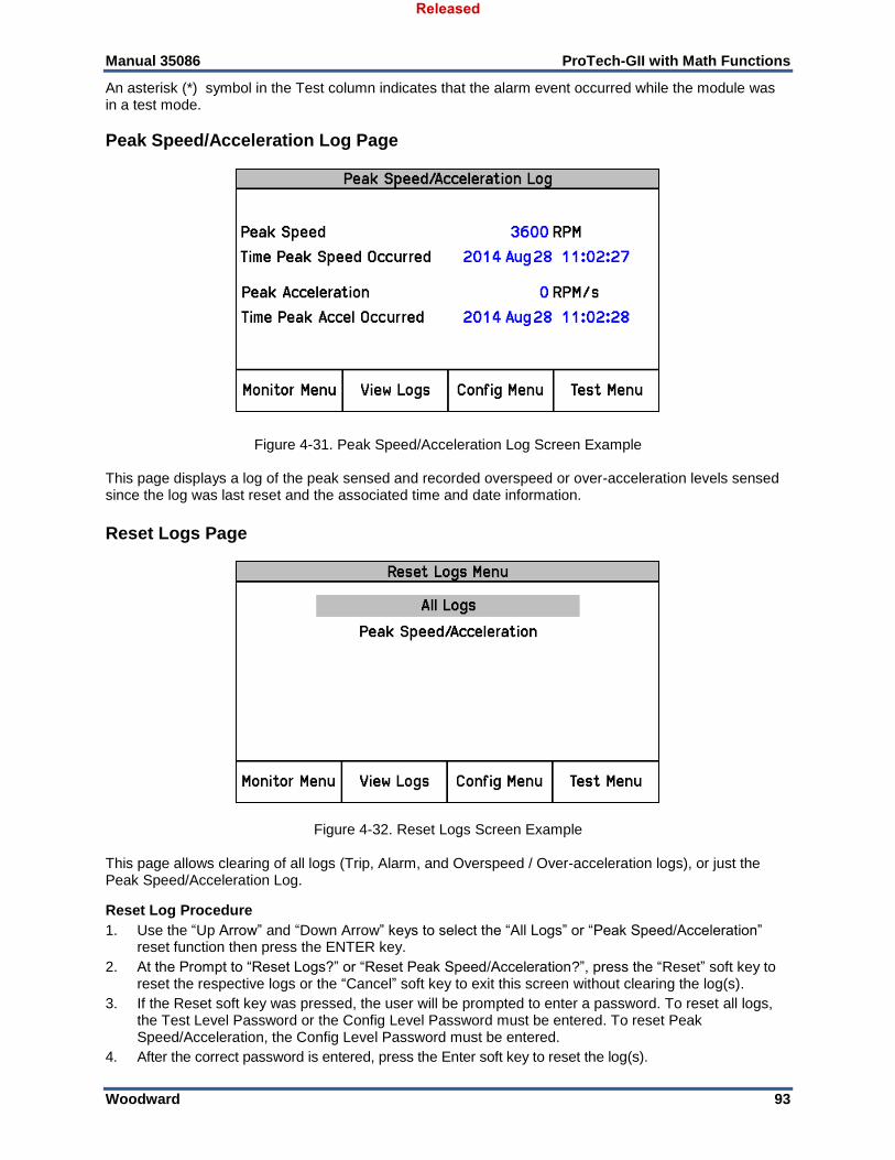
Manual 35086 ProTech-GII with Math Functions
Woodward 93
An asterisk (*) symbol in the Test column indicates that the alarm event occurred while the module was in a test mode.
Peak Speed/Acceleration Log Page
Figure 4-31. Peak Speed/Acceleration Log Screen Example This page displays a log of the peak sensed and recorded overspeed or over-acceleration levels sensed since the log was last reset and the associated time and date information.
Reset Logs Page
Figure 4-32. Reset Logs Screen Example This page allows clearing of all logs (Trip, Alarm, and Overspeed / Over-acceleration logs), or just the Peak Speed/Acceleration Log.
Reset Log Procedure
1. Use the “Up Arrow” and “Down Arrow” keys to select the “All Logs” or “Peak Speed/Acceleration” reset function then press the ENTER key.
2. At the Prompt to “Reset Logs?” or “Reset Peak Speed/Acceleration?”, press the “Reset” soft key to reset the respective logs or the “Cancel” soft key to exit this screen without clearing the log(s).
3. If the Reset soft key was pressed, the user will be prompted to enter a password. To reset all logs, the Test Level Password or the Config Level Password must be entered. To reset Peak Speed/Acceleration, the Config Level Password must be entered.
4. After the correct password is entered, press the Enter soft key to reset the log(s).
Released
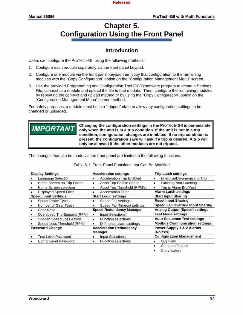
Manual 35086 ProTech-GII with Math Functions
Woodward 94
Chapter 5. Configuration Using the Front Panel
Introduction Users can configure the ProTech-GII using the following methods:
1. Configure each module separately via the front panel keypad.
2. Configure one module via the front panel keypad then copy that configuration to the remaining modules with the “Copy Configuration” option on the “Configuration Management Menu” screen.
3. Use the provided Programming and Configuration Tool (PCT) software program to create a Settings File, connect to a module and upload the file to that module. Then, configure the remaining modules by repeating the connect and upload method or by using the “Copy Configuration” option on the “Configuration Management Menu” screen method.
For safety purposes, a module must be in a “tripped” state to allow any configuration settings to be changed or uploaded.
Changing the configuration settings in the ProTech-GII is permissible only when the unit is in a trip condition. If the unit is not in a trip condition, configuration changes are inhibited. If no trip condition is present, the configuration save will ask if a trip is desired. A trip will only be allowed if the other modules are not tripped.
The changes that can be made via the front panel are limited to the following functions.
Table 5-1. Front Panel Functions that Can Be Modified
Display Settings Acceleration settings Trip Latch settings
Language Selection Acceleration Trip Enabled Energize/De-energize to Trip
Home Screen on Trip Option Accel Trip Enable Speed Latching/Non-Latching
Home Screen selection Accel Trip Threshold [RPM/s] Trip is Alarm [No/Yes]
Displayed Speed Filter Acceleration Filter Alarm Latch settings
Speed Input Settings Start Logic settings Start Input Sharing
Speed Probe Type Speed Fail settings Reset Input Sharing
Number of Gear Teeth Speed Fail Timeout settings Speed Fail Override Input Sharing
Gear Ratio Speed Redundancy Manager Analog Output (Speed) settings
Overspeed Trip Setpoint [RPM] Input Selections Test Mode settings
Sudden Speed Loss Action Function selections Auto-Sequence Test settings
Speed Loss Threshold [RPM] Difference alarm settings Modbus Communication settings
Password Change Acceleration Redundancy Manager
Power Supply 1 & 2 Alarms [No/Yes]
Test Level Password Input Selections Configuration Management
Config Level Password Function selections Overview
Compare feature
Copy feature
Released
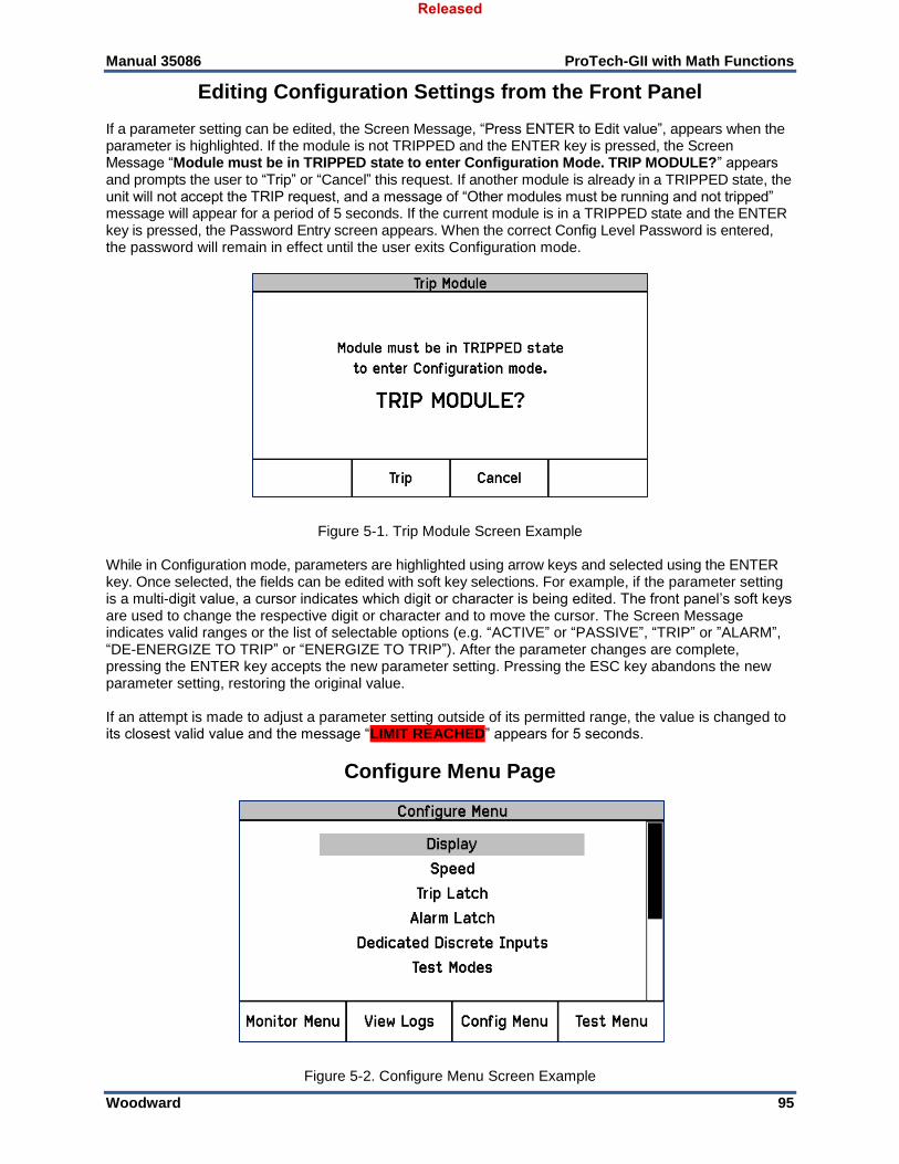
Manual 35086 ProTech-GII with Math Functions
Woodward 95
Editing Configuration Settings from the Front Panel If a parameter setting can be edited, the Screen Message, “Press ENTER to Edit value”, appears when the parameter is highlighted. If the module is not TRIPPED and the ENTER key is pressed, the Screen Message “Module must be in TRIPPED state to enter Configuration Mode. TRIP MODULE?” appears and prompts the user to “Trip” or “Cancel” this request. If another module is already in a TRIPPED state, the unit will not accept the TRIP request, and a message of “Other modules must be running and not tripped” message will appear for a period of 5 seconds. If the current module is in a TRIPPED state and the ENTER key is pressed, the Password Entry screen appears. When the correct Config Level Password is entered, the password will remain in effect until the user exits Configuration mode.
Figure 5-1. Trip Module Screen Example While in Configuration mode, parameters are highlighted using arrow keys and selected using the ENTER key. Once selected, the fields can be edited with soft key selections. For example, if the parameter setting is a multi-digit value, a cursor indicates which digit or character is being edited. The front panel’s soft keys are used to change the respective digit or character and to move the cursor. The Screen Message indicates valid ranges or the list of selectable options (e.g. “ACTIVE” or “PASSIVE”, “TRIP” or ”ALARM”, “DE-ENERGIZE TO TRIP” or “ENERGIZE TO TRIP”). After the parameter changes are complete, pressing the ENTER key accepts the new parameter setting. Pressing the ESC key abandons the new parameter setting, restoring the original value. If an attempt is made to adjust a parameter setting outside of its permitted range, the value is changed to its closest valid value and the message “LIMIT REACHED” appears for 5 seconds.
Configure Menu Page
Figure 5-2. Configure Menu Screen Example
Released

Manual 35086 ProTech-GII with Math Functions
Woodward 96
The “Up Arrow” and “Down Arrow” keys are used to highlight the desired page. The ENTER key selects the page.
Configure Menu Page Descriptions
Display: This page is used to set the language, the display action when a trip occurs, the Home page and the display filter time.
Speed: This page is used to configure the local Speed, Acceleration, Start Logic, Speed Redundancy, and Acceleration Redundancy settings.
Trip Latch: This page is used to configure the local Trip Latch function.
Alarm Latch: This page is used to configure the local Alarm Latch function.
Dedicated Discrete Inputs: This page is used to configure the Reset, Start, and Speed Fail Override input sharing.
Test Modes: This page is used to configure the local Test Routines.
Auto-Sequence Test: This page is used to configure the Auto-Sequence Test Routine. This routine can only be configured from Module A.
Modbus: This page is used to configure the local Modbus communication link.
Power Supply Alarms: This page is used to configure the local power supply alarm logic.
Configuration Management Menu: This page is used to view the configuration CRCs, configure the module-to-module configuration comparison function, and to use the module-to-module configuration copy function.
Password Change Menu: This page is used to set the Test Level Password and Config Level Password.
Configuration Procedure 1. Module must be in a “tripped” state to make any configuration changes.
2. Select the “Config Menu” soft key.
3. Use the Up / Down Arrow keys to select the desired category and press the ENTER key to select.
4. Use the Up / Down Arrow keys to scroll to desired parameter setting then press the ENTER key to select.
5. If the module is not in the “Configuration” mode, the password entry screen will appear. Enter the configuration level password then press the ENTER key. See the password section of this manual for information on entering a password.
6. The screen is now in edit mode. Using the soft keys, edit the desired value:
a. Use the "Cursor Left" key to move to the left.
b. Use the "Value Down" or "Value Up" keys to change the highlighted value.
c. Use the "Cursor Right" key to move to the right.
d. Use "Select Left" or "Select Right" to select a different option.
7. Use the front panel Up / Down Arrow keys and ESC / ENTER keys to navigate within all Config Menu pages to configure desired parameter settings.
8. After all desired parameters have been configured; press the HOME key to exit Configure Mode.
9. If any parameters were changed, the module will display the “Save Configuration” screen (refer to below figure). At this point the user can press the respective soft button to choose the desired action:
a. Save: This action saves any configuration changes, exits Configuration Mode, then displays the Home screen.
b. Discard: This action does not save any configuration changes, exits Configuration Mode, then displays the Home screen.
Released
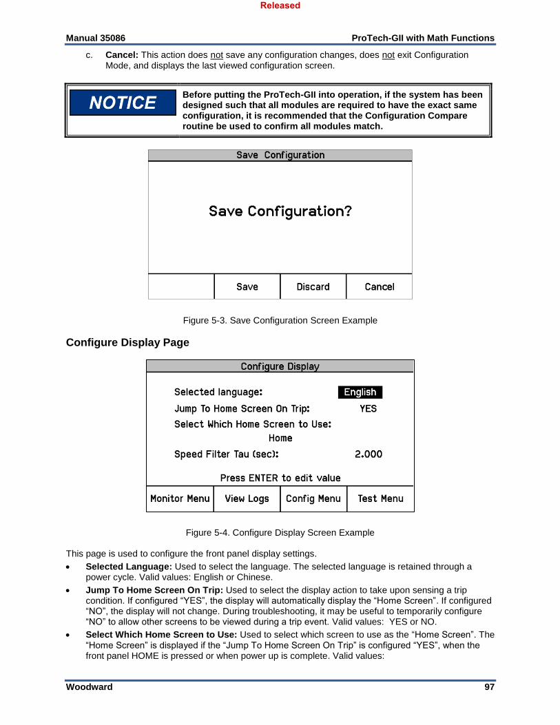
Manual 35086 ProTech-GII with Math Functions
Woodward 97
c. Cancel: This action does not save any configuration changes, does not exit Configuration Mode, and displays the last viewed configuration screen.
Before putting the ProTech-GII into operation, if the system has been designed such that all modules are required to have the exact same configuration, it is recommended that the Configuration Compare routine be used to confirm all modules match.
Figure 5-3. Save Configuration Screen Example
Configure Display Page
Figure 5-4. Configure Display Screen Example This page is used to configure the front panel display settings.
Selected Language: Used to select the language. The selected language is retained through a power cycle. Valid values: English or Chinese.
Jump To Home Screen On Trip: Used to select the display action to take upon sensing a trip condition. If configured “YES”, the display will automatically display the “Home Screen”. If configured “NO”, the display will not change. During troubleshooting, it may be useful to temporarily configure “NO” to allow other screens to be viewed during a trip event. Valid values: YES or NO.
Select Which Home Screen to Use: Used to select which screen to use as the “Home Screen”. The “Home Screen” is displayed if the “Jump To Home Screen On Trip” is configured “YES”, when the front panel HOME is pressed or when power up is complete. Valid values:
Released
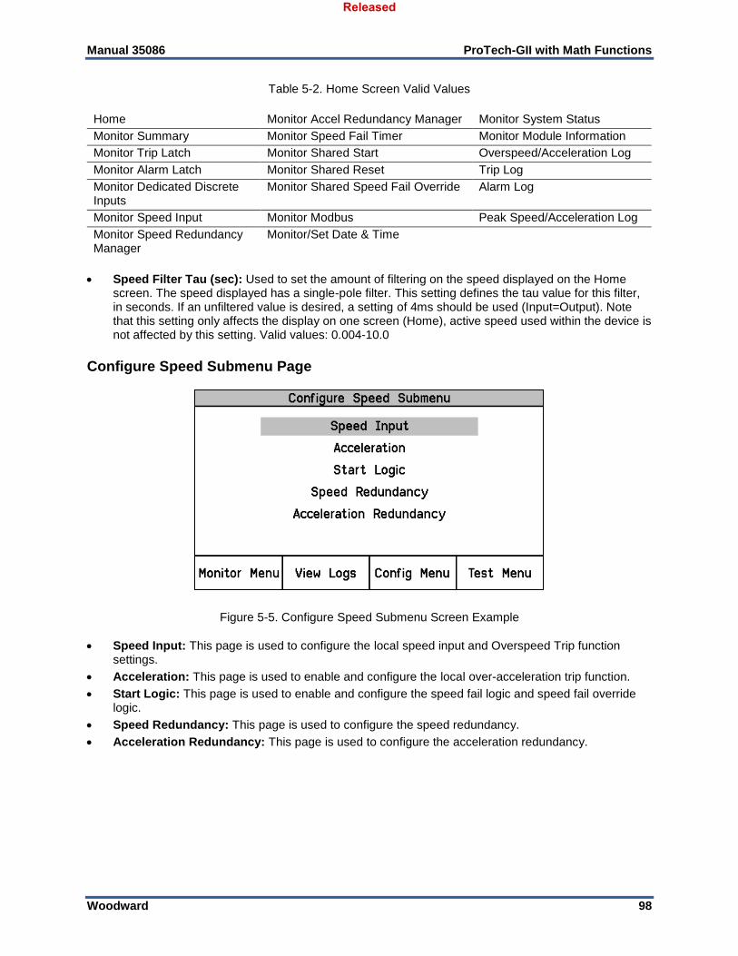
Manual 35086 ProTech-GII with Math Functions
Woodward 98
Table 5-2. Home Screen Valid Values
Home Monitor Accel Redundancy Manager Monitor System Status
Monitor Summary Monitor Speed Fail Timer Monitor Module Information
Monitor Trip Latch Monitor Shared Start Overspeed/Acceleration Log
Monitor Alarm Latch Monitor Shared Reset Trip Log
Monitor Dedicated Discrete Inputs
Monitor Shared Speed Fail Override Alarm Log
Monitor Speed Input Monitor Modbus Peak Speed/Acceleration Log
Monitor Speed Redundancy Manager
Monitor/Set Date & Time
Speed Filter Tau (sec): Used to set the amount of filtering on the speed displayed on the Home screen. The speed displayed has a single-pole filter. This setting defines the tau value for this filter, in seconds. If an unfiltered value is desired, a setting of 4ms should be used (Input=Output). Note that this setting only affects the display on one screen (Home), active speed used within the device is not affected by this setting. Valid values: 0.004-10.0
Configure Speed Submenu Page
Figure 5-5. Configure Speed Submenu Screen Example
Speed Input: This page is used to configure the local speed input and Overspeed Trip function settings.
Acceleration: This page is used to enable and configure the local over-acceleration trip function.
Start Logic: This page is used to enable and configure the speed fail logic and speed fail override logic.
Speed Redundancy: This page is used to configure the speed redundancy.
Acceleration Redundancy: This page is used to configure the acceleration redundancy.
Released
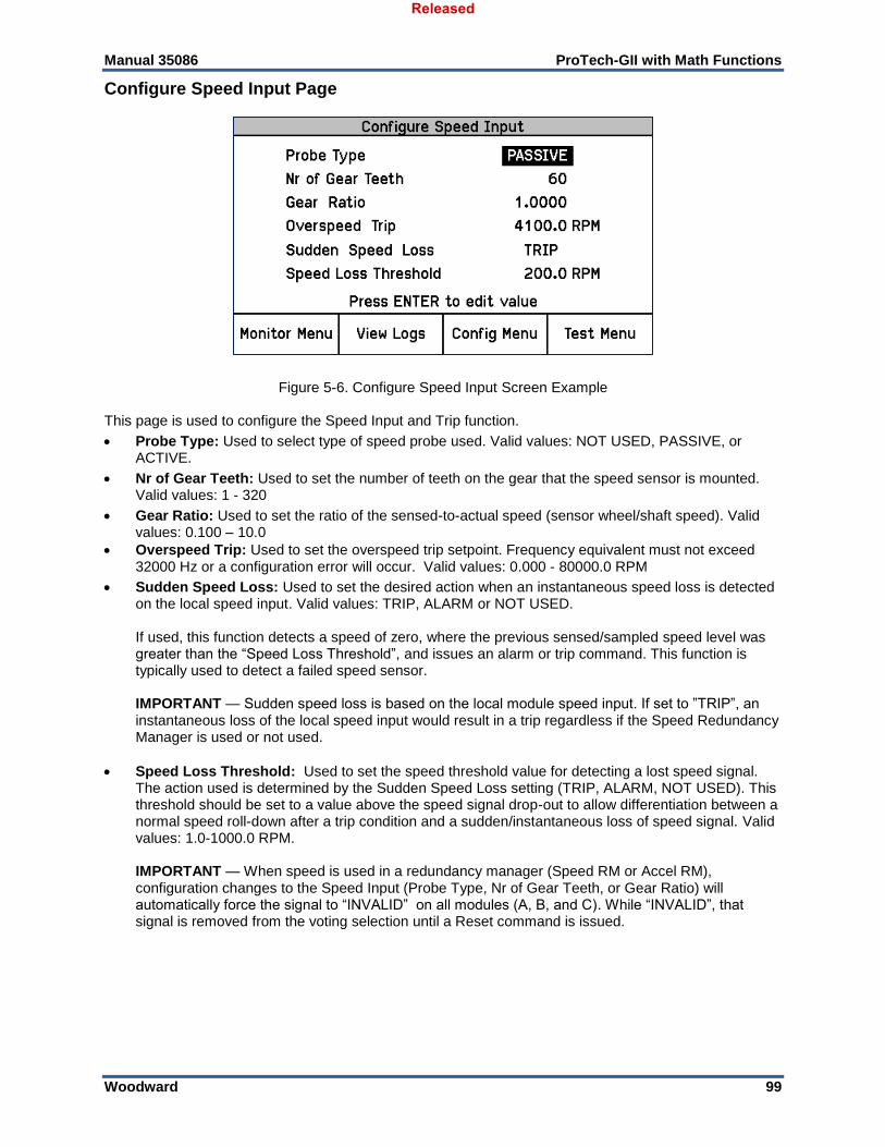
Manual 35086 ProTech-GII with Math Functions
Woodward 99
Configure Speed Input Page
Figure 5-6. Configure Speed Input Screen Example This page is used to configure the Speed Input and Trip function.
Probe Type: Used to select type of speed probe used. Valid values: NOT USED, PASSIVE, or ACTIVE.
Nr of Gear Teeth: Used to set the number of teeth on the gear that the speed sensor is mounted. Valid values: 1 - 320
Gear Ratio: Used to set the ratio of the sensed-to-actual speed (sensor wheel/shaft speed). Valid values: 0.100 – 10.0
Overspeed Trip: Used to set the overspeed trip setpoint. Frequency equivalent must not exceed 32000 Hz or a configuration error will occur. Valid values: 0.000 - 80000.0 RPM
Sudden Speed Loss: Used to set the desired action when an instantaneous speed loss is detected on the local speed input. Valid values: TRIP, ALARM or NOT USED.
If used, this function detects a speed of zero, where the previous sensed/sampled speed level was greater than the “Speed Loss Threshold”, and issues an alarm or trip command. This function is typically used to detect a failed speed sensor. IMPORTANT — Sudden speed loss is based on the local module speed input. If set to ”TRIP”, an instantaneous loss of the local speed input would result in a trip regardless if the Speed Redundancy Manager is used or not used.
Speed Loss Threshold: Used to set the speed threshold value for detecting a lost speed signal. The action used is determined by the Sudden Speed Loss setting (TRIP, ALARM, NOT USED). This threshold should be set to a value above the speed signal drop-out to allow differentiation between a normal speed roll-down after a trip condition and a sudden/instantaneous loss of speed signal. Valid values: 1.0-1000.0 RPM.
IMPORTANT — When speed is used in a redundancy manager (Speed RM or Accel RM), configuration changes to the Speed Input (Probe Type, Nr of Gear Teeth, or Gear Ratio) will automatically force the signal to “INVALID” on all modules (A, B, and C). While “INVALID”, that signal is removed from the voting selection until a Reset command is issued.
Released
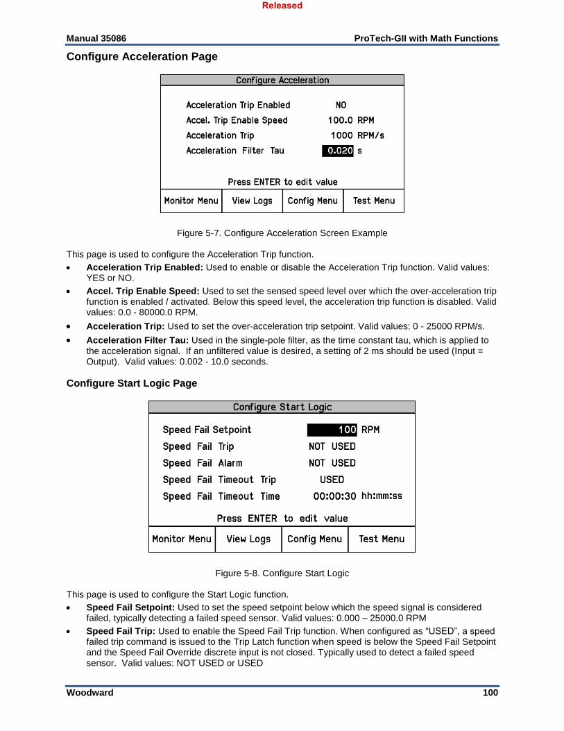
Manual 35086 ProTech-GII with Math Functions
Woodward 100
Configure Acceleration Page
Figure 5-7. Configure Acceleration Screen Example This page is used to configure the Acceleration Trip function.
Acceleration Trip Enabled: Used to enable or disable the Acceleration Trip function. Valid values: YES or NO.
Accel. Trip Enable Speed: Used to set the sensed speed level over which the over-acceleration trip function is enabled / activated. Below this speed level, the acceleration trip function is disabled. Valid values: 0.0 - 80000.0 RPM.
Acceleration Trip: Used to set the over-acceleration trip setpoint. Valid values: 0 - 25000 RPM/s.
Acceleration Filter Tau: Used in the single-pole filter, as the time constant tau, which is applied to the acceleration signal. If an unfiltered value is desired, a setting of 2 ms should be used (Input = Output). Valid values: 0.002 - 10.0 seconds.
Configure Start Logic Page
Figure 5-8. Configure Start Logic This page is used to configure the Start Logic function.
Speed Fail Setpoint: Used to set the speed setpoint below which the speed signal is considered failed, typically detecting a failed speed sensor. Valid values: 0.000 – 25000.0 RPM
Speed Fail Trip: Used to enable the Speed Fail Trip function. When configured as “USED”, a speed failed trip command is issued to the Trip Latch function when speed is below the Speed Fail Setpoint and the Speed Fail Override discrete input is not closed. Typically used to detect a failed speed sensor. Valid values: NOT USED or USED
Released
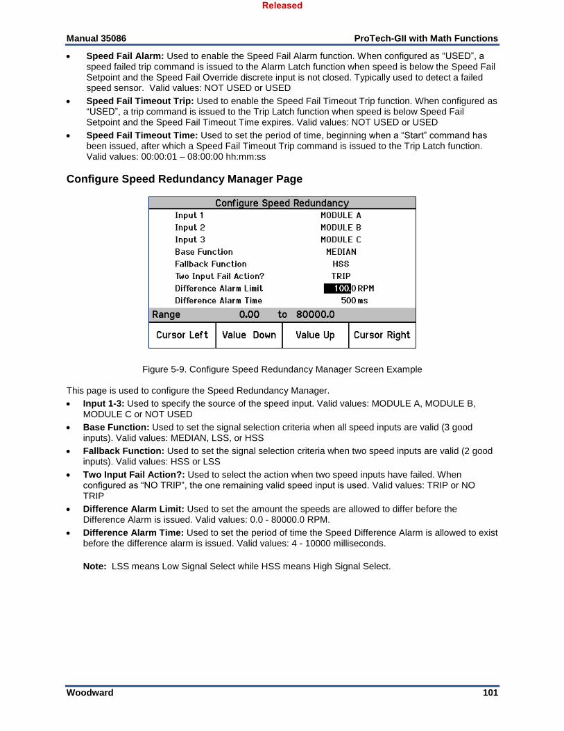
Manual 35086 ProTech-GII with Math Functions
Woodward 101
Speed Fail Alarm: Used to enable the Speed Fail Alarm function. When configured as “USED”, a speed failed trip command is issued to the Alarm Latch function when speed is below the Speed Fail Setpoint and the Speed Fail Override discrete input is not closed. Typically used to detect a failed speed sensor. Valid values: NOT USED or USED
Speed Fail Timeout Trip: Used to enable the Speed Fail Timeout Trip function. When configured as “USED”, a trip command is issued to the Trip Latch function when speed is below Speed Fail Setpoint and the Speed Fail Timeout Time expires. Valid values: NOT USED or USED
Speed Fail Timeout Time: Used to set the period of time, beginning when a “Start” command has been issued, after which a Speed Fail Timeout Trip command is issued to the Trip Latch function. Valid values: 00:00:01 – 08:00:00 hh:mm:ss
Configure Speed Redundancy Manager Page
Figure 5-9. Configure Speed Redundancy Manager Screen Example This page is used to configure the Speed Redundancy Manager.
Input 1-3: Used to specify the source of the speed input. Valid values: MODULE A, MODULE B, MODULE C or NOT USED
Base Function: Used to set the signal selection criteria when all speed inputs are valid (3 good inputs). Valid values: MEDIAN, LSS, or HSS
Fallback Function: Used to set the signal selection criteria when two speed inputs are valid (2 good inputs). Valid values: HSS or LSS
Two Input Fail Action?: Used to select the action when two speed inputs have failed. When configured as “NO TRIP”, the one remaining valid speed input is used. Valid values: TRIP or NO TRIP
Difference Alarm Limit: Used to set the amount the speeds are allowed to differ before the Difference Alarm is issued. Valid values: 0.0 - 80000.0 RPM.
Difference Alarm Time: Used to set the period of time the Speed Difference Alarm is allowed to exist before the difference alarm is issued. Valid values: 4 - 10000 milliseconds.
Note: LSS means Low Signal Select while HSS means High Signal Select.
Released
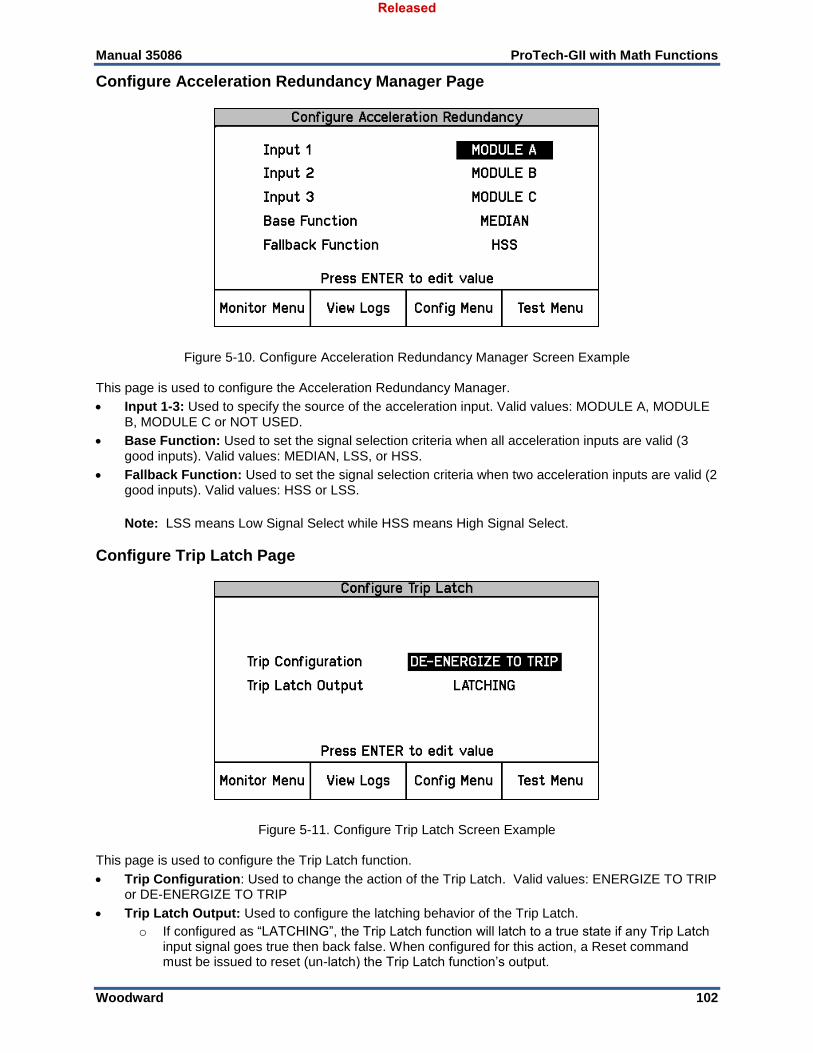
Manual 35086 ProTech-GII with Math Functions
Woodward 102
Configure Acceleration Redundancy Manager Page
Figure 5-10. Configure Acceleration Redundancy Manager Screen Example This page is used to configure the Acceleration Redundancy Manager.
Input 1-3: Used to specify the source of the acceleration input. Valid values: MODULE A, MODULE B, MODULE C or NOT USED.
Base Function: Used to set the signal selection criteria when all acceleration inputs are valid (3 good inputs). Valid values: MEDIAN, LSS, or HSS.
Fallback Function: Used to set the signal selection criteria when two acceleration inputs are valid (2 good inputs). Valid values: HSS or LSS.
Note: LSS means Low Signal Select while HSS means High Signal Select.
Configure Trip Latch Page
Figure 5-11. Configure Trip Latch Screen Example This page is used to configure the Trip Latch function.
Trip Configuration: Used to change the action of the Trip Latch. Valid values: ENERGIZE TO TRIP or DE-ENERGIZE TO TRIP
Trip Latch Output: Used to configure the latching behavior of the Trip Latch.
o If configured as “LATCHING”, the Trip Latch function will latch to a true state if any Trip Latch input signal goes true then back false. When configured for this action, a Reset command must be issued to reset (un-latch) the Trip Latch function’s output.
Released
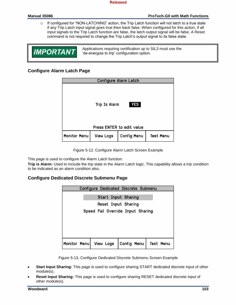
Manual 35086 ProTech-GII with Math Functions
Woodward 103
o If configured for “NON-LATCHING” action, the Trip Latch function will not latch to a true state if any Trip Latch input signal goes true then back false. When configured for this action, if all input signals to the Trip Latch function are false, the latch output signal will be false. A Reset command is not required to change the Trip Latch’s output signal to its false state.
Applications requiring certification up to SIL3 must use the ‘de-energize to trip’ configuration option.
Configure Alarm Latch Page
Figure 5-12. Configure Alarm Latch Screen Example This page is used to configure the Alarm Latch function.
Trip is Alarm: Used to include the trip state in the Alarm Latch logic. This capability allows a trip condition to be indicated as an alarm condition also.
Configure Dedicated Discrete Submenu Page
Figure 5-13. Configure Dedicated Discrete Submenu Screen Example
Start Input Sharing: This page is used to configure sharing START dedicated discrete input of other module(s).
Reset Input Sharing: This page is used to configure sharing RESET dedicated discrete input of other module(s).
Released
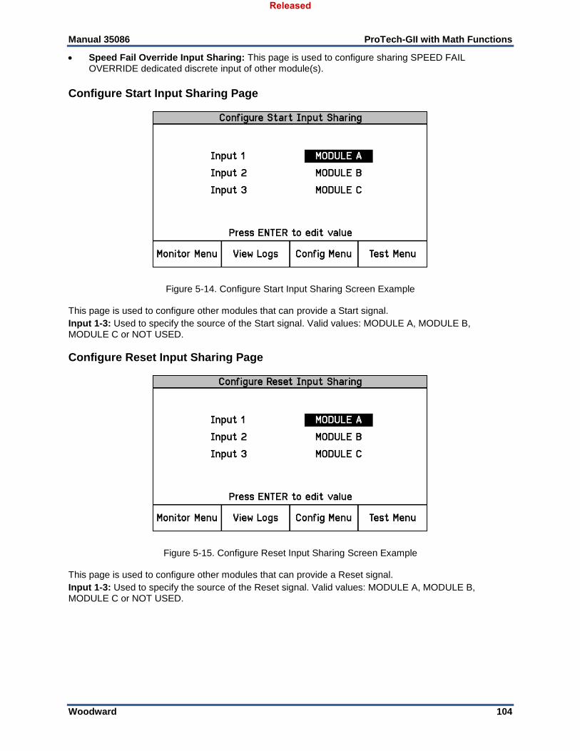
Manual 35086 ProTech-GII with Math Functions
Woodward 104
Speed Fail Override Input Sharing: This page is used to configure sharing SPEED FAIL OVERRIDE dedicated discrete input of other module(s).
Configure Start Input Sharing Page
Figure 5-14. Configure Start Input Sharing Screen Example This page is used to configure other modules that can provide a Start signal.
Input 1-3: Used to specify the source of the Start signal. Valid values: MODULE A, MODULE B, MODULE C or NOT USED.
Configure Reset Input Sharing Page
Figure 5-15. Configure Reset Input Sharing Screen Example This page is used to configure other modules that can provide a Reset signal.
Input 1-3: Used to specify the source of the Reset signal. Valid values: MODULE A, MODULE B, MODULE C or NOT USED.
Released
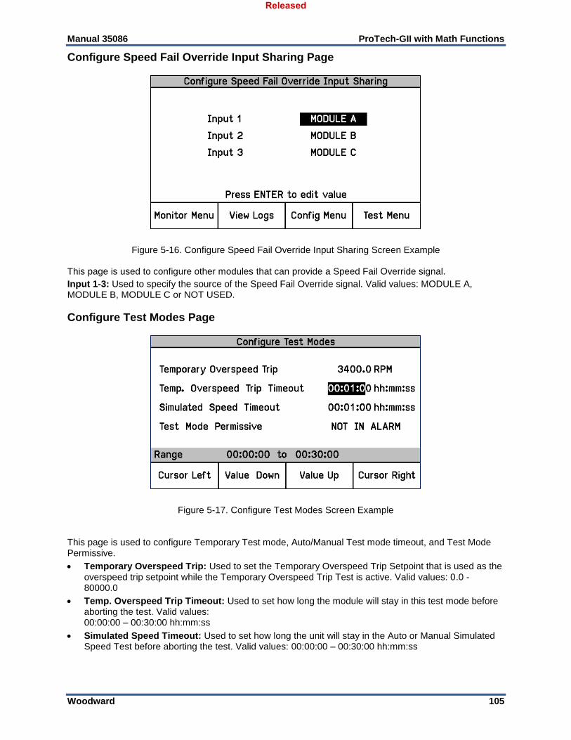
Manual 35086 ProTech-GII with Math Functions
Woodward 105
Configure Speed Fail Override Input Sharing Page
Figure 5-16. Configure Speed Fail Override Input Sharing Screen Example This page is used to configure other modules that can provide a Speed Fail Override signal.
Input 1-3: Used to specify the source of the Speed Fail Override signal. Valid values: MODULE A, MODULE B, MODULE C or NOT USED.
Configure Test Modes Page
Figure 5-17. Configure Test Modes Screen Example This page is used to configure Temporary Test mode, Auto/Manual Test mode timeout, and Test Mode Permissive.
Temporary Overspeed Trip: Used to set the Temporary Overspeed Trip Setpoint that is used as the overspeed trip setpoint while the Temporary Overspeed Trip Test is active. Valid values: 0.0 - 80000.0
Temp. Overspeed Trip Timeout: Used to set how long the module will stay in this test mode before aborting the test. Valid values: 00:00:00 – 00:30:00 hh:mm:ss
Simulated Speed Timeout: Used to set how long the unit will stay in the Auto or Manual Simulated Speed Test before aborting the test. Valid values: 00:00:00 – 00:30:00 hh:mm:ss
Released
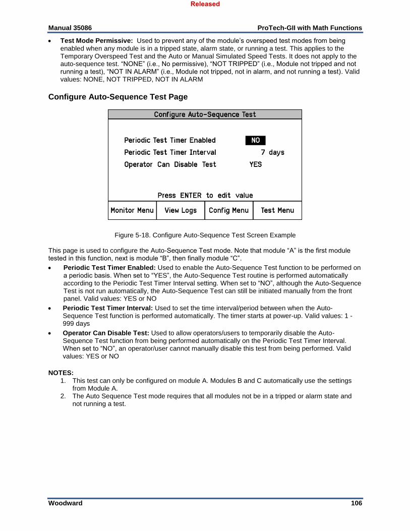
Manual 35086 ProTech-GII with Math Functions
Woodward 106
Test Mode Permissive: Used to prevent any of the module’s overspeed test modes from being enabled when any module is in a tripped state, alarm state, or running a test. This applies to the Temporary Overspeed Test and the Auto or Manual Simulated Speed Tests. It does not apply to the auto-sequence test. “NONE” (i.e., No permissive), “NOT TRIPPED” (i.e., Module not tripped and not running a test), “NOT IN ALARM” (i.e., Module not tripped, not in alarm, and not running a test). Valid values: NONE, NOT TRIPPED, NOT IN ALARM
Configure Auto-Sequence Test Page
Figure 5-18. Configure Auto-Sequence Test Screen Example This page is used to configure the Auto-Sequence Test mode. Note that module “A” is the first module tested in this function, next is module “B”, then finally module “C”.
Periodic Test Timer Enabled: Used to enable the Auto-Sequence Test function to be performed on a periodic basis. When set to “YES”, the Auto-Sequence Test routine is performed automatically according to the Periodic Test Timer Interval setting. When set to “NO”, although the Auto-Sequence Test is not run automatically, the Auto-Sequence Test can still be initiated manually from the front panel. Valid values: YES or NO
Periodic Test Timer Interval: Used to set the time interval/period between when the Auto-Sequence Test function is performed automatically. The timer starts at power-up. Valid values: 1 - 999 days
Operator Can Disable Test: Used to allow operators/users to temporarily disable the Auto-Sequence Test function from being performed automatically on the Periodic Test Timer Interval. When set to “NO”, an operator/user cannot manually disable this test from being performed. Valid values: YES or NO
NOTES:
1. This test can only be configured on module A. Modules B and C automatically use the settings from Module A.
2. The Auto Sequence Test mode requires that all modules not be in a tripped or alarm state and not running a test.
Released
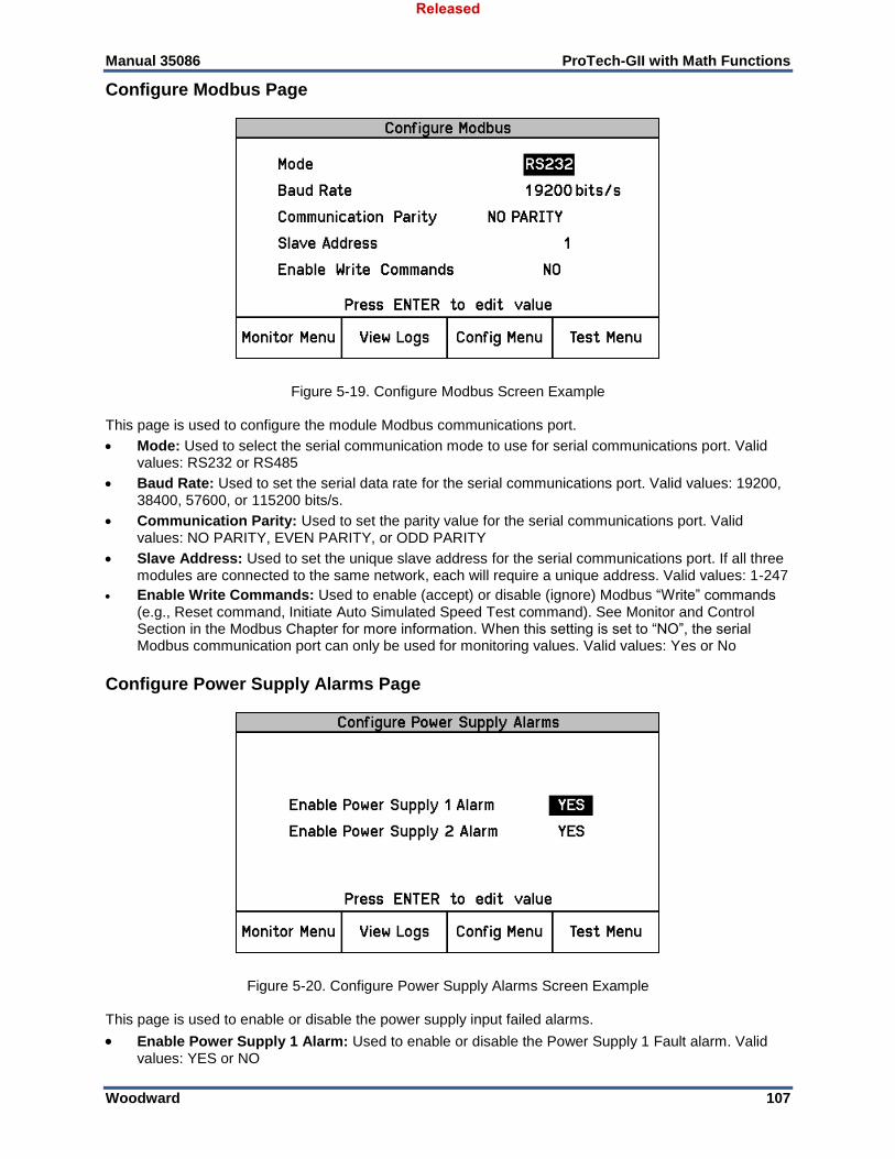
Manual 35086 ProTech-GII with Math Functions
Woodward 107
Configure Modbus Page
Figure 5-19. Configure Modbus Screen Example This page is used to configure the module Modbus communications port.
Mode: Used to select the serial communication mode to use for serial communications port. Valid values: RS232 or RS485
Baud Rate: Used to set the serial data rate for the serial communications port. Valid values: 19200, 38400, 57600, or 115200 bits/s.
Communication Parity: Used to set the parity value for the serial communications port. Valid values: NO PARITY, EVEN PARITY, or ODD PARITY
Slave Address: Used to set the unique slave address for the serial communications port. If all three modules are connected to the same network, each will require a unique address. Valid values: 1-247
Enable Write Commands: Used to enable (accept) or disable (ignore) Modbus “Write” commands (e.g., Reset command, Initiate Auto Simulated Speed Test command). See Monitor and Control Section in the Modbus Chapter for more information. When this setting is set to “NO”, the serial Modbus communication port can only be used for monitoring values. Valid values: Yes or No
Configure Power Supply Alarms Page
Figure 5-20. Configure Power Supply Alarms Screen Example This page is used to enable or disable the power supply input failed alarms.
Enable Power Supply 1 Alarm: Used to enable or disable the Power Supply 1 Fault alarm. Valid values: YES or NO
Released
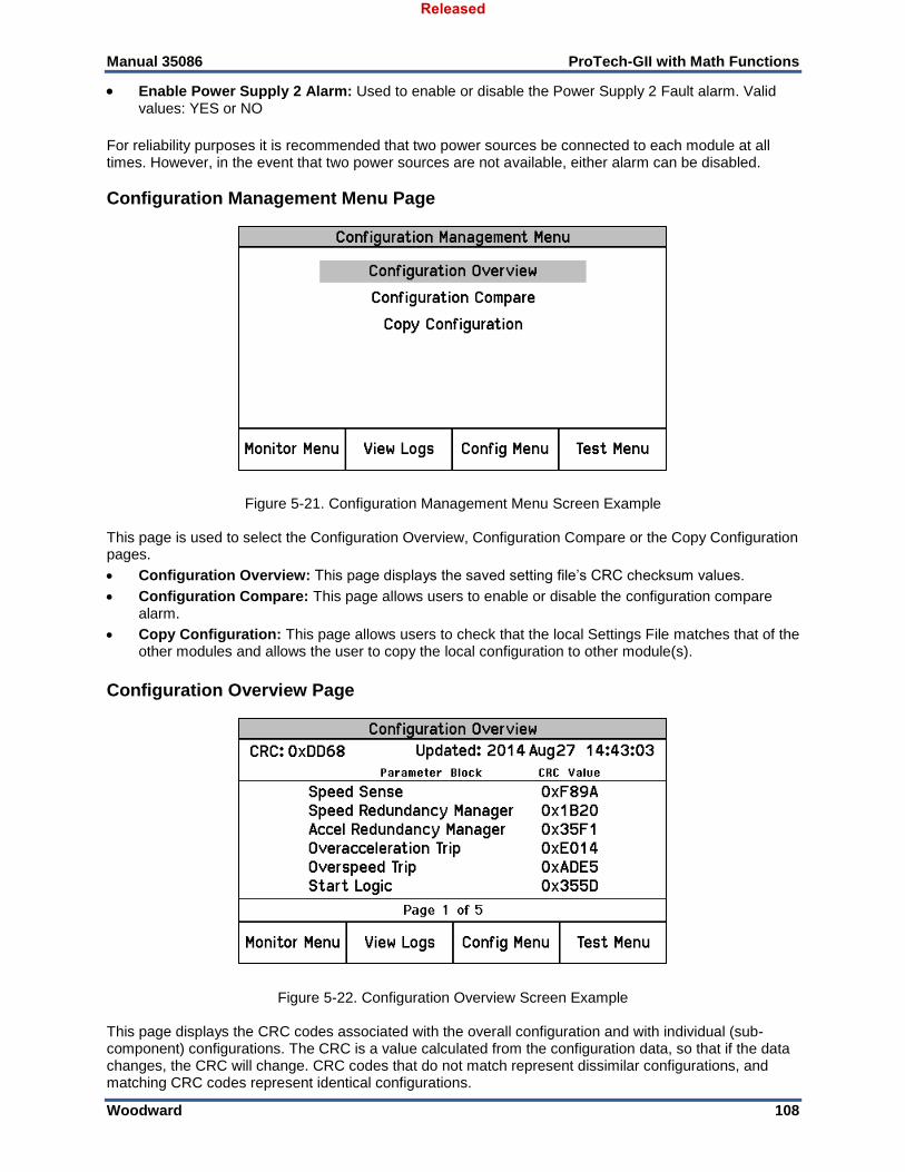
Manual 35086 ProTech-GII with Math Functions
Woodward 108
Enable Power Supply 2 Alarm: Used to enable or disable the Power Supply 2 Fault alarm. Valid values: YES or NO
For reliability purposes it is recommended that two power sources be connected to each module at all times. However, in the event that two power sources are not available, either alarm can be disabled.
Configuration Management Menu Page
Figure 5-21. Configuration Management Menu Screen Example This page is used to select the Configuration Overview, Configuration Compare or the Copy Configuration pages.
Configuration Overview: This page displays the saved setting file’s CRC checksum values.
Configuration Compare: This page allows users to enable or disable the configuration compare alarm.
Copy Configuration: This page allows users to check that the local Settings File matches that of the other modules and allows the user to copy the local configuration to other module(s).
Configuration Overview Page
Figure 5-22. Configuration Overview Screen Example This page displays the CRC codes associated with the overall configuration and with individual (sub-component) configurations. The CRC is a value calculated from the configuration data, so that if the data changes, the CRC will change. CRC codes that do not match represent dissimilar configurations, and matching CRC codes represent identical configurations.
Released
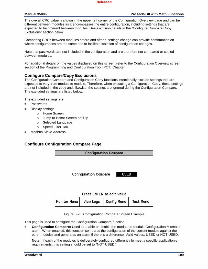
Manual 35086 ProTech-GII with Math Functions
Woodward 109
The overall CRC value is shown in the upper left corner of the Configuration Overview page and can be different between modules as it encompasses the entire configuration, including settings that are expected to be different between modules. See exclusion details in the “Configure Compare/Copy Exclusions” section below. Comparing CRCs between modules before and after a settings change can provide confirmation on where configurations are the same and to facilitate isolation of configuration changes. Note that passwords are not included in the configuration and are therefore not compared or copied between modules. For additional details on the values displayed on this screen, refer to the Configuration Overview screen section of the Programming and Configuration Tool (PCT) Chapter.
Configure Compare/Copy Exclusions The Configuration Compare and Configuration Copy functions intentionally exclude settings that are expected to vary from module to module. Therefore, when executing a Configuration Copy, these settings are not included in the copy and, likewise, the settings are ignored during the Configuration Compare. The excluded settings are listed below. The excluded settings are:
Passwords
Display settings o Home Screen o Jump to Home Screen on Trip o Selected Language o Speed Filter Tau
Modbus Slave Address
Configure Configuration Compare Page
Figure 5-23. Configuration Compare Screen Example This page is used to configure the Configuration Compare function.
Configuration Compare: Used to enable or disable the module-to-module Configuration Mismatch alarm. When enabled, this function compares the configuration of the current module against the other modules and generates an alarm if there is a difference. Valid values: USED or NOT USED.
Note: If each of the modules is deliberately configured differently to meet a specific application’s requirements, this setting should be set to “NOT USED”.
Released
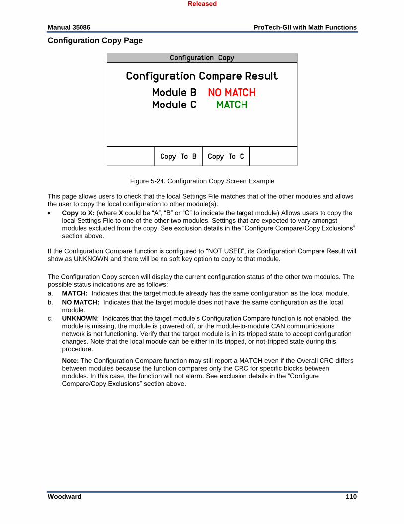
Manual 35086 ProTech-GII with Math Functions
Woodward 110
Configuration Copy Page
Figure 5-24. Configuration Copy Screen Example This page allows users to check that the local Settings File matches that of the other modules and allows the user to copy the local configuration to other module(s).
Copy to X: (where X could be “A”, “B” or “C” to indicate the target module) Allows users to copy the local Settings File to one of the other two modules. Settings that are expected to vary amongst modules excluded from the copy. See exclusion details in the “Configure Compare/Copy Exclusions” section above.
If the Configuration Compare function is configured to “NOT USED”, its Configuration Compare Result will show as UNKNOWN and there will be no soft key option to copy to that module.
The Configuration Copy screen will display the current configuration status of the other two modules. The possible status indications are as follows:
a. MATCH: Indicates that the target module already has the same configuration as the local module.
b. NO MATCH: Indicates that the target module does not have the same configuration as the local module.
c. UNKNOWN: Indicates that the target module’s Configuration Compare function is not enabled, the module is missing, the module is powered off, or the module-to-module CAN communications network is not functioning. Verify that the target module is in its tripped state to accept configuration changes. Note that the local module can be either in its tripped, or not-tripped state during this procedure.
Note: The Configuration Compare function may still report a MATCH even if the Overall CRC differs between modules because the function compares only the CRC for specific blocks between modules. In this case, the function will not alarm. See exclusion details in the “Configure Compare/Copy Exclusions” section above.
Released
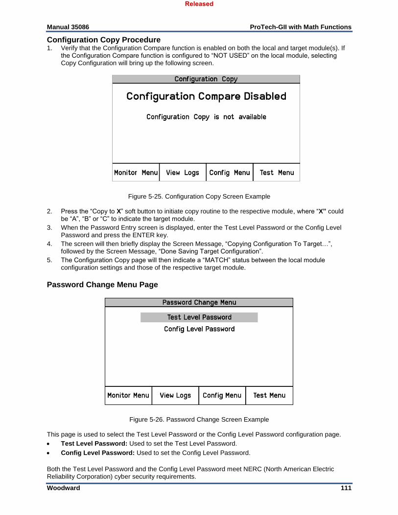
Manual 35086 ProTech-GII with Math Functions
Woodward 111
Configuration Copy Procedure 1. Verify that the Configuration Compare function is enabled on both the local and target module(s). If
the Configuration Compare function is configured to “NOT USED” on the local module, selecting Copy Configuration will bring up the following screen.
Figure 5-25. Configuration Copy Screen Example 2. Press the “Copy to X” soft button to initiate copy routine to the respective module, where “X” could
be “A”, “B” or “C” to indicate the target module.
3. When the Password Entry screen is displayed, enter the Test Level Password or the Config Level Password and press the ENTER key.
4. The screen will then briefly display the Screen Message, “Copying Configuration To Target…”, followed by the Screen Message, “Done Saving Target Configuration”.
5. The Configuration Copy page will then indicate a “MATCH” status between the local module configuration settings and those of the respective target module.
Password Change Menu Page
Figure 5-26. Password Change Screen Example This page is used to select the Test Level Password or the Config Level Password configuration page.
Test Level Password: Used to set the Test Level Password.
Config Level Password: Used to set the Config Level Password.
Both the Test Level Password and the Config Level Password meet NERC (North American Electric Reliability Corporation) cyber security requirements.
Released
Manual 35086 ProTech-GII with Math Functions
Woodward 112
Note: Refer to the Passwords Section of the Front Panel Interface Chapter for details on access levels.
Password Change Procedure: 1. Select the level of password to change.
2. At the Change Password prompt, press the “Yes” soft key to continue, or “Cancel” soft key to back out of this screen.
3. If changing the Test Level Password, enter the current Test Level Password or Config Level Password. If changing the Config Level Password, enter the current Config Level Password.
4. After entering the current password, press the ENTER key.
5. Enter the new password for that level.
a. Use the "Aa 0-9 @" soft key to select upper case letters, lower case letters, numbers, or a list of usable special characters.
b. Use the "Value Down" or "Value Up" keys to change the highlighted value.
c. Use the "Cursor Right" key to move the highlighted character to the right.
6. Once the new password has been entered, press the ENTER key to save.
7. A Password Changed message will appear to confirm that the password has been changed.
Default Test Level Password: AAAAAA (as shipped from factory)
Default Config Level Password: AAAAAA (as shipped from factory)
There is no means to reset the password if it is forgotten. Units requiring a password reset must be returned to Woodward.
Released
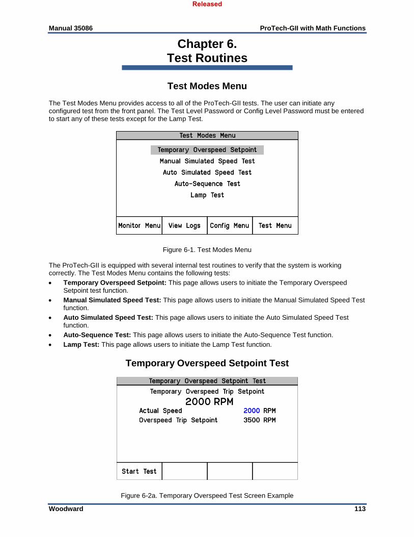
Manual 35086 ProTech-GII with Math Functions
Woodward 113
Chapter 6. Test Routines
Test Modes Menu The Test Modes Menu provides access to all of the ProTech-GII tests. The user can initiate any configured test from the front panel. The Test Level Password or Config Level Password must be entered to start any of these tests except for the Lamp Test.
Figure 6-1. Test Modes Menu The ProTech-GII is equipped with several internal test routines to verify that the system is working correctly. The Test Modes Menu contains the following tests:
Temporary Overspeed Setpoint: This page allows users to initiate the Temporary Overspeed Setpoint test function.
Manual Simulated Speed Test: This page allows users to initiate the Manual Simulated Speed Test function.
Auto Simulated Speed Test: This page allows users to initiate the Auto Simulated Speed Test function.
Auto-Sequence Test: This page allows users to initiate the Auto-Sequence Test function.
Lamp Test: This page allows users to initiate the Lamp Test function.
Temporary Overspeed Setpoint Test
Figure 6-2a. Temporary Overspeed Test Screen Example
Released

Manual 35086 ProTech-GII with Math Functions
Woodward 114
Temporary Overspeed Trip Setpoint: Displays the configured Temporary Overspeed Trip Setpoint setting.
Actual Speed: Displays the sensed actual speed.
Overspeed Trip Setpoint: Displays the current Overspeed Trip setpoint.
This test function, when enabled, temporarily sets the Overspeed Trip to the configured “Temporary Overspeed Trip Setpoint” for the configured “Temp. Overspeed Trip Timeout” period of time, available from the “Configure Test Modes” screen.
Note: If the “Temp. Overspeed Trip Timeout” setting is not configured for greater than zero, an immediate timer expiration occurs and will prevent the test from running.
This setting can be set above or below the module’s “Overspeed Trip” setting. If a secondary overspeed device is used, which has an overspeed trip level that is above the ProTech-GII’s, and then it may be desirable to use this function to temporarily raise the ProTech-GII’s overspeed trip setpoint above the secondary device for testing purposes. If it is desired to not increase the monitored rotating equipment (turbine, generator or compressor) up to its actual overspeed trip level to validate the overspeed trip logic and associated trip circuitry/functions, the “Temporary Overspeed Setpoint” function can be used to temporarily lower the module’s overspeed setpoint to slightly above the rotating equipment’s rated speed level. If set to slightly above the rotating equipment’s rotating speed level, the rotating equipment speed can then be slightly raised until its speed is at or above the “Temporary Overspeed Setpoint” level to validate the related trip circuitry function for proper operation. When this function is enabled, if the rotating equipment’s speed is not taken above the “Temporary Overspeed Setpoint” level within the configured “Temp. Overspeed Trip Time-Out” time span, this test function is aborted, and the module’s “Overspeed Trip” setpoint is set/stepped back to its normal “Overspeed Trip” level/setting. If, during this time, the rotating equipment’s speed is taken above the “Temporary Overspeed Setpoint” level, the module’s Overspeed Trip function will issue a trip command (tripping the module), and the Overspeed Trip setpoint will be set back to its normal “Overspeed Trip” level/setting.
Temporary Overspeed Test Procedure 1. Verify module is not in a tripped state.
2. From the “Temporary Overspeed Setpoint Test” screen, press the “Start Test” soft key.
3. The “Password Entry” screen will appear. Enter the Test Level Password.
4. Press the “Apply” soft key to temporarily change the local “Overspeed Trip” setpoint to the configured “Temporary Overspeed Setpoint” or press the “Cancel” soft key to exit the screen.
5. The “Test Time Remaining” timer will be displayed and will start counting down. Note: If the “Temp. Overspeed Trip Timeout” setting is not configured for greater than zero, an immediate timer expiration occurs, inhibiting display of the timer.
6. The rotating equipment speed (or simulated speed) must then rise above the “Temporary Overspeed Setpoint” to cause a trip condition before the “Test Time Remaining” timer expires.
A user can end this function at any time and restore the Overspeed Trip Setpoint to its normal level by pressing the “End Test” soft key. If the “Test Time Remaining” timer expires before the test has ended, the Screen Message, “Test Time Expired”, will be displayed and the display will revert back to the Start test screen.
Released
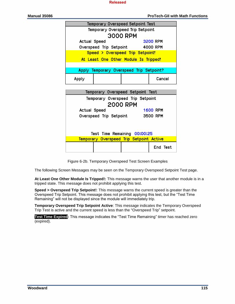
Manual 35086 ProTech-GII with Math Functions
Woodward 115
Figure 6-2b. Temporary Overspeed Test Screen Examples The following Screen Messages may be seen on the Temporary Overspeed Setpoint Test page. At Least One Other Module Is Tripped!: This message warns the user that another module is in a tripped state. This message does not prohibit applying this test.
Speed > Overspeed Trip Setpoint!: This message warns the current speed is greater than the Overspeed Trip Setpoint. This message does not prohibit applying this test, but the “Test Time Remaining” will not be displayed since the module will immediately trip.
Temporary Overspeed Trip Setpoint Active: This message indicates the Temporary Overspeed Trip Test is active and the current speed is less than the “Overspeed Trip” setpoint.
Test Time Expired: This message indicates the “Test Time Remaining” timer has reached zero (expired).
Released
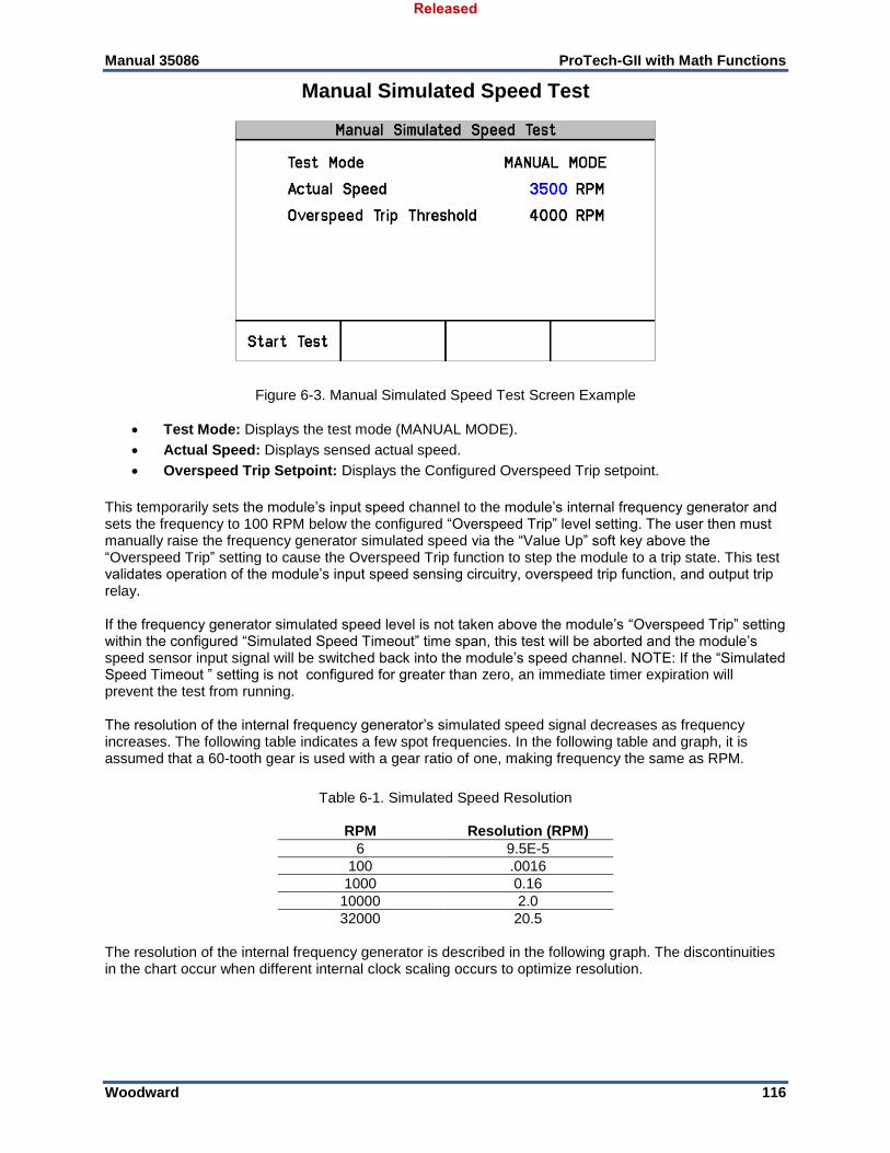
Manual 35086 ProTech-GII with Math Functions
Woodward 116
Manual Simulated Speed Test
Figure 6-3. Manual Simulated Speed Test Screen Example
Test Mode: Displays the test mode (MANUAL MODE).
Actual Speed: Displays sensed actual speed.
Overspeed Trip Setpoint: Displays the Configured Overspeed Trip setpoint.
This temporarily sets the module’s input speed channel to the module’s internal frequency generator and sets the frequency to 100 RPM below the configured “Overspeed Trip” level setting. The user then must manually raise the frequency generator simulated speed via the “Value Up” soft key above the “Overspeed Trip” setting to cause the Overspeed Trip function to step the module to a trip state. This test validates operation of the module’s input speed sensing circuitry, overspeed trip function, and output trip relay. If the frequency generator simulated speed level is not taken above the module’s “Overspeed Trip” setting within the configured “Simulated Speed Timeout” time span, this test will be aborted and the module’s speed sensor input signal will be switched back into the module’s speed channel. NOTE: If the “Simulated Speed Timeout ” setting is not configured for greater than zero, an immediate timer expiration will prevent the test from running. The resolution of the internal frequency generator’s simulated speed signal decreases as frequency increases. The following table indicates a few spot frequencies. In the following table and graph, it is assumed that a 60-tooth gear is used with a gear ratio of one, making frequency the same as RPM.
Table 6-1. Simulated Speed Resolution
RPM Resolution (RPM)
6 9.5E-5
100 .0016
1000 0.16
10000 2.0
32000 20.5 The resolution of the internal frequency generator is described in the following graph. The discontinuities in the chart occur when different internal clock scaling occurs to optimize resolution.
Released
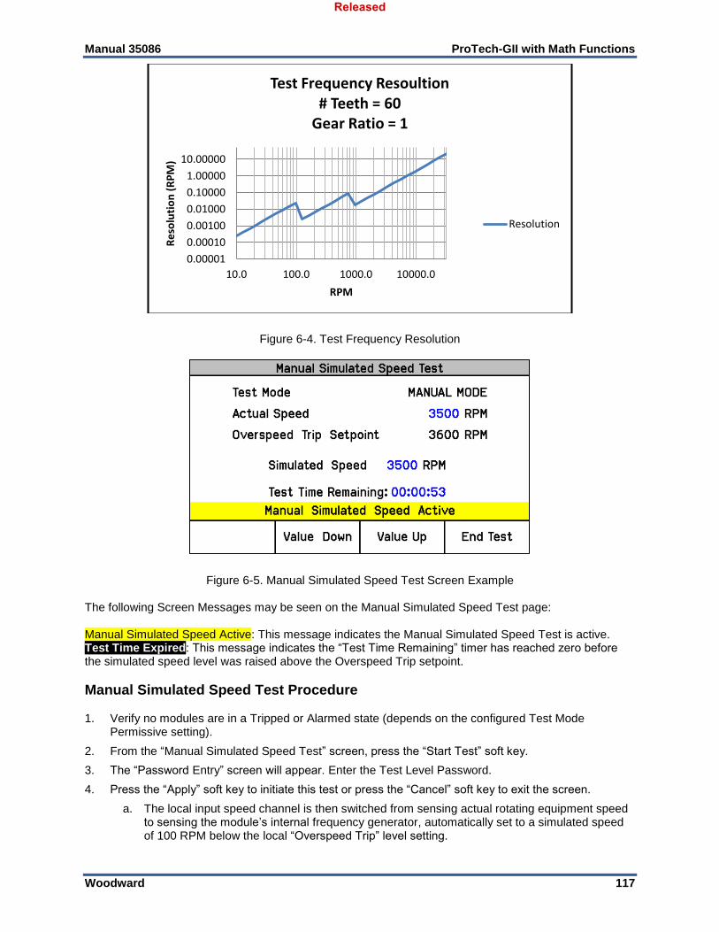
Manual 35086 ProTech-GII with Math Functions
Woodward 117
Figure 6-4. Test Frequency Resolution
Figure 6-5. Manual Simulated Speed Test Screen Example The following Screen Messages may be seen on the Manual Simulated Speed Test page: Manual Simulated Speed Active: This message indicates the Manual Simulated Speed Test is active. Test Time Expired: This message indicates the “Test Time Remaining” timer has reached zero before the simulated speed level was raised above the Overspeed Trip setpoint.
Manual Simulated Speed Test Procedure 1. Verify no modules are in a Tripped or Alarmed state (depends on the configured Test Mode
Permissive setting).
2. From the “Manual Simulated Speed Test” screen, press the “Start Test” soft key.
3. The “Password Entry” screen will appear. Enter the Test Level Password.
4. Press the “Apply” soft key to initiate this test or press the “Cancel” soft key to exit the screen.
a. The local input speed channel is then switched from sensing actual rotating equipment speed to sensing the module’s internal frequency generator, automatically set to a simulated speed of 100 RPM below the local “Overspeed Trip” level setting.
0.00001
0.00010
0.00100
0.01000
0.10000
1.00000
10.00000
10.0 100.0 1000.0 10000.0
Re
solu
tio
n (
RP
M)
RPM
Test Frequency Resoultion# Teeth = 60
Gear Ratio = 1
Resolution
Released
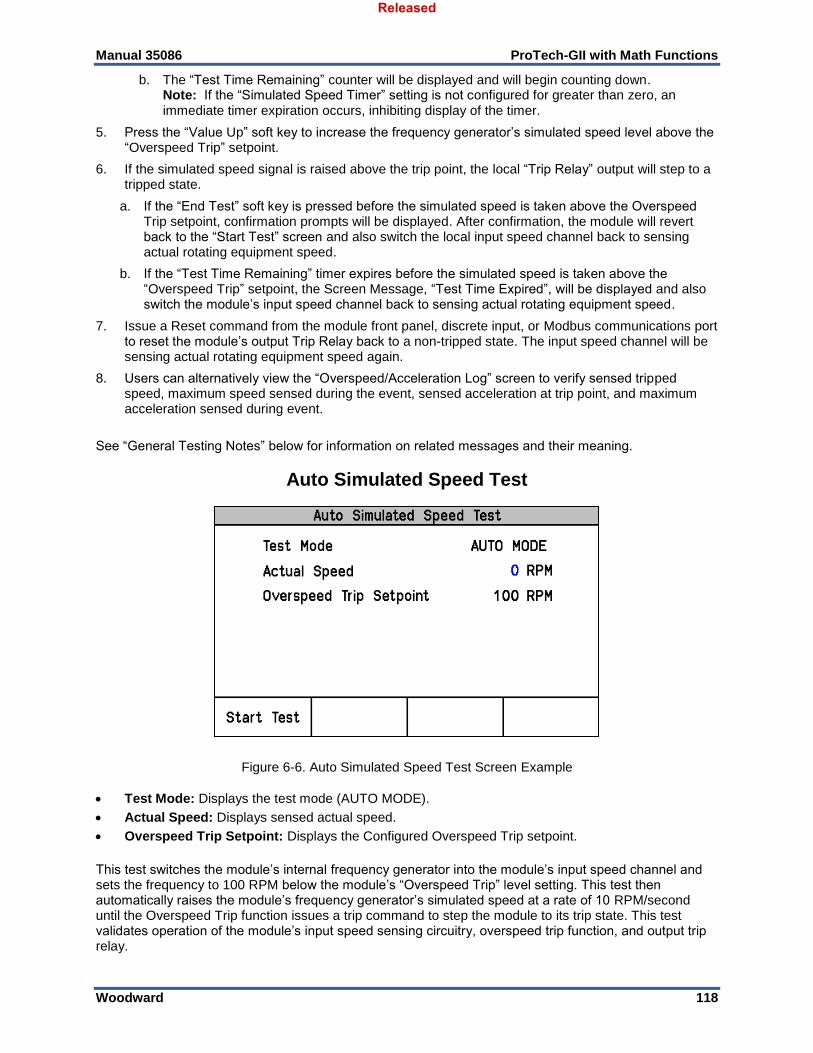
Manual 35086 ProTech-GII with Math Functions
Woodward 118
b. The “Test Time Remaining” counter will be displayed and will begin counting down. Note: If the “Simulated Speed Timer” setting is not configured for greater than zero, an immediate timer expiration occurs, inhibiting display of the timer.
5. Press the “Value Up” soft key to increase the frequency generator’s simulated speed level above the “Overspeed Trip” setpoint.
6. If the simulated speed signal is raised above the trip point, the local “Trip Relay” output will step to a tripped state.
a. If the “End Test” soft key is pressed before the simulated speed is taken above the Overspeed Trip setpoint, confirmation prompts will be displayed. After confirmation, the module will revert back to the “Start Test” screen and also switch the local input speed channel back to sensing actual rotating equipment speed.
b. If the “Test Time Remaining” timer expires before the simulated speed is taken above the “Overspeed Trip” setpoint, the Screen Message, “Test Time Expired”, will be displayed and also switch the module’s input speed channel back to sensing actual rotating equipment speed.
7. Issue a Reset command from the module front panel, discrete input, or Modbus communications port to reset the module’s output Trip Relay back to a non-tripped state. The input speed channel will be sensing actual rotating equipment speed again.
8. Users can alternatively view the “Overspeed/Acceleration Log” screen to verify sensed tripped speed, maximum speed sensed during the event, sensed acceleration at trip point, and maximum acceleration sensed during event.
See “General Testing Notes” below for information on related messages and their meaning.
Auto Simulated Speed Test
Figure 6-6. Auto Simulated Speed Test Screen Example
Test Mode: Displays the test mode (AUTO MODE).
Actual Speed: Displays sensed actual speed.
Overspeed Trip Setpoint: Displays the Configured Overspeed Trip setpoint.
This test switches the module’s internal frequency generator into the module’s input speed channel and sets the frequency to 100 RPM below the module’s “Overspeed Trip” level setting. This test then automatically raises the module’s frequency generator’s simulated speed at a rate of 10 RPM/second until the Overspeed Trip function issues a trip command to step the module to its trip state. This test validates operation of the module’s input speed sensing circuitry, overspeed trip function, and output trip relay.
Released

Manual 35086 ProTech-GII with Math Functions
Woodward 119
If the frequency generator’s simulated speed level does not reach the module’s Overspeed Trip” setting within 12 seconds, this test will be aborted and the module’s input speed channel will be switched back to sensing actual rotating equipment speed. The following Screen Messages may be seen on the Auto Simulated Speed Test page: Auto Simulated Speed Active: This message indicates the Auto Simulated Speed Test is active.
Test Ended by Modbus: This message indicates the test was ended by a Modbus command.
Test Time Expired: This message indicates the 12-second timer has reached zero before the simulated speed level was raised above the Overspeed Trip setpoint.
Auto Simulated Speed Test Procedure 1. Verify no modules are in a Tripped or Alarmed state (depends on the configured Test Mode
Permissive setting).
2. From the module’s Auto Simulated Speed Test Screen, press the “Start Test” soft key or from the Modbus interface (if write commands have been configured/enabled) give an “Initiate Auto Simulated Speed Test” command then a “Confirm Auto Simulated Speed Test” command.
a. Note: This test routine can also be initiated by the Auto Sequence Test routine (periodically or manually).
3. If the module’s front panel is used to initiate this test, then the “Password Entry” screen will appear. Enter the Test Level Password.
4. If the front panel is used to initiate this test then press the “Apply” soft key to initiate this test or press the “Cancel” soft key to exit the screen.
5. When this test routine is started, the module’s input speed channel is then switched from sensing actual rotating equipment speed to sensing the module’s internal frequency generator which is automatically set to a simulated speed of 100 RPM below the module’s “Overspeed Trip” level setting.
a. The internal frequency generator will then automatically ramp the simulated speed signal at a rate of 10 RPM/second up to and above the module’s Overspeed Trip level setting.
b. A 12-second timeout timer will start running.
6. If the modules frequency generator’s simulated speed signal increases up to or above the module’s Overspeed Trip level, the module’s output “Trip Relay” will step to a tripped state.
a. If the screen’s “End Test” soft key is pressed before the simulated speed is taken up to or above the Overspeed Trip setpoint, the module will revert back to the “Start Test” screen and also switch the module’s input speed channel back to sensing actual rotating equipment speed.
b. If the 12-second timer expires before the simulated speed is taken up to or above the Overspeed Trip setpoint, the module will display a message “Test Time Expired and revert back to the “Start Test” screen and also switch the module’s input speed channel back to sensing actual rotating equipment speed.
c. If a Modbus interface command to “Abort Auto Simulated Speed Test” is given before the simulated speed is increased up to or above the Overspeed Trip setpoint, the module will revert back to the “Start Test” screen and also switch the module’s input speed channel back to sensing actual rotating equipment speed.
7. Issue a Reset command from either the module front panel, discrete input, or the Modbus interface to reset the module’s output Trip Relay back to its non-tripped state. The input speed channel will be sensing actual rotating equipment speed again.
8. Users can alternatively view the “Overspeed/Acceleration Log” screen to verify sensed trip speed, maximum speed sensed during the event, sensed acceleration at trip point, and maximum acceleration sensed during event.
See “General Testing Notes” below for information on related messages and their meaning.
Released
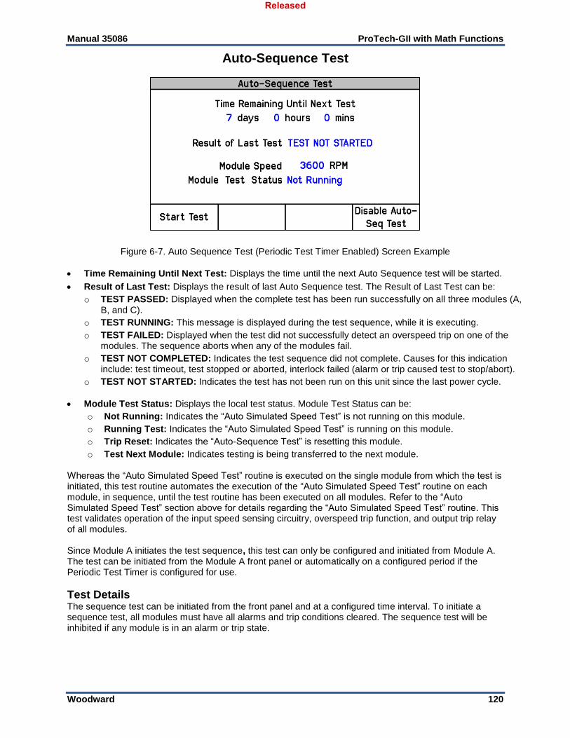
Manual 35086 ProTech-GII with Math Functions
Woodward 120
Auto-Sequence Test
Figure 6-7. Auto Sequence Test (Periodic Test Timer Enabled) Screen Example
Time Remaining Until Next Test: Displays the time until the next Auto Sequence test will be started.
Result of Last Test: Displays the result of last Auto Sequence test. The Result of Last Test can be:
o TEST PASSED: Displayed when the complete test has been run successfully on all three modules (A, B, and C).
o TEST RUNNING: This message is displayed during the test sequence, while it is executing.
o TEST FAILED: Displayed when the test did not successfully detect an overspeed trip on one of the modules. The sequence aborts when any of the modules fail.
o TEST NOT COMPLETED: Indicates the test sequence did not complete. Causes for this indication include: test timeout, test stopped or aborted, interlock failed (alarm or trip caused test to stop/abort).
o TEST NOT STARTED: Indicates the test has not been run on this unit since the last power cycle.
Module Test Status: Displays the local test status. Module Test Status can be:
o Not Running: Indicates the “Auto Simulated Speed Test” is not running on this module.
o Running Test: Indicates the “Auto Simulated Speed Test” is running on this module.
o Trip Reset: Indicates the “Auto-Sequence Test” is resetting this module.
o Test Next Module: Indicates testing is being transferred to the next module. Whereas the “Auto Simulated Speed Test” routine is executed on the single module from which the test is initiated, this test routine automates the execution of the “Auto Simulated Speed Test” routine on each module, in sequence, until the test routine has been executed on all modules. Refer to the “Auto Simulated Speed Test” section above for details regarding the “Auto Simulated Speed Test” routine. This test validates operation of the input speed sensing circuitry, overspeed trip function, and output trip relay of all modules. Since Module A initiates the test sequence, this test can only be configured and initiated from Module A. The test can be initiated from the Module A front panel or automatically on a configured period if the Periodic Test Timer is configured for use.
Test Details The sequence test can be initiated from the front panel and at a configured time interval. To initiate a sequence test, all modules must have all alarms and trip conditions cleared. The sequence test will be inhibited if any module is in an alarm or trip state.
Released

Manual 35086 ProTech-GII with Math Functions
Woodward 121
Once initiated, the Module A speed changes to the internal function generated speed, starting at 100 RPM below the overspeed trip threshold and ramping up until an overspeed trip event occurs on Module A. The Module A speed input is re-activated and the trip output is cleared after three seconds. After another 10 seconds, the same process is initiated on Module B. After Module B trips, the trip output is cleared and the 10-second inter-module test delay elapses, the same process is initiated on Module C. After Module C trips and subsequently resets, the sequence test is complete. Once initiated, the “Result of Last Test” shows “TEST RUNNING”. The status changes to “TEST PASSED” if the entire sequence was successful, otherwise the status changes to “TEST NOT COMPLETED” or “TEST FAILED”. All front panel screens display the same status. While a module is in a test active state, a local alarm is indicated and the local “Module Test Status” is displayed as “Running Test”. If an unrelated trip or alarm occurs on any module before the sequence test completes, the sequence test aborts. The operator can disable the Auto-Sequence Test from the front panel of the module. When the Auto-Sequence Test is disabled or if any module is in trip, alarm, or test, the “Time Remaining Until Next Test” will be prevented from counting below one hour. If the timer is already below one hour, it will be increased to 1 hour. When the Auto-Sequence Test is enabled again and no modules are in trip, alarm, or test, this limit on the timer will no longer be in effect.
Auto Sequence Test Procedure To configure this test, refer to the Configure Auto Sequence Test section of the Configuration Using the Front Panel chapter. To run this test, perform the following steps.
1. Verify no modules are in a Tripped or Alarmed state. (The Test Mode Permissive setting does not apply to this test.)
2. On the “Auto-Sequence Test” screen of Module A, press the “Start Test” soft key.
NOTE: This test routine can also be initiated automatically on a configured period if the Periodic Test Timer is configured for use.
3. The “Password Entry” screen will appear. Enter the Test Level Password.
4. On the “Auto-Sequence Test” screen of Module A, press the “Start Test” soft key to initiate this test or press the “Cancel” soft key to exit the screen.
5. Module A will then perform an Auto Simulated Speed Test. Module A will trip on the simulated overspeed test, then after three seconds reset back to a non-tripped state. A 10-second inter-module test delay is applied before continuing.
6. If all test permissives are met (no module in a tripped or alarmed state), then Module B will perform an Auto Simulated Speed Test.
7. Module B will trip on the simulated overspeed test, then after three seconds reset back to a non-tripped state. A 10-second inter-module test delay is applied before continuing.
8. If all test permissives are met (no module in a tripped or alarmed state), then Module C will perform an Auto Simulated Speed Test.
9. Module C will be reset back to a non-tripped state.
10. Module C will trip on the simulated overspeed test, then after three seconds reset back to a non-tripped state.
11. If, at any point, the permissives are not met (any module in a tripped or alarmed state), the test will abort and the “Result of Last Test” and “Module Test Status” will be updated.
12. If this test was initiated by the “Periodic Test Timer” function, the “Time Remaining Until Next Test” time will be reset and start counting down once again.
Alternatively an operator can configure the Periodic Test Timer function from the front panel of Module A. When this function is disabled, or if any module is in trip, alarm, or test, the “Time Remaining Until Next Test” will be prevented from counting below 1 hour. If the timer is already below one hour it will be increased to one hour. When the Periodic Test Timer function is re-enabled and no modules are tripped, in alarm, or in a test mode, the Periodic Test Timer function will continue to operate as normal. See “General Testing Notes” below for information on related messages and their meaning.
Released
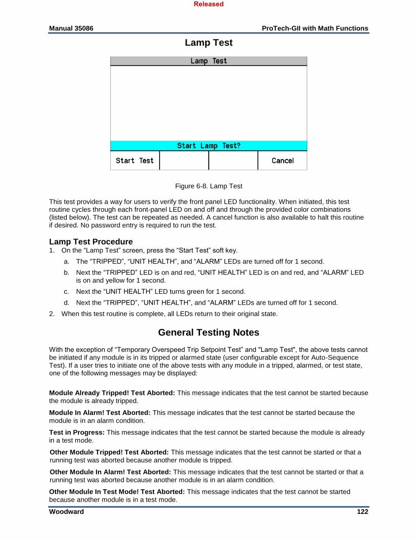
Manual 35086 ProTech-GII with Math Functions
Woodward 122
Lamp Test
Figure 6-8. Lamp Test This test provides a way for users to verify the front panel LED functionality. When initiated, this test routine cycles through each front-panel LED on and off and through the provided color combinations (listed below). The test can be repeated as needed. A cancel function is also available to halt this routine if desired. No password entry is required to run the test.
Lamp Test Procedure 1. On the “Lamp Test” screen, press the “Start Test” soft key.
a. The “TRIPPED”, “UNIT HEALTH”, and “ALARM” LEDs are turned off for 1 second.
b. Next the “TRIPPED” LED is on and red, “UNIT HEALTH” LED is on and red, and “ALARM” LED is on and yellow for 1 second.
c. Next the “UNIT HEALTH” LED turns green for 1 second.
d. Next the “TRIPPED”, “UNIT HEALTH”, and “ALARM” LEDs are turned off for 1 second.
2. When this test routine is complete, all LEDs return to their original state.
General Testing Notes With the exception of “Temporary Overspeed Trip Setpoint Test” and "Lamp Test", the above tests cannot be initiated if any module is in its tripped or alarmed state (user configurable except for Auto-Sequence Test). If a user tries to initiate one of the above tests with any module in a tripped, alarmed, or test state, one of the following messages may be displayed:
Module Already Tripped! Test Aborted: This message indicates that the test cannot be started because the module is already tripped.
Module In Alarm! Test Aborted: This message indicates that the test cannot be started because the module is in an alarm condition.
Test in Progress: This message indicates that the test cannot be started because the module is already in a test mode.
Other Module Tripped! Test Aborted: This message indicates that the test cannot be started or that a running test was aborted because another module is tripped.
Other Module In Alarm! Test Aborted: This message indicates that the test cannot be started or that a running test was aborted because another module is in an alarm condition.
Other Module In Test Mode! Test Aborted: This message indicates that the test cannot be started because another module is in a test mode.
Released
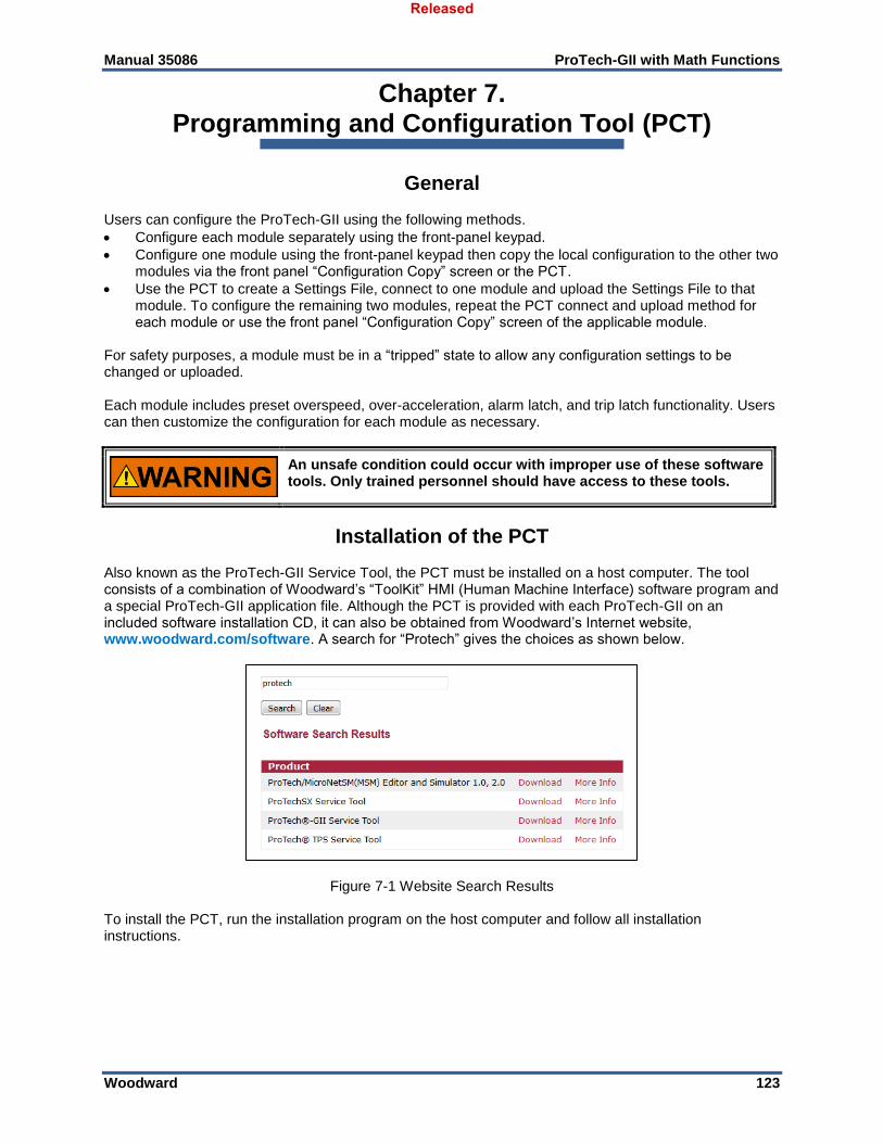
Manual 35086 ProTech-GII with Math Functions
Woodward 123
Chapter 7. Programming and Configuration Tool (PCT)
General Users can configure the ProTech-GII using the following methods.
Configure each module separately using the front-panel keypad.
Configure one module using the front-panel keypad then copy the local configuration to the other two modules via the front panel “Configuration Copy” screen or the PCT.
Use the PCT to create a Settings File, connect to one module and upload the Settings File to that module. To configure the remaining two modules, repeat the PCT connect and upload method for each module or use the front panel “Configuration Copy” screen of the applicable module.
For safety purposes, a module must be in a “tripped” state to allow any configuration settings to be changed or uploaded. Each module includes preset overspeed, over-acceleration, alarm latch, and trip latch functionality. Users can then customize the configuration for each module as necessary.
An unsafe condition could occur with improper use of these software tools. Only trained personnel should have access to these tools.
Installation of the PCT Also known as the ProTech-GII Service Tool, the PCT must be installed on a host computer. The tool consists of a combination of Woodward’s “ToolKit” HMI (Human Machine Interface) software program and a special ProTech-GII application file. Although the PCT is provided with each ProTech-GII on an included software installation CD, it can also be obtained from Woodward’s Internet website, www.woodward.com/software. A search for “Protech” gives the choices as shown below.
Figure 7-1 Website Search Results To install the PCT, run the installation program on the host computer and follow all installation instructions.
Released
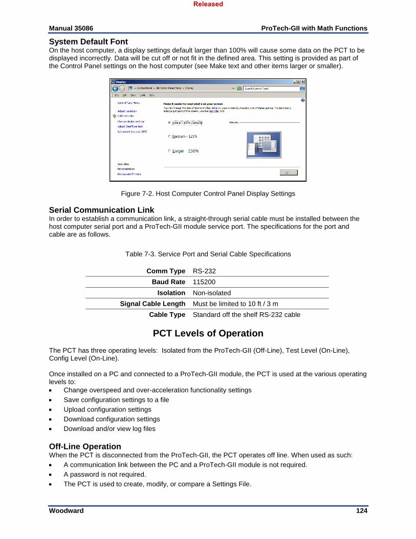
Manual 35086 ProTech-GII with Math Functions
Woodward 124
System Default Font On the host computer, a display settings default larger than 100% will cause some data on the PCT to be displayed incorrectly. Data will be cut off or not fit in the defined area. This setting is provided as part of the Control Panel settings on the host computer (see Make text and other items larger or smaller).
Figure 7-2. Host Computer Control Panel Display Settings
Serial Communication Link In order to establish a communication link, a straight-through serial cable must be installed between the host computer serial port and a ProTech-GII module service port. The specifications for the port and cable are as follows.
Table 7-3. Service Port and Serial Cable Specifications
Comm Type RS-232
Baud Rate 115200
Isolation Non-isolated
Signal Cable Length Must be limited to 10 ft / 3 m
Cable Type Standard off the shelf RS-232 cable
PCT Levels of Operation The PCT has three operating levels: Isolated from the ProTech-GII (Off-Line), Test Level (On-Line), Config Level (On-Line). Once installed on a PC and connected to a ProTech-GII module, the PCT is used at the various operating levels to:
Change overspeed and over-acceleration functionality settings
Save configuration settings to a file
Upload configuration settings
Download configuration settings
Download and/or view log files
Off-Line Operation When the PCT is disconnected from the ProTech-GII, the PCT operates off line. When used as such:
A communication link between the PC and a ProTech-GII module is not required.
A password is not required.
The PCT is used to create, modify, or compare a Settings File.
Released
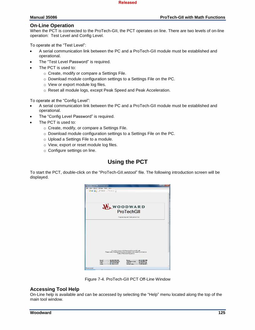
Manual 35086 ProTech-GII with Math Functions
Woodward 125
On-Line Operation When the PCT is connected to the ProTech-GII, the PCT operates on line. There are two levels of on-line operation: Test Level and Config Level. To operate at the “Test Level”:
A serial communication link between the PC and a ProTech-GII module must be established and operational.
The “Test Level Password” is required.
The PCT is used to:
o Create, modify or compare a Settings File.
o Download module configuration settings to a Settings File on the PC.
o View or export module log files.
o Reset all module logs, except Peak Speed and Peak Acceleration.
To operate at the “Config Level”:
A serial communication link between the PC and a ProTech-GII module must be established and operational.
The “Config Level Password” is required.
The PCT is used to:
o Create, modify, or compare a Settings File.
o Download module configuration settings to a Settings File on the PC.
o Upload a Settings File to a module.
o View, export or reset module log files.
o Configure settings on line.
Using the PCT To start the PCT, double-click on the “ProTech-GII.wstool” file. The following introduction screen will be displayed.
Figure 7-4. ProTech-GII PCT Off-Line Window
Accessing Tool Help On-Line help is available and can be accessed by selecting the “Help” menu located along the top of the main tool window.
Released
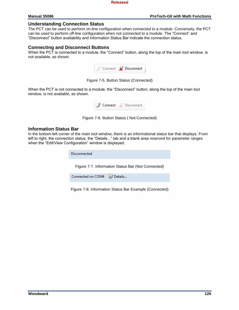
Manual 35086 ProTech-GII with Math Functions
Woodward 126
Understanding Connection Status The PCT can be used to perform on-line configuration when connected to a module. Conversely, the PCT can be used to perform off-line configuration when not connected to a module. The “Connect” and “Disconnect” button availability and Information Status Bar indicate the connection status.
Connecting and Disconnect Buttons When the PCT is connected to a module, the “Connect” button, along the top of the main tool window, is not available, as shown.
Figure 7-5. Button Status (Connected) When the PCT is not connected to a module, the “Disconnect” button, along the top of the main tool window, is not available, as shown.
Figure 7-6. Button Status ( Not Connected)
Information Status Bar In the bottom-left corner of the main tool window, there is an informational status bar that displays. From left to right, the connection status, the “Details...” tab and a blank area reserved for parameter ranges when the “Edit/View Configuration” window is displayed.
Figure 7-7. Information Status Bar (Not Connected)
Figure 7-8. Information Status Bar Example (Connected)
Released
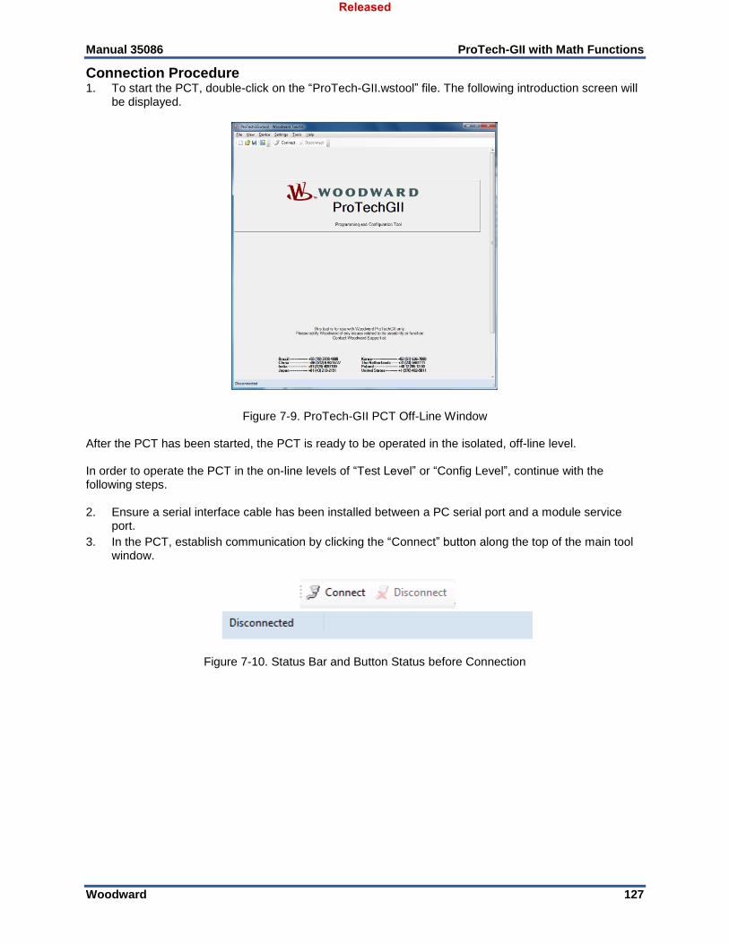
Manual 35086 ProTech-GII with Math Functions
Woodward 127
Connection Procedure 1. To start the PCT, double-click on the “ProTech-GII.wstool” file. The following introduction screen will
be displayed.
Figure 7-9. ProTech-GII PCT Off-Line Window
After the PCT has been started, the PCT is ready to be operated in the isolated, off-line level. In order to operate the PCT in the on-line levels of “Test Level” or “Config Level”, continue with the following steps. 2. Ensure a serial interface cable has been installed between a PC serial port and a module service
port.
3. In the PCT, establish communication by clicking the “Connect” button along the top of the main tool window.
Figure 7-10. Status Bar and Button Status before Connection
Released
Manual 35086 ProTech-GII with Math Functions
Woodward 128
4. The following pop-up window appears, prompting for a network selection.
Figure 7-11. PCT Connect Options Window 5. Select the communication port that the serial interface cable is connected to on the PC, then click the
“Connect” button at the bottom of the pop-up window.
6. Confirm the communication link has been established.
Figure 7-12. Status Bar and Button Status after Connection 7. When the communication link is established, the following pop-up window appears.
Figure 7-13. PCT Security Log-In Window 8. Set the “Security Level” to “Test Level” or “Config Level”, enter the associated password and click
the “Log In” button. Click the “Close” button if an on-line mode is not required.
9. If the communication link cannot be established, the PCT continues to attempt to establish the communication link until the “Disconnect” button along the top of the main window is clicked.
10. After communication has been established, the On-Line Menu is displayed. This window provides access to the ProTech-GII Logs. Additionally, this window can be used to monitor or change device configuration.
Released
Manual 35086 ProTech-GII with Math Functions
Woodward 129
A Note on Log Timestamps The time stamps in the logs are based on the internal clock at the time of the event. Time stamps are not changed when the internal clock time is modified (i.e. time/date is set).
Drop-Down Menu “Settings” The drop-down menu “Settings” is available regardless of connection status. While the options to create, modify, and compare Settings Files are always available, the options to load and retrieve Settings Files require on-line configuration. The following selections are available in the Drop-down Menu “Settings”:
Figure 7-14. Drop-Down Menu “Settings” When operating the PCT off line, the following selections can be used:
New from SID Specification Defaults...
Edit Settings File...
Compare Settings File Differences... When operating the PCT on line with “Test Level Password” permissions, the management of log files are active and the following selections can be used:
New from SID Specification Defaults....
Save from Device to File...
Edit Settings File...
Compare Settings File Differences... When operating the PCT on line with “Config Level Password” permissions, the management of log files are active and the following selections can be used:
New from SID Specification Defaults...
Save from Device to File...
Edit Settings File...
Load Settings File to Device...
Compare Settings file Differences...
Released
Manual 35086 ProTech-GII with Math Functions
Woodward 130
New from SID Specification Defaults Selection After selecting “New from SID Specification Defaults…”, the following sub-window appears with a list of Settings File specifications:
Figure 7-15. Prompt to Set Settings File Default Values Select the appropriate Settings File specification, compatible with your ProTech-GII Software P/N, as displayed on the front-panel “Monitor Module Information” screen (eg. “5418-7349 rev -"). The Settings Editor window, with default settings populated, is opened. At this point, parameters may be viewed and/or edited. For details on each configuration setting, refer to the Configuration Using the PCT Chapter. Upon completion of editing and/or viewing parameters, the Settings File must be saved by using the drop-down menu, “File”, followed by “Save As”. Settings Files are named with a “.wset” filename extension. Assign a file location and name, save the file on the PC and close the Settings Editor window.
Save from Device to File Selection To save a Settings File from a module, the PCT must be operated on line. After selecting “Save from Device to File...”, the following sub-window appears:
Figure 7-16. Prompt for Settings File to Modify The “Browse” button is used to select the location and name of the Settings File to which the parameters are to be saved. Settings Files are named with a “.wset” filename extension.
If the PCT is already operating on line, the transfer of the settings from the module starts immediately upon selecting the “Next >” button.
Released
Manual 35086 ProTech-GII with Math Functions
Woodward 131
If the PCT is operating off line, a prompt to connect will appear upon selecting the “Next >” button, the following pop-up screen appears. Select the appropriate network.
Figure 7-17. Prompt to Connect To connect, the appropriate selections for the desired on-line operating level should be made. Refer to the Connection Procedure Section and the PCT Levels of Operation Section earlier in this chapter for further detail. Once the PCT is operating on line, the transfer of the settings from the module starts immediately therein.
Edit Settings File Selection After selecting “Edit Settings File...”, the following sub-window appears to prompt for a name and location of a Settings File.
Figure 7-18. Prompt for Settings File to Edit Settings Files are named with a “.wset” filename extension. After selecting a Settings File, the Settings Editor window opens.
At this point, parameters may be viewed and/or edited. For details on each configuration setting, refer to the Configuration Using the PCT Chapter. Upon completion of editing and/or viewing parameters, the Settings File must be saved by using the drop-down menu, “File”, followed by “Save” or “Save As”. Settings Files are named with a “.wset” filename extension. Assign a file location and name, save the file on the PC and close the Settings Editor window.
Released
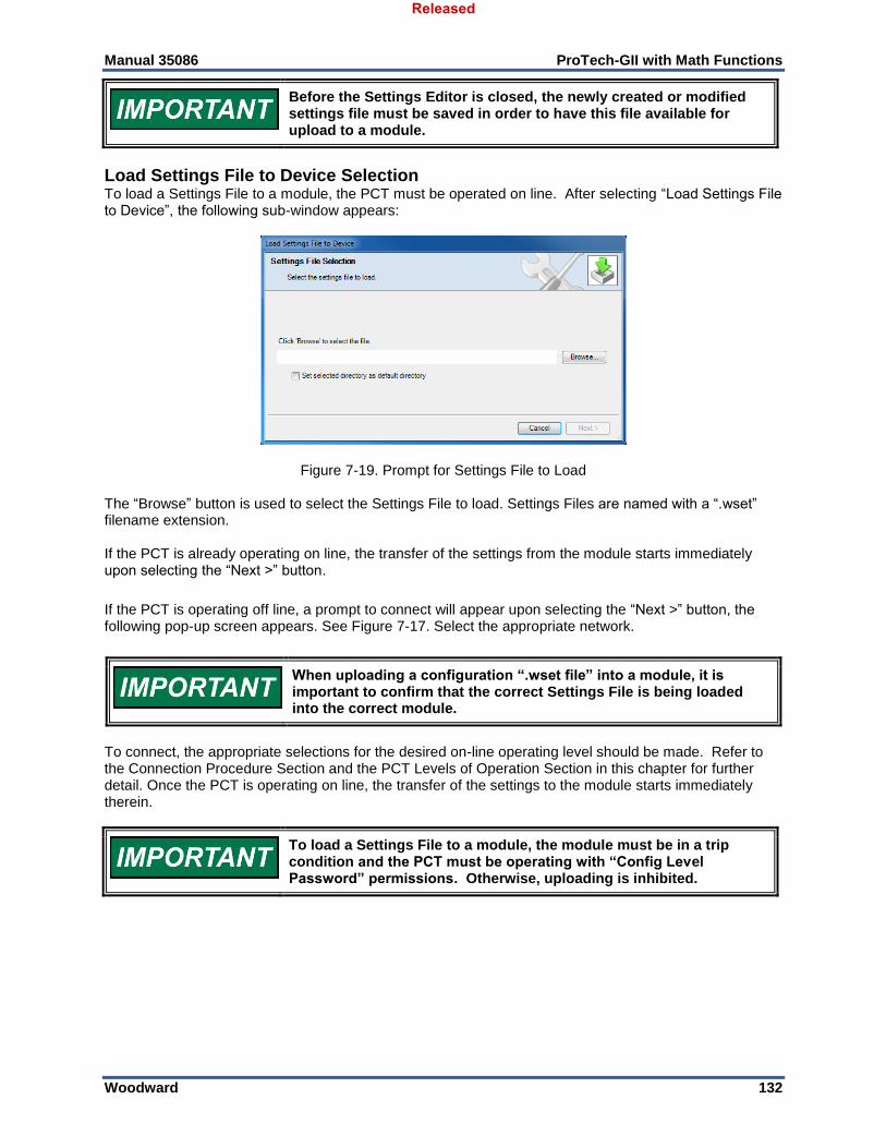
Manual 35086 ProTech-GII with Math Functions
Woodward 132
Before the Settings Editor is closed, the newly created or modified settings file must be saved in order to have this file available for upload to a module.
Load Settings File to Device Selection To load a Settings File to a module, the PCT must be operated on line. After selecting “Load Settings File to Device”, the following sub-window appears:
Figure 7-19. Prompt for Settings File to Load The “Browse” button is used to select the Settings File to load. Settings Files are named with a “.wset” filename extension. If the PCT is already operating on line, the transfer of the settings from the module starts immediately upon selecting the “Next >” button.
If the PCT is operating off line, a prompt to connect will appear upon selecting the “Next >” button, the following pop-up screen appears. See Figure 7-17. Select the appropriate network.
When uploading a configuration “.wset file” into a module, it is important to confirm that the correct Settings File is being loaded into the correct module.
To connect, the appropriate selections for the desired on-line operating level should be made. Refer to the Connection Procedure Section and the PCT Levels of Operation Section in this chapter for further detail. Once the PCT is operating on line, the transfer of the settings to the module starts immediately therein.
To load a Settings File to a module, the module must be in a trip condition and the PCT must be operating with “Config Level Password” permissions. Otherwise, uploading is inhibited.
Released
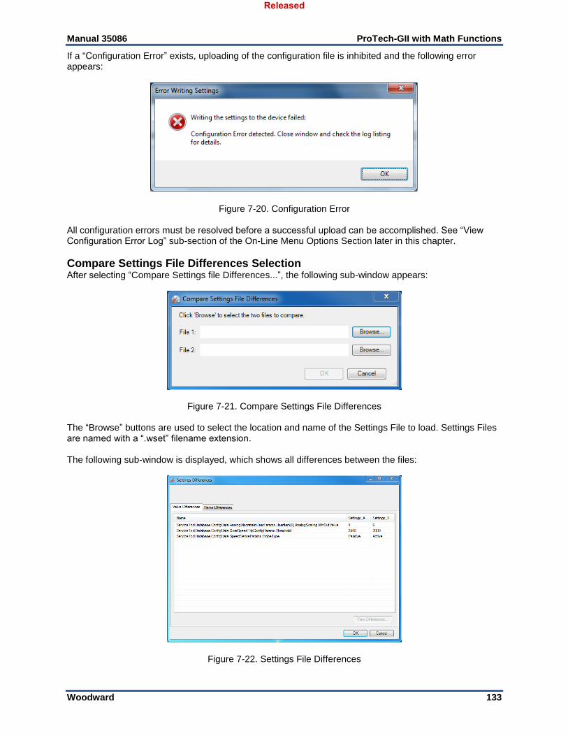
Manual 35086 ProTech-GII with Math Functions
Woodward 133
If a “Configuration Error” exists, uploading of the configuration file is inhibited and the following error appears:
Figure 7-20. Configuration Error All configuration errors must be resolved before a successful upload can be accomplished. See “View Configuration Error Log” sub-section of the On-Line Menu Options Section later in this chapter.
Compare Settings File Differences Selection After selecting “Compare Settings file Differences...”, the following sub-window appears:
Figure 7-21. Compare Settings File Differences The “Browse” buttons are used to select the location and name of the Settings File to load. Settings Files are named with a “.wset” filename extension. The following sub-window is displayed, which shows all differences between the files:
Figure 7-22. Settings File Differences
Released
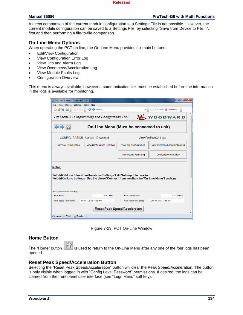
Manual 35086 ProTech-GII with Math Functions
Woodward 134
A direct comparison of the current module configuration to a Settings File is not possible. However, the current module configuration can be saved to a Settings File, by selecting “Save from Device to File...”, first and then performing a file-to-file comparison.
On-Line Menu Options When operating the PCT on line, the On-Line Menu provides six main buttons:
Edit/View Configuration
View Configuration Error Log
View Trip and Alarm Log
View Overspeed/Acceleration Log
View Module Faults Log
Configuration Overview This menu is always available, however a communication link must be established before the information in the logs is available for monitoring.
Figure 7-23. PCT On-Line Window
Home Button
The “Home” button is used to return to the On-Line Menu after any one of the four logs has been opened.
Reset Peak Speed/Acceleration Button Selecting the “Reset Peak Speed/Acceleration” button will clear the Peak Speed/Acceleration. The button is only visible when logged in with “Config Level Password” permissions. If desired, the logs can be cleared from the front panel user interface (see “Logs Menu” soft key).
Released
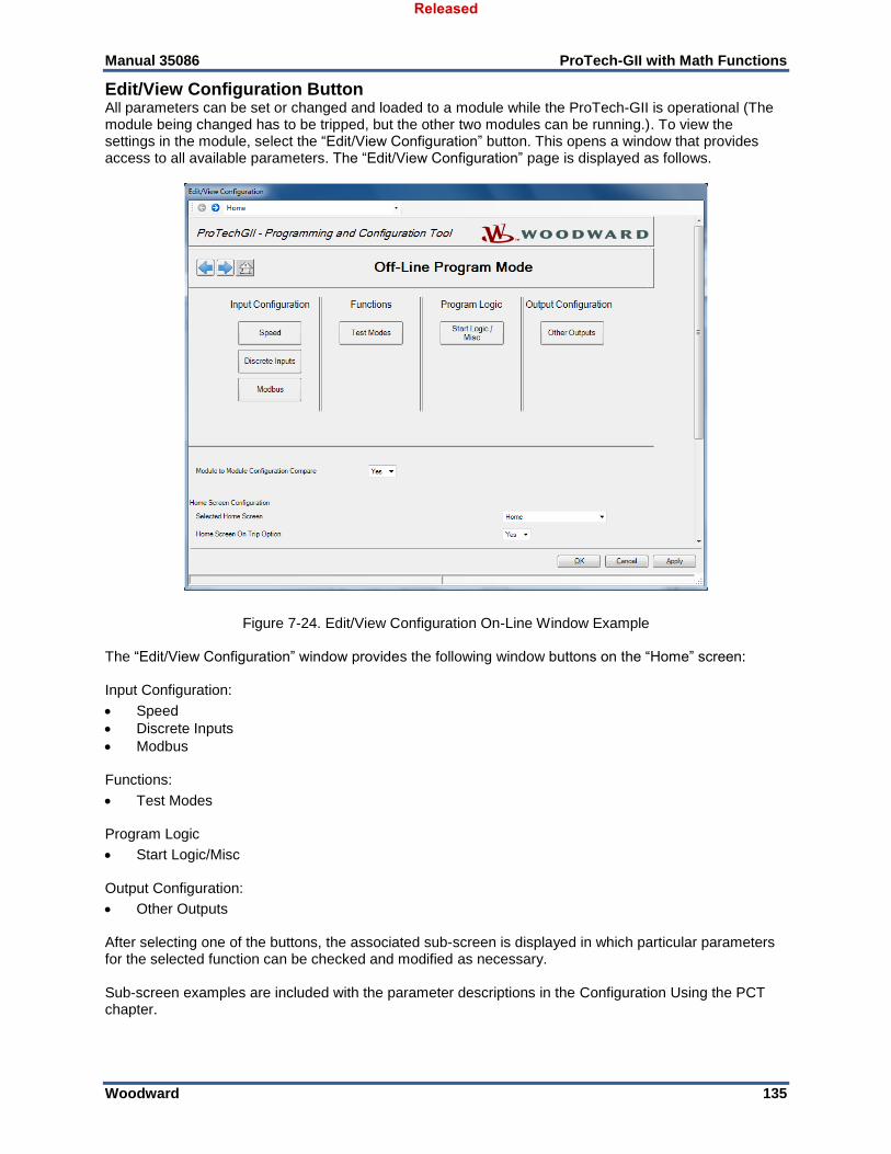
Manual 35086 ProTech-GII with Math Functions
Woodward 135
Edit/View Configuration Button All parameters can be set or changed and loaded to a module while the ProTech-GII is operational (The module being changed has to be tripped, but the other two modules can be running.). To view the settings in the module, select the “Edit/View Configuration” button. This opens a window that provides access to all available parameters. The “Edit/View Configuration” page is displayed as follows.
Figure 7-24. Edit/View Configuration On-Line Window Example The “Edit/View Configuration” window provides the following window buttons on the “Home” screen: Input Configuration:
Speed
Discrete Inputs
Modbus Functions:
Test Modes Program Logic
Start Logic/Misc Output Configuration:
Other Outputs After selecting one of the buttons, the associated sub-screen is displayed in which particular parameters for the selected function can be checked and modified as necessary. Sub-screen examples are included with the parameter descriptions in the Configuration Using the PCT chapter.
Released
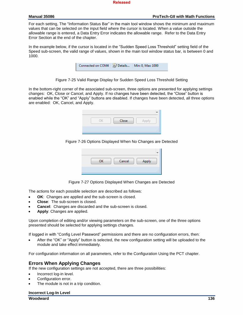
Manual 35086 ProTech-GII with Math Functions
Woodward 136
For each setting, The “Information Status Bar” in the main tool window shows the minimum and maximum values that can be selected on the input field where the cursor is located. When a value outside the allowable range is entered, a Data Entry Error indicates the allowable range. Refer to the Data Entry Error Section at the end of the chapter. In the example below, if the cursor is located in the “Sudden Speed Loss Threshold” setting field of the Speed sub-screen, the valid range of values, shown in the main tool window status bar, is between 0 and 1000.
Figure 7-25 Valid Range Display for Sudden Speed Loss Threshold Setting In the bottom-right corner of the associated sub-screen, three options are presented for applying settings changes: OK, Close or Cancel, and Apply. If no changes have been detected, the “Close” button is enabled while the “OK” and “Apply” buttons are disabled. If changes have been detected, all three options are enabled: OK, Cancel, and Apply.
Figure 7-26 Options Displayed When No Changes are Detected
Figure 7-27 Options Displayed When Changes are Detected The actions for each possible selection are described as follows:
OK: Changes are applied and the sub-screen is closed.
Close: The sub-screen is closed.
Cancel: Changes are discarded and the sub-screen is closed.
Apply: Changes are applied. Upon completion of editing and/or viewing parameters on the sub-screen, one of the three options presented should be selected for applying settings changes. If logged in with “Config Level Password” permissions and there are no configuration errors, then:
After the “OK” or “Apply” button is selected, the new configuration setting will be uploaded to the module and take effect immediately.
For configuration information on all parameters, refer to the Configuration Using the PCT chapter.
Errors When Applying Changes If the new configuration settings are not accepted, there are three possibilities:
Incorrect log-in level.
Configuration error.
The module is not in a trip condition. Incorrect Log-In Level
Released
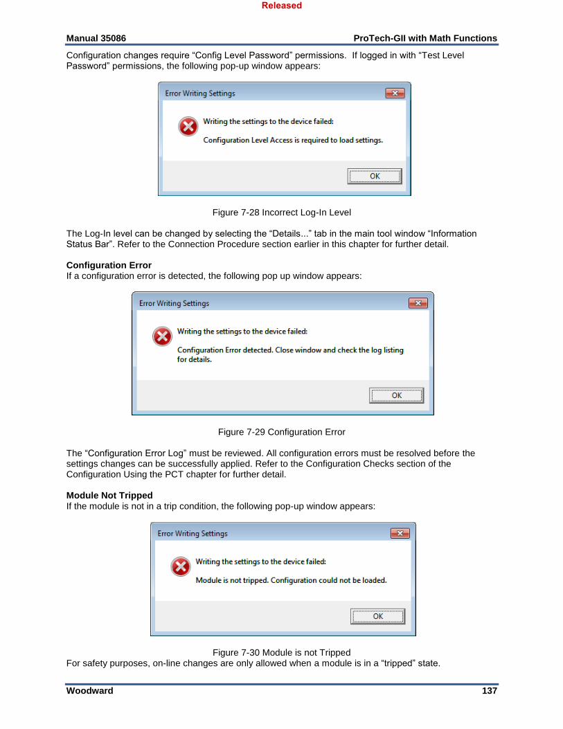
Manual 35086 ProTech-GII with Math Functions
Woodward 137
Configuration changes require “Config Level Password” permissions. If logged in with “Test Level Password” permissions, the following pop-up window appears:
Figure 7-28 Incorrect Log-In Level The Log-In level can be changed by selecting the “Details...” tab in the main tool window “Information Status Bar”. Refer to the Connection Procedure section earlier in this chapter for further detail. Configuration Error If a configuration error is detected, the following pop up window appears:
Figure 7-29 Configuration Error
The “Configuration Error Log” must be reviewed. All configuration errors must be resolved before the settings changes can be successfully applied. Refer to the Configuration Checks section of the Configuration Using the PCT chapter for further detail. Module Not Tripped If the module is not in a trip condition, the following pop-up window appears:
Figure 7-30 Module is not Tripped For safety purposes, on-line changes are only allowed when a module is in a “tripped” state.
Released
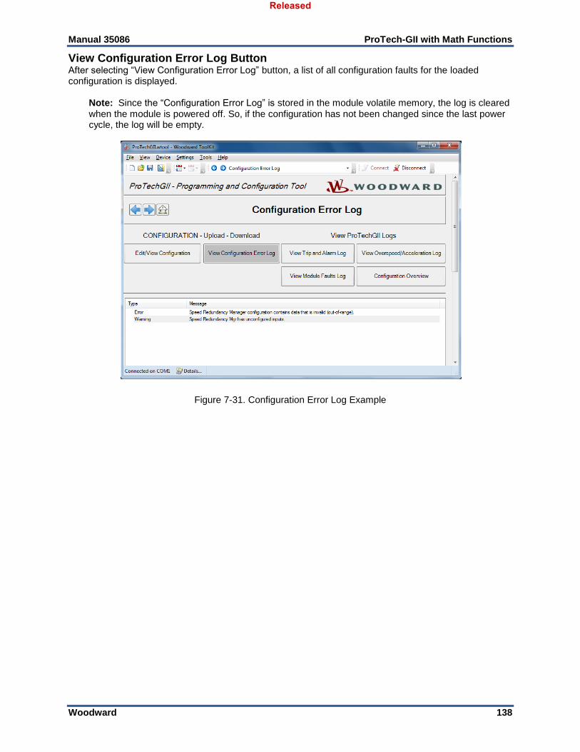
Manual 35086 ProTech-GII with Math Functions
Woodward 138
View Configuration Error Log Button After selecting “View Configuration Error Log” button, a list of all configuration faults for the loaded configuration is displayed.
Note: Since the “Configuration Error Log” is stored in the module volatile memory, the log is cleared when the module is powered off. So, if the configuration has not been changed since the last power cycle, the log will be empty.
Figure 7-31. Configuration Error Log Example
Released
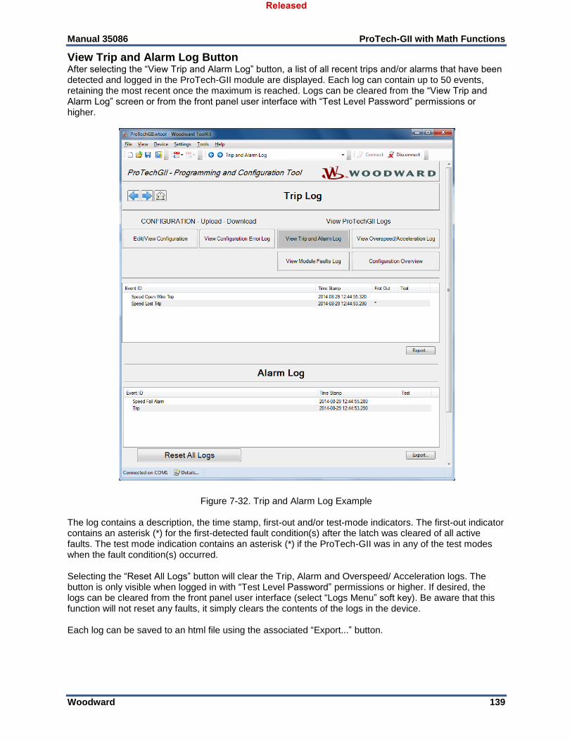
Manual 35086 ProTech-GII with Math Functions
Woodward 139
View Trip and Alarm Log Button After selecting the “View Trip and Alarm Log” button, a list of all recent trips and/or alarms that have been detected and logged in the ProTech-GII module are displayed. Each log can contain up to 50 events, retaining the most recent once the maximum is reached. Logs can be cleared from the “View Trip and Alarm Log” screen or from the front panel user interface with “Test Level Password” permissions or higher.
Figure 7-32. Trip and Alarm Log Example
The log contains a description, the time stamp, first-out and/or test-mode indicators. The first-out indicator contains an asterisk (*) for the first-detected fault condition(s) after the latch was cleared of all active faults. The test mode indication contains an asterisk (*) if the ProTech-GII was in any of the test modes when the fault condition(s) occurred. Selecting the “Reset All Logs” button will clear the Trip, Alarm and Overspeed/ Acceleration logs. The button is only visible when logged in with “Test Level Password” permissions or higher. If desired, the logs can be cleared from the front panel user interface (select “Logs Menu” soft key). Be aware that this function will not reset any faults, it simply clears the contents of the logs in the device. Each log can be saved to an html file using the associated “Export...” button.
Released
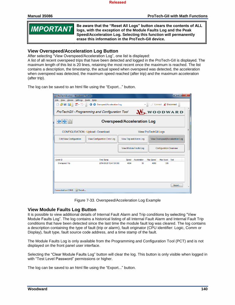
Manual 35086 ProTech-GII with Math Functions
Woodward 140
Be aware that the “Reset All Logs” button clears the contents of ALL logs, with the exception of the Module Faults Log and the Peak Speed/Acceleration Log. Selecting this function will permanently erase this information in the ProTech-GII device.
View Overspeed/Acceleration Log Button After selecting “View Overspeed/Acceleration Log”, one list is displayed: A list of all recent overspeed trips that have been detected and logged in the ProTech-GII is displayed. The maximum length of this list is 20 lines, retaining the most recent once the maximum is reached. The list contains a description, the timestamp, the actual speed when overspeed was detected, the acceleration when overspeed was detected, the maximum speed reached (after trip) and the maximum acceleration (after trip). The log can be saved to an html file using the “Export...” button.
Figure 7-33. Overspeed/Acceleration Log Example
View Module Faults Log Button It is possible to view additional details of Internal Fault Alarm and Trip conditions by selecting “View Module Faults Log”. The log contains a historical listing of all Internal Fault Alarm and Internal Fault Trip conditions that have been detected since the last time the module fault log was cleared. The log contains a description containing the type of fault (trip or alarm), fault originator (CPU identifier: Logic, Comm or Display), fault type, fault source code address, and a time stamp of the fault. The Module Faults Log is only available from the Programming and Configuration Tool (PCT) and is not displayed on the front panel user interface. Selecting the “Clear Module Faults Log” button will clear the log. This button is only visible when logged in with “Test Level Password” permissions or higher. The log can be saved to an html file using the “Export...” button.
Released
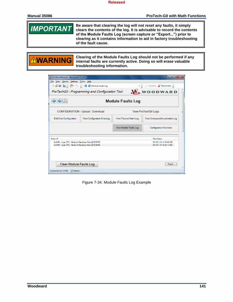
Manual 35086 ProTech-GII with Math Functions
Woodward 141
Be aware that clearing the log will not reset any faults, it simply clears the contents of the log. It is advisable to record the contents of the Module Faults Log (screen capture or “Export...”) prior to clearing as it contains information to aid in factory troubleshooting of the fault cause.
Clearing of the Module Faults Log should not be performed if any internal faults are currently active. Doing so will erase valuable troubleshooting information.
Figure 7-34. Module Faults Log Example
Released
Manual 35086 ProTech-GII with Math Functions
Woodward 142
Chapter 8. Configuration Using the PCT
Introduction This chapter provides details on the configuration screens and settings provided when using the Programming and Configuration Tool (PCT). Refer to Chapter 7 for general PCT information including setup, operation, on-line, and off-line configuration. Off-line configurations can be created or modified at any time. For safety purposes, on-line changes are only allowed when a module is in a “tripped” state.
Changing the configuration settings in the ProTech-GII is permissible only when the affected module is in a trip condition and with “Config Level Password” permission. Otherwise, configuration changes are inhibited.
Released
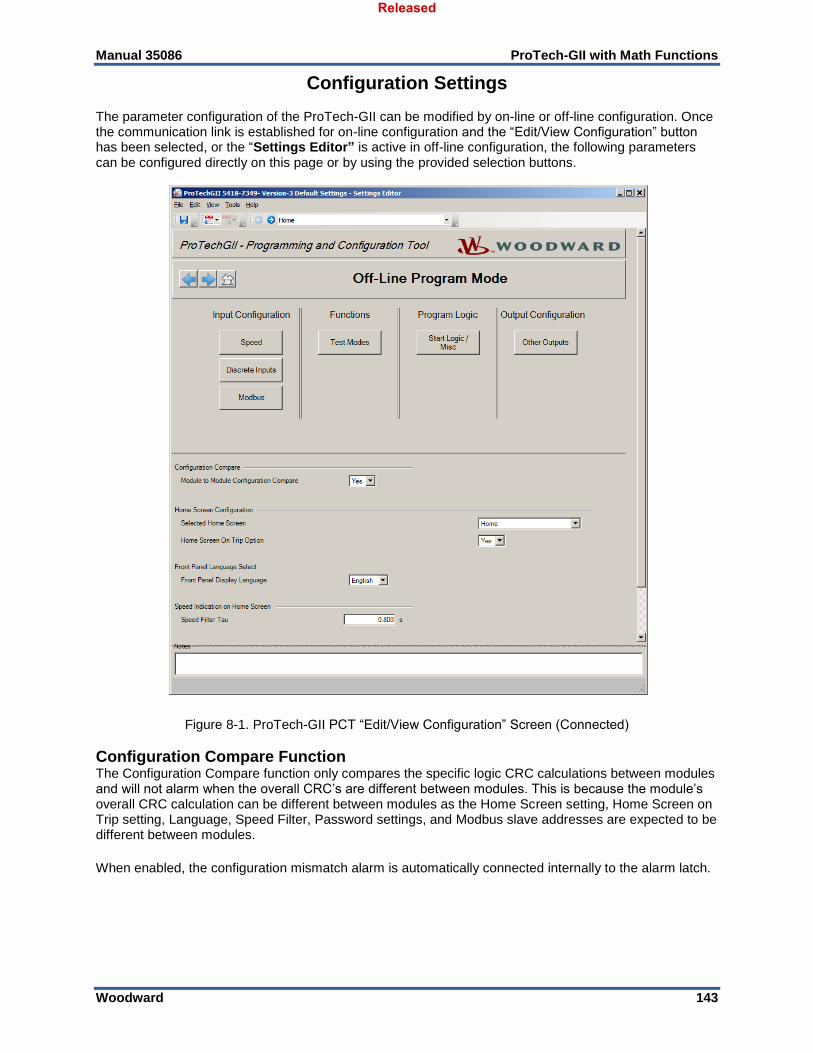
Manual 35086 ProTech-GII with Math Functions
Woodward 143
Configuration Settings The parameter configuration of the ProTech-GII can be modified by on-line or off-line configuration. Once the communication link is established for on-line configuration and the “Edit/View Configuration” button has been selected, or the “Settings Editor” is active in off-line configuration, the following parameters can be configured directly on this page or by using the provided selection buttons.
Figure 8-1. ProTech-GII PCT “Edit/View Configuration” Screen (Connected)
Configuration Compare Function The Configuration Compare function only compares the specific logic CRC calculations between modules and will not alarm when the overall CRC’s are different between modules. This is because the module’s overall CRC calculation can be different between modules as the Home Screen setting, Home Screen on Trip setting, Language, Speed Filter, Password settings, and Modbus slave addresses are expected to be different between modules.
When enabled, the configuration mismatch alarm is automatically connected internally to the alarm latch.
Released

Manual 35086 ProTech-GII with Math Functions
Woodward 144
Configuration Compare and Home Screen Configuration Settings The following parameters can be set:
Module to Module Configuration Compare: This setting is used to enable or disable the module-
to-module Configuration Compare alarm. When enabled, this function compares the configuration of the current module against the other two modules and generates an alarm if there is a difference. Valid values: Yes or No. Note: If each of the modules is deliberately configured differently to meet a specific application’s requirements, then this setting should be set to No.
Selected Home Screen: Set the screen to be displayed when the “Home” screen button is pressed. Valid values:
Table 8-1. Home Screen Valid Values
Home Monitor Accel Redundancy Manager
Monitor System Status
Monitor Summary Monitor Speed Fail Timer Monitor Module Information
Monitor Trip Latch Monitor Shared Start Overspeed/Acceleration Log
Monitor Alarm Latch Monitor Shared Reset Trip Log
Monitor Dedicated Discrete Inputs
Monitor Shared Speed Fail Override
Alarm Log
Monitor Speed Input Monitor Modbus Peak Speed/Acceleration Log.
Monitor Speed Redundancy Manager
Monitor/Set Date & Time
Home Screen On Trip Option: This setting is used to configure the action of the display upon sensing a trip condition. If configured “Yes” the module display will automatically change to the configured “Home Screen” upon sensing a trip condition. If configured “No”, the module display will not change upon a sensed trip condition. During system troubleshooting, it may be useful to temporarily set this setting to “No” to allow other screens to be viewed during a trip event. Valid values: Yes or No.
Front Panel Language Configuration
Language Select: Set the language. Valid values: English or Chinese.
Home screen speed filter
Speed Filter Tau (sec): Used to set the amount of filtering on the speed displayed on the Home screen. The speed displayed has a single-pole filter. This setting defines the tau value for this filter, in seconds. If an unfiltered value is desired, a setting of 4ms should be used (Input=Output). Note that this setting only affects the display on one screen (Home), active speed used within the device is not affected by this setting. Valid values: 0.004-10.
Remaining parameters can be set by selecting an applicable button. After selecting one of the buttons, a sub-screen is displayed in which particular parameters for the selected function can be checked and modified if necessary.
Released
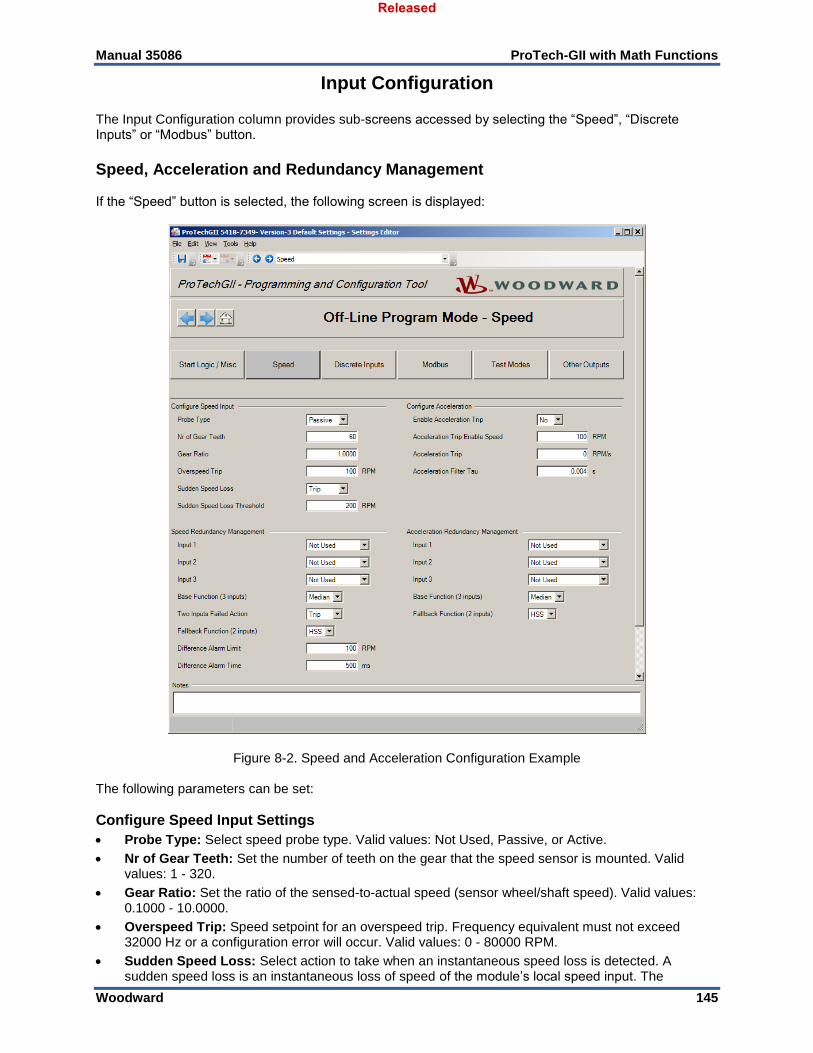
Manual 35086 ProTech-GII with Math Functions
Woodward 145
Input Configuration
The Input Configuration column provides sub-screens accessed by selecting the “Speed”, “Discrete Inputs” or “Modbus” button.
Speed, Acceleration and Redundancy Management If the “Speed” button is selected, the following screen is displayed:
Figure 8-2. Speed and Acceleration Configuration Example The following parameters can be set:
Configure Speed Input Settings
Probe Type: Select speed probe type. Valid values: Not Used, Passive, or Active.
Nr of Gear Teeth: Set the number of teeth on the gear that the speed sensor is mounted. Valid values: 1 - 320.
Gear Ratio: Set the ratio of the sensed-to-actual speed (sensor wheel/shaft speed). Valid values: 0.1000 - 10.0000.
Overspeed Trip: Speed setpoint for an overspeed trip. Frequency equivalent must not exceed 32000 Hz or a configuration error will occur. Valid values: 0 - 80000 RPM.
Sudden Speed Loss: Select action to take when an instantaneous speed loss is detected. A sudden speed loss is an instantaneous loss of speed of the module’s local speed input. The
Released
Manual 35086 ProTech-GII with Math Functions
Woodward 146
algorithm is: If the previous speed was above the Sudden Speed Loss Threshold and the current speed is “0” then a Sudden Speed Loss is annunciated, if used. Speed is updated on every zero crossing and “0” frequency is detected by no zero crossings on the speed input for 2 seconds. Valid values: Trip, Alarm, or Not Used.
Sudden Speed Loss is based on the local module speed input. If set to ‘Trip’, an instantaneous loss of the module’s speed input would result in a trip, regardless if a speed redundancy manager is used.
Sudden Speed Loss Threshold: Sudden Speed Loss is active above this speed threshold. Valid values: 1 - 1000 RPM.
Potential Impact of Speed Input Configuration Changes: When speed is used in any redundancy manager (Speed RM or Accel RM), changes to the speed settings (probe type, number of teeth, or gear ratio) will automatically force the signal to an ‘invalid’ state on all 3 modules (A,B,C). While ‘invalid’, that signal is removed from the voting selection and requires a reset command to restore it.
The speed sensing outputs are automatically connected internally to the speed signal and alarm/trip logic (overspeed, speed loss, and open wire). See also the Start Logic section for additional speed fail detection and diagnostics.
Speed Redundancy Management (RM) A speed redundancy manager is available which can be used to select speed from any input module (A, B, C). When configured, it automatically provides a voted scheme on up to three different speed signals. The output selection (voting) action is configurable, with predefined and selectable functionality for 3/2/1 signal outputs. For example, with three good/valid signals the action can be configured to use the median value, highest value, or lowest value. Another selection is provided for the speed selection with two good signals (highest, lowest). When only one good signal is available, the option is provided to either trip or continue to run using that remaining good speed signal. A trip is issued with no valid speed signal. When the speed redundancy manager is used, the following internal functions use the voted speed signal: Overspeed trip, Speed Fail Trip, and Speed Fail Timer. Local speed is always used for Speed Fail Alarm and Speed Lost (i.e. Sudden Speed Loss).
The speed redundancy manager provides the following outputs, which are automatically connected internally to the speed signal and alarm/trip logic.
Output: Analog signal. Speed selection is based on the number of valid/good inputs and the configured action. An Active Mode is provided on the front panel to indicate the currently active signal selection criteria (MEDIAN, HSS, or LSS).
Difference: Boolean signal. Indicates the value of the difference detection output. True when valid inputs exceed the difference threshold for longer than the difference delay time. False when the difference is less than the threshold for 3x the delay time.
Input 1-3 Invalid: Boolean signal (x3). Indicates the input is not valid and has been removed from the voting scheme. A reset is required to restore an invalid signal.
Speed RM Trip: Boolean signal. Set true when block issues a trip command. True with no valid inputs or with two failed inputs and configured to trip.
Released

Manual 35086 ProTech-GII with Math Functions
Woodward 147
Speed or Accel Input Invalid Indications An input becomes invalid if the shared signal is not available, which can be caused by a speed signal in test mode, by a changed configuration (speed input setting changed), by an improper configuration (speed not used), or by an inter-module communications issue. When an input is determined to be invalid, that input is not used by the redundancy manager. To restore an input that is no longer invalid, a reset is required. Note that an alarm latch connection is automatically (internally) provided for any speed inputs.
Speed Redundancy Management (RM) Settings
Input 1-3: Select which modules will be supplying a speed signal to the redundancy manager. Valid values: Module A Speed, Module B Speed, Module C Speed or Not Used.
Base Function (three inputs valid): Select the redundancy mode. Choices are Median, LSS (Low Signal Select), or HSS (High Signal Select). Valid values: Median, LSS or HSS
Two Inputs Failed Action: Selects the action when two speed signals have failed. Valid values: Trip or No Trip.
Fallback Function (two inputs valid): Select the redundancy mode when only two of three speed signals are valid. Valid values: HSS or LSS.
Difference Alarm Limit: The amount the speeds are allowed to differ before the Difference Alarm is set. Valid values: 0 - 80000 RPM.
Difference Alarm Time: The time the speed difference limit is allowed to exist before the Difference Alarm is set. Valid values: 4-10000 milliseconds.
If all inputs to the Speed Redundancy Management (Speed RM) are set to Not Used, then this function is not used. If at least one input is configured (a value other than Not Used), then the voted output is automatically used internally in the speed logic. If only one input is configured, the “Configuration Error Log” will indicate a “Configuration Warning”. The configuration is allowed, but this warning is intended to draw attention and make sure this is intended.
Configure Acceleration Settings
Enable Acceleration Trip: Set to yes to use this function. Valid values: Yes or No.
Acceleration Trip Enable Speed: Speed setpoint at which over-acceleration trip is active. Below this speed, the acceleration trip is not active. Valid values: 0 - 80000 RPM.
Acceleration Trip: Over-acceleration trip setpoint in RPM/second. Valid values: 0 - 25000 RPM/s.
Acceleration Filter Tau (sec): The acceleration signal is filtered using a single-pole filter. This input defines the tau value for this filter, in seconds. If an unfiltered value is desired, a setting of 2ms should be used (Input=Output). Valid values: 0.002-10.
The acceleration sensing outputs are automatically connected internally to the alarm/trip logic
Acceleration Redundancy Management An acceleration redundancy manager is available which can be used to select acceleration from any input module (A, B, or C). When configured, it automatically provides a voted scheme on up to three different signals. The output selection (voting) action is configurable, with predefined and selectable functionality for 3/2/1 signal outputs. For example, with three good/valid signals, the action can be configured to use the median value, highest value, or lowest value. Another selection is provided for the selection with two good signals (highest, lowest). When only one good signal is available, that remaining good signal is used. The acceleration redundancy manager provides the following outputs. The Output is automatically used for the over-acceleration trip, when used. When a speed redundancy manager is used, the ‘Invalid’ indications from that function block would typically provide failure indications (since acceleration is based on speed).
Output: Analog signal. Acceleration selection is based on the number of valid/good inputs and the configured selection criteria.
Input 1-3 Invalid: Boolean signal (x3). Indicates the input is not valid and has been removed from the voting scheme. A reset is required to restore an invalid signal.
Released
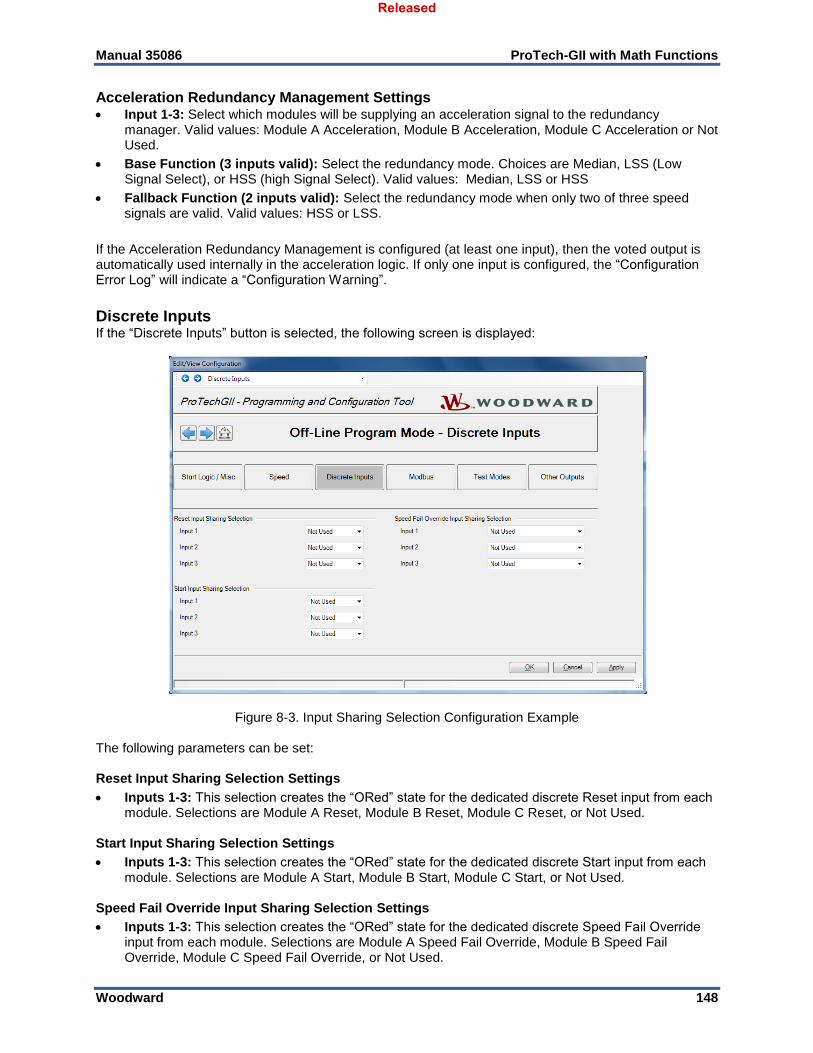
Manual 35086 ProTech-GII with Math Functions
Woodward 148
Acceleration Redundancy Management Settings Input 1-3: Select which modules will be supplying an acceleration signal to the redundancy
manager. Valid values: Module A Acceleration, Module B Acceleration, Module C Acceleration or Not Used.
Base Function (3 inputs valid): Select the redundancy mode. Choices are Median, LSS (Low Signal Select), or HSS (high Signal Select). Valid values: Median, LSS or HSS
Fallback Function (2 inputs valid): Select the redundancy mode when only two of three speed signals are valid. Valid values: HSS or LSS.
If the Acceleration Redundancy Management is configured (at least one input), then the voted output is automatically used internally in the acceleration logic. If only one input is configured, the “Configuration Error Log” will indicate a “Configuration Warning”.
Discrete Inputs If the “Discrete Inputs” button is selected, the following screen is displayed:
Figure 8-3. Input Sharing Selection Configuration Example The following parameters can be set: Reset Input Sharing Selection Settings
Inputs 1-3: This selection creates the “ORed” state for the dedicated discrete Reset input from each module. Selections are Module A Reset, Module B Reset, Module C Reset, or Not Used.
Start Input Sharing Selection Settings
Inputs 1-3: This selection creates the “ORed” state for the dedicated discrete Start input from each module. Selections are Module A Start, Module B Start, Module C Start, or Not Used.
Speed Fail Override Input Sharing Selection Settings
Inputs 1-3: This selection creates the “ORed” state for the dedicated discrete Speed Fail Override input from each module. Selections are Module A Speed Fail Override, Module B Speed Fail Override, Module C Speed Fail Override, or Not Used.
Released
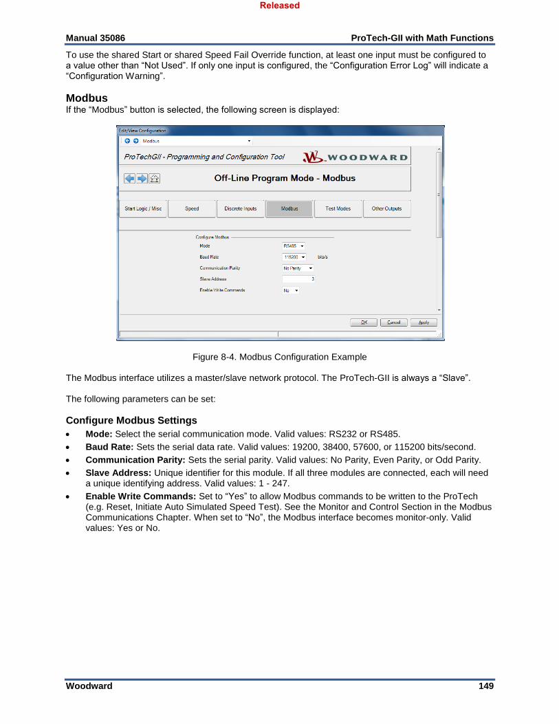
Manual 35086 ProTech-GII with Math Functions
Woodward 149
To use the shared Start or shared Speed Fail Override function, at least one input must be configured to a value other than “Not Used”. If only one input is configured, the “Configuration Error Log” will indicate a “Configuration Warning”.
Modbus If the “Modbus” button is selected, the following screen is displayed:
Figure 8-4. Modbus Configuration Example The Modbus interface utilizes a master/slave network protocol. The ProTech-GII is always a “Slave”. The following parameters can be set:
Configure Modbus Settings
Mode: Select the serial communication mode. Valid values: RS232 or RS485.
Baud Rate: Sets the serial data rate. Valid values: 19200, 38400, 57600, or 115200 bits/second.
Communication Parity: Sets the serial parity. Valid values: No Parity, Even Parity, or Odd Parity.
Slave Address: Unique identifier for this module. If all three modules are connected, each will need a unique identifying address. Valid values: 1 - 247.
Enable Write Commands: Set to “Yes” to allow Modbus commands to be written to the ProTech (e.g. Reset, Initiate Auto Simulated Speed Test). See the Monitor and Control Section in the Modbus Communications Chapter. When set to “No”, the Modbus interface becomes monitor-only. Valid values: Yes or No.
Released
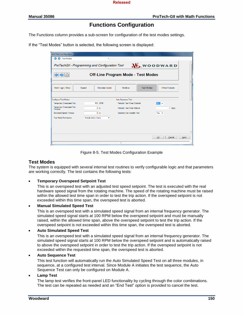
Manual 35086 ProTech-GII with Math Functions
Woodward 150
Functions Configuration The Functions column provides a sub-screen for configuration of the test modes settings.
If the “Test Modes” button is selected, the following screen is displayed:
Figure 8-5. Test Modes Configuration Example
Test Modes The system is equipped with several internal test routines to verify configurable logic and that parameters are working correctly. The test contains the following tests:
Temporary Overspeed Setpoint Test
This is an overspeed test with an adjusted test speed setpoint. The test is executed with the real hardware speed signal from the rotating machine. The speed of the rotating machine must be raised within the allowed test time span in order to test the trip action. If the overspeed setpoint is not exceeded within this time span, the overspeed test is aborted.
Manual Simulated Speed Test
This is an overspeed test with a simulated speed signal from an internal frequency generator. The simulated speed signal starts at 100 RPM below the overspeed setpoint and must be manually raised, within the allowed time span, above the overspeed setpoint to test the trip action. If the overspeed setpoint is not exceeded within this time span, the overspeed test is aborted.
Auto Simulated Speed Test
This is an overspeed test with a simulated speed signal from an internal frequency generator. The simulated speed signal starts at 100 RPM below the overspeed setpoint and is automatically raised to above the overspeed setpoint in order to test the trip action. If the overspeed setpoint is not exceeded within the requested time span, the overspeed test is aborted.
Auto Sequence Test
This test function will automatically run the Auto Simulated Speed Test on all three modules, in sequence, at a configured test interval. Since Module A initiates the test sequence, the Auto Sequence Test can only be configured on Module A.
Lamp Test
The lamp test verifies the front-panel LED functionality by cycling through the color combinations. The test can be repeated as needed and an “End Test” option is provided to cancel the test.
Released
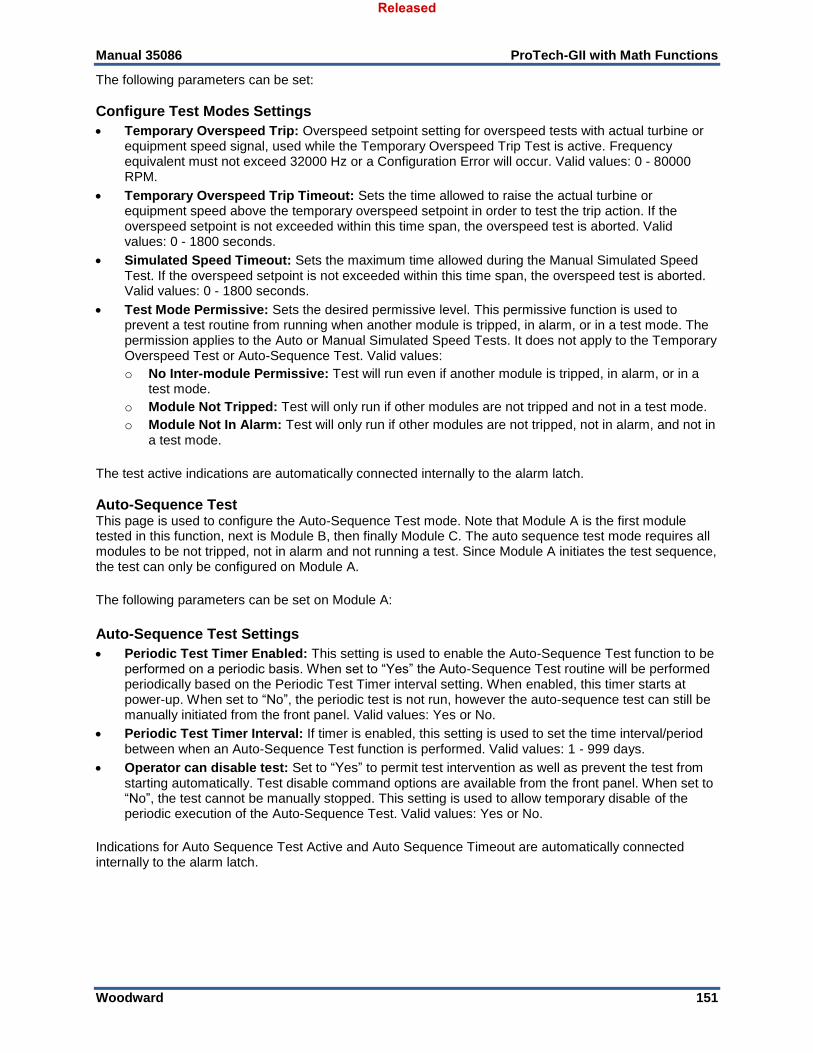
Manual 35086 ProTech-GII with Math Functions
Woodward 151
The following parameters can be set:
Configure Test Modes Settings
Temporary Overspeed Trip: Overspeed setpoint setting for overspeed tests with actual turbine or equipment speed signal, used while the Temporary Overspeed Trip Test is active. Frequency equivalent must not exceed 32000 Hz or a Configuration Error will occur. Valid values: 0 - 80000 RPM.
Temporary Overspeed Trip Timeout: Sets the time allowed to raise the actual turbine or equipment speed above the temporary overspeed setpoint in order to test the trip action. If the overspeed setpoint is not exceeded within this time span, the overspeed test is aborted. Valid values: 0 - 1800 seconds.
Simulated Speed Timeout: Sets the maximum time allowed during the Manual Simulated Speed Test. If the overspeed setpoint is not exceeded within this time span, the overspeed test is aborted. Valid values: 0 - 1800 seconds.
Test Mode Permissive: Sets the desired permissive level. This permissive function is used to prevent a test routine from running when another module is tripped, in alarm, or in a test mode. The permission applies to the Auto or Manual Simulated Speed Tests. It does not apply to the Temporary Overspeed Test or Auto-Sequence Test. Valid values:
o No Inter-module Permissive: Test will run even if another module is tripped, in alarm, or in a test mode.
o Module Not Tripped: Test will only run if other modules are not tripped and not in a test mode.
o Module Not In Alarm: Test will only run if other modules are not tripped, not in alarm, and not in a test mode.
The test active indications are automatically connected internally to the alarm latch.
Auto-Sequence Test This page is used to configure the Auto-Sequence Test mode. Note that Module A is the first module tested in this function, next is Module B, then finally Module C. The auto sequence test mode requires all modules to be not tripped, not in alarm and not running a test. Since Module A initiates the test sequence, the test can only be configured on Module A.
The following parameters can be set on Module A:
Auto-Sequence Test Settings
Periodic Test Timer Enabled: This setting is used to enable the Auto-Sequence Test function to be performed on a periodic basis. When set to “Yes” the Auto-Sequence Test routine will be performed periodically based on the Periodic Test Timer interval setting. When enabled, this timer starts at power-up. When set to “No”, the periodic test is not run, however the auto-sequence test can still be manually initiated from the front panel. Valid values: Yes or No.
Periodic Test Timer Interval: If timer is enabled, this setting is used to set the time interval/period between when an Auto-Sequence Test function is performed. Valid values: 1 - 999 days.
Operator can disable test: Set to “Yes” to permit test intervention as well as prevent the test from starting automatically. Test disable command options are available from the front panel. When set to “No”, the test cannot be manually stopped. This setting is used to allow temporary disable of the periodic execution of the Auto-Sequence Test. Valid values: Yes or No.
Indications for Auto Sequence Test Active and Auto Sequence Timeout are automatically connected internally to the alarm latch.
Released
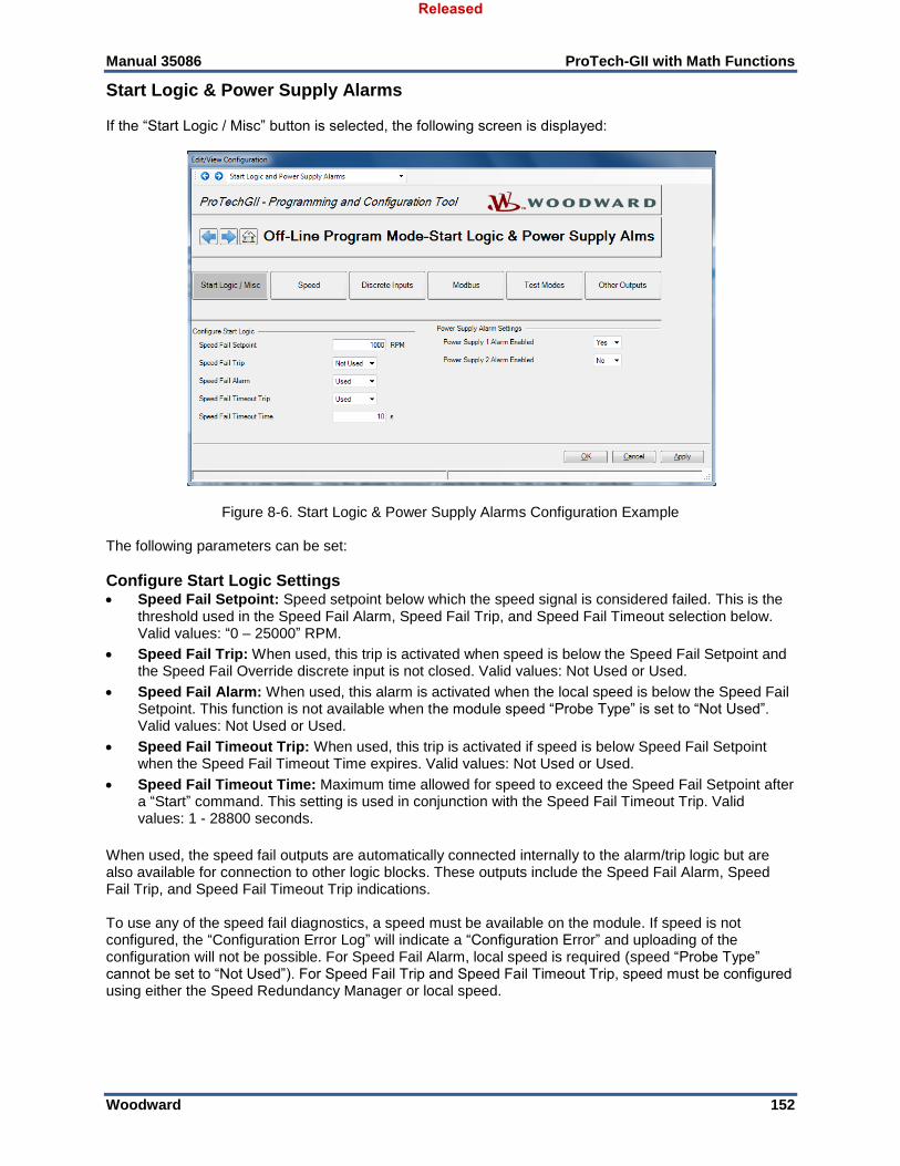
Manual 35086 ProTech-GII with Math Functions
Woodward 152
Start Logic & Power Supply Alarms If the “Start Logic / Misc” button is selected, the following screen is displayed:
Figure 8-6. Start Logic & Power Supply Alarms Configuration Example The following parameters can be set:
Configure Start Logic Settings Speed Fail Setpoint: Speed setpoint below which the speed signal is considered failed. This is the
threshold used in the Speed Fail Alarm, Speed Fail Trip, and Speed Fail Timeout selection below. Valid values: “0 – 25000” RPM.
Speed Fail Trip: When used, this trip is activated when speed is below the Speed Fail Setpoint and the Speed Fail Override discrete input is not closed. Valid values: Not Used or Used.
Speed Fail Alarm: When used, this alarm is activated when the local speed is below the Speed Fail Setpoint. This function is not available when the module speed “Probe Type” is set to “Not Used”. Valid values: Not Used or Used.
Speed Fail Timeout Trip: When used, this trip is activated if speed is below Speed Fail Setpoint when the Speed Fail Timeout Time expires. Valid values: Not Used or Used.
Speed Fail Timeout Time: Maximum time allowed for speed to exceed the Speed Fail Setpoint after a “Start” command. This setting is used in conjunction with the Speed Fail Timeout Trip. Valid values: 1 - 28800 seconds.
When used, the speed fail outputs are automatically connected internally to the alarm/trip logic but are also available for connection to other logic blocks. These outputs include the Speed Fail Alarm, Speed Fail Trip, and Speed Fail Timeout Trip indications. To use any of the speed fail diagnostics, a speed must be available on the module. If speed is not configured, the “Configuration Error Log” will indicate a “Configuration Error” and uploading of the configuration will not be possible. For Speed Fail Alarm, local speed is required (speed “Probe Type” cannot be set to “Not Used”). For Speed Fail Trip and Speed Fail Timeout Trip, speed must be configured using either the Speed Redundancy Manager or local speed.
Released
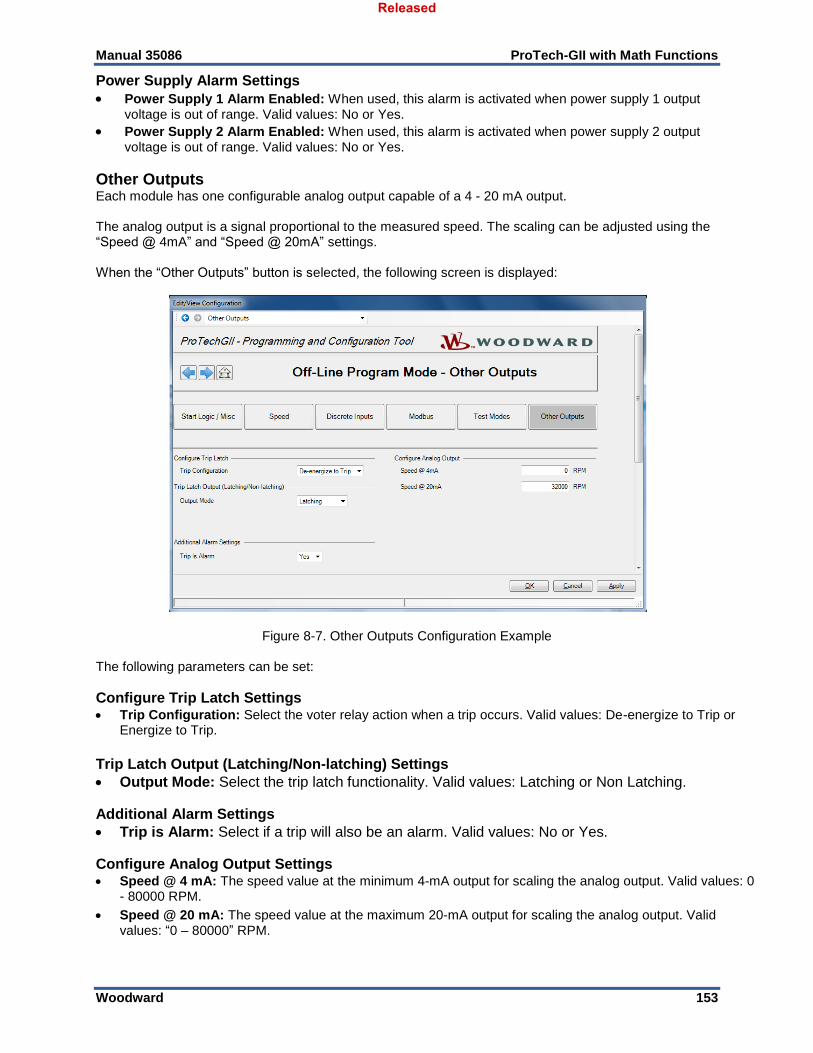
Manual 35086 ProTech-GII with Math Functions
Woodward 153
Power Supply Alarm Settings
Power Supply 1 Alarm Enabled: When used, this alarm is activated when power supply 1 output voltage is out of range. Valid values: No or Yes.
Power Supply 2 Alarm Enabled: When used, this alarm is activated when power supply 2 output voltage is out of range. Valid values: No or Yes.
Other Outputs Each module has one configurable analog output capable of a 4 - 20 mA output. The analog output is a signal proportional to the measured speed. The scaling can be adjusted using the “Speed @ 4mA” and “Speed @ 20mA” settings. When the “Other Outputs” button is selected, the following screen is displayed:
Figure 8-7. Other Outputs Configuration Example The following parameters can be set:
Configure Trip Latch Settings Trip Configuration: Select the voter relay action when a trip occurs. Valid values: De-energize to Trip or
Energize to Trip.
Trip Latch Output (Latching/Non-latching) Settings
Output Mode: Select the trip latch functionality. Valid values: Latching or Non Latching.
Additional Alarm Settings
Trip is Alarm: Select if a trip will also be an alarm. Valid values: No or Yes.
Configure Analog Output Settings Speed @ 4 mA: The speed value at the minimum 4-mA output for scaling the analog output. Valid values: 0
- 80000 RPM.
Speed @ 20 mA: The speed value at the maximum 20-mA output for scaling the analog output. Valid values: “0 – 80000” RPM.
Released
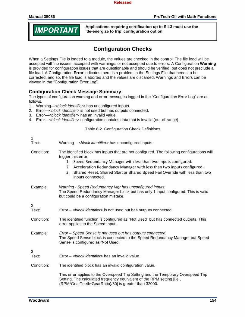
Manual 35086 ProTech-GII with Math Functions
Woodward 154
Applications requiring certification up to SIL3 must use the ‘de-energize to trip’ configuration option.
Configuration Checks When a Settings File is loaded to a module, the values are checked in the control. The file load will be accepted with no issues, accepted with warnings, or not accepted due to errors. A Configuration Warning is provided for configuration issues that are questionable and should be verified, but does not preclude a file load. A Configuration Error indicates there is a problem in the Settings File that needs to be corrected, and so, the file load is aborted and the values are discarded. Warnings and Errors can be viewed in the “Configuration Error Log”.
Configuration Check Message Summary The types of configuration warning and error messages logged in the “Configuration Error Log” are as follows. 1. Warning—<block identifier> has unconfigured inputs. 2. Error—<block identifier> is not used but has outputs connected. 3. Error—<block identifier> has an invalid value. 4. Error—<block identifier> configuration contains data that is invalid (out-of-range).
Table 8-2. Configuration Check Definitions 1 Text: Warning – <block identifier> has unconfigured inputs.
Condition: The identified block has inputs that are not configured. The following configurations will
trigger this error:
1. Speed Redundancy Manager with less than two inputs configured. 2. Acceleration Redundancy Manager with less than two inputs configured. 3. Shared Reset, Shared Start or Shared Speed Fail Override with less than two
inputs connected.
Example: Warning - Speed Redundancy Mgr has unconfigured inputs. The Speed Redundancy Manager block but has only 1 input configured. This is valid but could be a configuration mistake.
2 Text: Error – <block identifier> is not used but has outputs connected.
Condition: The identified function is configured as “Not Used” but has connected outputs. This
error applies to the Speed Input.
Example: Error – Speed Sense is not used but has outputs connected.
The Speed Sense block is connected to the Speed Redundancy Manager but Speed Sense is configured as ‘Not Used’.
3 Text: Error – <block identifier> has an invalid value.
Condition: The identified block has an invalid configuration value.
This error applies to the Overspeed Trip Setting and the Temporary Overspeed Trip Setting. The calculated frequency equivalent of the RPM setting [i.e., (RPM*GearTeeth*GearRatio)/60] is greater than 32000.
Released
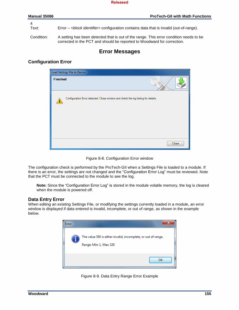
Manual 35086 ProTech-GII with Math Functions
Woodward 155
Error Messages
Configuration Error
Figure 8-8. Configuration Error window The configuration check is performed by the ProTech-GII when a Settings File is loaded to a module. If there is an error, the settings are not changed and the “Configuration Error Log” must be reviewed. Note that the PCT must be connected to the module to see the log.
Note: Since the “Configuration Error Log” is stored in the module volatile memory, the log is cleared when the module is powered off.
Data Entry Error When editing an existing Settings File, or modifying the settings currently loaded in a module, an error window is displayed if data entered is invalid, incomplete, or out of range, as shown in the example below.
Figure 8-9. Data Entry Range Error Example
4 Text: Error – <block identifier> configuration contains data that is invalid (out-of-range).
Condition: A setting has been detected that is out of the range. This error condition needs to be
corrected in the PCT and should be reported to Woodward for correction.
Released

Manual 35086 ProTech-GII with Math Functions
Woodward 156
Chapter 9. Modbus Communications
Introduction The ProTech-GII can communicate with plant-distributed control systems and/or CRT based operator control panels through three Modbus communication ports (one port per module). Each of the three modules (A, B, & C) has a serial port for Modbus communications. These ports support RS-232 or RS-485 communications using a standard Remote Terminal Unit (RTU) Modbus transmission protocol. The Modbus interface utilizes a master/slave protocol. This protocol determines how a communication network’s master and slave devices establish and break contact, how a sender is identified, how messages are exchanged, and how errors are detected. Each module Modbus port is fully isolated from those of the other modules and provides all module-based information (Input/Output channel state information, alarm and trip relay information, first-out indication, etc.). However, it can also be used to sense the following information from the other two modules:
Sensed Speed – other two modules
Acceleration – other two modules
Alarm Latch State – other two modules
Trip Latch State – other two modules
Note: Modbus-based write commands (for test purposes) can only be given to the module via the module Modbus communication port.
Table 9-1. Modbus Communication Port Specifications
Number of Ports: 1
Comm Type: RS-232/RS-485, user selectable
Termination Resistor: RS-485 on board, terminal block selectable
Isolation: 500 Vac from output to chassis and output to all other circuits
Signal Cable Length: Must be limited to 1500 ft / 305 m RS-485 (low capacitance 16 AWG / 1.3 mm²), 50 ft / 15 m RS-232
Monitor Only Each Modbus communication port is designed to continually output all Boolean Read and Analog Read information and can be configured to accept or ignore “write” commands, depending on the specific application requirements. Ignoring “write” commands allows the ProTech-GII to be monitored but not controlled from an external device. If the ProTech-GII module “Enable Write Commands” Modbus setting is configured “No”, the respective ProTech-GII module will not accept “write” commands from an external master device (DCS, etc.). For security purposes, the option to ignore “write” commands can only be enabled or disabled with “Config Level Password” permissions.
Monitor and Control If the ProTech-GII module “Enable Write Commands” Modbus setting is configured to “Yes”, the respective ProTech-GII module will accept “write” commands from an external master device (DCS, etc.). This allows a Modbus-compatible device to monitor all read registers and issue “Reset” and “Start/Abort Test Routines” commands only. Modbus communication ports are independent of each other and can be used simultaneously. To ensure that a Modbus-based command to trigger a module test is valid, an Initiate Test command followed by a Confirm Test command must be received to initiate a test routine. The Confirm Test
Released
Manual 35086 ProTech-GII with Math Functions
Woodward 157
command must be received within 10 seconds of the Initiate Test command; otherwise, the sequence must be performed again. The ProTech-GII is designed to allow only one module to be tested at a time. Thus, a module will only accept an Initiate Test command and perform the requested test if all three modules are healthy, not tripped, not in a test mode, and optionally not in alarm.
Modbus Interface Each ProTech-GII module is designed to function as a slave device on a Modbus network using the industry-standard Modbus RTU (Remote Terminal Unit) transmission protocol. For more information on Modbus networks and the RTU transmission protocol, refer to Modbus Protocol Reference Guide PI–MBUS–300 Rev. J. A Modbus function code tells the addressed slaves what function to perform. The following table lists the function codes supported by the ProTech-GII:
Table 9-2. Supported Modbus Function Codes
Code Definition Reference Address
02 Boolean Read (Read Input Status) (Status of Alarms/Shutdowns, Discrete input/outputs)
1XXXX
04 Analog Read (Read Input Registers) (Speed, Acceleration, etc.)
3XXXX
05 Boolean Write (Force Single Coil) (Reset and Test Initiate Commands)
0XXXX
08 Loopback Diagnostic Test – Diagnostic code 0 only As a slave Modbus device, the ProTech-GII is not responsible to sense or annunciate Modbus link communication errors. However, for troubleshooting purposes, the ProTech-GII does display a “Modbus Link Status” on the front-panel “Monitor Modbus” screen of the affected module. A “Link Error” message will be displayed if a Modbus transaction request is not received within a five-second time-out period. This error message is automatically cleared when Modbus communications are re-established.
Port Adjustments Before the ProTech-GII can communicate with the master device, the communication parameters must be verified to match the master device protocol settings. For security purposes, these parameters can only be set with “Config Level Password” permissions.
Table 9-3. Modbus Serial Communication Port Settings
Parameter Range
Mode: RS-232 or RS-485 Baud Rate: 19200 to 115200
Comm Parity: NONE, ODD or EVEN Slave Address: 1 - 247
Enable Write Commands: Yes or No
ProTech-GII Parameter Addresses Each available read or write parameter has a unique Modbus address. A complete list of the available parameters and their addresses is located at the end of this chapter. This list consists of Boolean Write, Boolean Read, and Analog Read parameters. Analog Write parameters are not used nor available with this device. Reserved address ranges can be read, but they are undefined for ProTech-GII.
Released

Manual 35086 ProTech-GII with Math Functions
Woodward 158
All values that can be addressed by the Modbus protocol are considered to be discrete or numeric. The discrete values are a 1-bit binary value, and the numeric values are 16-bit values. Discrete values are sometimes referred to as coils or digitals, and numeric values are referred to as registers or analogs. Numeric values can range from –32767 to +32767 if interpreted as a signed value or from “0 to 65535” if interpreted as an unsigned value. Since the Modbus protocol can only handle integers, values that require a value outside of the allowable range are multiplied by a constant, or pre-scaled, before being sent by the ProTech-GII module.
Boolean Writes (Code 05) Because Boolean Write commands are rising edge-triggered, a write command may need to be issue first with the discrete value set to “0” and again with the discrete value set to “1”. No password is required when issuing a command via the Modbus interface but the module must be configured to accept Write Commands. While selected discretes are described below, the full list available to write are listed in Table 8-3. Initiating the Auto Simulated Speed Test The Auto Simulated Speed Test can be started by first sending an Initiate Auto Simulated Speed Test command, followed by a Confirm Auto Simulated Speed Test command. If the confirm command is not sent within 10 seconds after the Initiate command is sent, the test will not be started. The intent of the confirmation is to prevent an erroneous signal from initiating a test. The test will not start if the Abort command is true. Refer to the “Test Routines” Section of the “Functionality” Chapter for further test detail. Initiate Auto Simulated Speed Test (0:0102) This discrete provides the first command of a two-command sequence to initiate the Auto Simulated Speed Test. This command must be followed by a Confirm command within 10 seconds or the test will not be started. This command must be maintained true until the Confirm command is received. Additionally the Abort command must be false or the test will not start. Confirm Auto Simulated Speed Test (0:0101) This discrete provides the second command of a two-command sequence to confirm initiation of the Auto Simulated Speed Test. This command must be preceded by an Initiate command (maintained true) in the immediately prior 10 seconds or the test will not be started. Abort Auto Simulated Speed Test (0:0103) This discrete provides the command to abort the Auto Simulated Speed test execution, regardless of where it was started (Modbus or front panel). When true, prevents a Modbus commanded Auto Simulated Speed Test from starting.
Boolean Reads (Code 02) A Boolean Read register will have the value of “1” if the status of the monitored signal is true and a “0” if false. While selected read discrete(s) are described below, the full list available to read are listed Table 8-4.
Heartbeat indication (1:0284) The Heartbeat indication provides an indication that toggles every one second between logic 1 and logic 0.
Analog Reads (Code 04) Analog values are transmitted as 16-bit integer values ranging from –32767 to +32767 (if signed) or 0 to 65535 (if unsigned). For values that can exceed the 16-bit range, the value may also be multiplied by a constant before it is transmitted. When the value is pre-scaled in this manner, the parameter description will include an indication to this effect. Some values, like the Timer values, are sent using more than one register. While selected analogs are described below, the full list available to read are listed in Table 8-5. Scaled Speed and Acceleration Values (3:0001 to 3:0012) Scaled values of the sensed speed, calculated acceleration and RM-selected speed and acceleration are provided as analog signals.
Released
Manual 35086 ProTech-GII with Math Functions
Woodward 159
The resulting scaled value for the specified register will be the raw signal multiplied by a scale factor. The scale factor values are indicated in the description as “(x 0.01)”, “(x 0.1)”, “(x 10)”, or “(x 100)”.
Last Trip time and date indication (3:0086 – 3:0092) Last Trip Date/Time represents the Date/Time of the most recent first out trip. The Last Trip time and date indication registers (3:0086 to 3:0092) are provided for use as a way to time-stamp when a trip condition occurs. With this logic, when a trip condition occurs, the first-sensed trip condition will be indicated by one of the registers (1:0038 to 1:0074) changing to a true state. When one of the registers changes to a true state, the Last Trip time and date indication registers (3:0086 to 3:0092) will indicate the sensed date and time of the event. This Date/Time will remain locked in these registers until the next trip condition occurs.
Unit Health indication (3:0093) This register indicates the state of the internal fault trip (if known) as follows: 0 = internal fault trip is TRUE (Unit Health LED is red) 1 = internal fault trip is FALSE (Unit Health LED is green) 2 = state of the internal fault trip is unknown because of a communication fault (Unit Health LED is off)
Auto-Sequence Test Status (3:0094) This register indicates the state of the Auto Sequence Test as follows: 0 = Not Started 1 = Running 2 = Passed 3 = Failed 4 = Not Completed
Boolean Write Table Below is the list of discretes available to write.
Table 9-4. Boolean Write Addresses (Code 05)
ADDRESS DESCRIPTION
0:0001 Reset
0:0101 Confirm Auto Simulated Speed Test
0:0102 Initiate Auto Simulated Speed Test
0:0103 Abort Auto Simulated Speed Test
Boolean Read Table Below is the list of discretes available to read.
Table 9-5. Boolean Read Addresses (Code 02)
ADDRESS DESCRIPTION
1:0001 Over Speed Trip
1:0002 Over Accel Trip
1:0003 Speed Redundancy Manager Trip
1:0004 Speed Probe Open Wire Trip
1:0005 Speed Lost Trip
1:0006 Speed Fail Trip
1:0007 Speed Fail Timeout Trip
1:0008 Resettable Trip Input Trip
1:0009 Internal Fault Trip
1:0010 Power Up Trip
1:0011 Configuration Trip
1:0012 Parameter Error Trip
Released
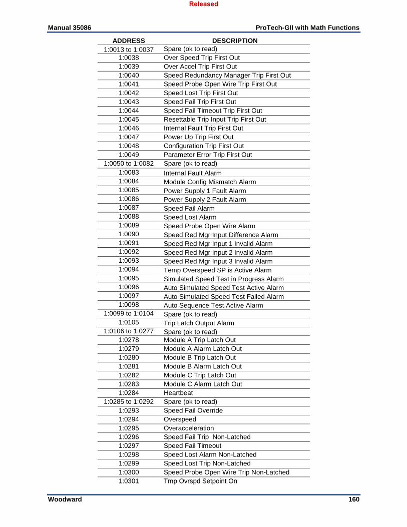
Manual 35086 ProTech-GII with Math Functions
Woodward 160
ADDRESS DESCRIPTION
1:0013 to 1:0037 Spare (ok to read)
1:0038 Over Speed Trip First Out
1:0039 Over Accel Trip First Out
1:0040 Speed Redundancy Manager Trip First Out
1:0041 Speed Probe Open Wire Trip First Out
1:0042 Speed Lost Trip First Out
1:0043 Speed Fail Trip First Out
1:0044 Speed Fail Timeout Trip First Out
1:0045 Resettable Trip Input Trip First Out
1:0046 Internal Fault Trip First Out
1:0047 Power Up Trip First Out
1:0048 Configuration Trip First Out
1:0049 Parameter Error Trip First Out
1:0050 to 1:0082 Spare (ok to read)
1:0083 Internal Fault Alarm
1:0084 Module Config Mismatch Alarm
1:0085 Power Supply 1 Fault Alarm
1:0086 Power Supply 2 Fault Alarm
1:0087 Speed Fail Alarm
1:0088 Speed Lost Alarm
1:0089 Speed Probe Open Wire Alarm
1:0090 Speed Red Mgr Input Difference Alarm
1:0091 Speed Red Mgr Input 1 Invalid Alarm
1:0092 Speed Red Mgr Input 2 Invalid Alarm
1:0093 Speed Red Mgr Input 3 Invalid Alarm
1:0094 Temp Overspeed SP is Active Alarm
1:0095 Simulated Speed Test in Progress Alarm
1:0096 Auto Simulated Speed Test Active Alarm
1:0097 Auto Simulated Speed Test Failed Alarm
1:0098 Auto Sequence Test Active Alarm
1:0099 to 1:0104 Spare (ok to read)
1:0105 Trip Latch Output Alarm
1:0106 to 1:0277 Spare (ok to read)
1:0278 Module A Trip Latch Out
1:0279 Module A Alarm Latch Out
1:0280 Module B Trip Latch Out
1:0281 Module B Alarm Latch Out
1:0282 Module C Trip Latch Out
1:0283 Module C Alarm Latch Out
1:0284 Heartbeat
1:0285 to 1:0292 Spare (ok to read)
1:0293 Speed Fail Override
1:0294 Overspeed
1:0295 Overacceleration
1:0296 Speed Fail Trip Non-Latched
1:0297 Speed Fail Timeout
1:0298 Speed Lost Alarm Non-Latched
1:0299 Speed Lost Trip Non-Latched
1:0300 Speed Probe Open Wire Trip Non-Latched
1:0301 Tmp Ovrspd Setpoint On
Released
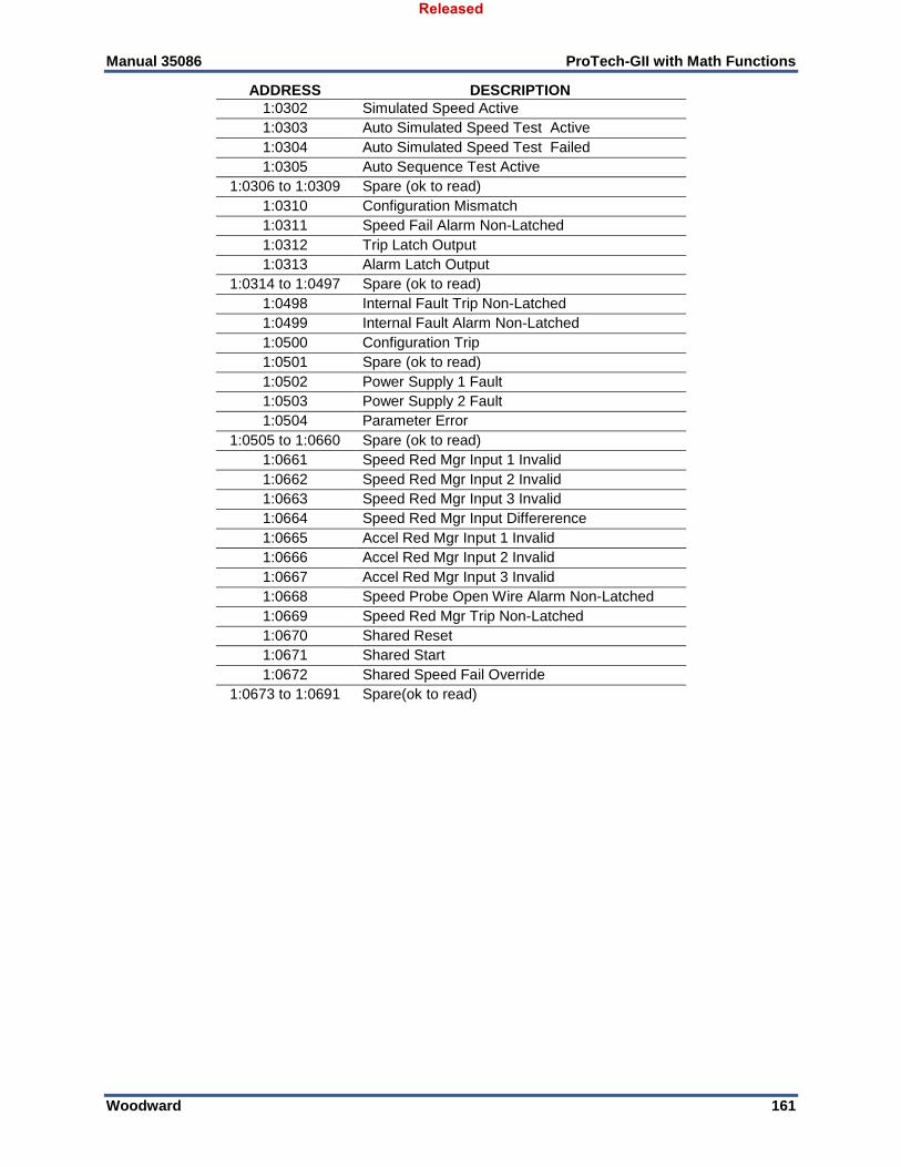
Manual 35086 ProTech-GII with Math Functions
Woodward 161
ADDRESS DESCRIPTION
1:0302 Simulated Speed Active
1:0303 Auto Simulated Speed Test Active
1:0304 Auto Simulated Speed Test Failed
1:0305 Auto Sequence Test Active
1:0306 to 1:0309 Spare (ok to read)
1:0310 Configuration Mismatch
1:0311 Speed Fail Alarm Non-Latched
1:0312 Trip Latch Output
1:0313 Alarm Latch Output
1:0314 to 1:0497 Spare (ok to read)
1:0498 Internal Fault Trip Non-Latched
1:0499 Internal Fault Alarm Non-Latched
1:0500 Configuration Trip
1:0501 Spare (ok to read)
1:0502 Power Supply 1 Fault
1:0503 Power Supply 2 Fault
1:0504 Parameter Error
1:0505 to 1:0660 Spare (ok to read)
1:0661 Speed Red Mgr Input 1 Invalid
1:0662 Speed Red Mgr Input 2 Invalid
1:0663 Speed Red Mgr Input 3 Invalid
1:0664 Speed Red Mgr Input Differerence
1:0665 Accel Red Mgr Input 1 Invalid
1:0666 Accel Red Mgr Input 2 Invalid
1:0667 Accel Red Mgr Input 3 Invalid
1:0668 Speed Probe Open Wire Alarm Non-Latched
1:0669 Speed Red Mgr Trip Non-Latched
1:0670 Shared Reset
1:0671 Shared Start
1:0672 Shared Speed Fail Override
1:0673 to 1:0691 Spare(ok to read)
Released

Manual 35086 ProTech-GII with Math Functions
Woodward 162
Analog Read Table Below is the list of analogs available to read.
Table 9-6. Analog Read Addresses (Code 04)
ADDRESS DESCRIPTION UNITS RANGE
3:0001 Speed (x 0.1) RPM/10 0 to 32767
3:0002 Speed (x 10) RPM*10 0 to 32767
3:0003 Speed (x 100) RPM*100 0 to 32767
3:0004 Speed RM (x 0.1) RPM/10 0 to 32767
3:0005 Speed RM (x 10) RPM*10 0 to 32767
3:0006 Speed RM (x 100) RPM*100 0 to 32767
3:0007 Acceleration (x 0.01) RPM*.01/second -32768 to 32767
3:0008 Acceleration (x 0.1) RPM*.1/second -32768 to 32767
3:0009 Acceleration (x 10) RPM*10/second -32768 to 32767
3:0010 Accel RM (x 0.01) RPM*.01/second -32768 to 32767
3:0011 Accel RM (x 0.1) RPM*.1/second -32768 to 32767
3:0012 Accel RM (x 10) RPM*10/second -32768 to 32767
3:0013 to 3:0020 Spare (ok to read) N/A N/A
3:0021 Speed (after Speed Red Mgr, if used) RPM 0 to 65535
3:0022 Acceleration (after Accel Red Mgr, if used) RPM/second -32768 to 32767
3:0023 Module A Speed RPM 0 to 65535
3:0024 Module A Acceleration RPM/second -32768 to 32767
3:0025 Module B Speed RPM 0 to 65535
3:0026 Module B Acceleration RPM/second -32768 to 32767
3:0027 Module C Speed RPM 0 to 65535
3:0028 Module C Acceleration RPM/second -32768 to 32767
3:0029 Overspeed SetPoint (Local) RPM 0 to 65535
3:0030 to 3:0071 Spare (ok to read) N/A N/A
3:0072 Test Mode Time Remaining seconds 0 to 65535
3:0073 Speed Fail Time Remaining seconds 0 to 65535
3:0074 to 3:0083 Spare (ok to read) N/A N/A
3:0084 Temp Overspeed SetPoint RPM 0 to 65535
3:0085 Simulated Speed RPM RPM 0 to 65535
3:0086 Last Trip Month month 1 to 12
3:0087 Last Trip Day day 1 to 31
3:0088 Last Trip Year year 2000 to 2099
3:0089 Last Trip Hour hour 0 to 23
3:0090 Last Trip Minute minute 0 to 59
3:0091 Last Trip Second second 0 to 59
3:0092 Last Trip Milli-Second millisecond 0 to 999
3:0093 Unit Health Status Enum 0 to 2
3:0094 Auto-Sequence Test Status Enum 0 to 4
Released

Manual 35086 ProTech-GII with Math Functions
Woodward 163
Chapter 10. Safety Management
Product Variations Certified The functional safety requirement in this manual applies to all ProTech-GII variations These products are certified for use in applications up to SIL3 according to IEC61508.
Safe State The ProTech-GII is designed so that the safe state can be configured for either de-energize or energize to trip. De-energize to trip will place trip relays into their unpowered, normally open state. Applications requiring certification up to SIL3 must use the ‘de-energize to trip’ configuration. The energize-to-trip mode does not meet SIL3 safety requirements. The de-energize-to-trip functionality is implemented such that a complete loss of power to the module results in a trip of that module. The energize-to-trip functionality is implemented such that a complete loss of power to the module does not result in a trip of that module. When configured as de-energize-to-trip, the modules power up in the tripped state. When configured as energize-to-trip, the modules power up such that they do not enter the tripped state unless a trip condition is present.
Applications requiring certification up to SIL3 must use the ‘de-energize to trip’ configuration option.
Table 10-1. Trip Relay Safe State Configuration
Configuration Module Power Loss State Module Power Up State
De-energize to trip Tripped Tripped
Energize to trip Not Tripped Not Tripped, unless trip condition present.
SIL Specifications PFD = Probability of Failure to perform a safety function on Demand PFH = Probability of a dangerous Failure per Hour (High Demand or Continuous mode of operation) PFD and PFH calculations have been performed on the ProTech-GII according IEC61508. For SIL3, IEC states the following requirements.
Table 10-2. SIL Specifications
Type SIL 3 Value
PFH 10-8 to 10-7
PFD 10-4 to 10-3
SFF > 90%
Released
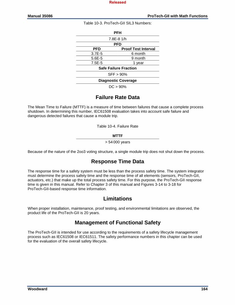
Manual 35086 ProTech-GII with Math Functions
Woodward 164
Table 10-3. ProTech-GII SIL3 Numbers:
PFH
7.8E-8 1/h
PFD
PFD Proof Test Interval
3.7E-5 6 month
5.6E-5 9 month
7.5E-5 1 year
Safe Failure Fraction
SFF > 90%
Diagnostic Coverage
DC > 90%
Failure Rate Data The Mean Time to Failure (MTTF) is a measure of time between failures that cause a complete process shutdown. In determining this number, IEC61508 evaluation takes into account safe failure and dangerous detected failures that cause a module trip.
Table 10-4. Failure Rate
MTTF
> 54 000 years
Because of the nature of the 2oo3 voting structure, a single module trip does not shut down the process.
Response Time Data The response time for a safety system must be less than the process safety time. The system integrator must determine the process safety time and the response time of all elements (sensors, ProTech-GII, actuators, etc.) that make up the total process safety time. For this purpose, the ProTech-GII response time is given in this manual. Refer to Chapter 3 of this manual and Figures 3-14 to 3-18 for ProTech-GII-based response time information.
Limitations When proper installation, maintenance, proof testing, and environmental limitations are observed, the product life of the ProTech-GII is 20 years.
Management of Functional Safety The ProTech-GII is intended for use according to the requirements of a safety lifecycle management process such as IEC61508 or IEC61511. The safety performance numbers in this chapter can be used for the evaluation of the overall safety lifecycle.
Released
Manual 35086 ProTech-GII with Math Functions
Woodward 165
Restrictions The user must complete a full functional check of the ProTech-GII after initial installation, and after any modification of the programming or configuration of the device. This functional check should include as much of the safety system as possible, such as sensors, transmitters, actuators and trip blocks. The ProTech-GII has programming capability to facilitate the automatic checkout and periodic maintenance of the safety system. For help on programming, see the chapters on functionality and configuration. The ProTech-GII must be used within the published specification in this manual.
Competence of Personnel All persons involved in the initial design or modification of the programmable software, installation and maintenance must have appropriate training. Training and guidance materials include this manual, the ProTech-GII Programming and Configuration Tool, and training programs available at Woodward. See Chapter 12 (Service Options) for more information.
Operation and Maintenance Practice A periodic proof (functional) test of the ProTech-GII is required to verify that no dangerous faults not detected by internal run-time diagnostics remain undetected. More information is in the Proof Test Section of this chapter. The frequency of the proof test is determined by the overall safety system design, of which the ProTech-GII is part of the safety system. The safety numbers are given in the following sections to help the system integrator determine the appropriate test interval. This will require password access to the front panel menus.
Installation and Site Acceptance Testing Installation and use of the ProTech-GII must conform to the guidelines and restrictions included in this manual. No other information is needed for installation, programming, and maintenance. This will require password access to the front panel menus.
Functional Testing after Initial Installation A functional test of the ProTech-GII is required prior to use as a safety system. This should be done as part of the overall safety system installation check and should include all I/O interfaces to and from the ProTech-GII that are part of the safety system. For guidance on the functional test, see the proof test procedure below. This will require password access to the front panel menus.
Functional Testing after Changes A functional test of the ProTech-GII is required after making any changes that affect the safety system. Although there are functions in the ProTech-GII that are not directly safety related, it is recommended that a functional test is performed after any change. This will require password access to the front panel menus.
Proof Testing (Functional Test) The ProTech-GII must be periodically proof tested to ensure there are no dangerous faults present that are not detected by on-line diagnostics. Because of the 2oo3 configuration of the ProTech-GII, it is possible to perform the proof test while the ProTech-GII is on-line. Many built-in test modes are included. The test procedure will set the trip outputs on the module under test into a trip state. It is possible to automate several steps of the proof test procedure shown below using the programmability and test mode configurability of the ProTech-GII, but the intent of the steps below must be met. With the procedure below, the user can expect over 99% test coverage of the dangerous failures that are not tested by online diagnostics.
Released
Manual 35086 ProTech-GII with Math Functions
Woodward 166
Functional Verification (Proof) Test Procedure (module level): This procedure requires a digital multi-meter for resistance and voltage measurement. This will require password access to the front panel menus. 1. Cycle Power on the module and verify there are no internal faults on the Alarm Latch page of the
monitor menu. 2. Remove power from one power supply input (power supply input 1 or 2) at a time and verify the
correct fault is read on the Alarm Latch page of the monitor menu. 3. Measure external 24 V EXT (terminals 80—81; 23 ±1 V). 4. Measure SPEED PWR (terminals 69—71). Insure active probe mode is selected in Speed
Configuration Menu, make the measurement, and insure probe type is in original configuration (23 ±1 V).
5. Test Speed input by using one of the internal speed test modes in the Test Menu. Resistance measurement of each of the voter outputs is required. Verify as follows: a. With module not tripped, resistance measurement from 1A—1B, or
2A—2B must be less than 100. b. With module tripped, resistance measurement from 1A—1B, or
2A—2B must be greater than 1 M. 6. Cycle dedicated inputs and verify the proper signal by monitoring the respective input on the Monitor
Menu/Dedicated Discrete Input page of the front panel. 7. If possible, compare external speed with measured speed-reading on the ProTech-GII display. 8. If used as part of the safety system, verify the analog output. Measure this output by performing an
automated overspeed trip test as described in step 6.
9. Chassis isolation checks using resistance measurement. Measure from terminals 66, 67 to a point
on the ProTech-GII chassis (the grounding braid is a good place for this measurement): < 1 . 10. Perform a lamp test from front panel Test Menu.
Released
Manual 35086 ProTech-GII with Math Functions
Woodward 167
Chapter 11 Troubleshooting
Introduction Many troubleshooting features are available from the front panel of each module. In general, the following high level approach can be used to troubleshoot the ProTech-GII control. 1. Check the front-panel LEDs.
2. View the trip and alarm logs by pressing the corresponding view buttons on the front panel
3. Use the messages in the trip and alarm logs to assist in troubleshooting. The messages are summarized in the tables below.
4. Use the Monitor Menu from the front panel to trace and branch to potential I/O, configuration, and programming problems.
5. For more in depth help, use the Programming and Configuration Tool provided with the ProTech-GII. The entry point for troubleshooting the ProTech-GII is the state of the three LEDs on lower part of the front panel. The Trip Log and the Alarm Log can also be viewed from the front panel. The Programming and Configuration Tool also provides more detailed information in the log pages.
UNIT HEALTH LED The UNIT HEALTH LED indicates module health status.
Green – Unit OK and functioning properly. Red – Safety Functionality is not running/internal fault trip is present. Unlit (off) – Status unknown because of a communication fault with the front panel or the module is not powered.
TRIPPED LED The TRIPPED LED indicates the state of the trip latch.
Unlit (off) – Unit not tripped or the module is not powered. Red – Unit tripped, press VIEW button below the LED to toggle between the trip log and trip latch to see the active status on each trip input.
ALARM LED The ALARM LED indicates the state of the alarm latch.
Unlit (off) – No alarms or the module is not powered. Yellow – Active alarms, press VIEW button below LED to toggle between the alarm log and alarm latch to see the active status on each alarm input.
Module Incompatibility Module and software versions are continuously monitored for correct versions. If an incompatibility is detected, the signals and commands from the incompatible module are ignored. The redundancy manager blocks with display these as ‘Invalid’ inputs. Additionally internal fault alarms will be indicated for both software version mismatch and heartbeat error, due to loss of inter-module communications.
Released

Manual 35086 ProTech-GII with Math Functions
Woodward 168
Table 11-1. I/O Troubleshooting
Problem or Diagnostic Indication
Possible Cause Suggested Actions
Power Supply Inputs not working properly. Power supply input alarm present.
Wiring fault, terminal block loose. Power source breaker or fuse open. Only one power supply is connected. Power supply input out of range or insufficient rating.
Verify the wiring and terminal block connections. Verify breaker or fuse. On the front panel, press the VIEW button under the ALARM LED and check for Power Supply 1 or 2 Fault. Check input voltage level and verify it is within acceptable range per electrical specifications. Also check that the power supply has appropriate rating to power the ProTech-GII.
Speed Input not working Wiring fault, terminal block loose. Configuration Alarms and Faults Signal level Active Probe Power
Verify the wiring and terminal block connections. On the front panel, check the Speed Input Configure Menu and verify that all proper configuration options are selected. Verify there are no alarms or faults that may indicate a setup problem (open wire trip, speed lost, speed fail, etc.) Verify the input signal levels are within the electrical specifications. Also verify shield connections. If using an active probe, verify probe power is correct by disconnecting the probe and measuring from terminals 69 to 71. The voltage should be 24 V ±10%. Attach probe and measure again to verify the probe is not overloading the voltage provided by the ProTech-GII.
Dedicated discrete input not working (Start, Reset or Speed Fail Override)
Wiring fault, terminal block loose. Configuration Signal source not working correctly or not within acceptable electrical specifications. Internally supplied wetting voltage fault.
Verify the wiring and terminal block connections. On the front panel, check the Dedicated Discrete Inputs Monitor Menu and verify the logic state is correct. Check signal level and verify it is within acceptable range per electrical specifications. Measure voltage from terminal 1 to terminal 81 and verify it is 23 V ±2 V. If out of range, return unit to Woodward.
Released
Manual 35086 ProTech-GII with Math Functions
Woodward 169
Problem or
Diagnostic Indication Possible Cause Suggested Actions
Trip relays not working Wiring fault, terminal block loose. Configuration External supplies
Verify the wiring and terminal block connections. Using the Programming and Configuration Tool or front panel, check to see that the trip configuration is set correctly. Energize to trip vs. de-energize to trip will invert the polarity on the relays. Check the power supplies that provide voltage to the relay output. If using the 24 V EXT available from the ProTech-GII, measure voltage between terminals 80, 81 and verify 24 V ±10%. If it is not, remove the wiring from the 24 V EXT to unload the output and measure again to verify the voltage is not being overloaded.
Alarm relay output not working
Wiring fault, terminal block loose. External supplies
Verify the wiring and terminal block connections. Check the power supplies that provide voltage to the relay output. If using the 24 V EXT available from the ProTech-GII, measure voltage between terminals 80, 81 and verify 24 V ±10%. If it is not, remove the wiring from the 24 V EXT to unload the output and measure again to verify the voltage is not being overloaded.
Analog Output not working Wiring fault, terminal block loose. Configuration
Verify the wiring and terminal block connections. On the front panel, check the Analog Output on the Monitor Summary screen and verify that the analog output is reading an expected output value. Measure the current from terminal 64 and verify it corresponds to the previous step. Verify the load on the analog output is within the electrical specifications. Using the PCT or front panel, verify the scaling is correct.
Modbus not working Wiring fault, terminal block loose. Configuration
Verify the wiring and terminal block connections. In particular, verify the HI and LO wires are terminated to the correct terminals for RS-485 and likewise for TXD and RXD for RS-232. Also verify the terminations jumpers are installed for RS-485 mode Using the PCT or front panel, verify the correct settings are selected.
Released
Manual 35086 ProTech-GII with Math Functions
Woodward 170
Problem or
Diagnostic Indication Possible Cause Suggested Actions
Programming and Configuration Tool not working
Wiring and connection COM Port
Verify the cable plugged into the DB9 port is not a crossover. A straight-through cable is required. Check that power is applied to the ProTechTPS module and the service tool is connected. Verify the correct COM port is selected when establishing communications and that Auto Detection BAUD rate is selected.
Table 11-2. Trip Indications
Problem or Diagnostic Indication
Description Possible Cause Suggested Actions
Internal Fault trip The module tripped on an internal fault
Various Connect the PCT and view the Module Faults Log. This log expands the Internal Fault annunciation. In general, it is not possible to fix internal faults without returning the unit to Woodward.
Power Up Trip (if configured for De-energize to trip)
The module has lost power and has been restored.
Power source fault or breaker reset.
Verify power source, breaker, fuse and wiring integrity. The Reset function will reset the module.
Configuration Trip The trip was issued from the front panel to enter configuration mode or issued internally to keep module in a tripped state while saving a configuration.
The module is actively being configured or a configuration is being saved.
Wait for module to finish saving configuration. Reset function will reset the module.
Parameter Error An error has been detected in the internally stored parameters. Internally stored parameters are constantly checked for data integrity.
Non-volatile memory hardware fault or internal fault.
Reload configuration settings using the PCT. Cycle input power. If Parameter Error persists return unit to Woodward according to the instructions in Chapter 12 of this manual.
Released
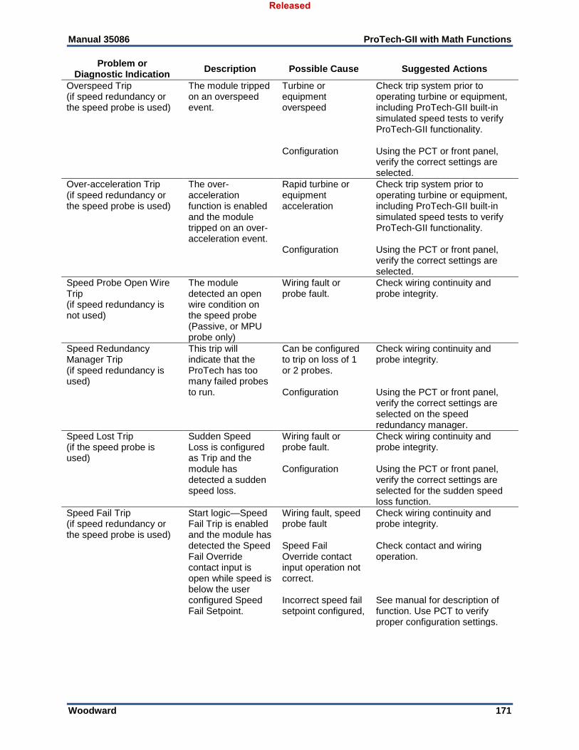
Manual 35086 ProTech-GII with Math Functions
Woodward 171
Problem or Diagnostic Indication
Description Possible Cause Suggested Actions
Overspeed Trip (if speed redundancy or the speed probe is used)
The module tripped on an overspeed event.
Turbine or equipment overspeed Configuration
Check trip system prior to operating turbine or equipment, including ProTech-GII built-in simulated speed tests to verify ProTech-GII functionality. Using the PCT or front panel, verify the correct settings are selected.
Over-acceleration Trip (if speed redundancy or the speed probe is used)
The over-acceleration function is enabled and the module tripped on an over-acceleration event.
Rapid turbine or equipment acceleration Configuration
Check trip system prior to operating turbine or equipment, including ProTech-GII built-in simulated speed tests to verify ProTech-GII functionality. Using the PCT or front panel, verify the correct settings are selected.
Speed Probe Open Wire Trip (if speed redundancy is not used)
The module detected an open wire condition on the speed probe (Passive, or MPU probe only)
Wiring fault or probe fault.
Check wiring continuity and probe integrity.
Speed Redundancy Manager Trip (if speed redundancy is used)
This trip will indicate that the ProTech has too many failed probes to run.
Can be configured to trip on loss of 1 or 2 probes. Configuration
Check wiring continuity and probe integrity. Using the PCT or front panel, verify the correct settings are selected on the speed redundancy manager.
Speed Lost Trip (if the speed probe is used)
Sudden Speed Loss is configured as Trip and the module has detected a sudden speed loss.
Wiring fault or probe fault. Configuration
Check wiring continuity and probe integrity. Using the PCT or front panel, verify the correct settings are selected for the sudden speed loss function.
Speed Fail Trip (if speed redundancy or the speed probe is used)
Start logic—Speed Fail Trip is enabled and the module has detected the Speed Fail Override contact input is open while speed is below the user configured Speed Fail Setpoint.
Wiring fault, speed probe fault Speed Fail Override contact input operation not correct. Incorrect speed fail setpoint configured,
Check wiring continuity and probe integrity. Check contact and wiring operation. See manual for description of function. Use PCT to verify proper configuration settings.
Released
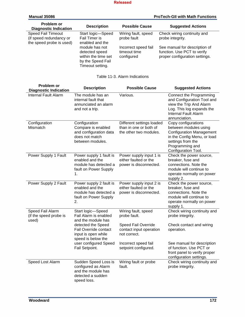
Manual 35086 ProTech-GII with Math Functions
Woodward 172
Problem or Diagnostic Indication
Description Possible Cause Suggested Actions
Speed Fail Timeout (if speed redundancy or the speed probe is used)
Start logic—Speed Fail Timer is enabled and the module has not detected speed within the time set by the Speed Fail Timeout setting.
Wiring fault, speed probe fault Incorrect speed fail timeout time configured
Check wiring continuity and probe integrity. See manual for description of function. Use PCT to verify proper configuration settings.
Table 11-3. Alarm Indications
Problem or Diagnostic Indication
Description Possible Cause Suggested Actions
Internal Fault Alarm The module has an internal fault that annunciated an alarm and not a trip.
Various. Connect the Programming and Configuration Tool and view the Trip And Alarm Log. This log expands the Internal Fault Alarm annunciation.
Configuration Mismatch
Configuration Compare is enabled and configuration data does not match between modules.
Different settings loaded than in one or both of the other two modules.
Copy configurations between modules using Configuration Management in the Config Menu, or load settings from the Programming and Configuration Tool.
Power Supply 1 Fault Power supply 1 fault is enabled and the module has detected a fault on Power Supply 1.
Power supply input 1 is either faulted or the power is disconnected.
Check the power source, breaker, fuse and connections. Note the module will continue to operate normally on power supply 2.
Power Supply 2 Fault Power supply 2 fault is enabled and the module has detected a fault on Power Supply 2.
Power supply input 2 is either faulted or the power is disconnected.
Check the power source, breaker, fuse and connections. Note the module will continue to operate normally on power supply 1.
Speed Fail Alarm (if the speed probe is used)
Start logic—Speed Fail Alarm is enabled and the module has detected the Speed Fail Override contact input is open while speed is below the user configured Speed Fail Setpoint.
Wiring fault, speed probe fault. Speed Fail Override contact input operation not correct. Incorrect speed fail setpoint configured.
Check wiring continuity and probe integrity. Check contact and wiring operation. See manual for description of function. Use PCT or front panel to verify proper configuration settings.
Speed Lost Alarm Sudden Speed Loss is configured as Alarm and the module has detected a sudden speed loss.
Wiring fault or probe fault.
Check wiring continuity and probe integrity.
Released
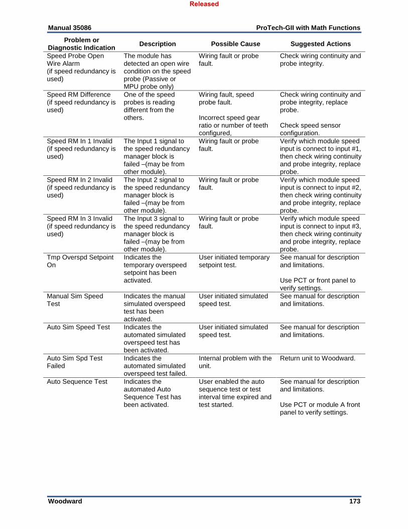
Manual 35086 ProTech-GII with Math Functions
Woodward 173
Problem or Diagnostic Indication
Description Possible Cause Suggested Actions
Speed Probe Open Wire Alarm (if speed redundancy is used)
The module has detected an open wire condition on the speed probe (Passive or MPU probe only)
Wiring fault or probe fault.
Check wiring continuity and probe integrity.
Speed RM Difference (if speed redundancy is used)
One of the speed probes is reading different from the others.
Wiring fault, speed probe fault. Incorrect speed gear ratio or number of teeth configured,
Check wiring continuity and probe integrity, replace probe. Check speed sensor configuration.
Speed RM In 1 Invalid (if speed redundancy is used)
The Input 1 signal to the speed redundancy manager block is failed –(may be from other module).
Wiring fault or probe fault.
Verify which module speed input is connect to input #1, then check wiring continuity and probe integrity, replace probe.
Speed RM In 2 Invalid (if speed redundancy is used)
The Input 2 signal to the speed redundancy manager block is failed –(may be from other module).
Wiring fault or probe fault.
Verify which module speed input is connect to input #2, then check wiring continuity and probe integrity, replace probe.
Speed RM In 3 Invalid (if speed redundancy is used)
The Input 3 signal to the speed redundancy manager block is failed –(may be from other module).
Wiring fault or probe fault.
Verify which module speed input is connect to input #3, then check wiring continuity and probe integrity, replace probe.
Tmp Overspd Setpoint On
Indicates the temporary overspeed setpoint has been activated.
User initiated temporary setpoint test.
See manual for description and limitations. Use PCT or front panel to verify settings.
Manual Sim Speed Test
Indicates the manual simulated overspeed test has been activated.
User initiated simulated speed test.
See manual for description and limitations.
Auto Sim Speed Test Indicates the automated simulated overspeed test has been activated.
User initiated simulated speed test.
See manual for description and limitations.
Auto Sim Spd Test Failed
Indicates the automated simulated overspeed test failed.
Internal problem with the unit.
Return unit to Woodward.
Auto Sequence Test Indicates the automated Auto Sequence Test has been activated.
User enabled the auto sequence test or test interval time expired and test started.
See manual for description and limitations. Use PCT or module A front panel to verify settings.
Released

Manual 35086 ProTech-GII with Math Functions
Woodward 174
Chapter 12. Product Support and Service Options
Product Support Options If you are experiencing problems with the installation, or unsatisfactory performance of a Woodward product, the following options are available:
Consult the troubleshooting guide in the manual.
Contact the manufacturer or packager of your system.
Contact the Woodward Full Service Distributor serving your area.
Contact Woodward technical assistance (see “How to Contact Woodward” later in this chapter) and discuss your problem. In many cases, your problem can be resolved over the phone. If not, you can select which course of action to pursue based on the available services listed in this chapter.
OEM or Packager Support: Many Woodward controls and control devices are installed into the equipment system and programmed by an Original Equipment Manufacturer (OEM) or Equipment Packager at their factory. In some cases, the programming is password-protected by the OEM or packager, and they are the best source for product service and support. Warranty service for Woodward products shipped with an equipment system should also be handled through the OEM or Packager. Please review your equipment system documentation for details. Woodward Business Partner Support: Woodward works with and supports a global network of independent business partners whose mission is to serve the users of Woodward controls, as described here:
A Full Service Distributor has the primary responsibility for sales, service, system integration solutions, technical desk support, and aftermarket marketing of standard Woodward products within a specific geographic area and market segment.
An Authorized Independent Service Facility (AISF) provides authorized service that includes repairs, repair parts, and warranty service on Woodward's behalf. Service (not new unit sales) is an AISF's primary mission.
A Recognized Turbine Retrofitter (RTR) is an independent company that does both steam and gas turbine control retrofits and upgrades globally, and can provide the full line of Woodward systems and components for the retrofits and overhauls, long term service contracts, emergency repairs, etc.
A current list of Woodward Business Partners is available at www.woodward.com/directory.
Product Service Options The following factory options for servicing Woodward products are available through your local Full-Service Distributor or the OEM or Packager of the equipment system, based on the standard Woodward Product and Service Warranty (5-01-1205) that is in effect at the time the product is originally shipped from Woodward or a service is performed:
Replacement/Exchange (24-hour service)
Flat Rate Repair
Flat Rate Remanufacture
Released
Manual 35086 ProTech-GII with Math Functions
Woodward 175
Replacement/Exchange: Replacement/Exchange is a premium program designed for the user who is in need of immediate service. It allows you to request and receive a like-new replacement unit in minimum time (usually within 24 hours of the request), providing a suitable unit is available at the time of the request, thereby minimizing costly downtime. This is a flat-rate program and includes the full standard Woodward product warranty (Woodward Product and Service Warranty 5-01-1205). This option allows you to call your Full-Service Distributor in the event of an unexpected outage, or in advance of a scheduled outage, to request a replacement control unit. If the unit is available at the time of the call, it can usually be shipped out within 24 hours. You replace your field control unit with the like-new replacement and return the field unit to the Full-Service Distributor. Charges for the Replacement/Exchange service are based on a flat rate plus shipping expenses. You are invoiced the flat rate replacement/exchange charge plus a core charge at the time the replacement unit is shipped. If the core (field unit) is returned within 60 days, a credit for the core charge will be issued. Flat Rate Repair: Flat Rate Repair is available for the majority of standard products in the field. This program offers you repair service for your products with the advantage of knowing in advance what the cost will be. All repair work carries the standard Woodward service warranty (Woodward Product and Service Warranty 5-01-1205) on replaced parts and labor. Flat Rate Remanufacture: Flat Rate Remanufacture is very similar to the Flat Rate Repair option with the exception that the unit will be returned to you in “like-new” condition and carry with it the full standard Woodward product warranty (Woodward Product and Service Warranty 5-01-1205). This option is applicable to mechanical products only.
Returning Equipment for Repair If a control (or any part of an electronic control) is to be returned for repair, please contact your Full-Service Distributor in advance to obtain Return Authorization and shipping instructions. When shipping the item(s), attach a tag with the following information:
Return authorization number
Name and location where the control is installed
Name and phone number of contact person
Complete Woodward part number(s) and serial number(s)
Description of the problem
Instructions describing the desired type of repair
Packing a Control Use the following materials when returning a complete control:
Protective caps on any connectors
Antistatic protective bags on all electronic modules
Packing materials that will not damage the surface of the unit
At least 100 mm (4 inches) of tightly packed, industry-approved packing material
A packing carton with double walls
A strong tape around the outside of the carton for increased strength
To prevent damage to electronic components caused by improper handling, read and observe the precautions in Woodward manual 82715, Guide for Handling and Protection of Electronic Controls, Printed Circuit Boards, and Modules.
Released

Manual 35086 ProTech-GII with Math Functions
Woodward 176
Replacement Parts When ordering replacement parts for controls, include the following information:
The part number(s) (XXXX-XXXX) that is on the enclosure nameplate
The unit serial number, which is also on the nameplate
Engineering Services Woodward offers various Engineering Services for our products. For these services, you can contact us by telephone, by email, or through the Woodward website.
Technical Support
Product Training
Field Service Technical Support is available from your equipment system supplier, your local Full-Service Distributor, or from many of Woodward’s worldwide locations, depending upon the product and application. This service can assist you with technical questions or problem solving during the normal business hours of the Woodward location you contact. Emergency assistance is also available during non-business hours by phoning Woodward and stating the urgency of your problem. Product Training is available as standard classes at many of our worldwide locations. We also offer customized classes, which can be tailored to your needs and can be held at one of our locations or at your site. This training, conducted by experienced personnel, will assure that you will be able to maintain system reliability and availability. Field Service engineering on-site support is available, depending on the product and location, from many of our worldwide locations or from one of our Full-Service Distributors. The field engineers are experienced both on Woodward products as well as on much of the non-Woodward equipment with which our products interface. For information on these services, please contact us via telephone, email us, or use our website: www.woodward.com.
Contacting Woodward’s Support Organization For the name of your nearest Woodward Full-Service Distributor or service facility, please consult our worldwide directory at www.woodward.com/directory, which also contains the most current product support and contact information. You can also contact the Woodward Customer Service Department at one of the following Woodward facilities to obtain the address and phone number of the nearest facility at which you can obtain information and service.
Products Used in Electrical Power Systems
Facility --------------- Phone Number
Brazil ------------- +55 (19) 3708 4800
China ----------- +86 (512) 6762 6727
Germany:
Kempen ---- +49 (0) 21 52 14 51
Stuttgart - +49 (711) 78954-510
India --------------- +91 (124) 4399500
Japan --------------- +81 (43) 213-2191
Korea --------------- +82 (51) 636-7080
Poland -------------- +48 12 295 13 00
United States ----- +1 (970) 482-5811
Products Used in Engine Systems
Facility --------------- Phone Number
Brazil ------------- +55 (19) 3708 4800
China ----------- +86 (512) 6762 6727
Germany ------ +49 (711) 78954-510
India --------------- +91 (124) 4399500
Japan --------------- +81 (43) 213-2191
Korea --------------- +82 (51) 636-7080
The Netherlands-- +31 (23) 5661111
United States ----- +1 (970) 482-5811
Products Used in Industrial Turbomachinery Systems
Facility --------------- Phone Number
Brazil ------------- +55 (19) 3708 4800
China ----------- +86 (512) 6762 6727
India --------------- +91 (124) 4399500
Japan --------------- +81 (43) 213-2191
Korea --------------- +82 (51) 636-7080
The Netherlands-- +31 (23) 5661111
Poland -------------- +48 12 295 13 00
United States ----- +1 (970) 482-5811
Released
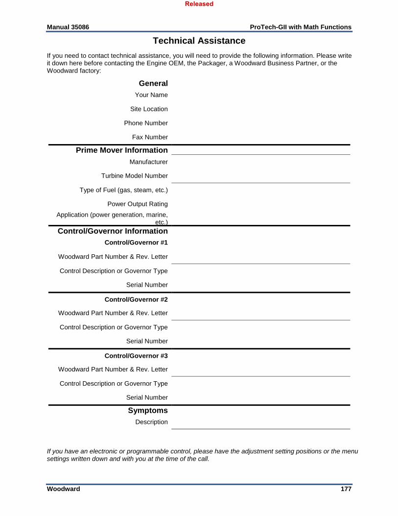
Manual 35086 ProTech-GII with Math Functions
Woodward 177
Technical Assistance
If you need to contact technical assistance, you will need to provide the following information. Please write it down here before contacting the Engine OEM, the Packager, a Woodward Business Partner, or the Woodward factory:
General
Your Name
Site Location
Phone Number
Fax Number
Prime Mover Information
Manufacturer
Turbine Model Number
Type of Fuel (gas, steam, etc.)
Power Output Rating
Application (power generation, marine, etc.)
Control/Governor Information
Control/Governor #1
Woodward Part Number & Rev. Letter
Control Description or Governor Type
Serial Number
Control/Governor #2
Woodward Part Number & Rev. Letter
Control Description or Governor Type
Serial Number
Control/Governor #3
Woodward Part Number & Rev. Letter
Control Description or Governor Type
Serial Number
Symptoms
Description
If you have an electronic or programmable control, please have the adjustment setting positions or the menu settings written down and with you at the time of the call.
Released
Manual 35086 ProTech-GII with Math Functions
Woodward 178
Chapter 13. Asset Management
Product Storage Recommendations The unit may be stored in its original shipping container until it is ready for installation. Protect the device from weather and from extreme humidity or temperature fluctuations during storage. This product is designed for continuous storage in IP56 rated locations with an ambient temperature range of: –20 to +65 °C. To ensure product shelf life, Woodward recommends that a stored ProTech-GII be powered up (power source applied to each module) for 5 minutes every 24 to 36 months. This procedure re-establishes an electrical charge into the product’s electrolytic capacitors, extending their shelf life. (See the Unpacking Section in the chapter on Installation.)
Refurbishment Period Recommendation This product is designed for continuous operation in a typical industrial environment and includes no components that require periodic service. However, to take advantage of related product software and hardware improvements, Woodward recommends that your product be sent back to Woodward or to a Woodward authorized service facility after every five to ten years of continuous service for inspection and component upgrades. Please refer to the service programs in the following chapter.
EXPLOSION HAZARD—Substitution of components may impair suitability for Class I, Division 2.
Released
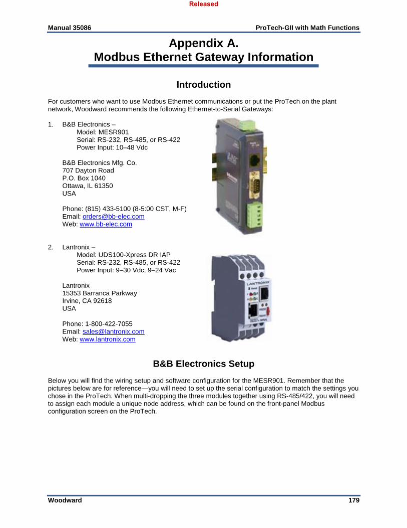
Manual 35086 ProTech-GII with Math Functions
Woodward 179
Appendix A. Modbus Ethernet Gateway Information
Introduction For customers who want to use Modbus Ethernet communications or put the ProTech on the plant network, Woodward recommends the following Ethernet-to-Serial Gateways: 1. B&B Electronics – Model: MESR901 Serial: RS-232, RS-485, or RS-422 Power Input: 10–48 Vdc B&B Electronics Mfg. Co. 707 Dayton Road P.O. Box 1040 Ottawa, IL 61350 USA Phone: (815) 433-5100 (8-5:00 CST, M-F) Email: [email protected] Web: www.bb-elec.com 2. Lantronix – Model: UDS100-Xpress DR IAP Serial: RS-232, RS-485, or RS-422 Power Input: 9–30 Vdc, 9–24 Vac Lantronix 15353 Barranca Parkway Irvine, CA 92618 USA Phone: 1-800-422-7055 Email: [email protected] Web: www.lantronix.com
B&B Electronics Setup Below you will find the wiring setup and software configuration for the MESR901. Remember that the pictures below are for reference—you will need to set up the serial configuration to match the settings you chose in the ProTech. When multi-dropping the three modules together using RS-485/422, you will need to assign each module a unique node address, which can be found on the front-panel Modbus configuration screen on the ProTech.
Released
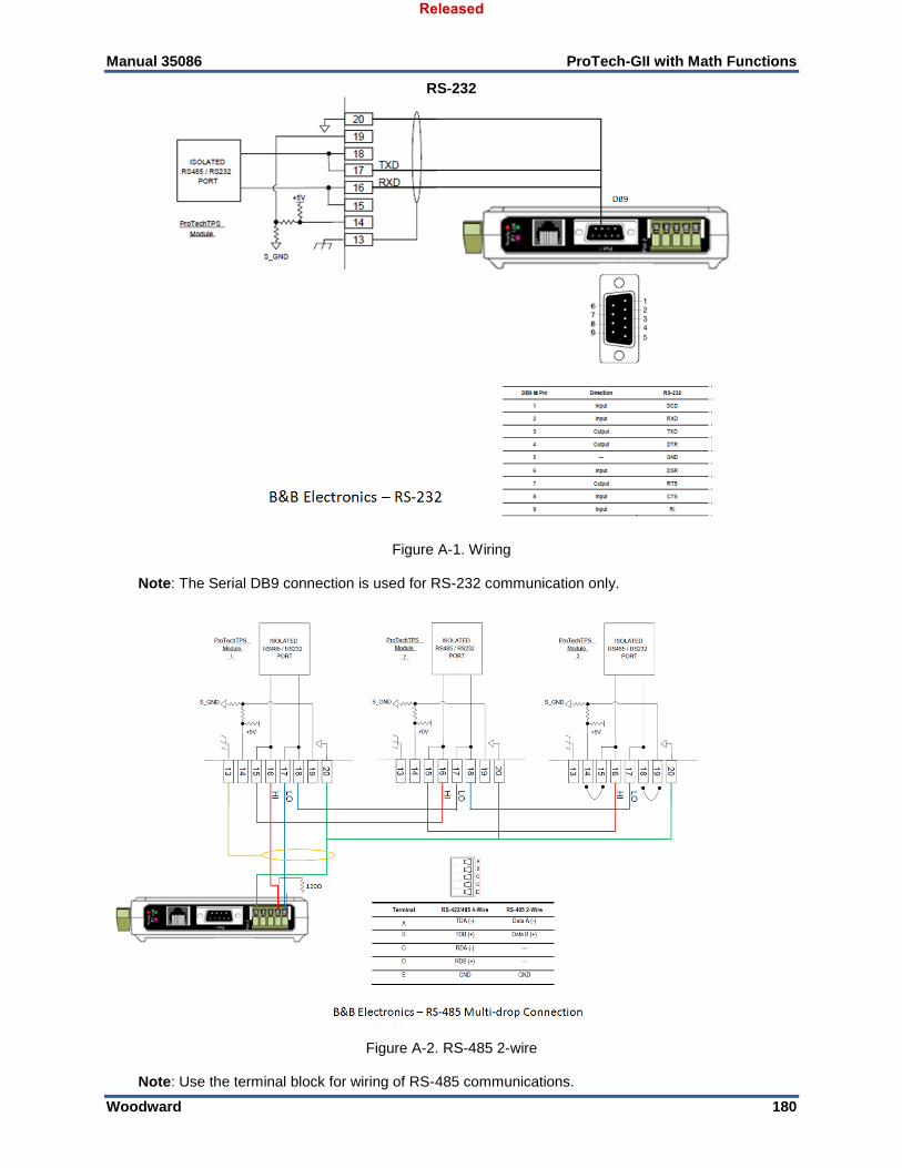
Manual 35086 ProTech-GII with Math Functions
Woodward 180
RS-232
Figure A-1. Wiring
Note: The Serial DB9 connection is used for RS-232 communication only.
Figure A-2. RS-485 2-wire
Note: Use the terminal block for wiring of RS-485 communications.
Released
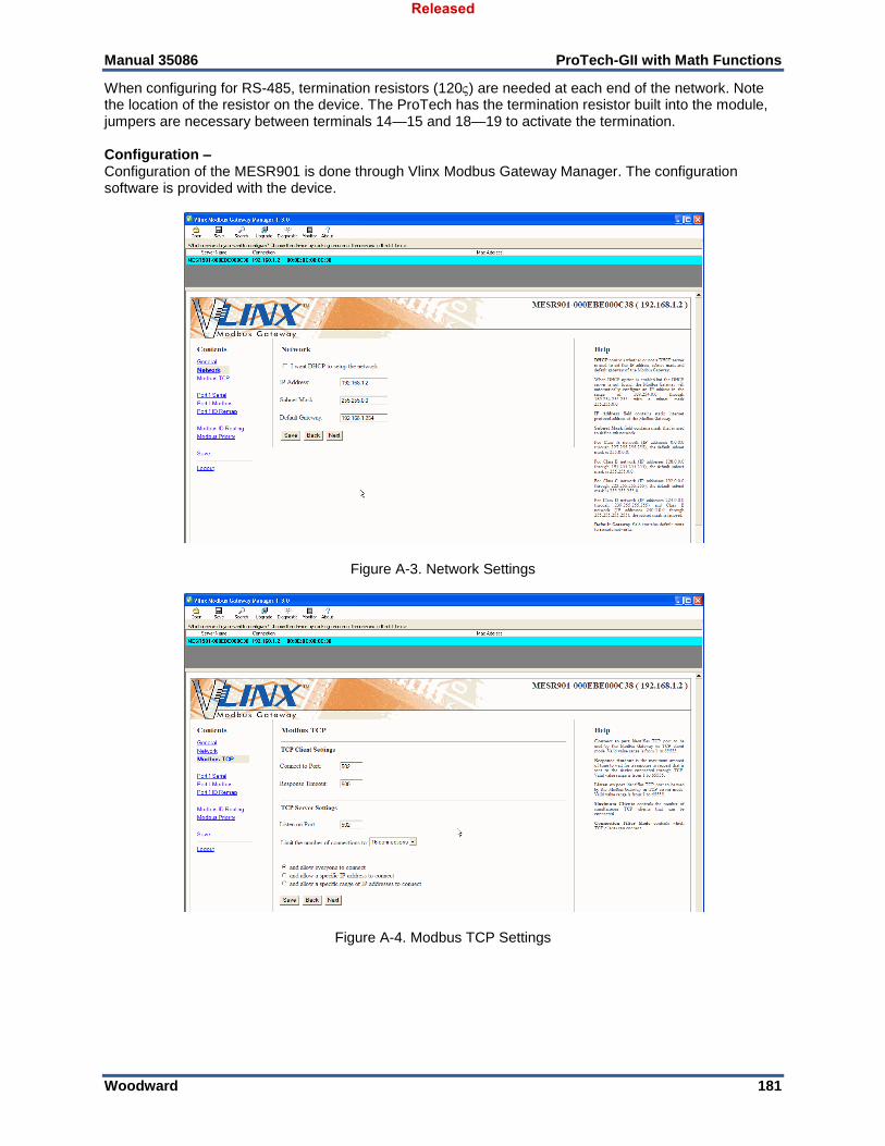
Manual 35086 ProTech-GII with Math Functions
Woodward 181
When configuring for RS-485, termination resistors (120) are needed at each end of the network. Note the location of the resistor on the device. The ProTech has the termination resistor built into the module, jumpers are necessary between terminals 14—15 and 18—19 to activate the termination. Configuration – Configuration of the MESR901 is done through Vlinx Modbus Gateway Manager. The configuration software is provided with the device.
Figure A-3. Network Settings
Figure A-4. Modbus TCP Settings
Released
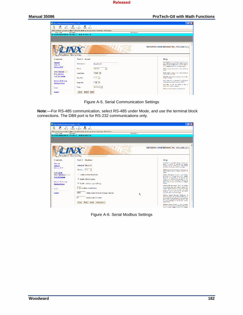
Manual 35086 ProTech-GII with Math Functions
Woodward 182
Figure A-5. Serial Communication Settings
Note:—For RS-485 communication, select RS-485 under Mode, and use the terminal block connections. The DB9 port is for RS-232 communications only.
Figure A-6. Serial Modbus Settings
Released
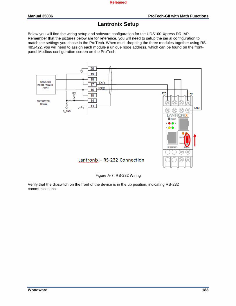
Manual 35086 ProTech-GII with Math Functions
Woodward 183
Lantronix Setup Below you will find the wiring setup and software configuration for the UDS100-Xpress DR IAP. Remember that the pictures below are for reference, you will need to setup the serial configuration to match the settings you chose in the ProTech. When multi-dropping the three modules together using RS-485/422, you will need to assign each module a unique node address, which can be found on the front-panel Modbus configuration screen on the ProTech.
Figure A-7. RS-232 Wiring
Verify that the dipswitch on the front of the device is in the up position, indicating RS-232 communications.
Released
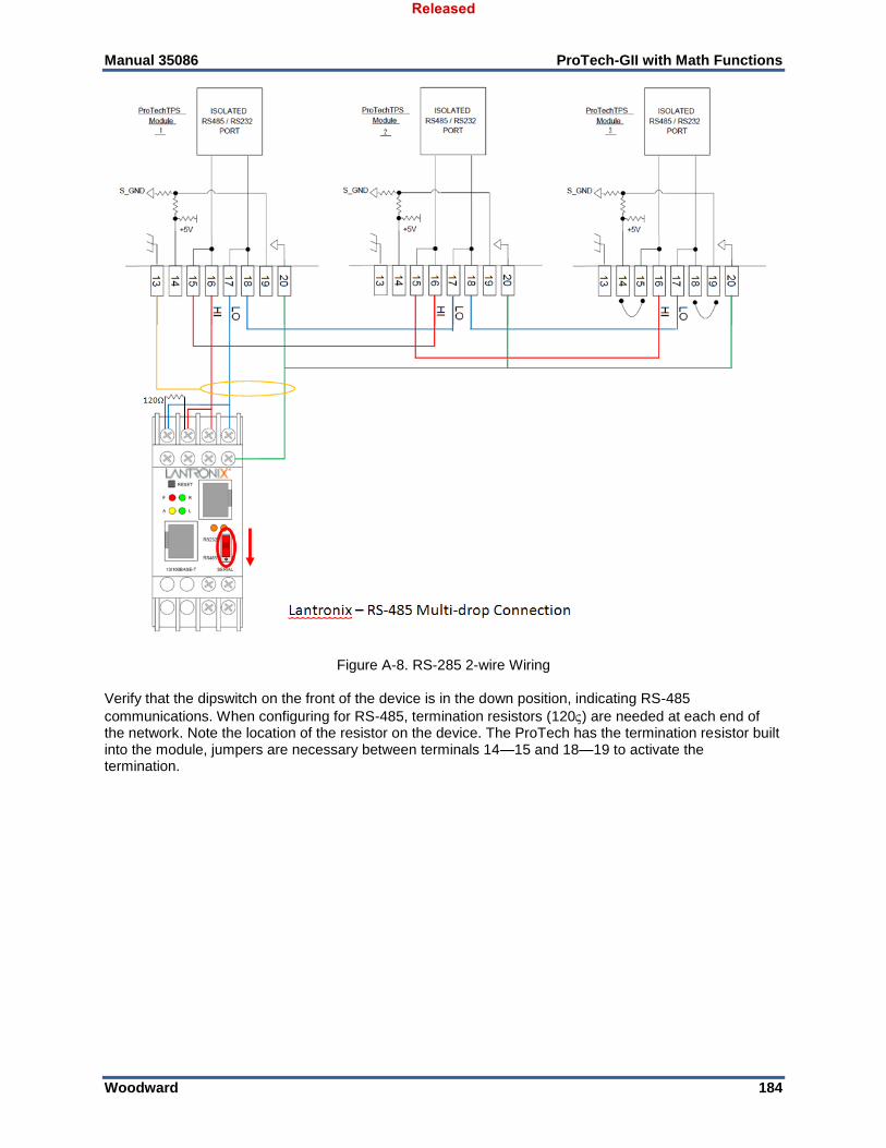
Manual 35086 ProTech-GII with Math Functions
Woodward 184
Figure A-8. RS-285 2-wire Wiring Verify that the dipswitch on the front of the device is in the down position, indicating RS-485
communications. When configuring for RS-485, termination resistors (120) are needed at each end of the network. Note the location of the resistor on the device. The ProTech has the termination resistor built into the module, jumpers are necessary between terminals 14—15 and 18—19 to activate the termination.
Released
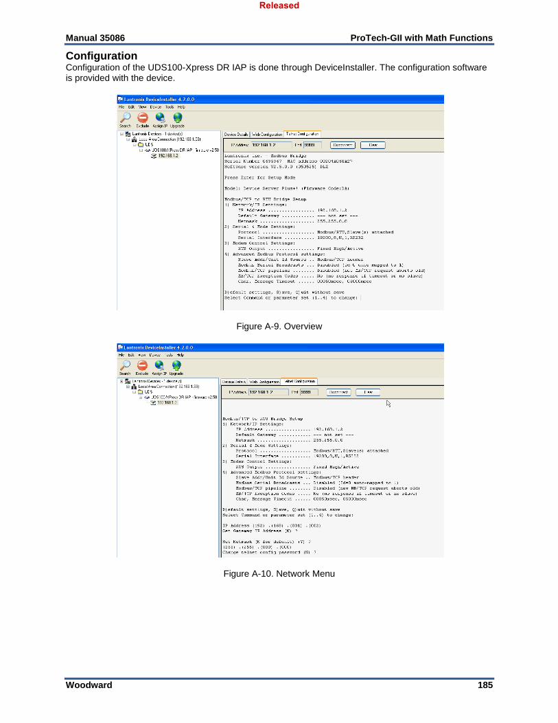
Manual 35086 ProTech-GII with Math Functions
Woodward 185
Configuration Configuration of the UDS100-Xpress DR IAP is done through DeviceInstaller. The configuration software is provided with the device.
Figure A-9. Overview
Figure A-10. Network Menu
Released
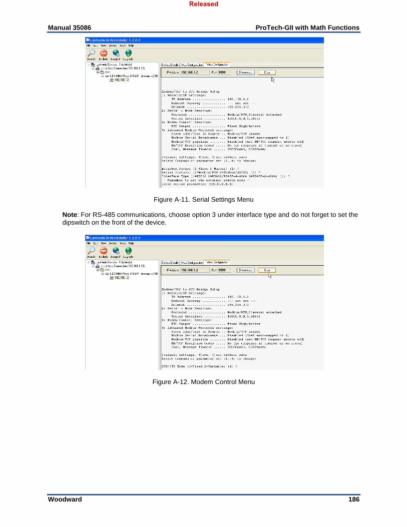
Manual 35086 ProTech-GII with Math Functions
Woodward 186
Figure A-11. Serial Settings Menu
Note: For RS-485 communications, choose option 3 under interface type and do not forget to set the dipswitch on the front of the device.
Figure A-12. Modem Control Menu
Released
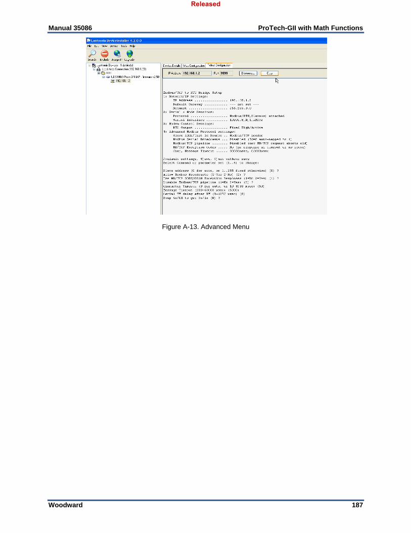
Manual 35086 ProTech-GII with Math Functions
Woodward 187
Figure A-13. Advanced Menu
Released
Manual 35086 ProTech-GII with Math Functions
Woodward 188
Appendix B. ProTech-GII Configuration Worksheet
ProTech-GII Part Number:__________________ Date:_____________ ProTech-GII Serial Number:________________ Site/Application:______________________ CONFIGURATION FUNCTIONS (Minimum Required) Configuration of the unit can be done directly on the front panel display or the PCT software. PASSWORD CHANGE: Test Level Password _______________ Config Level Password _______________
Released
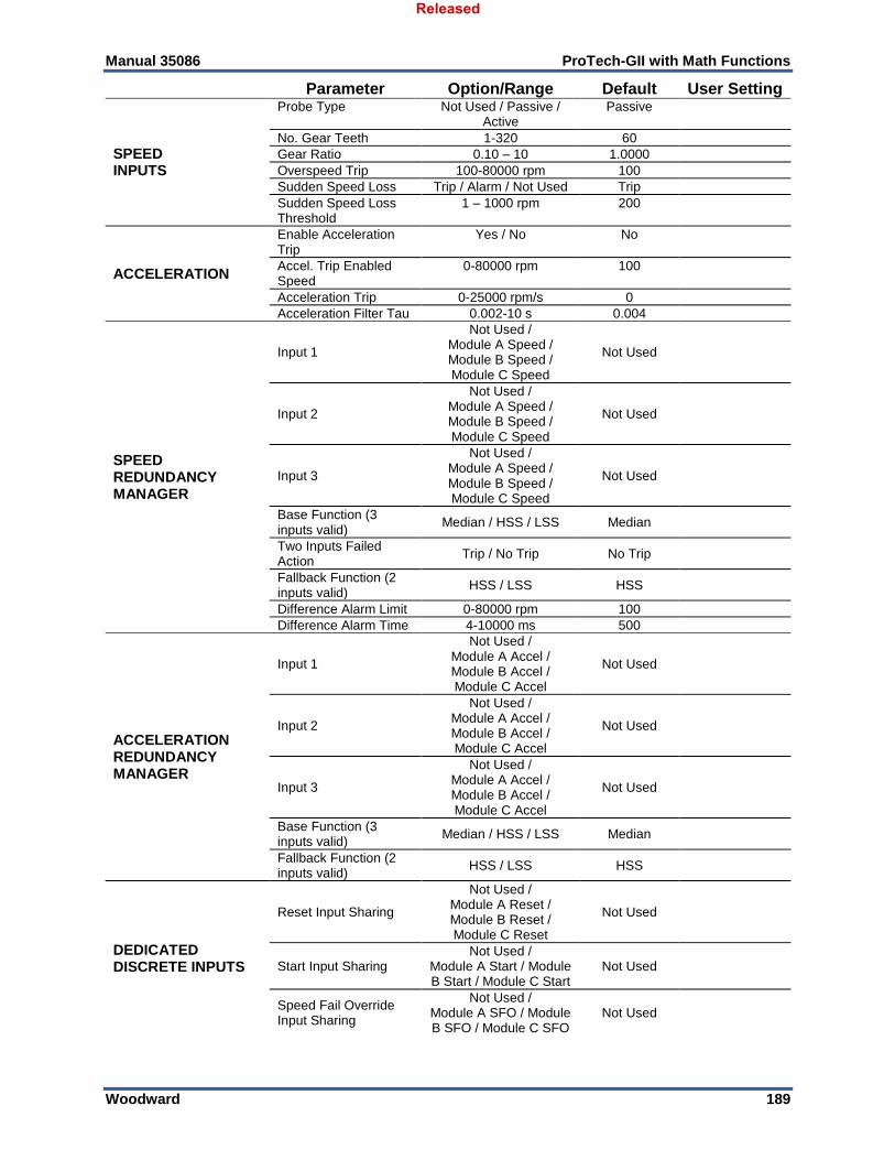
Manual 35086 ProTech-GII with Math Functions
Woodward 189
Parameter Option/Range Default User Setting
SPEED INPUTS
Probe Type Not Used / Passive / Active
Passive
No. Gear Teeth 1-320 60
Gear Ratio 0.10 – 10 1.0000
Overspeed Trip 100-80000 rpm 100
Sudden Speed Loss Trip / Alarm / Not Used Trip
Sudden Speed Loss Threshold
1 – 1000 rpm 200
ACCELERATION
Enable Acceleration Trip
Yes / No No
Accel. Trip Enabled Speed
0-80000 rpm 100
Acceleration Trip 0-25000 rpm/s 0
Acceleration Filter Tau 0.002-10 s 0.004
SPEED REDUNDANCY MANAGER
Input 1
Not Used / Module A Speed / Module B Speed / Module C Speed
Not Used
Input 2
Not Used / Module A Speed / Module B Speed / Module C Speed
Not Used
Input 3
Not Used / Module A Speed / Module B Speed / Module C Speed
Not Used
Base Function (3 inputs valid)
Median / HSS / LSS Median
Two Inputs Failed Action
Trip / No Trip No Trip
Fallback Function (2 inputs valid)
HSS / LSS HSS
Difference Alarm Limit 0-80000 rpm 100
Difference Alarm Time 4-10000 ms 500
ACCELERATION REDUNDANCY MANAGER
Input 1
Not Used / Module A Accel / Module B Accel / Module C Accel
Not Used
Input 2
Not Used / Module A Accel / Module B Accel / Module C Accel
Not Used
Input 3
Not Used / Module A Accel / Module B Accel / Module C Accel
Not Used
Base Function (3 inputs valid)
Median / HSS / LSS Median
Fallback Function (2 inputs valid)
HSS / LSS HSS
DEDICATED DISCRETE INPUTS
Reset Input Sharing
Not Used / Module A Reset / Module B Reset / Module C Reset
Not Used
Start Input Sharing Not Used /
Module A Start / Module B Start / Module C Start
Not Used
Speed Fail Override Input Sharing
Not Used / Module A SFO / Module B SFO / Module C SFO
Not Used
Released
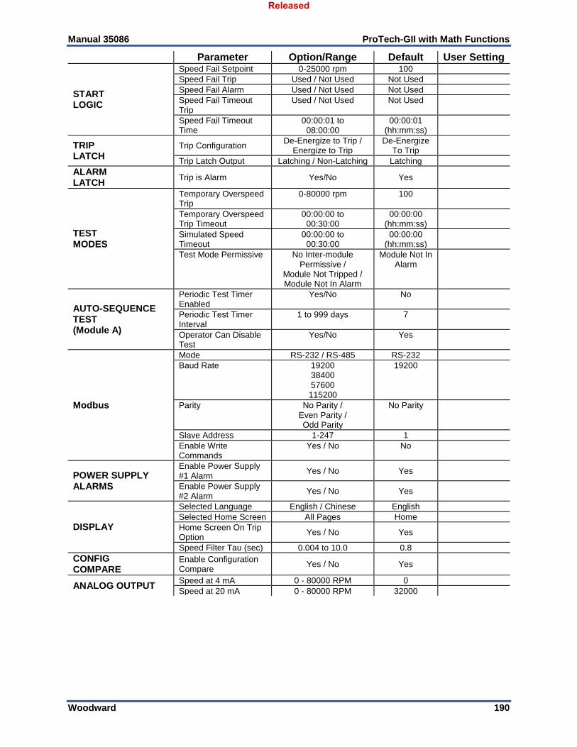
Manual 35086 ProTech-GII with Math Functions
Woodward 190
Parameter Option/Range Default User Setting
START LOGIC
Speed Fail Setpoint 0-25000 rpm 100
Speed Fail Trip Used / Not Used Not Used
Speed Fail Alarm Used / Not Used Not Used
Speed Fail Timeout Trip
Used / Not Used Not Used
Speed Fail Timeout Time
00:00:01 to 08:00:00
00:00:01 (hh:mm:ss)
TRIP LATCH
Trip Configuration De-Energize to Trip /
Energize to Trip De-Energize
To Trip
Trip Latch Output Latching / Non-Latching Latching
ALARM LATCH
Trip is Alarm Yes/No Yes
TEST MODES
Temporary Overspeed Trip
0-80000 rpm 100
Temporary Overspeed Trip Timeout
00:00:00 to 00:30:00
00:00:00 (hh:mm:ss)
Simulated Speed Timeout
00:00:00 to 00:30:00
00:00:00 (hh:mm:ss)
Test Mode Permissive No Inter-module Permissive /
Module Not Tripped / Module Not In Alarm
Module Not In Alarm
AUTO-SEQUENCE TEST (Module A)
Periodic Test Timer Enabled
Yes/No No
Periodic Test Timer Interval
1 to 999 days 7
Operator Can Disable Test
Yes/No Yes
Modbus
Mode RS-232 / RS-485 RS-232
Baud Rate 19200 38400 57600 115200
19200
Parity No Parity / Even Parity / Odd Parity
No Parity
Slave Address 1-247 1
Enable Write Commands
Yes / No No
POWER SUPPLY ALARMS
Enable Power Supply #1 Alarm
Yes / No Yes
Enable Power Supply #2 Alarm
Yes / No Yes
DISPLAY
Selected Language English / Chinese English
Selected Home Screen All Pages Home
Home Screen On Trip Option
Yes / No Yes
Speed Filter Tau (sec) 0.004 to 10.0 0.8
CONFIG COMPARE
Enable Configuration Compare
Yes / No Yes
ANALOG OUTPUT Speed at 4 mA 0 - 80000 RPM 0
Speed at 20 mA 0 - 80000 RPM 32000
Released

Manual 35086 ProTech-GII with Math Functions
Woodward 191
Revision History Revision A—
Edited ATEX – Potentially Explosive Atmospheres Directive in the Regulatory and Compliance section
Added RoHS and RCM certifications to the Regulatory and Compliance section
Removed WEE, C-Tick, and EuP Directives from the Regulatory and Compliance section
Changed part numbers in Table 1-2
Released

Manual 35086 ProTech-GII with Math Functions
Woodward 192
Declarations
Released

We appreciate your comments about the content of our publications.
Send comments to: [email protected]
Please reference publication 35086.
ÌB35086è:è-´¸µ¹´»Î
PO Box 1519, Fort Collins CO 80522-1519, USA 1041 Woodward Way, Fort Collins CO 80524, USA
Phone +1 (970) 482-5811
Email and Website—www.woodward.com
Woodward has company-owned plants, subsidiaries, and branches, as well as authorized distributors and other authorized service and sales facilities throughout the world.
Complete address / phone / fax / email information for all locations is available on our website.
Released