protection cag 14 & cag 34 - system controls &...
TRANSCRIPT

GRID
PROTECTION
1
CAG14 relay is applied for high impedance restricted earth fault protection of generator, transformer, reactor and bus bars. It is also used with a follower timer for time delayed earth fault protection. Other applications include capacitor bank unbalance protection, generator inter turn fault protection etc.
Features
• Simple and robust construction.• High stability on external faults.• Sensitive high speed protection on
internal faults.
Application• Differential protection of ac machines,
reactors, auto transformers and bus bars.
• Balanced and restricted earth fault protection of generators and transformer windings.
• Transverse differential protection of generators and parallel feeders.
ApplicationIn circulating current protection schemes, the sudden and often asymmetrical growth of the system current during external fault conditions can cause the protective current transformers to go into saturation, resulting in a high unbalanced current. To ensure stability under these conditions, the modern practice is to use a voltage operated, high impedance relay, set to operate at a voltage slightly higher than that developed by the current transformers under maximum external fault conditions.
Type CAG 14 relay, used with a stabilizing resistor, is designed for such applications where sensitive settings with stability on heavy through faults are required.
Type CAG 14 relay has its operating coil connected in series with small choke and capacitor forming a series resonant circuit. This circuit is energized from an internal autotransformer which is tapped to provide seven equally spaced current settings.
The relay circuit, tuned to the supply frequency, rejects the harmonics produced by CT saturation. A slight time delay on operation helps to provide stability on heavy external faults and is obtained by allowing the auto transformer to saturateabove the relay setting. This limits the current supplied, and the relay operates only on the slower part of its time/current curve.
The external stabilizing resistor supplied with the relay allows continuous adjustment of the relay voltage setting over a wide range. The total impedance of the relay and the series stabilizing resistor is usually low enough to prevent the current transformers developing voltages over 2 kV during maximum internal faults, but in some applications a non-linear resistor is required to limit this voltage.
Types CAG 14 and CAG 34 are single and triple pole relays respectively.
Customer Benefits• High stability on external
faults• Tuned to rated frequency.• 25ms operating time at 5
times current setting
Circulating Current RelayCAG 14 & CAG 34

CAG14 withdrawn from case
2
CAG 14 & CAG 34
Technical dataCurrent rating1A or 5A
Settings20-80% or 10-40% - in seven equal steps as standard.Continuously variable external stabilising resistors of 200 and 50 ohms are supplied as standard for 1A and 5A relays respectively. Stabilizing resistors with other ohmic values are also available.
Operating time25 milliseconds at 5 times the current setting (see time/current characteristic in Figure 1).
Burdens0.9VA at current setting on lowest tap. 1.0VA at current setting on highest tap.
Current transformer requirements will be given on request.
Short time20x setting current for 3 seconds.
AccuracyError class indexE 5.0 as per BS 142 - 1966 and5.0 as per IS 3231 – 1965
Operation indicatorHand reset operation indicator provided.
ContactsTwo pairs of self reset`make’ contacts.Insulation. The relay meets the requirements of IS 3231 -1965/IEC 255-5 Series C- 2 kV for 1 minute.
External and internal circuit connectionsSee Figure 2.

Figure 1:Time/current characteristic
Figure 2:Typical external and internal circuit connections for type CAG 34 generator differential relay
Figure 1: Time/current characteristic
Figure 2: Typical external and internal circuit connections for type CAG 34 generator differential relay
3
CAG 14 & CAG 34
Figure 1:Time/current characteristic
Figure 2:Typical external and internal circuit connections for type CAG 34 generator differential relay
4
CAG 14 & CAG 34
Therrmal ratingThe maximum continuous current rating for 60o crise coil temperature are as follows:
Operatingcoil tap
Lowest tap1
2 3 4 5 6 Highest tap7
Times current setting 8.5 7.74 6.9 6.4 5.74 5.3 5.05
Contact ratings
Make and carryContinuously
Make and carryfor 0.5 second
Break
AC 1250VA with maxima of 5A and 660V 7500VA with maxima of 30A and 660V 1250VA with maxima of 5A and 660V
DC 1250W with maxima of 5A and 660V 7500W with maxima of 30A and 660V 100W(resisitive) 50W (inductive) with maxima of 5A and 660V
Dimensions and weights
Relay Maximum overall dimensions Approximategross weight
KgCase size Height
mmWidthmm
Depth*mm
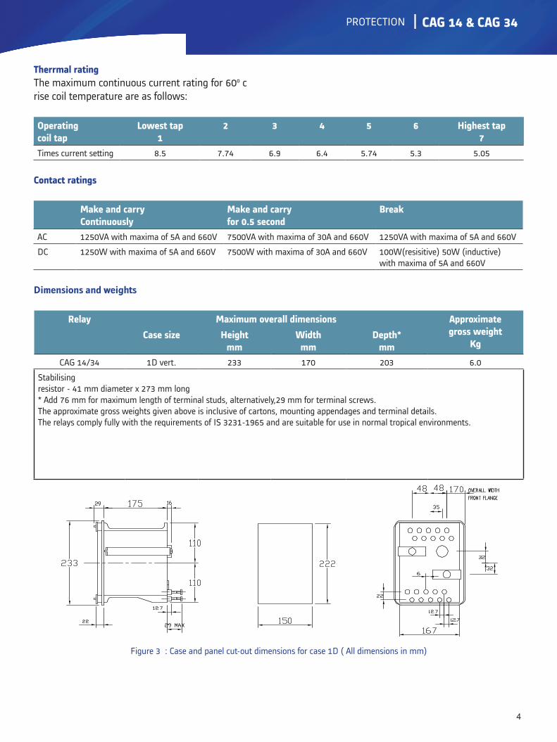
CAG 14/34 1D vert. 233 170 203 6.0
Stabilisingresistor - 41 mm diameter x 273 mm long* Add 76 mm for maximum length of terminal studs, alternatively,29 mm for terminal screws.The approximate gross weights given above is inclusive of cartons, mounting appendages and terminal details.The relays comply fully with the requirements of IS 3231-1965 and are suitable for use in normal tropical environments.
Figure 3 : Case and panel cut-out dimensions for case 1D ( All dimensions in mm)

5
CAG 14 & CAG 34
Case and finish
1D vertical drawout case suitable for flush mounting finished twin tone and tropicalised. Suitable trip isolating switches and CT shorting switches provided on cradle assembly/case.
Information required with order
1. Type of relay. CAG 14 CAG 34
2. Current transformer secondary rating. 1A 5A
3. Current setting range. 20-80% 10-40%
4. a. Application. Res. E/F Differential Buszone Protection

GRID
6
CAG 14 & CAG 34
ALSTOM T&D INDIA LIMITEDPallavaram Works19/1, G.S.T. Road,Pallavaram, Chennai - 600 043Tel: 91-44-2264 8000Fax: 91-44-2264 0040
ALSTOM T&D Worldwide Contact Centre:http://www.alstom.com/contactcentre/Tel.: +44 (0) 1785 250 070
www.grid.alstom.com
“Alst
om lo
go a
nd a
ny a
ltern
ativ
e ve
rsio
n th
ereo
f are
trad
emar
ks a
nd s
ervi
ce m
arks
of A
lstom
. The
oth
er n
ames
men
tione
d, re
gist
ered
or n
ot, a
re th
e pr
oper
ty o
f the
ir re
spec
tive
com
pani
es. T
he te
chni
cal a
nd o
ther
dat
a co
ntai
ned
in th
e do
cum
ent a
re p
rovi
ded
for i
nfor
mat
ion
only.
Nei
ther
ALS
TOM
, its
offi
cers
nor
em
ploy
ees a
ccep
t res
pons
ibili
ty fo
r or s
houl
d be
take
n as
mak
ing
any
repr
esen
tatio
n or
war
rant
y (w
heth
er e
xpre
ss o
r im
plie
d) a
s to
the
accu
racy
or c
ompl
eten
ess o
f suc
h da
ta o
r the
ach
ieve
men
ts o
f any
pro
ject
ed p
erfo
rman
ce
crite
ria w
here
thes
e ar
e in
dica
ted.
No
liabi
lity
is ac
cept
ed fo
r any
relia
nce
plac
ed u
pon
the
info
rmat
ion
cont
aine
d in
this
broc
hure
. Alst
om re
serv
es th
e rig
ht to
revi
se o
r cha
nge
thes
e da
ta a
t any
tim
e w
ithou
t fur
ther
not
ice.”