protection & control challenges with distributed...
TRANSCRIPT

Protection & Control Challenges
with
Distributed Generation
Pankaj Sharma, P Eng.
Grid Operations Manager Operating Effectiveness
Networks Operating DivisionHydro One Networks Inc.
July 2015
© 2015 Hydro One. All rights reserved. Operating Effectiveness Hydro One Networks Inc

OBJECTIVES
Identify major Protection & Control (P&C) Challenges with
Distributed Generation (DG) Connections
Discuss Mitigation of P&C Challenges
Acknowledge advantages of Transfer-Trip (TT) Application
Foster important role of P&C in enabling DG
© 2015 Hydro One. All rights reserved. Operating Effectiveness Hydro One Networks Inc

Background
Impacts on P&C assets, Challenges & Solutions
Transmission Side
Distribution Side
Operating issues and mitigations
DG Interconnection Protection Challenges
Utility Protection
Advantages of the Transfer Trip
Example of an Islanding event with UFLS operation
Summary
AGENDA
© 2015 Hydro One. All rights reserved. Operating Effectiveness Hydro One Networks Inc

DistributionSystem(Dx)
50kV & Below
1. Transmission Station (feeders, buses, transformers etc) 2. Transmission lines
1. Distribution Station Fuses, Transformers, Re-closers etc)
2. Distribution lines
BACKGROUNDOntario T & D
(P&C) Protection & Control
© 2015 Hydro One. All rights reserved.
TransmissionSystem(Tx)
Above 50kV
Operating Effectiveness Hydro One Networks Inc

© 2015 Hydro One. All rights reserved.
Total DG Connected - mid 2015
Wind 473 MWSolar 1236 MW
Bio/CoGen 185 MW
Gas 362 MW Hydro 383 MW
Other (Steam)
226 MW
Micro 115 MW(Each project <
10 KW)
Total Distributed Generation connected at Distribution: 2865 MW
Wind Solar Bio/CoGen Gas Hydro Other (Steam) Micro
Operating Effectiveness Hydro One Networks Inc
© 2015 Hydro One. All rights reserved.
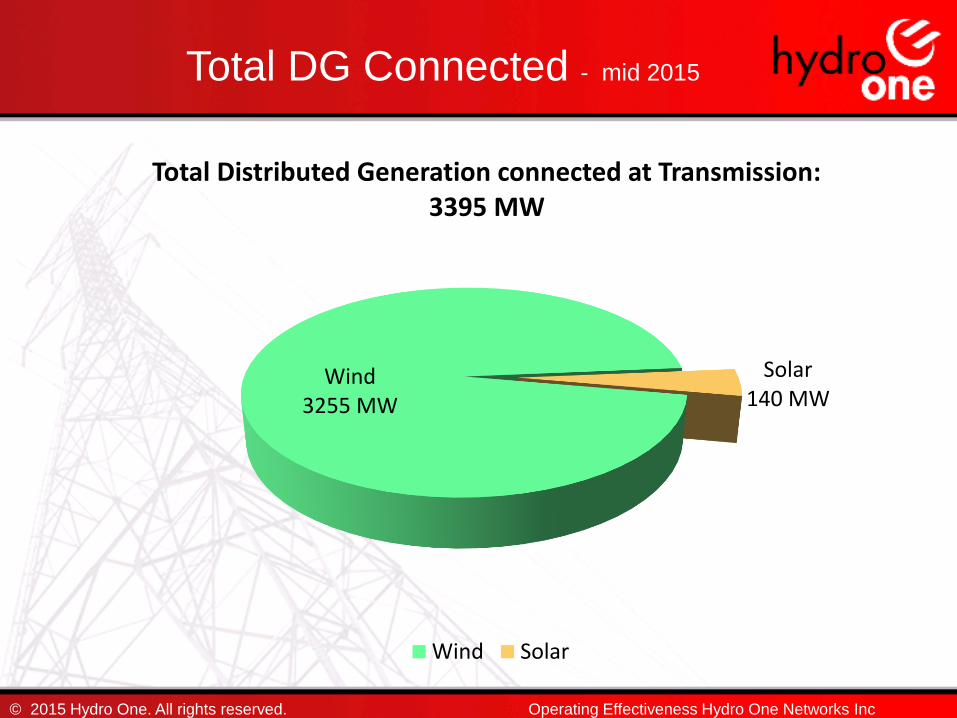
Total DG Connected - mid 2015
Wind3255 MW
Solar140 MW
Total Distributed Generation connected at Transmission: 3395 MW
Wind Solar
Operating Effectiveness Hydro One Networks Inc
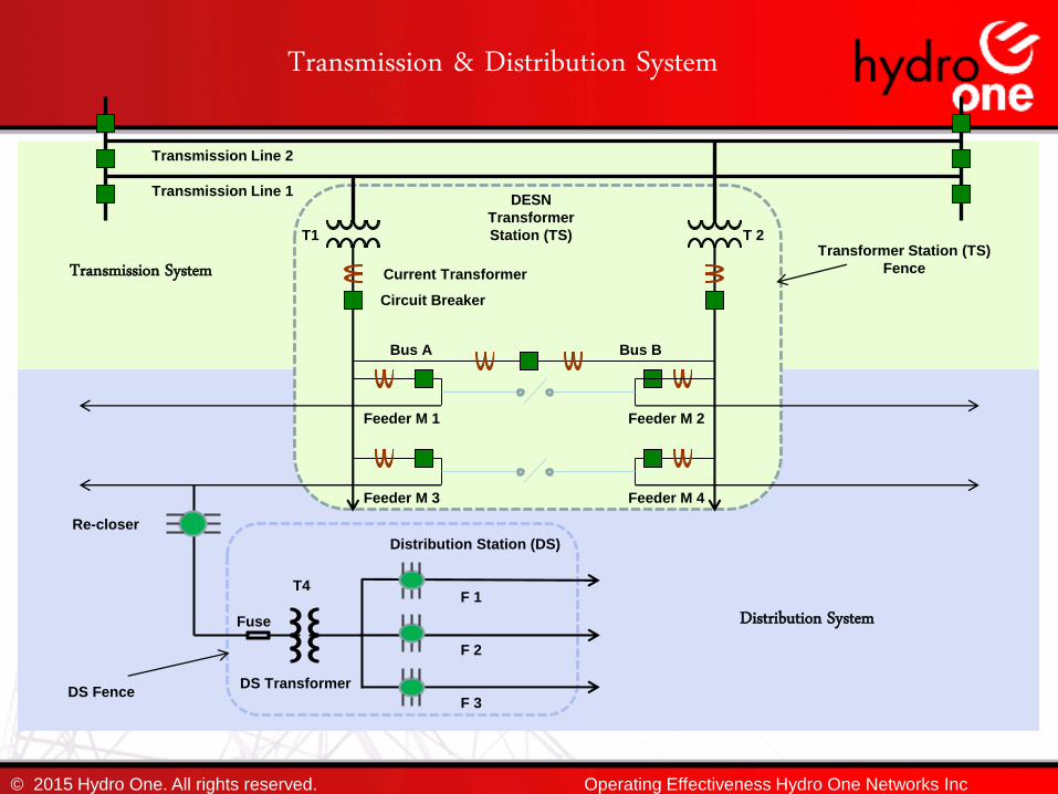
DESN
Transformer
Station (TS)
Transmission & Distribution System
Bus A Bus B
Transmission Line 1
Transmission Line 2
F 1
T1 T 2
© 2015 Hydro One. All rights reserved.
Transformer Station (TS)
Fence
Feeder M 2Feeder M 1
Feeder M 3 Feeder M 4
Transmission System
Distribution SystemT4
F 2
F 3
Re-closer
DS TransformerDS Fence
Circuit Breaker
Current Transformer
Fuse
Distribution Station (DS)
Operating Effectiveness Hydro One Networks Inc

Impacts on P&C assetsTransmission Side
Impacts on the Transformer Station (TS)
Feeder protection
Bus protection, Line back-up
Transformer protection, Automatic Voltage Reg
Ground Potential Rise, Neutralizing
Transformer, Neutral Grounding Reactor
Existing Special Protection Schemes (Load
Rejection and Generation Rejection schemes)
Network Management System
Under Frequency Load Shedding
Impacts on the Transmission Line
© 2015 Hydro One. All rights reserved. Operating Effectiveness Hydro One Networks Inc
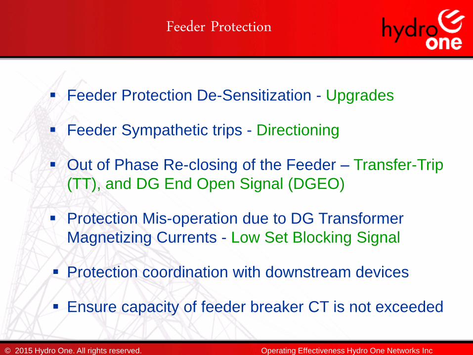
Feeder Protection
Feeder Protection De-Sensitization - Upgrades
Feeder Sympathetic trips - Directioning
Out of Phase Re-closing of the Feeder – Transfer-Trip
(TT), and DG End Open Signal (DGEO)
Protection Mis-operation due to DG Transformer
Magnetizing Currents - Low Set Blocking Signal
Protection coordination with downstream devices
Ensure capacity of feeder breaker CT is not exceeded
© 2015 Hydro One. All rights reserved. Operating Effectiveness Hydro One Networks Inc

Bus Protection
Low impedance Bus differential protection is
not affected but may no longer prove to be
secure
Bus blocking scheme must be reviewed and
may need directioning
Bus blocking scheme is not affected by DG for
faults occurring on the feeder
Bus blocking scheme is affected by DG for faults occurring on the bus
© 2015 Hydro One. All rights reserved. Operating Effectiveness Hydro One Networks Inc

Bus Blocking Scheme – Feeder Fault
Transmission System
DESN Transformer Station
Feeder 1 Feeder 2
Bus A Bus B
F1 CB opens
Forced Outage
Fault current flows thru feeder
protection and bus protection
CTs. 50B-Abus 50B-Bbus
F1-21 F2-21
Feeder Fault on Feeder F1
Line 1
Line 2
T1 T2
Bus B Protection
I Bbus relay = ∑ IT2 + -IT2 = 0
- Bus B also remains in service.
Bus A ProtectionI Abus relay = ∑ IT1 + IT2 = IF
- 32 ms coordination delay
- F1 block signal prevents trip
Bus A remains in service.
Feeder protection operates, sends
a bus blocking signal to Bus A.
© 2015 Hydro One. All rights reserved. Operating Effectiveness Hydro One Networks Inc
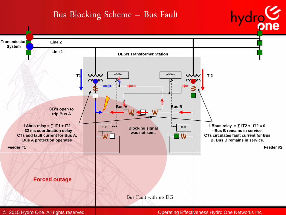
Bus Blocking Scheme – Bus Fault
Transmission
System
DESN Transformer Station
Feeder #1 Feeder #2
Bus A Bus BCB’s open to
trip Bus A
Forced outage
I Abus relay = ∑ IT1 + IT2
- 32 ms coordination delay
CTs add fault current for Bus A;
Bus A protection operates
I Bbus relay = ∑ IT2 + -IT2 = 0
- Bus B remains in service.
CTs circulates fault current for Bus
B; Bus B remains in service.
Blocking signal was not sent.
Bus Fault with no DG
50B-Abus 50B-Bbus
F1-21 F2-21
Line 1
Line 2
T1 T 250B-Abus 50B-Bbus
F1-21 F2-21
© 2015 Hydro One. All rights reserved. Operating Effectiveness Hydro One Networks Inc

Bus Blocking – Bus Fault
Transmission
System
Feeder #1 Feeder #2
Bus A Bus B
PROBLEM:
With DG present, CT at bus tie
measures additional DG fault current
which creates an imbalance causing
the protection for the healthy Bus B to
false operate. Bus forced outage is
more widespread than necessary.
CTs add fault current for Bus A;
Bus A protection operates
Forced outage
SOLUTION:
Directioning of B bus
blocking relays will
prevent false operation for
faults on A bus. This allows
faults to be precisely
isolated.
Feeder 2 protection
does not operate
because directioned
thus blocking signal
is not sent
Bus Fault with DG on feeder F2
50B-Abus 50B-Bbus
F1-21 F2-21
DESN Transformer StationLine 1
Line 2
T1 T2
© 2015 Hydro One. All rights reserved.
No fault current at
Feeders of bus A
thus no operation
and blocking signal
not sent
Operating Effectiveness Hydro One Networks Inc

Tra
ns
fer
Tri
p
Lin
e
Pro
tecti
on
s
Lin
e
Pro
tecti
on
s
DESN Transformer Station
Bus ABus B
Line Back-Up ProtectionStation Supplied by Two Transmission Lines
A fault on one transmission line can be
fed by the other transmission line
because the transformer station creates
a path for electric current between the
two lines
Line Protections detect the fault and
respond by taking the line out of service.
Also, a Transfer Trip Signal is sent to the
TS so that the LV CB will open. This cuts
off the electrical path between the two
lines.
In case the Transfer Trip fails however,
line back-up protection is required. Line
back-up is implemented at the station,
and can also signal the LV CB to open
during a line fault.
All TS’s fed by two lines are equipped with
Line Back-Up Protection.
Forced Outage
Line Back-Up
Protection
Tra
nsfe
r
Tri
p
© 2015 Hydro One. All rights reserved.
Line 1
Line 2
T1 T2
M 1 M 2
M 3 M 4
Operating Effectiveness Hydro One Networks Inc
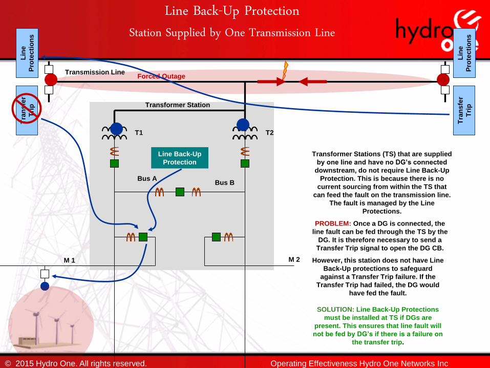
Tra
nsfe
r
Tri
p
Tra
nsfe
r
Tri
pTransformer Station
Bus ABus B
Line Back-Up ProtectionStation Supplied by One Transmission Line
Transformer Stations (TS) that are supplied
by one line and have no DG’s connected
downstream, do not require Line Back-Up
Protection. This is because there is no
current sourcing from within the TS that
can feed the fault on the transmission line.
The fault is managed by the Line
Protections.
Lin
e
Pro
tecti
on
s
Lin
e
Pro
tecti
on
s
Forced Outage
PROBLEM: Once a DG is connected, the
line fault can be fed through the TS by the
DG. It is therefore necessary to send a
Transfer Trip signal to open the DG CB.
SOLUTION: Line Back-Up Protections
must be installed at TS if DGs are
present. This ensures that line fault will
not be fed by DG’s if there is a failure on
the transfer trip.
Line Back-Up
Protection
However, this station does not have Line
Back-Up protections to safeguard
against a Transfer Trip failure. If the
Transfer Trip had failed, the DG would
have fed the fault.
© 2015 Hydro One. All rights reserved.
T1 T2
Transmission Line
M 1 M 2
Operating Effectiveness Hydro One Networks Inc

Transformer P & C
Transformer Differential protection at stations having three winding transformers; needs to be upgraded to provide separate restraint windings
Transformer LV breaker re-closing scheme may need changes (sync-check may be needed)
Restricted ground fault protection may be required if the NGR impedance is increased
© 2015 Hydro One. All rights reserved. Operating Effectiveness Hydro One Networks Inc

Transformer P & C
Overload protections, monitoring of reverse flows, total current harmonics and winding temperatures may also be required
ULTC voltage regulation may have to be reviewed/changed for reverse P / forward Q flows
Volts/Hertz relay may need to be considered for over-fluxing
© 2015 Hydro One. All rights reserved. Operating Effectiveness Hydro One Networks Inc
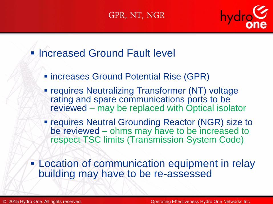
GPR, NT, NGR
Increased Ground Fault level
increases Ground Potential Rise (GPR)
requires Neutralizing Transformer (NT) voltage rating and spare communications ports to be reviewed – may be replaced with Optical isolator
requires Neutral Grounding Reactor (NGR) size to be reviewed – ohms may have to be increased to respect TSC limits (Transmission System Code)
Location of communication equipment in relay building may have to be re-assessed
© 2015 Hydro One. All rights reserved. Operating Effectiveness Hydro One Networks Inc

Existing SPS
Review existing Special Protection System (SPS)
Load Rejection (LR) and Generation Rejection (GR) schemes
Modifications may be required
New Generation Rejection Schemes may be required
© 2015 Hydro One. All rights reserved. Operating Effectiveness Hydro One Networks Inc

Network Management System (NMS)
Upgrades needed to match the changes due to DG
HMI display changes are required at NMS and LCC
Existing Hub sites capacity issue and new sites
Unbundle IED relay failure alarms for selectivity
© 2015 Hydro One. All rights reserved. Operating Effectiveness Hydro One Networks Inc
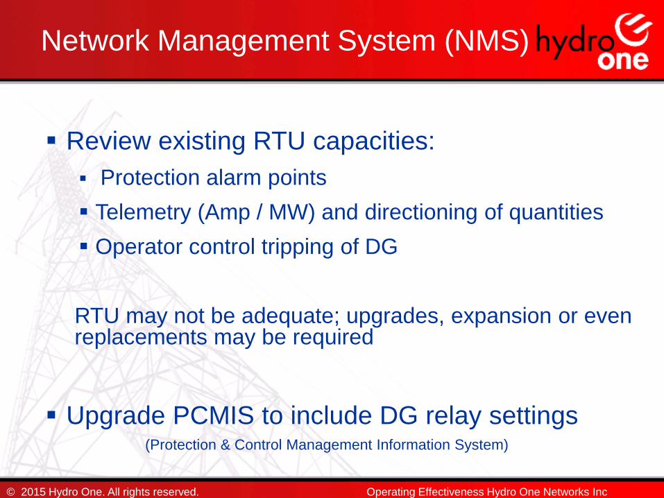
Review existing RTU capacities:
Protection alarm points
Telemetry (Amp / MW) and directioning of quantities
Operator control tripping of DG
RTU may not be adequate; upgrades, expansion or even replacements may be required
Upgrade PCMIS to include DG relay settings(Protection & Control Management Information System)
© 2015 Hydro One. All rights reserved.
Network Management System (NMS)
Operating Effectiveness Hydro One Networks Inc

Under Frequency Load Shedding(UFLS)
Review existing UFLS scheme
Re-configure feeder selection in UFLS
Feeders with DG - to be excluded, or
Real time intelligence in selecting feeder under UFLS (dynamic arming), or
Extending UFLS to DS and re-closer level
© 2015 Hydro One. All rights reserved. Operating Effectiveness Hydro One Networks Inc
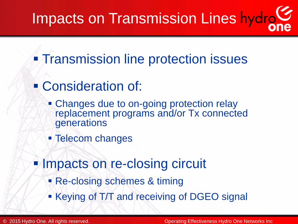
Impacts on Transmission Lines
Transmission line protection issues
Consideration of:
Changes due to on-going protection relay replacement programs and/or Tx connected generations
Telecom changes
Impacts on re-closing circuit
Re-closing schemes & timing
Keying of T/T and receiving of DGEO signal
© 2015 Hydro One. All rights reserved. Operating Effectiveness Hydro One Networks Inc

Transmission Lines Protection Issues
© 2015 Hydro One. All rights reserved. Operating Effectiveness Hydro One Networks Inc
Non-Overlapping Zone 1 Protections
Enlarged apparent impedance
Current Out feed (Current Reversal)

Non-Overlapping Zone 1 Protections
If zone 1 elements are required not to trip fault beyond new tapped generation CB, the instantaneous zone 1 protection will not be overlapping. The gap area between the reaches of two zone 1s must be protected by teleprotection scheme.
Terminal
Station 1Terminal
Station 2
New Generator
Zone 1Zone 1
Existing customers
© 2015 Hydro One. All rights reserved. Operating Effectiveness Hydro One Networks Inc

Enlarged apparent impedance
121221111
IG
IZL
ZIIZIZIVZApp
Terminal
Station 1
Terminal
Station 2
New Generator
IG
I1 I2
Z1 Z2
© 2015 Hydro One. All rights reserved. Operating Effectiveness Hydro One Networks Inc

Current Out feed (Current Reversal)
When a paralleling path exists, the tappedgeneration may cause current reversal. Thedistance element will sense a fault close to theremote station as a backward fault.
Terminal
Station 1
Terminal
Station 2
Existing Generator
IG_2
I1 I2
Z1 Z2
I3
New Generator
IG_1
Z3
L1
L2
© 2015 Hydro One. All rights reserved. Operating Effectiveness Hydro One Networks Inc

Impacts on P&C assetsDistribution Side
Feeder re-closer controller settings, protection coordination & fuse saving?
Need for HV side automatic interrupting device at DS?
Incorporate blocking scheme?
Un-cleared low level faults between existing HV fuse and station re-closer section?
Sympathetic Tripping - false tripping of a healthy feeder on adjacent feeder faults?
Need for communications at re-closers?
© 2015 Hydro One. All rights reserved. P & C Planning, Network Development & Regional Panning
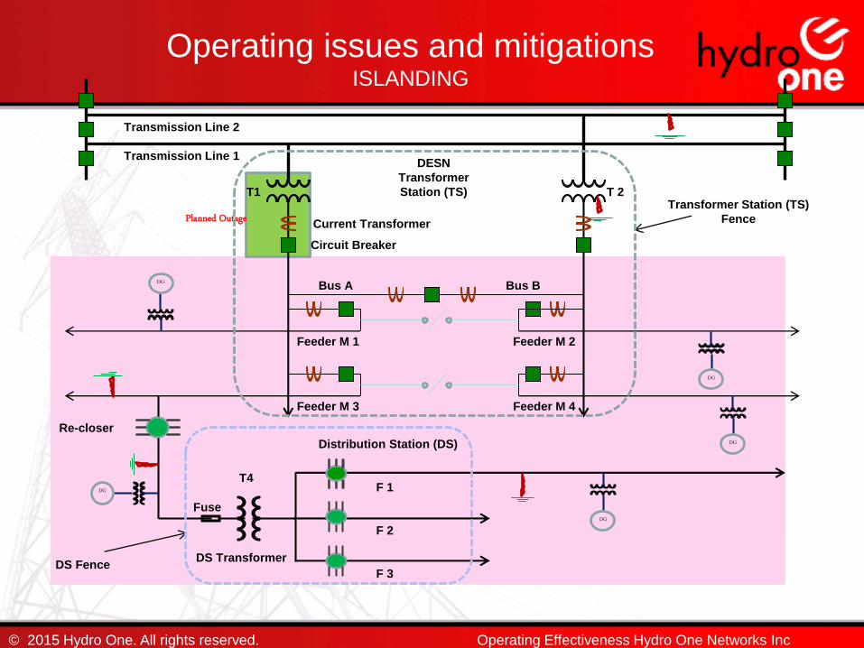
Planned Outage
DESN
Transformer
Station (TS)
Operating issues and mitigationsISLANDING
Bus A Bus B
Transmission Line 1
Transmission Line 2
F 1
T1 T 2
© 2015 Hydro One. All rights reserved.
Transformer Station (TS)
Fence
Feeder M 2Feeder M 1
Feeder M 3 Feeder M 4
T4
F 2
F 3
Re-closer
DS TransformerDS Fence
Circuit Breaker
Current Transformer
Fuse
Distribution Station (DS)
DG
DG
DG
DG
DG
Operating Effectiveness Hydro One Networks Inc
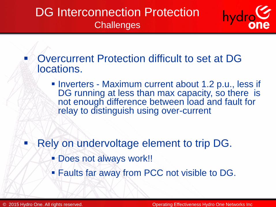
Overcurrent Protection difficult to set at DG locations.
Inverters - Maximum current about 1.2 p.u., less if DG running at less than max capacity, so there is not enough difference between load and fault for relay to distinguish using over-current
Rely on undervoltage element to trip DG.
Does not always work!!
Faults far away from PCC not visible to DG.
© 2015 Hydro One. All rights reserved.
DG Interconnection ProtectionChallenges
Operating Effectiveness Hydro One Networks Inc

Challenges …
What about Distance Protection?
Zone 1 = 75-80% of Z1
(Instantaneous fault clearance for overlap zone, and high speed trip for rest).
Zone 2 (P) = 120-125% of Max Apparent Impedance.
(High speed or Fast trip for entire line and backed-up with Time Delay trip, usually 400ms).
By setting Zone 2 to 120% of the Max Apparent Impedance for remote 3 phase fault, the relay reach becomes huge.
With interface transformer HV winding ungrounded the ground distance protection not applicable
© 2015 Hydro One. All rights reserved. Operating Effectiveness Hydro One Networks Inc
Inverters limit fault current & maintain constant power factor dynamically.
Inverters behaviour during fault is important before determining the suitability of the relaying at the DG.
Inverters modeled as a current limiting source
© 2015 Hydro One. All rights reserved.
Challenges …
Operating Effectiveness Hydro One Networks Inc

DG in-feed to a fault anywhere on the Dx can be virtually identical for inverters.
All Dx/Tx faults are in the same direction. Direction cannot be used to avoid tripping for faults on adjacent feeders.
Current only, voltage only or distance cannot be used to avoid tripping for faults on adjacent feeders.
However, distance offers greater precision compared to overcurrent when reach discrimination is required.
© 2015 Hydro One. All rights reserved.
DG Interconnection Protection Typical shortcomings
Operating Effectiveness Hydro One Networks Inc

DG never is certain of the fault location and whether it needs to trip or ride through. Without TT - DG need to delay tripping (at least 150ms) after the utility trips.
Even with the longer delays it is difficult to avoid DG nuisance trips for adjacent feeder permanent faults that are cleared by timed protection elements.
Delay may be too long – due to declining fault infeeds– risk asynchronous reclosing into DG + feeder island.
© 2015 Hydro One. All rights reserved.
DG Interconnection Protection Typical shortcomings
Operating Effectiveness Hydro One Networks Inc
Utility protection has visibility of entire feeder.
Utility feeder protections are capable of selective detection and isolation of all faults on the feeder.
With fault location discrimination it is determined whether or not the DG needs to be tripped for a feeder fault condition.
© 2015 Hydro One. All rights reserved.
Utility Protection
Operating Effectiveness Hydro One Networks Inc
Where current magnitude alone is not sufficient, utility feeder protection use direction to avoid tripping for DG back-feeds to source-side faults (adjacent feeder)
Transfer Trip (TT) can extend utility protection to the DG for fast clearing.
Sequential delay is unavoidable when DG is not capable of detecting feeder faults & there is no TT
© 2015 Hydro One. All rights reserved.
Utility Protection
Operating Effectiveness Hydro One Networks Inc

Adaptive Relaying
Distribution Generation Control Protection (DGCP)
Real Time Automation Controller (RTAC) can provide the mechanism to reconfigure both the sending and receiving protection signals to/from remote field devices and feeder breakers whenever changes occur in the feeder topologies.
The Distribution Management System (DMS) sends topology changes to the DGCP and the DGCP automatically re-configures the protection signals based on the new topology.
Automatically switching setting groups and summing CTs prior to entering or after exiting back-to-back parallel of feeders.
© 2015 Hydro One. All rights reserved.
Utility Protection
Operating Effectiveness Hydro One Networks Inc

Adaptive Relaying …
Blocking the tripping for 44kV reclosers for a loss-of-protection.
Ground backup protection at the DS to open the 44kV recloser at the station for a 27.6/13.8/8.2 kV station recloser failure condition.
The UFLS infrastructure to allow adaptive relaying by evaluating feeder loading conditions by the DMS and having DMS automatically arm selections in real-time at the TS station, 44kV reclosers and 27.6/13.8/8.2 kV DS station reclosers based on the DG generation and loading to satisfy the target load rejection requirement at the TS.
The 27.6/13.8/8.2 kV capacitor banks and voltage regulators can be provided with new controllers and remote control but still switch automatically based on the voltage but with the added remote control switching capability.
© 2015 Hydro One. All rights reserved.
Utility Protection
Operating Effectiveness Hydro One Networks Inc

Advantages of Transfer Trip
© 2015 Hydro One. All rights reserved.
TRANSFER
TRIP
NO
Non-Detection-Zone
Expedites
Restoration Efforts
Facilitates
DGEO, LSBS
TIMELESS
Operates for
Inadvertent Trips
Deterministic,
Most Reliable &
Safest
Fault Ride-
Through Possible
(LVRT, LFRT)
Provides Rapid
Fault Clearance,
Fuse Saving,
Power Quality
Operating Effectiveness Hydro One Networks Inc

M1 M4
M3 M5
M7 M6
R9S R8S
SC1QSC1 SC2
SC2B
BQT2Q T1B
L6L3 TL3 TL1L6L4
L1L4
Q6S (Tx line)
P3S (Tx line) B1S (Tx line)P4S (Tx line)
T2 T1
© 2015 Hydro One. All rights reserved.
Example of an Islanding Event
Operating Effectiveness Hydro One Networks Inc
Sidney TS Configuration

M1 M4
M3 M5
M7 M6
R9S R8S
SC1QSC1 SC2
SC2B
BQT2Q T1B
L6L3 TL3 TL1L6L4
L1L4
Q6S (Tx line)
P3S (Tx line) B1S (Tx line)P4S (Tx line)
T2 T145MW+j9MVar
j21MVar
40A
111A
253A
179A
33A76A
65A27A
DG: 13MWTotal Station Load:
58MW, 30MVAR
G/L: 0.23
45.5k V
© 2015 Hydro One. All rights reserved. Operating Effectiveness Hydro One Networks Inc
Pre-Fault Condition
Planned Outage on T1

Pre-fault Statuses of Generators on LV feeders
M1 M4
SC1QSC1 SC2
SC2B
BQT2Q T1B
T2 T1
M3 M5
M7 M6
R8S R9S
Sidney GS
TT: Yes
0.87/2.8
Frankford
TT: No
0.67/2.4
Glen Miler
TT: Yes
1.6/7.2
Sills Island
TT: No
0.65/2.215
Trent Severn
TT: Yes
0/5
Sonoco NUG
TT: No
6.68/7.2
Hagues Reach
TT: No
0.3/3.3
416 Hwy 33
/0.2
Glenburne Farm
/0.25
Hakkesteegt
/0.2
Meyersburg
TT: No
0.84/6
Ranney Falls
TT: No
1.43/10.9
© 2015 Hydro One. All rights reserved. Operating Effectiveness Hydro One Networks Inc

M1 M4
M3 M5
M7 M6
R9S R8S
SC1QSC1 SC2
SC2B
BQT2Q T1B
L6L3 TL3 TL1L6L4
L1L4
Q6S
P3S B1SP4S
T2 T1
© 2015 Hydro One. All rights reserved.
Fault Condition
Operating Effectiveness Hydro One Networks Inc
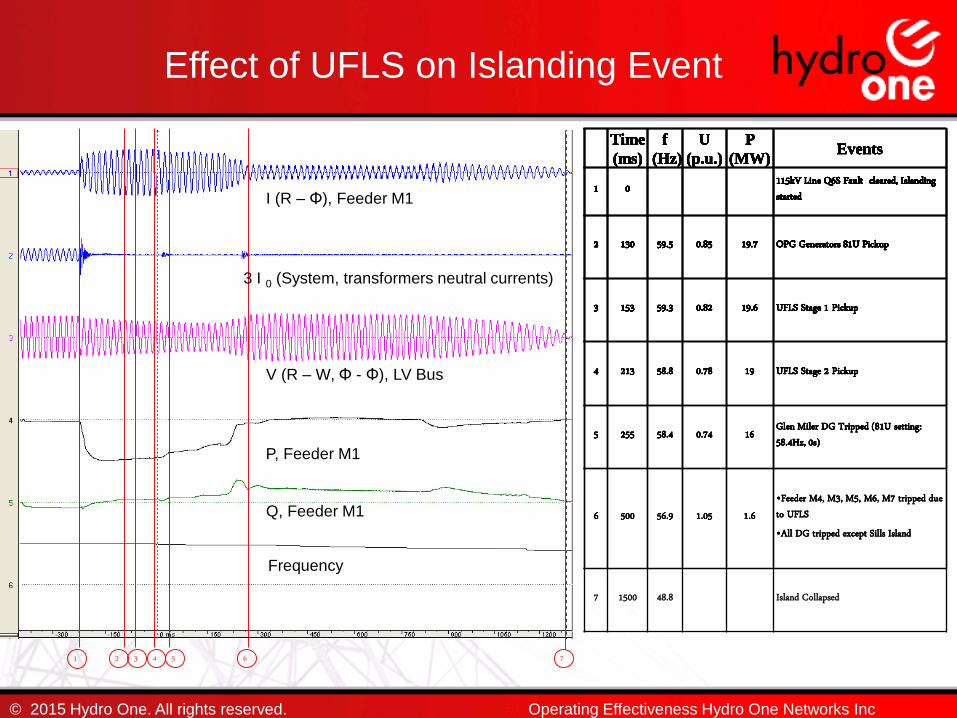
1 2 3 4 5 6 7
© 2015 Hydro One. All rights reserved.
Time
(ms)
f
(Hz)
U
(p.u.)
P
(MW)Events
1 0 115kV Line Q6S Fault cleared, Islanding started
Time
(ms)
f
(Hz)
U
(p.u.)
P
(MW)Events
1 0 115kV Line Q6S Fault cleared, Islanding started
2 130 59.5 0.85 19.7 OPG Generators 81U Pickup
Time
(ms)
f
(Hz)
U
(p.u.)
P
(MW)Events
1 0 115kV Line Q6S Fault cleared, Islanding started
2 130 59.5 0.85 19.7 OPG Generators 81U Pickup
3 153 59.3 0.82 19.6 UFLS Stage 1 Pickup
Time
(ms)
f
(Hz)
U
(p.u.)
P
(MW)Events
1 0 115kV Line Q6S Fault cleared, Islanding started
2 130 59.5 0.85 19.7 OPG Generators 81U Pickup
3 153 59.3 0.82 19.6 UFLS Stage 1 Pickup
4 213 58.8 0.78 19 UFLS Stage 2 Pickup
Time
(ms)
f
(Hz)
U
(p.u.)
P
(MW)Events
1 0 115kV Line Q6S Fault cleared, Islanding started
2 130 59.5 0.85 19.7 OPG Generators 81U Pickup
3 153 59.3 0.82 19.6 UFLS Stage 1 Pickup
4 213 58.8 0.78 19 UFLS Stage 2 Pickup
5 255 58.4 0.74 16 Glen Miler DG Tripped (81U setting: 58.4Hz, 0s)
Time
(ms)
f
(Hz)
U
(p.u.)
P
(MW)Events
1 0 115kV Line Q6S Fault cleared, Islanding started
2 130 59.5 0.85 19.7 OPG Generators 81U Pickup
3 153 59.3 0.82 19.6 UFLS Stage 1 Pickup
4 213 58.8 0.78 19 UFLS Stage 2 Pickup
5 255 58.4 0.74 16 Glen Miler DG Tripped (81U setting: 58.4Hz, 0s)
6 500 56.9 1.05 1.6•Feeder M4, M3, M5, M6, M7 tripped due to UFLS•All DG tripped except Sills Island
Time
(ms)
f
(Hz) (p.u.)
P
(MW)Events
1 0 115kV Line Q6S Fault cleared, Islanding started
2 130 59.5 0.85 19.7 OPG Generators 81U Pickup
3 153 59.3 0.82 19.6 UFLS Stage 1 Pickup
4 213 58.8 0.78 19 UFLS Stage 2 Pickup
5 255 58.4 0.74 16 Glen Miler DG Tripped (81U setting: 58.4Hz, 0s)
6 500 56.9 1.05 1.6•Feeder M4, M3, M5, M6, M7 tripped due to UFLS•All DG tripped except Sills Island
7 1500 48.8 Island Collapsed
Effect of UFLS on Islanding Event
Operating Effectiveness Hydro One Networks Inc
I (R – Φ), Feeder M1
3 I 0 (System, transformers neutral currents)
V (R – W, Φ - Φ), LV Bus
Frequency
P, Feeder M1
Q, Feeder M1

Identify P&C upgrades at Tx and Dx
Detailed P&C assessment should be carried out
Adequate feeder characteristics must be provided to customer to determine relay settings at DG end
DG inter-tie protection design and relay setting must be reviewed for acceptance
Change controls
Feeder Model & Configuration, Short circuit levels and DG equipment changes etc.
© 2015 Hydro One. All rights reserved. Operating Effectiveness Hydro One Networks Inc
SUMMARY and Important Points

Challenges in DG protections relay settings
Depending upon DG type/locations – feeder faults may not be visible to DG protections, issues with O/C & Distance Protection
DG protections have inherent disadvantages
Difficult trade off between DG protection sensitivity and selective – may suffer high number of nuisance trips
Utility feeder protections have advantages
Sensitive, Selective and Deterministic
Advantages of Transfer Trip and Adaptive Relaying to improve DG availability when not required to trip and ensure effective tripping of DGs when required to trip.
© 2015 Hydro One. All rights reserved.
SUMMARY and Important Points
Operating Effectiveness Hydro One Networks Inc
Thank You
© 2015 Hydro One. All rights reserved.
follow-up questions:[email protected] 345 5159 (Tel)416 587 3792 (Mobile)
Operating Effectiveness Hydro One Networks Inc

© 2015 Hydro One. All rights reserved.
The purpose of this presentation is to provide information about some of the issues that Hydro One Networks Inc. (“Hydro One”) has encountered during the process of connection generation facilities to Hydro One’s distribution system. The particular concerns that must be addressed by a generation proponent in respect of the connection of its generation facility to Hydro One’s distribution system will be set out in the Connection Impact Assessment that Hydro One performs or has performed, as the case may be, for such proposed connections and this presentation is not intended to amend, modify or replace same. Hydro One will not be liable or be responsible for any consequences of the use or reliance on the information contained in this presentation.
DISCLAIMER
Operating Effectiveness Hydro One Networks Inc