protection from high energy impacts using reinforced soil ...alpigeo.it/papers/protection.pdf ·...
TRANSCRIPT
Proceedings of the Second World Landslide Forum – 3-7 October 2011, Rome
Alberto Grimod (1) , Giorgio Giacchetti (2)
Protection from high energy impacts using reinforced soil embankments: design and experiences
(1) Alpigeo Consultant, Belluno, Via Barozzi 45, +39 328 0280835 (2) Maccaferri Technical Dept., Bologna, Italy
Abstract It is nowadays evident the remarkable increase of natural events such as landslides and rock falls. This paper describes and shows how the ground reinforced soil embankments represent an efficient solution for the mitigation of the rockfall related damage. The advantages of these types of construction are that they can resist multiple impacts and their downslope deformation is negligible. This means they can safely be placed close to infrastructure and moreover, they are environmental friendly. In the last few years the Polytechnic of Turin and Officine Maccaferri S.p.A. has developed a new approach to design reinforced soil embankments used for rockfall applications. This approach is based on FEM modelling, full-scale tests results and real experiences utilized to validate the numerical analysis and modelling.
Keywords rockfall, rockfall embankment, high energy impact.
Preliminary remarks Rockfall embankments are commonly used to stop high energy rockfall phenomena which could damage infrastructures, buildings, inhabited areas, etc.
The embankments built all around the world are made in different ways: by the simple compaction of soil, from gabions, from huge stones, but by far the most effective and reliable method is using reinforced soil, which represent a very good solution from both technical and economical point of view.
In spite of the large amount of installations already made, only in the last few years a new approach has been established to design these reinforced soil embankments using the ultimate limit state and the serviceability limit state philosophy.
This paper will analyse this new design method in order to define the most suitable geometry for a reinforced soil structure based on the energy and the trajectory parameters of the falling rocks.
Reinforced soil embankments The rockfall embankments are made as ordinary reinforced soil structures (RSS).
From a geotechnical point of view RSSs are composed of soil and reinforcing elements which help to distribute tensile stresses. These reinforcements are normally located horizontally during the installation phases, and they are wrapped at the edges of the structure to enclose layers of soil. The soil is compacted in layers of nominal 300-350 mm thickness.
In this way, the stresses on the RSS, due to the increasing of loads, are absorbed by the tensile strength of the reinforcements which are mobilized through the friction with the soil. At the same time, the compacted soil can resist to the compression stresses linked the vertical loads. Rockfall embankments are bi-facial reinforced soil structures with a vegetative or a gabion external facing. Table 1 Type of reinforces used on the RSS.
Reinforce name Typical tensile strength Picture
Geogrid up to 1300 kN/m
Geotextile up to 250 kN/m
Double twist wire mesh up to 60 kN/m
The most important advantages associated with reinforced soil embankments, are listed below:
1. the foundation surface is reduced because the facade inclination increases from 30°-40° to 65°-90°;
2. the amount of soil necessary to build the reinforced embankment is around 2-2.5 times less than the volume used for normal soil embankment;
3. the risk that a boulder overcomes the embankment after the impact is reduced
A. Grimod, G. Giacchetti – Design of reinforced soil rockfall embankments
2
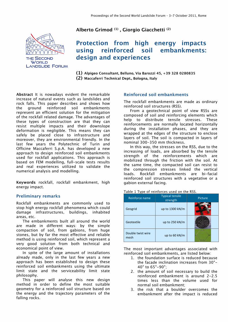
because of the high inclination of the mountain side facing, as shown in Fig. 2
Figure 1 The block has not enough rotational energy to overcome the embankment because reinforced embankments have 65°-90° mountain side face inclination (Oggeri et al., 2004). The researches Polytechnic of Turin, supported by Officine Maccaferri S.p.A., has developed a simple design procedure to size the geometry of the rockfall embankments.
This method is based on a research that, by utilizing full-scale tests, numerical modelling using the Finite Element Method (FEM), and real case histories, is able to give a tool that can be easily used by the designer of these structures as a guide line.
The full-scale tests were carried out by crashing concrete blocks, with variable mass (from 5,000 to 8,700 kg) and a speed, measured at the impact time, of 31 m/s, against embankments built by sand and gravel and reinforced with polymeric geogrids (Peila et al., 1998; Peila and Oggeri, 2006).
The dimensions of the tested ground reinforced embankments were: height = 4.2 m, base foundation = 5.0 m, facing inclination = 67° and geogrids vertical distance = 0.60 m.
Figure 2 Effect on downslope side of the reinforced embankment impacted during full-scale tests (Peila et al., 2007; Oggeri et al., 2004).
These tests have shown that the impact of a block produces two main effects on the structure: the creation of a hole in the upslope side, and the sliding on the downslope side of the strata, defined by the geogrids located close to the impact point. Table 2 shows the summary of the results of the full-scale tests:
Table 2 Full-scale test results (Ronco et al., 2009).
Test Impact energy
Number of
impacts
Upslope max displacement
Downslope max
displacement Test 1 2,500 kJ 1 0.60 m 0.17 m
Test 2 4,500 kJ 3 0.95 m 1.30 m
Collapse
0.80 m 1.20 m -‐
The numerical analyses are used to know and to predict the behaviour of the impacted embankments in a more economical way compared to the full-scale tests.
They have been done, by the Polytechnic of Turin, with a commercial code (ABACUS/Explicit), which use a 3D Finite Element Method (F.E.M.) based on the “central difference method” algorithm. With this tool all the dynamics aspects of the rock impact and their consequence on structures have been considered.
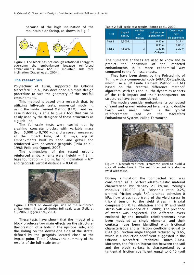
The models consider embankments composed of sand and gravel reinforced by a metallic double twist wire mesh, which is the typical reinforcement used on the Maccaferri Embankment System, called Terramesh.
Figure 3 Maccaferri Green Terramesh used to build a rockfall embankment. The reinforcement is a double twist wire mesh.
During simulation the compacted soil was considered as a perfect elasto-plastic material characterised by: density 21 kN/m3, Young’s modulus 110,000 kPa, Poisson’s ratio 0.25, drained friction angle 34°, drained cohesion 0 kPa, flow stress ratio (ratio of the yield stress in triaxial tension to the yield stress in triaxial compression) 0.78, dilatation angle 0° and yield stress 540 kPa (Ronco et al. 2009). The presence of water was neglected. The different layers enclosed by the metallic reinforcements have been modelled as single elements, and their contacts have been identified with frictional characteristics and a friction coefficient equal to 0.44 (soil friction angle tangent reduced by 0.65, which is a reduction coefficient suggested in the Officine Maccaferri technical notes-2005). Moreover, the friction interaction between the soil and the block surface is characterized by a tangential friction coefficient equal to 0.40 (soil
A. Grimod, G. Giacchetti – Design of reinforced soil rockfall embankments
3
friction angle tangent reduced in a parametric way).
The simulations consider an embankment (height = 6 m, foundation width = 6.30 m, facing inclination = 67°-70°, distance between the reinforcements = 75 cm) impacted by a cubic mass which develops 5,400 kJ kinetic energy (mass = 12,000 kg; speed = 30 m/s) at 1.20 m from the toe of the structure.
Figure 4 Model of the impact against the rockfall embankment made with double twist wire mesh reinforcements (Oggeri et al., 2009)
Figure 5 Contours plot of the numerical analysis made on a Green Terramesh embankment (Oggeri et al., 2009) F.E.M. modelling results show that the impact consequences are limited only on the layers directly involved in the impact, as already observed in the full-scale tests.
The internal embankment area influenced by the block impact is defined by the type of reinforcement. A truncated cone shape is observable and it is planimetrycally constituted by an inclination angle ψ, of around 45°.
Figure 6 Contour plot of the embankment area involved in the impact (plan view) (Oggeri et al., 2009).
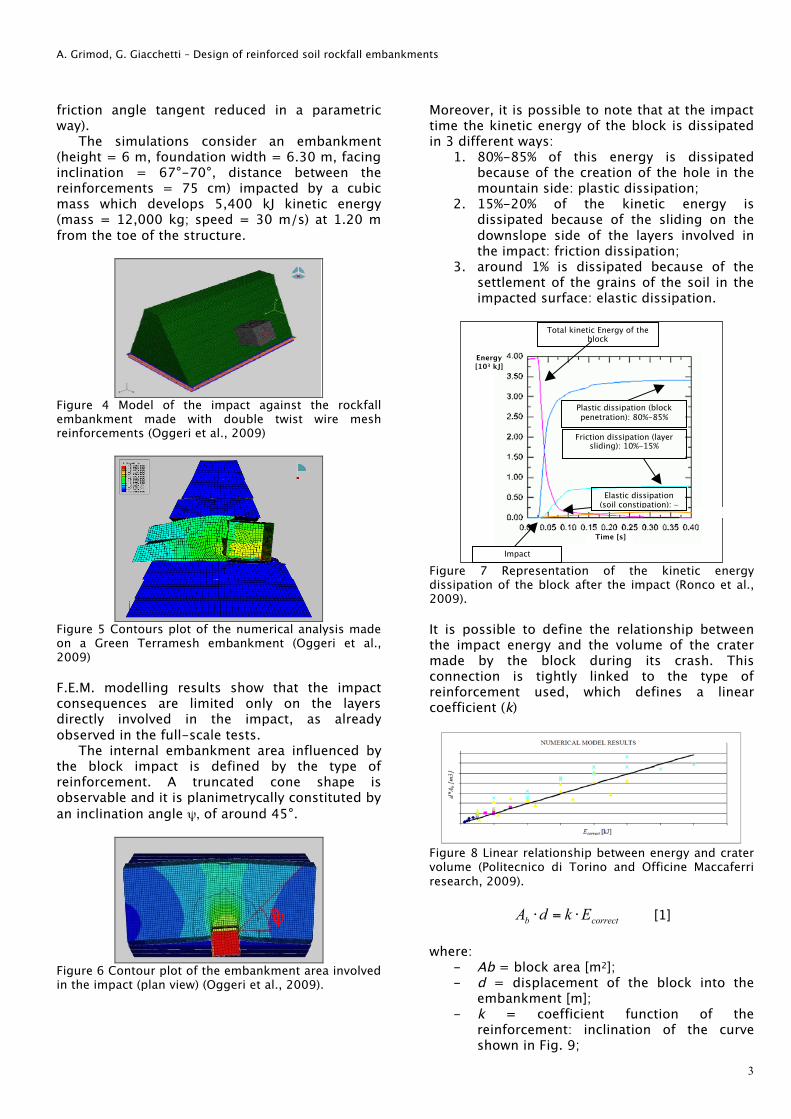
Moreover, it is possible to note that at the impact time the kinetic energy of the block is dissipated in 3 different ways:
1. 80%-85% of this energy is dissipated because of the creation of the hole in the mountain side: plastic dissipation;
2. 15%-20% of the kinetic energy is dissipated because of the sliding on the downslope side of the layers involved in the impact: friction dissipation;
3. around 1% is dissipated because of the settlement of the grains of the soil in the impacted surface: elastic dissipation.
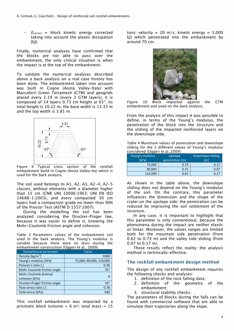
Figure 7 Representation of the kinetic energy dissipation of the block after the impact (Ronco et al., 2009). It is possible to define the relationship between the impact energy and the volume of the crater made by the block during its crash. This connection is tightly linked to the type of reinforcement used, which defines a linear coefficient (k)
Figure 8 Linear relationship between energy and crater volume (Politecnico di Torino and Officine Maccaferri research, 2009).
correctb EkdA !=! [1] where:
- Ab = block area [m2]; - d = displacement of the block into the
embankment [m]; - k = coefficient function of the
reinforcement: inclination of the curve shown in Fig. 9;
Impact
Total kinetic Energy of the block
Plastic dissipation (block penetration): 80%-85%
Friction dissipation (layer sliding): 10%-15%
Energy [103 kJ]
Time [s]
Elastic dissipation (soil constipation): ~
ψψ
A. Grimod, G. Giacchetti – Design of reinforced soil rockfall embankments
4
- Ecorrect = block kinetic energy corrected taking into account the plastic dissipation [kJ].
Finally, numerical analyses have confirmed that the blocks are not able to pass over the embankment, the only critical situation is when the impact is at the top of the embankment. To validate the numerical analyses described above a back analysis on a real case history has been done. The embankment taken into account was built in Cogne (Aosta Valley-Italy) with Maccaferri Green Terramesh (GTM) and geogrids placed every 2.19 m (every 3 GTM layers), it is composed of 14 layers 0.73 cm height at 65°; its total height is 10.22 m, the base width is 13.33 m and the top width is 3.81 m.
Figure 9 Typical cross section of the rockfall embankment build in Cogne (Aosta Valley-Ita) which is used for the back analysis. The soil used belongs to A1, A2, A3, A2-4, A2-5 classes, without elements with a diameter higher than 15 cm (CNR UNI 10006:1963; UNI EN ISO 14688-1:2003), and every compacted 30 cm layers had a compaction grade no lower than 90% of the Proctor Test (ASTM D 1557:2007).
During the modelling the soil has been analyzed considering the Drucker-Prager law, because it was easier to define it, knowing the Mohr-Coulomb friction angle and cohesion. Table 3 Parameters values of the embankment soil used in the back analysis. The Young’s modulus is variable because there were no tests during the embankment construction (Oggeri et al., 2009)
Geotechnical parameter Value Density [kg/m3] 1900 Young’s modulus [kPa] 75,000; 90,000; 110,000 Poisson’s ratio [-‐] 0.30 Mohr-‐Coulomb friction angle 35° Mohr-‐Coulomb drained cohesion [kPa] 0
Drucker-‐Prager friction angle 55° Flow stress ratio [-‐] 0.78 Yield stress [kPa] 540
This rockfall embankment was impacted by a prismatic block (volume = 6 m3; total mass = 15
tons; velocity = 20 m/s; kinetic energy = 3,000 kJ) which penetrated into the embankment by around 70 cm.
Figure 10 Block impacted against the GTM embankment and used on the back analysis.
From the analysis of this impact it was possible to define, in terms of the Young’s modulus, the penetration of the block into the structure and the sliding of the impacted reinforced layers on the downslope side. Table 4 Maximum values of penetration and downslope sliding for the 3 different values of Young’s modulus considered (Oggeri et al.,2009).
Young’s modulus [kPa]
Upslope penetration [m]
Downslope sliding [m]
75,000 0.74 0.17 90,000 0.71 0.07
110,000 0.62 0.17 As shown in the table above, the downslope sliding does not depend on the Young’s modulus of the soil. On the contrary, this parameter influences the dimension and the shape of the crater on the upslope side: the penetration can be reduced by improving the soil settlement of the structure.
In any case, it is important to highlight that this parameter is only conventional, because the phenomena during the impact are neither elastic or linear. Moreover, the values ranges are limited both for the mountain side penetration (from 0.62 to 0.74 m) and the valley side sliding (from 0.07 to 0.17 m).
These results reflect the reality: the analysis method is technically-effective. The rockfall embankment design method The design of any rockfall embankment requires the following checks and analyses:
1. definition of the rock falling data; 2. definition of the geometry of the
embankment; 3. structural stability checks.
The parameters of blocks during the falls can be found with commercial software that are able to simulate their trajectories along the slope.
A. Grimod, G. Giacchetti – Design of reinforced soil rockfall embankments
5
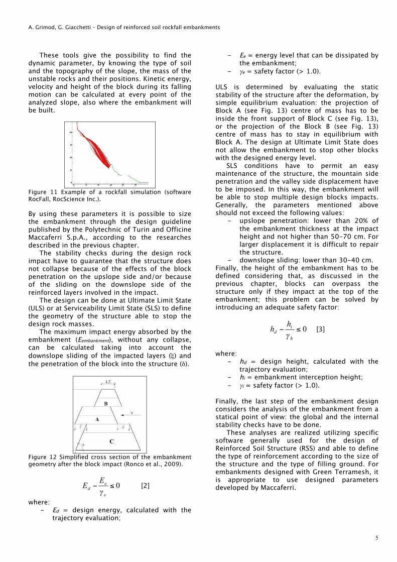
These tools give the possibility to find the dynamic parameter, by knowing the type of soil and the topography of the slope, the mass of the unstable rocks and their positions. Kinetic energy, velocity and height of the block during its falling motion can be calculated at every point of the analyzed slope, also where the embankment will be built.
Figure 11 Example of a rockfall simulation (software RocFall, RocScience Inc.). By using these parameters it is possible to size the embankment through the design guideline published by the Polytechnic of Turin and Officine Maccaferri S.p.A., according to the researches described in the previous chapter.
The stability checks during the design rock impact have to guarantee that the structure does not collapse because of the effects of the block penetration on the upslope side and/or because of the sliding on the downslope side of the reinforced layers involved in the impact.
The design can be done at Ultimate Limit State (ULS) or at Serviceability Limit State (SLS) to define the geometry of the structure able to stop the design rock masses.
The maximum impact energy absorbed by the embankment (Eembankment), without any collapse, can be calculated taking into account the downslope sliding of the impacted layers (ξ) and the penetration of the block into the structure (δ).
Figure 12 Simplified cross section of the embankment geometry after the block impact (Ronco et al., 2009).
0!"e
edEE#
[2]
where: - Ed = design energy, calculated with the
trajectory evaluation;
- Ee = energy level that can be dissipated by the embankment;
- γe = safety factor (> 1.0).
ULS is determined by evaluating the static stability of the structure after the deformation, by simple equilibrium evaluation: the projection of Block A (see Fig. 13) centre of mass has to be inside the front support of Block C (see Fig. 13), or the projection of the Block B (see Fig. 13) centre of mass has to stay in equilibrium with Block A. The design at Ultimate Limit State does not allow the embankment to stop other blocks with the designed energy level.
SLS conditions have to permit an easy maintenance of the structure, the mountain side penetration and the valley side displacement have to be imposed. In this way, the embankment will be able to stop multiple design blocks impacts. Generally, the parameters mentioned above should not exceed the following values:
- upslope penetration: lower than 20% of the embankment thickness at the impact height and not higher than 50-70 cm. For larger displacement it is difficult to repair the structure.
- downslope sliding: lower than 30-40 cm. Finally, the height of the embankment has to be defined considering that, as discussed in the previous chapter, blocks can overpass the structure only if they impact at the top of the embankment; this problem can be solved by introducing an adequate safety factor:
0!"h
id
hh#
[3]
where:
- hd = design height, calculated with the trajectory evaluation;
- hi = embankment interception height; - γi = safety factor (> 1.0).
Finally, the last step of the embankment design considers the analysis of the embankment from a statical point of view: the global and the internal stability checks have to be done.
These analyses are realized utilizing specific software generally used for the design of Reinforced Soil Structure (RSS) and able to define the type of reinforcement according to the size of the structure and the type of filling ground. For embankments designed with Green Terramesh, it is appropriate to use designed parameters developed by Maccaferri.
C
A. Grimod, G. Giacchetti – Design of reinforced soil rockfall embankments
6
Figure 13 Internal and Global stability check of the embankment (software MacStaRS W, Maccaferri).
These checks verify, both in the static and seismic conditions, that the designed structure is stable (Fig. 14) and it does not provoke negatives effects on the global stability of the entire slope (Fig. 15) which is overloaded by a new load. Experience – Cogne Case History The 5th June 2007 large blocks (larger than 30 m3) impacted on the regional road Aymavilles-Cogne (SR 47) in locality Pont Laval. The road was closed, and the town of Cogne was isolated for few days.
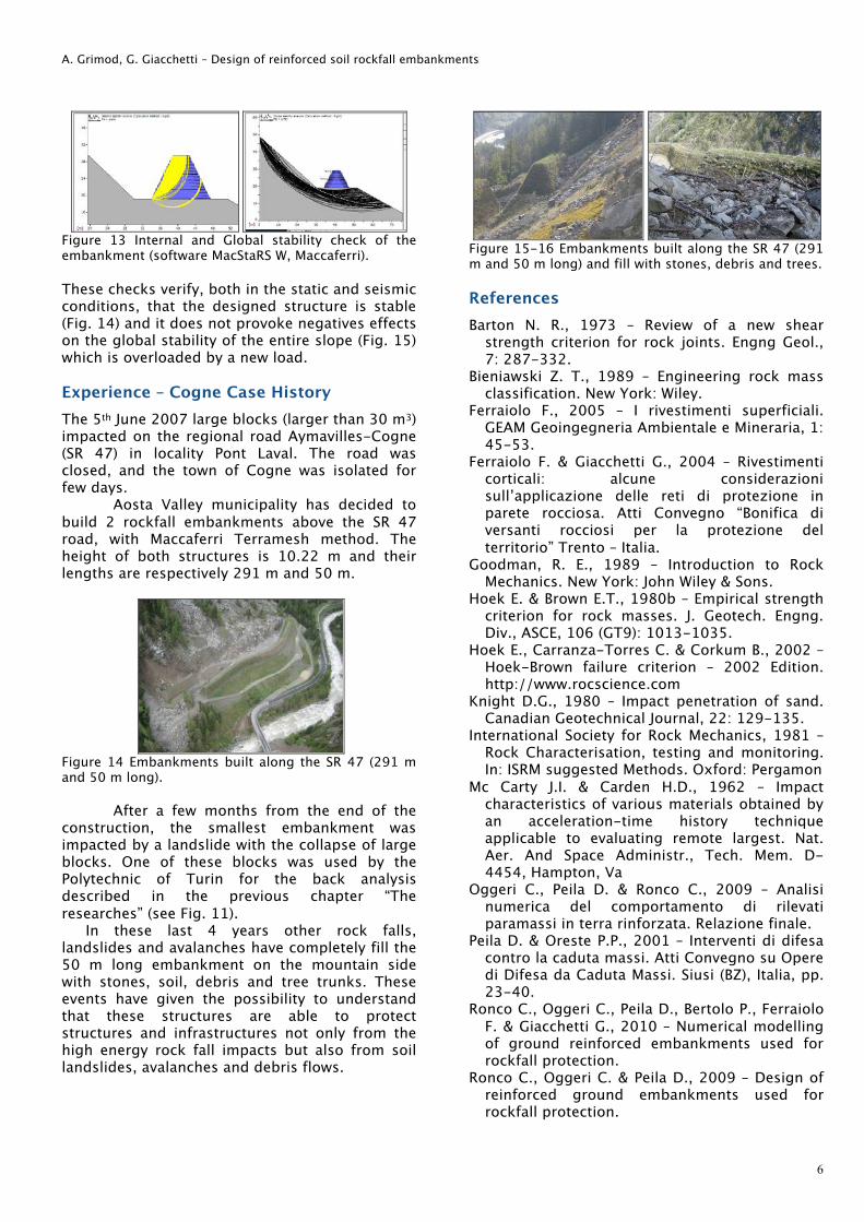
Aosta Valley municipality has decided to build 2 rockfall embankments above the SR 47 road, with Maccaferri Terramesh method. The height of both structures is 10.22 m and their lengths are respectively 291 m and 50 m.
Figure 14 Embankments built along the SR 47 (291 m and 50 m long).
After a few months from the end of the construction, the smallest embankment was impacted by a landslide with the collapse of large blocks. One of these blocks was used by the Polytechnic of Turin for the back analysis described in the previous chapter “The researches” (see Fig. 11).
In these last 4 years other rock falls, landslides and avalanches have completely fill the 50 m long embankment on the mountain side with stones, soil, debris and tree trunks. These events have given the possibility to understand that these structures are able to protect structures and infrastructures not only from the high energy rock fall impacts but also from soil landslides, avalanches and debris flows.
Figure 15-16 Embankments built along the SR 47 (291 m and 50 m long) and fill with stones, debris and trees. References Barton N. R., 1973 – Review of a new shear
strength criterion for rock joints. Engng Geol., 7: 287-332.
Bieniawski Z. T., 1989 – Engineering rock mass classification. New York: Wiley.
Ferraiolo F., 2005 – I rivestimenti superficiali. GEAM Geoingegneria Ambientale e Mineraria, 1: 45-53.
Ferraiolo F. & Giacchetti G., 2004 – Rivestimenti corticali: alcune considerazioni sull’applicazione delle reti di protezione in parete rocciosa. Atti Convegno “Bonifica di versanti rocciosi per la protezione del territorio” Trento – Italia.
Goodman, R. E., 1989 – Introduction to Rock Mechanics. New York: John Wiley & Sons.
Hoek E. & Brown E.T., 1980b – Empirical strength criterion for rock masses. J. Geotech. Engng. Div., ASCE, 106 (GT9): 1013-1035.
Hoek E., Carranza-Torres C. & Corkum B., 2002 – Hoek-Brown failure criterion – 2002 Edition. http://www.rocscience.com
Knight D.G., 1980 – Impact penetration of sand. Canadian Geotechnical Journal, 22: 129-135.
International Society for Rock Mechanics, 1981 – Rock Characterisation, testing and monitoring. In: ISRM suggested Methods. Oxford: Pergamon
Mc Carty J.I. & Carden H.D., 1962 – Impact characteristics of various materials obtained by an acceleration-time history technique applicable to evaluating remote largest. Nat. Aer. And Space Administr., Tech. Mem. D-4454, Hampton, Va
Oggeri C., Peila D. & Ronco C., 2009 – Analisi numerica del comportamento di rilevati paramassi in terra rinforzata. Relazione finale.
Peila D. & Oreste P.P., 2001 – Interventi di difesa contro la caduta massi. Atti Convegno su Opere di Difesa da Caduta Massi. Siusi (BZ), Italia, pp. 23-40.
Ronco C., Oggeri C., Peila D., Bertolo P., Ferraiolo F. & Giacchetti G., 2010 – Numerical modelling of ground reinforced embankments used for rockfall protection.
Ronco C., Oggeri C. & Peila D., 2009 – Design of reinforced ground embankments used for rockfall protection.