protection testing- a journey through time · protection testing- a journey ... it was composed of...
TRANSCRIPT

Testing of devices, distributed functions and systems
Protection Testing- A Journey through Time
Walter Schossig, VDE Thüringen/ Thomas Schossig, OMICRON electronics GmbH [email protected] / [email protected]
Germany/ Austria
Introduction
The first protection devices appeared at the same time as the first installations for electrical power generation and transmission. Soon, responsible plant managers realized that executing a thoroughly test before commissioning and during operation could prevent failures and ensure reliable power supply. The first testing method which consisted of monitoring the behavior of the protection devices during power system failures was soon replaced by the method of supplying the relays with current and voltage quantities obtained using regulating transformers or regulating resistors, and measuring the corresponding trip time of the protection devices. Assembly and disassembly of the testing and measuring equipment always took a long time. This article shows the way from portable test sets to intelligent testing equipment and the simultaneous development of the testing technology in the form of a time travel.
First steps of monitoring and testing methods
The first manufacturers of electrical installations were very concerned about achieving and maintaining sufficient insulation. The first test device consisting of a small magneto-inductor was designed in 1886 by Siemens & Halske (S&H) (Fig. 1) [1]. This device was powered by a hand crank and contained a galvanometer the scale of which was already graduated in ohms.
Fig. 1 Insulation tester, S&H, 1886
In 1899, Wilkens and Benischke (AEG) developed the insulation resistance meter for AC installations [2]. They achieved the sensitivity required to measure resistances of up to 1 MΩ by using an induction measuring element which worked in the same way as a separately excited dynamo. With the production of protection relays at the beginning of the past century, it was recognized that owing to the great importance of tripping devices and relays as protection elements in the whole power system, it was not only necessary to thoroughly test the protection devices at the manufacturer prior to delivery but also to continuously monitor and test these devices during operation. Thus, plant managers considered it as particularly advantageous that the driving mechanism of the BBC reactance relay (Fig. 2) just had a runtime of approx. 100 seconds, which corresponded on average to approx. 50 operating cycles. After this, the mechanism had to be wound by hand which implied regular relay checks.

Fig. 2 Reactance relay with hand-wound mechanical driving mechanism, BBC, 1928
Here is an extract of the Austrian professional journal Elektrotechnik und Maschinenbau [3] (Electrical and mechanical engineering) published in 1926: "Monitoring and maintenance of the protection installation is usually performed by a monitoring group consisting of at least two persons. This group regularly tests all transformers and relays as well as their interaction with the help of a specific current transformer (relay testing equipment). Since it is not possible to visually inspect the transformers, relays and connecting cables, there is no guarantee that the devices are still intact between two checks carried out in intervals of approximately one year. Consequently, protection can never be trusted. This incertitude is considered as a general weak point of all relay installations. The elimination of this incertitude would require that the installation is not only operational in case of failure, but continuously in service to a certain extent instead. This could occur in the following way: 1. Designing the relay as measuring instrument with pointer, i.e., as contact voltmeter, contact ammeter, etc. During normal operation, the pointer should point to a certain value corresponding to the measuring instruments on the switchboard. If this is the case, the current and voltage transformers, the connection cables and the current and voltage systems of the relays are ok. 2. Installation of glow lamps or lamps with a power consumption below the value required for tripping, connected in parallel to the trip contacts. If these lamps glow, there is no interruption in the tripping circuit, neither in the cable nor in the coil. 3. Installation of a test lever that causes compulsory contact making by directly moving the pointer against the contact or, for example in case of an overvoltage relay, by short-circuiting a part of the series resistor resulting in a pick-up. If the oil circuit breaker cannot be tripped for this check, it is necessary to make sure that the trip coil picks up but does not trip by installing a lock during the test (if possible at a visible place so that you cannot forget to remove it after the test)." The first measure enables to monitor the AC side and the last measure the DC side. This check could be carried out very easily by the switching engineer every week, the observation of the relay scales and glow lamps every day and even during each tour of inspection and of course during switching operations. For distance protection, the resistance-dependant runtime had to be checked. For this purpose, a regulating resistor was connected in series to the voltage coil and then adjusted manually until the relay picked up. Each position of the resistor had a certain voltage value assigned. By comparing the voltage read on the resistor with the actual voltage on the station it was possible to determine whether the relay and its transformers worked properly regarding the AC side. The regulating resistor had to be equipped with a spring that led the actuating mechanism back to its neutral position when releasing the grip because it was frequent to forget to put it back. It was also possible to deliberately interrupt the pick-up by removing the resistor contact from its neutral position. [3] In order to localize faults or even to connect testing equipment, it was necessary to disconnect wires, which was very time consuming and always held the risk of mixing up wires. It was thus proposed to use "terminal boards" [3].
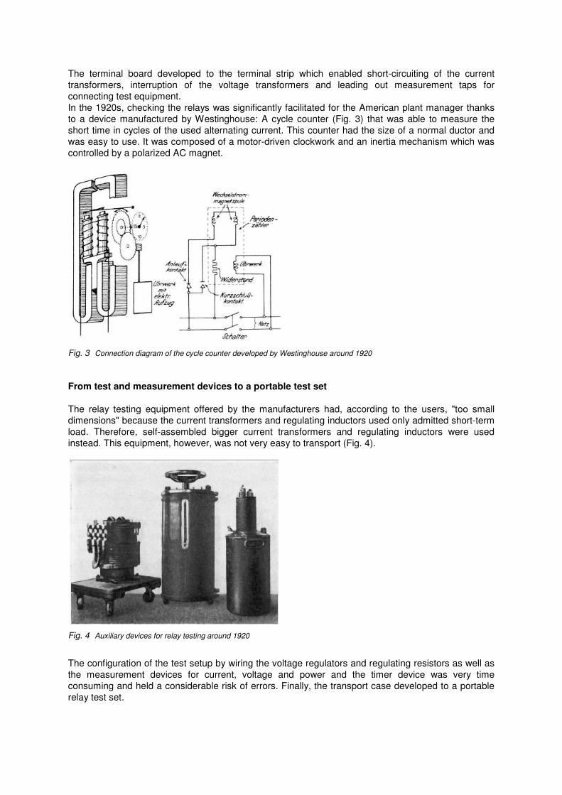
The terminal board developed to the terminal strip which enabled short-circuiting of the current transformers, interruption of the voltage transformers and leading out measurement taps for connecting test equipment. In the 1920s, checking the relays was significantly facilitated for the American plant manager thanks to a device manufactured by Westinghouse: A cycle counter (Fig. 3) that was able to measure the short time in cycles of the used alternating current. This counter had the size of a normal ductor and was easy to use. It was composed of a motor-driven clockwork and an inertia mechanism which was controlled by a polarized AC magnet.
Fig. 3 Connection diagram of the cycle counter developed by Westinghouse around 1920
From test and measurement devices to a portable test set
The relay testing equipment offered by the manufacturers had, according to the users, "too small dimensions" because the current transformers and regulating inductors used only admitted short-term load. Therefore, self-assembled bigger current transformers and regulating inductors were used instead. This equipment, however, was not very easy to transport (Fig. 4).
Fig. 4 Auxiliary devices for relay testing around 1920
The configuration of the test setup by wiring the voltage regulators and regulating resistors as well as the measurement devices for current, voltage and power and the timer device was very time consuming and held a considerable risk of errors. Finally, the transport case developed to a portable relay test set.

Fig. 5 shows the relay testing equipment contained in a case, manufactured in the 1920s by V&H, including necessary utilities.
Fig. 5 Portable case with relay testing equipment, manufactured by V&H around 1925
Distance protection and directional relay test equipment was manufactured by Dr. Paul Mayer AG, consisting of a calibration table, a high current transformer, a phase shifter and a current regulator. Great importance was also attached to the correct transmission behavior of the instrument transformers. The differences between the secondary currents or voltages of the unit under test and those of a standard transformer with the same ratio were measured according to the null method using the portable instrument transformer testing equipment developed by Dr. Hohle. Fig. 6 shows the transportable transformer test set from 1931. The unit under test and the standard had to have the same ratio so that the standard had to provide splitting according to the measurement ranges.
Fig. 6 Transportable transformer test set up to 2500/5 A, Siemens, 1931
In order to test the function of the whole protection system, the aim was to achieve complete primary testing.

In the 1930s and the following years, each relay manufacturer brought his own primary and secondary relay testing equipment on the market (Fig. 7).
Fig. 7 Three-phase secondary testing equipment for distance protection relays, AEG, 1937
In order to comply with the measuring devices decree which required that calibration had to be made every two years, measuring devices such as current, voltage and power meters as well as timers were mostly connected externally. Because of their weight, regulators, transformers, phase shifters, etc. often had to be placed in individual devices. It was mostly impossible to see externally if a power transformer had been damaged, for example if it had been automatically disconnected from the grid during a thunderstorm. Up to the end of the 1920s, the plant managers were confronted to the delicate issue and often momentous decision which consisted in determining whether the affected device could be switched on without being verified. At that time, the decision depended of the temperament and personality of the manager rather than of his technical skills. If he was careful, he decided to put the power transformer out of service, to open and then dismantle it. After two or three workdays, it might have been possible to see that the device was not damaged. Consequently, the time-consuming and cost-intensive revision was unnecessary and the power transformer could have been switched on directly. On the contrary, if the responsible was audacious and swashbuckling, he switched on the power transformer without previous testing. In this case, it could happen that the device exploded when switching on and then became completely unusable. By opening a valve it was possible to let the gas leak and determinate if it was flammable or not. These indications were a relatively reliable way to determine what had to happen with the power transformer. But the safe method consisted in installing a gas test set. With the help of the precipitate in the silver nitrate solution, it was possible to determine if only the air or a breakdown of the oil or an insulation failure was the cause of the pick-up of the Buchholz relay.

"Hot" Testing
Earth fault and short-circuit experiments were made in the 1920s particularly to test the influence of the arc resistance and the interaction of the distance protection devices of different manufacturers available in the power system. Thus, Bayernwerk carried out extensive short-circuit experiments with oscillographic recording in the 110 kV system in 1925/1926 together with S&H, AEG and BBC. In 1928, Thüringenwerk tested the Siemens-Westinghouse impedance relay (Fig. 8) with a total of 22 two- or three-pole short-circuits placed at different positions in the 50 kV power system.
Fig. 8 Short-circuit experiment in the 50 kV power system, Thüringenwerk, 1928
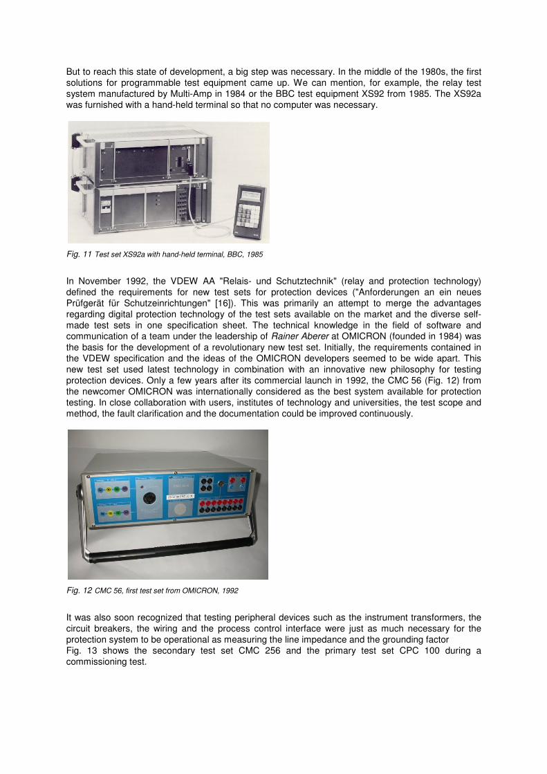
These experiments were very risky at that time, considering that, for example, switch-off times of up to 10 s were state of the art in 110 kV power systems. However, the future users and manufacturers attached again and again great importance to network experiments prior to the introduction of new protection generations and protection principles. Several manufacturers participated in these experiments and connected their devices into the secondary circuit. On the 23 October 1927, Max Buchholz carried out extensive experiments with the Buchholz relay (designed and manufactured by himself) for faults inside and outside power transformers as well as in bulk-oil circuit breakers [4]. To do this, the test stations located at power plant Borken were supplied via a 12.5 MVA power transformer with 60 kV or 5 kV, respectively. The power was generated in the power plant Hemfurth of the "Preußischen Kraftwerke Oberweser A.G." (5 generators with a total power of 15 MW) and transmitted via the 60 kV double wire line Hemfurth-Borken. A water resistor for 5 kV served as load.
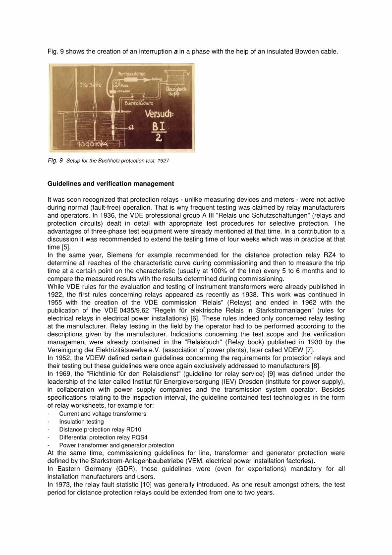
Fig. 9 shows the creation of an interruption a in a phase with the help of an insulated Bowden cable.
Fig. 9 Setup for the Buchholz protection test, 1927
Guidelines and verification management
It was soon recognized that protection relays - unlike measuring devices and meters - were not active during normal (fault-free) operation. That is why frequent testing was claimed by relay manufacturers and operators. In 1936, the VDE professional group A III "Relais und Schutzschaltungen" (relays and protection circuits) dealt in detail with appropriate test procedures for selective protection. The advantages of three-phase test equipment were already mentioned at that time. In a contribution to a discussion it was recommended to extend the testing time of four weeks which was in practice at that time [5]. In the same year, Siemens for example recommended for the distance protection relay RZ4 to determine all reaches of the characteristic curve during commissioning and then to measure the trip time at a certain point on the characteristic (usually at 100% of the line) every 5 to 6 months and to compare the measured results with the results determined during commissioning. While VDE rules for the evaluation and testing of instrument transformers were already published in 1922, the first rules concerning relays appeared as recently as 1938. This work was continued in 1955 with the creation of the VDE commission "Relais" (Relays) and ended in 1962 with the publication of the VDE 0435/9.62 "Regeln für elektrische Relais in Starkstromanlagen" (rules for electrical relays in electrical power installations) [6]. These rules indeed only concerned relay testing at the manufacturer. Relay testing in the field by the operator had to be performed according to the descriptions given by the manufacturer. Indications concerning the test scope and the verification management were already contained in the "Relaisbuch" (Relay book) published in 1930 by the Vereinigung der Elektrizitätswerke e.V. (association of power plants), later called VDEW [7]. In 1952, the VDEW defined certain guidelines concerning the requirements for protection relays and their testing but these guidelines were once again exclusively addressed to manufacturers [8]. In 1969, the "Richtlinie für den Relaisdienst" (guideline for relay service) [9] was defined under the leadership of the later called Institut für Energieversorgung (IEV) Dresden (institute for power supply), in collaboration with power supply companies and the transmission system operator. Besides specifications relating to the inspection interval, the guideline contained test technologies in the form of relay worksheets, for example for: Current and voltage transformers Insulation testing Distance protection relay RD10 Differential protection relay RQS4 Power transformer and generator protection At the same time, commissioning guidelines for line, transformer and generator protection were defined by the Starkstrom-Anlagenbaubetriebe (VEM, electrical power installation factories). In Eastern Germany (GDR), these guidelines were (even for exportations) mandatory for all installation manufacturers and users. In 1973, the relay fault statistic [10] was generally introduced. As one result amongst others, the test period for distance protection relays could be extended from one to two years.

A further step towards standardization of the protection systems was the introduction of test plug circuitry [11] for all secondary protection devices. To enable test execution during operation, an interim protection was connected between socket and relay. This definite-time overcurrent protection provided the line protection functionality during the test and had a time setting of max. 1 second in the medium-voltage system and 0.4 s in the 110 kV system. An important and informative technology was the introduction of the 380 V test for transformer differential protection. With the installation of a three-pole short-circuit on the low voltage side and the injection of low voltage on the high voltage side of the power transformer, the complete wiring and in particular the correct dimensioning and interconnection of the matching transformers required for the electromechanical and static protection could be tested by connecting 9 switchable ammeters (Fig. 10) .
Fig. 10 "Differential protection test case"
In the 1970s, differential protection systems were tested by gradually increasing the voltage of the generators and power transformers with high voltage levels of 110 kV and above. For this, it was necessary to connect a corresponding line system through on a length of sometimes up to 100 km, and to disable the protection elements on this line in order prevent unintentional interruption of the protection.
Steps towards digital testing
Digital protection relays were introduced at the end of the 1980s. The motto "set up a relay only
once and then forget it for the rest of its life" diffused at that time by the manufacturers soon turned out to be wrong. This was demonstrated by practical experience and the failure statistics introduced in Austria by the VEÖ-UA "Schutztechnik" (protection) in 1987 for static protection devices and in 1991 for numerical protection devices [12]. The VDEW AA "Relais und Schutztechnik" (relays and protection technology) developed the "Prüfempfehlungen für digitale Schutzeinrichtungen mit Selbstüberwachung" [13] (test recommendations for digital protection devices with auto-monitoring) in 1995 in collaboration with the relay manufacturers. These recommendations were the basis for the test methods and technologies developed at the transmission and distribution system operators (TSO and DSO). However, practice showed that there were considerable deviations in the scope of testing for commissioning and maintenance in the individual companies. The VDE/FNN-VEÖ guidelines "Digitale Schutzsysteme" (digital protection systems) [14] and "Leitfaden Schutztechnik" (guideline for protection) [15], both resulting from the collaboration of German and Austrian protection specialists, constituted a solid basis for the development of relay-specific test methods.
But to reach this state of development, a big step was necessary. In the middle of the 1980s, the first solutions for programmable test equipment came up. We can mention, for example, the relay test system manufactured by Multi-Amp in 1984 or the BBC test equipment XS92 from 1985. The XS92a was furnished with a hand-held terminal so that no computer was necessary.
Fig. 11 Test set XS92a with hand-held terminal, BBC, 1985
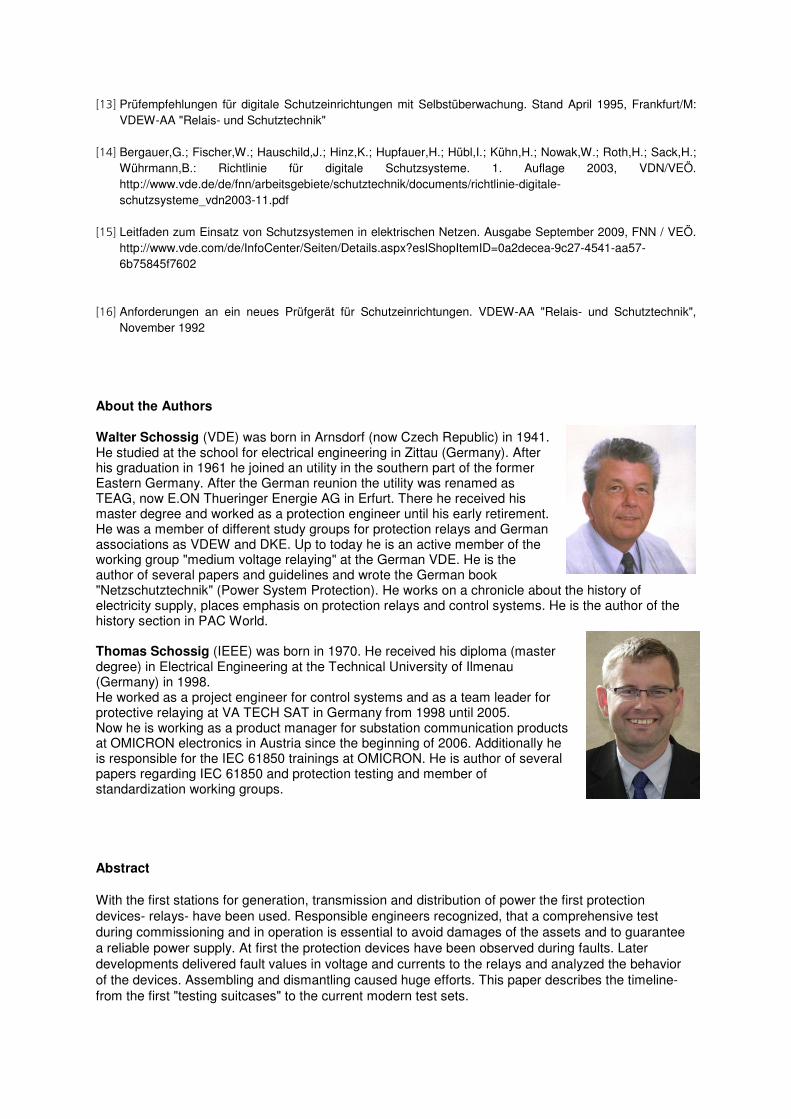
In November 1992, the VDEW AA "Relais- und Schutztechnik" (relay and protection technology) defined the requirements for new test sets for protection devices ("Anforderungen an ein neues Prüfgerät für Schutzeinrichtungen" [16]). This was primarily an attempt to merge the advantages regarding digital protection technology of the test sets available on the market and the diverse self-made test sets in one specification sheet. The technical knowledge in the field of software and communication of a team under the leadership of Rainer Aberer at OMICRON (founded in 1984) was the basis for the development of a revolutionary new test set. Initially, the requirements contained in the VDEW specification and the ideas of the OMICRON developers seemed to be wide apart. This new test set used latest technology in combination with an innovative new philosophy for testing protection devices. Only a few years after its commercial launch in 1992, the CMC 56 (Fig. 12) from the newcomer OMICRON was internationally considered as the best system available for protection testing. In close collaboration with users, institutes of technology and universities, the test scope and method, the fault clarification and the documentation could be improved continuously.
Fig. 12 CMC 56, first test set from OMICRON, 1992
It was also soon recognized that testing peripheral devices such as the instrument transformers, the circuit breakers, the wiring and the process control interface were just as much necessary for the protection system to be operational as measuring the line impedance and the grounding factor Fig. 13 shows the secondary test set CMC 256 and the primary test set CPC 100 during a commissioning test.

Fig. 13 Secondary test set CMC 256 and primary test set CPC
Literature
[1] Dettmar,G.: Die Entwicklung der Starkstromtechnik in Deutschland. Teil 1: Die Anfänge bis etwa 1890. Hrsg. VDE-Ausschuss "Geschichte der Elektrotechnik" Bd.
[2] Schweder,B.: Forschen und Schaffen. Beiträge der AEG zur Entwicklung der Elektrotechnik bis zum Wiederaufbau nach dem zweiten Weltkrieg. BandHrsg. AEG, Berlin 1965
[3] Arnold,R.: Der Relaisschutz von Großkraftanlagen.
[4] Buchholz,M.: Programm für die Versuche mit dem BuchholzAusgleichsgefäß, Schalter usw. am 23. Oktober 1927 beim Kraftwerk Borken der Gewerkschaft "Großkraftwerk Main-Weser" im Netz der PreußiPost G.m.b.H.
[5] Fachgruppe A III Relais und Schutzschaltungen. ETZ 57(1936)31,894
[6] Poßner,O.: Neue Relaisvorschriften. ETZ
[7] Relaisbuch. Herausgegeben von der Vereinigung der Elektrizitä
[8] VDEW-Ringbuch "Schutztechnik", VWEW
[9] Pech,H.: Richtlinie für den Relaisdienst. IEV, Dresden, BerichtBer.-Nr. 74-3223-(1991)FE
[10] Clemens,H.: Relaisfehlerstatistik in Verteilernetzen.
[11] Schossig,W.: Einsatz von Prüfsteckdosen für Netzwww.walter-schossig.de
[12] Fickert, L.: Auswertung der Fehlerstatistik numeriVEÖ-Journal 1-2/95,87-89
Secondary test set CMC 256 and primary test set CPC 100 from OMICRON in use
Dettmar,G.: Die Entwicklung der Starkstromtechnik in Deutschland. Teil 1: Die Anfänge bis etwa 1890. Hrsg. Ausschuss "Geschichte der Elektrotechnik" Bd. 8, Berlin; Offenbach: vde-verlag, 2.
hen und Schaffen. Beiträge der AEG zur Entwicklung der Elektrotechnik bis zum Wiederaufbau nach dem zweiten Weltkrieg. Band 1, 472 S.; Band 2, 472 S. u. Band
Arnold,R.: Der Relaisschutz von Großkraftanlagen. EuM (1926)51,927-938
Buchholz,M.: Programm für die Versuche mit dem Buchholz-Schutz für Transformatoren mit und ohne Ausgleichsgefäß, Schalter usw. am 23. Oktober 1927 beim Kraftwerk Borken der Gewerkschaft
Weser" im Netz der Preußischen Kraftwerke "Oberweser" Akt.
Fachgruppe A III Relais und Schutzschaltungen. ETZ 57(1936)31,894
Poßner,O.: Neue Relaisvorschriften. ETZ-B 24(1972)23,155-156
Relaisbuch. Herausgegeben von der Vereinigung der Elektrizitätswerke e.V., Berlin 1930
Ringbuch "Schutztechnik", VWEW
Pech,H.: Richtlinie für den Relaisdienst. IEV, Dresden, Bericht-Nr. 21/257/69 FE Überarbeitung: Knöfler,H.
Clemens,H.: Relaisfehlerstatistik in Verteilernetzen. Ber.-Nr.: 21/708/1973, IEV Dresden
Schossig,W.: Einsatz von Prüfsteckdosen für Netzschutzeinrichtungen. etz 123(2002)11/12,38
Fickert, L.: Auswertung der Fehlerstatistik numerischer Schutzeinrichtungen für die Jahre 1991 bis 1993,
Dettmar,G.: Die Entwicklung der Starkstromtechnik in Deutschland. Teil 1: Die Anfänge bis etwa 1890. Hrsg. verlag, 2. Aufl. 1989
hen und Schaffen. Beiträge der AEG zur Entwicklung der Elektrotechnik bis zum 3, 520 S., Berlin: 1965,
Schutz für Transformatoren mit und ohne Ausgleichsgefäß, Schalter usw. am 23. Oktober 1927 beim Kraftwerk Borken der Gewerkschaft
hen Kraftwerke "Oberweser" Akt.-Ges.; Kassel. Kassler
tswerke e.V., Berlin 1930
Nr. 21/257/69 FE Überarbeitung: Knöfler,H.
Nr.: 21/708/1973, IEV Dresden
schutzeinrichtungen. etz 123(2002)11/12,38-40,
Schutzeinrichtungen für die Jahre 1991 bis 1993,
[13] Prüfempfehlungen für digitale Schutzeinrichtungen mit Selbstüberwachung. Stand April 1995, Frankfurt/M: VDEW-AA "Relais- und Schutztechnik"
[14] Bergauer,G.; Fischer,W.; Hauschild,J.; Hinz,K.; Hupfauer,H.; Hübl,I.; Kühn,H.; Nowak,W.; Roth,H.; Sack,H.; Wührmann,B.: Richtlinie für digitale Schutzsysteme. 1. Auflage 2003, VDN/VEÖ. http://www.vde.de/de/fnn/arbeitsgebiete/schutztechnik/documents/richtlinie-digitale-schutzsysteme_vdn2003-11.pdf
[15] Leitfaden zum Einsatz von Schutzsystemen in elektrischen Netzen. Ausgabe September 2009, FNN / VEÖ. http://www.vde.com/de/InfoCenter/Seiten/Details.aspx?eslShopItemID=0a2decea-9c27-4541-aa57-6b75845f7602
[16] Anforderungen an ein neues Prüfgerät für Schutzeinrichtungen. VDEW-AA "Relais- und Schutztechnik",
November 1992
About the Authors
Walter Schossig (VDE) was born in Arnsdorf (now Czech Republic) in 1941. He studied at the school for electrical engineering in Zittau (Germany). After his graduation in 1961 he joined an utility in the southern part of the former Eastern Germany. After the German reunion the utility was renamed as TEAG, now E.ON Thueringer Energie AG in Erfurt. There he received his master degree and worked as a protection engineer until his early retirement. He was a member of different study groups for protection relays and German associations as VDEW and DKE. Up to today he is an active member of the working group "medium voltage relaying" at the German VDE. He is the author of several papers and guidelines and wrote the German book "Netzschutztechnik" (Power System Protection). He works on a chronicle about the history of electricity supply, places emphasis on protection relays and control systems. He is the author of the history section in PAC World. Thomas Schossig (IEEE) was born in 1970. He received his diploma (master degree) in Electrical Engineering at the Technical University of Ilmenau (Germany) in 1998. He worked as a project engineer for control systems and as a team leader for protective relaying at VA TECH SAT in Germany from 1998 until 2005. Now he is working as a product manager for substation communication products at OMICRON electronics in Austria since the beginning of 2006. Additionally he is responsible for the IEC 61850 trainings at OMICRON. He is author of several papers regarding IEC 61850 and protection testing and member of standardization working groups.
Abstract
With the first stations for generation, transmission and distribution of power the first protection devices- relays- have been used. Responsible engineers recognized, that a comprehensive test during commissioning and in operation is essential to avoid damages of the assets and to guarantee a reliable power supply. At first the protection devices have been observed during faults. Later developments delivered fault values in voltage and currents to the relays and analyzed the behavior of the devices. Assembling and dismantling caused huge efforts. This paper describes the timeline- from the first "testing suitcases" to the current modern test sets.