proton diffusion in nickel hydroxide films: measurement of
TRANSCRIPT

University of South CarolinaScholar Commons
Faculty Publications Chemical Engineering, Department of
1-1-1995
Proton Diffusion in Nickel Hydroxide Films:Measurement of the Diffusion Coefficient as aFunction of State of ChargeSathya MotupallyUniversity of South Carolina - Columbia
Christopher C. StreinzUniversity of South Carolina - Columbia
John W. WeidnerUniversity of South Carolina - Columbia, [email protected]
Follow this and additional works at: http://scholarcommons.sc.edu/eche_facpubPart of the Chemical Engineering Commons
This Article is brought to you for free and open access by the Chemical Engineering, Department of at Scholar Commons. It has been accepted forinclusion in Faculty Publications by an authorized administrator of Scholar Commons. For more information, please [email protected].
Publication InfoJournal of the Electrochemical Society, 1995, pages 1401-1408.© The Electrochemical Society, Inc. 1995. All rights reserved. Except as provided under U.S. copyright law, this work may not bereproduced, resold, distributed, or modified without the express permission of The Electrochemical Society (ECS). The archivalversion of this work was published in the Journal of the Electrochemical Society.http://www.electrochem.org/Publisher's link: http://dx.doi.org/10.1149/1.2048589DOI: 10.1149/1.2048589
J. Electrochem. Soc., Vol. 142, No. 5, May 1995 �9 The Electrochemical Society, Inc. 1401
REFERENCES 1. E.g. Lawrence and E. Tannas, Jr., Flat-Panel Displays
and CRTs, Van Nostrand Reinhold Company, New York (1985).
2. T. Shinoda, M. Wakitani, T. Nanto, K. Yoshikawa, A. Ohtsuka, and T. Hirose, SID '93 Digest, 14-1, 161 (1993).
3. K. Machida, H. Uchiike, H. Sasaki, and E. Munemoto, Proc. Japan Display '92, S16-4, 613 (1992).
4. A. Manabe, H. Uchiike, K. Machida, K. Baba, M. Tokura, and K. Amano, SID "93 Digest, P-40, 592
(1993). 5. T. Kanehara and I. Koiwa, Proc. 1994 IEICE Spring
Conference, C-551, 5-118 (1994). 6. A. Nishida, K. Yoshida, H. Igarashi, and W. Kobayashi,
Advances in Ceramics, Vol. 21: Ceramic Powder Sci- ence, p. 271, American Ceramic Soc. Inc., Westerville, OH (1987).
7. I. Koiwa, and H. Sawai, J. Inst. Television Engineers Jpn., 47, 1006 (1993).
8. K. Machida, K. Amano, M. Tokura, and H. Uchiike, ITEJ Technical Report, 17, 25 (1993).
Proton Diffusion in Nickel Hydroxide Films Measurement of the Diffusion Coefficient as a Function of State of Charge
Sathya MotupaUy,* Christopher C. Streinz, and John W. Weidner** Department of Chemical Engineering, University of South Carolina, Columbia, South Carolina 29208
ABSTRACT
Electrochemical impedance spectroscopy (EIS) was used to measure the solid-state diffusion coefficient of protons in nickel hydroxide films at room temperature as a function of state of charge (SOC). A model for the complex faradaic impedance of the nickel hydroxide active material is presented and used to extract the diffusion coefficient of protons from the EIS data. Impedance data over a range of frequencies can be used to extract a constant diffusion coefficient without the knowledge of the initial mobile proton concentration or the form of the charge-transfer kinetic expression. The proton diffusion coefficient is a strong function of SOC and decreases approximately three orders of magnitude from 3.4 • 10 -a to 6.4 • 10 -1~ cm 2 s -1 as the electrode discharges from the completely charged to the completely discharged state. The measurements were performed on well-conditioned nickel hydroxide films and therefore it is likely that the diffusion coefficients measured correspond to the p-phase of the active material. The diffusion coefficient of protons was measured for three different film thicknesses, 1.5, 1.2, and 1.0 ~m. The diffusion coefficient is independent of the thickness of the film as predicted by theory. The three orders of magnitude decrease in the diffusion coefficient of protons can be explained on the assumption that the protons move predominantly through the oxidized phase [NiOOH] which is interdispersed along with the reduced phase [Ni(OH)2] in the active materia].
Introduction The nickel hydroxide electrode is the positive plate of
many rechargeable battery systems such as the nickel/cad- mium, nickel/hydrogen, and nickel/metal hydrides. The re- dox reaction taking place at the electrode during discharge and charge can be represented as
discharge NiOOH + H20 + e �9 > Ni(OH)2 + OH- [1]
charge
It has been proposed that both charge and discharge are controlled by the solid-state diffusion of p ro tonsY ~ MaeArthur 1 and Zimmerman and Effa 2 proposed that dur- ing discharge a proton diffuses from the film/electrolyte interface into the active material and an electron enters across the conducting substrate/fi lm interface. During charge the proton diffuses to the film/electrolyte interface to react with a hydroxyl ion to form water. A schematic diagram of a nickel hydroxide film along with the charge/ discharge mechanisms is depicted iri Fig. 1. Mao et al. 7 and Weidner and Timmerman 8 modeled the discharge behavior of the nickel hydroxide electrode and reported that the po- larization losses due to diffusion of protons is a critical factor in correlating the percent utilization of the active material to the discharge rate. Those authors concluded that a key parameter required to predict the discharge characteristics of the electrode quanti tat ively is the diffu- sion coefficient of protons through the active material.
Several researchers have reported data on the solid-state diffusion coefficient of protons in the nickel hydroxide active material using different electrochemical tech- niques. 1'5'~'9'I~ Great discrepancies, however, exist in the re- ported values of the proton diffusion coefficient from dif- ferent sources. MaeArthur I and Zhang and Park 6 extracted
* Electrochemical Society Student Member. ** Electrochemical Society Active Member.
a diffusion coefficient of 1.9 • 10 9 and 1.0 • 10 -11 cm 2 s -1, respectively, from cyclic voltammetry studies. MacArthur assumed the charge/discharge reaction to be reversible whereas Zhang and Park assumed the reaction to be irre- versible. MacArthur, 9 Briggs and Snodin, 5 and Zhang and Park 6 used chronoamperometry and reported values of 4.6 • 10 11, 1.0 x 10 12, and 5.0 x 10 -12 em 2 s -1, respectively for the diffusion coefficient of protons, assuming reversible kinetics. Fan 1~ measured a diffusion coefficient ranging from 2.0 • 10 -8 to 5.0 • 10 8 cm 2 s 1 using ehronoamper- ometry and fitted his data to a more realistic finite reaction rate-diffusion model.
Lukovtsev and Slaidin 4 investigated the effect of the SOC of the electrode on the diffusion rate of protons by polariz- ing two sides of a nickel foil, anodically on one side and cathodieally on the other, in KOH. With respect to reaction 1, the SOC of the electrode is defined as the fraction of NiOOH in the active material. They reported that the diffu- sion rate of the protons increases with the increase in the SOC of the electrode. However their measurements were only quali tat ive and did not include quantifying the value of the diffusion coefficient or the diffusion rate of the pro- tons. If the diffusion rate of protons is a function of SOC, the reported values of the diffusion coefficient may corre- spond to different states of charge depending on the poten- tial range in which the electrode was perturbed during the potential step experiments. In this paper, we report our findings on the measurement of the proton diffusion co- efficient as a function of SOC using EIS. EIS is well suited for this work because it is a steady-state technique capable of holding the electrode at a constant SOC during the measurement.
Previous researchers used EIS to measure the solid-state diffusion coefficient of mobile species in eleetrochromic and polymeric films. 11-2~ Several methods are reported in the literature by which one can extract the solid-state dif- fusion coefficient of the diffusing species from EIS data.
Downloaded 13 Jul 2011 to 129.252.86.83. Redistribution subject to ECS license or copyright; see http://www.ecsdl.org/terms_use.jsp

1402 J. Electrochem. Soc., Vol. 142, No. 5, May 1995 �9 The Electrochemical Society, Inc.
y=O y = l
r
0
Q
/
/
Charge
e- H + >
NiOOH/Ni(0H)2
Discharge
H+
H20
Electrolyte
(~O OH
Fig. 1. A schematic diagram of the nickel hydroxide film along with the charge/discharge mechanism is depicted. The film with a thick- ness of / is assumed to be uniformly deposited onto a conducting substrate. During discharge, a proton diffuses from the film/elec- trolyte interface into the active material and an electron enters across the conducting substrate/film interface. During charge, the proton diffuses to the film/electrolyte interface to react with a hydroxyl to form water.
One method is to use the data on the 45 ~ line seen on a Nyquist plot at high frequencies due to semi-infinite diffu- sion control (Warburg region). For example, this method was used by Ho et al. 11 and Armstrong et al. 12 to extract diffusion coefficients of Li § in WO3 and IrCl~ 2 in poly(4- vinyl pyridine), respectively. The real or the imaginary components of the complex impedance in the Warburg re- gion are plotted vs. the inverse of the square root of the angular frequency and the slope of the straight line ob- tained is substituted into the expression for the Warburg coefficient. The quantity that results from the analysis of the Warburg region is C~ where C o is the concentration of the mobile species at the beginning of the EIS experi- ment and D is the diffusion coefficient of the mobile spe- cies. To extract the diffusion coefficient, knowledge of C o is required, but because C O is not generally known with preci- sion, the quantity C~ is usually not separated into the constituent individual components. I~'18 A different ap- proach, also reported in the literature, is to use the low frequency capacitance and resistance to extract the diffu- sion coefficient. 11'18 The diffusion coefficient is calculated from the equation RLC~ = /2/3D, where RL is the low fre- quency resistance, CL the low frequency capacitance, and l,
the thickness of the film. This method cannot be used if there is an overlap between the charge-transfer and diffu- sion-controlled regions because of the uncertainty in the estimation of RL and CL. i~,18 Another method propounded by Armstrong TM and discussed by Mathias and Haas 2~ is to calculate the diffusion coefficient from the equation D = 12 co/5.12, where ~o is the frequency in the transition region on a Nyquist plot where the slope is -2.0.
The method proposed by Armstrong TM extracts the diffu- sion coefficient from a single frequency and can lead to an error if a datum point does not exist in the transition region with a slope of precisely -2.0. Here, we develop a model for faradaic impedance of the nickel hydroxide system which
is used to obtain the diffusion coefficient at each frequency in the transition region where the slope is finite (lying be- tween - 1.5 to -4.5). Such a procedure provides more confi- dence in the value of the diffusion coefficient since it can be calculated at any frequency in the transition region. This method is independent of the charge-transfer kinetics and the value of the diffusion coefficient obtained does not de- pend on the knowledge of the initial concentration of the mobile species.
The diffusion coefficient of protons decreased from 3.4 • 10 -8 to 3.7 x 10 -9 cm 2 s -1 as the state of the electrode changed from fully charged to 30% SOC. The value of the diffusion coefficient further decreased by another one and a half orders of magnitude to 6.4 x 10 -11 cm 2 s -1 at the completely discharged state. These values are higher than those reported from potential step studies by previous in- ves t igatorsY '9'1~ This may be due to error in the assumption made by those investigators that the initial concentration of protons is equal to the product of the number of nickel sites and the SOC. The functional dependence of the diffu- sion coefficient with the SOC found in this work suggests that the protons diffuse predominantly through NiOOH which is interdispersed along with the Ni(OH)2 in the active material.
Mathematical Model The faradaic impedance of an electrochemical system is
defined as
dn Z - di [2]
where ~ is the reaction overpotential and i is the resulting reaction current. Assuming that the active material forms a single-phase ideal solid solution, it has been proposed that the current due to reaction I is a function of the concentra- tion of protons and the overpotential at the film/electrolyte interface (y =/), 7.8.2~ denoted by C~ and ~l~, respectively. Un- der these conditions, the total differential of the reaction current can be obtained using the Taylor's series expansion and can be written as
To find an expression for the faradaic impedance in the Laplace domain, Z (s), the differential of the overpotential for reaction i is divided by the total differential of the reac- tion current, yielding
ocf \dhSJ + o~j [4]
(Overbar indicates variable in the Laplace domain.) To determine dC~/d~, the concentration profile of the
protons is first obtained by solving the one-dimensional t ime-dependent diffusion equation
OC 02C - D [5] 0t ay 2
in the Laplace domain. The initial concentration of protons is assumed to be uniform throughout the film and equal to C o , the proton concentration gradient is zero at the con- ducting substrate/fi lm interface (y = 0), and the proton con- centration gradient is proportional to the current at the film/electrolyte interface (y = l). The initial and boundary conditions can be mathematically represented as
at t = 0, C = C ~
and
[6a]
OC a t y = O , ~ = 0 [6b]
uy
aC -i aty=l, D ~y - nFA [6c]
The Laplace transformation of Eq. 5 to 6e is taken with respect to t and the resulting ordinary differential equation is solved for C~, yielding
Downloaded 13 Jul 2011 to 129.252.86.83. Redistribution subject to ECS license or copyright; see http://www.ecsdl.org/terms_use.jsp

J. Electrochem. Soc., Vol. 142, No. 5, May 1995 �9 The Electrochemical Society, Inc. 1403
_ c o G = [7]
s n F A ~ f ~
Differentiating Cf given by Eq. 7 with respect to ~f, substi- tuting the result into Eq. 4 and simplifying yields the expression for the faradaic impedance in the Laplace domain
n F A q D s coth [8]
To analyze EIS data, Eq. 8 must be transformed from the Laplace domain into the frequency domain. This can be done by substi tuting the Laplace operator s, with a com- plex variable p + j wY (Note: p is the variable that governs the transient response of the electrode in the frequency domain, j is the imaginary number ~L~, and co the fre- quency in radians per second.) Assuming a small al ternat- ing voltage signal (<-10 mV) does not perturb the system significantly from the steady state achieved prior to the start of the experiment, p can be set equal to zero and s = j oJ can be substituted into Eq. 8, yielding the expression for the faradaic impedance in the frequency domain
-
Z ( c o ) = ~ + ~ c o t h ( ( l +j) ~72D) [9]
where ~ (Warbm-g coefficient) is given by
OTIOCf I o- = 07/0~s nFA2J2D [9a]
The faradaic impedance of the nickel hydroxide active material is a l inear combination of the charge-transfer re- sistance and the diffusion impedance (modified Warburg) defined by the first and second terms on the right side of Eq. 9, respectively. To predict the total impedance in the diffusion-controlled regime, the ohmic resistance of the film and the uncompensated solution resistance must be included in series with the faradaic impedance. However, the ohmic resistances in series with the faradaic impedance affect only the magnitude of the impedance and not the slope of the Nyquist plot in the diffusion-controlled regime. In a solid, the time constant for diffusion is much greater than that for capacitance and therefore in the diffusion- controlled regime, the double-layer capacitance is assumed to be negligible.
To find an expression for the slope in the diffusion-con- trolled regime on a Nyquist plot, the modified Warburg impedance is separated into real and imaginary compo- nents, yielding
Z(o~) = Re + j i m [10]
where
and
R u [ s inh (~) - s in (~) e = ~ c o s h ( ~ ) cos (O)J
- u ~ s inh (~) + s in (d~) I m = ~ t c o s h (~) - cos (O)J
[10a]
[10b]
r = [10c]
The imaginary component of the modified Warburg impedance given by Eq. 10b is differentiated with respect to the real component given by Eq. 10a, yielding the ex- pression for the slope
s~
dRe - [1 S1S~
where $I, $2, C1, and C2 are as given below
$1 = sinh (~) + sin (~) [11al
$2 = sinh (~) - sin (~) [11b]
CI = eosh (~) + cos (~) [1let
C2 = cosh ($) - cos (~) [ l ld]
Equation 11 can be used to extract the diffusion coeffi- cient from the transit ion region by equating it to the slope in the transit ion region and solving for @. The equation reported by Armstrong ~6 for calculating the diffusion coef- ficient from the transition region can be verified by equat- ing the expression for the slope given by Eq. 11 to -2.0.
The primary assumption that is implicit in the develop- ment of the mathematical model is that migration in the film is negligible and that the only driving force for the transport of protons in the film is a concentration gradient. This implies that the transference number of the electrons (t[) is uni ty and the transference number of the protons (t{~) is zero. This assumption is valid if the electronic conductiv- ity of the film is much greater than the ionic conductivity. If the relative conductivities are similar in magnitude then the measured diffusion coefficient is not the diffusion coef- ficient of protons but a mixed one which is a function of the diffusion coefficient of electrons and protons. Mathias and Haas 2~ have shown that the maximum error possible in the determination of the mixed diffusion coefficient is a factor of 4.0 when t , and t~ are both equal to 0.5. This error is small relative to the nearly three orders of magnitude dif- ference in the diffusion coefficient between the fully charged and discharged states observed here. Literature values for the electronic conductivity as a function of SOC 23'~4 indicate that the diffusion coefficient measured at SOC greater than 15% is most likely the result of proton diffusion and therefore the diffusion coefficient reported is that of the protons. There may be an SOC between 15 and 0% where the diffusion coefficient extracted may be a mixed one which could be overpredieted at most by a factor of four.
Experimental An electrochemical quartz crystal nanobalanee (EQCN,
Elchema Model 501) was used to monitor the mass of the nickel hydroxide film deposited. The active material was deposited by applying a cathodic current of 1 mA to the working electrode (0.2 cm 2 of gold sputtered onto a quartz wafer) of the EQCN (for a complete description of the ex- perimental setup see Ref. 25). The deposition was carried out at room temperature in 1.8M Ni(NO3)2, 0.175M Co(NQ)2, and 0.075M NaNO3 dissolved in a 50/50 volume mixture of water and ethanol. This bath makeup is similar to that used to impregnate commercial nickel electrodes. 26 A Pine Model AFRDE5 bipotentiostat was used for current control during the deposition. The nickel hydroxide film was rinsed with deionized water, charged at a constant cur- rent and conditioned by cycling 20 times at 5 mV s -I in 3 weight percent (w/o) KOH solution. The film was then discharged at a constant current of 20 ~tA and the time taken for the discharge was noted. The capacity of the film estimated from the time taken for discharge correlated well with the capacity estimated from the mass of the active material assuming a single electron transfer. The cobalt content of the film was measured by dissolving the film in 2.5 ml of acid and measuring the concentration of the re- sulting solution with an atomic absorption spectrophoto- meter. The ratio of nickel to cobalt in the film was 88:12. For impedance studies three different films with masses of 105, 85, and 70 I~g were deposited. These masses correspond to thicknesses of approximately 1.5, 1.2, and 1.0 i~m if the density of the active material is assumed to be 3.5 gcm -3. 27
An EG&G Princeton Applied Research (PAR) Model 388 impedance system was used for all EIS experiments. The system consists of a Model 273 potentiostat/galvanostat, a Model 5208EC Lockin analyzel; and a personal computer. This system is capable of measuring the electrochemical impedance over a frequency range of 100 kHz to 0.05 mHz. Impedance measurements were made at various SOC for the three different film thicknesses. Here, the SOC is de- fined with respect to the total useful capacity, determined from the time taken for discharge at a constant current of
Downloaded 13 Jul 2011 to 129.252.86.83. Redistribution subject to ECS license or copyright; see http://www.ecsdl.org/terms_use.jsp

1404 J. Electrochem. Soc., Vol. 142, No. 5, M a y 1995 �9 The Electrochemical Society, Inc.
0.5
0,4
0.3
0.2
0.1
0.0
-0.1
-0.2 0
50~. SOC 3
1000 2000 3000 zLO00 5000 ~,~e, (s)
Fig. 2. Experimental discharge curve obtained far a 1.5 ~m film at a constant current of 20 I~A. Each paint on the discharge curve corresponds to an SOC that can be determined by dividing the corre- sponding time on the ordinate with the total time for discharge. For example 50% SOC is indicated on the figure.
20 ~A. Figure 2 illustrates an experimental discharge curve obtained by discharging the 1.5 ~m film at a constant cur- rent of 20 ~A. The total discharge time is 4400 s as shown in Fig. 2. Each point (i to 13) marked on the discharge curve stands for a particular SOC at which impedance measure- ments were made. The active material was discharged for a fixed time at the same current and the SOC determined from the ratio of the time discharged to the time required for complete discharge. For example, a 2200 s discharge (point number 6 on Fig. 2) corresponds to 50% SOC for the 1.5 ~m film. After the film was discharged to a particular SOC, the electrode was left on open circuit until a stable potential was observed (5-15 min) before an experiment was conducted. After data were collected at a particular SOC, the electrode was charged again, cycled twice at 5 mV s -l and discharged to the next SOC. All EIS experi- ments were run at open circuit using an alternating voltage signal of i0 mV (root mean square). The electrode was sta- ble during the measurements anc~ its open-circuit potential changed by 1 mV or less.
At high states of charge (>30%), five sets of experiments were conducted at each SOC. At low states of charge (<30 %), owing to the necessity of making measurements at low frequencies and therefore over long periods of time, only two (one in the fully discharged state) could be col- lected before the open-circuit potential of the electrode changed by i mV due to self-discharge. 28 The EIS data at a given SOC were highly reproducible. The multiple data sets at each SOC were averaged prior to calculating the diffu- sion coefficients. EIS data were highly reproducible for two different films with a thickness of 1.5 ~m.
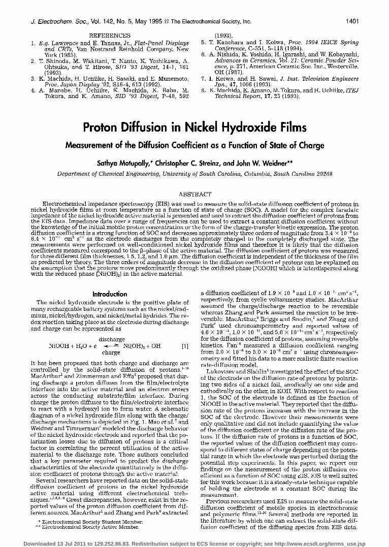
Results and Discussion Simulat ion resul t s . - -The effect of varying the diffusion
coefficient and the thickness of the film on the diffusion- controlled Nyquist plane behavior is simulated using Eq. 9 and illustrated in Fig. 3a and b, respectively. Several inves- tigators n-2~ have discussed the behavior of the modified Warburg impedance and reported that it is characterized by three distinct regions, viz. the semi-infinite diffusion, transition, and finite diffusion regions. The frequency ranges in which the three regions are observed is controlled by the values of the diffusion coefficient and the thickness of the film. At high frequencies when ~o >> D/l 2, the hyper- bolic cotangent term tends to unity, the modified Warburg impedance behaves like the conventional Warburg imped- ance, and a straight line region with a slope of 45 ~ is ob- served on a Nyquist plot. At lower frequencies, when
<< D/I ~ the phase angle tends to infinity and a vertical line region perpendicular to the real axis is seen on a Nyquist plot. In this region, the diffusion behavior is l im- ited by the finite length of the film and a capacitive effect is observed on the Nyquist plot due to charge saturation. *~
At intermediate frequencies when ~ - D/l ~, a transition from the semi-infinite diffusion region to the finite diffu- sion region is seen. The region between the semi-infinite diffusion region and the finite diffusion region is called the transition region36
Figure 3a shows Nyquist plot simulations for D = 1.0 x 10 _9 and 3.0 x 10 _9 cm 2 s 1 and l = 1.5 ~m and Fig. 3b contains simulations for D = 1.0 x 10 -9 and l = 1.0, 1.2, and 1.5 ~m. For illustration, ~ and the charge-transfer resist- ance in Eq. 9 were set equal to 5.0 s u2 and 22.0 ~, respec- tively, for all the simulations presented here. The charge- transfer resistance and ~r affect only the magnitude of the impedance and not the slope of the Nyquist plot in the frequency range where diffusion is the rate-l imiting pro- cess. We can see from Fig. 3a that both the Nyquist plots exhibit each of the three characteristic regions and that the onset of the transition region is observed earlier (at higher frequencies) as the value of the diffusion coefficient in- creases. From Fig. 3b, we can observe that the increase in the film thickness has the same effect as a decrease in the diffusion coefficient. Therefore, if the diffusion coefficient of protons decreases as a function of SOC, the onset of the transition region must be observed at progressively lower frequencies as the electrode is discharged. At any SOC, the onset of the transition region must be observed at higher frequencies as the thickness of the film is decreased. For example, for the 1.0 Fm film, the onset of the transition region must be observed at a frequency which is approxi- mately 2.25 times the corresponding frequency for the 1.5 ~m film.
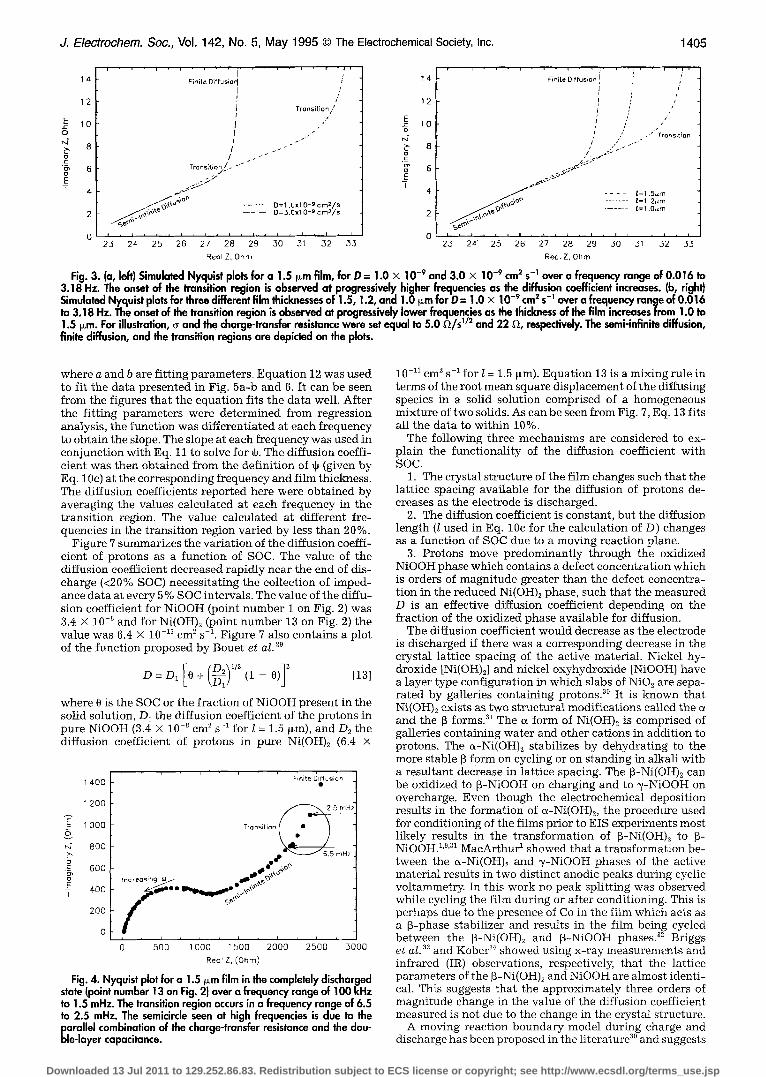
Experimental results.-- Figure 4 shows the Nyquist plot obtained for the 1.5 btm thick film, in the completely dis- charged state (point number 13 on Fig. 2), over a frequency range of I00 kHz to 1.5 mHz. At high frequencies the semi- circle is characteristic of the charge-transfer resistance acting in parallel with the double-layer capacitance. At intermediate frequencies (0.085-0.0075 Hz) a straight line with a slope of -45 ~ is seen, characteristic of the semi-in- finite diffusion. At still lower frequencies (<1.5 mHz), the finite length effects are observed, and there is a transition from the 45 ~ line toward a vertical line through the transi- tion region which lies in a frequency range of 6.5 to 2.5 mHz. In the finite diffusion region, it was only possible to get two data points owing to the need for extremely time-consuming low frequency measurements. The transi- tion region for a fully discharged film was observed in a frequency range which was approximately three orders of magnitude less than the corresponding range for the com- pletely charged film. Impedance measurements at all other states of charge were made only over a limited range of frequencies in which diffusion control was observed and thus the data presented at the other SOC (Fig. 5a-b, 6) do not contain the semicircle.
Figure 5a shows Nyquist plots at 80 and 60% SOC and Fig. 5b shows the Nyquist plots obtained for 50 and 30% SOC over the frequency range in which diffusion domi- nates. The frequency range over which impedance mea- surements were made for the 80 and 60% SOC was 0.3-11.9 and 0.15-5.65 Hz, respectively. For the 50 and 30% SOC, the corresponding frequency ranges are 0.05-5.65 and 0.03- 1.13 Hz, respectively. The frequency at which the onset of the transition region is observed is marked on the plots. It can be seen that the onset of the transition region shifts to lower frequencies at lower SOC indicating that the diffu- sion coefficient is steadily decreasing with decreasing SOC. Figure 6 shows Nyquist plots at 40% SOC for three differ- ent films 1.5, 1.2, and 1.0 b~m thick. The frequency range over which impedance measurements were made for all three thicknesses is the same (0.09-3.4 Hz). The frequencies at which the onset of the transition region was observed is also marked on the plot.
The diffusion coefficient at all SOC was determined at each frequency in the transition region (typically 3-5 points) by performing a ]east squares fit of the data to the exponential function
I m = a exp (b Re) [12]
Downloaded 13 Jul 2011 to 129.252.86.83. Redistribution subject to ECS license or copyright; see http://www.ecsdl.org/terms_use.jsp
J. Electrochem. Sac., Vol. 142, No. 5, M a y 1995 �9 The Electrochemical Society, Inc. 1405
14- Finite Oiffuslo~' / 14 Finite Diffusion !" : ' I j J : i I ' 12 I : '
I 2 I Trans t on ' I : '
E 10 I ~ 10 ,' " ~:) f o I .." Transition r4 / ..- ~ "
8 I .-" >, 8 / / -""
Tro ns;Uo~/( - . "" c. "6~ 6 - 6 .-z~"
/ O.-~os~ ~ ........ ~ 9 . ~ { ~ , ~ .. . . . . . /=1.2~.m ~ ' " ~ O=3,Oxl 0 -9 cm~/s 2
2 ~M D=I"OxlO-~ cm2/s ..... L=I .O/~m
0 23 24 25 28 29 30 ,31 52 ,35 23 24" 25 26 27 28 29 50 31 32 53 Reel Z, Ohm Rea. Z, Ohm
Fig. 3. (a, left) Simulated Nyquist plots for a 1.5 i~m film, for D = 1.0 x 10 -9 and 3.0 x 10- ' cm ~ s -~ over a frequency range of 0.016 to 3.18 Hz. The onset of the transition region is observed at progressively higher frequencies as the diffusion coefficient increases. (b, right) Simulated Nyquist plots for three different film thicknesses of 1.5, 1.2, and 1.0 l~m for D = 1.0 x 10 -~ cm ~ s-' over a frequency range of 0.016 to 3.18 Hz. The onset of the transition region is observed at progressively lower frequencies as the thickness of the film increases from 1.0 to 1.5 i~m. Far illustration, (, and the charge-transfer resistance were set equal to 5.0 ~l/s ~1~ and 22 Q, respectively. The semi-infinite diffusion, finite diffusion, and the transition regions are depicted on the plots.
where a and b are fitting parameters. Equation 12 was used to fit the data presented in Fig. 5a-b and 6. It can be seen from the figures that the equation fits the data well. After the fitting parameters were determined from regression analysis, the function was differentiated at each frequency to obtain the slope. The slope at each frequency was used in conjunction with Eq. 1 1 to solve for ~. The diffusion coeffi- cient was then obtained from the definition of ~ (given by Eq. 10c) at the corresponding frequency and film thickness. The diffusion coefficients reported here were obtained by averaging the values calculated at each frequency in the transition region. The value calculated at different fre- quencies in the transition region varied by less than 20%.
Figure 7 summarizes the variation of the diffusion coeffi- cient of protons as a function of SOC. The value of the diffusion coefficient decreased rapidly near the end of dis- charge (<20% SOC) necessitating the collection of imped- ance data at every 5 % SOC intervals. The value of the diffu- sion coefficient for NiOOH (point number 1 on Fig. 2) was 3.4 • i0 -~ and for Ni(OH)2 (point number 13 on Fig. 2) the value was 6.4 • i0 11 cm 2 s i. Figure 7 also contains a plot of the function proposed by Bouet et aL 2o
D=DI[O+(D2~ 1/2\~/ (i - 0 ) ] ~ [13]
where 0 is the SOC or the fraction of NiOOH present in the solid solution, D~ the diffusion coefficient of the protons in pure NiOOH (3.4 x 10 -~ cm 2 s -1 for l = 1.5 ~m), and D2 the diffusion coefficient of protons in pure Ni(OH)2 (6.4 x
1 400
1 200
"E 1 0 0 0 z- o
800
. co 600 ,
_E 400 I
200
. , r , , , , , , .
Finite D~fus~on
~ r n H ;
Tronsitian _ ~ ~
dp 6.5 mHz
~_~.. ,..,.._.... %,~ s,'~
i i i i i i i
0 500 1000 1500 2000 2500 3000 Real Z, (Ohm)
Fig. 4. Nyquist plot for a 1.5 I~m film in the completely discharged state (point number 13 on Fig. 2) over a frequency range of 100 kHz to 1.5 mHz. The transition region occurs in a frequency range of 6.5 to 2.5 mHz. The semicircle seen at high frequencies is due to the parallel combination of the charge-transfer resistance and the dou- ble-layer capacitance.
1 0 - l l c m 2 s - 1 for l = 1.5 ~m). Equation 13 is a mixing rule in terms of the root mean square displacement of the diffusing species in a solid solution comprised of a homogeneous mixture of two solids. As can be seen from Fig. 7, Eq. 13 fits all the data to within 10%.
The following three mechanisms are considered to ex- plain the functionality of the diffusion coefficient with SOC.
1. The crystal structure of the film changes such that the lattice spacing available for the diffusion of protons de- creases as the electrode is discharged.
2. The diffusion coefficient is constant, but the diffusion length (l used in Eq. 10c for the calculation of D) changes as a function of SOC due to a moving reaction plane.
3. Protons move predominantly through the oxidized NiOOH phase which contains a defect concentration which is orders of magnitude greater than the defect concentra- tion in the reduced Ni(OH)2 phase, such that the measured D is an effective diffusion coefficient depending on the fraction of the oxidized phase avaitable for diffusion.
The diffusion coefficient would decrease as the electrode is discharged if there was a corresponding decrease in the crystal lattice spacing of the active material. Nickel hy- droxide [Ni(OH)2] and nickel oxyhydroxide [NiOOH] have a layer type configuration in which slabs of NiO2 are sepa- rated by galleries containing protonsP ~ It is known that Ni(OH)2 exists as two structural modifications called the and the ~ forms? 1 The ~ form of Ni(OH)2 is comprised of galleries containing water and other cations in addition to protons. The ~-Ni(OH)2 stabilizes by dehydrating to the more stable [~ form on cycling or on standing in alkali with a resultant decrease in lattice spacing. The ~-Ni(OH)2 can be oxidized to ~-NiOOH on charging and to ~/-NiOOH on overcharge. Even though the electrochemical deposition results in the formation of a-Ni(OH)2, the procedure used for conditioning of the films prior to EIS experiments most likely results in the transformation of ~-Ni(OH)2 to ~- NiOOH. 1'9'31 MacArthur ~ showed that a transformation be- tween the ~-Ni(OH)2 and ~/-NiOOH phases of the active material results in two distinct anodic peaks during cyclic voltammetry. In this work no peak splitting was observed while cycling the film during or after conditioning. This is perhaps due to the presence of Co in the film which acts as a p-phase stabilizer and results in the film being cycled between the ~-Ni(OH)2 and ~-NiOOH phases? 2 Briggs et aL 33 and Kober 34 showed using x-ray measurements and infrared (IR) observations, respectively, that the lattice parameters of the ~-Ni(OH)2 and NiOOH are almost identi- cal. This suggests that the approximately three orders of magnitude change in the value of the diffusion coefficient measured is not due to the change in the crystal structure.
A moving reaction boundary model during charge and discharge has been proposed in the literature 3~ and suggests
Downloaded 13 Jul 2011 to 129.252.86.83. Redistribution subject to ECS license or copyright; see http://www.ecsdl.org/terms_use.jsp

1406 J. Electrochem. Sac., Vol. 142, No. 5, May 1995 �9 The Electrochemical Society, Inc.
1 2 , , , , , i , ,
11 0.15 Ftz
10
9
o N - 7
' ) 5
T 0 ~ I , I , ~ I ~ I ~ I i
30
20
24 25 26 27 28 2g 50 51 52
Hz
50z s0c 507. s0c
10
E
~4 b o E
0
E I
Real Z. Ohm
r , i
70
" 0.03 50
5O
4O
0"05 f
/ / < 0.17Hz
/ :
0 i I i I , I i I t I i
20 30 40 50 60 70 80 Real Z, Ohm
Fig. 5. (a, top) Nyquist plot for a 1.5 i~m film at 80 and 60% states of charge over a frequency range of 0.3-11.9 and 0.15-5.65 Hz, respectively. The frequencies at which the onset of the transition region for the 80 and 60% states of charge is observed is 1.3 and 0.65 Hz, respectively. (b, bottom} Nyqulst plot for a 1.5 ~m film at 50 and 30% states of charge over a frequency range of 0.05-5.6 and 0.03-1.1 Hz, respectively. The frequency at which the onset of the transition region for the 50 and 30% states of charge is seen is 0.45 and 0.17 Hz, respectively. The data is fit to Eq. 12. The onset of the transition region shifts to lower frequencies as the sac decreases indicating that the diffusion coefficient is decreasing as a function of sac.
40
.30
E x "
0
r-J b o 20
O
E
10
0 ~ I ~ I
26 28 30
�9 t=1.0p.m [= 1.2#m
�9 t=1.5/~m
52 54 56 58 40 42 44 46 48 50
Real Z, Ohm
that the diffusion length of the protons is changing as a function of SOC. The active material in the reduced form [Ni(OH)2] is pale green in color and is black in the oxidized form [NiOOH], and some researchers have observed the motion of a color boundary during the charge and dis- charge of the active material. 3~'36 Huggins e t al. ~o attribute this moving color boundary to the movement of the NiOOH/Ni(OH)2 interface. According to the authors, the charge/discharge reaction takes place at the NiOOH/ Ni(OH)2 boundary (i .e. , reaction plane) and this boundary
Fig. 6. Nyquist plots far three different thicknesses of 1.5, !.2, and 1.0 ~m at 40% sac. The onset of the transition region is seen at 0.27, 0.38, and 0.51 Hz, respectively. The data is fit to Eq. 12. The onset of the transiton region is observed at pregressively higher frequen- cies as the film thickness decreases.
moves from the film/electrolyte interface toward the con- ducting substrate/film interface during discharge and vice versa during charge. If the notion of a sharp moving reac- tion plane is true, the value of the diffusion length in the transition region is not equal to the thickness of the film but- is a function of the SOC given by
=/(1 - O) [14]
where B is the distance from the reaction plane to the film/ electrolyte interface. Therefore B will be equal to the thick- ness of the film at 0% SOC and equal to zero when the electrode is fully charged. It is possible to obtain the value of D/S 2 at all states of charge by dividing D2 (diffusion coefficient in the completely discharged state), by the square of the right side of Eq. 14.
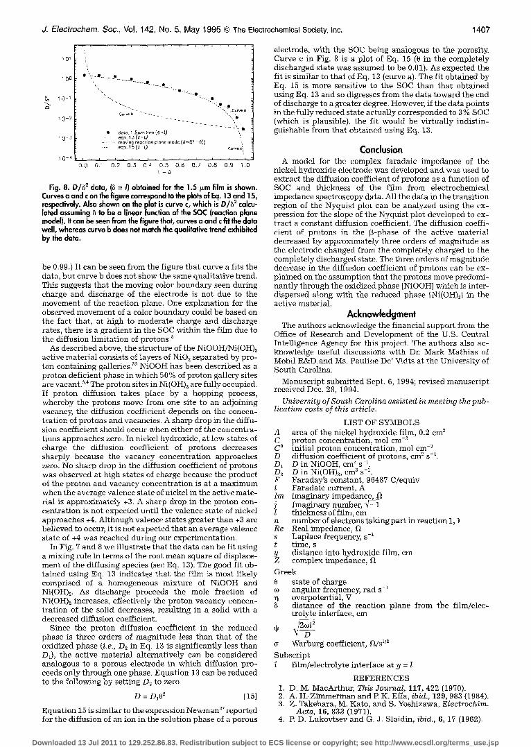
In Fig. 8, the D/B 2 data obtained for the 1.5 ~m film is plotted along with the corresponding fit (curve a) utilizing Eq. 13 (with t = 8). Also plotted on Fig. 8, is D/B 2 for a moving reaction plane where D = D2 and ~ = / (i - 0) (curve b). (Note: 0 in the completely charged state was assumed to
E o
._e ._o 1 0 -
o g 2
k5
2
1 0 11
, ' . i . , , , . , , , �9 , . , . , �9 , , ,
i ...... | ..... P.
"~.,.~ A@ 1 . 5 ~ . r n f i l m
�9 1 . 0 p . m f i l m ' ~ - - - e q u a t i o n 1 3 ,
i . ~ . i , i , i i i , i I i i , i J O
0 . 0 0 . 1 0 . 2 0 . . ~ 0 . 4 0 . 5 0 . 6 Q . 7 0 8 0 . 9 1 .
Fig. 7. Diffusion coefficient of protons in the nickel hydroxide film as a function of sac. The diffusion coefficient of protons decreases approximately three orders of magnitede as the electrode changes from the completely charged to the completely discharged state. Equation 13 is plol~cl along with the data.
Downloaded 13 Jul 2011 to 129.252.86.83. Redistribution subject to ECS license or copyright; see http://www.ecsdl.org/terms_use.jsp
J. Electrochem. Soc., Vol. 142, No. 5, May 1995 �9 The Electrochemical Society, Inc. 1407
I0 o $ - ' - - ~ " �9 �9 �9 . . . . . o .
,% 10-1 " . "--:o
~ " " ~ " - - ", " .Curvea Cu~e b " " -
t 0 _ 2 - - ~ - _ ",, ~
�9 do~,o. 1.51~,m film (6 = L) ~ 1 0 - 3 eqn. 15(6=l)
...... mo,~n~ reac t ion prone mode[(6=l(1 -{)) ) ',
. . . . . . eqn. 15 (~=/) Cucve c i
1 0 - 4 : ' ' ' ' . . . . . . i ' ' ' ' . ' : . . . . 0 O 0 0.1 0 2 0 .3 0 '~ 0 5 0 . 6 0 7 0 8 0 .9 1
1 - 6
Fig. 8. D/82 data, (8 = I) obtained for the 1.5 Fm film is shown. Curves a and c on the figure correspond to the plots of Eq. 13 and 15, respectively. Also shown on the plot is curve c, which is D/6 2 calcu- lated assuming ~ to be a linear function of the SOC (reaction plane model). It can be seen from the figure that, curves a and c fit the data well, whereas curve b does not match the qualitative trend exhibited by the data.
be 0.99.) It can be seen from the figure that curve a fits the data, but curve b does not show the same qualitative trend. This suggests that the moving color boundary seen during charge and discharge of the electrode is not due to the movement of the reaction plane. One explanation for the observed movement of a color boundary could be based on the fact that, at high to moderate charge and discharge rates, there is a gradient in the SOC within the film due to the diffusion limitation of protons#
As described above, the structure of the NiOOH/Ni(OH)2 active material consists of layers of NiO2 separated by pro- ton containing galleries# ~ NiOOH has been described as a proton deficient phase in which 50% of proton gallery sites are vacant. 3'4 The proton sites in Ni(OH)2 are fully occupied. If proton diffusion takes place by a hopping process, whereby the protons move from one site to an adjoining vacancy, the diffusion coefficient depends on the concen- tration of protons and vacancies. A sharp drop in the diffu- sion coefficient should occur when either of the concentra- tions approaches zero. In nickel hydroxide, at low states of charge the diffusion coefficient of protons decreases sharply because the vacancy concentration approaches zero. No sharp drop in the diffusion coefficient of protons was observed at high states of charge because the product of the proton and vacancy concentration is at a maximum when the average valence state of nickel in the active mate- rial is approximate}y +3. A sharp drop in the proton con- centration is not expected unti l the valence state of nickel approaches +4. Although valence states greater than +3 are believed to occur, it is not expected that an average valence state of +4 was reached during our experimentation.
In Fig. 7 and 8 we illustrate that the data can be fit using a mixing rule in terms of the root mean square of displace- ment of the diffusing species (see Eq. 13). The good fit ob- tained using Eq. 13 indicate.s that the film is most likely comprised of a homogeneous mixture of NiOOH and Ni(OH)~. As discharge proceeds the mole fraction of Ni(OH)2 increases, effectively the proton vacancy concen- tration of the solid decreases, resulting in a solid with a decreased diffusion coefficient.
Since the proton diffusion coefficient in the reduced phase is three orders of magnitude less than that of the oxidized phase (i.e., D~ in Eq. 13 is significantly less than D~), the active material alternatively can be considered analogous to a porous electrode in which diffusion pro- ceeds only through, one phase. Equation 13 can be reduced to the following by setting D2 to zero
D = D102 [15]
Equation 15 is similar to the expression Newman 37 reported for the diffusion of an ion in the solution phase of a porous
electrode, with the SOC being analogous to the porosity. Curve c in Fig. 8 is a plot of Eq. 15 (0 in the completely discharged state was assumed to be 0.01). As expected the fit is similar to that of Eq. 13 (curve a). The fit obtained by Eq. 15 is more sensitive to the SOC than that obtained using Eq. 13 and so digresses from the data toward the end of discharge to a greater degree. However, if the data points in the fully reduced state actually corresponded to 3 % SOC (which is plausible), the fit would be virtually indist in- guishable from that obtained using Eq. 13.
Conclusion A model for the complex faradaic impedance of the
nickel hydroxide electrode was developed and was used to extract the diffusion coefficient of protons as a function of SOC and thickness of the film from electrochemical impedance spectroscopy data. All the data in the transition region of the Nyquist plot can be analyzed using the ex- pression for the slope of the Nyquist plot developed to ex- tract a constant diffusion coefficient. The diffusion coeffi- cient of protons in the [~-phase of the active material decreased by approximately three orders of magnitude as the electrode changed from the completely charged to the completely discharged state. The three orders of magnitude decrease in the diffusion coefficient of protons can be ex- plained on the assumption that the protons move predomi- nant ly through the oxidized phase [NiOOH] which is inter- dispersed along with the reduced phase [Ni(OH)2] in the active material.
Acknowledgment The authors acknowledge the financial support from the
Office of Research and Development of the U.S. Central Intelligence Agency for this project. The authors also ac- knowledge useful discussions with Dr. Mark Mathias of Mobil R&D and Ms. s De' Vidts at the University of South Carolina.
Manuscript submitted Sept. 6, 1994; revised manuscript received Dec. 28, 1994.
University of South Carolina assisted in meeting the pub- lication costs of this article.
LIST OF SYMBOLS A area of the nickel hydroxide film, 0.2 cm 2 C proton concentration, mol cm -3 C O initial proton concentration, tool cm -3 D diffusion coefficient of protons, cm 2 s -1. D1 D in NiOOH, cm 2 s -1. D2 D in Ni(OH)2, cm ~ s-:. F Faraday's constant, 96487 C/equiv i Faradaic current, A Im imaginary i m p e d a n c ~ j Imaginary number, # - 1 l thickness of film, cm n number of electrons taking part in reaction 1, 1 Re Real impedance, s Laplace frequency, s -1 t time, s y distance into hydroxide film, cm Z complex impedance,
Greek O state of charge o~ angular frequency, r a d s -1
overpotential, V distance of the reaction plane from the film/elec- trolyte interface, cm
e Warburg coefficient, Ft/s 1/2
Subscript f film/electrolyte interface at y = l
REFERENCES 1. D. M. MacArthur, This Journal, 117, 422 (1970). 2. A. H..Zimmerman and P. K. Effa, ibid., 129, 983 (1984). 3. Z. Takehara, M. Kato, and S. Yoshizawa, EIectrochim.
Acta, 16, 833 (1971). 4. P. D. Lukovtsev and G. J. Slaidin, ibid., 6, 17 (1962).
Downloaded 13 Jul 2011 to 129.252.86.83. Redistribution subject to ECS license or copyright; see http://www.ecsdl.org/terms_use.jsp

1408 J. Electrochem. Soc., Vol. 142, No. 5, May t995 �9 The Electrochemical Society, Inc.
5. G. W. D. Briggs and P. R. Snodin, ibid., 27, 565 (1982). 6. C. Zhang and S. Park, This Journal, 134, 2966 (1987). 7. Z. Mao, R De Vidts, R.E. White, and J. Newman, ibid.,
141, 54 (1994). 8. J. W. Weidner and P. Timmerman, ibid., 141,346 (1994). 9. D. M. MacArthur, ibid., 117, 729 (1970).
10. D. Fan, Ph.D. Thesis, Texas A&M University, College Station, TX (1991).
11. C. Ho, I. D. Raistrick, and R. A. Huggins, This Journal, 127, 343 (1980).
12. R. D. Armstrong, B. Lindhom, and M. Sharp, J. Elec- troanal. Chem., 2@2, 69 (1986).
13. J. P. Randin and R. Viennet, This Journal, 129, 2349 (1982).
14. J. Farcy, R. Messina, and J. Perichon, ibid., 137, 1337 (1990).
15. R. Cabanel, G. Barral , J. P. Diard, B. Le Gorrec, and C. Montella, J. Appl. Electrochem., 23, 93, (1993).
16. R. D. Armstrong, J. Electroanal. Chem., 198, 177 (1986).
17. G. Lang and G. Inzelt, Electrochim. Acta, 36, 847, (1991).
18. I. Rubinstein, J. Risphon, and S , Gottesfeld, This Jour- nal, 133, 729, (1986).
19. T. B. Hunter, P. S. Tyler, W. H. Smyrl, and H. S. White, ibid., 134, 2198, (1987).
20. M. E Mathias and O. Haas, J. Phys. Chem., 96, 3174, (1992).
21. D. Fan and R. E. White, This Journal., 138, 2952 (1991). 22. B. A. Boukamp and G. A. Wiegers, Solid State Ionics,
9&lO, 1193, {1983). 23. R A. Antonenko, V. Z. Barusukov, N. G. Krapivnii , and
L. N. Sagoyan, Vopr. Khim. Khim. Teknol. (Kharkov),
25, 135 (1972). 24. M. J. Natan, D. Belanger, M. K. Carpenter, and M. S.
Wright@n, J. Phys. Chem., 91, 1834 (1987). 25. C. C. Streinz, A. P. Hartman, S. MotupaUy, and J. W.
Weidner, This Journal, 142, 1084 (1995). 26. B. A. Johnson, R. E. Ferro, G. M. Swain, and B. J.
Tatarchuk, J. Power Sources, 47, 251 (1994). 27. A.H. Zimmerman and P. K. Ella, Abst rac t 28, p. 43, The
Electrochemical Society Extended Abstracts , Vol. 85-2, Las Vegas, NV, Oct. 13-18, 1985.
28. B. E. Conway and P. L. Bourgalt, Trans. Faraday Soc., 58, 593, (1962).
29. J. Bouet, E Richard, and R Blanchard, in Proceedings of the Symposium on Nickel Hydroxide Electrodes, D. A. Corrigan and A. H. Zimmerman, Editors, PV 90-4, p. 260, The Electrochemical Society Pro- ceedings Series, Pennington, NJ (1990).
30. R. A. Huggins, M. Wohlfahrt-Mehrens, and L. Jor- inssen, Mat. Res. Soc. Symp. Proc., 293, 57 (1993).
31. H. Bode, K. Dehmelt, and J. Witte, Electrochim. Acta., 11, 1079 (1966).
32. O.G. Malandin, A. V. Vasev, P. N. Bityutskii , I. S. Sham- ina, and G. V. Suchkova, Elektrokhimiya, 14, 91 (1978).
33. G. W. D. Briggs, E. Jones, and W. F. K. Wynne-Jones, Trans. Faraday Soc., 51, 394 (1955).
34. E P Kober, This Journal, 112, 1064 (1965). 35. R. Barnard, C. F. Rande]l, and F. L. Tye, J. Appl. Elec-
trochem., 1O, 109, (1980). 36. G. W. D. Briggs and M. Fleischmann, Trans. Faraday
Soc., 67, 2397, (1971). 37. J. Newman, Electrochemical Systems, Prentice Hall
Inc., Englewood Cliffs, NJ (1973).
Downloaded 13 Jul 2011 to 129.252.86.83. Redistribution subject to ECS license or copyright; see http://www.ecsdl.org/terms_use.jsp