prototrak trl & lx2€¦ · 5.6 connective events 31 5.7 conrad 31 5.8 chamfer ... 10.10 fault...
TRANSCRIPT
TRAK® TRL &
ProtoTRAK LX2
Safety, Programming, Operating and Care Manual
Document: P/N 20099 Version: 052814
Southwestern Industries, Inc. 2615 Homestead Place Rancho Dominguez, CA 90220-5610 USA T | 310.608.4422 | F | 310. 764.2668
Service Department: 800.367.3165 e-mail: [email protected] | [email protected] | web: southwesternindustries.com
Copyright 2013, Southwestern Industries, Inc. All rights are reserved. No part of this
publication may be reproduced, stored in a retrieval system, or transmitted, in any form or by any means, mechanical, photocopying, recording or otherwise, without the prior written
permission of Southwestern Industries, Inc.
While every effort has been made to include all the information required for the purposes of this
guide, Southwestern Industries, Inc. assumes no responsibility for inaccuracies or omission and accepts no liability for damages resulting from the use of the information contained in this guide.
All brand names and products are trademarks or registered trademarks of their respective holders.
Southwestern Industries, Inc.
2615 Homestead Place
Rancho Dominguez, CA 90220-5610 Phn 310.608.4422 Fax 310.764.2668
Service Department Phn 800.367.3165 Fax 310.886.8029
| i
_________________________________________________________________ Southwestern Industries, Inc.
TRAK TRL & ProtoTRAK LX2 Programming, Operating & Care Manual
_______________________ TABLE OF CONTENTS
Section
____________ 1.0 Introduction 2
Section
____________ 2.0 Safety, Specifications & Lubrication
2.1 Safety Publications 5 2.2 Danger, Warning, Caution and Note Labels and Notices As Used In This Manual 5 2.3 Safety Precautions 8 2.4 Specifications 10 2.5 Lubrication 11
Section
____________ 3.0 Description 3.1 LX2 Keyboard 14 3.2 LX2 Soft Keys 14 3.3 LX2 CRT Screen 15 3.4 LX2 Pendant Back Panel 15 3.5 TRL Switch Box 15 3.6 LX2 Computer Cabinet 15 3.7 The TRL Lathe 15
ii |
Section
____________ 4.0 TRAK TRL Machine Operation 4.1 Switching the TRAK TRL On/Off 21 4.2 Switching the ProtoTRAK LX2 On/Off 21 4.3 Spindle Forward/Off/Reverse 22 4.4 Changing Spindle Speeds 22 4.5 Using the Electronic Handwheels 24 4.6 Using the Jog Stick 24 4.7 Emergency Stop 24 4.8 Locking the Carriage 25 4.9 Tool Pedestal 25 4.10 Tail Stock 25 4.11 Coolant System 25
Section
____________ 5.0 Definitions, Terms & Concepts 5.1 ProtoTRAK LX2 Axis Conventions 28 5.2 Absolute & Incremental Reference 28 5.3 Referenced and Non-Referenced Data 29 5.4 Tool Tip Radius Compensation 29 5.5 Tool Offset 30 5.6 Connective Events 31 5.7 Conrad 31 5.8 Chamfer 32 5.9 Absolute, Tool, and Program References 33
| iii
Section
____________ 6.0 DRO Mode 6.1 Enter DRO Mode 35 6.2 Clear Entry 35 6.3 Inch to MM or MM to Inch 36 6.4 Reset One Axis 36 6.5 Preset 36 6.6 Reset Absolute Reference 36 6.7 Preset Absolute Reference 36 6.8 Recall Absolute Position of All Axes 36 6.9 Recall Absolute Position of One Axis 37 6.10 Change from Fine to Coarse Handwheel Resolution & Feed 37 6.11 Tool Number 37 6.12 Power Feed 37 6.13 Manual Go To 38 6.14 Return to Home 38 6.15 Do One Events 39 6.16 Tool Tip Radius Compensation in DRO Mode 41
Section
____________ 7.0 Program Mode 7.1 Enter Program Mode & Assign a Part Number 44 7.2 Incremental Reference Position 45 7.3 Programming Strategy and Procedures 45 7.4 Position Events 46 7.5 Drill Events 47 7.6 Bore Events 48 7.7 Turn Events 49 7.8 Arc Events 51 7.9 Cycle Events 52 7.10 Thread Event 55 7.11 Repeat Events 57 7.12 Aborting a Partially Programmed Event 58 7.13 Editing Data While Programming an Event 58 7.14 Finish Cuts 59 7.15 Sample Program 59
iv |
Section
____________ 8.0 Edit Mode 8.1 Enter Edit Mode 67 8.2 Recall and Data Correction 69 8.3 Adding an Event 69 8.4 Deleting an Event 69 8.5 Erasing a Program 69
Section
____________ 9.0 Set Up Mode 9.1 Enter Set Up Mode 72 9.2 Tool Set Up 72 9.3 A Practical Technique for Accurate Tool Setting 75 9.4 Tool Set Up When Adding or Changing Tools 75 9.5 Setting Home Position 76 9.6 Draw Part Graphics 76 9.7 Tool Path Graphics 77 9.8 Saving Tool Data 77 9.9 Service Codes 78
Section
____________ 10.0 Program Run Mode 10.1 Enter Run Mode 81 10.2 Starting to Run 81 10.3 Program Run 82 10.4 Program Run Messages 83 10.5 TRAKING 84 10.6 Stop 84 10.7 Feedrate Override 84 10.8 Threading Exceptions 85 10.9 Data Errors 85 10.10 Fault Messages 86
| v
Section
____________ 11.0 Math Help Mode 11.1 Procedure 88 11.2 Calculator-Math and Trig Procedures 90 11.3 Math Help Types 91
Section
____________ 12.0 Program In/Out Mode 12.1 Cautions About Storing & Retrieving Programs 95 12.2 Program Formats and Labeling 96 12.3 Enter Program In/Out Mode 96 12.4 Storing & Retrieving Programs from the ProtoTRAK LX2 Built-In Floppy Disk Drive 97 12.5 Backing Up Your LX2 Programs 98 12.6 Storing and Retrieving Programs through the RS232 Port - Including CAD/CAM Generated Programs

_________________________________________________________________ Southwestern Industries, Inc.
TRAK TRL & ProtoTRAK LX2 Programming, Operating & Care Manual
SECTION
____________ 1.0 _____________________________
Introduction
Introduction Section I.0 | 2
1.0 INTRODUCTION Congratulations! Your TRAK TRL is a unique, one-of-a-kind, machine tool which combines the simplicity of manual machining with the contouring capability of CNC turning centers. The TRAK TRL has been designed to maximize the interplay between manual and CNC machining. It acts like an advanced digital readout in manual machine operation. It acts like a turning center when programmed to do complex contouring jobs. And it acts with the best qualities of each when you manually feed programmed contours with the powerful TRAKing feature. Section 2 of this manual describes the necessary SAFETY PRECAUTIONS which must be learned and followed by each operator. Section 3 of this manual provides a brief description of the TRAK TRL. Section 4 of this manual describes the operation of the lathe. Section 5 defines some terms and concepts useful in learning to program and operate the ProtoTRAK LX2. The ProtoTRAK LX2 is organized into seven Modes of operation which are described in the following sections. Section 6 DRO: Digital Readout, and powerfeed, and Do One Programs Section 7 PROGRAM: All input in simple machinist language. Section 8 EDIT: Program review and edit. Section 9 SET UP: Tool information and part graphics. Section 10 RUN: Machining the part. Section 11 MATH HELP: Sophisticated routines to automatically calculate points of intersection, tangency, etc. Section 12 PROGRAM IN/OUT: CAD/CAM interface, and program storage and retrieval.
_________________________________________________________________ Southwestern Industries, Inc.
TRAK TRL & ProtoTRAK LX2 Programming, Operating & Care Manual
SECTION
____________ 2.0 _____________________________ Safety, Specifications & Lubrication

4 | Section 2.0 Safety, Specifications & Lubrication
2.0 SAFETY SPECIFICATIONS & LUBRICATION The safe operation of the TRAK TRL depends on its proper use and the precautions taken by each operator. Read and study this TRAK TRL & ProtoTRAK LX2 Programming, Operating, and Care Manual. Be certain that every operator understands the operation and safety requirements of this machine before its use. Always wear safety glasses and safety shoes. Always stop the spindle and check to ensure the CNC control is in the stop mode before changing or adjusting the tool or workpiece. Never wear gloves, rings, watches, long sleeves, neckties, jewelry, or other loose items when operating, or around the machine. Use adequate point of operation safeguarding. It is the responsibility of the employer to provide and ensure point of operation safeguarding per ANSI B11.6-1984.
2.1 Safety Publications Refer to and study the following publications for assistance in enhancing the safe use of this machine: Safety Requirements For The Construction, Care And Use of Lathes (ANSI B11.6-1984). Available from the American National Standards Institute, 11 West 42nd Street, New York, NY 10036. Concepts And Techniques Of Machine Safeguarding (OSHA Publication Number 3067). Available from The Publication Office - O.S.H.A., U.S. Department of Labor, 200 Constitution Avenue, NW, Washington, DC 20210. All other regulations specific to the State in which the machine is installed.
2.2 Danger, Warning, Caution, and Note Labels and Notices As Used In This Manual DANGER - Immediate hazards which will result in severe personal injury or death. Danger labels on the machine are red in color. WARNING - Hazards or unsafe practices which could result in severe personal injury and/or damage to the equipment. Warning labels on the

Safety, Specifications & Lubrication Section 2.0 | 5
machine are gold in color. CAUTION - Hazards or unsafe practices which could result in minor personal injury or equipment/product damage. Caution labels on the machine are gold in color. NOTE - Call attention to specific issues requiring special attention or understanding.
115 Volts 230 Volts 440 Volts
i00187
i00188
Safety & Information Labels Used On The TRAK TRL Lathe
It is forbidden by OSHA regulations and by law to deface, destroy or remove any of these labels

Safety, Specifications & Lubrication Section 2.0 | 7
i00426
Safety & Information Labels Used On The TRAK TRL Lathe
It is forbidden by OSHA regulations and by law to deface, destroy or remove any of these labels

8 | Section 2.0 Safety, Specifications & Lubrication
2.3 Safety Precautions
WARNING! Use only chucks which are rated to the maximum RPM of the lathe.
1. Do not operate this machine before the TRAK TRL & ProtoTRAK LX2 Programming, Operating and Care Manual have been studied and understood. 2. Do not run this machine without knowing the function of every control key, button, knob, or handle. Ask your supervisor or a qualified instructor for help when needed. 3. Protect your eyes. Wear approved safety glasses (with side shields) at all times. 4. Don't get caught in moving parts. Before operating this machine, remove all jewelry, including watches and rings, neckties, and any loose-fitting clothing. 5. Keep your hair away from moving parts. Wear adequate safety head gear. 6. Protect your feet. Wear safety shoes with oil-resistant, anti-skid soles, and steel toes. 7. Take off gloves before you start the machine. Gloves are easily caught in moving parts. 8. Remove all tools (wrenches, chuck keys, etc.) from the machine before you start. Loose items can become dangerous flying projectiles. 9. Never operate any machine tool after consuming alcoholic beverages, or taking strong medications, or while using non-prescription drugs. 10. Protect your hands. Stop the machine spindle and ensure that the CNC control is in the STOP mode: Before changing tools Before changing parts Before you clear away the chips, oil or coolant. Always use a chip scraper or brush Before you make an adjustment to the part, chuck, coolant nozzle or take measurements Before you open safeguards (protective shields, etc.). Never reach for the part, tool, or fixture around a safeguard. 11. Protect your eyes and the machine as well. Don't use a compressed air hose to remove the chips or clean the machine (oil, coolant, etc.).

Safety, Specifications & Lubrication Section 2.0 | 9
12. Stop and disconnect the power to the machine before you change belts, pulley, gears, etc. 13. Keep work area well lighted. Ask for additional light if needed. 14. Do not lean on the machine while it is running. 15. Prevent slippage. Keep the work area dry and clean. Remove the chips, oil, coolant and obstacles of any kind around the machine. 16. Avoid getting pinched in places where the spindle, carriage, or cross- slide create "pinch points" while in motion. 17. Securely clamp and properly locate the workpiece in the chuck or in the fixture. Use proper tool holding equipment. 18. Use correct cutting parameters (speed, feed, and depth of cut) in order to prevent tool breakage. 19. Use proper cutting tools for the job. 20. Prevent damage to the workpiece or the cutting tool. Never start the machine (including the rotation of the spindle) if the tool is in contact with the part. 21. Don't use dull or damaged cutting tools. They break easily and may become airborne. Inspect the sharpness of the edges, and the integrity of cutting tools and their holders. 22. Large overhangs on cutting tools when not required result in accidents and damaged parts. 23. Prevent fires. When machining certain materials (magnesium, etc.) the chips and dust are highly flammable. Obtain special instruction from your supervisor before machining these materials. 24. Prevent fires. Keep flammable materials and fluids away from the machine and hot, flying chips. 25. Changing the speed of rotation of the spindle must be done while the rotation is off. Never change gears when the spindle is rotating. 26. Do not rotate the spindle by hand unless the Red Emergency Stop button is pressed.
2.4 Specifications
10 | Section 2.0 Safety, Specifications & Lubrication
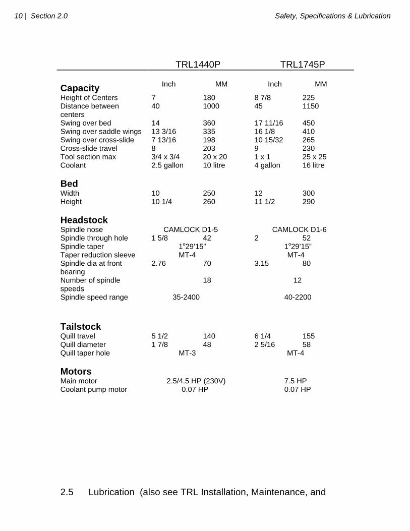
TRL1440P TRL1745P Capacity
Inch
MM
Inch
MM
Height of Centers 7 180 8 7/8 225 Distance between centers
40 1000 45 1150
Swing over bed 14 360 17 11/16 450 Swing over saddle wings 13 3/16 335 16 1/8 410 Swing over cross-slide 7 13/16 198 10 15/32 265 Cross-slide travel 8 203 9 230 Tool section max 3/4 x 3/4 20 x 20 1 x 1 25 x 25 Coolant 2.5 gallon 10 litre 4 gallon 16 litre
Bed
Width 10 250 12 300 Height 10 1/4 260 11 1/2 290
Headstock
Spindle nose CAMLOCK D1-5 CAMLOCK D1-6 Spindle through hole 1 5/8 42 2 52 Spindle taper 1o29’15” 1o29’15” Taper reduction sleeve MT-4 MT-4 Spindle dia at front bearing
2.76 70 3.15 80
Number of spindle speeds
18 12
Spindle speed range 35-2400 40-2200
Tailstock
Quill travel 5 1/2 140 6 1/4 155 Quill diameter 1 7/8 48 2 5/16 58 Quill taper hole MT-3 MT-4
Motors
Main motor 2.5/4.5 HP (230V) 7.5 HP Coolant pump motor 0.07 HP 0.07 HP
2.5 Lubrication (also see TRL Installation, Maintenance, and
Safety, Specifications & Lubrication Section 2.0 | 11
Service Manual) 2.5.1 Headstock Check the oil in the sight level when the machine has not run for several minutes. If low, fill to the sight level with Mobile DTE 24 or equivalent. DO NOT OVERFILL. Depending on operating conditions, usually about once a year, the headstock should be drained and thoroughly flushed out before adding new oil. Use a light blending oil with a small percentage of kerosene as a flushing agent. Run the machine several minutes without load with the Flushing oil. Drain it and replace with Mobile DTE 24 or equivalent to the sight Level. 2.5.2 Carriage, Cross-Slide, and Ballscrews The carriage, cross-slide, and ball screws are lubricated with an automatic oiler located on the back of the tail stock pedestal. The oiler provides one shot when the main power is turned on, and another periodically while the power remains on. See TRL Installation, Maintenance, and Service Manual to adjust. Check the oil level daily and refill with a high grade S.A.E. 30 oil. 2.5.3 Tail Stock Weekly oil the tail stock through its oilers with a high grade S.A.E. 30 oil.
_________________________________________________________________ Southwestern Industries, Inc.
TRAK TRL & ProtoTRAK LX2 Programming, Operating & Care Manual
SECTION
____________ 3.0 _____________________________ Description
13 | Section 3.0 Description
3.0 DESCRIPTION
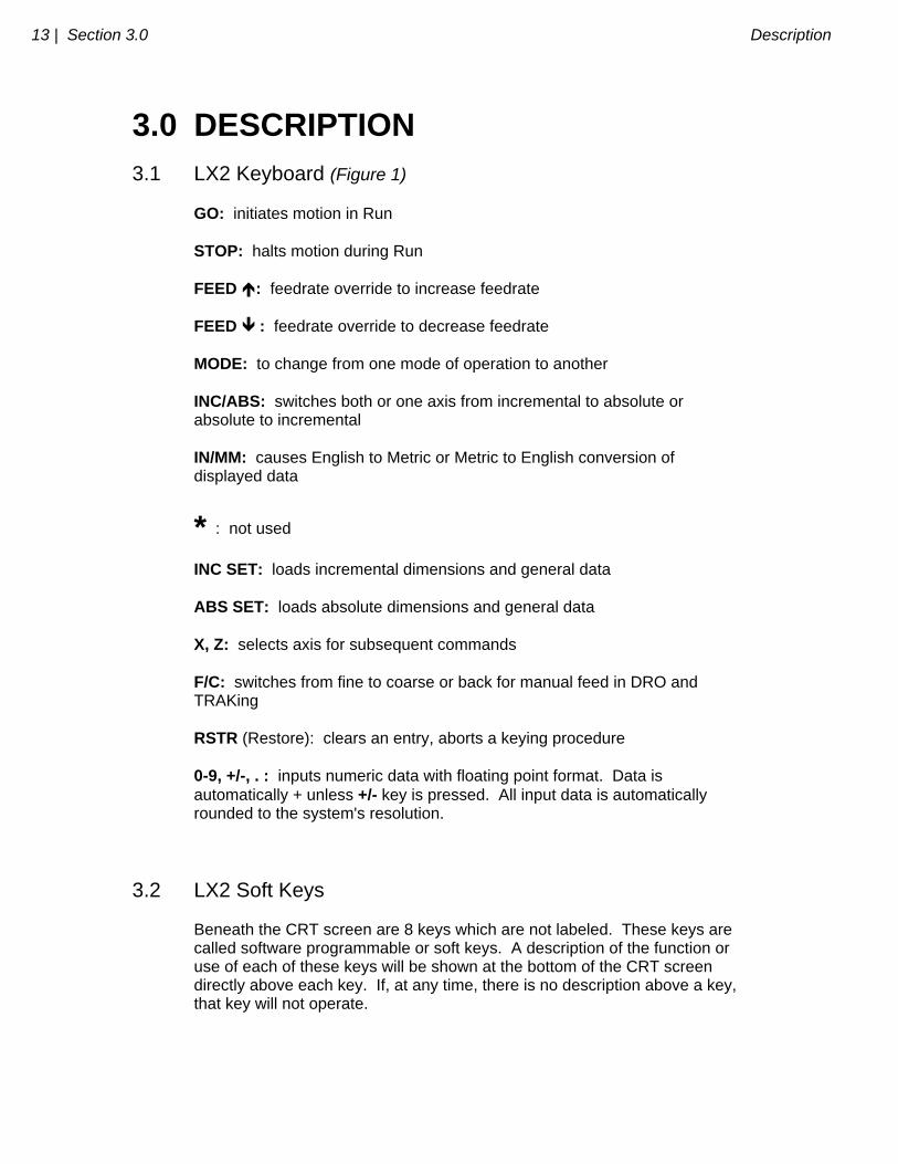
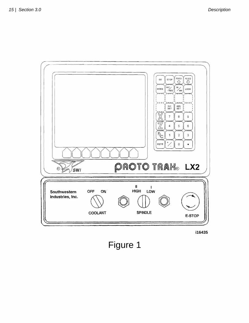
3.1 LX2 Keyboard (Figure 1) GO: initiates motion in Run STOP: halts motion during Run FEED : feedrate override to increase feedrate FEED : feedrate override to decrease feedrate MODE: to change from one mode of operation to another INC/ABS: switches both or one axis from incremental to absolute or absolute to incremental IN/MM: causes English to Metric or Metric to English conversion of displayed data
* : not used INC SET: loads incremental dimensions and general data ABS SET: loads absolute dimensions and general data X, Z: selects axis for subsequent commands F/C: switches from fine to coarse or back for manual feed in DRO and TRAKing RSTR (Restore): clears an entry, aborts a keying procedure 0-9, +/-, . : inputs numeric data with floating point format. Data is automatically + unless +/- key is pressed. All input data is automatically rounded to the system's resolution.
3.2 LX2 Soft Keys Beneath the CRT screen are 8 keys which are not labeled. These keys are called software programmable or soft keys. A description of the function or use of each of these keys will be shown at the bottom of the CRT screen directly above each key. If, at any time, there is no description above a key, that key will not operate.
Description Section 3.0 | 14
3.3 LX2 CRT Screen (Figure 1) The information displayed on the CRT screen is nearly always divided into 4 sections or areas. The top line, or status line, shows the system's current status. This includes the mode, inch or mm measurement, part numbers, servo on or off status as applicable, and fine/coarse handwheel resolution. Beneath the status line, and filling most of the screen, is the information area. Position data, program data, graphics, etc. are shown here. Beneath the information area is a single "conversation" line. All instructions, prompts, messages, etc. that the control needs to communicate to you are shown on this line. At the bottom of the CRT are boxes describing the current function or use of each soft key located under the box.
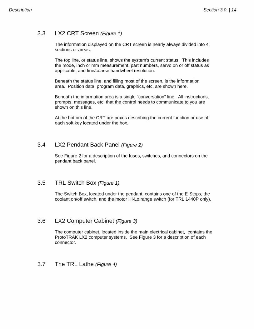
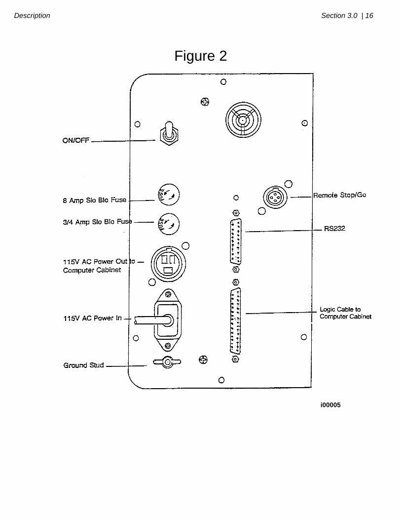
3.4 LX2 Pendant Back Panel (Figure 2) See Figure 2 for a description of the fuses, switches, and connectors on the pendant back panel.
3.5 TRL Switch Box (Figure 1) The Switch Box, located under the pendant, contains one of the E-Stops, the coolant on/off switch, and the motor Hi-Lo range switch (for TRL 1440P only).
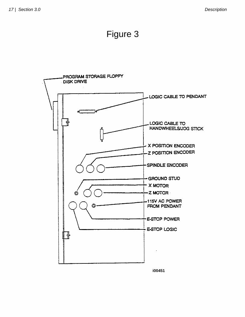
3.6 LX2 Computer Cabinet (Figure 3) The computer cabinet, located inside the main electrical cabinet, contains the ProtoTRAK LX2 computer systems. See Figure 3 for a description of each connector.
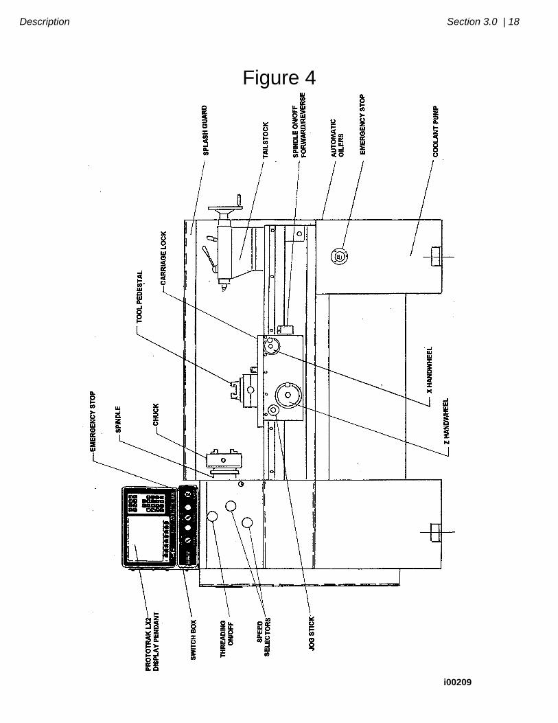
3.7 The TRL Lathe (Figure 4)
15 | Section 3.0 Description
i16435
Figure 1
Description Section 3.0 | 16
Figure 2
i00005
17 | Section 3.0 Description
Figure 3
i00451
Description Section 3.0 | 18
Figure 4
i00209
_________________________________________________________________ Southwestern Industries, Inc.
TRAK TRL & ProtoTRAK LX2 Programming, Operating & Care Manual
SECTION
____________ 4.0 _____________________________ TRAK TRL Machine Operation
20 | Section 4.0 TRAK TRL Machine Operation
4.0 TRAK TRL Machine Operation
4.1 Switching the TRAK TRL On/Off Power to the TRAK TRL is turned on through the main on/off switch located on the back of the main electrical cabinet.
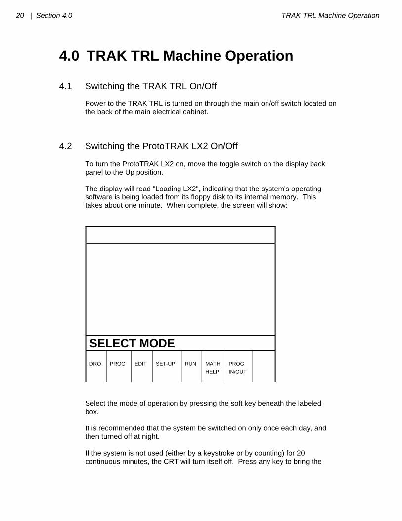
4.2 Switching the ProtoTRAK LX2 On/Off To turn the ProtoTRAK LX2 on, move the toggle switch on the display back panel to the Up position. The display will read "Loading LX2", indicating that the system's operating software is being loaded from its floppy disk to its internal memory. This takes about one minute. When complete, the screen will show:
SELECT MODE
DRO
PROG
EDIT
SET-UP
RUN
MATH
HELP
PROG
IN/OUT
Select the mode of operation by pressing the soft key beneath the labeled box. It is recommended that the system be switched on only once each day, and then turned off at night. If the system is not used (either by a keystroke or by counting) for 20 continuous minutes, the CRT will turn itself off. Press any key to bring the
TRAK TRL Machine Operation Section 4.0 | 21
screen back to its previous display. The key you press will be ignored except to turn the screen on. Note: When you turn the ProtoTRAK LX2 off, always wait a few seconds before turning it back on.
4.3 Spindle Forward/Off/Reverse (Figure 4) The Spindle Forward/Off/Reverse switch is located on the right side of the apron. Turn it to the left to 1 to activate the spindle in the forward (spindle rotates counterclockwise) direction. Turn it to the right to 2 to activate the spindle in the reverse (spindle rotates clockwise) direction. Off is the center.
4.4 Changing Spindle Speeds (Figure 4)
WARNING
DO NOT SHIFT HEADSTOCK GEARS WHILE THE SPINDLE OR
MOTOR IS RUNNING.
The spindle speed selection is made using the two shift levers located on the front of the headstock, and the I-II, 2-speed motor speed selector located in the switch box under the ProtoTRAK LX2 pendant (for TRL 1440P only).
22 | Section 4.0 TRAK TRL Machine Operation
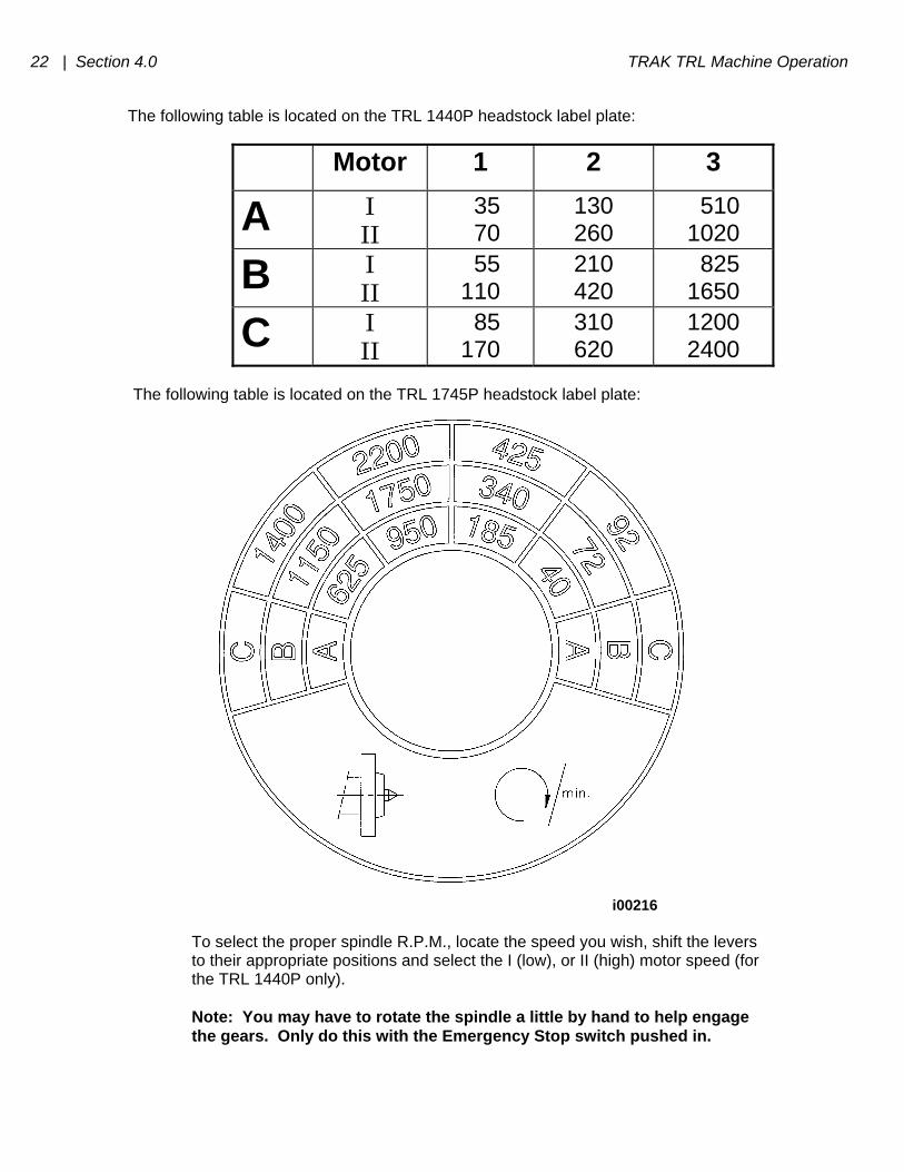
The following table is located on the TRL 1440P headstock label plate:
Motor 1 2 3
A I II
35 70
130 260
510 1020
B I II
55 110
210 420
825 1650
C I II
85 170
310 620
1200 2400
The following table is located on the TRL 1745P headstock label plate:
i00216 To select the proper spindle R.P.M., locate the speed you wish, shift the levers to their appropriate positions and select the I (low), or II (high) motor speed (for the TRL 1440P only). Note: You may have to rotate the spindle a little by hand to help engage the gears. Only do this with the Emergency Stop switch pushed in.
TRAK TRL Machine Operation Section 4.0 | 23
4.5 Using the Electronic Handwheels The X (cross-slide), and Z (carriage) handwheels are located on the apron. They are electronic, that is they are not mechanically connected to the machine, but rather create electronic signals to command the servo motors to drive the ball screws which, in turn, drive the carriage and cross-slide. The handwheels will not work unless the ProtoTRAK LX2 is turned on, and in the DRO mode, or in the Set Up mode, or in the TRAKing feature in the Run mode. Counterclockwise motion on the Z handwheel moves the carriage left 0.40" per revolution in .002" increments in coarse feed, or .10" per revolution in .0005" increments in fine feed. See Section 6.10 to switch from coarse to fine and back. Clockwise motion on the X handwheel moves the cross-slide away from you .10" per revolution in .0005" increments (on diameter) in coarse feed, or .02" per revolution in .0001" increments in fine feed. See Section 6.10 to switch from coarse to fine and back.
4.6 Using the Jog Stick The jog stick is located on the carriage apron directly above the Z electronic handwheel. The jog stick will operate only if the ProtoTRAK LX2 is turned on, and in the DRO mode or Set-Up mode, or in the TRAKing feature in the Run mode. Move the stick left or right to move the carriage left or right at 150 inches per minute. Move the stick up or down to move the cross-slide in or out at 100 inches per minute of diameter, or 50 inches per minute of actual cross-slide speed.
4.7 Emergency Stop There are two red Emergency Stop (E-STOP) mushroom buttons. One is located in the switch box beneath the ProtoTRAK LX2 pendant. The other is located on the tail stock pedestal. Press either to shut off power to the spindle motor, and carriage and cross-slide drive motors. Rotate the switch to turn it off only when the emergency condition has been rectified.
4.8 Locking the Carriage
24 | Section 4.0 TRAK TRL Machine Operation
The carriage position may be locked by tightening the square head bolt on the top right side of the carriage. This lock should rarely be required because the carriage position is held by the ball screw.
WARNING
BE CERTAIN THAT THE LOCK IS OFF BEFORE USING THE Z HANDWHEEL
OR JOG STICK, OR RUNNING A CNC PROGRAM..
4.9 Tool Pedestal The tool pedestal is held to the top of the cross-slide with four M 10 T-nuts. The pedestal may be rotated by loosening the T-nuts. Be certain to uniformly tighten the four nuts. A T-slot is machined on top of the pedestal which will accommodate most common tool posts.
4.10 Tail Stock The tail stock may be positioned along its V-way by releasing the lock with the lock handle. The quill may be locked with the quill lock at any position along its travel. The tail stock may be centered with the spindle through the set screw on the tail stock base.
4.11 Coolant System The coolant piping system may be mounted to the rear of the saddle with two screws. A 1/2 inch diameter hose connects the piping to the pump and reservoir located in the right pedestal base (see Figure 4). Access is through the right side. The reservoir holds 2 1/2 gallons of coolant and may be filled through the access, or by pouring the coolant into the chip pan. The coolant pump (and therefore the flow) may be switched on and off at the switch box located beneath the ProtoTRAK LX2 pendant. A nozzle on the piping allows you to regulate the flow.
_________________________________________________________________ Southwestern Industries, Inc.
TRAK TRL & ProtoTRAK LX2 Programming, Operating & Care Manual
SECTION
____________ 5.0 _____________________________ Definitions, Terms & Concepts
Definitions, Terms & Concepts Section 5.0 | 26
5.0 DEFINITIONS, TERMS & CONCEPTS
5.1 ProtoTRAK LX2 Axis Conventions Z Axis: positive Z axis motion is defined as the carriage moving to the right when facing the lathe. Measurement away from the chuck is positive on the workpiece. X Axis: positive X axis motion is defined as the cross-slide moving toward you. Measurement away from the part centerline and toward you is positive on the workpiece. All X motion is displayed as diameter (not radius) dimensions.
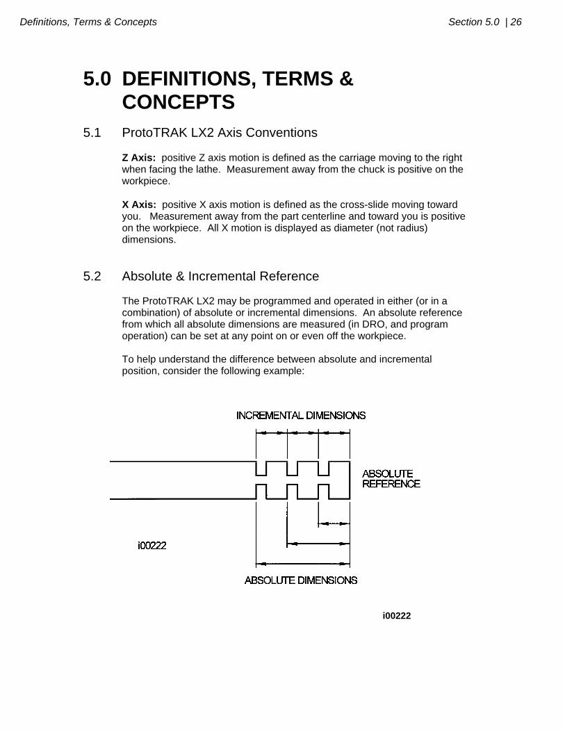
5.2 Absolute & Incremental Reference The ProtoTRAK LX2 may be programmed and operated in either (or in a combination) of absolute or incremental dimensions. An absolute reference from which all absolute dimensions are measured (in DRO, and program operation) can be set at any point on or even off the workpiece. To help understand the difference between absolute and incremental position, consider the following example:
i00222
27 | Section 5.0 Definitions, Terms & Concepts
5.3 Referenced and Non-Referenced Data Data is always loaded into the ProtoTRAK LX2 by using the INC SET or ABS SET key. X, Z positions are referenced data. In entering any X, or Z position data, you must note whether it is an incremental or absolute dimension and enter it accordingly. All other information (non-referenced data), such as tool offset, feedrate, etc. is not a position and may, therefore, be loaded with either the INC SET or ABS SET key. This manual uses the term SET when either INC SET or ABS SET may be used interchangeably.
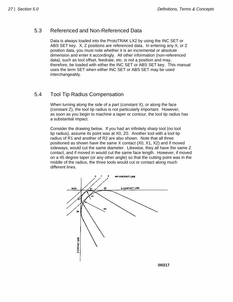
5.4 Tool Tip Radius Compensation When turning along the side of a part (constant X), or along the face (constant Z), the tool tip radius is not particularly important. However, as soon as you begin to machine a taper or contour, the tool tip radius has a substantial impact. Consider the drawing below. If you had an infinitely sharp tool (no tool tip radius), assume its point was at X0, Z0. Another tool with a tool tip radius of R1 and another of R2 are also shown. Note that all three positioned as shown have the same X contact (X0, X1, X2) and if moved sideways, would cut the same diameter. Likewise, they all have the same Z contact, and if moved in would cut the same face length. However, if moved on a 45 degree taper (or any other angle) so that the cutting point was in the middle of the radius, the three tools would cut or contact along much different lines.
i00217
Definitions, Terms & Concepts Section 5.0 | 28
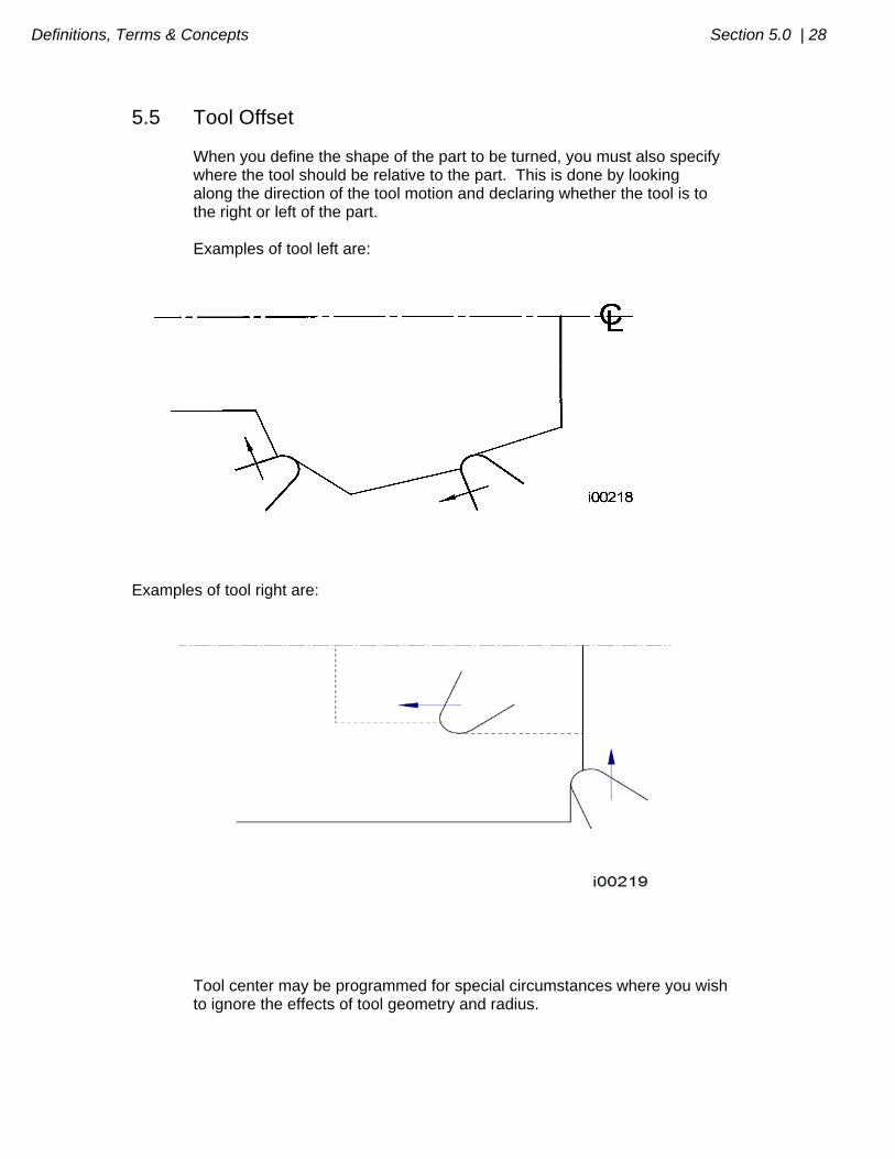
5.5 Tool Offset When you define the shape of the part to be turned, you must also specify where the tool should be relative to the part. This is done by looking along the direction of the tool motion and declaring whether the tool is to the right or left of the part. Examples of tool left are:
Examples of tool right are:
Tool center may be programmed for special circumstances where you wish to ignore the effects of tool geometry and radius.
29 | Section 5.0 Definitions, Terms & Concepts
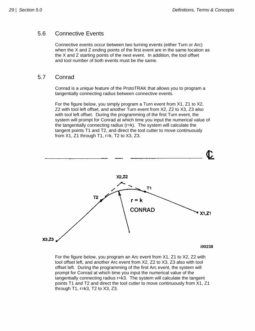
5.6 Connective Events Connective events occur between two turning events (either Turn or Arc) when the X and Z ending points of the first event are in the same location as the X and Z starting points of the next event. In addition, the tool offset and tool number of both events must be the same.
5.7 Conrad Conrad is a unique feature of the ProtoTRAK that allows you to program a tangentially connecting radius between connective events. For the figure below, you simply program a Turn event from X1, Z1 to X2, Z2 with tool left offset, and another Turn event from X2, Z2 to X3, Z3 also with tool left offset. During the programming of the first Turn event, the system will prompt for Conrad at which time you input the numerical value of the tangentially connecting radius (r=k). The system will calculate the tangent points T1 and T2, and direct the tool cutter to move continuously from X1, Z1 through T1, r=k, T2 to X3, Z3.
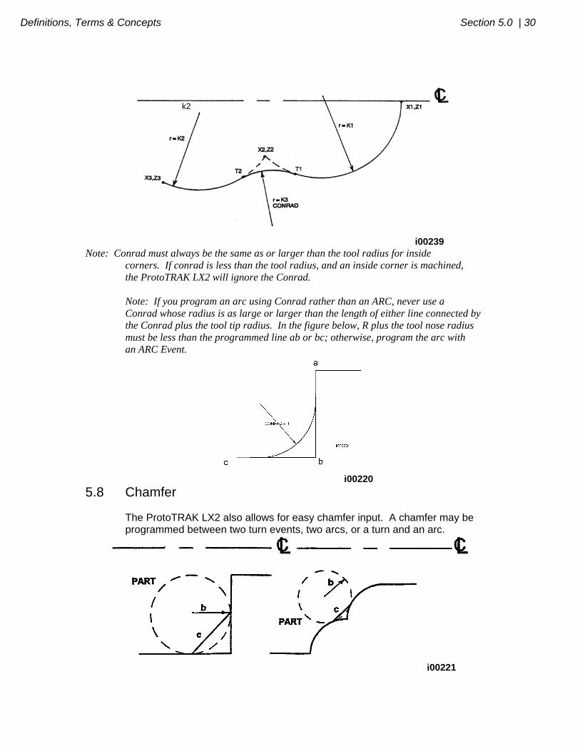
i00238 For the figure below, you program an Arc event from X1, Z1 to X2, Z2 with tool offset left, and another Arc event from X2, Z2 to X3, Z3 also with tool offset left. During the programming of the first Arc event, the system will prompt for Conrad at which time you input the numerical value of the tangentially connecting radius r=k3. The system will calculate the tangent points T1 and T2 and direct the tool cutter to move continuously from X1, Z1 through T1, r=k3, T2 to X3, Z3.
Definitions, Terms & Concepts Section 5.0 | 30
i00239
Note: Conrad must always be the same as or larger than the tool radius for inside corners. If conrad is less than the tool radius, and an inside corner is machined, the ProtoTRAK LX2 will ignore the Conrad. Note: If you program an arc using Conrad rather than an ARC, never use a Conrad whose radius is as large or larger than the length of either line connected by the Conrad plus the tool tip radius. In the figure below, R plus the tool nose radius must be less than the programmed line ab or bc; otherwise, program the arc with an ARC Event.
i00220
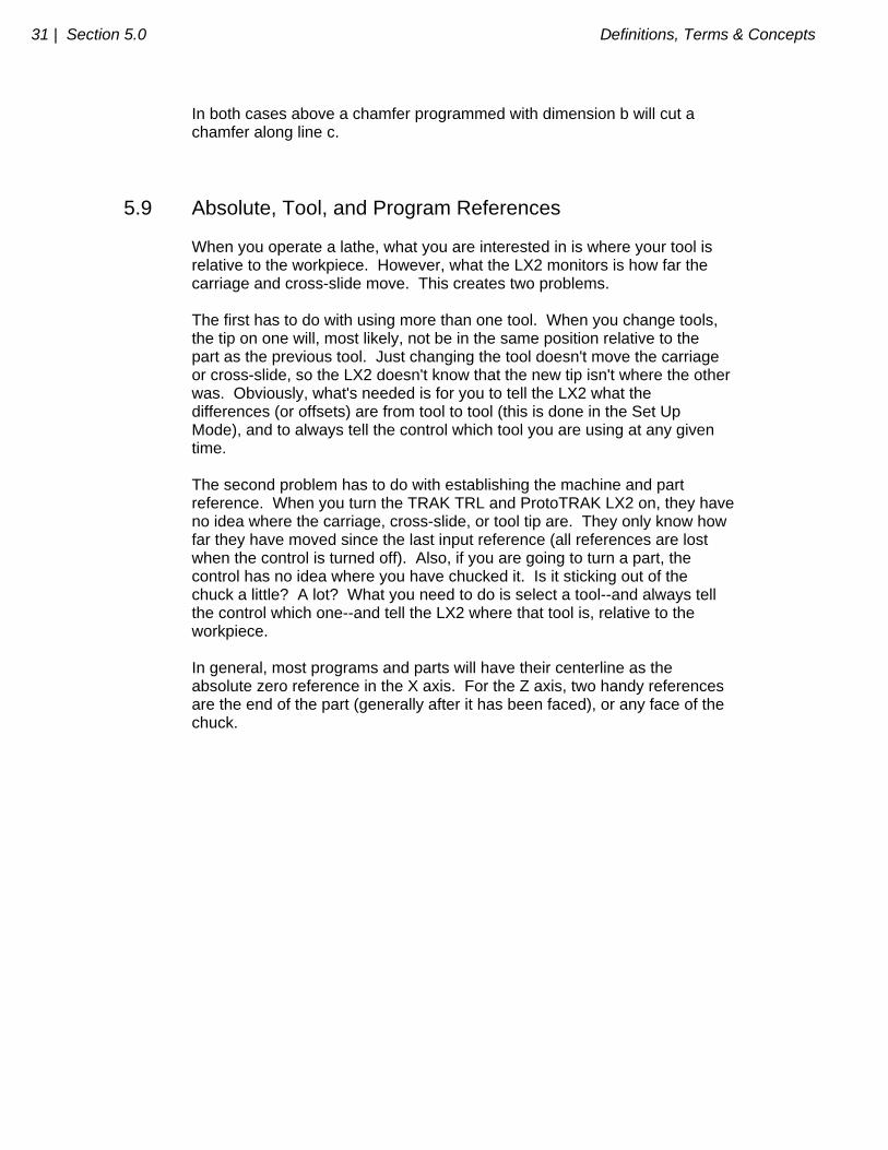
5.8 Chamfer The ProtoTRAK LX2 also allows for easy chamfer input. A chamfer may be programmed between two turn events, two arcs, or a turn and an arc.
i00221
k2
31 | Section 5.0 Definitions, Terms & Concepts
In both cases above a chamfer programmed with dimension b will cut a chamfer along line c.
5.9 Absolute, Tool, and Program References When you operate a lathe, what you are interested in is where your tool is relative to the workpiece. However, what the LX2 monitors is how far the carriage and cross-slide move. This creates two problems. The first has to do with using more than one tool. When you change tools, the tip on one will, most likely, not be in the same position relative to the part as the previous tool. Just changing the tool doesn't move the carriage or cross-slide, so the LX2 doesn't know that the new tip isn't where the other was. Obviously, what's needed is for you to tell the LX2 what the differences (or offsets) are from tool to tool (this is done in the Set Up Mode), and to always tell the control which tool you are using at any given time. The second problem has to do with establishing the machine and part reference. When you turn the TRAK TRL and ProtoTRAK LX2 on, they have no idea where the carriage, cross-slide, or tool tip are. They only know how far they have moved since the last input reference (all references are lost when the control is turned off). Also, if you are going to turn a part, the control has no idea where you have chucked it. Is it sticking out of the chuck a little? A lot? What you need to do is select a tool--and always tell the control which one--and tell the LX2 where that tool is, relative to the workpiece. In general, most programs and parts will have their centerline as the absolute zero reference in the X axis. For the Z axis, two handy references are the end of the part (generally after it has been faced), or any face of the chuck.
SECTION
____________ 6.0 ______________________ _____ DRO Mode
DRO Mode Section 6.0 | 33
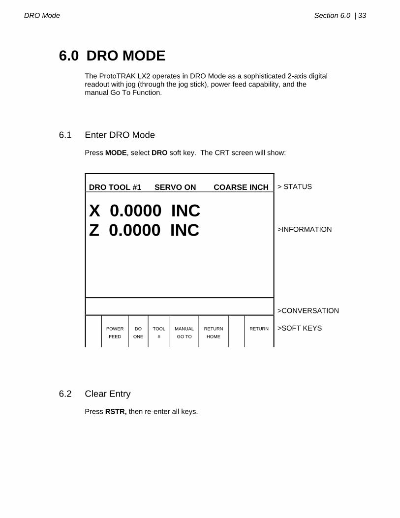
6.0 DRO MODE The ProtoTRAK LX2 operates in DRO Mode as a sophisticated 2-axis digital readout with jog (through the jog stick), power feed capability, and the manual Go To Function.
6.1 Enter DRO Mode Press MODE, select DRO soft key. The CRT screen will show:
DRO TOOL #1 SERVO ON COARSE INCH
> STATUS
X 0.0000 INC Z 0.0000 INC
>INFORMATION
>CONVERSATION
POWER
FEED
DO
ONE
TOOL
#
MANUAL
GO TO
RETURN
HOME
RETURN
>SOFT KEYS
6.2 Clear Entry Press RSTR, then re-enter all keys.
34 | Section 6.0 DRO Mode
6.3 Inch to MM or MM to Inch Press IN/MM and note CRT screen status line.
6.4 Reset One Axis Press X or Z, INC SET. This zeros the incremental position in the selected axis.
6.5 Preset Press X or Z, numeric data, INC SET to preset selected axis.
6.6 Reset Absolute Reference Press X or Z, ABS SET to set selected axis absolute to zero at the current position. See 6.8 and 6.9 to display this data. Note: This will also reset the incremental dimension if the absolute position is being displayed when it is reset.
6.7 Preset Absolute Reference Press X or Z, numeric data, ABS SET to set the selected axis absolute to a preset location for the current machine position. See 6.8 and 6.9 to display this data. Note: This will also reset the incremental dimension if the absolute position is being displayed when it is preset.
6.8 Recall Absolute Position of All Axes Press INC/ABS. Note the dimension for each axis is labeled INC or ABS.
DRO Mode Section 6.0 | 35
Press INC/ABS again to revert to the original reading.
6.9 Recall Absolute Position of One Axis Press X or Z, INC/ABS. Note the INC or ABS label for each axis. Repeat to get selected axis back to original reading.
6.10 Change From Fine to Coarse Handwheel Resolution and Feed Press the F/C key to switch back and forth from fine to coarse. Resolution Travel/Revolution X Fine .0001"/.005mm .02"/1mm Coarse .0005"/.02mm .10"/4mm Z Fine .0005"/.02mm .10"/4mm Coarse .002"/.05mm .40"/10mm
6.11 Tool Number As discussed in Section 5.8, it is always necessary to tell the ProtoTRAK LX2 which tool number you want to use. This is because you want the readout to represent where the tool tip is (which changes from tool to tool), not where the carriage and cross-slide are. Each time you change tools in the DRO mode, it is mandatory that you press the TOOL # soft key (the conversation line will show the current tool number), input the correct tool number and SET. Of course, it is also necessary that the LX2 know what the offset differences are from tool to tool which is explained in Section 9.2.
6.12 Power Feed The servo motors can be used as a power feed for the carriage or cross- slide. a. Press the PWR FEED soft key.

36 | Section 6.0 DRO Mode
b. The conversation line will read "Power Feed 10 ipm" indicating the status and feed rate. c. Press FEED or FEED to adjust the feedrate from 1 ipm to 100 ipm. d. Press X or Z, the dimension you wish to move to, and INC SET. e. Press GO to begin power feed. f. Press STOP to halt power feed for any reason. Press GO to resume. g. When the movement is complete, the system will revert to normal DRO operation.
6.13 Manual Go To The Manual Go To feature allows you to input an absolute position in X and/or Z, where the ProtoTRAK LX2 will disable the electronic handwheels and/or jog stick. In other words, it creates a barrier which the tool tip cannot move past. This allows you to move to a position without slowing way down to prevent overshoot. For example, in making several turning passes to a prescribed shoulder dimension. To input a Go To position, press the Manual Go To soft key. The conversation line will show the current X and Z Go To position or barrier. Press X or Z, the new position you wish, and SET. Move the axis with the handwheel or jog stick and it will automatically stop at the position. You may move in the opposite direction away from the Go To position.
6.14 Return to Home At any time during manual DRO operation you may automatically move the tool tip to your home location in X and Z by pressing the RETURN HOME soft key. When you do, the conversation line will read "Check Tool then press GO." Make sure your tool and its path is clear and press the GO key. When you do, the carriage and cross-slide will move at rapid speed to your X and Z home position. Home position is established in the Set Up Mode.
DRO Mode Section 6.0 | 37
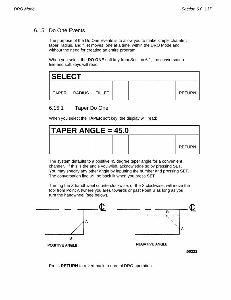
6.15 Do One Events The purpose of the Do One Events is to allow you to make simple chamfer, taper, radius, and fillet moves, one at a time, within the DRO Mode and without the need for creating an entire program. When you select the DO ONE soft key from Section 6.1, the conversation line and soft keys will read:
SELECT
TAPER
RADIUS
FILLET
RETURN
6.15.1 Taper Do One When you select the TAPER soft key, the display will read:
TAPER ANGLE = 45.0
RETURN
The system defaults to a positive 45 degree taper angle for a convenient chamfer. If this is the angle you wish, acknowledge so by pressing SET. You may specify any other angle by inputting the number and pressing SET. The conversation line will be back lit when you press SET Turning the Z handhweel counterclockwise, or the X clockwise, will move the tool from Point A (where you are), towards or past Point B as long as you turn the handwheel (see below).
i00223
Press RETURN to revert back to normal DRO operation.
38 | Section 6.0 DRO Mode
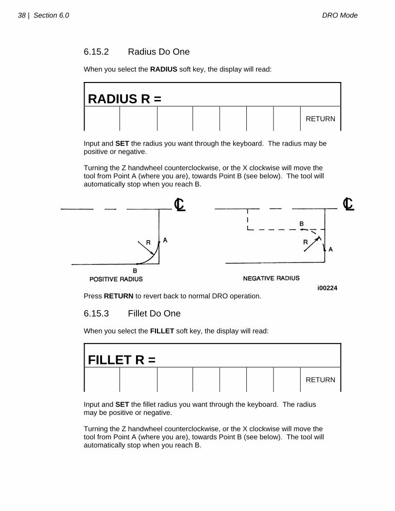
6.15.2 Radius Do One When you select the RADIUS soft key, the display will read:
RADIUS R =
RETURN
Input and SET the radius you want through the keyboard. The radius may be positive or negative. Turning the Z handwheel counterclockwise, or the X clockwise will move the tool from Point A (where you are), towards Point B (see below). The tool will automatically stop when you reach B.
i00224
Press RETURN to revert back to normal DRO operation.
6.15.3 Fillet Do One When you select the FILLET soft key, the display will read:
FILLET R =
RETURN
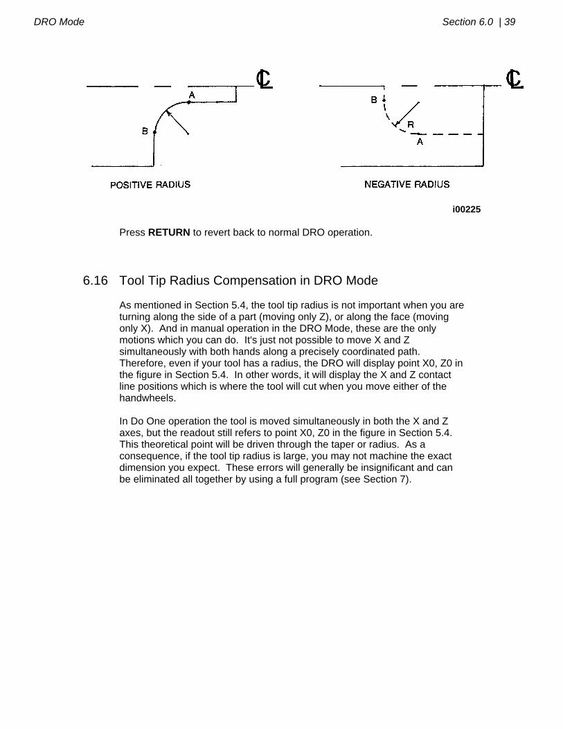
Input and SET the fillet radius you want through the keyboard. The radius may be positive or negative. Turning the Z handwheel counterclockwise, or the X clockwise will move the tool from Point A (where you are), towards Point B (see below). The tool will automatically stop when you reach B.
DRO Mode Section 6.0 | 39
i00225 Press RETURN to revert back to normal DRO operation.
6.16 Tool Tip Radius Compensation in DRO Mode As mentioned in Section 5.4, the tool tip radius is not important when you are turning along the side of a part (moving only Z), or along the face (moving only X). And in manual operation in the DRO Mode, these are the only motions which you can do. It's just not possible to move X and Z simultaneously with both hands along a precisely coordinated path. Therefore, even if your tool has a radius, the DRO will display point X0, Z0 in the figure in Section 5.4. In other words, it will display the X and Z contact line positions which is where the tool will cut when you move either of the handwheels. In Do One operation the tool is moved simultaneously in both the X and Z axes, but the readout still refers to point X0, Z0 in the figure in Section 5.4. This theoretical point will be driven through the taper or radius. As a consequence, if the tool tip radius is large, you may not machine the exact dimension you expect. These errors will generally be insignificant and can be eliminated all together by using a full program (see Section 7).
_________________________________________________________________ Southwestern Industries, Inc.
TRAK TRL & ProtoTRAK LX2 Programming, Operating & Care Manual
SECTION
____________ 7.0 _____________________________ Program Mode
41 | Section 7.0 Program Mode
7.0 PROGRAM MODE
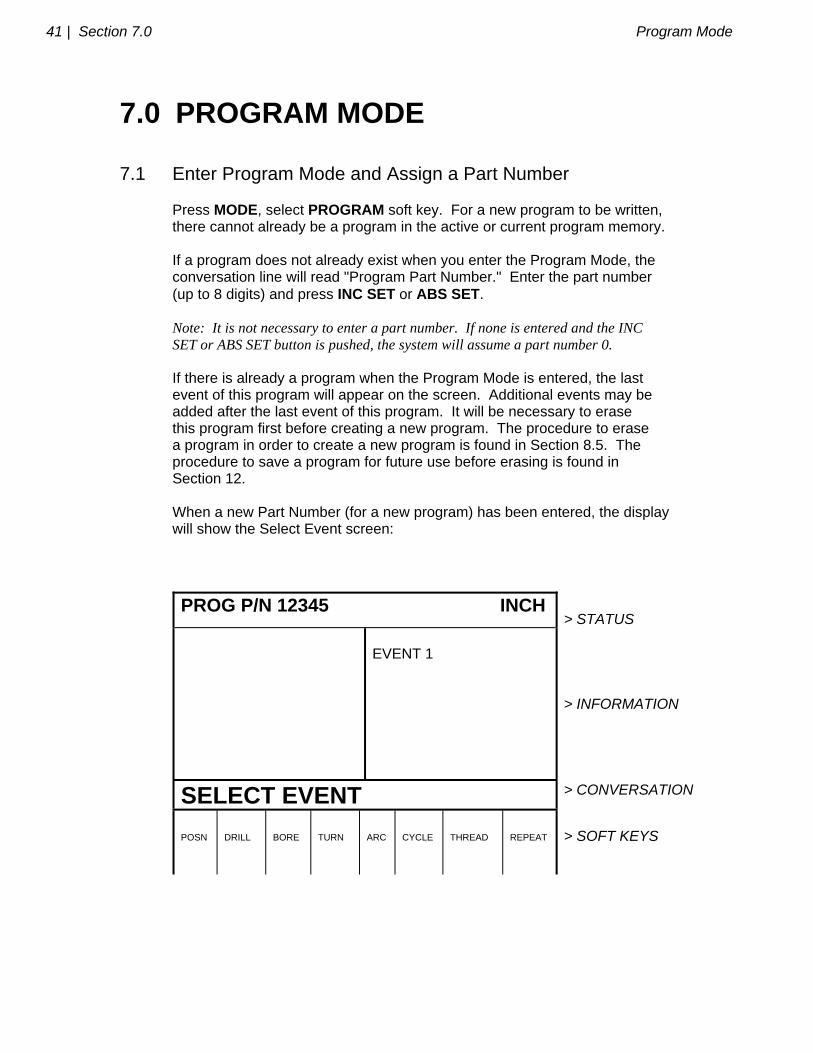
7.1 Enter Program Mode and Assign a Part Number Press MODE, select PROGRAM soft key. For a new program to be written, there cannot already be a program in the active or current program memory. If a program does not already exist when you enter the Program Mode, the conversation line will read "Program Part Number." Enter the part number (up to 8 digits) and press INC SET or ABS SET. Note: It is not necessary to enter a part number. If none is entered and the INC SET or ABS SET button is pushed, the system will assume a part number 0. If there is already a program when the Program Mode is entered, the last event of this program will appear on the screen. Additional events may be added after the last event of this program. It will be necessary to erase this program first before creating a new program. The procedure to erase a program in order to create a new program is found in Section 8.5. The procedure to save a program for future use before erasing is found in Section 12. When a new Part Number (for a new program) has been entered, the display will show the Select Event screen:
PROG P/N 12345 INCH
> STATUS
EVENT 1
> INFORMATION
SELECT EVENT > CONVERSATION
POSN
DRILL
BORE
TURN
ARC
CYCLE
THREAD
REPEAT
> SOFT KEYS
Program Mode Section 7.0 | 42
7.2 Incremental Reference Position When X and Z data for the beginning position of any event are input as incremental data, this increment must be measured from some known point in the previous event. Following are the positions for each event type from which the incremental moves are made in the subsequent event: POSITION: X and Z programmed DRILL: X = 0 ABS, Z FINAL and Z RAPID programmed BORE: X, Z FINAL, and Z RAPID programmed TURN: X END and Z END programmed ARC: X END and Z END programmed CYCLE: the last X and Z programmed REPEAT: The appropriate reference position for the event prior to the first event which was repeated. THREAD: The X END and Z END programmed For example, if an ARC event followed a TURN event, a 2.0 inch incremental Z BEG would mean that in the Z direction the beginning of the ARC event is 2.0 inches from the end of the TURN event.
7.3 Programming Strategy and Procedures The ProtoTRAK LX2 makes programming easy by allowing you to program the actual part geometry as defined by the print. The Select Event screen (7.1) is basically a list of all the types of geometry. The basic strategy is to select the soft key event type (geometry) and then follow all instructions in the conversation line. When an event is selected, all the prompts which need to be input will be shown on the right side of the information area. The first prompt will be highlighted and also shown in the conversation line. Input the dimension or data requested and press INC SET or ABS SET. For X or Z dimension data it is very important to properly select INC SET or ABS SET. For all other data either SET will do. As data is being entered it will show in the conversation line. When SET, the
43 | Section 7.0 Program Mode
data will be transferred to the information area, and the next prompt will be shown in the conversation line. You may press the DATA FWD or DATA BACK soft keys to go back to edit any data within an event. Simply shift forward or back to get the prompt in the conversation line and reinput the data. At any time before the event is complete you may cancel the event by pressing the ABORT EVENT soft key. When all data for an event has been entered, the entire event will be shifted to the left side of the screen and the conversation line will ask you to select the next event.
7.3.1 Assumed Tool Offset, Feedrate, and Tool # The ProtoTRAK LX2 will automatically program the following: TOOL OFFSET: for a Turn or Arc Event, same as the last event if that event was a Turn or Arc event FEEDRATE: same as last event if that event was a Turn, Arc, or Cycle TOOL #: same as last event You may change these assumed inputs by simply inputting the correct data when the event is programmed.
7.4 POSITION Events This event type positions the tool to the programmed position. The positioning is always at rapid speed (modified by feedrate override) and in the most direct path possible from the previous location. Position is most often used to move the tool away from the part so that when it rapids to a next non-connective event or home, it will not crash into the workpiece. To program a Position event press the POSN soft key on the Select Event screen (see Section 7.1). The following screen will appear:
Program Mode Section 7.0 | 44
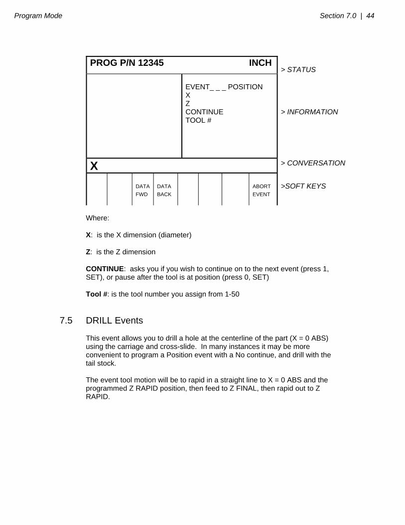
PROG P/N 12345 INCH > STATUS
EVENT_ _ _ POSITION X Z CONTINUE TOOL #
> INFORMATION
X > CONVERSATION
DATA
FWD
DATA
BACK
ABORT
EVENT
>SOFT KEYS
Where: X: is the X dimension (diameter) Z: is the Z dimension CONTINUE: asks you if you wish to continue on to the next event (press 1, SET), or pause after the tool is at position (press 0, SET) Tool #: is the tool number you assign from 1-50
7.5 DRILL Events This event allows you to drill a hole at the centerline of the part (X = 0 ABS) using the carriage and cross-slide. In many instances it may be more convenient to program a Position event with a No continue, and drill with the tail stock. The event tool motion will be to rapid in a straight line to X = 0 ABS and the programmed Z RAPID position, then feed to Z FINAL, then rapid out to Z RAPID.
45 | Section 7.0 Program Mode
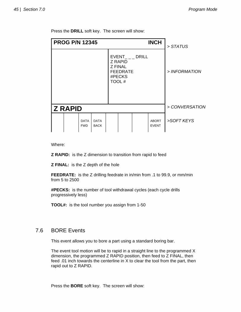
Press the DRILL soft key. The screen will show:
PROG P/N 12345 INCH > STATUS
EVENT_ _ _ DRILL Z RAPID Z FINAL FEEDRATE #PECKS TOOL #
> INFORMATION
Z RAPID > CONVERSATION
DATA
FWD
DATA
BACK
ABORT
EVENT
>SOFT KEYS
Where: Z RAPID: is the Z dimension to transition from rapid to feed Z FINAL: is the Z depth of the hole FEEDRATE: is the Z drilling feedrate in in/min from .1 to 99.9, or mm/min from 5 to 2500 #PECKS: is the number of tool withdrawal cycles (each cycle drills progressively less) TOOL#: is the tool number you assign from 1-50
7.6 BORE Events This event allows you to bore a part using a standard boring bar. The event tool motion will be to rapid in a straight line to the programmed X dimension, the programmed Z RAPID position, then feed to Z FINAL, then feed .01 inch towards the centerline in X to clear the tool from the part, then rapid out to Z RAPID. Press the BORE soft key. The screen will show:
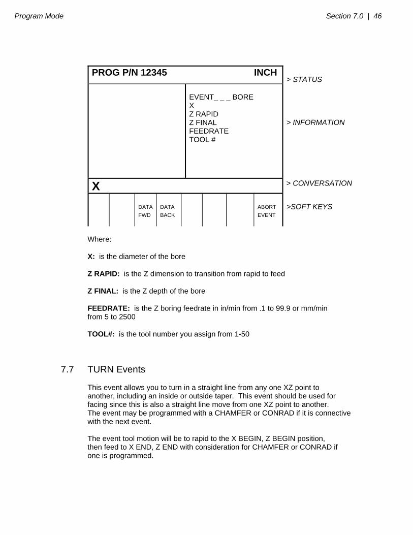
Program Mode Section 7.0 | 46
PROG P/N 12345 INCH > STATUS
EVENT_ _ _ BORE X Z RAPID Z FINAL FEEDRATE TOOL #
> INFORMATION
X > CONVERSATION
DATA
FWD
DATA
BACK
ABORT
EVENT
>SOFT KEYS
Where: X: is the diameter of the bore Z RAPID: is the Z dimension to transition from rapid to feed Z FINAL: is the Z depth of the bore FEEDRATE: is the Z boring feedrate in in/min from .1 to 99.9 or mm/min from 5 to 2500 TOOL#: is the tool number you assign from 1-50
7.7 TURN Events This event allows you to turn in a straight line from any one XZ point to another, including an inside or outside taper. This event should be used for facing since this is also a straight line move from one XZ point to another. The event may be programmed with a CHAMFER or CONRAD if it is connective with the next event. The event tool motion will be to rapid to the X BEGIN, Z BEGIN position, then feed to X END, Z END with consideration for CHAMFER or CONRAD if one is programmed.
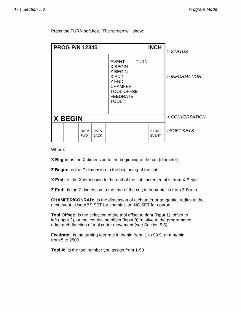
47 | Section 7.0 Program Mode
Press the TURN soft key. The screen will show:
PROG P/N 12345 INCH > STATUS
EVENT_ _ _ TURN X BEGIN Z BEGIN X END Z END CHAMFER TOOL OFFSET FEEDRATE TOOL #
> INFORMATION
X BEGIN > CONVERSATION
DATA
FWD
DATA
BACK
ABORT
EVENT
>SOFT KEYS
Where: X Begin: is the X dimension to the beginning of the cut (diameter) Z Begin: is the Z dimension to the beginning of the cut X End: is the X dimension to the end of the cut; incremental is from X Begin Z End: is the Z dimension to the end of the cut; incremental is from Z Begin CHAMFER/CONRAD: is the dimension of a chamfer or tangential radius to the next event. Use ABS SET for chamfer, or INC SET for conrad. Tool Offset: is the selection of the tool offset to right (input 1), offset to left (input 2), or tool center--no offset (input 0) relative to the programmed edge and direction of tool cutter movement (see Section 5.5) Feedrate: is the turning feedrate in in/min from .1 to 99.9, or mm/min from 5 to 2500 Tool #: is the tool number you assign from 1-50
Program Mode Section 7.0 | 48
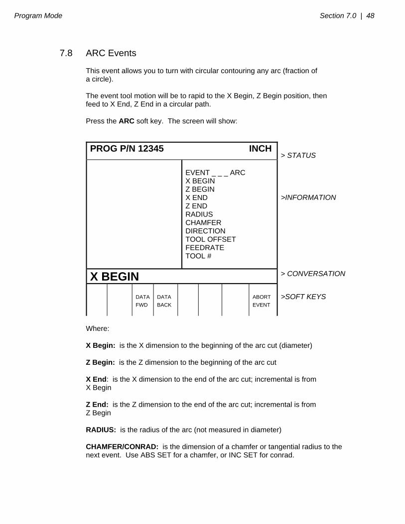
7.8 ARC Events This event allows you to turn with circular contouring any arc (fraction of a circle). The event tool motion will be to rapid to the X Begin, Z Begin position, then feed to X End, Z End in a circular path. Press the ARC soft key. The screen will show:
PROG P/N 12345 INCH > STATUS
EVENT _ _ _ ARC X BEGIN Z BEGIN X END Z END RADIUS CHAMFER DIRECTION TOOL OFFSET FEEDRATE TOOL #
>INFORMATION
X BEGIN > CONVERSATION
DATA
FWD
DATA
BACK
ABORT
EVENT
>SOFT KEYS
Where: X Begin: is the X dimension to the beginning of the arc cut (diameter) Z Begin: is the Z dimension to the beginning of the arc cut X End: is the X dimension to the end of the arc cut; incremental is from X Begin Z End: is the Z dimension to the end of the arc cut; incremental is from Z Begin RADIUS: is the radius of the arc (not measured in diameter) CHAMFER/CONRAD: is the dimension of a chamfer or tangential radius to the next event. Use ABS SET for a chamfer, or INC SET for conrad.
49 | Section 7.0 Program Mode
Direction: is the clockwise (input 1), or counterclockwise (input 2) direction of the arc looking down from the top Tool Offset: is the selection of the tool offset to right (input 1), offset to left (input 2), or tool center--no offset (input 0) relative to the programmed edge and direction of tool cutter movement (see Section 5.5) Feedrate: is the turning feedrate in in/min from .1 to 99.9, or mm/min from 5 to 2500 Tool #: is the tool number you assign from 1-50
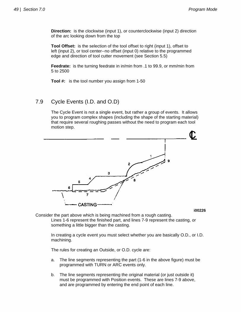
7.9 Cycle Events (I.D. and O.D) The Cycle Event is not a single event, but rather a group of events. It allows you to program complex shapes (including the shape of the starting material) that require several roughing passes without the need to program each tool motion step.
i00226
Consider the part above which is being machined from a rough casting. Lines 1-6 represent the finished part, and lines 7-9 represent the casting, or something a little bigger than the casting. In creating a cycle event you must select whether you are basically O.D., or I.D. machining. The rules for creating an Outside, or O.D. cycle are: a. The line segments representing the part (1-6 in the above figure) must be programmed with TURN or ARC events only. b. The line segments representing the original material (or just outside it) must be programmed with Position events. These are lines 7-9 above, and are programmed by entering the end point of each line.

Program Mode Section 7.0 | 50
c. The first line segment must be one representing the part ("a" above) not the original material ("b" above). d. The X End and Z End of the last segment must be the same as the X Begin and Z Begin of the first. In the example above, line segment 9 must end where line segment 1 begins. e. There may be no more than 20 line segments for any Cycle. f. The roughing and finishing tools for the Outside Cycle events must be right-hand turning tools (see Type 1 in Section 9). g. The lines which represent the part (1-6 in the above figure) can never move toward the centerline (decreasing X), or away from the chuck (increasing Z). Moves with no change in X or Z are okay. h. The lines which represent the original material or something a little bigger (lines 7-9 in the above figure) can never move away from the centerline (increasing X), or toward the chuck (decreasing Z). Moves with no change in X or Z are okay. The rules for creating an Inside, or I.D. cycle are: a.-e. Same as above for Outside cycles. f. The roughing and finishing tools for the Inside Cycle events must be boring tools (see Type 3 in Section 9). g. The lines which represent the finished part can never move away from the centerline (increasing X), or away from the chuck (increasing Z). Moves with no change in X or Z are okay. h. The lines which represent the original material or something a little bigger can never move toward the centerline (decreasing X), or toward the chuck (decreasing Z). Moves with no change in X or Z are okay. The event tool motion depends on whether you select to rough the material with successive turning passes (Z motion with constant X), or facing passes (X motion with constant Z). If you choose turning, the tool will rapid to a point at the programmed material--a point along line 8 in the figure above. Then the tool will feed at a constant X position across until it nears one of the part lines leaving enough material for the programmed finish cut. This is repeated until the part is completely roughed. Then the tool will feed along the part lines standing off an amount equal to the finish cut. Then the carriage will move to home and call out the finish tool. This tool will rapid to the beginning of the first line and turn the part to its final dimension.
51 | Section 7.0 Program Mode
Press the CYCLE soft key. The screen will show:
PROG P/N 12345 INCH > STATUS
EVENT _ _ _ CYCLE SIDE # OF PASSES APPROACH FEEDRATE TOOL # FIN CUT FIN FEEDRATE FIN TOOL #
> INFORMATION
0=inside, 1=outside: > CONVERSATION
DATA
FWD
DATA
BACK
ABORT
EVENT
>SOFT KEYS
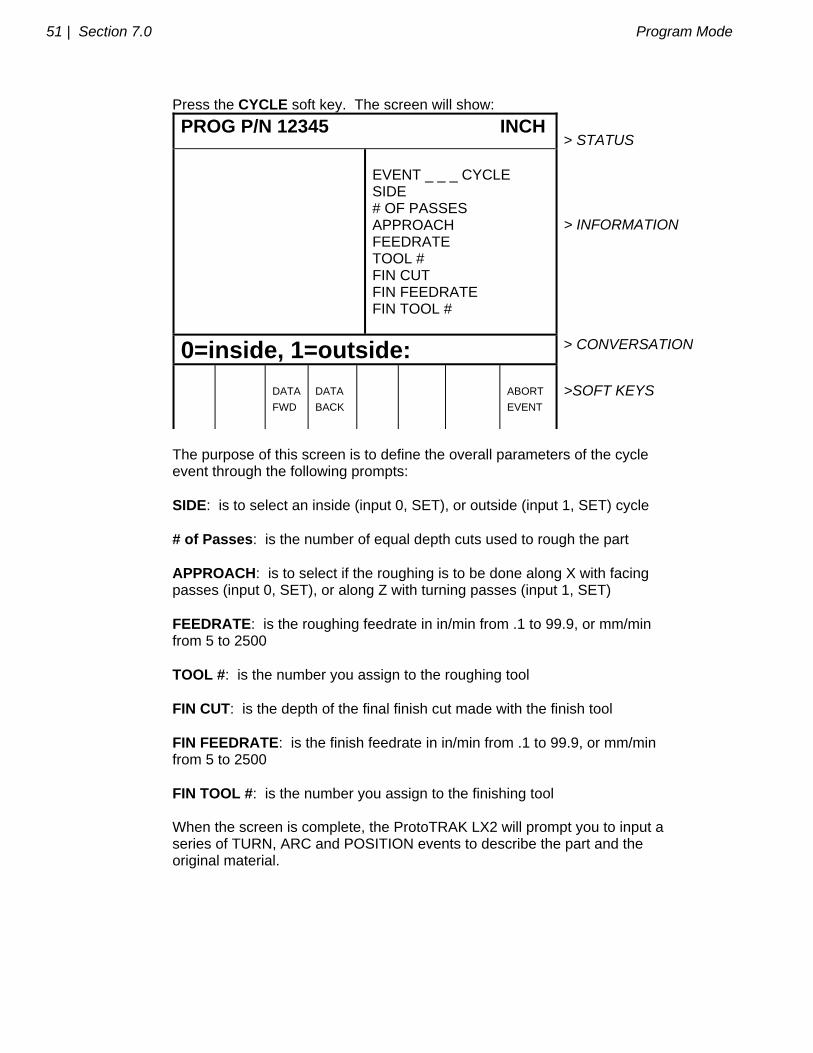
The purpose of this screen is to define the overall parameters of the cycle event through the following prompts: SIDE: is to select an inside (input 0, SET), or outside (input 1, SET) cycle # of Passes: is the number of equal depth cuts used to rough the part APPROACH: is to select if the roughing is to be done along X with facing passes (input 0, SET), or along Z with turning passes (input 1, SET) FEEDRATE: is the roughing feedrate in in/min from .1 to 99.9, or mm/min from 5 to 2500 TOOL #: is the number you assign to the roughing tool FIN CUT: is the depth of the final finish cut made with the finish tool FIN FEEDRATE: is the finish feedrate in in/min from .1 to 99.9, or mm/min from 5 to 2500 FIN TOOL #: is the number you assign to the finishing tool When the screen is complete, the ProtoTRAK LX2 will prompt you to input a series of TURN, ARC and POSITION events to describe the part and the original material.
Program Mode Section 7.0 | 52
The first screen will have the soft keys:
SELECT
TURN
ARC
ABORT EVENT
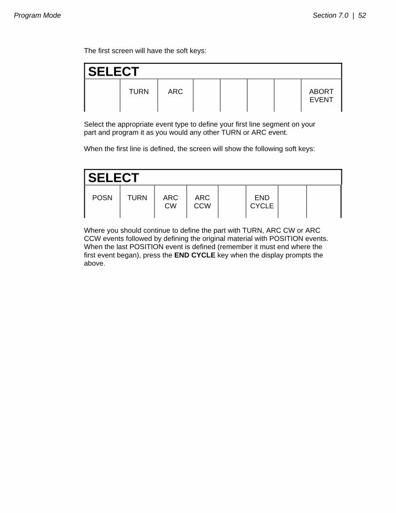
Select the appropriate event type to define your first line segment on your part and program it as you would any other TURN or ARC event. When the first line is defined, the screen will show the following soft keys:
SELECT
POSN
TURN
ARC CW
ARC CCW
END
CYCLE
Where you should continue to define the part with TURN, ARC CW or ARC CCW events followed by defining the original material with POSITION events. When the last POSITION event is defined (remember it must end where the first event began), press the END CYCLE key when the display prompts the above.
53 | Section 7.0 Program Mode
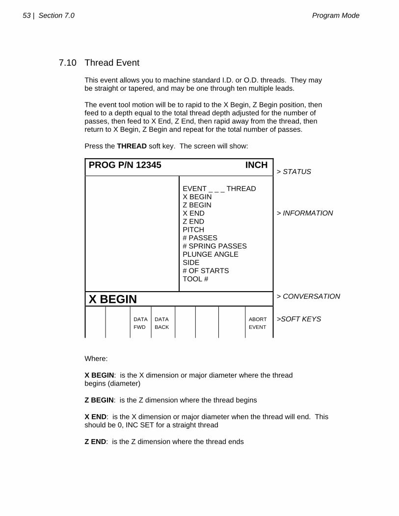
7.10 Thread Event This event allows you to machine standard I.D. or O.D. threads. They may be straight or tapered, and may be one through ten multiple leads. The event tool motion will be to rapid to the X Begin, Z Begin position, then feed to a depth equal to the total thread depth adjusted for the number of passes, then feed to X End, Z End, then rapid away from the thread, then return to X Begin, Z Begin and repeat for the total number of passes. Press the THREAD soft key. The screen will show:
PROG P/N 12345 INCH > STATUS
EVENT _ _ _ THREAD X BEGIN Z BEGIN X END Z END PITCH # PASSES # SPRING PASSES PLUNGE ANGLE SIDE # OF STARTS TOOL #
> INFORMATION
X BEGIN > CONVERSATION
DATA
FWD
DATA
BACK
ABORT
EVENT
>SOFT KEYS
Where: X BEGIN: is the X dimension or major diameter where the thread begins (diameter) Z BEGIN: is the Z dimension where the thread begins X END: is the X dimension or major diameter when the thread will end. This should be 0, INC SET for a straight thread Z END: is the Z dimension where the thread ends
Program Mode Section 7.0 | 54
PITCH: is the distance from one thread to the next in inches or mm. It is equal to one divided by the number of threads per inch. For example, the pitch for a 1/4-20 screw is 1 divided by 20 = .05 inches. # PASSES: is the number of passes (1-99) to cut the thread to its final depth (excludes spring passes) # SPRING PASSES: is the number of passes (0-99) at the final depth PLUNGE ANGLE: is the angle the tool feeds into the beginning depth. The default 29.5 degrees is recommended SIDE: selects whether this is an I.D. (input 0,SET), or O.D. (input 1,SET) thread # STARTS: selects whether the thread is single lead (input SET or 1,SET), double lead (input 2,SET), triple lead (input 3,SET), etc. (up to 10 leads) TOOL #: is the tool number you assign from 1-50
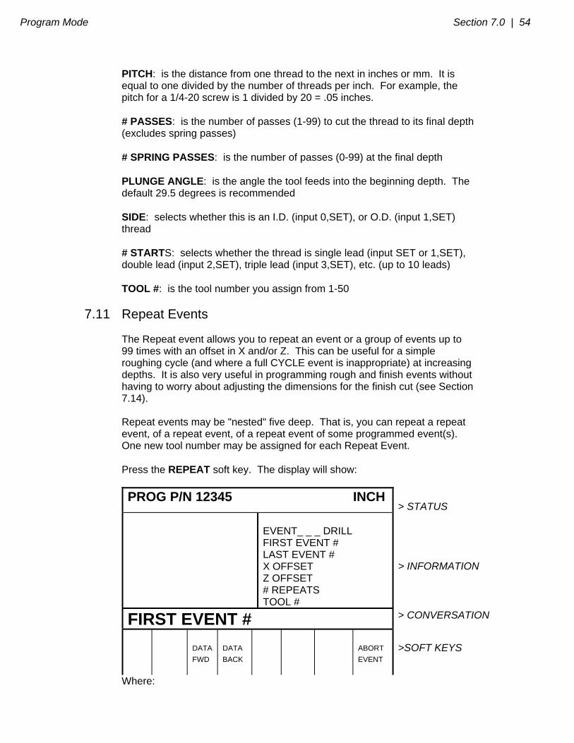
7.11 Repeat Events The Repeat event allows you to repeat an event or a group of events up to 99 times with an offset in X and/or Z. This can be useful for a simple roughing cycle (and where a full CYCLE event is inappropriate) at increasing depths. It is also very useful in programming rough and finish events without having to worry about adjusting the dimensions for the finish cut (see Section 7.14). Repeat events may be "nested" five deep. That is, you can repeat a repeat event, of a repeat event, of a repeat event of some programmed event(s). One new tool number may be assigned for each Repeat Event. Press the REPEAT soft key. The display will show:
PROG P/N 12345 INCH > STATUS
EVENT_ _ _ DRILL FIRST EVENT # LAST EVENT # X OFFSET Z OFFSET # REPEATS TOOL #
> INFORMATION
FIRST EVENT # > CONVERSATION
DATA
FWD
DATA
BACK
ABORT
EVENT
>SOFT KEYS
Where:
55 | Section 7.0 Program Mode
FIRST EVENT #: is the event number of the first event to be repeated LAST EVENT #: is the event number of the last event to be repeated; if only one event is to be repeated, the Last Event # is the same as the First Event # X OFFSET: is the incremental X offset from event to be repeated (diameter) Z OFFSET: is the incremental Z offset from event to be repeated # REPEATS: is the number of times events are to be repeated up to 99 TOOL #: is the tool number you assign from 1-50
7.12 Aborting a Partially Programmed Event If you wish to not program an event (or start over) after you have started to program, press the ABORT EVENT soft key. The screen will show the "Select Event" screen as described in Section 7.1. Re-select the event type or another.
7.13 Editing Data While Programming an Event All data is entered by pressing the appropriate numeric keys and pressing INC SET or ABS SET. If you enter an incorrect number before you press INC SET or ABS SET you may clear the number by pressing RSTR (Restore). Then, input the correct number and press SET. If incorrect data has been entered and SET, you may correct it as long as you are still programming that same event. Press the DATA BACK or DATA FWD (Forward) soft key until the incorrect prompt and data are highlighted and shown in the conversation line. Enter the correct number and SET. The ProtoTRAK LX2 will not allow you to skip past prompts (by pressing DATA FWD) which need to be entered to complete an event. Previous events may be edited in the Edit Mode (see Section 8).

Program Mode Section 7.0 | 56
7.14 Finish Cuts The Cycle event is designed with a built-in finish cut routine. You may, however, want to program a roughing cut and a finish cut on a part which has been defined by BORE, TURN, and ARC events. The hard way to do this is to adjust all the X and Z dimensions (this is especially tricky for arcs) for the roughing cut, then program the correct part dimensions for the finish cut. The easy way is to use the following technique: a. Program the actual part shape and ignore the need to leave material for a finish cut. b. Use one Repeat event to repeat all the events in "a" above, but call out a different tool number even if you are actually using the same tool. c. In Set-Up Mode input an XMOD and ZMOD for the tool in the events programmed in "a" above that is equal to the finish cut material you wish to leave. See Section 9 for how to input this data. d. In Set-Up Mode make NO special adjustment to XMOD or ZMOD for the tool programmed in the Repeat event in "b" above. When the part is being run the XMOD and ZMOD from "c" will command the tool to stay away by this amount when the events from "a" are machined. However, when these events are repeated from "b", the correct dimensions will be cut on the part.
57 | Section 7.0 Program Mode
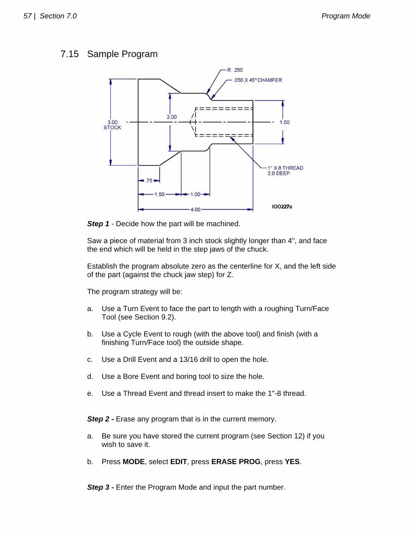
7.15 Sample Program
Step 1 - Decide how the part will be machined. Saw a piece of material from 3 inch stock slightly longer than 4", and face the end which will be held in the step jaws of the chuck. Establish the program absolute zero as the centerline for X, and the left side of the part (against the chuck jaw step) for Z. The program strategy will be: a. Use a Turn Event to face the part to length with a roughing Turn/Face Tool (see Section 9.2). b. Use a Cycle Event to rough (with the above tool) and finish (with a finishing Turn/Face tool) the outside shape. c. Use a Drill Event and a 13/16 drill to open the hole. d. Use a Bore Event and boring tool to size the hole. e. Use a Thread Event and thread insert to make the 1"-8 thread. Step 2 - Erase any program that is in the current memory. a. Be sure you have stored the current program (see Section 12) if you wish to save it. b. Press MODE, select EDIT, press ERASE PROG, press YES. Step 3 - Enter the Program Mode and input the part number.
Program Mode Section 7.0 | 58
Step 4 - Select TURN and input the following data to face the part for Event 1: X Begin 3.1 abs Z Begin 4.0 abs X End 0 abs Z End 0 inc (or 4.0 abs set) Chamfer set (a 0 is not required) Tool Offset 1 for Right Feedrate 5. Tool # 1 Step 5 - Create the program for the outside profile by inputting the following data: a. Press CYCLE to define the overall parameters and input for Event 2: Side 1 # of Passes 10 Approach 1 for Z Feedrate 5. Tool # 1 Fin Cut .02 Fin Feedrate 5. Fin Tool # 2 b. Press TURN to define the 1.5 O.D. and chamfer to the next event and input for Event 3: X End 0 inc Z End 2.5 abs Chamfer .05 abs set c. Press ARC CW to define the .25 radius arc and input for Event 4: X End 2.0 abs Z End -.25 inc Radius .25 Chamfer abs set d. Press TURN to define the 2.0 O.D. and input for Event 5: X End 0 inc Z End 1.5 abs Chamfer abs set e. Press TURN to define the taper and input for Event 6: X End 3.0 abs Z End .75 abs Chamfer abs set f. Press POSN (position) to define the O.D. of the original stock and input for Event 7: X End 3.0 abs
59 | Section 7.0 Program Mode
Z End 4.0 abs g. Press POSN to define the right side end of the material and position you back to the X Begin and Z Begin where you started (b) and input for Event 8: X End 1.5 abs Z End 4.0 abs h. Press END CYCLE to declare the end of the cycle event group of events. Step 6 - Select DRILL and input the following data to drill a 13/16 (.8125) hole for Event 9: Z Rapid 4.1 abs Z Final 1.7 abs (drill .3 farther to compensate for tip) Feedrate 2. # Pecks 5 Tool # 3
Step 7 - Select BORE to size hole to .875 (the minor diameter) and input for Event 10:
X .875 abs Z Rapid 4.1 abs Z Final 1.95 abs (a little clearance for the thread insert) Z Feedrate 3. Tool # 4 Step 8 - Select THREAD to program the 1"-8 thread 2.0 inch deep and input for Event 11: X Begin 1.0 abs (the major diameter) Z Begin 4.1 abs X End 0 inc (no taper) Z End 2.0 abs Pitch .1 # of Passes 6 # of Spring Passes 2 Plunge Angle 29.5 (use recommended default) Side 0 for inside # of Starts 1 (this is a single lead thread) Tool # 5 Step 9 - Enter the Set-Up Mode (see Section 9) and select SET HOME. Press X, 4., ABS SET and Z, 6., ABS SET to identify a point well off the part where the tool will go at Run start, tool change, and Run End. Press RETURN, MODE, DRO.
Program Mode Section 7.0 | 60
Step 10 - Load the part into the chuck. In the DRO Mode and with a facing tool, take a skin cut on the face of the part so that you have a consistent and flat surface to touch-off your tools. Use a micrometer or vernier to measure the part diameter and length. Press MODE, SET UP, TOOL SET UP. Step 11 - Configure Tool # 1 (the roughing turn/face tool). a. Mount the tool into its holder and mount on the tool post. b. Press 1, SET. c. Press SET NEW. d. Press 1, SET because Tool #1 is a right-hand turn/face tool. e. Using the handwheels, move the tool so that it touches the side of the part as shown by the SET X line on the ProtoTRAK screen diagram. f. Input the part diameter (say 3.004), ABS SET. g. Move the tool so that it touches the face of the part as shown by the SET Z line on the screen. h. Input the length of the part (say 4.073), ABS SET or you may input 0, ABS SET. i. Input the tool tip radius and SET. If you are using inserts, this radius will be shown on the box. j. Ignore XMOD and ZMOD for now. k. Press RETURN. Step 12 - Configure Tool #2 (the finish turn/face tool). a. Mount the tool as in Step 11. b. Press 2, SET. c. Press SET NEW. d. Press 1, SET because Tool #1 is a right-hand turn/face tool. e-k. Follow the directions in Step 11 being sure in (h) to touch off the same place and input the same dimension as you used before. Step 13 - Configure Tool #3 (the 13/16 drill). a. Follow the same pattern as above, inputting Tool #3 and selecting Drill (5). b. For setting X, touch the side of the drill to the side of the part nearest
61 | Section 7.0 Program Mode
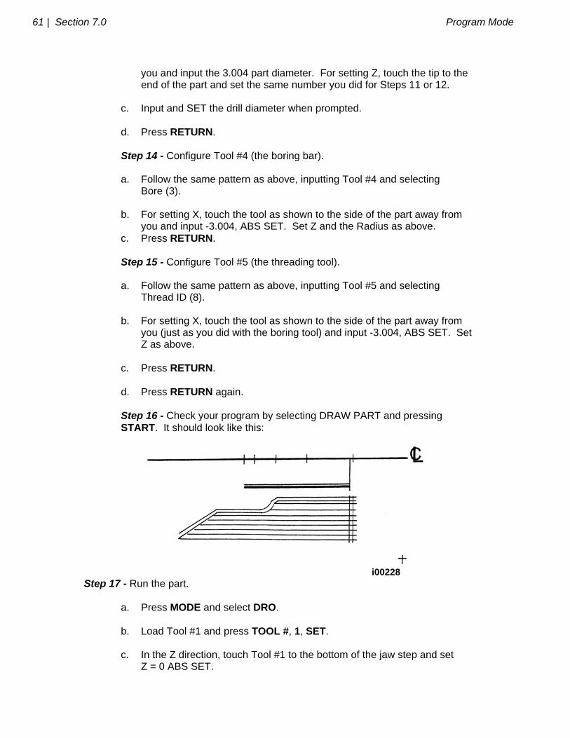
you and input the 3.004 part diameter. For setting Z, touch the tip to the end of the part and set the same number you did for Steps 11 or 12. c. Input and SET the drill diameter when prompted. d. Press RETURN. Step 14 - Configure Tool #4 (the boring bar). a. Follow the same pattern as above, inputting Tool #4 and selecting Bore (3). b. For setting X, touch the tool as shown to the side of the part away from you and input -3.004, ABS SET. Set Z and the Radius as above. c. Press RETURN. Step 15 - Configure Tool #5 (the threading tool). a. Follow the same pattern as above, inputting Tool #5 and selecting Thread ID (8). b. For setting X, touch the tool as shown to the side of the part away from you (just as you did with the boring tool) and input -3.004, ABS SET. Set Z as above. c. Press RETURN. d. Press RETURN again. Step 16 - Check your program by selecting DRAW PART and pressing START. It should look like this:
i00228
Step 17 - Run the part. a. Press MODE and select DRO. b. Load Tool #1 and press TOOL #, 1, SET. c. In the Z direction, touch Tool #1 to the bottom of the jaw step and set Z = 0 ABS SET.
Program Mode Section 7.0 | 62
d. Load a part and measure its diameter. e. Touch Tool #1 to the side of the part and set X = 3.004 ABS SET (or the diameter you measured in [d] above). f. Press MODE, and select RUN. g. Press START. The carriage will rapid so that Tool #1 is at home (X=4., Z=6.). h. Start the spindle at an appropriate RPM. Note all feeds in the program assume an aluminum part. Adjust if necessary. i. Press TRAKING. j. Turn the Z handwheel counterclockwise and machine the first part. k. If you wish to run in pure CNC instead of TRAKING, press STOP, CNC RUN, GO. Step 18 - Correcting the program to get a more accurate part. It is difficult in Tool Set Up, Steps 11-15, to touch off the part with necessary precision. As a consequence, your part dimensions may not be exactly to print. To correct, or "tweak" a program: a. Run and then measure the first part. b. Enter Set Up Mode and Select TOOL SET UP. c. Enter the tool number that created the inaccurate cut. Select EDIT. d. Press DATA FWD to XMOD or ZMOD. Input the dimension equal to the part error. Remember a plus XMOD makes the diameter bigger, and a plus ZMOD makes the part longer. e. Re-run the part. f. If you can't risk ruining the first part, input a plus (for O.D.), or minus (for I.D.) .02 XMOD and ZMOD for every tool. Then run the part, measure your errors, adjust the XMOD and ZMOD, and re-run.

_________________________________________________________________ Southwestern Industries, Inc.
TRAK TRL & ProtoTRAK LX2 Programming, Operating & Care Manual
SECTION
____________ 8.0 _____________________________ Edit Mode
64 | Section 8.0 Edit Mode
8.0 EDIT MODE The ProtoTRAK LX2 allows for complete editing of programs including the recall (and correction) of data, adding events in the middle of a program, deleting events within the program, and erasing programs.
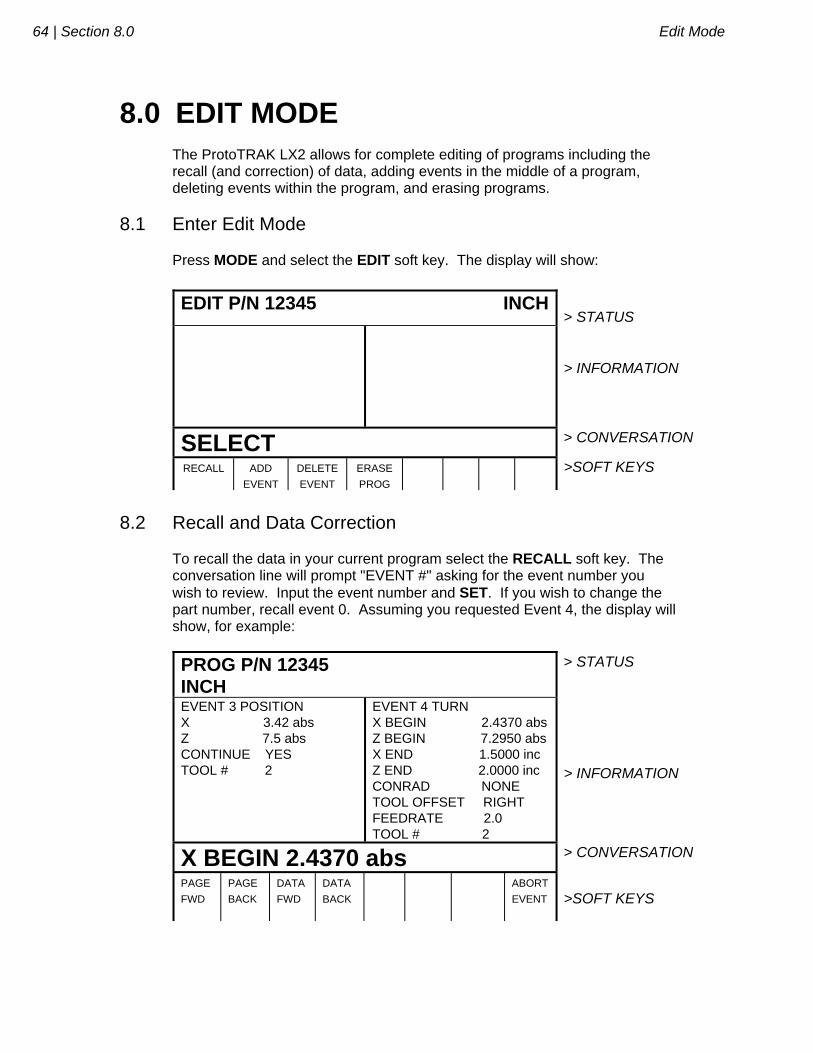
8.1 Enter Edit Mode Press MODE and select the EDIT soft key. The display will show:
EDIT P/N 12345 INCH
> STATUS
> INFORMATION
SELECT > CONVERSATION
RECALL ADD
EVENT
DELETE
EVENT
ERASE
PROG
>SOFT KEYS
8.2 Recall and Data Correction To recall the data in your current program select the RECALL soft key. The conversation line will prompt "EVENT #" asking for the event number you wish to review. Input the event number and SET. If you wish to change the part number, recall event 0. Assuming you requested Event 4, the display will show, for example:
PROG P/N 12345 INCH
> STATUS
EVENT 3 POSITION X 3.42 abs Z 7.5 abs CONTINUE YES TOOL # 2
EVENT 4 TURN X BEGIN 2.4370 abs Z BEGIN 7.2950 abs X END 1.5000 inc Z END 2.0000 inc CONRAD NONE TOOL OFFSET RIGHT FEEDRATE 2.0 TOOL # 2
> INFORMATION
X BEGIN 2.4370 abs > CONVERSATION
PAGE
FWD
PAGE
BACK
DATA
FWD
DATA
BACK
ABORT
EVENT
>SOFT KEYS
Edit Mode Section 8.0 | 65
Where: The event you recalled is shown with its data on the right side of the information area. The previous event is shown to the left. The conversation line shows the first prompt for the selected event. The PAGE FWD (Forward) soft key indexes the event forward by one (from 3 and 4, to 4 and 5 in the above example). The PAGE BACK soft key indexes the event back by one (from 3 and 4, to 2 and 3 in the above example). The DATA FWD (Forward) soft key steps the highlight and conversation line to the next prompt and data (Z Begin 7.2950A in the above example). The DATA BACK soft key steps the highlight and conversation line to the previous prompt. The EVENT # soft key allows you to input and recall another event without repeatedly paging. The RETURN soft key brings you back to the screen shown in Section 8.1. To correct any data, use the EVENT #, PAGE and DATA soft keys to get the data you wish to correct into the conversation line. Re-input and SET the correct data. Note: If the Feedrate is edited in any event it will automatically be edited in every subsequent and contiguous event with the same Tool number and feedrate. For example, let's say events 5 through 10, and 13 through 16 were all programmed with tool number 2, and 5 inches per minute feedrate. If you edit the feedrate in Event 7 to 3 inches per minute, it will automatically change Events 8, 9, and 10 also. Events 5, 6, 13, 14, 15, and 16 will not be affected. If you request Event 0, the status line will prompt for a new program part number. It may be changed if you wish by inputting the new number and pressing SET.
66 | Section 8.0 Edit Mode
8.3 Adding an Event Events may be added to the program at the beginning, middle, or end of the program one at a time. To do so, press the ADD EVENT soft key from the screen shown in Section 8.1. The conversation line will state "After Event #." Input the event number which the event you wish to add will follow and press SET. The screen will ask you to "Select Event," and program as you normally would (as described in Section 7). When an event has been added, all subsequent events will be renumbered accordingly. Appropriate adjustments will automatically be made to Repeat events.
8.4 Deleting an Event Events may be deleted one at a time or in continuous groups. To do so, press the DELETE EVENT soft key from the screen shown in Section 8.1. The conversation line will state "Delete From #." Input the first event number of the group to be deleted, and press SET. The conversation line will then read "Delete to #" asking you to input the last event number of the group to be deleted, and press SET. If only one event is to be deleted, input its event number for both "Delete From #" and "Delete To #." When an event or group of events have been deleted, all subsequent events will be renumbered to eliminate any number gaps. All event numbers in any Repeat event will also be renumbered.
8.5 Erasing a Program You may erase your current program by pressing the ERASE PROG soft key shown in the screen in Section 8.1. However, if you ever wish to reuse this program, you must be certain that it has been saved on the ProtoTRAK LX2 floppy disk memory, or saved offline (see Section 12). When you press the ERASE PROG soft key, the conversation line will be highlighted and state "ARE YOU SURE YOU WISH TO ERASE THIS PROGRAM?". If you are, press the YES soft key. If you are not, press the NO soft key. The display will return to the Select Mode screen.
_________________________________________________________________ Southwestern Industries, Inc.
TRAK TRL & ProtoTRAK LX2 Programming, Operating & Care Manual
SECTION
____________ 9.0 _____________________________ Set Up Mode
Set Up Mode Section 9.0 | 68
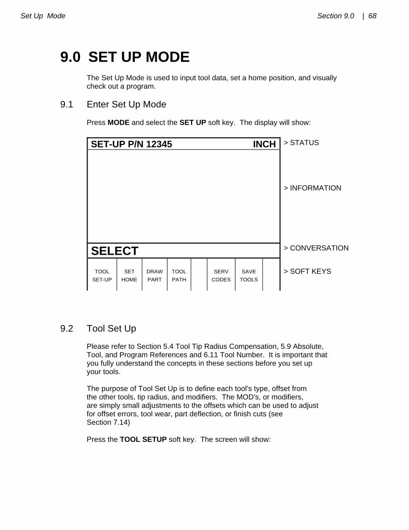
9.0 SET UP MODE The Set Up Mode is used to input tool data, set a home position, and visually check out a program.
9.1 Enter Set Up Mode Press MODE and select the SET UP soft key. The display will show:
SET-UP P/N 12345 INCH > STATUS
> INFORMATION
SELECT > CONVERSATION
TOOL
SET-UP
SET
HOME
DRAW
PART
TOOL
PATH
SERV
CODES
SAVE
TOOLS
> SOFT KEYS
9.2 Tool Set Up Please refer to Section 5.4 Tool Tip Radius Compensation, 5.9 Absolute, Tool, and Program References and 6.11 Tool Number. It is important that you fully understand the concepts in these sections before you set up your tools. The purpose of Tool Set Up is to define each tool's type, offset from the other tools, tip radius, and modifiers. The MOD's, or modifiers, are simply small adjustments to the offsets which can be used to adjust for offset errors, tool wear, part deflection, or finish cuts (see Section 7.14) Press the TOOL SETUP soft key. The screen will show:
69 | Section 9.0 Set Up Mode
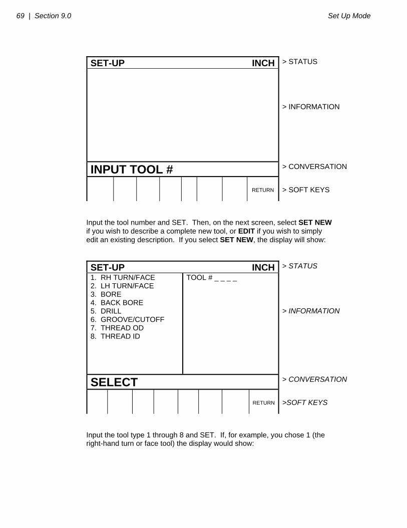
SET-UP INCH > STATUS
> INFORMATION
INPUT TOOL # > CONVERSATION
RETURN
> SOFT KEYS
Input the tool number and SET. Then, on the next screen, select SET NEW if you wish to describe a complete new tool, or EDIT if you wish to simply edit an existing description. If you select SET NEW, the display will show:
SET-UP INCH > STATUS
1. RH TURN/FACE 2. LH TURN/FACE 3. BORE 4. BACK BORE 5. DRILL 6. GROOVE/CUTOFF 7. THREAD OD 8. THREAD ID
TOOL # _ _ _ _
> INFORMATION
SELECT > CONVERSATION
RETURN
>SOFT KEYS
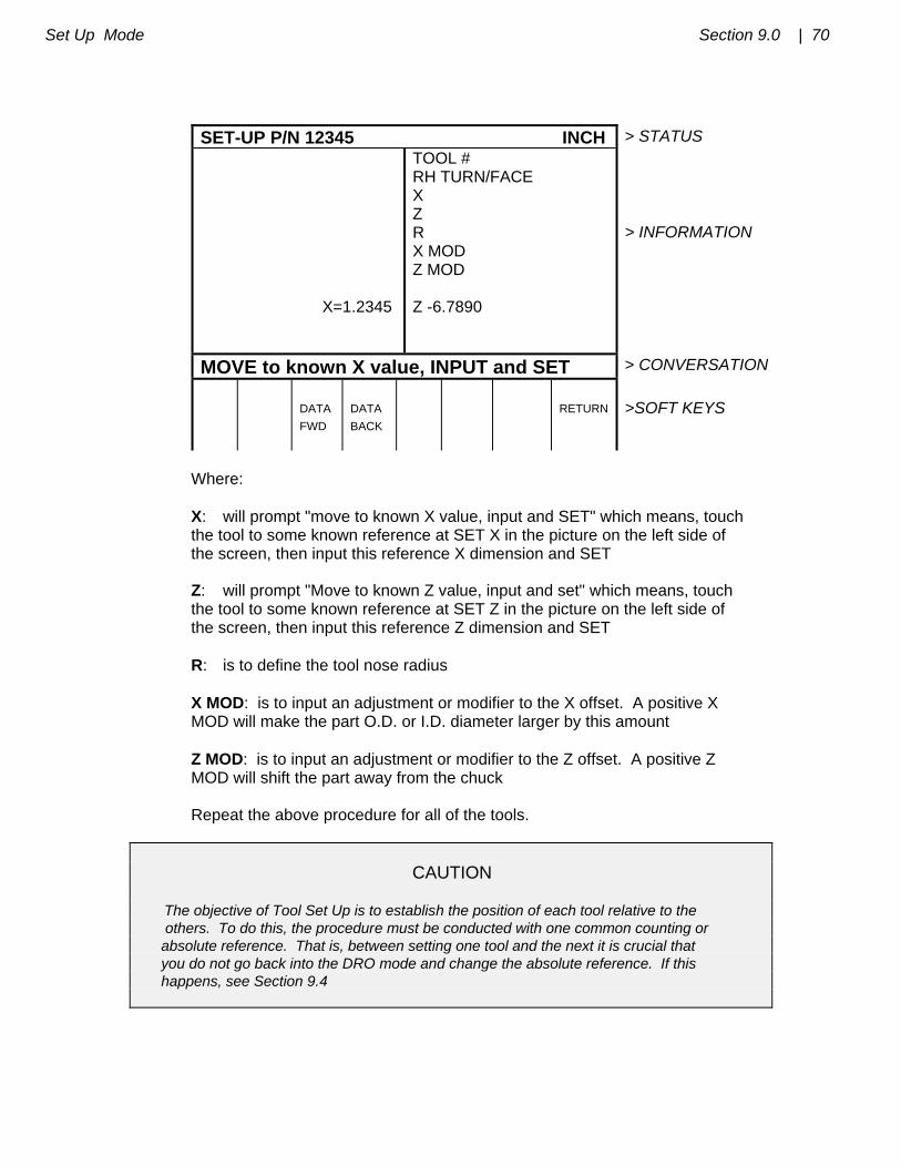
Input the tool type 1 through 8 and SET. If, for example, you chose 1 (the right-hand turn or face tool) the display would show:
Set Up Mode Section 9.0 | 70
SET-UP P/N 12345 INCH > STATUS X=1.2345
TOOL # RH TURN/FACE X Z R X MOD Z MOD Z -6.7890
> INFORMATION
MOVE to known X value, INPUT and SET > CONVERSATION
DATA
FWD
DATA
BACK
RETURN
>SOFT KEYS
Where: X: will prompt "move to known X value, input and SET" which means, touch the tool to some known reference at SET X in the picture on the left side of the screen, then input this reference X dimension and SET
Z: will prompt "Move to known Z value, input and set" which means, touch the tool to some known reference at SET Z in the picture on the left side of the screen, then input this reference Z dimension and SET R: is to define the tool nose radius X MOD: is to input an adjustment or modifier to the X offset. A positive X MOD will make the part O.D. or I.D. diameter larger by this amount Z MOD: is to input an adjustment or modifier to the Z offset. A positive Z MOD will shift the part away from the chuck Repeat the above procedure for all of the tools. CAUTION The objective of Tool Set Up is to establish the position of each tool relative to the others. To do this, the procedure must be conducted with one common counting or absolute reference. That is, between setting one tool and the next it is crucial that you do not go back into the DRO mode and change the absolute reference. If this happens, see Section 9.4
71 | Section 9.0 Set Up Mode
9.3 A Practical Technique for Accurate Tool Setting The problem with setting tools as described in Section 9.2 above is that it is generally not possible to touch a tool off with high precision. Furthermore, under real cutting conditions the tool, part and machine deflect a little so that what you move and what you cut are not exactly the same. If the parts you are machining require a high level of accuracy you should do the following: a. Set the tools as described in Section 9.2. b. Machine a test part that is as similar to your part as possible--same material, shape, etc. c. Measure the test part carefully noting which tool cut which dimension. d. Input X and Z modifiers which will maximize the parts accuracy.
9.4 Tool Set Up When Adding or Changing Tools For tool setting, it is absolutely necessary for every tool to be set with the same absolute reference. Therefore, if you add a new tool, or reset an existing one, you must be certain that your absolute reference is correct for the existing tools. Follow this procedure: a. Load one of the existing tools. b. Enter DRO Mode and call out the above Tool #. c. Touch off the side of a known diameter and X preset it in absolute. d. Touch off the end of a part or the chuck and Z preset it in absolute. e. Load the new tool. f. Set the new tool as you would in Section 9.2 measuring X diameter as you normally would, and measuring Z from the same position as "d" above.
9.5 Setting Home Position
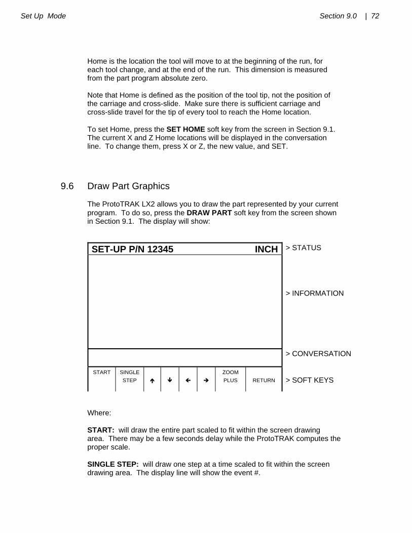
Set Up Mode Section 9.0 | 72
Home is the location the tool will move to at the beginning of the run, for each tool change, and at the end of the run. This dimension is measured from the part program absolute zero. Note that Home is defined as the position of the tool tip, not the position of the carriage and cross-slide. Make sure there is sufficient carriage and cross-slide travel for the tip of every tool to reach the Home location. To set Home, press the SET HOME soft key from the screen in Section 9.1. The current X and Z Home locations will be displayed in the conversation line. To change them, press X or Z, the new value, and SET.
9.6 Draw Part Graphics The ProtoTRAK LX2 allows you to draw the part represented by your current program. To do so, press the DRAW PART soft key from the screen shown in Section 9.1. The display will show:
SET-UP P/N 12345 INCH > STATUS
> INFORMATION
> CONVERSATION
START SINGLE
STEP
ZOOM
PLUS
RETURN
> SOFT KEYS
Where: START: will draw the entire part scaled to fit within the screen drawing area. There may be a few seconds delay while the ProtoTRAK computes the proper scale. SINGLE STEP: will draw one step at a time scaled to fit within the screen drawing area. The display line will show the event #.
73 | Section 9.0 Set Up Mode
: will shift the drawing up by 10% for each press. : will shift the drawing down by 10% for each press : will shift the drawing to the right by 10% for each press : will shift the drawing to the left by 10% for each press ZOOM PLUS: will expand the size of the drawing by 10% for each press. Press the +/- key, and then the ZOOM MINUS key to shrink the drawing. Press and hold the START soft key for 3 seconds to set the scale and shift back to the center of the screen. RETURN: brings the display back to the Set-Up Select screen in Section 9.1
9.7 Tool Path Graphics The ProtoTRAK LX2 allows you to graphically show the tool path associated with your current program. All movements at a programmed feedrate are shown as a solid line. All rapid position paths are shown as broken lines. To show the tool path, press the TOOL PATH soft key from the screen shown in Section 9.1. The display will show the identical screen as the Draw Part Graphics screen (see Section 9.6). The soft keys also operate the same as for Draw Part Graphics. Tool path graphics also checks the validity of your program, so always draw a part once before you run a new program.
9.8 Saving Tool Data Tool types, offsets, radii, and modifiers are not saved with the program (see Section 12 for Program In/Out). To save this data, press the SAVE TOOLS soft key from the screen in Section 9.1.
Set Up Mode Section 9.0 | 74
WARNING If you turn the ProtoTRAK LX2 off (or if you lose power) and you have not saved your tools, all of your tool data will be lost! It is a good habit to do a simple SAVE TOOLS after you have made any tool additions or changes. WARNING For any one tool number, only one set of tool data may exist at any time. When you do a SAVE TOOLS, the data for each tool number will be updated and the previous data (if different) will be lost.
9.9 Service Codes These are special codes which may be entered into the ProtoTRAK LX2 to call up routines used in installation checkout and service.
9.9.1 Metric Default: Code 66 If you wish to have the ProtoTRAK LX2 power up in the metric measurement mode use the following procedure: a. Press the SERV CODES soft key from the screen in Section 9.1. b. Press 66 SET when the conversation line prompts "CODE".
9.9.2 English Default: Code 67 If you wish to have the ProtoTRAK LX2 power up in the English measurement mode use the following procedure: a. Press the SERV CODES soft key from the screen in Section 9.1. b. Press 67 SET when the conversation line prompts "CODE".
9.9.3 Preset All Defaults: Code 126 If you wish to have all service defaults reset to those standardized at the factory use the following procedure: a. Press the SERV CODES soft key from the screen in Section 9.1. b. Press 126 SET when the conversation line prompts "CODE".
75 | Section 9.0 Set Up Mode
9.9.4 Software ID: Code 33 If you wish to check the revision of the software in your ProtoTRAK LX2 use the following procedure: a. Press the SERV CODES soft key from the screen in Section 9.1. b. Press 33 SET when the conversation line prompts "CODE". The software identification will be shown in the Information area of the screen. 9.9.5 Initialize Entire Tool Table: Code 139 If you wish to erase the entire tool table including offsets, radii and modifiers, use the following procedure: a. Press the SERV CODES soft key from the screen in Section 9.1. b. Press 139 SET when the conversation line prompts “CODE.” The tool table will automatically be completely erased and lost.
_________________________________________________________________ Southwestern Industries, Inc.
TRAK TRL & ProtoTRAK LX2 Programming, Operating & Care Manual
SECTION
____________ 10.0 ___________________________ Program Run Mode

Program Run Mode Section 10.0 | 77
10.0 PROGRAM RUN MODE In the Run Mode the ProtoTRAK LX2 drives the carriage and cross-slide, and provides you with all the instructions necessary to successfully run the part.
10.1 Enter Run Mode Press MODE and select the RUN soft key. The display will show:
RUN P/N 12345 INCH
> STATUS
> INFORMATION
SELECT > CONVERSATION
START
START
EVENT #
> SOFT KEYS
10.2 Starting to Run Before running a part, you need to establish the position relationship between the part and tool. That is, you need to be certain that when the readout displays X=0 ABS and Z=0 ABS for any input tool, then that tool is at the program absolute zero of the part. To do this: a. Enter the DRO Mode. b. Load a tool and call up its Tool #. c. Load a part. d. Move to a known position on the part.
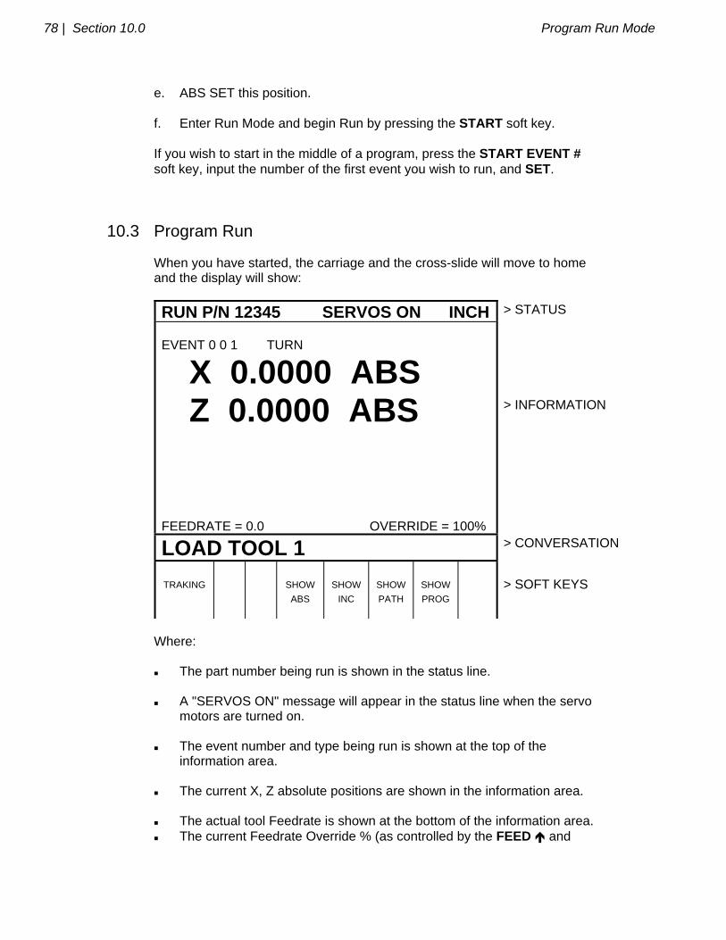
78 | Section 10.0 Program Run Mode
e. ABS SET this position. f. Enter Run Mode and begin Run by pressing the START soft key. If you wish to start in the middle of a program, press the START EVENT # soft key, input the number of the first event you wish to run, and SET.
10.3 Program Run When you have started, the carriage and the cross-slide will move to home and the display will show:
RUN P/N 12345 SERVOS ON INCH > STATUS
EVENT 0 0 1 TURN
X 0.0000 ABS Z 0.0000 ABS FEEDRATE = 0.0 OVERRIDE = 100%
> INFORMATION
LOAD TOOL 1 > CONVERSATION
TRAKING
SHOW
ABS
SHOW
INC
SHOW
PATH
SHOW
PROG
> SOFT KEYS
Where: The part number being run is shown in the status line. A "SERVOS ON" message will appear in the status line when the servo motors are turned on. The event number and type being run is shown at the top of the information area. The current X, Z absolute positions are shown in the information area. The actual tool Feedrate is shown at the bottom of the information area. The current Feedrate Override % (as controlled by the FEED and
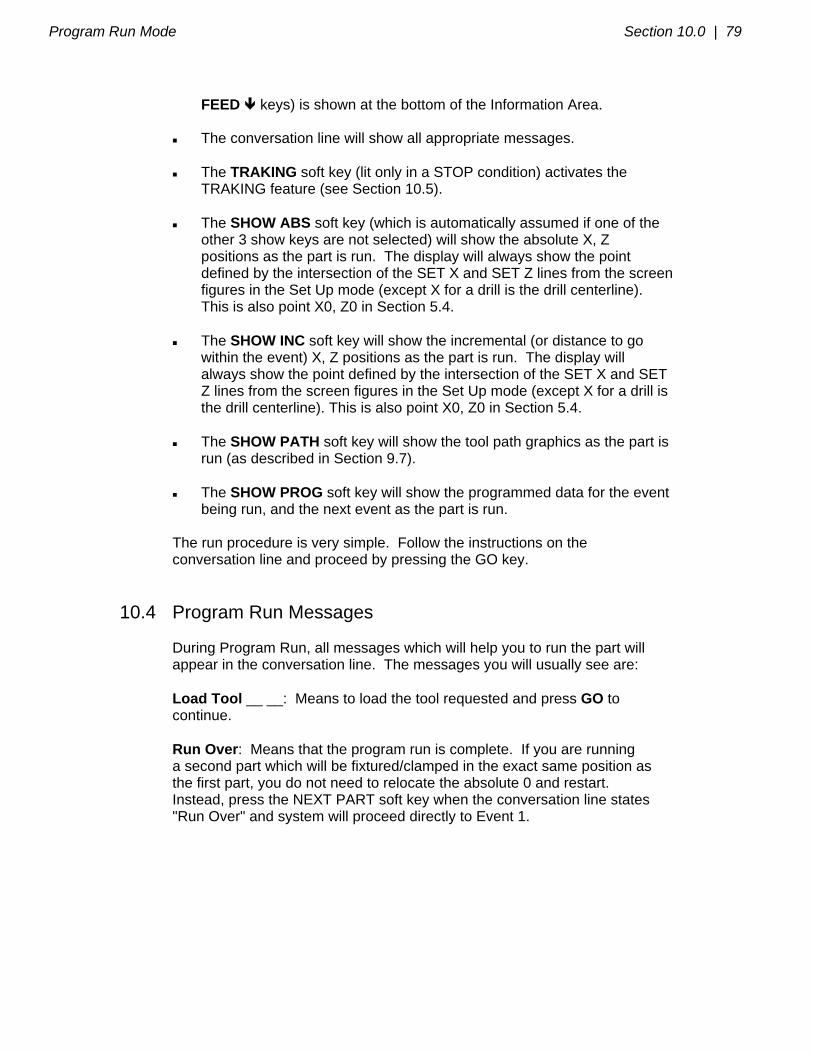
Program Run Mode Section 10.0 | 79
FEED keys) is shown at the bottom of the Information Area. The conversation line will show all appropriate messages. The TRAKING soft key (lit only in a STOP condition) activates the TRAKING feature (see Section 10.5). The SHOW ABS soft key (which is automatically assumed if one of the other 3 show keys are not selected) will show the absolute X, Z positions as the part is run. The display will always show the point defined by the intersection of the SET X and SET Z lines from the screen figures in the Set Up mode (except X for a drill is the drill centerline). This is also point X0, Z0 in Section 5.4. The SHOW INC soft key will show the incremental (or distance to go within the event) X, Z positions as the part is run. The display will always show the point defined by the intersection of the SET X and SET Z lines from the screen figures in the Set Up mode (except X for a drill is the drill centerline). This is also point X0, Z0 in Section 5.4. The SHOW PATH soft key will show the tool path graphics as the part is run (as described in Section 9.7). The SHOW PROG soft key will show the programmed data for the event being run, and the next event as the part is run. The run procedure is very simple. Follow the instructions on the conversation line and proceed by pressing the GO key.
10.4 Program Run Messages During Program Run, all messages which will help you to run the part will appear in the conversation line. The messages you will usually see are: Load Tool __ __: Means to load the tool requested and press GO to continue. Run Over: Means that the program run is complete. If you are running a second part which will be fixtured/clamped in the exact same position as the first part, you do not need to relocate the absolute 0 and restart. Instead, press the NEXT PART soft key when the conversation line states "Run Over" and system will proceed directly to Event 1.
80 | Section 10.0 Program Run Mode
10.5 TRAKING The TRAKING feature allows you to progress through the program run using either the X or Z handwheel to control both axes of motion. The TRAKING soft key will be lit whenever the program run is in a STOP condition. Press the TRAKING soft key to activate this feature and use as follows: a. Rotate the Z handwheel counterclockwise (motion into the part) to move the carriage AND cross-slide through the programmed path. b. Or, rotate the X handwheel clockwise (motion into the part) to move the carriage AND cross-slide through the programmed path. c. The F/C, fine/coarse resolution selection is activated. d. The faster you move the handwheel, the faster you will move the tool. e. If you stop turning the handwheel, the tool will stop. f. If you reverse the handwheel, you will move backwards through the program for up to three line segments. g. You may use the jog stick to jog away from your programmed position (handy for clearing a stringy chip or making a measurement). Turning the handwheel will bring you back to the programmed position you left in a straight line. h. To resume CNC run, press STOP. The TRAKING and CNC RUN soft keys will light. Press the CNC RUN soft key and the GO key to resume CNC run. Or press TRAKING to resume Traking.
10.6 Stop At any time, the program may be halted by pressing the STOP key. This freezes the program at that point. To continue, press the GO key or TRAKING soft key.
10.7 Feedrate Override The run feedrate may be changed at any time by pressing the FEED or FEED keys. Each press increases or reduces the programmed feedrate, as well as rapid by 10%.
Program Run Mode Section 10.0 | 81
10.8 Threading Exceptions If your program contains a thread event and you are using the TRAKing feature, the CNC run automatically takes over for the actual threading pass. The run reverts to TRAKing to reposition for the next pass or for the next event. If you cut a thread and then wish to adjust the XMOD for a more precise thread, you may re-run the event without cross-threading the part. However, you may NOT change RPM from the first run to the next.
10.9 Data Errors The Program Mode in Section 7 describes several rules which must be followed to successfully program a part. In addition, a program must make sense geometrically. Data errors will nearly always be detected when the ProtoTRAK LX2 runs through a program--either as a Trial Run or on an actual part run. They may also be detected in the Set Up mode when using the Draw Part or Tool Path Graphics routines. Whenever the ProtoTRAK LX2 detects a data error the display will change to a screen typified by the example below.
> STATUS
EXPLANATION The programmed arc or circle is a point.
XZ begin, end, center are the same.
SOLUTION Check all XZ dimensions.
> INFORMATION
Data Error 5013 around event 21 > CONVERSATION
RETURN
> SOFT KEYS
The Conversation Line displays the error number (not necessarily important to you) and the event where the error was detected. This is not necessarily the event which is in error since the system often "looks ahead" to make sure there is compatibility from one event to another.

82 | Section 10.0 Program Run Mode
In addition, an explanation is given for each data error type as well as a suggested solution. Press the RETURN soft key to go back to the Select Mode screen, correct your error, and proceed.
10.10 Fault Messages The ProtoTRAK performs a number of automatic checks or self-diagnostics on itself. If problems are found it will signal you through the display. The conversation line will display "Fault __ __ __ __". The information area will display an explanation and suggested solution. Press the RETURN key to get back to the Select Mode screen.
Math Help Mode Section 11.0 | 83
_________________________________________________________________ Southwestern Industries, Inc.
TRAK TRL & ProtoTRAK LX2 Programming, Operating & Care Manual
SECTION
____________ 11.0 ___________________________
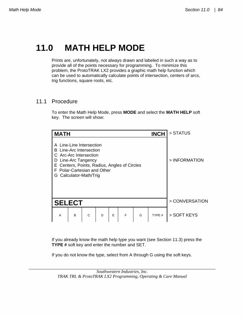
Math Help Mode Section 11.0 | 84
_________________________________________________________________ Southwestern Industries, Inc.
TRAK TRL & ProtoTRAK LX2 Programming, Operating & Care Manual
11.0 MATH HELP MODE Prints are, unfortunately, not always drawn and labeled in such a way as to provide all of the points necessary for programming. To minimize this problem, the ProtoTRAK LX2 provides a graphic math help function which can be used to automatically calculate points of intersection, centers of arcs, trig functions, square roots, etc.
11.1 Procedure To enter the Math Help Mode, press MODE and select the MATH HELP soft key. The screen will show:
MATH INCH > STATUS
A Line-Line Intersection B Line-Arc Intersection C Arc-Arc Intersection D Line-Arc Tangency E Centers, Points, Radius, Angles of Circles F Polar-Cartesian and Other G Calculator-Math/Trig
> INFORMATION
SELECT > CONVERSATION
A
B
C
D
E
F
G
TYPE #
> SOFT KEYS
If you already know the math help type you want (see Section 11.3) press the TYPE # soft key and enter the number and SET. If you do not know the type, select from A through G using the soft keys.

85 | Section 11.0 Math Help Mode
NOTE: For selections A-F, all X dimensions should be input and read as diameters, not radii. If, for example, you wish to find the intersection of a straight line and an arc or circle, press the B soft key. The screen will show:
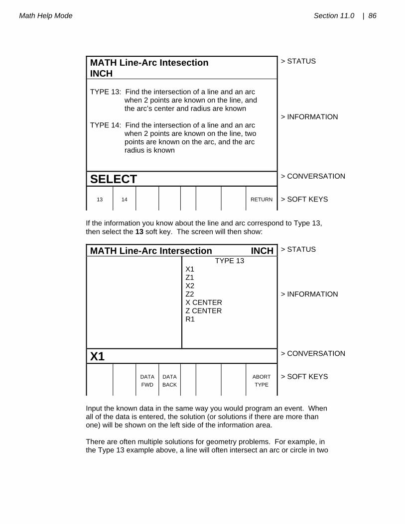
Math Help Mode Section 11.0 | 86
MATH Line-Arc Intesection INCH
> STATUS
TYPE 13: Find the intersection of a line and an arc when 2 points are known on the line, and the arc’s center and radius are known TYPE 14: Find the intersection of a line and an arc when 2 points are known on the line, two points are known on the arc, and the arc radius is known
> INFORMATION
SELECT > CONVERSATION
13
14
RETURN
> SOFT KEYS
If the information you know about the line and arc correspond to Type 13, then select the 13 soft key. The screen will then show:
MATH Line-Arc Intersection INCH > STATUS
TYPE 13 X1 Z1 X2 Z2 X CENTER Z CENTER R1
> INFORMATION
X1 > CONVERSATION
DATA
FWD
DATA
BACK
ABORT
TYPE
> SOFT KEYS
Input the known data in the same way you would program an event. When all of the data is entered, the solution (or solutions if there are more than one) will be shown on the left side of the information area. There are often multiple solutions for geometry problems. For example, in the Type 13 example above, a line will often intersect an arc or circle in two
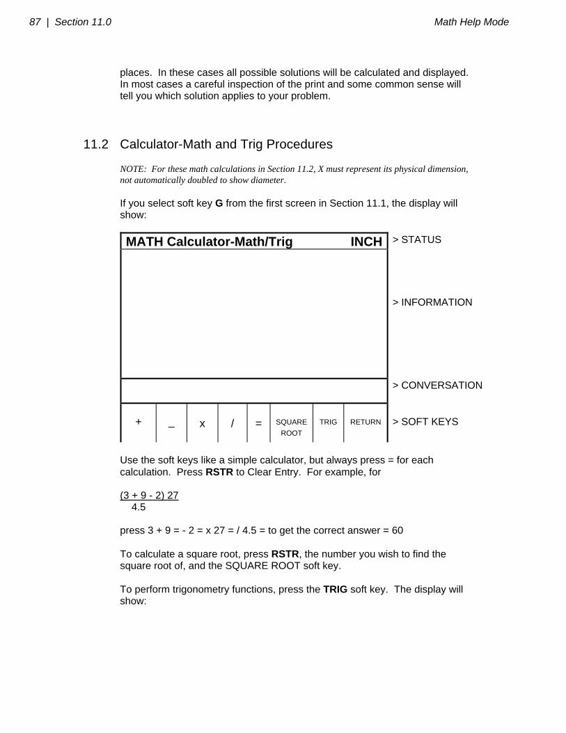
87 | Section 11.0 Math Help Mode
places. In these cases all possible solutions will be calculated and displayed. In most cases a careful inspection of the print and some common sense will tell you which solution applies to your problem.
11.2 Calculator-Math and Trig Procedures NOTE: For these math calculations in Section 11.2, X must represent its physical dimension, not automatically doubled to show diameter. If you select soft key G from the first screen in Section 11.1, the display will show:
MATH Calculator-Math/Trig INCH > STATUS
> INFORMATION
> CONVERSATION
+
_
x
/
=
SQUARE
ROOT
TRIG
RETURN
> SOFT KEYS
Use the soft keys like a simple calculator, but always press = for each calculation. Press RSTR to Clear Entry. For example, for (3 + 9 - 2) 27 4.5 press 3 + 9 = - 2 = x 27 = / 4.5 = to get the correct answer = 60 To calculate a square root, press RSTR, the number you wish to find the square root of, and the SQUARE ROOT soft key. To perform trigonometry functions, press the TRIG soft key. The display will show:

Math Help Mode Section 11.0 | 88
MATH Calculator-Math/Trig INCH > STATUS
> INFORMATION
> CONVERSATION
SINE
COS
TAN
ARC
SINE
ARC
COS
ARC
TAN
TRI-
ANGLE
RETURN
> SOFT KEYS
To calculate the sine, cosine or tangent of an angle, input the angle in degrees and press the SINE, COS or TAN soft key. To calculate the arcsine, arccosine, or arctangent of a number, input the number and press the ARC SINE, ARC COS or ARC TAN soft key to compute the angle in degrees. Press TRIANGLE to find unknown angles or side lengths of a (90 degree) right triangle. The left side of the screen shows a right triangle with sides A, B, C and angles G and H. Simply input the data you know, and when the ProtoTRAK knows enough it will automatically show the rest.
11.3 Math Help Types NOTE: X should always be given and read in diameter, not radius.
A. Line-Line Intersection Type 10 : Find the intersection of 2 lines when any 2 points are known on each line. Type 11: Find the intersection of 2 lines when 2 points are known on one line, one point is known on the other line, and the angle between the lines is known. Type 12: Find the intersection of 2 lines when 2 points are known on one, one point is known on the other, a radius tangent to both lines is

89 | Section 11.0 Math Help Mode
known, and when one of the points on the two known point lines is also on the radius.
B. Line-Arc Intersection Type 13: Find the intersection of a line and an arc when 2 points are known on the line and the arc's center and radius are known. Type 14: Find the intersection of a line and an arc when 2 points are known on the line, 2 points are known on the arc, and the radius is known.
C. Arc-Arc Intersection Type 15: Find the intersection of 2 arcs when the center and radius of each are known.
D. Line-Arc Tangency Type 16: Find the intersection of a line tangent to 2 arcs when the centers and radii of each are known. Type 17: Find the intersection of a line tangent to an arc when one point is known on the line and the arc's center and radius are known. Type 18: Find the intersection of a line tangent to 2 arcs when the centers and radii of each are known. Line crosses centers. Type 19: Find the intersection of an arc tangent to 2 other arcs when the centers and radii of the 2 are known, and the radius of the first is known.
E. Centers, Points, Radius and Angles of Circles Type 20: Calculate the center of an arc when 2 points on the arc and its radius are known. Type 21: Calculate a point on an arc when the center, another point on the arc, and the angle between the arc points are known. Type 22: Calculate the radius of an arc or circle when one point on the arc and the center are known. Type 23: Calculate the center of an arc or circle when 2 points on the arc

Math Help Mode Section 11.0 | 90
and the angle between them are known. Type 24: Calculate the center and radius of an arc or circle when 3 different points on the arc or circle are known.
F. Polar-Cartesian, Other Type 25: Calculate the cartesian (X and Z) location when the polar (R and angle) coordinates are known. Type 26: Calculate the decimal angle from an angle given in degrees, minutes, and seconds.
_________________________________________________________________ Southwestern Industries, Inc.
TRAK TRL & ProtoTRAK LX2 Programming, Operating & Care Manual
SECTION
____________ 12.0 ___________________________ Program In/Out Mode

Program In/Out Mode Section 12.0 | 95
12.0 PROGRAM IN/OUT MODE You may store and retrieve programs in two different ways: 1. The ProtoTRAK LX2 has two built-in floppy disk drives. One holds the system's operating software and is not accessible. The other is accessible through a door in the computer cabinet and can store 192 moderate size programs. 2. You may store and retrieve programs through an RS232 link to most computers. The RS232 port is located on the back of the pendant box. This same link is used to load programs which have been written via a CAD/CAM system. All programs are transmitted through the ProtoTRAK LX2's current or computer program memory. Programs are sent from the computer memory (that is, a current program) to one of the above two permanent memory locations. Or programs are retrieved from one of the two, and loaded into the ProtoTRAK LX2's computer memory. Programs may not be sent directly from one of the above two storage devices to another.
12.1 Cautions About Storing and Retrieving Programs Care must be taken to keep from losing a program you wish to keep. This can happen two ways. First, whenever a program is retrieved, it is loaded into the ProtoTRAK LX2's computer program memory. When this happens, your existing current program is erased. Therefore, if your current program is one you want to keep, be certain to store it before you retrieve another program. Second, to store a program it must have a part number so that the ProtoTRAK LX2 can find it if you want it retrieved. However, no two programs can have the same part number (how would the system decide which to retrieve?). Therefore, if you store a program with any particular part number, it will automatically erase any other program with that same part number.
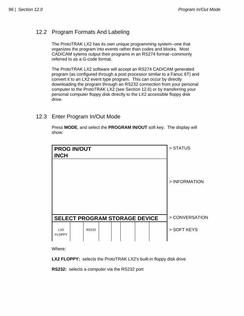
96 | Section 12.0 Program In/Out Mode
12.2 Program Formats And Labeling The ProtoTRAK LX2 has its own unique programming system--one that organizes the program into events rather than codes and blocks. Most CAD/CAM sytems output their programs in an RS274 format--commonly referred to as a G-code format. The ProtoTRAK LX2 software will accept an RS274 CAD/CAM generated program (as configured through a post processor similar to a Fanuc 6T) and convert it to an LX2 event type program. This can occur by directly downloading the program through an RS232 connection from your personal computer to the ProtoTRAK LX2 (see Section 12.6) or by transferring your personal computer floppy disk directly to the LX2 accessible floppy disk drive.
12.3 Enter Program In/Out Mode Press MODE, and select the PROGRAM IN/OUT soft key. The display will show:
PROG IN/OUT INCH
> STATUS
> INFORMATION
SELECT PROGRAM STORAGE DEVICE > CONVERSATION
LX2
FLOPPY
RS232
> SOFT KEYS
Where: LX2 FLOPPY: selects the ProtoTRAK LX2's built-in floppy disk drive RS232: selects a computer via the RS232 port
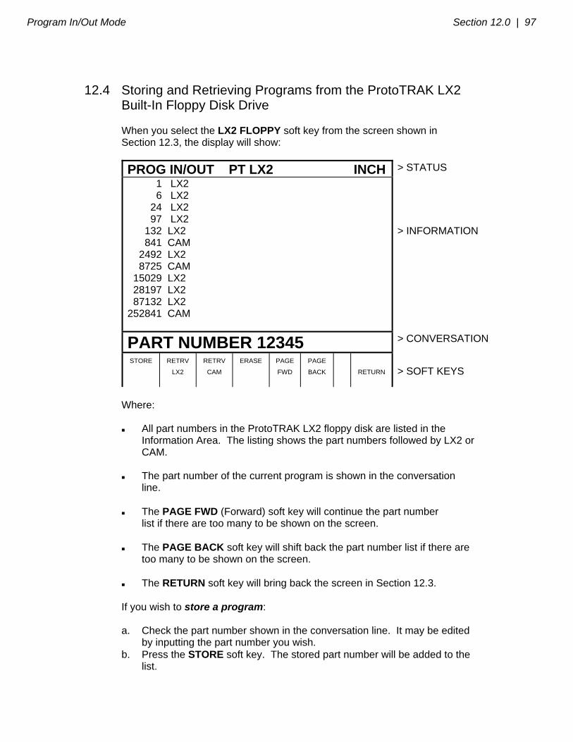
Program In/Out Mode Section 12.0 | 97
12.4 Storing and Retrieving Programs from the ProtoTRAK LX2 Built-In Floppy Disk Drive When you select the LX2 FLOPPY soft key from the screen shown in Section 12.3, the display will show:
PROG IN/OUT PT LX2 INCH > STATUS
1 LX2 6 LX2 24 LX2 97 LX2 132 LX2 841 CAM 2492 LX2 8725 CAM 15029 LX2 28197 LX2 87132 LX2 252841 CAM
> INFORMATION
PART NUMBER 12345 > CONVERSATION
STORE RETRV
LX2
RETRV
CAM
ERASE PAGE
FWD
PAGE
BACK
RETURN
> SOFT KEYS
Where: All part numbers in the ProtoTRAK LX2 floppy disk are listed in the Information Area. The listing shows the part numbers followed by LX2 or CAM. The part number of the current program is shown in the conversation line. The PAGE FWD (Forward) soft key will continue the part number list if there are too many to be shown on the screen. The PAGE BACK soft key will shift back the part number list if there are too many to be shown on the screen. The RETURN soft key will bring back the screen in Section 12.3. If you wish to store a program: a. Check the part number shown in the conversation line. It may be edited by inputting the part number you wish. b. Press the STORE soft key. The stored part number will be added to the list.
98 | Section 12.0 Program In/Out Mode
If you wish to retrieve a program: a. Input the part number so it is shown in the conversation line. Be certain it is a part number in the list. b. Press the RETRV LX2 soft key if the part is labeled as one generated by the LX2. This program will now be your current program. c. Press the RETRV CAM soft key if the part is labeled as one generated with a CAM (see Section 12.6). This program will now be your current program. If you wish to erase a program from the list: a. Input the part number so it is shown in the conversation line. Be certain it is a part number in the list. b. Press the ERASE soft key. The program will be permanently erased from the floppy disk and the part number will be eliminated from the list.
12.5 Backing Up Your LX2 Programs It is strongly recommended that important programs not be solely stored on the LX2 accessible floppy disk drive. A back-up may be made in two ways: a. Remove the LX2 accessible floppy diskette which holds the part programs and, using an IBM compatible computer, make a copy or store the data on its hard drive. b. Use the RS232 link (see Section 12.6) to transfer programs to your computer for storage. If at any time you feel the program data on the LX2 floppy diskette is lost or damaged, use your back-up to reproduce the programs.
12.6 Storing and Retrieving Programs through the RS232 Port - Including CAD/CAM Generated Programs If you wish to use the RS232 port to communicate between your ProtoTRAK LX2 and your computer, call the Customer Service Group at Southwestern Industries and let us know what computer you wish to interface to. The telephone number is 310/608-4422. You will be sent the necessary equipment and installation instructions at no cost. Please be certain the installation is correct before attempting to use
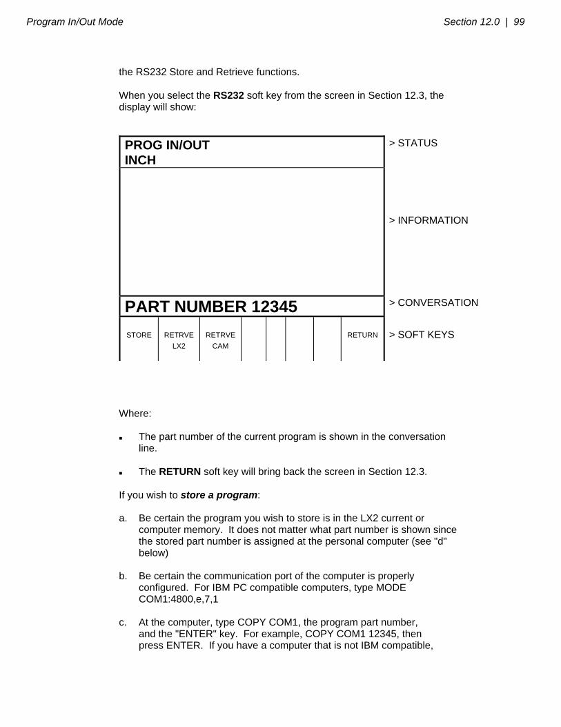
Program In/Out Mode Section 12.0 | 99
the RS232 Store and Retrieve functions. When you select the RS232 soft key from the screen in Section 12.3, the display will show:
PROG IN/OUT INCH
> STATUS
> INFORMATION
PART NUMBER 12345 > CONVERSATION
STORE
RETRVE
LX2
RETRVE
CAM
RETURN
> SOFT KEYS
Where: The part number of the current program is shown in the conversation line. The RETURN soft key will bring back the screen in Section 12.3. If you wish to store a program: a. Be certain the program you wish to store is in the LX2 current or computer memory. It does not matter what part number is shown since the stored part number is assigned at the personal computer (see "d" below) b. Be certain the communication port of the computer is properly configured. For IBM PC compatible computers, type MODE COM1:4800,e,7,1 c. At the computer, type COPY COM1, the program part number, and the "ENTER" key. For example, COPY COM1 12345, then press ENTER. If you have a computer that is not IBM compatible,

100 | Section 12.0 Program In/Out Mode
use the standard send message. d. At the ProtoTRAK LX2 press the STORE soft key. The program will be sent, and the conversation line will read "STORING." When complete, the screen will revert to the one shown in Section 12.3. If you wish to retrieve a program that has been stored or written by a CAD/CAM system: a. Input the part number you wish the program to be assigned in the LX2. b. Press the RETRVE LX2 soft key if the program you wish to retrieve is in the LX2 event type format. Press the RETRVE CAM soft key if the program you wish to retrieve is in the CAD/CAM, RS274, G-code format. c. Be certain the communication port at the computer is properly configured. For IBM PC compatible computers, type MODE COM1:4800,e,7,1 Note: If you write a program using a CAD/CAM system on your computer and intend to enter it into the ProtoTRAK LX2 via the RS232 port, you must name the program with one to eight numerical digits followed by a decimal point, followed by CAM (for example, 123.CAM or 87654321.CAM). If these rules are not followed the LX2 will not recognize the program. d. At the computer, type COPY, the program part number, COM1 and the ENTER key. For example, COPY 12345.LX2 COM1, then press ENTER. If you have a computer that is not IBM compatible, use the standard send procedure. e. When the program has been completely received by the LX2, the screen will revert to the one shown in Section 12.3. Note: Do not attempt to write LX2 formatted programs through your CAD/CAM programming system.

Program In/Out Mode Section 12.0 | 101
Southwestern Industries, Inc
TRAK Warranty Policy
Warranty TRAK products are warranted to the original purchaser to be free from defects in work-manship and materials for the following periods:
Product Warranty Period Materials Factory Labor New TRAK/ProtoTRAK
1 Year 1 Year
Any EXCHANGE Unit 90 Days 90 Days The warranty period starts on the date of the invoice to the original purchaser from Southwestern Industries, Inc. (SWI) or their authorized distributor. If a product, subsystem or component under warranty fails, it will be repaired or exchanged at our option for a properly functioning unit in similar or better condition. Such repairs or exchanges will be made FOB Factory/Los Angeles or the location of our nearest factory representative or authorized distributor. Disclaimers of Warranties
This warranty is expressly in lieu of any other warranties, express or implied, including any implied warranty of merchantability or fitness for a particular purpose, and of any other obligations or liability on the part of SWI (or any producing entity, if different).
Warranty repairs/exchanges do not cover incidental costs such as installation, labor,
freight, etc.
SWI is not responsible for consequential damages from use or misuse of any of its products.
TRAK products are precision mechanical/electromechanical/electronic systems and
must be given the reasonable care that these types of products require.
Accidental damage, beyond the control of SWI, is not covered by the warranty. Thus, the warranty does not apply if a product has been abused, dropped, hit or disassembled.
Improper installation by or at the direction of the customer in such a way that the
product consequently fails, is considered to be beyond the control of the manufacturer and outside the scope of the warranty.
Rev 020713