prototype carbon fund - globalclearinghouse.org10/documents/peru... · pallasca motil chauall...
TRANSCRIPT

PROJECT DESIGN DOCUMENT FORM (CDM PDD) - Version 02 CDM – Executive Board page 1
This template shall not be altered. It shall be completed without modifying/adding headings or logo, format or font.
Project Design Document
For
Poechos I
November 2004
Prototype Carbon Fund
Prepared by
World Bank Carbon Finance Business

PROJECT DESIGN DOCUMENT FORM (CDM PDD) - Version 02 CDM – Executive Board page 2
This template shall not be altered. It shall be completed without modifying/adding headings or logo, format or font.
ABBREVIATIONS
APRF Annual Plant Fuel Requirement (TJ) Baseline emissions Product of the EFy times EGy BLS Latest Baseline Study (2004) BM Build Margin Emission Factor BM2 Build Margin Emission Factor – Option 2 C Carbon Content (tC/TJ) Factor - 1996 IPCC worldwide values CDM Clean Development Mechanism CERs Certified Emission Reductions
CM Combined Margin Emission Factor COEF tCO2/MWh COES Committee of Economical Operation of the SEIN (Dispatch Center) DOE Designated Operational Entity DDA-OM Dispatch Data Analysis Operating Margin Emission Factor ECL Peru’s Electric Concessions Law of 1993 (Law 25844) EFy Baseline Emission Factor (tCO2/MWh) EGy The Project annual generation (MWh) ENOSA Electronoroeste S.A (The Project Final Client) ERs Green House Gases Emissions Reductions GHG Green House Gases GWh Gigawatts hours HP Hydropower plant (s) HT Heat Turbine LRMC Long Run Marginal Cost of the SEIN Merit Order Grid Dispatch Weekly Merit Order MINEM Peru’s Department of Energy and Mines Monthly Merit Order Average of Four Weekly Grid Dispatch Merit Orders MP Monitoring Plan MWh Megawatts hours NEC Net Efficiency Conversion O Oxidation Factor - 1996 IPCC worldwide values OM Operating Margin Emission Factor OSINERG Peru’s Energy Investment Supervisory Agency (Regulatory Entity) PPA Power Purchase Agreement PCF Prototype Carbon Fund SEIN National Electric Grid or National Interconnected Electric Grid SINERSA Sindicato Energetico S.A (The Project Developer and The Project Current Operator) tCO2e Tons of carbon dioxide equivalent The Operator SINERSA (The Project Operator) TP Thermal fossil fuel-fired plant(s)

PROJECT DESIGN DOCUMENT FORM (CDM PDD) - Version 02 CDM – Executive Board page 3
This template shall not be altered. It shall be completed without modifying/adding headings or logo, format or font.
CLEAN DEVELOPMENT MECHANISM
PROJECT DESIGN DOCUMENT FORM (CDM-PDD) Version 02 - in effect as of: 1 July 2004)
CONTENTS A. General description of project activity B. Application of a baseline methodology C. Duration of the project activity / Crediting period D. Application of a monitoring methodology and plan E. Estimation of GHG emissions by sources F. Environmental impacts G. Stakeholders’ comments
Annexes Annex 1: Contact information on participants in the project activity Annex 2: Information regarding public funding Annex 3: Baseline information
Annex 4: Monitoring plan

PROJECT DESIGN DOCUMENT FORM (CDM PDD) - Version 02 CDM – Executive Board page 4
This template shall not be altered. It shall be completed without modifying/adding headings or logo, format or font.
SECTION A. General description of project activity A.1 Title of the project activity: Poechos I (“The Project”) A.2. Description of the project activity: The Project is a hydroelectric power plant located in Peru, in the North-western Department of Piura. The Project’s installed capacity and projected yearly average generation is 15.4 MW and 58,500 MWh per year, respectively. The expected load factor is 43.36%. The Project is expected to displace 31,878 tCO2 per year, which accounts for 223,146 tCO2e for the first crediting period (7 years), generating the equivalent amount of Certified Emission Reductions (CERs). Methane and Carbon Dioxide are negligible. Therefore, there is no need to monitor leakage and it will not be taken into account when calculating ERs. The Project takes advantage of the existing Poechos reservoir of 48 m height and approximately 1,000 m length (with a water discharge of 45 m³/s), constructed between 1971 and 1974, exclusively for the irrigation system named Chira-Piura1. The machine house was built downstream at the bottom gate of the dam. The Project uses a portion of the discharged water from the Poechos Dam, affecting the flow of the Chira River and the Miguel Checa Canal. The water concession granted to the sponsors by the Peruvian Department of Agriculture was based upon the use of the flow required for agriculture – so that generation received lower priority than agricultural needs. Although the reservoir allows for a multi-year regulation of the water, The Project will not have facilities to regulate its energy production because the control of the discharges is managed by the Agricultural Authority of the region. The spatial extent of The Project boundary is the National Electric Grid (SEIN). The Project is connected to the SEIN through the Sullana Substation - which belongs to Electronoroeste S.A. (ENOSA). The expected 58.5 GWh of electricity generated per year will be sold to ENOSA (stated-owned enterprise) – a PPA is currently signed between The Project Operator and Sponsor (SINERSA) and ENOSA. The Project will have an expected minimum plant operating life of 40 years. A.3. Project participants: SINERSA Is a Peruvian private company solely developer, operator and shareholder of The Project. It holds the definitive concession right to build and to operate the hydropower plant of Poechos I (The Project) acquired from The Peruvian Department of Energy and Mines. The World Bank Carbon Finance Business The World Bank has pioneered the market for greenhouse gas emission reductions through its Carbon Finance Business (CFB). The CFB leverages public and private investment into projects that generate ERs. Through the CFB the World Bank is working to ensure that developing and transition economies get a sizable share of the growing carbon market under the Kyoto Protocol’s Clean Development Mechanism (CDM) and Joint Implementation (JI); with client countries providing high-quality carbon emission reductions in exchange for development dollars, technological know-how, and clean technologies for sustainable development. CFB products include: The Prototype Carbon Fund (PCF), The Netherlands
1 The Chira-Piura dam is the largest in Peru.

PROJECT DESIGN DOCUMENT FORM (CDM PDD) - Version 02 CDM – Executive Board page 5
This template shall not be altered. It shall be completed without modifying/adding headings or logo, format or font.
Clean Development Mechanism Facility, The Community Development Carbon Fund (CDCF), The BioCarbon Fund, The Italian Carbon Fund, and The World Bank Staff Climate Protection Program. The Prototype Carbon Fund The Prototype Carbon Fund (PCF) is the World Bank’s first carbon fund. The PCF was created as a response to the need to understand and test the procedures for creating a market in project-based emission reductions under the Kyoto Protocol's flexible mechanisms. The PCF has played a pioneering role in developing the market for greenhouse gas emission reductions, while promoting sustainable development, and offering a learning-by-doing opportunity to its stakeholders; it has paved the way for the additional carbon funds established by the World Bank. Operational since April 2000, the Prototype Carbon Fund functions as an innovative public/private partnership – as of today, the partnership is between 17 companies and 6 governments - aimed at mitigating climate change. The PCF’s mission is to pioneer the market for project-based greenhouse gases ERs. The PCF pilots production of ERs within the framework of the JI and the CDM. The PCF invests contributions made by companies and governments in projects designed to produce ERs fully consistent with the Kyoto Protocol and the emerging framework for JI and the CDM. Contributors, or "Participants" in the PCF, receive a pro rata share of the ERs, verified and certified in accordance with agreements reached with the respective countries "hosting" the projects. The Government of the Netherlands The Dutch government is one of the six governments “participants” in the PCF. As of today, it is the second largest buyer of ERs (26% total volume of ERs purchased), just after Japanese entities (41%). The Dutch government decided to use the JI and CDM instruments to reach 50% of its Kyoto target of 6% in the periods from 1990 to 2008 and 2012. This target equals 100 million tons of carbon dioxide equivalent. The Dutch government implements projects by means of the Dutch Joint Implementation ERUPT tenders and the CDM Purchase Program. The Netherlands Clean Development Mechanism Facility In May 2002, the World Bank agreed to purchase greenhouse gases ERs on behalf of The Government of The Netherlands. This facility purchases ERs from projects in developing countries under the CDM, established by the Kyoto Protocol to the UN Framework Convention on Climate Change. This Facility’s initial target was to purchase 16 million tons of carbon dioxide equivalent (mtCO2e) of emissions reductions in the first two years of the agreement. The agreement has now been extended, with a firm commitment to purchase an additional 5 mtCO2e by mid-2005. The agreement also allows for a further purchase of up to approximately 11 million tons of carbon dioxide equivalent. A.4. Technical description of the project activity: A.4.1. Location of the project activity: Department of Piura, Peru A.4.1.1. Host Party(ies): Republic of Peru A.4.1.2. Region/State/Province etc.: Department of Piura (Piura Region) / Sullana Province / Lancones District.

PROJECT DESIGN DOCUMENT FORM (CDM PDD) - Version 02 CDM – Executive Board page 6
This template shall not be altered. It shall be completed without modifying/adding headings or logo, format or font.
A.4.1.3. City/Town/Community etc: Lancones Town (capital of the Lancones District) A.4.1.4. Detail of physical location, including information allowing the unique identification of this project activity (maximum one page): The Project is located in the North-western Peruvian Department of Piura, in the Sullana Province, in the Lancones District, in the Lancones Town. The Project site is 40 Km from the Sullana district (capital of the Sullana Province), and 30 km from the Peruvian-Ecuadorian border. The plant is located within the property of the Poechos dam, built over the Chira River2
The Project Site Map
Source: SINERSA
2 In 1974, with the solely purpose to provide irrigation for 110,000 has. in the Chira and Piura valleys.

PROJECT DESIGN DOCUMENT FORM (CDM PDD) - Version 02 CDM – Executive Board page 7
This template shall not be altered. It shall be completed without modifying/adding headings or logo, format or font.
MALPASO
ICAVILLACURI
NASCA
OROYA NUEVATARMA
CONDORCOCHA
HUARAZ
BAGUA GRANDE
MOYOBAMBA
PIURA OESTE
OcéanoPacífico
Ecuador
Colombia
Brasil
Boliv
ia
Chile
SISTEMA ELÉCTRICO INTERCONECTADO NACIONAL
ABANCAYANDAHUAYLAS
QUILLABAMBA
MACHU PICCHUAYACUCHOINGENIOCAUDALOSA
CAÑETE
TAM BO DE MORA
PISCOPARACAS
SANTA MARGARITA
PALPA PUQUIO
MARCONASAN NICOLAS
INDEPENDENCIA
RESTITUCION
JAUJA
CHUMPE
LA OROYAHUARAL
HUACHO
ANDAHUASI
SAN JUAN
HUINCO
CALLAHUANCAMOYOPAMPAHUAMPANIBALNEARIOS
SANTA ROSAVENTANILLA
CHAVARRIAZAPALLAL
CAHUA
UCHUCCHACUA
HUARMEY
CHIMBOTE
CASMA
SAN JACINTO
NEPEÑA
SIHUASLA PAMPA
CAÑON DEL PATOCARAZ AUCAYACU
YARINACOCHA
RIOJA
PUCALLPA
TINGO MARIA
HUANUCO
PALLASCA
MOTILCHAUALL
TRUJILLO NORTETRUJILLO NORTE
TUMBESZORRITOS
MALACASTALARA
El ARENAL
PAITA
SULLANA
VERDUN
CURUMUY
CHULUCANAS
MUYO
IQUITOS
REPARTICION
BAGUA CHICA
TARAPOTO
JAENLA PELOTA
ZARUMILLA
PACASMAYO
CARHUAQUERO
CHICLAYOOESTE
CAJAMARCACHILETEGALLITO CIEGOGUADALUPE
MOTUPE
LA VIÑAILLIMO
VIRU
CARHUAZ
TICAPAMPAVIZCARRA
PARAMONGA
POMACOCHA
PARAGSHA II
GOYLLARISQUIZGA
CHUPACA
HUAYUCACHI
MANTARO
CACHIMAYO INCA
COMBAPATA
SICUANI
TINTAYA AYAVIRI
C H SAN GABAN
SAN RAFAEL
AZANGARO
JULIACATAPARACHI
PUNO ILAVE
POMATA
MOLLENDOTOQUEPALA
ARICOTA 2EL AYRO
TOMASIRI
TACNAPARA
LA YARADA
CALANA
TOQUELA ALTO
TARATACHALLAHUAYA
ARICOTA I
BOTIFLACAMONTALVOMOQUEGUA
ILO
MAJES
CHILINA
CHARCANII,II,III,IV,VI
SOCABAYACHARCANI V
REPARTICION
CHUQUIBAMBILLA
DOLORESPATA
CHALHUANCA
PTO. MALDONADO
PACHACHACA
OLMOS
PIURA
CAJABAMBAYANACOCHA
GERA
BELLAVISTA
AGUAYTIA
CHUNCHUYACU
MATUCANA
HUANCAVELICA
S.E. CALLALLI
CHAHUARES
LNEASEXISTENTES
Í
DIAGRAMA N° 1
DESCRIPCINÓ
LNEA DE TRANSMISIN EN 220 kVÍ ÓLNEA DE TRANSMISIN EN 138 kVÍ ÓLNEA DE TRANSMISIN EN 33-50-66-60 kVÍ Ó
SUBESTACINCENTRAL HIDRULICACENTRAL TRMICA
ÓÁ
É
CAPITAL DE DEPARTAMENTO
ANTAURA
ILO 2
S.E. COTARUSI
BELLA UNION
ANTAMINA
YAUPICARHUAMAYO
EL SANTA
COBRIZA
HUANTA
TRAPECIO
MISAPUQUIO
SAN ANTONIOSAN IGNACIO
kdsflkdjgflkjdglddjgdflkjg;
SEIN Map 00000000000000000000000000000000000000000000000000000000000000000000000000000000000
PROJECT DESIGN DOCUMENT FORM (CDM PDD) - Version 02 CDM – Executive Board page 8
This template shall not be altered. It shall be completed without modifying/adding headings or logo, format or font.
Source: COES A.4.2. Category(ies) of project activity: The Project falls into: Sectoral Scope Number: 1 Sectoral Scope: Renewable Energy Project Activity: Grid-connected renewable power generation; electricity capacity addition from a hydro power project with existing reservoir where the volume of the reservoir is not increased. A.4.3. Technology to be employed by the project activity: The technology employed is based on conventional Kaplan turbines (2) and generators (2) that are widely used all over the world. The penstock of the powerhouse is connected to the existing steel pipe of the bottom outlet. The penstock is bifurcated in two penstock pipes leading to a powerhouse with two generating units each of 7.7 MW capacity. The generating units consist of two Kaplan turbines coupled to synchronous generators (3-phase) each of 9.5 MVA nominal capacity. That part of the powerhouse in which the main equipment is installed is an underground reinforced concrete structure, whereas the other part is an above ground steel structure. The water is discharged into a tailrace channel (capacity 45 m³/s) connected to the existing energy dissipater (stilling basin) of the bottom outlet and, hence, is fed back into the irrigation system. The control building is installed adjacent to the powerhouse. This building contains the control room, offices and auxiliary installations. The control room is equipped with a modern system for automatic and remote control (SCADA). The project does also contain a 60 kV open-air switchyard with one main transformer of 29 MVA capacity. The power plant will be connected to the national grid through a new 60 kV overhead transmission line. The transmission line has a length of 38-km and will be connected to the existing Sullana substation. A.4.4. Brief explanation of how the anthropogenic emissions of anthropogenic greenhouse gas (GHGs) by sources are to be reduced by the proposed CDM project activity, including why the emission reductions would not occur in the absence of the proposed project activity, taking into account national and/or sectoral policies and circumstances: The Project will generate electricity without emitting GHG. It will reduce anthropogenic GHG emissions by displacing GHG that are emitted when burning fossil fuels to generate power. The Project is projected to reduce 31,878 tCO2e annually3, generating an expected total of just over 223,146 tCO2e for the duration of the initial 7-year crediting period. The ERs are not likely in the absence of The Project activity, because national policies are currently fostering the development of the Camisea natural gas deposits and of gas exploration (i.e. to be used by The Camisea LNG Project) with special emphasis on promoting electricity generation based on natural gas. Since 1998, the successive Peruvian governments have adopted a clear positive position regarding the promotion of the Camisea project and of changing the electricity generation matrix composition in favor of gas, this position have been reinforced along time, after seeing the successes in the different developmental phases of the Camisea project, in operation from August 2004. First of all, pro-Camisea political decisions were based on governmental interest. The Peruvian Government had been interested in developing Camisea
3 ER estimates are based on the “Consolidated Baseline Methodology for grid-connected electricity generation from renewable sources” (ACM0002)
PROJECT DESIGN DOCUMENT FORM (CDM PDD) - Version 02 CDM – Executive Board page 9
This template shall not be altered. It shall be completed without modifying/adding headings or logo, format or font.
because it would reduce the current deficit in Peru’s hydrocarbons trade balance by substituting imports, mainly of diesel and LPG, and by allowing exports (Naphtha, LPG surpluses); it would bring large foreign investment inflows (i.e. Camisea LNG Project), it would foster the development of a gas-based petrochemical industry; these altogether with new employment opportunities. Second of all, the political decisions taken made sure to create the necessary incentives to align the private interest with the public interests in Camisea, and this is what has allowed ultimately the Camisea project fast progress. In several opportunities these governmental interventions had gone explicitly against hydro-development as it constituted the first competitor of gas in terms of variables costs. Some of this laws involved: -September 27, 1998: Law 26980 – Law that modified several articles and definitions annexed to ECL. On its third Transitory Disposition mandated the suspension for 9 months in the presentation of petitions for temporal and definite concessions in hydropower plants -June 4, 1999: Law 27133 – Law of Promotion of the Natural Gas Industry – On its Unique Complementary Disposition extended the suspension of hydropower plants for 12 additional months from June 1999 -December 22, 1999: Law 27239 – Law that modified several articles of the ECL- On its Unique Complementary Disposition mandated that priorities to admit new temporal and definitive concession in hydropower plants would be determined as a function of the national development. Lastly, the government, as of today, is still creating incentives to reinforce sustainability of the Camisea Project and of the prospects of the Gas industry in Peru, in order not to avoid any turnarounds in the advancements. Some of the most recent Laws given in favor to natural-gas-based electricity generation are: -June 25, 2004: DS 019-2004 – Supreme Decree that promotes electricity generation based on natural gas – On its Article 1 indicates that for the next 2 years from June 25 2004, the guarantee required by article 66 of the ECL Rules will be reduced to 0.25% (before 1%) of total project budget with a ceiling of 200 UIT4(before 500 UIT), when the petition for Authorization is for natural gas-based thermal generation -August 5, 2004: DS 107-2004-EF- Clarifies that natural gas on its gassy-state will not be comprised in the New Appendix III , which attains Selective Consumption Tax (ISC) affection only, of the TUO5 of the VAT and ISC Law – Indicates that natural gas on its gassy-state will not be affected by ISC. -November 24, 2004: DS 041-2004-EM – Supreme Decree that promotes the installation of Thermal Plants that use natural gas as fuel - This law is specifically oriented to promote that other-fossil fuels generating plants be modified in their installations to function with natural gas. This law grants the same benefit specified in DS 019-2004 but for the new gas-fired power plants to be developed by owners that get to modify their other-fossil-fuel fired thermal plants’ installations to function with natural gas. In conclusion, as of today, all information available indicates that emission reductions will not occur in the absence of the proposed Project Activity because of all three: National policies, sectoral policies and the Camisea particular circumstance that foster thermal technology against hydro-developments.
4 Unidad Impositiva Tributaria 5 Texto Unico Ordenado

PROJECT DESIGN DOCUMENT FORM (CDM PDD) - Version 02 CDM – Executive Board page 10
This template shall not be altered. It shall be completed without modifying/adding headings or logo, format or font.
A.4.4.1. Estimated amount of emission reductions over the chosen crediting period: The Project is estimated to reduce 31,878 tCO2e annually, generating an expected total of just over 223,146 tCO2e for the duration of the initial 7-year crediting period; 669,438 tCO2e over the 21-year period. A.4.5. Public funding of the project activity: The Project has not received any type of public funding or public financial help. SECTION B. Application of a baseline methodology B.1. Title and reference of the approved baseline methodology applied to the project activity: Approved consolidated baseline methodology ACM0002: Consolidated baseline methodology for grid-connected electricity generation from renewable sources (“The Methodology”) The Methodology will be used in conjunction with the approved monitoring methodology ACM0002 (“The Monitoring Methodology”) B.1.1. Justification of the choice of the methodology and why it is applicable to the project activity: The Project is a grid-connected zero-emission renewable power generation activity and meets all the conditions stated in The Methodology (ACM0002). These conditions are: • The Project supplies electricity capacity addition (15.4 MW) from a hydropower source; it is a hydro-
power plant with existing reservoir where the volume of the reservoir is not increased • The Project is not an activity that involves switching from fossil fuels to renewable energy at The
Project site • The electricity grid (the SEIN) is clearly identified and information on the characteristics of this grid is
available. B.2. Description of how the methodology is applied in the context of the project activity: The baseline scenario is electricity that would have been otherwise generated by the operation of grid-connected power plants and by the addition of new generating sources. Following The Methodology, the baseline emission factor is calculated as a combined margin (CM), consisting of the simple average of the operating margin emission factor (OM) and the build margin emission factor (BM). All margins are expressed in tCO2/MWh. CM= 0.5*OM + 0.5*BM According to The Methodology, the combined margin is deemed to represent the tCO2/MWh that would have been emitted in the absence of The Project. Emissions reductions will be claimed based on the total CO2 emissions mitigated by The Project. The Project Boundary considered is The SEIN. No leakages or indirect emissions were identified for The Project. The Following four steps have to be made in order to calculate The Project’ CERs: Step 1: Calculation of the Operating Margin emission factor The OM selected in the BLS was the Dispatch Data Analysis Operating Margin Emission Factor because The Methodology specifies that: The c) Dispatch Data Analysis OM be the first methodological

PROJECT DESIGN DOCUMENT FORM (CDM PDD) - Version 02 CDM – Executive Board page 11
This template shall not be altered. It shall be completed without modifying/adding headings or logo, format or font.
choice where the required data is available. The DDA-OM selection for the OM should hold for the first crediting period of The Project. The DDA-OM is calculated as: E_OMy/EGy E_OMy = Sum of [average tCO2/MWh emitted by plants that fall within the top 10% of grid dispatch each hour of the year “times” The Project generation in MWh each hour of the year] And, EGy = The Project generation in the year in which actual project generation occurs. For The Project “the year” would run from April 1st to March 31st, being the first year of the first crediting period April 2004-March 2005 and the last year of the first crediting period April 2010-March 2011. Following the Methodology, the BLS’s resulting Dispatch Data Analysis Operating Margin Emission Factor (DDA-OM) was 0.72614 tCO2/MWh and it was obtained from dividing E_OMy by EGy, as explained above6. Step 2: Calculation of the Build Margin (BM) emission factor7 The BM emission factor is defined in The Methodology as the generation-weighted average emission factor (tCO2/MWh) of a sample of power plants. Such sample should be composed by either the 5 most recently built plants or the plants whose aggregated generation comprises the most recent 20% of SEIN generation in the year of project generation occurrence8, whichever group’s generation is greater – both list should exclude CDM-Status Plants9. The Methodology, gives 2 options for the calculation of the BM. The second option was selected (BM2) in the BLS for the sake of conservativeness – this option does not include in-construction plants in the sample and must be updated annually ex-post for all crediting periods. The second option for the BM should hold for the first crediting period of The Project. The Formula to apply to the selected sample is: EF_BMy (tCO2/MWh) = [•I,m Fi,m,y,*COEFi,m] / [•mGENm,y]; m = plants of the selected sample, F = their generation in MWh, COEF = their tCO2/MWh factor, GEN= total sample generation. As done in the BLS, in the monitoring of The Project’s CERs, the plants capacity additions to consider in the BM should be obtained by comparing annual statistics of installed capacity in the SEIN across latest years, and by selecting from these additions identified, only the ones that represent new units added or no more than 5-year old plants interconnected to the SEIN (“Newly Built”) – this criteria was established in the BLS for the sake of conservativeness. The additions in the SEIN that should be discarded for the BM correspond to interconnection of older units, rehabilitation of plants, and/or upgrades “Newly Built” capacity additions from 1988-200310 can be seen in E.4 Out of identified “Newly Built” capacity additions in the SEIN, the 5 most recent plants/units built were: 1)Yarinacocha(2003), 2)Huanchor(2002), 3)Tumbes(2001), 4)Yanango(2000) and 5) Chimay(2000), whose comprised annual generation was 1,300.5 GWh.
6 See more in detail explanation in E.4 7 Source Data for the BM calculation is in Annex 3: Installed Capacity per power plant of the SEIN as of December 31st at years 1996 to 2003. and SEIN Installed Capacity Additions from 1998 to 2003 (all categories) 8 In the BLS, the 3 most recent years’ annual average generation of the new units added to the SEIN was taken because The Project had not generated electricity for an entire year yet. 9 As of today, The Project is the only CDM-Status Plant in Peru (SEIN) 10 The entire list of capacity additions in the SEIN (al l sorts) from 1988 to 2003, and can be seen in Annex 3

PROJECT DESIGN DOCUMENT FORM (CDM PDD) - Version 02 CDM – Executive Board page 12
This template shall not be altered. It shall be completed without modifying/adding headings or logo, format or font.
Identified “Newly Built” capacity additions in the SEIN built since year 1993 up to 2003 composed the 20% most recently built plants in generation; these plants comprised annual generation was 3,860.08 GWh. Hence, the latter group was selected in the BLS because its comprised generation was greater. In the monitoring this comparison between both samples should be made annually ex-post. The BM2 is calculated as the average tCO2 emitted by the selected sample. Following the Methodology, the BLS’s resulting Build Margin Emission Factor was = 0.36371 tCO2/MWh11. Step 3: Calculation of the Baseline emission factor Following The Methodology, The BM emission factor is the CM calculated as the weighted average of the OM and the BM- default weights of 50%, 50% were kept. In the BLS, this calculation was as follow: CM= 0.5*OM+ 0.5*BM CM= 0.5*(0.72614) + 0.5*(0.36371) = 0.54493 tCO2/MWh Step 4: Calculation of The Project’s Emissions Reductions Prior to Validation Because The Project itself does not produce any emission, no leakages enter into the calculation of estimated ERs, and the baseline emissions are estimated to be equal to The Project ERs The estimated ERs per year for The Project are obtained from the following multiplication: Estimated Baseline Emissions = CM* (Estimated Annual Project Generation in MWh) Estimated ERs per year = CM* (Estimated Annual Project Generation in MWh) Estimated ERs per year = 0.54493 tCO2/MWh * 58,500 MWh = 31,878 tCO2 or 31,878 ERs The ERs per year estimated for the first crediting period are: Estimated ERs for the first crediting period = 31,878 tCO2/yr* 7 yrs = 223,146 tCO2 or Estimated ERs12. B.3. Description of how the anthropogenic emissions of GHG by sources are reduced below those that would have occurred in the absence of the registered CDM project activity: The following steps from the “Tools for the demonstration and assessment of additionality” (EB16 Report) will be completed in this section: Step 0: Preliminary screening based on the starting date of the project activity Step 1: Identification of alternatives to the project activity consistent with current laws and regulations Step 2: Investment analysis to determine that the proposed activity is not the most economically or financially attractive; Step 3: Barriers analysis Step 4: Common practice analysis Step 5: Impact of registration of the proposed activity as a CDM project activity Based on information about activities similar to the proposed activity, the common practice analysis is to complement and reinforce the investment and barrier analysis. Step 0 - Preliminary screening based on the starting date of the project activity:
11 See more in detail explanation in E.4 12 All margins were rounded to the fifth decimal, but the CERs per year was rounded down to the nearest integer

PROJECT DESIGN DOCUMENT FORM (CDM PDD) - Version 02 CDM – Executive Board page 13
This template shall not be altered. It shall be completed without modifying/adding headings or logo, format or font.
During 2001, the World Bank and the Government of Peru undertook a National Strategy Study (NSS) with the purpose of positioning the country towards the new CDM market. Part of the study aimed at identifying possible CDM projects in Peru. Finanzas Ambientales, a local CDM consultancy on its capacity of NSS consultants identified Poechos I (The Project) as a possible CDM candidate. The Project sponsors retained Finanzas Ambientales as their own advisor for the CDM component of The Project, and a preliminary PDD was elaborated in February 2002 showing the sponsors’ early determination in including Carbon Finance as an integral part of their project’s design. Documented proof of these facts is made available to the DOE. The loan agreement to fund The Project was signed in October 2002 fully integrating Carbon Finance cash flows in the financial models. Construction started in November 2002. Project participants do wish to have the crediting period starting prior to the registration of The Project activity. The plant was commissioned in April 2004. The Project has been ready for CDM Registration since May 2003, but project sponsors chose to wait until a grid-connected electricity methodology was formally approved. For all of above, The Project is eligible for attaining a crediting period starting in April 1st, 2004 before its date of registration. Step 1 - Identification of alternatives to the project activity consistent with current laws and regulations Sub-step 1a. Define alternatives to the project activity: The identified realistic and credible alternatives available to The Project participants that provide outputs or services comparable with the proposed CDM project activity are three: 1) Implement The Project as a hydropower plant development without CDM assistance 2) Implement The Project as a natural gas power plant 3) Do not implement any power generation project Sub-step 1b. Enforcement of applicable laws and regulations: The identified alternatives are in compliance with all applicable legal and regulatory requirements. The 3 identified alternatives comply with Peru’s ECL (Law 25844) released in 1993. Some relevant Articles of Peru’s ECL that indicate that the alternatives are a plausible possibility for the project participants are: a) From Article 1- electricity generating activities can be developed by natural or juridical persons, whether they are national or foreigners. The juridical persons (private companies) should be incorporated under Peruvian laws; b) From Article 3 - A Concession is required for the development of hydro power plants (or geothermic plants13) if their installed capacity is greater than 10 MW, c) From Article 4 – An Authorization is required to develop fossil-fuel thermal plants if their installed capacity is greater than 500 KW, and hydropower plants and geothermic plants if their installed capacity is less than or equal to 10 MW, d) From Article 6 – The Concessions and Authorizations can be granted by the MINEM, who would establish for that a Registration of the Electric Concessions. e) From Article 7 – electricity generating activities that do not required Concession or Authorization could be developed freely upon compliance with technical norms and dispositions of environmental conservation and Cultural Patrimony conservation - the 13 As of today, inexistent in Peru

PROJECT DESIGN DOCUMENT FORM (CDM PDD) - Version 02 CDM – Executive Board page 14
This template shall not be altered. It shall be completed without modifying/adding headings or logo, format or font.
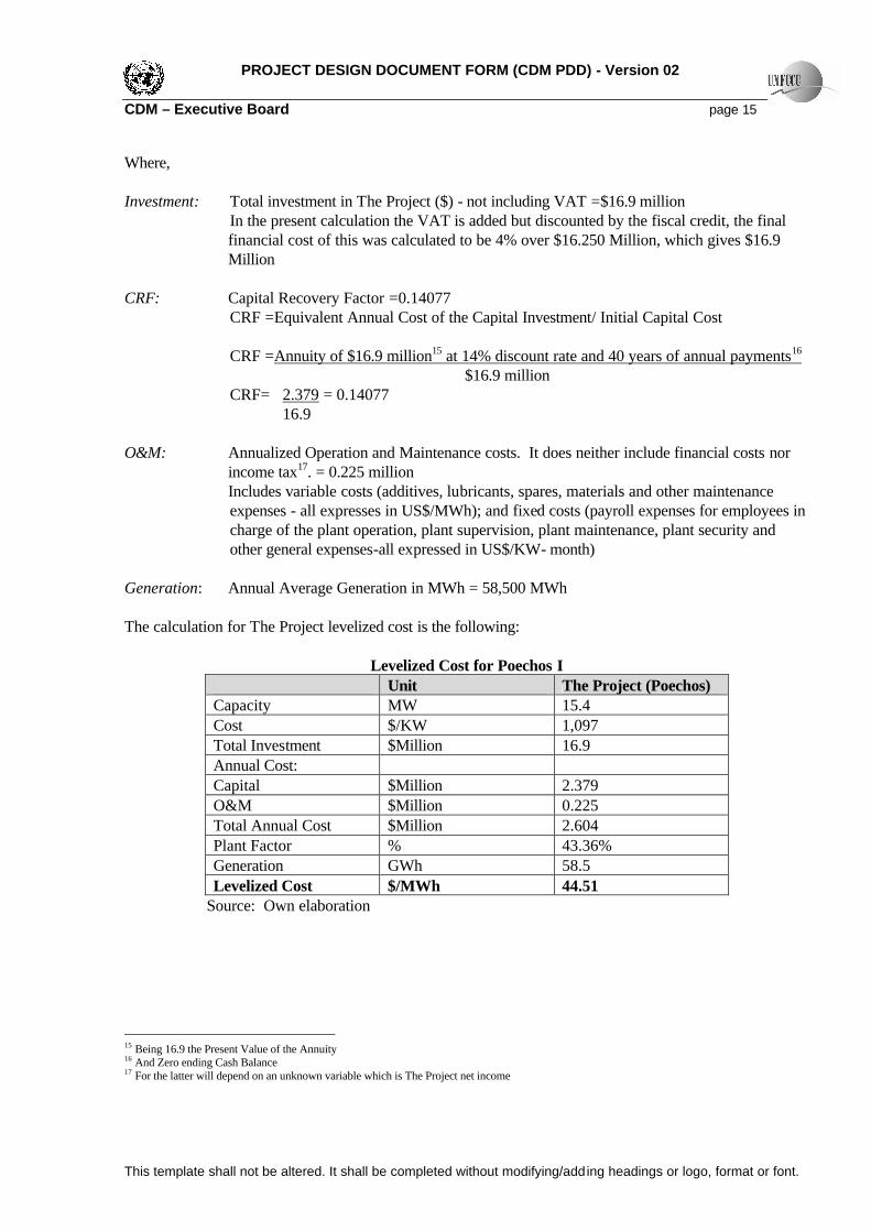
owner of the title of these activities should inform the MINEM the initiation of activities and the technical characteristics of the project and installations. F) From Article 9 – The Peruvian Government preserve the environmental conservation and the Cultural Patrimony of the Nation, as well as the rational use of the natural resources in the development of activities related to generation, transmission and distribution of electricity. Because none of the identified alternatives breaks any legal or regulatory requirement, including the fact that none of the three are posed to go against technical norms and dispositions of environmental conservation and Cultural Patrimony conservation, all 3 scenarios are in compliance with all applicable laws and regulations and are also realistic and credible alternatives available to the project participants - Meaning The Project is additional under Step 1. Step 2 – Investment Analysis to determine that the proposed activity is not the most economically or financially attractive: This analysis shows why the proposed project activity is economically and financially less attractive than other alternatives identified, without the revenue from the sale of CERs. To conduct the investment analysis the following four sub-steps were taken: Sub-step 2a. Determine an appropriate analysis method The CDM project activity generates financial and economic benefits other than CDM related income, therefore the Cost Analysis (Option I) cannot be taken. Out of the comparison analysis (option II) and the benchmark analysis (Option III), the benchmark analysis (Option III) was chosen. Sub-step 2b - Option III. Apply the benchmark analysis The identified financial indicator is: Unit cost of service ($/MWh) The indicator for The Project is: Levelized cost of electricity production ($/MWh) The relevant benchmark value is the SEIN Long Run Marginal Cost ($/MW). Both unit cost of service ($/MWh) include cost of investment, operation and maintenance and reflect a Present Value $/MWh. The benchmark represents standard costs in the market, considering the specific risk of the project type (power generation), and it is not linked to the subjective profitability expectation or risk profile of a particular project developer. That The Project is not the most inexpensive alternative in the market will be demonstrated in Sub-step 2c. Sub-step 2c – Calculation and comparison of financial indicators14 Calculation of the levelized cost of The Project, which includes Investment (I) and Operation and Maintenance (O&M) Costs Levelized Cost of The Project: The formula to calculate the levelized cost is the following: Cost per MWh = [Investment x CRF + O&M Annual] /Annual Generation (MWh) 14 Detailed data for calculation and modeling of Minimum Cost Expansion Plan is in Annex 3 under “Details of LRMC variables”
PROJECT DESIGN DOCUMENT FORM (CDM PDD) - Version 02 CDM – Executive Board page 15
This template shall not be altered. It shall be completed without modifying/adding headings or logo, format or font.
Where, Investment: Total investment in The Project ($) - not including VAT =$16.9 million
In the present calculation the VAT is added but discounted by the fiscal credit, the final financial cost of this was calculated to be 4% over $16.250 Million, which gives $16.9 Million
CRF: Capital Recovery Factor =0.14077
CRF =Equivalent Annual Cost of the Capital Investment/ Initial Capital Cost CRF =Annuity of $16.9 million15 at 14% discount rate and 40 years of annual payments16 $16.9 million CRF= 2.379 = 0.14077
16.9 O&M: Annualized Operation and Maintenance costs. It does neither include financial costs nor
income tax17. = 0.225 million Includes variable costs (additives, lubricants, spares, materials and other maintenance expenses - all expresses in US$/MWh); and fixed costs (payroll expenses for employees in charge of the plant operation, plant supervision, plant maintenance, plant security and other general expenses-all expressed in US$/KW- month)
Generation: Annual Average Generation in MWh = 58,500 MWh The calculation for The Project levelized cost is the following:
Levelized Cost for Poechos I Unit The Project (Poechos) Capacity MW 15.4 Cost $/KW 1,097 Total Investment $Million 16.9 Annual Cost: Capital $Million 2.379 O&M $Million 0.225 Total Annual Cost $Million 2.604 Plant Factor % 43.36% Generation GWh 58.5 Levelized Cost $/MWh 44.51
Source: Own elaboration
15 Being 16.9 the Present Value of the Annuity 16 And Zero ending Cash Balance 17 For the latter will depend on an unknown variable which is The Project net income
PROJECT DESIGN DOCUMENT FORM (CDM PDD) - Version 02 CDM – Executive Board page 16
This template shall not be altered. It shall be completed without modifying/adding headings or logo, format or font.
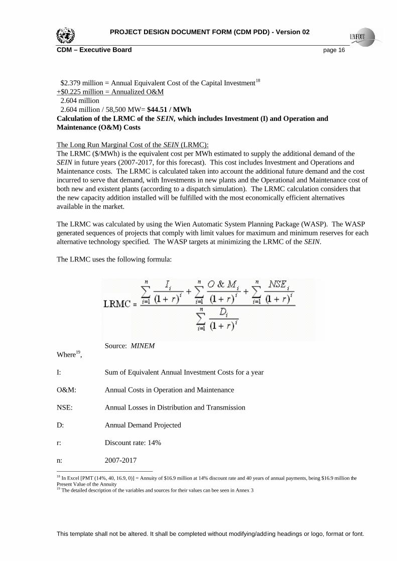
$2.379 million = Annual Equivalent Cost of the Capital Investment18 +$0.225 million = Annualized O&M 2.604 million 2.604 million / 58,500 MW= $44.51 / MWh Calculation of the LRMC of the SEIN, which includes Investment (I) and Operation and Maintenance (O&M) Costs The Long Run Marginal Cost of the SEIN (LRMC): The LRMC ($/MWh) is the equivalent cost per MWh estimated to supply the additional demand of the SEIN in future years (2007-2017, for this forecast). This cost includes Investment and Operations and Maintenance costs. The LRMC is calculated taken into account the additional future demand and the cost incurred to serve that demand, with Investments in new plants and the Operational and Maintenance cost of both new and existent plants (according to a dispatch simulation). The LRMC calculation considers that the new capacity addition installed will be fulfilled with the most economically efficient alternatives available in the market. The LRMC was calculated by using the Wien Automatic System Planning Package (WASP). The WASP generated sequences of projects that comply with limit values for maximum and minimum reserves for each alternative technology specified. The WASP targets at minimizing the LRMC of the SEIN. The LRMC uses the following formula:
Source: MINEM Where19, I: Sum of Equivalent Annual Investment Costs for a year O&M: Annual Costs in Operation and Maintenance NSE: Annual Losses in Distribution and Transmission D: Annual Demand Projected r: Discount rate: 14% n: 2007-2017 18 In Excel [PMT (14%, 40, 16.9, 0)] = Annuity of $16.9 million at 14% discount rate and 40 years of annual payments, being $16.9 million the Present Value of the Annuity 19 The detailed description of the variables and sources for their values can bee seen in Annex 3

PROJECT DESIGN DOCUMENT FORM (CDM PDD) - Version 02 CDM – Executive Board page 17
This template shall not be altered. It shall be completed without modifying/adding headings or logo, format or font.
Calculation of LRMC of The SEIN
Year Demand GWh
Incremental Demand
GWh
I20 1000$
O&M21 1000$
NSE 1000 US$
Total Cost 1000 US$
2006 23219.4 - - - - - 2007 24061.9 843 8,853 14,740 0 23,593 2008 24935.4 1,716 36,165 9,770 0 45,935 2009 25789.3 2,570 36,165 34,340 0 70,505 2010 26681.4 3,462 45,018 48,480 0 93,498 2011 27587.9 4,369 72,329 47,190 0 119,519 2012 28548.6 5,329 72,329 67,870 0 140,199 2013 29539.3 6,320 108,494 75,870 0 184,364 2014 30563.2 7,344 108,494 92,510 0 201,004 2015 31618.3 8,399 108,494 113,000 0 221,494 2016 32709.9 9,491 117,347 137,600 0 254,947 2017 33839.2 10,620 144,658 145,150 0 289,808
NPV (14%) 20,435 296,326 260,281 - 556,607 LRMC 27.24 $/MWh
Source: Own elaboration 556,607/20,435 = $27.24 The resulting LRMC of the SEIN was $27.24 /MWh. Comparison: Both the LRMC and the Project levelized cost are comparable because they have the same nature of components (both I and O&M) and both reflect a present value of $/MWh. From the results obtained: $44.51 per MWh > $27.24 per MWh, we can say that The Project is not the most financially attractive investment alternative because it has a higher cost indicator than the benchmark. Furthermore, this analysis proves not only that The Project is a more expensive alternative than the benchmark but a less profitable alternative, with the assumption that the price $/MWh generators charge is similar among generators, regardless of the technology they use. Sub-step 2d. Sensitivity Analysis The following variables will undergo a sensitivity analysis to prove the robustness of the conclusion given in Sub-step 2c. For the SEIN LRMC ($/MWh)22: a) Annual Investment costs b) Discount Rate For The Project Levelized Cost ($/MWh): a) Load Factor b) The Initial Investment Cost
20 Equivalent Annual Cost of Capacity Additions selected by WASP 21 Simulation of future supply to attend the projected demand was forecasted by WASP 22 Note that a sensitivity analysis can not be performed for the LRMC Load Factor, because in the LRMC calculation, the load factor varied per plant, per month, and per year

PROJECT DESIGN DOCUMENT FORM (CDM PDD) - Version 02 CDM – Executive Board page 18
This template shall not be altered. It shall be completed without modifying/adding headings or logo, format or font.
c) Discount Rate Sensitivity Analysis for the SEIN LRMC ($27.24/MWh)
DataY 12% 14% 16% r=0% 90% 100% 120% 12% 14% 16% 12% 14% 16% 12% 14% 16%
2007 672 649 626 843 21,234 23,593 28,312 16,927 16,339 15,780 18,808 18,154 17,533 22,570 21,785 21,040 2008 1221 1158 1099 1,716 41,342 45,935 55,122 29,426 27,904 26,486 32,696 31,005 29,429 39,235 37,206 35,314 2009 1633 1522 1419 2,570 63,455 70,505 84,606 40,326 37,570 35,045 44,807 41,745 38,939 53,769 50,094 46,727 2010 1964 1798 1648 3,462 84,148 93,498 112,198 47,748 43,704 40,064 53,053 48,560 44,516 63,664 58,272 53,419 2011 2213 1990 1793 4,369 107,567 119,519 143,423 54,497 49,006 44,150 60,552 54,451 49,056 72,662 65,341 58,867 2012 2411 2130 1886 5,329 126,179 140,199 168,239 57,077 50,426 44,646 63,419 56,029 49,607 76,103 67,235 59,528 2013 2553 2216 1928 6,320 165,928 184,364 221,237 67,015 58,167 50,612 74,462 64,630 56,236 89,354 77,557 67,483 2014 2648 2258 1931 7,344 180,904 201,004 241,205 65,236 55,629 47,569 72,484 61,810 52,855 86,981 74,172 63,426 2015 2704 2266 1904 8,399 199,345 221,494 265,793 64,184 53,772 45,188 71,315 59,747 50,209 85,578 71,696 60,251 2016 2728 2246 1855 9,491 229,452 254,947 305,936 65,962 54,292 44,839 73,291 60,325 49,821 87,949 72,390 59,785 2017 2726 2204 1789 10,620 260,827 289,808 347,770 66,948 54,137 43,940 74,386 60,152 48,822 89,264 72,183 58,586
23,475 20,436 17,879 60,463 575,346 500,947 438,319 639,274 556,608 487,021 767,128 667,930 584,426 90%*I 12% 24.51 9.21
14% 24.5116% 24.52
100%*I 12% 27.2314% 27.2416% 27.24
120%*I 12% 32.6814% 32.6816% 32.69
120%*IIncremental GWh
r=0%EAI=Eq.Annual Invest Cost Discount Rate Sensitivity
100%*I90%*I
SENSITIVITY ANALYSIS FOR THE SEIN LRMC (2007-2017)
NPV of Annual Investments=
Source: Own elaboration Sensitivity analysis for The Project ($44.51/MWh)
LF100% 120% 110% 90% 80%
Capacity MW 15.4 15.4 15.4 15.4 15.4Cost $/KW 1,097 1,097 1,097 1,097 1,097Total Investment $Million 16.9 16.9 16.9 16.9 16.9
Annual Cost:
Capital $Million $2.38 2.38 2.38 2.38 2.38O&M $Million 0.225 0.225 0.225 0.225 0.225Total Annual Cost $Million $2.60 2.604 2.604 2.604 2.604
Plant Factor %43.36% 52.04% 47.70% 39.03% 34.69%
Generation MWh 58,500 70,200 64,350 52,650 46,800
Levelized Cost $/MWh 44.51 37.09 40.46 49.45 55.63
14% Discount Rate
SENSITIVITY ANALYSIS FOR THE PROJECT LEVELIZED COST ($/MWh)40 years of payment Change in Load Factor (LF*%)16.9 Investment Cost all else constant
Source: Own elaboration
Load factor-initial investment cost-discount rate Sensitivity Analysis Matrix:

PROJECT DESIGN DOCUMENT FORM (CDM PDD) - Version 02 CDM – Executive Board page 19
This template shall not be altered. It shall be completed without modifying/adding headings or logo, format or font.
LEVELIZED COST COMPONENTS: 52.04% 47.70% 39.03% 34.69%
EAI Capital Cost 15.21 I*90% 12% ($1.85) ($1.85) ($1.85) ($1.85)Figures are in red only 14% ($2.14) ($2.14) ($2.14) ($2.14)because they represent 16% ($2.44) ($2.44) ($2.44) ($2.44)
outflows (costs) 16.90 I*100% 12% ($2.05) ($2.05) ($2.05) ($2.05)14% ($2.38) ($2.38) ($2.38) ($2.38)16% ($2.71) ($2.71) ($2.71) ($2.71)
20.28 I*120% 12% ($2.46) ($2.46) ($2.46) ($2.46)14% ($2.85) ($2.85) ($2.85) ($2.85)
+ $0.225 million = Total EAC 16% ($3.25) ($3.25) ($3.25) ($3.25)
Total Equivalent Annual Cost 15.21 I*90% 12% 2.070 2.070 2.070 2.07014% 2.366 2.366 2.366 2.36616% 2.665 2.665 2.665 2.665
16.90 I*100% 12% 2.275 2.275 2.275 2.27514% 2.604 2.604 2.604 2.60416% 2.936 2.936 2.936 2.936
20.28 I*120% 12% 2.685 2.685 2.685 2.68514% 3.079 3.079 3.079 3.07916% 3.478 3.478 3.478 3.478
Levelized Cost 15.21 12% 29.49 32.17 39.32 44.23 14% 33.70 36.76 44.93 50.55
Total EAC $ /Annual Generation (MWh) 16% 37.96 41.41 50.62 56.95 16.90 12% 32.41 35.35 43.21 48.61
14% 37.09 40.46 49.45 55.63 16% 41.83 45.63 55.77 62.74
20.28 12% 38.25 41.73 51.00 57.37 14% 43.86 47.85 58.49 65.80 16% 49.55 54.05 66.07 74.32
LOAD FACTOR
Source: Own elaboration
Comparing all Levelized Cost obtained with all benchmarks obtained:
Change in Investmentfor Poechos 120% 110% 90% 80%
Max EAI for the SEIN 15.21 12% Not Additional Not Additional Additional Additional32.69 14% Additional Additional Additional Additional
16% discount rate 16% Additional Additional Additional Additional120% Investment Cost 16.9 12% Not Additional Additional Additional Additional
14% Additional Additional Additional Additional16% Additional Additional Additional Additional
20.28 12% Additional Additional Additional Additional14% Additional Additional Additional Additional16% Additional Additional Additional Additional
and its I is reduced in 10% to $15.21 million (since the latter is not plausible, this scenario can be discarded)
Discount Ratefor Poechos
and it keeps having a $16.9 million in initial investment cost - however, at this scenario Poechos is only 0.9% less-expensive ($/MWh)
Change in Load Factor for Poechos (LF*%)Benchmark- Not efficient Market
3) Poechos is more efficient than the market when its LOAD FACTOR increases to 52.04%, faces DISCOUNT RATE of 12% and its I is reduced in 10% to $15.21 million (since the latter is not plausible, this scenario can be discarded)2) Poechos is more efficient than the market when its LOAD FACTOR increases to 47.7%, faces DISCOUNT RATE of 12%
1) Poechos is more efficient than the market when its LOAD FACTOR increases to 52.04%, faces DISCOUNT RATE of 12%

PROJECT DESIGN DOCUMENT FORM (CDM PDD) - Version 02 CDM – Executive Board page 20
This template shall not be altered. It shall be completed without modifying/adding headings or logo, format or font.
Change in Investment
for Poechos 120% 110% 90% 80%Medium EAI for the SEIN 15.21 12% Additional Additional Additional Additional
27.24 14% Additional Additional Additional Additional16% discount rate 16% Additional Additional Additional Additional
120% Investment Cost 16.9 12% Additional Additional Additional Additional14% Additional Additional Additional Additional16% Additional Additional Additional Additional
20.28 12% Additional Additional Additional Additional14% Additional Additional Additional Additional16% Additional Additional Additional Additional
Change in Investmentfor Poechos 120% 110% 90% 80%
Min EAI for the SEIN 15.21 12% Additional Additional Additional Additional24.52 14% Additional Additional Additional Additional
16% discount rate 16% Additional Additional Additional Additional120% Investment Cost 16.9 12% Additional Additional Additional Additional
14% Additional Additional Additional Additional16% Additional Additional Additional Additional
20.28 12% Additional Additional Additional Additional14% Additional Additional Additional Additional16% Additional Additional Additional Additional
Benchmark- Most efficient MarketChange in Load Factor (I*%)
Discount Ratefor Poechos
Discount Ratefor Poechos
Benchmark- Base Scenario MarketChange in Load Factor (I*%)
Source: Own elaboration All combination for both scenarios, indicate that The Project is additional except for only three cases: -When comparing with a Not Efficient Market Benchmark ($32.69), when r=12% and The Project Initial Investment Cost goes down by 10% and Load Factors for The Project go up in 10% and 20% - These two scenarios can be discarded because it was not possible to decrease the cost of The Project less than $16.9 million -When comparing with a Not Efficient Market Benchmark ($32.69), when r=12%, the Initial Investment Cost of The Project is kept and The Project Load Factor go up in 20% - The hydrological conditions that this scenario implies are not likely to be sustainable in the life of The Project, so it can also be discarded. Both benchmarks, the Medium Efficiency Scenario for the Market and the Most Efficient Scenario for the Market, show that The Project is additional at all discount rates, at all load factors and at all initial investment costs, considered for it. Hence, the conclusion that The Project is less financially attractive than other alternatives is robust to reasonable variations in the critical assumptions. The Project is unlikely to be the most financially attractive alternative in terms of costs; and in terms of profitability keeping the assumption that the price ($/MWh) that generators charge is similar among them, regardless of the technology they use: hydro or gas, which is not a far-fetched assumption given that both technologies have equal access to all the Peruvian territory final energy-users – Meaning the Project is additional under Step 2. Step 3. Barrier Analysis Sub-step 3 a. Identify barriers that would prevent the implementation of the type of the proposed project activity Hydropower plants projects face several types of barriers that prevent them from being carried out if they are not registered as CDM activities. The barriers The Project faced were basically two:

PROJECT DESIGN DOCUMENT FORM (CDM PDD) - Version 02 CDM – Executive Board page 21
This template shall not be altered. It shall be completed without modifying/adding headings or logo, format or font.
1) A still depressed international investment climate towards emerging markets when The Project started construction in late 2002: A worldwide flight-to-quality phenomenon affected Peru from late 1998 – in 2 ways, preventing international investors to lend to the Peruvian banking system and preventing the Peruvian banking system to lend to highly leveraged projects (commonly highly capital intensive projects) that do not have large companies as project developers (The Project case). The flight to quality worldwide phenomenon was triggered by the successive global emerging markets crisis, which started in 199723, “private capital flows to emerging markets had all dried up by 2001”24. Graphs below show the effects of the emerging market crisis. The Project Developer counted with the CERs before October 2002 -a preliminary PDD was elaborated in February 2002- thus the promise of this future revenue helped to cope with the international climate. The loan agreement to fund The Project was signed in October 2002 fully integrating Carbon Finance cash flows in the financial models.
Net Private Capital Inflows (1985-2003) (Billions of $)
Source: IMF, World Economic Outlook
23 Thailand crisis, July 1997; Russian Crisis August 1998; Brazil devalues and floats in February 1999; Turkey floats the lira in February 2001; Argentina defaults in December 2001 – Following the successive crises in Asia (1997) and Russia (1998) 24 The Unholy Trinity of Financial Contagion, by Kaminsky, Reinhart, and Vegh; Journal of Economics Perspectives – Volume 17-Number 4 – Fall 2003 - pg 63.

PROJECT DESIGN DOCUMENT FORM (CDM PDD) - Version 02 CDM – Executive Board page 22
This template shall not be altered. It shall be completed without modifying/adding headings or logo, format or font.
Source: Peruvian Banking and Insurance Superintendence - Nov 2002 Statistics
Source: Peruvian Banking and Insurance Superintendence - August 2004 Statistics 2) Government policies pro-Camisea natural gas project and pro- natural gas-based electricity generation: The Peruvian Government had proven to be fickle in the past regarding the Camisea Project25 as shown by its relationship with Shell - policies and acceptance towards the Camisea Project were highly dependent on the Presidential regime. However after the exit of Shell in July 1998, the successive governments have adopted a clear “pro-Camisea” position, granting a series of guarantees and incentives. The Project started constructions works in November 2002, thus it was affected by Law 27133 – Law of Promotion of the Natural Gas Industry issued in June 4, 1999, in force as of today - after laws that have slightly modified it: DS 034-2001-EM (issued in July 2001), DS 018-2000-EM (issued in October 2000). The Project has also started construction after several incentives were already given 25 San Gaban II and Yuncan constructions in 1998 show a no clear political promotion towards gas by that time of the Fujimori Government. These 2 hydroelectric power plants would produce daily the same as a natural gas-fired plant generation that uses 50 MMCFPD (almost the volume sell guaranteed under the Take or Pay). Between 1983 and 1987 as a result of drilling 5 exploration wells, Shell discovers the Camisea Gas Fields. In July 1998 the consortium Shell-Mobil announces its decision of abandoning the negotiations with Peruvian Government and, thus the contract is terminated

PROJECT DESIGN DOCUMENT FORM (CDM PDD) - Version 02 CDM – Executive Board page 23
This template shall not be altered. It shall be completed without modifying/adding headings or logo, format or font.
and/or readily in place regarding promotion in the continuity of the Camisea gas project and in electricity generation based on natural gas (i.e. TOP contract signed in December 2000). The Camisea Chronology is the following: a) During the Fujimori Regime (1990- August 2000): After the exit of Shell, in mid 1998, the Government decided to promote thermal technology based on natural gas, from that same year it halted the definitive and temporal concessions for hydropower plants through: Law 26980 issued in September 1998, Law 27133 issued in June 1999, and Law 27239 issued in December 199926. No hydropower plants definite concessions were granted in the years 1999 to 200027, showing the clear impact and determination of the Fujimori’s Laws against hydropower plants developments. In May 1999, the Special Committee for The Camisea Project (CECAM) called for an international public bid to award the license agreement for the Camisea Gas Exploitation, as well as the concession for liquids and gas transportation to the coast and gas fuel distribution in Lima and CalIao. In February 2000, pursuant to an international public bid, Fujimori’s Government awarded the license for the exploitation of the Camisea Fields (Upstream) to the Consortium Pluspetrol, led by Pluspetrol Peru Corporation S.A (the operator), with the participation of Hunt Oil Company of Peru L.L.C., SK Corporation and Tecpetrol del Peru S.A.C. (fully owned by Techint Group, an Argentinean group). The license was awarded based on the highest royalty rate offered28 - The Upstream Project consists of a 40-year license for the extraction of natural gas and liquid hydrocarbon. b) The Transitional Government of President Valentin Paniagua (set 2000-July 2001), derogated the Law 27239 Unique Complementary Disposition given by Fujimori against hydropower plant development through the Law 27435 (Hydropower Plants Concessions Promotions Law) in March 15th, 2001. But just months before the release of the issuance of Law 27435, in October 2000, the presidential regime had awarded the concessions for liquid and gas transportation to the coast and gas distribution in Lima and Callao (Downstream) to The Consortium TGP29, led by Tecgas N.V (the operator and fully owned by Techint Group), with the participation of Pluspetrol Resources Corporation, Hunt Oil Company, SK Corporation, Sonatrach Petroleum Corporation B.V.I and Graña y Montero S.A. The Downstream includes three different 33-year contracts: a contract for the transportation of gas from Camisea to Lima, a second one for the transportation of natural gas liquids from Camisea to the coast and a third one for the distribution of gas in Lima and Callao. They were awarded on the basis of the lowest service cost offered. In December 2000, The Peruvian Government represented by Electroperu, stated owned generation enterprise, acquired an important commitment aiming at providing an extra incentive for The Camisea Project. This is the contract of supply of natural gas for electricity generation (“Take or Pay” or TOP). This contract indeed fostered this Mega Project, because it meant a commitment to pay close to $20 million annually for natural gas for electricity generation purposes regardless of whether it be consumed or not30. The TOP contract aimed at helping investors in Transportation and Distribution to achieve their projected IRR of 12%, the government also allowed an increase the regulated price to the final client, for this end. On the other hand, the scheme for the Extraction business was setting maximum prices of natural gas on-site (for the electricity sector: Max Price of 1.00 US$/MMBTU for other sectors: Max Price of 1.80 US$/MMBTU, for exports 0.6 US$/MMBTU to make it competitive internationally).
26 The detail of these three laws against hydropower plant development can be seen under section A.4.4. 27 Source: Last-10-year list of definite concessions granted by the MINEM 28 The consortium Pluspetrol offered the highest royalty rate, 37.24% 29 Transportadora de Gas Del Peru S.A (TGP) is the company formed by the consortium specifically created for the development and operation of The Camisea Project Downstream 30 The TOP contract established a discount of 10% in the on−site price with respect to the price established for the other electric generators
PROJECT DESIGN DOCUMENT FORM (CDM PDD) - Version 02 CDM – Executive Board page 24
This template shall not be altered. It shall be completed without modifying/adding headings or logo, format or font.
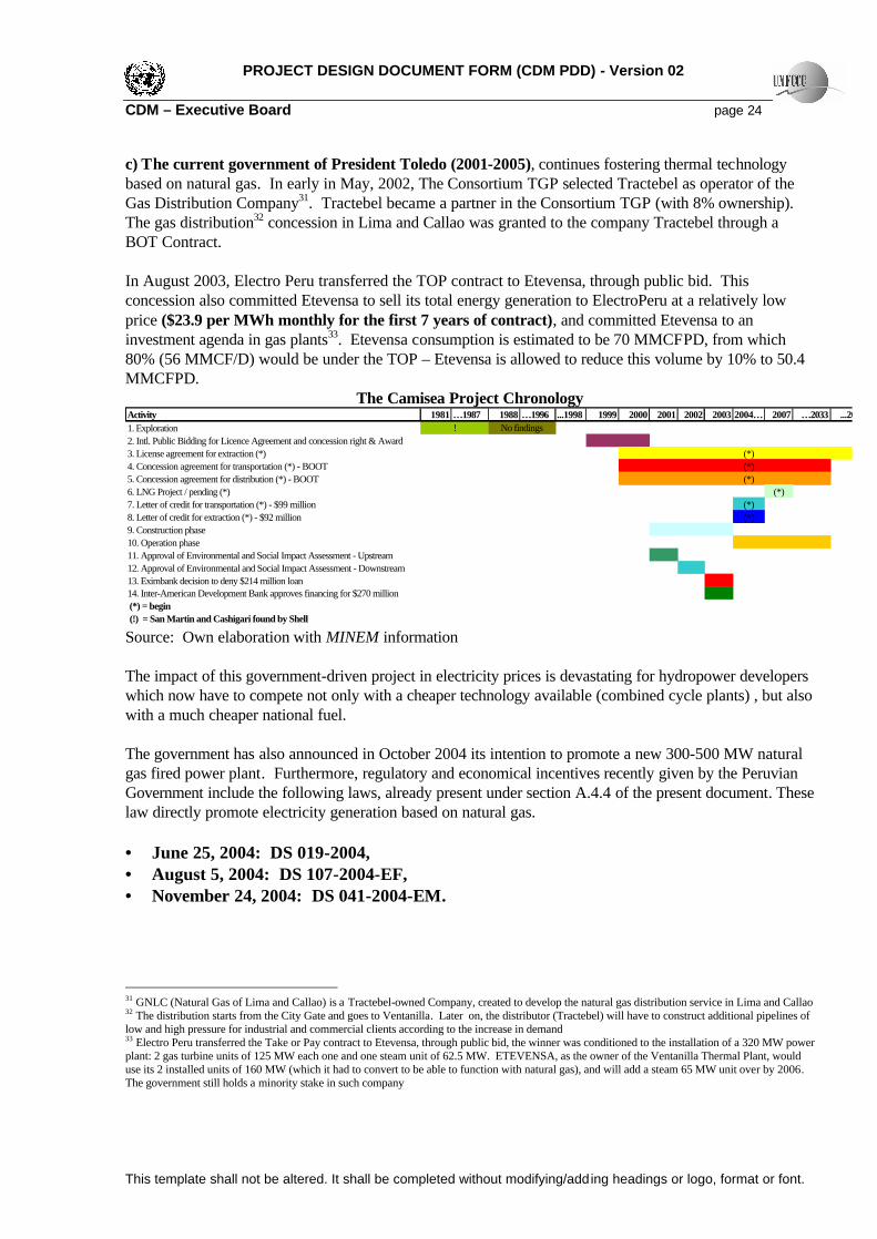
c) The current government of President Toledo (2001-2005), continues fostering thermal technology based on natural gas. In early in May, 2002, The Consortium TGP selected Tractebel as operator of the Gas Distribution Company31. Tractebel became a partner in the Consortium TGP (with 8% ownership). The gas distribution32 concession in Lima and Callao was granted to the company Tractebel through a BOT Contract. In August 2003, Electro Peru transferred the TOP contract to Etevensa, through public bid. This concession also committed Etevensa to sell its total energy generation to ElectroPeru at a relatively low price ($23.9 per MWh monthly for the first 7 years of contract), and committed Etevensa to an investment agenda in gas plants33. Etevensa consumption is estimated to be 70 MMCFPD, from which 80% (56 MMCF/D) would be under the TOP – Etevensa is allowed to reduce this volume by 10% to 50.4 MMCFPD.
The Camisea Project Chronology Activity 1981 …1987 1988 …1996 ...1998 1999 2000 2001 2002 2003 2004… 2007 …2033 ...20401. Exploration2. Intl. Public Bidding for Licence Agreement and concession right & Award3. License agreement for extraction (*) (*)4. Concession agreement for transportation (*) - BOOT (*)5. Concession agreement for distribution (*) - BOOT (*)6. LNG Project / pending (*) (*)7. Letter of credit for transportation (*) - $99 million (*)8. Letter of credit for extraction (*) - $92 million (*)9. Construction phase10. Operation phase11. Approval of Environmental and Social Impact Assessment - Upstream12. Approval of Environmental and Social Impact Assessment - Downstream13. Eximbank decision to deny $214 million loan14. Inter-American Development Bank approves financing for $270 million (*) = begin (!) = San Martin and Cashigari found by Shell
! No findings
Source: Own elaboration with MINEM information The impact of this government-driven project in electricity prices is devastating for hydropower developers which now have to compete not only with a cheaper technology available (combined cycle plants) , but also with a much cheaper national fuel. The government has also announced in October 2004 its intention to promote a new 300-500 MW natural gas fired power plant. Furthermore, regulatory and economical incentives recently given by the Peruvian Government include the following laws, already present under section A.4.4 of the present document. These law directly promote electricity generation based on natural gas. • June 25, 2004: DS 019-2004, • August 5, 2004: DS 107-2004-EF, • November 24, 2004: DS 041-2004-EM.
31 GNLC (Natural Gas of Lima and Callao) is a Tractebel-owned Company, created to develop the natural gas distribution service in Lima and Callao 32 The distribution starts from the City Gate and goes to Ventanilla. Later on, the distributor (Tractebel) will have to construct additional pipelines of low and high pressure for industrial and commercial clients according to the increase in demand 33 Electro Peru transferred the Take or Pay contract to Etevensa, through public bid, the winner was conditioned to the installation of a 320 MW power plant: 2 gas turbine units of 125 MW each one and one steam unit of 62.5 MW. ETEVENSA, as the owner of the Ventanilla Thermal Plant, would use its 2 installed units of 160 MW (which it had to convert to be able to function with natural gas), and will add a steam 65 MW unit over by 2006. The government still holds a minority stake in such company

PROJECT DESIGN DOCUMENT FORM (CDM PDD) - Version 02 CDM – Executive Board page 25
This template shall not be altered. It shall be completed without modifying/adding headings or logo, format or font.
According to the MINEM34, the foreseen Camisea impact scenarios35 in the Peruvian electricity industry are two: 1) Hydro-thermal Scenario: At the end of 2027, the SEIN will have an installed capacity 66% thermal and 34% hydro. The current situation of the installed capacity of the SEIN is 40% thermal and 60% hydro. 2) Thermal Scenario: If all the additions in electricity generation were going to be natural gas-fired thermal plants, at the end of 2027 the SEIN would have an installed capacity 75% thermal and 25% hydro. In both scenarios, the electric sector would be the main consumer of the Peruvian natural gas industry. In the hydro-thermal scenario the demand would be 800 MMCFPD, and in the thermal scenario would be 1000 MMMCFPD. From this forecast it can be concluded that Peru’s baseline in the future is Natural Gas. Sub-step 3b. Show how the identified barriers would not prevent the implementation of at least one of the alternatives Although Barrier 1) affected all types of infrastructure investments in Peru from late 1998, since the financial system plays a central role in linking savers and investors, thereby promoting investment and growth, it can certainly be said that it affected less strongly natural gas projects than hydropower plant projects, because of three reasons a) The lower investment needed to build a natural gas-fired power plant b) The faster the time it takes to put the brand-new engines in operation for the gas-fired power plant, c) The shorter time it takes in recovering the initial investment made which exposes lenders to less risks. In Peru, financial markets (basically: banking system and capital market) are dominated by short-term instruments. This tendency increased by 2002 as a consequence of the flight-to-quality phenomenon. It is much more plausible to finance gas-power plant projects by rolling over maturing short-term debt, than it is to do so for hydropower plant developments for the three reasons above mentioned. Furthermore, both fixed and variable costs taken together for The Project and for The Benchmark (composed of Natural Gas Plants) show that building a hydropower plant is more expensive overall and assuming that the price $/MWh that generators charge is similar regardless of the technology they use -which is not a far-fetched assumption given that both gas-fired power and hydropower technologies have equal access to all the Peruvian territory final energy-users- as mentioned in sub-step 2c, The Project is a less profitable alternative that a natural gas fired-power plant, which further kept investors away from The Project. Barrier 2) does not prevent the implementation of natural gas developments. In fact natural gas developments is the beneficiary of all these policies and government interventions in the electricity market and energy sector from late 1998 Barrier 1) and Barrier 2) complemented when mixed, against hydropower plants development and in favor of gas developments, making even stronger the total barriers that The Project Activity had to face. From all these barriers The Project faced, which did not prevent the implementation of a plausible alternative, natural gas development, we can conclude that The Project is additional under Step 3. Step 4. Common Practice Analysis Sub-step 4a. Analyze other activities similar to the proposed project activity
34 MINEM-Electricity General Directive, http://www.minem.gob.pe/electricidad/estadisticas/informativo/informativo8.pdf 35 Considering a 4.6% annual demand increase

PROJECT DESIGN DOCUMENT FORM (CDM PDD) - Version 02 CDM – Executive Board page 26
This template shall not be altered. It shall be completed without modifying/adding headings or logo, format or font.
Hydro-generation barriers started in the second half of 1998 because of both 1) a depressed international investment climate towards emerging markets which has not favored big infrastructure projects developments (as hydro are) access to financing, and 2) the clear governmental pro-Camisea position that started in 1998 after the exit of the Shell-Mobil. It is from the second half of 1998 that hydro development can not be considered anymore common practice. The situation for hydro power plants projects has kept worsening, as long as more governmental guarantees have been offered to the Camisea Project. Although it can not be said that the emerging market conditions will not improve in the future, it can certainly be said that hydro development participation in power generation installed capacity will keep shrinking until 2027- based on MINEM forecasts, because of the Camisea Project occurrence. Newly built hydro power plant that started operation since 1998 cannot be considered common practice, but rather sporadic especial conditions of the projects’ developers. All newly built hydropower plants that started operations from 1998 and all in-construction hydropower plants as of today will be analyzed in this section
In-construction projects (and their project generation by 200836)
Plants in construction Situation Additions in Installed Capacity (MW) Technology Estimated Annual
Generation (GWh)
2004SANTA ROSA II In construction 1.3 Hydro 6
VENTANILLA TG3 Conversion 164.1 Gas 697VENTANILLA TG4 Conversion 160.5 Gas 1,440
2005YUNCAN In construction 130 Hydro 909
Source: Own elaboration with data of GART (4-year projections of May 2004) and MINEM projection for generation of Santa Rosa II
36 Year in which annual generation of these projects stabilizes (especially the natural gas projects)

PROJECT DESIGN DOCUMENT FORM (CDM PDD) - Version 02 CDM – Executive Board page 27
This template shall not be altered. It shall be completed without modifying/adding headings or logo, format or font.
SEIN Capacity Additions from 1998 to 2003 Years Techn Addition Install.Cap.
Category Added (MW)1998AGUAYTIA 1 DRY GAS Newly built 86.3AGUAYTIA 2 DRY GAS Newly built 86.3TG MALACAS PM GAS Newly built 102.21999SAN GABAN II HYDRO Newly built 55.0CALANA R6 Newly built 6.4MOLLENDO TGM D2 Newly built 90.02000SAN GABAN II HYDRO Newly built 58.1ILO2 TVC COAL Newly built 145.0C.H. CHIMAY HYDRO Newly built 156.0C.H. YANANGO HYDRO Newly built 42.32001TUMBES R6 Newly built 18.32002C.H. HUANCHOR HYDRO Newly built 18.92003YARINACOCHA R6 Newly Built 25.6
Source: Own elaboration Yuncan Project (will start operations in 2005): The Yuncan Project, a 130 MW hydropower plant, was developed and fully owned by the Peruvian Government until June 2004. It started construction 1997, during the Fujimori Regime. The Financing for this project was given by an external loan granted to the Peruvian Government by the Japan Overseas Economic Cooperation Fund – OECF37. The total investment in the project accounts for $262.7 million. This project has been paralyzed for a number of years due to promotion of natural gas technologies and large cost overruns. On June 2004, the Government of Peru – in accordance with the local authorities of the Pasco region - granted to Enersur (Tractebel generation investment in Peru) a 30-year concession for the Yuncan hydropower plant and associated transmission facilities, keeping the same financial conditions for the new concessionary. The plant is currently under construction and is located in the Pasco Region, Central Peru, 340 km to the North East of Lima. The overall construction progress is 70% and the commissioning is estimated for July 2005. Under the usufruct agreement, Enersur has the exclusivity to operate the plant and sell the energy it generates. The financing is already given and will keep the same terms, this was a critical issue that motivated Tractebel to invest in this hydropower plant - Enersur’s offer for Yuncan was approx. $53 million to be paid over the next seventeen months. Yuncan is not comparable to SINERSA for three reasons: 1) When the government started the construction of Yuncan the international climate was not depressed as it was in 2002, 2) also Camisea was not a major strategic target of the government by that time, and 3) For Yuncan, the government access to financing (1997) is the same access to financing enjoyed by Tractebel (2004) as the government continued being the guarantor for the loan of the OECF - This is not comparable to SINERSA’s access to financing. Santa Rosa II Project (has started operations in 2004): It is a micro hydropower plant, 1.5 MW. Its sponsors applied to The World Bank to attain CDM status in early 2003. Application is currently being processed as part of the Community Development Carbon
37 This institution lends only to governments, at very low interest rates.

PROJECT DESIGN DOCUMENT FORM (CDM PDD) - Version 02 CDM – Executive Board page 28
This template shall not be altered. It shall be completed without modifying/adding headings or logo, format or font.
Fund (CDCF) and Santa Rosa II will be treated as a small scale project. Huanchor Hydropower plant (2002): Huanchor (18.9 MW) started construction in 1999. It is owned by The Grupo Gubbins. The Grupo Gubbins is a large Peruvian investment group38. The sponsor purpose was to use hydro resources that were available close to its mines. Thus, the financial returns on that project were enhanced by savings in actual electricity expenses of the sponsors’ mines (which consumes an important proportion of total Huanchor total generation). As natural gas was not available in the area surrounding the sponsor mines, the cheaper option was to build a hydropower plant. Because of the synergies Huanchor provides to its sponsor, Huanchor is not comparable to The Project. SINERSA is also not financially comparable to the Grupo Gubbins regarding access to financing. Chimay (2000) and Yanango (2000) Hydropower Plants: Commonly called “Chinango”, Chimay and Yanango account for 198.3 MW of installed capacity. The total investment was $200 million approx. The projects started constructions works in 1997, and were developed simultaneously by Edegel. Both are located approximately 125 miles east of Lima. The projects are separate facilities but do share a common transmission line, a new 120 kilometer, and a 220 kV line. This large investment was started just before the emerging markets crisis that strongly hit L.A from 199839 and in view of a good financial situation enjoyed by the sponsors, by 1997. Endesa Chile is a 37% Edegel shareholder. Enersis is a 60% Endesa-Chile shareholder, and Endesa-Spain is a 65% Enersis shareholder. Enersis’ and Endesa’s revenue for year 2003 were $3,998,967,000 and $20,899,871,000 respectively. Both sponsors are not comparable to The Project’s sponsor in access to financing, as of today, and they were certainly in a superior financial standing in 1997. Also the Chinango Project’s sponsors enjoyed a better international investment climate in 1997 than SINERSA did in 2002. The Projects started construction works prior to pro-Camisea policies. San Gaban II (1999, 2000) Hydropower Plant (2 units): Units developed and fully owned by the government (as of today), the San Gaban II hydropower plant with an installed capacity of 113.1 MW40 started its preliminary construction works in 1995. In May 1996, the civil works were called into a public bid. The winner was a Peruvian-Brazilian-French Consortium that started civil works in September 1996 and took 3 years to finish them. San Gaban II was concluded in 1999. The external financing was $155 million approx., granted by The Japan Bank for International Cooperation ($130 million) and the CAF ($25 million). The total cost of this project was $208 million. San Gaban II, is currently under 100% ownership of the Peruvian Government through FONAFE (Fondo Nacional de Financiamiento de la Actividad Empresarial del Estado). Sub-step 4b. Discuss any similar options that are occurring: No similar activities (hydropower plants) in terms of access to financing, international investment climate or developed under the same clear governmental pro-Camisea position have been identified from 1998. The only hydro power plant development that can be comparable to The Project in regards to depressed international investment climate and starting construction after the clear pro- Camisea governmental position is Huanchor, but this project activity has essential distinctions with The Project, these distinctions have been analyzed in Sub-step 4a.
38 Which has stakes in Sociedad Minera Corona (assets of $36.06 Million up to June 2004), Sociedad Minera La Cima (assets for $19.8 Million up to June 2004) and Inversiones Agricolas S.A (asset information not publicly available) 39 Russian crisis 40 Two units of approximately the same installed capacity

PROJECT DESIGN DOCUMENT FORM (CDM PDD) - Version 02 CDM – Executive Board page 29
This template shall not be altered. It shall be completed without modifying/adding headings or logo, format or font.
CER 7 years PV of Revenue$478,459
Equivalent Annual Revenue$67,341
In millions$0.07
CER 14 years PV of Revenue$669,669
Equivalent Annual Revenue$94,253
In millions$0.09
CER 21 years PV of Revenue$746,084
Equivalent Annual Revenue$105,008
In millions$0.11
LF=43.36% + CERs + CERs + CERs7 years 14 years 21 years
Capacity MW 15.4 15.4 15.4 15.4Cost $/KW 1,097 1,097 1,097 1,097Total Investment $Million 16.9 16.9 16.9 16.9Annual Cost:Income CERS $Million $0.00 ($0.07) ($0.09) ($0.11)Capital $Million $2.38 $2.38 $2.38 $2.38 O&M $Million 0.225 0.225 0.225 0.225Total Annual Cost $Million $2.60 $2.54 $2.51 $2.50 Plant Factor % 43.36% 43.36% 43.36% 43.36%Generation MWh 58,500 58,500 58,500 58,500 Levelized Cost $/MWh 44.51 43.35 42.89 42.71 CERs/yr (tCO2) 31,878 Change in $/MWh: -2.59% -3.62% -4.03%Revenue/yr ($) 111,573
SENSITIVITY ANALYSIS FOR THE PROJECT LEVELIZED COST ($/MWh)
14% Discount Rate
40 years of payment16.9 Investment Cost
For all of the above, the claim that the proposed activity is common practice is not called into question. We can conclude that The Project therefore, is not common practice but a very unusual occurrence that endangered its existence without attaining CDM Status. Meaning The Project is additional under Step 4. Step 5. Impact of CDM Registration To help cope with its financial weaknesses and risks, SINERSA decided to seek CDM assistance. After discussions with experts, SINERSA became convinced of the good prospects for The Project’s CDM status, given The Project’s GHG-free power generation. The extra cash flow from Carbon Finance helped The Project obtained financing since the loan agreement was signed in October 2002 fully integrating the CERs revenues in the financial projections. Furthermore, the lenders took into account the carbon credits to leverage The Project’s low Debt Service Coverage Ratios41, and encouraged sponsors to file for and attain CDM status. SINERSA is currently considering discounting or borrowing against the Emissions Reduction Purchase Agreement (ERPA) to satisfy its own cash outflows commitments.
Source: Own elaboration When CERs income is taken into account (as an equivalent annual revenue), The Project’s levelized-cost improves from 2.6% less expensive to 4.0% less expensive. The approval and registration of The Project as a CDM activity alleviate the economical and financial hurdles detailed in Step 2 and the identified barrier detailed in Step 3, enabling The Project to be undertaken. Meaning the project is additional under Step 5. Because all of the above steps were satisfied, the CDM Project activity is not the baseline scenario, meaning The Project is additional. B.4. Description of how the definition of the project boundary related to the baseline methodology selected is applied to the project activity:
41 Very low EBIT/Interest Expense

PROJECT DESIGN DOCUMENT FORM (CDM PDD) - Version 02 CDM – Executive Board page 30
This template shall not be altered. It shall be completed without modifying/adding headings or logo, format or font.
The only GHG included in the ER calculation is CO2. The spatial extent of The Project boundary includes all power plants connected physically to the SEIN. As of today, no electricity exports or imports have occurred in the SEIN but will be monitored if any. Although traditionally in The Project boundary, the main energy source had been hydropower, the exploitation of natural gas deposits of Camisea, has already started to mark a new stage in the use of energy in Peru. Natural gas will turn into the most attractive economic resource to generate electricity during the present and next decades. This change in the BLS will be monitored according to The Monitoring Plan. B.5. Details of baseline information, including the date of completion of the baseline study and the name of person (s)/entity (ies) determining the baseline: The baseline study was completed on 30/11/2004 by: Francisco Fernández-Asín Carbon Finance Business World Bank Washington DC USA E-mail: [email protected] SECTION C. Duration of the project activity / Crediting period C.1 Duration of the project activity: C.1.1. Starting date of the project activity: 01/11/2002 (DD/MM/YYYY) C.1.2. Expected operational lifetime of the project activity: 40y-0m C.2 Choice of the crediting period and related information: The Project activity will use a renewable crediting period. Therefore only C.2.1 will be completed. C.2.1. Renewable crediting period C.2.1.1. Starting date of the first crediting period: 01/04/2004 (DD/MM/YYYY) C.2.1.2. Length of the first crediting period: 7y-0m C.2.2. Fixed crediting period: C.2.2.1. Starting date: C.2.2.2. Length:

PROJECT DESIGN DOCUMENT FORM (CDM PDD) - Version 02 CDM – Executive Board page 31
This template shall not be altered. It shall be completed without modifying/adding headings or logo, format or font.
SECTION D. Application of a monitoring methodology and plan D.1. Name and reference of approved monitoring methodology applied to the project activity: “Consolidated monitoring methodology for zero-emissions grid-connected electricity generation from renewable sources (ACM0002)” The above methodology is hereafter referred to as the “Monitoring Methodology”. D.2. Justification of the choice of the methodology and why it is applicable to the project activity: The Project is a grid-connected zero-emission renewable power generation activity and meets all the following conditions that are stated in the Monitoring Methodology (ACM0002): • The Project supplies electricity capacity addition from hydropower source; it is a hydropower plant with
existing reservoir where the volume of the reservoir is not increased. • The Project is not an activity that involves switching from fossil fuels to renewable energy at The Project
site; • The electricity grid is clearly identified (as the SEIN) and information is publicly available on the
characteristics of the grid. No leakages were identified and hence will not be monitored. The following variables will be monitored as stipulated by the Monitoring Methodology: • Electricity generation from The Project (double checking through quality control/assurance
procedures). • The latest SEIN grid data supplied by the COES is used for the calculation of the DDA-OM, and for
the BM. Both margins are to be calculated ex-post annually based on the most recent statistics available as directed in the Monitoring Plan.

PROJECT DESIGN DOCUMENT FORM (CDM PDD) - Version 02 CDM – Executive Board page 32
This template shall not be altered. It shall be completed without modifying/adding headings or logo, format or font.
D.2. 1. Option 1: Monitoring of the emissions in the project scenario and the baseline scenario D.2.1.1. Data to be collected in order to monitor emissions from the project activity, and how this data will be archived: ID number (Please use numbers to ease cross-referencing to D.3)
Data variable
Source of data
Data unit
Measured (m), calculated (c) or estimated (e)
Recording frequency
Proportion of data to be monitored
How will the data be archived? (electronic/ paper)
Comment
D.2.1.2. Description of formulae used to estimate project emissions (for each gas, source, formulae/algorithm, emissions units of CO2 equ.) There are no project emissions. D.2.1.3. Relevant data necessary for determining the baseline of anthropogenic emissions by sources of GHGs within the project boundary and how such data will be collected and archived : ID number (Please use numbers to ease cross-referencing to table D.3)
Data variable
Source of data
Data unit Measured (m),
calculated (c), estimated (e),
Recording frequency
Proportion of data to
be monitored
How will the data be archived? 42(electronic/
paper)
Comment
42 Data should be archived for two years following the end of the crediting period

PROJECT DESIGN DOCUMENT FORM (CDM PDD) - Version 02 CDM – Executive Board page 33
This template shall not be altered. It shall be completed without modifying/adding headings or logo, format or font.
1. EGh Electricity supplied to the Grid by The Project
ENOSA or COES
(when the Operator is an active
member of COES)
MWh Directly Measured
Hourly measuremen
t and monthly
recording
100% electronic Electricity supplied by The project activity to the grid. Double check with
receipt of sales
2. EFy CO2 emission
factor of the grid
Own elaboration
tCO2/MWh
c yearly 100% electronic Calculated as a weighted sum of the OM and BM emission factors
3. EFomy CO2 Operating
Margin Emission
Factor of the grid
Own elaboration
tCO2/MWh
c yearly 100% electronic Calculated as indicated in the relevant OM baseline method (DDA-OM)
4. EFbmy CO2 Build Margin emission
factor of the grid
Own elaboration
tCO2/MWh
c yearly 100% electronic Calculated as Sum(Fi,y*COEF)/Sum(Gen m,y) over
recently built power plants defined in the baseline methodology (BM2)
6. COEFi CO2 emission
coefficient of each fuel
type i
Own elaboration
tCO2/mass or volume
unit
c yearly 100% electronic COEFs are set for all the crediting period, but COEF for technologies not previously considered will have to be calculated separately by The Project
Staff 7. Gen Hourly
electricity generation
of all units f the grid
COES MWh m Hourly measured by
monthly recording
100% electronic

PROJECT DESIGN DOCUMENT FORM (CDM PDD) - Version 02 CDM – Executive Board page 34
This template shall not be altered. It shall be completed without modifying/adding headings or logo, format or font.
8. Plant Name
Identification of power plants for the OM
COES Text e yearly 100% of set plants
electronic Identification of plants to calculate OM
9. Plant Name
Identification of power plants for the BM
COES Text e yearly 100% of set of plants
electronic Identification of plants (m) to calculate BM
11. The merit order in
which power plants are dispatched
by documented
evidence
COES Text m Weakly 100% Paper for original documents, else
electronic
Required to stack the plants in the dispatch data analysis
11a. GENimports
Electricity imports to
The Project’s electricity
system
COES KWh c yearly 100% electronic Obtained from the latest local statistics. If local statistics are not available, IEA statistics are used to determine imports.
Imports are not expected but will be monitored if any
11.b. COEFimport
s
CO2 emission
coefficient of fuels used in connected electricity systems (if
imports occur)
COES tCO2/mass or unit volume
c yearly 100% electronic Obtained from the latest local statistics. If local statistics are not available,
IPCC default values are used to calculate them
Baseline Emission Parameters numbering use ID numbers defined in the ACM0002 Methodology/Version 01’s page 13 (http://cdm.unfccc.int/EB/Meetings/015/eb15repan2.pdf.). In this “The amount of each fossil fuel consumed by each power source” is the baseline emission parameter 5; but because no information regarding amount of fuel consumed per plant/unit is publicly available in Peru it cannot be monitored. “The amount of each fossil fuel consumed by each power source” (baseline emission parameter 5) is to be implied from “Electricity generation of each power source” (baseline

PROJECT DESIGN DOCUMENT FORM (CDM PDD) - Version 02 CDM – Executive Board page 35
This template shall not be altered. It shall be completed without modifying/adding headings or logo, format or font.
emission parameter 7), for both the DDA-OM and the BM2 calculations, in the monitoring. As shows the monitoring plan, the link between both parameters is given by the Annual Plant Fuel Requirement (APFR) Formula: Gen (KWh)*3.6*10^6 / (NEC*10^12) = APFR D.2.1.4. Description of formulae used to estimate baseline emissions (for each gas, source, formulae/algorithm, emissions units of CO2 equ.) See Section E.4. for baseline emissions calculations D. 2.2. Option 2: Direct monitoring of emission reductions from the project activity (values should be consistent with those in section E). D.2.2.1. Data to be collected in order to monitor emissions from the project activity, and how this data will be archived: ID number (Please use numbers to ease cross-referencing
to table D.3)
Data variable
Source of data
Data unit
Measured (m), calculated (c), estimated (e),
Recording frequency
Proportion of data to
be monitored
How will the data be archived? (electronic/
paper)
Comment
D.2.2.2. Description of formulae used to calculate project emissions (for each gas, source, formulae/algorithm, emissions units of CO2 equ.):

PROJECT DESIGN DOCUMENT FORM (CDM PDD) - Version 02 CDM – Executive Board page 36
This template shall not be altered. It shall be completed without modifying/adding headings or logo, format or font.
D.2.3. Treatment of leakage in the monitoring plan D.2.3.1. If applicable, please describe the data and information that will be collected in order to monitor leakage effects of the project activity ID number (Please use numbers to ease cross-referencing to table D.3)
Data variable
Source of data Data
unit
Measured (m), calculated (c) or estimated (e)
Recording frequency
Proportion of data to be monitored
How will the data be archived? (electronic/ paper)
Comment
D.2.3.2. Description of formulae used to estimate leakage (for each gas, source, formulae/algorithm, emissions units of CO2 equ.) D.2.4. Description of formulae used to estimate emission reductions for the project activity (for each gas, source, formulae/algorithm, emissions units of CO2 equ.) D.3. Quality control (QC) and quality assurance (QA) procedures are being undertaken for data monitored Data (Indicate table and ID number e.g. 3.-1.; 3.2.)
Uncertainty level of data (High/Medium/Low)
Explain QA/QC procedures planned for these data, or why such procedures are not necessary.
1 Low Sales record to the grid (COES) or final client (ENOSA) and other records are used to ensure consistency Others Low IEA statistics (for energy data) are used to check local data D.4 Please describe the operational and management structure that the project operator will implement in order to monitor emission reductions and any leakage effects, generated by the project activity No especial monitoring equipment is needed. The WB CFB will provide SINERSA with a Monitoring Plan and pre-programmed spreadsheets so The Project sponsor will just need to collect the information as described and apply the formulas as directed in the Monitoring Plan. The collection sources of the data will

PROJECT DESIGN DOCUMENT FORM (CDM PDD) - Version 02 CDM – Executive Board page 37
This template shall not be altered. It shall be completed without modifying/adding headings or logo, format or font.
not be in any case the Project own records but the final client records of hourly production to keep the highest transparency and accuracy of the data. When The Project Operator is an active member of COES the Project generation data will come from COES. The Project Staff designated will confirm these data with own records and own records will be double checked with sales receipts. D.5 Name of person/entity determining the monitoring methodology:
The Monitoring Methodology and Monitoring Plan were completed on 30/11/2004 by: Francisco Fernández-Asín World Bank Carbon Finance Business Washington, DC, USA, USA. E-mail: [email protected]

PROJECT DESIGN DOCUMENT FORM (CDM PDD) - Version 02 CDM – Executive Board page 38
This template shall not be altered. It shall be completed without modifying/adding headings or logo, format or font.
SECTION E. Estimation of GHG emissions by sources E.1. Estimate of GHG emissions by sources: The Project shall be responsible for zero GHG emissions. Hydropower plants built over existing reservoirs where the volume of the reservoir is not increased are classed as zero emission projects and there are no associated emissions in The Project boundary. E.2. Estimated leakage: The Project is not responsible for any leakage. E.3. The sum of E.1 and E.2 representing the project activity emissions: The Project is not responsible for any project activity emissions. Project activity emissions are zero (0) because there are no anthropogenic emissions or leakage. E.4. Estimated anthropogenic emissions by sources of greenhouse gases of the baseline: The Methodology stipulates that the Baseline of The Project is the Combined Margin emission factor (CM), which is the average of the Operating Margin emission factor (OM) and the Build Margin emission factor (BM) . Estimated anthropogenic emissions were calculated for The Project following a 4-step-process: Step 1 – Calculation of the Operating Margin emission factor (OM) Step 2 – Calculation of the Build Margin emission factor (BM) Step 3 – Calculation of the Baseline emission factor (CM) Step 4 – Calculation of The Project’s Emissions Reductions Prior to Validation Step 1 – Calculation of the Operating Margin emission factor Out of four options for the OM, the Dispatch Data Analysis Operating Margin Emission Factor (DDA-OM) was taken; as it constitutes the first methodological choice where data is available, according to The Methodology. The formula for the DDA-OM used was provided by The Methodology: EF_OMy Dispatch Data (tCO2/MWh)= E_OMy/EGy E_OMy = Sum of [average tCO2/MWh emitted by plants that fall within top 10% of grid dispatch each hour of the year “times” The Project generation in MWh each hour of the year] EGy = The Project Generation in the year For this calculation the BLS used the units’ hourly generation of 2003, which was the most recent statistic data available. Because at the time the BLS was completed, The Project hourly generation data for a whole year was inexistent, it was assumed that The Project operated at full capacity and dispatched equally during all hours of the year. Considering this assumption, the variables were defined as follows: -EGy: An “approximation” to MWh generated in 2003 by The Project - was obtained from multiplying Installed Capacity (MWh) of The Project times 8760. -EGh: An “approximation” to MWh generated in each hour of 2003 - assumes that The Project produces at its full installed capacity (15.4MWh) each hour.

PROJECT DESIGN DOCUMENT FORM (CDM PDD) - Version 02 CDM – Executive Board page 39
This template shall not be altered. It shall be completed without modifying/adding headings or logo, format or font.
-Fi,n,h: Electricity output in MWh hourly produced in 2003 by each unit of the SEIN that fall within the top 10% of grid dispatch. -COEFi,n43: The tCO2/MWh factors assigned to each unit of the SEIN according to its technology – For hydropower plants the COEF = 0. The information of the hourly generation of all SEIN units and their COEF associated was organized in columns (in EXCEL), where the position of the columns was sorted according to a “monthly grid dispatch merit order” calculated44. This organization helped to identify the plants that fall within top 10% of grid dispatch each hour of the year. The BLS’s resulting Dispatch Data Analysis Operating Margin emission factor was 0.72614 tCO2/MWh and was obtained from dividing E_OMy by EGy =97,960/134,940
E_OMy: SUM Egh*EF_DDh 97,960 134,904 :EGy EOMy/Egy: Operating Margin DDA_OM 0.72614 :EF_OMy DD (TCO2/MWh)
Source: Own elaboration Step 2 – Calculation of the Build Margin emission factor According to the Methodology, the BM is defined as the generation-weighted average emission factor of either the 5 most recent or the most recent 20% of power plants built (in generation), whichever group’s annual generation is greater. Both lists of plants should exclude CDM-Status Plants45. Out of the 2 options for the BM, option 2 was selected for the sake of conservativeness; this option does not include in-construction plants in the samples and requires an annual ex-post calculation for the first crediting period. The formula applied to the selected sample was: EF_BMy (tCO2/MWh) = [•I,m Fi,m,y,*COEFi,m] / [•mGENm,y] F=Generation of each plant of the selected sample COEF=tCO2/MWh of each plant of the selected sample; GEN=Generation of each plant of the selected sample In the BLS, any increase in installed capacity in the SEIN was identified and considered only if the increase was made in new units added (No: upgrades, rehabilitations or interconnections of old units). The following list shows the capacity additions (new units’) in the SEIN from 1988 to 2003, and their annual generation. As The Project did not generate yet, the annual generation of the additions taken was the average of their three most recent year’s generations.
Newly Built = Only when new units are added - interconnectionof units less than 5 years old are included
Interconnection = Old unit that gets interconnected to SEIN
Rehabilitation = Reconstruction of a plant that was broken down
Upgrade = Same unit that increases its installed capacityby technological improvements or adjustments
Classification of SEIN Addition in Installed Capacity (MW)
43 COEFs assigned to each unit of the SEIN according to their technology can be seen in Annex 3 using IPCC 1996 values 44 This was done by a simple average of the four weekly Santa Rosa Equivalent Cost Soles/MWh (merit orders) assigned to each unit of the SEIN, by COES, in a month 45 The Project is currently the only CDM-Status Plant of the SEIN

PROJECT DESIGN DOCUMENT FORM (CDM PDD) - Version 02 CDM – Executive Board page 40
This template shall not be altered. It shall be completed without modifying/adding headings or logo, format or font.
Source: Own elaboration Generation of Additions to the SEIN (1988-2003)46
Years Techn Addition Install.Cap. 2001 Gen 2002 Gen 2003 Gen Annual GenerationCategory Added (MW) (GWh) (GWh) (GWh) (GWh)
1988C.H. CARHUAQUERO HYDRO Newly built 75.1 469.27 479.41 458.78 469.16CHARCANI (I-V) HYDRO Newly built 136.80 842.17 641.80 660.24 714.741993TG VENTANILLA 2 D2 Newly built 100 2.40 2.45 1.54 2.13TG VENTANILLA 1 D2 Newly built 100 2.40 2.45 1.54 2.131995CALANA R6 Newly built 19.2 33.02 25.72 45.81 34.851996STA. ROSA WESTING D2 Newly built 127.7 9.41 5.61 11.60 8.881997C.H. GALLITO CIEGO HYDRO Newly built 34.0 183.53 149.71 121.79 151.68TG VENTANILLA D2 Newly built 184.0 4.41 4.51 2.83 3.92MOLLENDO MIRLESS R500 Newly built 31.7 10.98 9.53 35.37 18.631998AGUAYTIA 1 GAS Newly built 86.3 230.80 412.26 466.80 369.95AGUAYTIA 2 GAS Newly built 86.3 216.30 332.89 367.97 305.72TG MALACAS PM GAS Newly built 102.2 206.23 181.35 274.30 220.631999SAN GABAN II HYDRO Newly built 55.0 357.38 376.19 356.34 363.30CALANA R6 Newly built 6.4 11.01 8.57 15.27 11.62MOLLENDO TGM D2 Newly built 90.0 0.73 0.86 1.43 1.012000SAN GABAN II HYDRO Newly built 58.1 377.51 397.38 376.41 383.76ILO2 TVC COAL Newly built 145.0 338.78 845.93 859.44 681.38C.H. CHIMAY HYDRO Newly built 156.0 724.76 752.96 825.87 767.86C.H. YANANGO HYDRO Newly built 42.3 214.60 239.13 202.28 218.672001TUMBES R6 Newly built 18.3 22.38 20.73 27.99 24.362002C.H. HUANCHOR HYDRO Newly built 18.9 - 36.86 144.64 144.642003
YARINACOCHA R6 Newly Built 25.6 - - 56.88 144.97
% Inst Cap*TGen
Source: Own elaboration
Out of the list above, it can be seen that the 5 most recently built plants up to 2003 were: 1)Yarinacocha, 2) Huanchor, 3)Tumbes, 4)Yanango and 5) Chimay, and their comprised annual generation was 1,300.5 GWh. Because the annual generation of the 20% most recently built was greater, 3,860.08 GWh, the latter group was selected for the BM calculation. The 20% most recently built plants47, in generation, comprises the whole list above except for 1988 capacity additions in the SEIN. Because the tCO2 that each unit of the selected sample emits is a direct function of the technology it uses; The selected sample of Newly Built plants was organized (clustered) by technology and each technology’s annual electricity generation output was transformed back to its fuel consumption caloric value through the Annual Plant Fuel Requirement formula48 and multiplied by C x O49 x 44/12 (mass conversion factor). The total tCO2 per fuel type obtained was added up and the result was divided by the total generation (MWh) of the selected sample. Hence a weighted average tCO2/MWh of the selected sample was obtained.
The BLS’ resulting BM2 was 0.36371 tCO2/MWh, and was obtained from dividing total tCO2 emitted from the selected sample “by” total generation of the selected sample. 46 In the table, San Gaban appears twice because the increases on its installed capacity were 2 units, the first one was put in operation in 1999 and the
second one in 2000 – each unit generation was considered accordingly. 47 Exactly, the selected sample’s generation comprises 19.69% (or 20% rounding to the nearest integer) of 2001-2003 average annual generation of the SEIN (19,603 GWh) 48 APFR (TJ) = Gen(KWh)*3.6*10^6 / (NEC*10^12) 49 C and O use IPCC-1996 world wide values per fuel type

PROJECT DESIGN DOCUMENT FORM (CDM PDD) - Version 02 CDM – Executive Board page 41
This template shall not be altered. It shall be completed without modifying/adding headings or logo, format or font.
Technologies in Selected Sample Most Recent Year Gen (GWh) % per technology APFR C O 44/12 CO2 Emissions(tCO2)Coal 681.38 18% 7,433.28 25.80 0.980 3.67 689,124d2 18.06 0% 186.12 20.20 0.990 3.67 13,647r6 215.80 6% 1,807.54 21.10 0.990 3.67 138,445
r500 18.63 0% 204.82 21.10 0.990 3.67 15,688Dry Gas 675.68 18% 7,484.40 15.30 0.995 3.67 417,776
Pure Methane Gas 220.63 6% 2,443.85 14.50 0.995 3.67 129,282Dry Gas CC 0.00 0% 0.00 15.30 0.995 3.67 0
Hydro 2,029.91 53% 0.00 0.00 0.000 0.00 0TOTAL 3,860.08 100% 1,403,961
BM2= 0.36371 tCO2//MWh
Source: Own elaboration Step 3 – Calculation of the Baseline emission factor The Baseline Emission Factor was calculated as a combined margin (CM), consisting of the simple average50 of both the resulting OM and the resulting BM. All margins are expressed in tCO2/MWh. CM = 0.5*OM + 0.5*BM CM = 0.5*(0.72614) + 0.5*(0.36371) = 0.54493 tCO2/MWh The BLS’s resulting Baseline Emission Factor was 0.54493 tCO2/MWh. Step 4 – Calculation of The Project’s Emissions Reductions Prior to Validation Because The Project itself does not produce any emission , no leakages entered into the calculation of estimated ERs, and the baseline emissions were estimated to be equal to The Project ERs The estimated ERs per year for The Project were obtained from the following multiplication: Estimated Baseline Emissions = CM* (Estimated Annual Project Generation in MWh) Estimated ERs per year = CM* (Estimated Annual Project Generation in MWh) Estimated ERs per year = 0.54493 tCO2/MWh * 58,500 MWh = 31,878 tCO2 or 31,878 ERs Assuming the 3 most recent years (data used for the BSL calculations) were average years in hydrological conditions. The ERs per year estimated for the first crediting period are: Estimated ERs for the first crediting period = 31,878 tCO2/yr* 7 yrs = 223,146 tCO2 or Estimated ERs51. E.5. Difference between E.4 and E.3 representing the emission reductions of the project activity: The ERs of The Project equal the baseline emissions because The Project itself does not produce any emission. E.6. Table providing values obtained when applying formulae above:
Year Total baseline emissions (tCO2e) Total Project emissions (tCO2e) ERs(tCO2e)
2005 31,878 0 31,878 2006 31,878 0 31,878 2007 31,878 0 31,878 2008 31,878 0 31,878 2009 31,878 0 31,878 2010 31,878 0 31,878 2011 31,878 0 31,878 Total 223,146 0 223,146
50 The default weights (50%,50%) were kept 51 All margins were rounded to the fifth decimal, but the CERs per year was rounded down to the nearest integer

PROJECT DESIGN DOCUMENT FORM (CDM PDD) - Version 02 CDM – Executive Board page 42
This template shall not be altered. It shall be completed without modifying/adding headings or logo, format or font.
SECTION F. Environmental impacts F.1. Documentation on the analysis of the environmental impacts, including transboundary impacts: An EIA was a legal requirement for The Project. ECL’s Article 25 lists the EIA as a requirement to obtain a definitive concession from the MINEM. The Project needed a definitive concession to be granted by the MINEM52, because it attained the construction and operation of an electricity generation activity of more than 10 MW of installed capacity. Numerous environmental assessment documents were completed during preparation of The Project. An EIA was completed for the hydropower project specifically, which analyzed impacts during construction and operation. In part due to the highly intervened surroundings, no major impacts were identified. Construction impacts were well managed through proper environmental practices, as enumerated in an Environmental Management Plan submitted and approved by IDB, DEG and The World Bank - all financiers involved in the Project. A separate EIA was completed for the transmission line, with, again, no major impacts identified. Communities along the transmission line were given the opportunity to connect to the line. The Project has lately installed a 22.9 KV keys yard to feed 3 small isolated systems: The Lancones system, The Chira system, and a third one that goes into a small population located close to the Ecuadorian border. These three small populations’ consumptions will be partly “subsidized” by the Peruvian Government according to The Department of Energy and Mines overall initiative regarding social development and rural electrification: FOSE53 and Rural Electrification Plan, respectively. Other direct beneficial effects resulting from The Project include: -Supply of a clean source of energy; -Training to locals on the adequate uses of electricity; -Tax collections in the project area will boost the availability of funds for the development of local communities at an estimated annual average of 500,000 USD; -Creation of more than 200 jobs during the construction phase, employing exclusively locals impacting positively more than 200 families; -Contribution to the domestic capacity building efforts in environmentally sound technologies (EST) promoting the participation of local companies in the project activity including the manufacturing, for the first time in Peru, of Kaplan turbines. -Creation of around 30 permanent positions for the operation of the hydroelectric plant transferring know how in operation, maintenance and control of hydroelectric equipment and systems. These positions will utilize locally hired staff who will be trained during the construction phase; -Development of the poorest zones of the country, which using electricity will have the opportunity to start productive activities. Initially these will be promoted through the maximum use of local supplies; -First project in the Ecuadorian - Peruvian border, which will serve as a good reference projects for future initiatives for the sustainable development of this area with low human development indexes (HDI); -Mitigate the migration of peasants to the coastal cities of Peru; -SINERSA has expressed its commitment to education and local technical training; 52 Articles 3 and 24 of ECL define in which cases “a concession” and “a definitive concession” are required, respectively 53 Fondo de Compensacion Social Electrica – was created by Law 27510 in 2001. Currently FOSE’s life is set until December 2006. The FOSE was created to favor electricity access and permanency of it to all clients that consume less than 1000 KWh., by providing them discounts

PROJECT DESIGN DOCUMENT FORM (CDM PDD) - Version 02 CDM – Executive Board page 43
This template shall not be altered. It shall be completed without modifying/adding headings or logo, format or font.
-Improvement and reduction of operating costs of the Poechos dam including the elimination of diesel based generators currently supplying electricity to the dam; -Increase in direct investment in the Project’s area of around 5 Million USD; and -Increase in investment in Peru of nearly 16.5 Million USD F.2. If environmental impacts are considered significant by the project participants or the host Party, please provide conclusions and all references to support documentation of an environmental impact assessment undertaken in accordance with the procedures as required by the host Party: EIA report approval by Environmental Agency: March 13, 2003 (project by CONAM) March 31, 2003 (EIA by MINEM) Other Permits: Water concession
Potential Environmental Impacts of The Project: Environmental Magnitude
(High, Medium, Low)
Comments
Increased erosion Low No destruction of the local forest was caused, therefore this impact was minor.
Deterioration of the landscape Low All works are overshadowed by the existing civil works of the dam; therefore no deterioration of the landscape is expected.
Air emissions Low High (+)
Very little impact caused only from the diesel generators to be used during construction. The Project will result in the reductions of local pollution and carbon emissions to the atmosphere, which will have a positive effect both locally and globally.
Loss of vegetation and biodiversity
Low No impact, because the density within The Project area is low, and the river is highly intervened.
Loss of agricultural area Low The Project will not cause any loss of agricultural areas.
Lack of water for biological functions in the river
Low Sponsor is working with authorities to ensure that the minimum ecological flow of 10 m3/s is maintained at all times.
Source: Project Appraisal Document SECTION G. Stakeholders’ comments G.1. Brief description how comments by local stakeholders have been invited and compiled: As part of Environmental Impact Assessment guidelines and procedures by The Government of Peru and in full compliance with World Bank Safeguard Policies, several workshops with the local communities took place. Each EIA (power plant and transmission line) was consulted with affected groups, and were available for comment to NGOs through the environmental agency. The EIA for The Project was consulted in 1997 during the process of concessioning. Announcements were posted in local newspapers. The EIA for the transmission line was consulted publicly on July 23, 2003 in Sullana.

PROJECT DESIGN DOCUMENT FORM (CDM PDD) - Version 02 CDM – Executive Board page 44
This template shall not be altered. It shall be completed without modifying/adding headings or logo, format or font.
G.2. Summary of the comments received: As part of the EIA process, local stakeholders were consulted. The summary EIA reports include a section on the public consultation process, wherein the groups consulted and their comments are detailed. The EIAs are available for public review at the Department of Energy and Mines (MINEM), and are available locally. Local stakeholders’ questions revolved around concerns from surrounding municipalities about the timing for the electrification of their villages. G.3. Report on how due account was taken of any comments received: Because no negative comments were received, The Project Developer outlined its own initiatives to continue with the community support of The Project. The following social priorities were undertaken during design, construction and will continue to be undertaken in The Project operation: -Consolidate the good relationship with the locals and keep close communication with the community of Lancones; -Hire and train local workers for construction and operation; -Develop local technical capabilities; -Maximum use of local products, supplies and materials for The Project; -Contract Peruvian companies to perform the planned activities, including the manufacturing of the first Kaplan turbines to be made in Peru; -Prioritize the target of the social investment with the community; -Promote the improvement of the educational level; -Address World Bank Safeguard Policies In addition, and as a response to local stakeholders’ comments, The Project has cooperated with an ambitious MINEM-initiative Rural Electrification Plan by creating three new “small electric systems” or sub-grids from the SINERSA’s transmission lines. The impact of electricity supply in this underdeveloped area close to the border with Ecuador (and once considered a security zone) is instrumental for the area’s development. The Governmental plan was possible by The Project’s cooperation, and The Project’s consideration of local stakeholders’ concerns regarding local electrification.

PROJECT DESIGN DOCUMENT FORM (CDM PDD) - Version 02 CDM – Executive Board page 45
This template shall not be altered. It shall be completed without modifying/adding headings or logo, format or font.
Annex 1 CONTACT INFORMATION ON PARTICIPANTS IN THE PROJECT ACTIVITY
Organization: SINERSA Street/P.O.Box: Calle Los Ruisenhores Oeste 277, San Isidro, Lima Building: City: Lima State/Region: Lima Postfix/ZIP: Country: Peru Telephone: FAX: E-Mail: URL: Represented by: Title: General Manager Salutation: Mr. Last Name: Zdravkovic Middle Name: First Name: Branislav Department: Mobile: Direct FAX: Direct tel: Personal E-Mail:
Organization: World Bank Carbon Finance Business Street/P.O.Box: 1818 H Street NW Building: City: Washington State/Region: DC Postfix/ZIP: 20433 Country: USA Telephone: 1.202.473.1590 FAX: E-Mail: URL: www.carbonfinance.org Represented by: Title: Sr. Financial Specialist Salutation: Mr. Last Name: Fernández-Asín Middle Name: First Name: Francisco Department: Carbon Finance Business Unit Mobile: Direct Fax Direct tel: Personal E-Mail:

PROJECT DESIGN DOCUMENT FORM (CDM PDD) - Version 02 CDM – Executive Board page 46
This template shall not be altered. It shall be completed without modifying/adding headings or logo, format or font.
Annex 2
INFORMATION REGARDING PUBLIC FUNDING N/A
Annex 3
BASELINE INFORMATION
NECs & IPCC 1996 values per technology (C & 0) that will hold for the first crediting period
COEF(tCO2/MWh)Type of Fuel D2 R6 R500 Gas Dry Gas PM Coal
NEC 34.93% 42.98% 32.74% 32.50% 32.50% 33.00%C Content 20.20 21.10 21.10 15.30 14.50 25.80
Oxidation Factor 0.99 0.99 0.99 0.995 0.995 0.98COEF(tCO2/MWh) 0.76 0.64 0.84 0.62 0.59 1.01
Open Cycle
COEF(tCO2/MWh)
Type of Fuel D2 R Gas Dry Gas PM CoalNEC 55.00% 55.00% 54.00% 55.00% 55.00%
C Content 20.20 21.10 15.30 14.50 25.80Oxidation Factor 0.990 0.990 0.995 0.995 0.980
COEF(tCO2/MWh) 0.48 0.50 0.37 0.35 0.61
Combined Cycle
COEF(tCO2/MWh)
Type of Fuel D2 R Gas Dry Gas PM CoalNEC 80% 80% 80% 80% 80%
C Content 20.20 21.10 15.30 14.50 25.80Oxidation Factor 0.990 0.990 0.995 0.995 0.980
COEF(tCO2/MWh) 0.33 0.34 0.25 0.24 0.42
Cogeneration
Source: Own elaboration NECs were calculated by assigning to each plant of the SEIN in first instance the NEC suggested by the World Bank Green House Assessment handbook and in second instance the NECs offered by current engines in the market – The values are specified in the following tables:
Net Efficiency Conversions suggested by WB GH Assessment Handbook 150 MW - 80% load factor-Coal fired Power Plant Conventional Utility Scale-Gas Power Plant Cogeneration
33.00% 32.50% 80.00% Source: Green House Assessment Handbook, A Practical Guidance Document for the Assessment of Project-level Greenhouse Gas Emissions, September 1998 - pg. 24 -25
Net Efficiency Conversion per type of plant offered in the market. Type of plant
Type of Fuel D2 R6 Gas D2 R6 Coal D2 Gas
Net Efficiency Conversion (%) 34% 43% 37% 36% 32% 37% 55% 54%
Combined CycleHeat TurbineGas TurbineDiesel Engine
Source: Specification given by top-of-the-line engines offered in the market by: GE, Siemens, & other well-known manufacturers – 2003 survey used in previous Peru’s BL calculation – It was considered that R6 NECs were similar to R500 NEC per technology – so the R500 class was not added in the table.
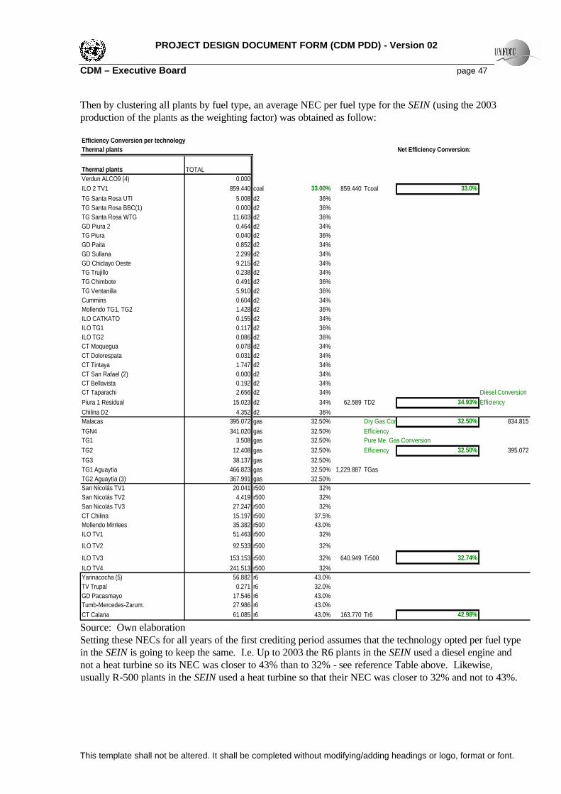
PROJECT DESIGN DOCUMENT FORM (CDM PDD) - Version 02 CDM – Executive Board page 47
This template shall not be altered. It shall be completed without modifying/adding headings or logo, format or font.
Then by clustering all plants by fuel type, an average NEC per fuel type for the SEIN (using the 2003 production of the plants as the weighting factor) was obtained as follow: Efficiency Conversion per technologyThermal plants Net Efficiency Conversion:
Thermal plants TOTALVerdun ALCO9 (4) 0.000ILO 2 TV1 859.440 coal 33.00% 859.440 Tcoal 33.0%TG Santa Rosa UTI 5.008 d2 36%TG Santa Rosa BBC(1) 0.000 d2 36%TG Santa Rosa WTG 11.603 d2 36%GD Piura 2 0.464 d2 34%TG Piura 0.040 d2 36%GD Paita 0.852 d2 34%GD Sullana 2.299 d2 34%GD Chiclayo Oeste 9.215 d2 34%TG Trujillo 0.238 d2 34%TG Chimbote 0.491 d2 36%TG Ventanilla 5.910 d2 36%Cummins 0.604 d2 34%Mollendo TG1, TG2 1.428 d2 36%ILO CATKATO 0.155 d2 34%ILO TG1 0.117 d2 36%ILO TG2 0.086 d2 36%CT Moquegua 0.078 d2 34%CT Dolorespata 0.031 d2 34%CT Tintaya 1.747 d2 34%CT San Rafael (2) 0.000 d2 34%CT Bellavista 0.192 d2 34%CT Taparachi 2.656 d2 34% Diesel ConversionPiura 1 Residual 15.023 d2 34% 62.589 TD2 34.93% EfficiencyChilina D2 4.352 d2 36%Malacas 395.072 gas 32.50% Dry Gas Conversion 32.50% 834.815TGN4 341.020 gas 32.50% EfficiencyTG1 3.508 gas 32.50% Pure Me. Gas ConversionTG2 12.408 gas 32.50% Efficiency 32.50% 395.072TG3 38.137 gas 32.50%TG1 Aguaytía 466.823 gas 32.50% 1,229.887 TGasTG2 Aguaytía (3) 367.991 gas 32.50%San Nicolás TV1 20.041 r500 32%San Nicolás TV2 4.419 r500 32%San Nicolás TV3 27.247 r500 32%CT Chilina 15.197 r500 37.5%Mollendo Mirrlees 35.382 r500 43.0%ILO TV1 51.463 r500 32%
ILO TV2 92.533 r500 32%
ILO TV3 153.153 r500 32% 640.949 Tr500 32.74%ILO TV4 241.513 r500 32%Yarinacocha (5) 56.882 r6 43.0%TV Trupal 0.271 r6 32.0%GD Pacasmayo 17.546 r6 43.0%Tumb-Mercedes-Zarum. 27.986 r6 43.0%CT Calana 61.085 r6 43.0% 163.770 Tr6 42.98% Source: Own elaboration Setting these NECs for all years of the first crediting period assumes that the technology opted per fuel type in the SEIN is going to keep the same. I.e. Up to 2003 the R6 plants in the SEIN used a diesel engine and not a heat turbine so its NEC was closer to 43% than to 32% - see reference Table above. Likewise, usually R-500 plants in the SEIN used a heat turbine so that their NEC was closer to 32% and not to 43%.
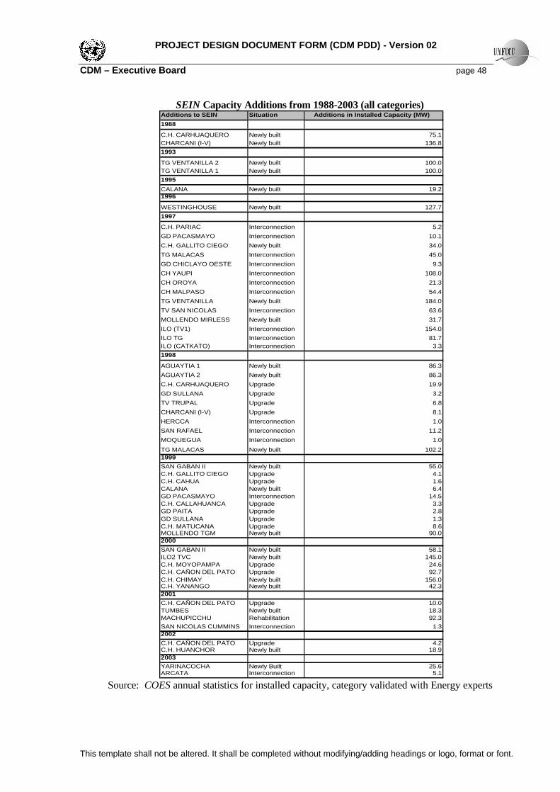
PROJECT DESIGN DOCUMENT FORM (CDM PDD) - Version 02 CDM – Executive Board page 48
This template shall not be altered. It shall be completed without modifying/adding headings or logo, format or font.
SEIN Capacity Additions from 1988-2003 (all categories)
Additions to SEIN Situation Additions in Installed Capacity (MW)1988
C.H. CARHUAQUERO Newly built 75.1CHARCANI (I-V) Newly built 136.81993
TG VENTANILLA 2 Newly built 100.0TG VENTANILLA 1 Newly built 100.01995CALANA Newly built 19.21996TG STA. ROSA WESTINGHOUSE Newly built 127.71997
C.H. PARIAC Interconnection 5.2GD PACASMAYO Interconnection 10.1C.H. GALLITO CIEGO Newly built 34.0TG MALACAS Interconnection 45.0GD CHICLAYO OESTE Interconnection 9.3CH YAUPI Interconnection 108.0CH OROYA Interconnection 21.3CH MALPASO Interconnection 54.4TG VENTANILLA Newly built 184.0TV SAN NICOLAS Interconnection 63.6MOLLENDO MIRLESS Newly built 31.7ILO (TV1) Interconnection 154.0ILO TG Interconnection 81.7ILO (CATKATO) Interconnection 3.31998
AGUAYTIA 1 Newly built 86.3AGUAYTIA 2 Newly built 86.3C.H. CARHUAQUERO Upgrade 19.9GD SULLANA Upgrade 3.2TV TRUPAL Upgrade 6.8CHARCANI (I-V) Upgrade 8.1HERCCA Interconnection 1.0SAN RAFAEL Interconnection 11.2MOQUEGUA Interconnection 1.0TG MALACAS Newly built 102.21999SAN GABAN II Newly built 55.0C.H. GALLITO CIEGO Upgrade 4.1C.H. CAHUA Upgrade 1.6CALANA Newly built 6.4GD PACASMAYO Interconnection 14.5C.H. CALLAHUANCA Upgrade 3.3GD PAITA Upgrade 2.8GD SULLANA Upgrade 1.3C.H. MATUCANA Upgrade 8.6MOLLENDO TGM Newly built 90.02000SAN GABAN II Newly built 58.1ILO2 TVC Newly built 145.0C.H. MOYOPAMPA Upgrade 24.6C.H. CAÑON DEL PATO Upgrade 92.7C.H. CHIMAY Newly built 156.0C.H. YANANGO Newly built 42.32001C.H. CAÑON DEL PATO Upgrade 10.0TUMBES Newly built 18.3MACHUPICCHU Rehabilitation 92.3SAN NICOLAS CUMMINS Interconnection 1.32002C.H. CAÑON DEL PATO Upgrade 4.2C.H. HUANCHOR Newly built 18.92003YARINACOCHA Newly Built 25.6ARCATA Interconnection 5.1
Source: COES annual statistics for installed capacity, category validated with Energy experts

PROJECT DESIGN DOCUMENT FORM (CDM PDD) - Version 02 CDM – Executive Board page 49
This template shall not be altered. It shall be completed without modifying/adding headings or logo, format or font.
Installed capacity per power plant of the SEIN, as of December 31st, for 1996-2003 1996 1997
PLANT INSTALLED CAPACITY (MW) PLANT INSTALLED CAPACITY (MW)AGUAYTIA ENERGY S.A. AGUAYTIA ENERGY S.A.
CAHUA S.A. CAHUA S.A.C.H. CAHUA 41.5 C.H. CAHUA 41.5
C.H. PARIAC 5.2CNP ENERGIA S.A. CNP ENERGIA S.A.
GD PACASMAYO 10.1C.H. GALLITO CIEGO 34.0
EDEGEL EDEGELC.H. HUINCO 258.4 C.H. HUINCO 258.4C.H. MATUCANA 120.0 C.H. MATUCANA 120.0C.H. CALLAHUANCA 71.0 C.H. CALLAHUANCA 71.0C.H. MOYOPAMPA 63.6 64.7 C.H. MOYOPAMPA 63.0C.H. HUAMPANI 31.4 C.H. HUAMPANI 31.4
TG STA. ROSA WESTINGHOUSE 127.7 TG STA. ROSA WESTINGHOUSE 127.7TG STA. ROSA UTI 109.8 TG STA. ROSA UTI 109.8TG STA. ROSA BBC 52.2 TG STA. ROSA BBC 52.2EEPSA EEPSA
45 TG MALACAS 36.0
EGENOR S.A. EGENOR S.A.C.H. CAÑON DEL PATO 153.9 C.H. CAÑON DEL PATO 153.9C.H. CARHUAQUERO 75.1 C.H. CARHUAQUERO 75.1TG CHIMBOTE 63.4 TG CHIMBOTE 63.4TG PIURA 24.3 TG PIURA 24.3TG TRUJILLO 22.8 TG TRUJILLO 22.8GD PIURA 26.3 GD PIURA 26.3GD CHICLAYO 17.3 26.61 GD CHICLAYO OESTE 21.0
CHICLAYO NORTE 7.5GD PAITA 8.3 GD PAITA 8.3GD SULLANA 8.0 GD SULLANA 8.0TV TRUPAL 12.0 TV TRUPAL 12.0
ELECTROANDES S.A.CH YAUPI 108.0CH OROYA 9.0
12.28 CH PACHACHACA 12.0CH MALPASO 54.4
ELECTROPERU ELECTROPERUC.H. MANTARO 798.0 C.H. MANTARO 798.0C.H. RESTITUCION 210.4 C.H. RESTITUCION 210.4
ETEVENSA ETEVENSA
TG VENTANILLA 200.0 TG VENTANILLA 519.2
SHOUGESA
63.6 TV SAN NICOLAS 62.5
EGASA EGASACHARCANI (I-V) 165.16 CHARCANI I 168.82
31.7 MOLLENDO MIRLESS 32.09
CHILINA TV 22 CHILINA TV 22CHILINA CC 20 CHILINA CC 20CHILINA SULZER 10.4 CHILINA SULZER 10.4EGEMSA EGEMSA
MACHUPICCHU 109.90 MACHUPICCHU 109.90DOLORESPATA 15.62 DOLORESPATA 15.62
BELLAVISTA 8.60 BELLAVISTA 7.83
TAPARACHI 6.60 TAPARACHI 7.80EGESUR EGESURARICOTA I, II 35.70 ARICOTA I, II 35.70CALANA 19.20 CALANA 19.20
PARA 2.50 PARA 2.50ENERSUR
154 ILO (TV1) 176.00ILO TG 81.69ILO (CATKATO) 3.30
Source: COES

PROJECT DESIGN DOCUMENT FORM (CDM PDD) - Version 02 CDM – Executive Board page 50
This template shall not be altered. It shall be completed without modifying/adding headings or logo, format or font.
Continue: Installed capacity per power plant of the SEIN, as of December 31st, for 1996-2003 1998 1999
PLANT INSTALLED CAPACITY (MW) PLANT INSTALLED CAPACITY (MW)AGUAYTIA ENERGY S.A. AGUAYTIA ENERGY S.A.AGUAYTIA 1 101.3 AGUAYTIA 1 86.29AGUAYTIA 2 101.3 AGUAYTIA 2 86.29CAHUA S.A. CAHUA S.A.C.H. CAHUA 41.5 C.H. CAHUA 43.1C.H. PARIAC 5.2 C.H. PARIAC 5.2CNP ENERGIA S.A. CNP ENERGIA S.A.GD PACASMAYO 10.1 24.62 GD PACASMAYO 24.8C.H. GALLITO CIEGO 34.0 C.H. GALLITO CIEGO 38.1
EDEGEL EDEGELC.H. HUINCO 258.4 C.H. HUINCO 258.4C.H. MATUCANA 120.0 C.H. MATUCANA 128.6C.H. CALLAHUANCA 71.0 C.H. CALLAHUANCA 74.3C.H. MOYOPAMPA 63.0 C.H. MOYOPAMPA 64.7C.H. HUAMPANI 31.4 C.H. HUAMPANI 30.2
TG STA. ROSA WESTINGHOUSE 127.7 TG STA. ROSA WESTINGHOUSE 127.7TG STA. ROSA UTI 109.8 TG STA. ROSA UTI 109.8TG STA. ROSA BBC 52.2 TG STA. ROSA BBC 52.2EEPSA EEPSATG MALACAS 147.2 TG MALACAS 147.2VERDUN 2.2 VERDUN 2.3EGENOR S.A. EGENOR S.A.C.H. CAÑON DEL PATO 153.9 C.H. CAÑON DEL PATO 153.9C.H. CARHUAQUERO 95.0 C.H. CARHUAQUERO 95TG CHIMBOTE 63.4 TG CHIMBOTE 63.8TG PIURA 24.3 TG PIURA 24.3TG TRUJILLO 22.8 TG TRUJILLO 22.8GD PIURA 26.3 GD PIURA 26.3GD CHICLAYO OESTE 25.3 GD CHICLAYO OESTE 26.61
GD PAITA 8.3 GD PAITA 11.1GD SULLANA 11.2 GD SULLANA 12.5TV TRUPAL 18.8 TV TRUPAL 15ELECTROANDES S.A. ELECTROANDES S.A.CH YAUPI 108.0 CH YAUPI 108CH OROYA 9.0 CH OROYA 9CH PACHACHACA 12.0 CH PACHACHACA 12.3CH MALPASO 54.4 CH MALPASO 54.4ELECTROPERU ELECTROPERUC.H. MANTARO 798.0 C.H. MANTARO 798C.H. RESTITUCION 210.4 C.H. RESTITUCION 210.4
ETEVENSA ETEVENSA
TG VENTANILLA 561.6 TG VENTANILLA 549.3
SHOUGESA SHOUGESA
TV SAN NICOLAS 62.50 TV SAN NICOLAS 63.586
EGASA EGASACHARCANI I 176.89 CHARCANI 176.89MOLLENDO MIRLESS 31.7 MOLLENDO MIRLESS 31.71
MOLLENDO TGM 90CHILINA TV 22 CHILINA TV 22CHILINA CC 20 CHILINA CC 20CHILINA SULZER 10.4 CHILINA SULZER 10.4EGEMSA EGEMSAHERCCA 1.02 HERCA 1.02
DOLORESPATA 15.62 DOLORESPATA 15.62SAN GABANSAN GABAN II 55
TINTAYA 17.96 TINTAYA 17.96BELLAVISTA 8.60 BELLAVISTA 8.6SAN RAFAEL 11.16 SAN RAFAEL 11.16TAPARACHI 8.80 TAPARACHI 8.8EGESUR EGESURARICOTA I 35.70 ARICOTA 35.7CALANA 19.20 CALANA 25.6MOQUEGUA 1.00 MOQUEGUA 1PARA 2.50 PARA 2.5ENERSUR ENERSUR ILO (TV1) 176.00 ILO 1 176ILO TG 79.29 ILO 1 TG 79.29ILO (CATKATO) 3.30 ILO 1 CATKATO 3.3
Source: COES

PROJECT DESIGN DOCUMENT FORM (CDM PDD) - Version 02 CDM – Executive Board page 51
This template shall not be altered. It shall be completed without modifying/adding headings or logo, format or font.
Continue: Installed capacity per power plant of the SEIN, as of December 31st, for 1996-2003 2000 2001
PLANT INSTALLED CAPACITY (MW) PLANT INSTALLED CAPACITY (MW)AGUAYTIA ENERGY S.A. AGUAYTIA ENERGY S.A.AGUAYTIA 1 86.294 AGUAYTIA 1 86.294AGUAYTIA 2 86.294 AGUAYTIA 2 86.294CAHUA S.A. CAHUA S.A.C.H. CAHUA 43.6 C.H. CAHUA 43.6C.H. PARIAC 5.216 C.H. PARIAC 5.216CNP ENERGIA S.A. CNP ENERGIA S.A.GD PACASMAYO 24.562 GD PACASMAYO 24.591C.H. GALLITO CIEGO 38.147 C.H. GALLITO CIEGO 38.147
EDEGEL EDEGELC.H. HUINCO 258.4 C.H. HUINCO 258.4C.H. MATUCANA 128.578 C.H. MATUCANA 128.578C.H. CALLAHUANCA 75.059 C.H. CALLAHUANCA 75.059C.H. MOYOPAMPA 89.25 C.H. MOYOPAMPA 89.25C.H. HUAMPANI 31.36 C.H. HUAMPANI 31.36C.H. YANANGO 42.3 C.H. YANANGO 42.3C.H. CHIMAY 156 C.H. CHIMAY 156
TG STA. ROSA WESTINGHOUSE 127.7 TG STA. ROSA WESTINGHOUSE 127.7TG STA. ROSA UTI 109.8 TG STA. ROSA UTI 109.8TG STA. ROSA BBC 52.2 TG STA. ROSA BBC 52.2EEPSA EEPSATG MALACAS 141.296 TG MALACAS 173.2VERDUN 2.319 VERDUN 2.319EGENOR S.A. EGENOR S.A.C.H. CAÑON DEL PATO 246.582 C.H. CAÑON DEL PATO 256.55C.H. CARHUAQUERO 95.02 C.H. CARHUAQUERO 95.02TG CHIMBOTE 63.833 TG CHIMBOTE 63.833TG PIURA 24.3 TG PIURA 24.3TG TRUJILLO 22.8 TG TRUJILLO 22.8GD PIURA 26.715 GD PIURA 27.277GD CHICLAYO OESTE 26.61 GD CHICLAYO OESTE 26.61
GD PAITA 11.112 GD PAITA 11.112GD SULLANA 12.5 GD SULLANA 12.5TV TRUPAL 15 TV TRUPAL 15ELECTROANDES S.A. ELECTROANDES S.A.CH YAUPI 108 CH YAUPI 108CH OROYA 9 CH OROYA 9CH PACHACHACA 12.282 CH PACHACHACA 12.282CH MALPASO 54.4 CH MALPASO 54.4ELECTROPERU ELECTROPERUC.H. MANTARO 798 C.H. MANTARO 798C.H. RESTITUCION 210.4 C.H. RESTITUCION 210.4
TUMBES 18.339
ETEVENSA ETEVENSA
TG VENTANILLA 549.316 TG VENTANILLA 384
SHOUGESA SHOUGESA
TV SAN NICOLAS 63.586 TV SAN NICOLAS 63.586SAN NICOLAS CUMMINS 1.25
EGASA EGASACHARCANI 176.89 CHARCANI 176.89MOLLENDO MIRLESS 31.71 MOLLENDO MIRLESS 31.71MOLLENDO TGM 90 MOLLENDO TGM 90CHILINA TV 18 CHILINA TV 18CHILINA CC 20 CHILINA CC 20CHILINA SULZER 10.4 CHILINA SULZER 10.4EGEMSA EGEMSAHERCA 1.02 HERCA 1.02
MACHUPICCHU 92.25DOLORESPATA 15.62 DOLORESPATA 15.62SAN GABAN SAN GABANSAN GABAN II 110 SAN GABAN II 112.9TINTAYA 17.96 TINTAYA 17.96BELLAVISTA 8.6 BELLAVISTA 8.6SAN RAFAEL 11.16 SAN RAFAEL 11.16TAPARACHI 8.8 TAPARACHI 8.8EGESUR EGESURARICOTA 35.7 ARICOTA 35.7CALANA 25.6 CALANA 25.6MOQUEGUA 1 MOQUEGUA 1
ENERSUR ENERSURILO 1 154 ILO 1 154ILO 1 TG 81.69 ILO 1 TG 81.69ILO 1 CATKATO 3.3 ILO 1 CATKATO 3.3ILO2 TVC 135 ILO2 TVC 145
Source: COES

PROJECT DESIGN DOCUMENT FORM (CDM PDD) - Version 02 CDM – Executive Board page 52
This template shall not be altered. It shall be completed without modifying/adding headings or logo, format or font.
Continue: Installed capacity per power plant of the SEIN, as of December 31st, for 1996-2003 2002 2003
PLANT INSTALLED CAPACITY (MW) PLANT INSTALLED CAPACITY (MW)AGUAYTIA ENERGY S.A. TERMOSELVAAGUAYTIA 1 86.294 AGUAYTIA 1 86.294AGUAYTIA 2 86.294 AGUAYTIA 2 86.294CAHUA S.A. CAHUA S.A.C.H. CAHUA 43.6 CAHUA 43.600C.H. PARIAC 5.216 PARIAC 5.216CNP ENERGIA S.A. E. PACASMAYOGD PACASMAYO 24.545 PACASMAYO 24.617C.H. GALLITO CIEGO 38.147 GALLITO CIEGO 38.147
ARCATA 5.098
EDEGEL EDEGELC.H. HUINCO 258.4 HUINCO 258.400C.H. MATUCANA 128.578 MATUCANA 128.578C.H. CALLAHUANCA 75.059 CALLAHUANCA 75.059C.H. MOYOPAMPA 89.25 MOYOPAMPA 89.250C.H. HUAMPANI 31.6 HUAMPANI 31.360C.H. YANANGO 42.3 YANANGO 42.300C.H. CHIMAY 156 CHIMAY 156.000C.H. HUANCHOR 18.86 HUANCHOR 18.860TG STA. ROSA WESTINGHOUSE 127.7 SANTA ROSA WTG 127.700TG STA. ROSA UTI 109.8 SANTA ROSA UTI 109.800TG STA. ROSA BBC 52.2EEPSA EEPSATG MALACAS 173.2 ##### MALACAS 173.2VERDUN 1.001EGENOR S.A. EGENORC.H. CAÑON DEL PATO 260.73 CAÑON DEL PATO 260.730C.H. CARHUAQUERO 95.02 CARHUAQUERO 95.020TG CHIMBOTE 63.833 CHIMBOTE 63.833TG PIURA 24.3 TG PIURA 24.300TG TRUJILLO 22.8 TRUJILLO 22.800GD PIURA 27.85 PIURA 27.850GD CHICLAYO OESTE 26.61 CHICLAYO OESTE 26.610
GD PAITA 11.12 PAITA 11.112GD SULLANA 12.5 SULLANA 12.500TV TRUPAL 15 TRUPAL 15.000ELECTROANDES S.A. ELECTROANDESCH YAUPI 108 YAUPI 108.000CH OROYA 9 OROYA 9.000CH PACHACHACA 12.282 PACHACHACA 12.282CH MALPASO 54.4 MALPASO 54.400ELECTROPERU ELECTROPERUC.H. MANTARO 798 COMPLEJO MANTARO - MANTARO 798.000C.H. RESTITUCION 210.4 COMPLEJO MANTARO-RESTITUCION 210.400TUMBES 18.339 18.34 TUMBES 18.244
YARINACOCHA 25.600
ETEVENSA ETEVENSA
TG VENTANILLA 384 VENTANILLA 384
SHOUGESA SHOUGESA
TV SAN NICOLAS 63.586 SAN NICOLAS TV 1-2-3 63.586SAN NICOLAS CUMMINS 1.25 SAN NICOLAS CUMNIS 1.25
EGASA EGASACHARCANI 176.89 CHARCANI 176.890MOLLENDO MIRLESS 31.71 MOLLENDO MIRLESS 31.710MOLLENDO TGM 90 MOLLENDO TGM 90.000CHILINA TV 18 CHILINA TV 18.000CHILINA CC 20 CHILINA C.C 20.000CHILINA SULZER 10.4 CHILINA SULZER 10.400EGEMSA EGEMSAHERCA 1.02 HERCA 1.020MACHUPICCHU 92.25 MACHUPICCHU 92.250DOLORESPATA 15.62 DOLORESPATA 15.620SAN GABAN SAN GABANSAN GABAN II 112.9 SAN GABAN II 113.098TINTAYA 17.96 TINTAYA 17.960BELLAVISTA 8.6 BELLAVISTA 8.600SAN RAFAEL 11.16TAPARACHI 8.8 TAPARACHI 8.800EGESUR EGESURARICOTA 35.7 ARICOTA 35.7CALANA 25.6 CALANA 25.6MOQUEGUA 1 MOQUEGUA 1
ENERSUR ENERSURILO 1 154 ILO 1 TV 154.000ILO 1 TG 81.69 ILO 1 TG 81.690ILO 1 CATKATO 3.3 ILO 1 CATKATO 3.300
ILO2 TVC 145 ILO 2 TVC1 145.000 Source: COES

PROJECT DESIGN DOCUMENT FORM (CDM PDD) - Version 02 CDM – Executive Board page 53
This template shall not be altered. It shall be completed without modifying/adding headings or logo, format or font.
Detail of LRMC variables In detail, Ii: Sum of Equivalent Annual Costs of the New Capacity Investments ($ millions) for year i. Parameters considered for each Annuity were:
14% discount rate; expected life of thermal plants = 30 years; expected life of hydroelectric plants=40 years; depreciation method: sinking fund The Investment Cost considers: a) Additional generation plants that start operations in years 2007-2017. Plants to be built were assumed to use the most attractive technology for generation available in the market, natural gas. Their size and technological characteristics were determined by the WASP Program (Wien Automatic System Planning Package) out of the following options given:
Alternatives Technologies considered for the WASP Optimization Model Alternative Unit name Observations
GT 100 MW G100 O.C GT 100 MW NG Outside Lima - Camisea NG
GT 150 MW G150 O.C GT 150 MW NG Outside Lima - Camisea NG
CC 2 GT 100+1 HT 100 CC300 CC 300 MW -NG 2 GT of 100 MW - Camisea NG 1 HT of 100 MW - Camisea NG
CC 2 GT 150 + 1 HT 150 CC450 CC 450 MW –NG 2 GT of 150 MW - Camisea NG 1 HTof 150 MW - Camisea NG
Source: Own elaboration Other fossil fuel technologies were not given as options because their levalized costs are higher, as shows the graph below54:
Load Factors
Source: Own elaboration 54 Only the large Hydro Project Platanal (270MW) shows a lower Levelized Cost- because of its economies of scale, but this project is not considered as an alternative, because its required concession for the land is not likely to be granted anytime soon
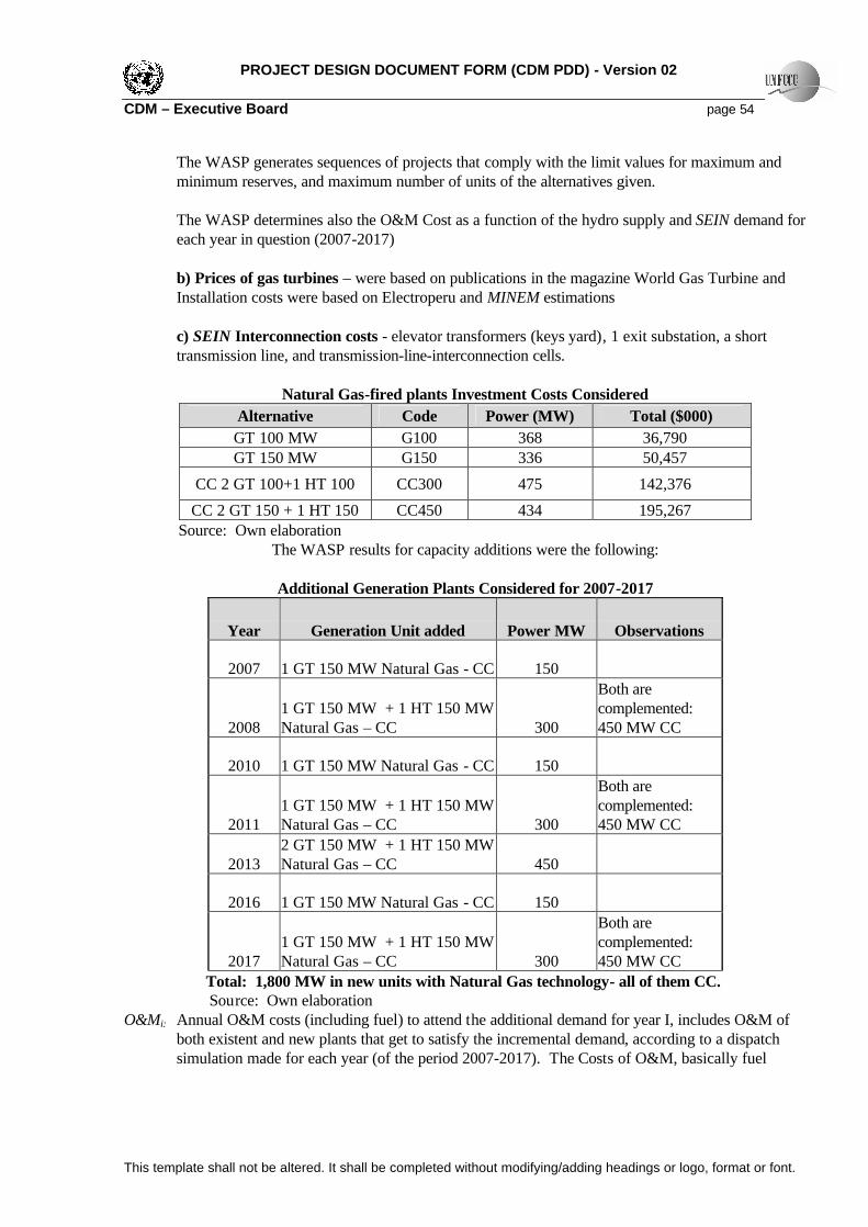
PROJECT DESIGN DOCUMENT FORM (CDM PDD) - Version 02 CDM – Executive Board page 54
This template shall not be altered. It shall be completed without modifying/adding headings or logo, format or font.
The WASP generates sequences of projects that comply with the limit values for maximum and minimum reserves, and maximum number of units of the alternatives given.
The WASP determines also the O&M Cost as a function of the hydro supply and SEIN demand for each year in question (2007-2017)
b) Prices of gas turbines – were based on publications in the magazine World Gas Turbine and Installation costs were based on Electroperu and MINEM estimations c) SEIN Interconnection costs - elevator transformers (keys yard), 1 exit substation, a short transmission line, and transmission-line-interconnection cells.
Natural Gas-fired plants Investment Costs Considered
Alternative Code Power (MW) Total ($000) GT 100 MW G100 368 36,790 GT 150 MW G150 336 50,457
CC 2 GT 100+1 HT 100 CC300 475 142,376 CC 2 GT 150 + 1 HT 150 CC450 434 195,267
Source: Own elaboration The WASP results for capacity additions were the following:
Additional Generation Plants Considered for 2007-2017
Year Generation Unit added Power MW Observations
2007 1 GT 150 MW Natural Gas - CC 150
2008 1 GT 150 MW + 1 HT 150 MW Natural Gas – CC 300
Both are complemented: 450 MW CC
2010 1 GT 150 MW Natural Gas - CC 150
2011 1 GT 150 MW + 1 HT 150 MW Natural Gas – CC 300
Both are complemented: 450 MW CC
2013 2 GT 150 MW + 1 HT 150 MW Natural Gas – CC 450
2016 1 GT 150 MW Natural Gas - CC 150
2017 1 GT 150 MW + 1 HT 150 MW Natural Gas – CC 300
Both are complemented: 450 MW CC
Total: 1,800 MW in new units with Natural Gas technology- all of them CC. Source: Own elaboration O&Mi: Annual O&M costs (including fuel) to attend the additional demand for year I, includes O&M of
both existent and new plants that get to satisfy the incremental demand, according to a dispatch simulation made for each year (of the period 2007-2017). The Costs of O&M, basically fuel

PROJECT DESIGN DOCUMENT FORM (CDM PDD) - Version 02 CDM – Executive Board page 55
This template shall not be altered. It shall be completed without modifying/adding headings or logo, format or font.
costs, were not calculated in a direct manner with a load factor, but instead, they were the result of a Dispatch Simulation. The dispatch simulation considered monthly load factor variations and monthly hydro supply variations. The dispatch simulation also considered temporal shutting down of plants’ operations for maintenance purposes. Thus, in each month of the period in question, the production of fossil fuel fired plants is a function of the hydroelectric supply (function of the hydrological projected conditions) and the demand.
O&M Composition: a) Variable Costs of Fuel (US$/MWh) Fuel price (c$/106 Kcal) and specific caloric consumption (Kcal/KWh). The latter was obtained from the specific fuel consumption (g/kWh) and the caloric value of the fuel in question (Kcal/Kg) – the specific caloric consumption at minimum charge and the incremental consumption were obtained from statistics of engines’ power and performance trials recorded by COES
The Fuel prices55 taken were the 2002’s, because after that year the prices are biased by the War with Irak:
Liquid-Fuel Prices used for the LRMC Calculation
Plant Fuel Type Soles56/Gln $/Gln $/Barrel $/Ton Kg/Gln (density)
D2 2.94 0.84 35.28 258.62 3.248 R6 2.43 0.69 29.16 192.22 3.612 Callao
R500 2.38 0.68 28.56 185.03 3.675 D2 2.93 0.84 35.16 257.74 3.248 Mollendo R500 2.42 0.69 29.04 188.14 3.675 D2 2.96 0.85 35.52 260.38 3.248 Ilo R6 2.46 0.70 29.52 194.59 3.612
Source: Own elaboration Non-Liquid Fuel Prices used for the LRMC Calculation
Coal Price ILO2 is the only coal-fired thermal plant in Peru. It uses imported coal, which price is a function of standard coal with superior calorific power of 6,240 Kcal/Kg. The coal price assigned to this plant by COES and OSINERG is $38.9/MT
Natural Gas Price
Malacas TG-4 and Aguaytia Gas Prices considered were those of the 2003 projection made by OSINERG, which was $2.199/MMBTU - the price of the Camisea Gas is much lower ($1/MMBTU for the electric sector)
Source: Own elaboration
b) Non-Fuel Variable Costs These costs were taken from OSINERG reports. These cost comprise Variable Costs of additives, lubricants, spares, materials and other maintenance expenses - all expressed in US$/MWh.
55 Do not include Selective Consumption Tax (ISC), because ISC is exonerated for electricity generators. V.A.T is not included because this is recovered by the generating company as a fiscal credit when it sells its energy produced 56 Exchange rate: 3.5 Soles/$

PROJECT DESIGN DOCUMENT FORM (CDM PDD) - Version 02 CDM – Executive Board page 56
This template shall not be altered. It shall be completed without modifying/adding headings or logo, format or font.
c) O&M Fixed Costs These costs were taken from MINEM reports . These costs comprise fixed costs of payroll expenses for employees in charge of the plant operation, plant supervision, plant maintenance, plant security and other general expenses-all expressed in US$/KW- month.
O&M for new plants
Units Code Max. Power
Min Power
Specific Caloric
Consumption Fuel Cost O&M Costs
Max Min Incremental Min Domestic Fixed Cost V. Cost
KW Kcal/kWh c$/10^6Kcal $/KW-month $/MWh
GT 100 MW G100 100 25 2300 3340 856.3 1 4 GT 150 MW G150 150 38 1960 3424 856.3 0.7 3
CC 2 GT 100 + 1 HT 100
C300 300 150 1400 2013 856.3 1.4 2.4
CC 2 GT 150 + 1 HT 150
C450 450 225 1250 1851 856.3 0.98 1.8
Source: Own elaboration NSEi: Non-served energy in year I (assumed to be zero, because this effect was incorporated in the Di
variable) Di: Additional Demand in year i
Projections for 2007-2017 were based on OSINERG projections from 2003-2007 and the following assumptions: a) Both GDP and population growth will maintain their average growth of the 2003-2007 period. b) Price of electricity generation will maintain the 2003-2007 OSINERG Projection c) Energy losses in distribution and transmission will be kept at levels projected for 2007 by OSINERG.
d) Demand will be equal to OSINERG projection for the 2007, and from 2008 to 2017, the demand from mining projects will increase at 5% annually.
e) The future interconnection with Ecuador will cause exports from Peru to Ecuador only . The demand of Ecuador is added to the demand of Peru in wet months, from December to April up (147 GWh) for all the period 2007-2017

PROJECT DESIGN DOCUMENT FORM (CDM PDD) - Version 02 CDM – Executive Board page 57
This template shall not be altered. It shall be completed without modifying/adding headings or logo, format or font.
The results for the projected demand are:
SEIN Demand Projection
Year Power MW Energy GWh Power Growth Rate Energy Load Factor
2007 3480 24062 3.22% 3.63% 78.9% 2008 3603 24935 3.55% 3.63% 79.0% 2009 3731 25789 3.55% 3.42% 78.9% 2010 3864 26681 3.55% 3.46% 78.8% 2011 3999 27588 3.51% 3.40% 78.7% 2012 4143 28549 3.58% 3.48% 78.7% 2013 4291 29539 3.59% 3.47% 78.6% 2014 4445 30563 3.57% 3.47% 78.5% 2015 4602 31618 3.55% 3.45% 78.4% 2016 4766 32710 3.55% 3.45% 78.4% 2017 4935 33839 3.55% 3.45% 78.3%
Source: Own elaboration N: Number of years in the period of analysis (i = 1, ....,n)
Period = 2007-2017
Annex 4
MONITORING PLAN

PROJECT DESIGN DOCUMENT FORM (CDM PDD) - Version 02 CDM – Executive Board page 58
This template shall not be altered. It shall be completed without modifying/adding headings or logo, format or font.
Monitoring Plan
For
Poechos I
First Crediting Period (2004-2011)
November 2004
Prepared by
World Bank Carbon Finance Business

PROJECT DESIGN DOCUMENT FORM (CDM PDD) - Version 02 CDM – Executive Board page 59
This template shall not be altered. It shall be completed without modifying/adding headings or logo, format or font.
GLOSSARY
APFR: Annual Plant Fuel Requirement (TJ) Baseline Emissions: Product of EFy times EGy BLS: Latest Baseline Study BM: Build Margin Emission Factor CDM: Clean Development Mechanism CERs: Certified Emission Reductions CM: Combined Margin Emission Factor COEF: tCO2/MWh COES: Committee of Economical Operation of the SEIN (Dispatch Center) DDA-OM: Dispatch Data Analysis Operating Margin Emission Factor EFy: Baseline Emission Factor (tCO2/MWh) EGy: The Project’s annual generation (MWh) ENOSA: Electronoroeste S.A (The Project Final Client) ERPA: Emissions Reductions Purchase Agreement ERCP: Emissions Reductions Calculation Procedure ERs: Green House Gases Emissions Reductions GHG: Green House Gases HP: Hydropower plant (s) Merit Order: Grid Dispatch Weekly Merit Order Monthly Merit Order: Average of Four Weekly Grid Dispatch Merit Orders MP: Monitoring Plan NCDMF: Netherlands Clean Development Mechanism Facility NEC: Net Efficiency Conversion OM: Operating Margin Emission Factor Project Staff: Team or person assigned and trained to perform the ERCP SEIN: National Electric Grid The Operator: SINERSA (The Project Operator) TP: Thermal plant (s) fossil fuel-fired plants

PROJECT DESIGN DOCUMENT FORM (CDM PDD) - Version 02 CDM – Executive Board page 60
This template shall not be altered. It shall be completed without modifying/adding headings or logo, format or font.
TABLE OF CONTENTS
I. Background information II. Purpose of the Monitoring Plan III. Use of the Monitoring Plan by the Operator IV. Organizational, Operational and Monitoring Obligations
A. Obligations of the Operator B. Estimated Anthropogenic Emissions for The Project C. Emissions Reductions Calculation Procedure and Required Spreadsheets
V. Sustainable Development Monitoring Plan
A. Environmental Sustainability: Impact on Local Population B. Socio-Economic Sustainability
VI. Management and Operational Systems Monitoring Plan
A. Purpose B. Data Handling C. Quality Assurance D. Reporting E. Training F. Preparation for Operation
VII. Auditing and Verification Procedures
A. Audit and Verification Objectives B. The NCDMF Audit and Verification Regime C. Auditing Criteria and Needs D. Auditing and Verification Process E. Roles and Responsibilities
VIII. Annexes.

PROJECT DESIGN DOCUMENT FORM (CDM PDD) - Version 02 CDM – Executive Board page 61
This template shall not be altered. It shall be completed without modifying/adding headings or logo, format or font.
I. Background Information The baseline methodology and monitoring methodology for Poechos I, are in accordance with the approved consolidated baseline methodology (ACM0002): Consolidated baseline methodology for zero-emissions grid-connected electricity generation from renewable sources (”The Methodology”). The Methodology was released in September 3rd, 2004 by the Clean Development Mechanism-Executive Board. Poechos I (“The Project”) installed capacity and projected yearly average generation is as follows:
Project name Installed capacity (MW) Generation (GWh/yr) Poechos I 15.40 58.50
Source: Project Appraisal Document The Project is a hydroelectric power plant located in Peru, in the Northwestern Department of Piura. The Project will displace 31,878 tCO2 (approx.) per year, which account for 223,146 tCO2 (approx.) for the first crediting period (7 years). Methane and Carbon Dioxide are negligible. Therefore there is not need to monitor leakage and it will not be taken into account when calculating ERs. The spatial extent of The Project boundary is the SEIN. The Project is connected to the SEIN through the Sullana Substation, which belongs to Electronoroeste S.A. (ENOSA). The 58.5 GWh (approx.) of electricity generated per year will be sold to ENOSA, a stated-owned enterprise. Until now, neither electricity exports from the SEIN nor electricity imports to the SEIN have taken place. II. Purpose of the Monitoring Plan This report presents the Monitoring Plan (MP) for The Project, which has been considered by The Netherlands Clean Development Mechanism Facility (NCDMF) for ERs purchases in Peru. The MP defines a standard against which the performance in terms of The Project’s ERs will be monitored and verified, in conformance with all relevant requirements of the Clean Development Mechanism (CDM) of The Kyoto Protocol. The MP is part of the ERPA Document and, after its validation, will be an integral part of the contractual agreement between The NCDMF, The Project Developer and The Project Operator (the Operator). As of today, The Project’s Developer is the same enterprise as The Project’s Operator: SINERSA. The CDM defines monitoring as the systematic surveillance of a project’s performance by measuring and recording performance-related indicators relevant to the project activity. Both the Baseline Study (BLS) and the MP are subject to verification procedures. III. Use of the Monitoring Plan by the Operator This report, the MP, identifies key performance indicators of The Project and sets out the procedures for metering, monitoring, calculating and verifying the ERs generated by The Project, annually. Adherence to the instructions in the MP is necessary for the Operator to successfully measure and track the impact of The Project and prepare all data required for the periodic audit and verification process that must be undertaken to confirm the achievement of the corresponding ERs. The MP is thus the basis for the production of ERs and delivery of ERs to The NCDMF. The MP assists the Operator in establishing a credible, transparent, and adequate data measurement, collection, recording and management system to successfully develop and maintain the proper information; required for an audit and for the verification and certification of the achieved ERs and other Project outcomes. Specifically, the MP provides the requirements and instructions for: (i) establishing and maintaining the appropriate monitoring system including spreadsheets for the calculation of ERs, (ii) checking whether The Project meets key sustainable development indicators, (iii) implementing the

PROJECT DESIGN DOCUMENT FORM (CDM PDD) - Version 02 CDM – Executive Board page 62
This template shall not be altered. It shall be completed without modifying/adding headings or logo, format or font.
necessary measurement and management operations, and (iv) preparing for the requirements of independent third party verifications and audits. The MP ensures environmental integrity and accuracy of crediting ERs by only allowing actual ERs to be accounted for after they have been achieved. The MP must therefore be used throughout the period in which The Project has committed to or desires to sell/track ERs. It must be adopted as a key input into the detailed planning of The Project, and included as one of the operational manuals of The Project. The MP can be updated and adjusted to meet operational requirements - the Verifier approves such modifications during the process of initial or periodic verification. In particular, any shifts in the baseline scenario may lead to such amendments, which may be mandated by the Verifier. Amendments may also be necessary as a consequence of new circumstances that affect the ability to monitor ERs as described here or to accommodate new or modified CDM rules. I.V. Organizational, Operational and Monitoring Obligations A. Obligations of the Operator Monitoring performance of The Project requires the fulfillment of operational data collection and processing obligations from the Operator. The Operator has the primary obligation of ensuring that sufficient and accurate information is available to calculate ERs in a transparent manner and of allowing for a successful verification of accounted ERs. The Operator must gather and process information needed to monitor ERs. It is required that the Operator calculate its ERs based on most recent available information, following The ERs Calculation Procedure (ERCP), presented in this report. All data required for the MP will come from COES and; from The Project’s final client, ENOSA57. Data gathering and processing should be done monthly by the Operator, as follow:
At the end of each month:
COES (Data Provider)
-Report of hourly generation of the SEIN’s units (measurement: 15’ or 30’ 58) -Report of weekly dispatch merit orders for “hours of maximum demand 59”
ENOSA (Data Provider) -Report of The Project hourly generation purchased by ENOSA.
Operator (Data processor)
-Verification of ENOSA’s report of The Project hourly generation – comparison with own records; back up of any claims with receipt of sales -Monthly data filling in all the spreadsheets required, following the ERCP -Monthly report to The NCDMF
Source: Own elaboration The Operator should calculate ERs on the basis of this MP (following the ERCP) for the purpose of claiming ERs credits. It is believed that the MP approach presented here will result in an accurate, yet conservative calculation of ERs. However some uncertainties may lead to a deviation of monitored ERs and the verified ERs, especially errors in the data monitoring and processed system. The Operator is 57 As long as The Project Operator is not an active member of COES; when it is, all data will come from COES 58 Half an hour measurement is still acceptable if total SEIN production calculated with it, does not deviate greatly (i.e. less than 1%) from total SEIN Production calculated with the 15-minute measured data 59 (6pm to 11 pm) to set a standard - weekly merit orders for hours of maximum, minimum and medium demand are similar

PROJECT DESIGN DOCUMENT FORM (CDM PDD) - Version 02 CDM – Executive Board page 63
This template shall not be altered. It shall be completed without modifying/adding headings or logo, format or font.
expected to prevent such errors and the verification audits are expected to uncover any possible errors. The CERs would be granted ex-post verification. B. Estimated Anthropogenic Emissions for The Project: The Methodology stipulates that the Baseline of The Project is the Combined Margin Emission Factor, which is the average of the Operating Margin Emission Factor and the Build Margin Emission Factor. Estimated anthropogenic emissions were calculated for The Project following a 4-step-process: Step 1 – Calculation of the Operating Margin Emission Factor (OM) Step 2 – Calculation of the Build Margin Emission Factor (BM) Step 3 – Calculation of the Baseline Emission Factor (CM) Step 4 – Calculation of The Project’s Emissions Reductions Prior to Validation Step 1 – Calculation of the Operating Margin Emission Factor Out of four options for the OM, the Dispatch Data Analysis Operating Margin Emission Factor (DDA-OM) was taken; as it constitutes the first methodological choice where data is available, according to The Methodology. The formula for the DDA-OM used was provided by The Methodology: EF_OMy Dispatch Data (tCO2/MWh)= E_OMy/EGy E_OMy = Sum of [average tCO2/MWh emitted by plants that fall within top 10% of grid system dispatch each hour of the year “times” The Project generation in MWh each hour of the year] EGy = The Project Generation in the year For this calculation the BLS used the units’ hourly generation of 2003, which was the most recent statistic data available. Because at the time the BLS was completed, The Project hourly generation data for a whole year was inexistent, it was assumed that The Project operated at full capacity and dispatched equally during all hours of the year. Considering this assumption, the variables were defined as follow: -EGy: An “approximation” to MWh generated in 2003 by The Project -It was obtained from multiplying Installed Capacity (MWh) of The Project times 8760. -EGh: An “approximation” to MWh generated in each hour of 2003 -It assumed that The Project produced at its full installed capacity (15.4MWh) each hour. -Fi,n,h: Electricity output in MWh hourly produced in 2003 by each unit of the SEIN that fall within the top 10% of grid dispatch. -COEFi,n60: The tCO2/MWh factors assigned to each unit of the SEIN according to its technology – For hydropower plants the COEF = 0. The information of hourly generation of all SEIN units and their COEF associated was organized in columns, where the position of the columns was sorted according to a “monthly grid dispatch merit order” calculated61. This organization helped to identify the plants that fall within top 10% of grid dispatch each hour of the year. 60 COEFs assigned to each unit of the SEIN can be seen in the ERCP Worksheet #1 61 This was done by a simple average of the four weekly Santa Rosa Equivalent Cost Soles/MWh (merit orders) assigned to each unit of the SEIN, by COES, in a month

PROJECT DESIGN DOCUMENT FORM (CDM PDD) - Version 02 CDM – Executive Board page 64
This template shall not be altered. It shall be completed without modifying/adding headings or logo, format or font.
The BLS’s resulting Dispatch Data Analysis Operating Margin Emission Factor was 0.72614 tCO2/MWh and was obtained from dividing E_OMy by EGy =97,960/134,940
E_OMy: SUM Egh*EF_DDh 97,960 134,904 :EGy EOMy/Egy: Operating Margin DDA_OM 0.72614 :EF_OMy DD (TCO2/MWh)
Source: Own elaboration Step 2 – Calculation of the Build Margin Emission Factor According to the Methodology, the BM is defined as the generation-weighted average emission factor of either the 5 most recent or the most recent 20% of power plants built (in generation), whichever group’s annual generation is greater. Both samples should exclude CDM-Status Plants62. Out of the 2 options for the BM, option 2 was selected; this option does not include in-construction plants in the samples and requires an annual ex-post calculation for the first crediting period. The formula to apply to the selected sample is provided by The Methodology: EF_BMy (tCO2/MWh) = [•I,m Fi,m,y,*COEFi,m] / [•mGENm,y] F=Generation of each plant of the selected sample COEF=tCO2/MWh of each plant of the selected sample; GEN=Generation of each plant of the selected sample In the BLS, any increase in installed capacity in the SEIN was identified and considered only if the increase was made in new units added (No: upgrades, rehabilitations or interconnections of old units). The following list shows the capacity additions (new units’) in the SEIN from 1988 to 2003, and their annual generation. As The Project did not generate yet, the annual generation of the additions taken was the average of their three most recent year’s generations. 62 As of today, The Project is the only CDM-Status Plant of the SEIN

PROJECT DESIGN DOCUMENT FORM (CDM PDD) - Version 02 CDM – Executive Board page 65
This template shall not be altered. It shall be completed without modifying/adding headings or logo, format or font.
Additions to the SEIN (1988-2003)63
Years Techn Addition Install.Cap. 2001 Gen 2002 Gen 2003 Gen Annual GenerationCategory Added (MW) (GWh) (GWh) (GWh) (GWh)
1988C.H. CARHUAQUERO HYDRO Newly built 75.1 469.27 479.41 458.78 469.16CHARCANI (I-V) HYDRO Newly built 136.80 842.17 641.80 660.24 714.741993TG VENTANILLA 2 D2 Newly built 100 2.40 2.45 1.54 2.13TG VENTANILLA 1 D2 Newly built 100 2.40 2.45 1.54 2.131995CALANA R6 Newly built 19.2 33.02 25.72 45.81 34.851996STA. ROSA WESTING D2 Newly built 127.7 9.41 5.61 11.60 8.881997C.H. GALLITO CIEGO HYDRO Newly built 34.0 183.53 149.71 121.79 151.68TG VENTANILLA D2 Newly built 184.0 4.41 4.51 2.83 3.92MOLLENDO MIRLESS R500 Newly built 31.7 10.98 9.53 35.37 18.631998AGUAYTIA 1 GAS Newly built 86.3 230.80 412.26 466.80 369.95AGUAYTIA 2 GAS Newly built 86.3 216.30 332.89 367.97 305.72TG MALACAS PM GAS Newly built 102.2 206.23 181.35 274.30 220.631999SAN GABAN II HYDRO Newly built 55.0 357.38 376.19 356.34 363.30CALANA R6 Newly built 6.4 11.01 8.57 15.27 11.62MOLLENDO TGM D2 Newly built 90.0 0.73 0.86 1.43 1.012000SAN GABAN II HYDRO Newly built 58.1 377.51 397.38 376.41 383.76ILO2 TVC COAL Newly built 145.0 338.78 845.93 859.44 681.38C.H. CHIMAY HYDRO Newly built 156.0 724.76 752.96 825.87 767.86C.H. YANANGO HYDRO Newly built 42.3 214.60 239.13 202.28 218.672001TUMBES R6 Newly built 18.3 22.38 20.73 27.99 24.362002C.H. HUANCHOR HYDRO Newly built 18.9 - 36.86 144.64 144.642003
YARINACOCHA R6 Newly Built 25.6 - - 56.88 144.97
% Inst Cap*TGen
Source: Own elaboration Out of this list, the 5 most recently built plants up to 2003 were: 1)Yarinacocha, 2) Huanchor, 3)Tumbes, 4)Yanango and 5) Chimay, and their comprised annual generation was 1,300.5 GWh. Since the annual generation of the 20% most recently built was greater, 3,860.08 GWh, the latter group was selected for the BM calculation. The 20% most recently built plants in generation comprises the whole list above except for 1988 capacity additions in the SEIN64. The selected sample of Newly Built plants was organized (clustered) by type of fuel and each type of fuel annual electricity generation was transformed back to its fuel consumption caloric value through the Annual Plant Fuel Requirement formula65 and multiplied by C x O66 x 44/12 (mass conversion factor). 63 San Gaban appears twice because increases on its installed capacity were 2 units, the first one was put in operation in 1999 and the second one in 2000 – each unit generation was considered accordingly 64 Exactly, the selected sample’s generation comprised 19.69% (or 20% rounded to the nearest integer) of 2001-2003 average annual generation of the SEIN 65 Fully explained in the ERCP 66 C and O use IPCC-1996 world wide values per fuel type

PROJECT DESIGN DOCUMENT FORM (CDM PDD) - Version 02 CDM – Executive Board page 66
This template shall not be altered. It shall be completed without modifying/adding headings or logo, format or font.
The total tCO2 per fuel type that way obtained was summed up and the result was divided by the total generation (MWh) of the selected sample. Hence a weighted average tCO2/MWh of the selected sample was obtained. The BLS’ resulting BM2 was 0.36371 tCO2/MWh, and was obtained from dividing total tCO2 emitted by the selected sample “by” total gen. of the selected sample.
Technologies in Selected Sample Most Recent Year Gen (GWh) % per technology APFR C O 44/12 CO2 Emissions(tCO2)Coal 681.38 18% 7,433.28 25.80 0.980 3.67 689,124d2 18.06 0% 186.12 20.20 0.990 3.67 13,647r6 215.80 6% 1,807.54 21.10 0.990 3.67 138,445
r500 18.63 0% 204.82 21.10 0.990 3.67 15,688Dry Gas 675.68 18% 7,484.40 15.30 0.995 3.67 417,776
Pure Methane Gas 220.63 6% 2,443.85 14.50 0.995 3.67 129,282Dry Gas CC 0.00 0% 0.00 15.30 0.995 3.67 0
Hydro 2,029.91 53% 0.00 0.00 0.000 0.00 0TOTAL 3,860.08 100% 1,403,961
BM2= 0.36371 tCO2//MWh
Source: Own elaboration Step 3 – Calculation of the Baseline Emission Factor The Baseline Emission Factor was calculated as a combined margin (CM), consisting of the simple average67 of both the resulting OM and the resulting BM. All margins are expressed in tCO2/MWh. CM = 0.5*OM + 0.5*BM CM = 0.5*(0.72614) + 0.5*(0.36371) = 0.54493 tCO2/MWh The BLS’s resulting Baseline Emission Factor was 0.54493 tCO2/MWh. Step 4 – Calculation of The Project’s Emissions Reductions Prior to Validation Because The Project itself does not produce any emission , no leakages entered into the calculation of estimated ERs, and the baseline emissions were estimated to be equal to The Project ERs The estimated ERs per year for The Project were obtained from the following multiplication: Estimated Baseline Emissions = CM* (Estimated Annual Project Generation in MWh) Estimated ERs per year = CM* (Estimated Annual Project Generation in MWh) Estimated ERs per year = 0.54493 tCO2/MWh * 58,500 MWh = 31,878 tCO2 or 31,878 ERs Assuming the 3 most recent years (data used for the BSL calculations) were average years in hydrological conditions. The ERs per year estimated for the first crediting period are: Estimated ERs for the first crediting period = 31,878 tCO2/yr* 7 yrs = 223,146 tCO2 or Estimated ERs68. C. Emissions Reductions Calculation Procedure and Required Spreadsheets The Emissions Reductions Calculation Procedure (ERCP) is the basic instrument for gathering, recording and processing information that will result in the measured ERs. The Operator shall keep The Project ERCP as a manual. The ERCP should contain: i) data gathered from The Project final client: ENOSA69, ii) data gathered from COES information system, and iii) data processed by the Operator. All data processing should be done in Excel. The ERCP is designed for monthly calculation, based on final monthly COES reports and the final client monthly recording. Although it will only be possible to know the ERs at the end of each year (March 31st for The Project), filling data monthly in the required spreadsheets will 67 The default weights (50%,50%) were kept 68 All margins were rounded to the fifth decimal, but the CERs per year was rounded down to the nearest integer 69 When the Project Operator becomes an active member of COES, all data will come from COES

PROJECT DESIGN DOCUMENT FORM (CDM PDD) - Version 02 CDM – Executive Board page 67
This template shall not be altered. It shall be completed without modifying/adding headings or logo, format or font.
provide time to review formulas, minimize errors and have data readily available for the Verifier in any period of the year. There are only 2 required spreadsheets to update with new data: Poechos DDA-OM.xls and Poechos BM2.xls. The names of these files should be kept but should also reflect the date for which the latest adjustment is made. DDA-OM Spreadsheet: This excel file contains all data and formulas necessary to calculate the Dispatch Data Analysis Operating Margin. The data’s year is the year of project generation (April1st-March31st). 14 worksheets compose the DDA-OM Spreadsheet: -Worksheet #1: COEFs (tCO2/MWh) to assign to each unit of the SEIN along the first crediting period. -Worksheet #2: Calculation of monthly grid dispatch merit order for all thermal units of the SEIN. -Worksheet #3 to Worksheet #14: One worksheet per month of the year; they contain the SEIN units hourly generation.
Worksheet #1
Table # 1: COEF by Technology70 Current Technologies in the SEIN Future Technologies in the SEIN
Type of Fuel COEF(tCO2/MWh) Type of Fuel COEF (tCO2/MWh)Coal 1.01 MIX weigthed average of fuel COEFs
Oil based 0.80 Change fuel type each month (first week of the month)Diesel 2 0.76 Diesel CC 0.48
Residual 6 0.64 Residual CC 0.50R500 0.84 Gas Dry CC 0.37Gas 0.61 Gas PM CC 0.35Dry 0.62 Coal CC 0.61
Pure Methane 0.59 Diesel Cogeneration 0.33Hydro 0.00 Residual Cogeneration 0.34
Residual 6 and Diesel 2 0.66 Gas Dry Cogeneration 0.25Pure Methane or Diesel 2 DEPENDS Gas PM Cogeneration 0.24
ILO TV2 Cogeneration Plant 0.34 Coal Cogeneration 0.42 Source: Own elaboration The following table relates each unit of the SEIN to a COEF, according to the technology the unit uses. Table#1’COEFs will be fixed for the first crediting period. The assignation of COEFs, shown in Table #2, should be kept for all the first crediting period, as well.
Table#2: Name Plant / Technology/Assigned COEF Table #2, holds up to 100 units (no more than 34 HPs and 66 TPs), 81 that operated in 2003 (27 HPs and 54 TPs) and 19 future units (7 HPs and 12 TPs) that are set aside a space. Future units’ data should be filled as the arrows in Table#2 indicate, as they enter the SEIN. Units that did not dispatch in any hour of the year in question should not be considered for the DDA-OM Calculation at all, so that they do not occupy extra-space, unnecessarily. Table#2 below shows the technical name of the SEIN unit (the way COES has it registered), complete name of the plant, technology and assigned COEF. Table #2 COEFs that show “DEPENDS” show the plant that changes the fuel it burns in several weeks of the year. For this plant the fuel that was burned in the first week of the month was taken as an assumption 70 CC: Combined cycle technology

PROJECT DESIGN DOCUMENT FORM (CDM PDD) - Version 02 CDM – Executive Board page 68
This template shall not be altered. It shall be completed without modifying/adding headings or logo, format or font.
ag_tg1 AGUAYTIA 1 (2) Dry 0.62ag_tg2 AGUAYTIA 2 (2) Dry 0.62arcata Arcata Hydro 0.00aricota CH ARICOTA Hydro 0.00bvista1 BELL MAN 1,2 Diesel 2 0.76bvista2 BELL MAN 1,2 Diesel 2 0.76cahua Cahua Hydro 0.00calana123 CALANA 123 Residual 6 0.64calana4 CALANA 4 Residual 6 0.64call CH Callahuanca Hydro 0.00ccomb C. COMBINADO Diesel 2 0.48chariii CH CHARCANI Hydro 0.00chariv CH CHARCANI Hydro 0.00charv CH CHARCANI Hydro 0.00charvi CH CHARCANI Hydro 0.00chi_slz12 SULZER CHILINA Diesel 2 0.76chicl_o DS CHICLAYO OESTE-D Diesel 2 0.76chiltv1 chiltv1 R500 0.84chiltv2 TV2 CHILINA R500 0.84chiltv3 TV3 CHILINA R500 0.84chimay CH Chimay Hydro 0.00chimb TG1 CHIMBOTE Diesel 2 0.76cnp_mann DS PACAS-MAN Residual 6 and Diesel 2 0.66cnp_slz DS PACAS-SULZER Residual 6 0.64cpato CH Cañón del Pato Hydro 0.00cqro CH Carhuaquero Hydro 0dolores1 DOL ALCO 1-2 GM 1-2-3 Diesel 2 0.76dolores2 DOL ALCO 1-2 GM 1-2-3 Diesel 2 0.76gciego CH Gallito Ciego Hydro 0herc CH HERCA Hydro 0hp1 HP1 Hydro 0hp2 HP2 Hydro 0hp3 HP3 Hydro 0hp4 HP4 Hydro 0hp5 HP5 Hydro 0hp6 HP6 Hydro 0hp7 HP7 Hydro 0hpni CH Huampaní Hydro 0huanchor CH Huanchor Hydro 0huin CH Huinco Hydro 0ilo1catk KATCATO (ENERSUR) Diesel 2 0.76ilo1tg1 TG1 ILO Diesel 2 0.76ilo1tg2 TG2 ILO Diesel 2 0.76ilo1tv1 ILO TV1 R500 0.84ilo1tv2 ILO TV2 R500 0.34ilo1tv3 ILO TV3 R500 0.84ilo1tv4 ILO TV4 R500 0.84ilo2_carb TV CARBON ILO II Coal 1.01machup CH MACHUPICCHU Hydro 0mal_tg1 TG1 Pure Methane or Diesel 2 DEPENDSmal_tg2 TG2 Pure Methane or Diesel 2 DEPENDSmal_tg3 TG3 Pure Methane or Diesel 2 DEPENDSmal_tg4 TGN4 Pure Methane 0.59malp CH Malpaso Hydro 0man CH MANTARO Hydro 0mat CH Matucana Hydro 0moll123 MOLLENDO 1,2,3 R500 0.84molltg1 TGM1 MOLLENDO Diesel 2 0.76molltg2 TGM2 MOLLENDO Diesel 2 0.76moq12 MOQUEGUA Diesel 2 0.76moy CH Moyopampa Hydro 0oro_p CH Oroya-Pachac. Hydro 0paita1 DS PAITA1 Diesel 2 0.76paita2 DS PAITA2 Diesel 2 0.76pariac Pariac Hydro 0piura1 DS PIURA1 Diesel 2 0.76piura2 DS PIURA2 Diesel 2 0.76ron CH RESTITUCION Hydro 0sgab2 CH SAN GABAN Hydro 0shcummins CUMMINS Diesel 2 0.76shou_tv1 TV1 SHOUGESA R500 0.84shou_tv2 TV2 SHOUGESA R500 0.84shou_tv3 TV3 SHOUGESA R500 0.84sullana DS SULLANA Diesel 2 0.76taparachi TAPARACHI Diesel 2 0.76tg_piu TG PIURA Diesel 2 0.76tintaya TINTAYA Diesel 2 0.76tp55 TP55 Unknown 0tp56 TP56 Unknown 0tp57 TP57 Unknown 0tp58 TP58 Unknown 0tp59 TP59 Unknown 0tp60 TP60 Unknown 0tp61 TP61 Unknown 0tp62 TP62 Unknown 0tp63 TP63 Unknown 0tp64 TP64 Unknown 0tp65 TP65 Unknown 0tp66 TP66 Unknown 0truji TG TRUJILLO Diesel 2 0.76trupal TRUPAL Residual 6 0.64tumbes TUMBES Residual 6 0.64uti_5 TG S.ROSA UTI5 Diesel 2 0.76uti_6 TG S.ROSA UTI6 Diesel 2 0.76vent3 TG VENTANILLA-3 Diesel 2 0.76vent4 TG VENTANILLA-4 Diesel 2 0.76westin TG WESTINGHOUSE Diesel 2 0.76yanan CH Yanango Hydro 0yarinac Yarinacocha (5) Residual 6 0.64yaupi CH Yaupi Hydro 0
for the plant’s fuel burned for the month, and the COEF related to that type of fuel was taken for the month.
• Start filling from HP7 to HP1. COEFs remain 0 for the seven HPs. • Start filling from TP55 to TP66. COEFs remain 0 for yet to exist TPs.

PROJECT DESIGN DOCUMENT FORM (CDM PDD) - Version 02 CDM – Executive Board page 69
This template shall not be altered. It shall be completed without modifying/adding headings or logo, format or font.
Source: Own elaboration
Worksheet #2: Monthly Merit order Calculation
The 52 weekly merit orders71 for “hours of maximum demand” should be averaged in this Worksheet #2:
Unit Name Sta Rosa Eq-C (S/KWh) Unit Name Sta Rosa EC (S/KWh) Unit Name Sta Rosa EC (S/KWh)Sorted by name x Sorted by name Monthly Average Merit Order Name Sorted by Monthly Average Merit Order
Unit Name Sta Rosa Eq-C (S/KWh) Visible Average FunctionSorted by name x
Unit Name Sta Rosa Eq-C (S/KWh)Sorted by name x
Unit Name Sta Rosa Eq-C (S/KWh)Sorted by name x
April - 3rd Week most recent year
April - 4rd Week most recent year
April-most recent year April-most recent yearApril - 1st Week most recent year
April - 2nd Week most recent year
….. 12 monthly merit orders need to be obtained from April through March.
Worksheet #3 to Worksheet #14: Hourly Generation of the SEIN Units
12 monthly worksheets that contain the SEIN units’ hourly production in each month of the most recent year (April-March) should be identical in # of columns, formulas, “general organization” but not in data. Worksheets #3’ – Worksheet #14’ columns C to CY should be organized as follow:
COEFs: 0 0 0 0 0 0.34 0.76 0 0TECHNOLOGY: hydro hydro hydro hydro hydro r-500 diesel unknown unknown
Hours of the month HP 1… ...HP7 CH Mantaro … Canhon del Pato ILO T2 Cog Dolores TP55 T661
.
.
.744
Future HPs Existing HPs Existing TPs Future TPs
There is an unchangeable pre-defined order for existing
and future HPs - for all the crediting period
Existing TPs should be placed according to
grid dispatch merit order, future TPs are placed last Source: Own elaboration
Hydropower plants’ (existent and future) hourly generation should occupy the D to AK columns only. Thermal plants’ (existent and future), the AL to CY columns only. The predefined order for HPs is shown below (Where the “-1 position” =D column and “27th position” =AK column). This order should hold for the first crediting period. TPs should be sorted according to their grid dispatch monthly merit order calculated. As future HPs (max.7) are kept a space (columns) in the left extreme of columns D to AK; future TPs (max. 12) should be kept a space (columns) in the right extreme of columns AL to CY (like they were occupying the least monthly merit order of grid system dispatch). Finally, the SEIN units’ associated COEFs should be placed in the first row of the corresponding unit’s column. For yet-to-exist plants COEF=0.
71 The merit order is given by the Santa Rosa Equivalent Cost (Soles/MWh) assigned to a unit, according to its efficiency

PROJECT DESIGN DOCUMENT FORM (CDM PDD) - Version 02 CDM – Executive Board page 70
This template shall not be altered. It shall be completed without modifying/adding headings or logo, format or font.
Predefined order from left to right (D to AK) for all HPs72 -7 hp1 HP1-6 hp2 HP2-5 hp3 HP3-4 hp4 HP4-3 hp5 HP5-2 hp6 HP6-1 hp7 HP71 Hydro CH MANTARO2 Hydro CH RESTITUCION3 Hydro CH Huinco4 Hydro CH Matucana5 Hydro CH Yaupi6 Hydro CH Oroya-Pachac.7 Hydro CH Malpaso8 Hydro Cahua9 Hydro Pariac
10 Hydro Arcata11 Hydro CH Gallito Ciego12 Hydro CH Callahuanca13 Hydro CH Moyopampa14 Hydro CH Huampaní15 Hydro CH Chimay16 Hydro CH Yanango17 Hydro CH Huanchor18 Hydro CH Carhuaquero19 Hydro CH ARICOTA20 Hydro CH CHARCANI21 Hydro CH CHARCANI22 Hydro CH CHARCANI23 Hydro CH MACHUPICCHU24 Hydro CH HERCA25 Hydro CH SAN GABAN26 Hydro CH CHARCANI27 Hydro CH Cañón del Pato
Source: Own elaboration The formula component of each monthly worksheet (W#3–W#14) is given by columns CZ to FD (not shown in this report). Formulas will use data entered in columns D to CY and will bring a resulting DDA-OM. The only data column in this set is EE which should be filled with The Project hourly generation. The resulting DDA-OM will show up at the low end of column EE in W# January. The BM2 Spreadsheet: This excel file, composed by four worksheets, contains all the calculations necessary to update the BM2. The data’s year is the year of The Project generation. -Worksheet #15: SEIN Installed Capacity (March 31st 2004 to March 31st 2011) -Worksheet #16: New units built’ annual generation in the year of The Project generation. -Worksheet #17: The BM2 Calculation in the year of The Project generation. -Worksheet #18: The Baseline Emission Factor and ERs in the year of The Project generation. 72 The only difference between negative and positive positions is that negatives' are for inexistent plants until the moment (up to March 2004). Even when they start to exist they should keep that position. Note that Future HPs are kept a space (column) on the left extreme of Worksheet #3-Worksheet #14

PROJECT DESIGN DOCUMENT FORM (CDM PDD) - Version 02 CDM – Executive Board page 71
This template shall not be altered. It shall be completed without modifying/adding headings or logo, format or font.
Worksheet #15: 2004-2011 SEIN Installed Capacity
SEIN Installed Capacity March 2004 …PLANT INSTALLED CAPACITY (MW)TERMOSELVAAGUAYTIA 1 86.294AGUAYTIA 2 86.294CAHUA S.A.CAHUA 43.600PARIAC 5.216E. PACASMAYOPACASMAYO 24.617GALLITO CIEGO 38.147ARCATA 5.098
EDEGELHUINCO 258.400MATUCANA 128.578CALLAHUANCA 75.059MOYOPAMPA 89.250HUAMPANI 31.360YANANGO 42.300CHIMAY 156.000HUANCHOR 18.860SANTA ROSA WTG 127.700SANTA ROSA UTI 109.800
EEPSAMALACAS 173.2
EGENORCAÑON DEL PATO 260.730CARHUAQUERO 95.020CHIMBOTE 63.833TG PIURA 24.300TRUJILLO 22.800PIURA 27.850CHICLAYO OESTE 26.610
PAITA 11.112SULLANA 12.500TRUPAL 15.000ELECTROANDESYAUPI 108.000OROYA 9.000PACHACHACA 12.282MALPASO 54.400ELECTROPERUCOMPLEJO MANTARO - MANTARO 798.000COMPLEJO MANTARO-RESTITUCION 210.400TUMBES 18.244YARINACOCHA 25.600
ETEVENSAVENTANILLA 384SHOUGESASAN NICOLAS TV 1-2-3 63.586SAN NICOLAS CUMNIS 1.25
EGASACHARCANI 176.890MOLLENDO MIRLESS 31.710MOLLENDO TGM 90.000CHILINA TV 18.000CHILINA C.C 20.000CHILINA SULZER 10.400EGEMSAHERCA 1.020MACHUPICCHU 92.250DOLORESPATA 15.620SAN GABANSAN GABAN II 113.098TINTAYA 17.960BELLAVISTA 8.600
TAPARACHI 8.800EGESURARICOTA 35.7CALANA 25.6MOQUEGUA 1
ENERSURILO 1 TV 154.000ILO 1 TG 81.690ILO 1 CATKATO 3.300ILO 2 TVC1 145.000
TOTAL SEIN Inst Capacity 4794.928
3/2005 SEIN Installed Capacity 3/2011 SEIN Installed Capacity
Source: COES data

PROJECT DESIGN DOCUMENT FORM (CDM PDD) - Version 02 CDM – Executive Board page 72
This template shall not be altered. It shall be completed without modifying/adding headings or logo, format or font.
The Project Staff should classify SEIN’s yearly capacity additions as follow:
Newly Built = Only when new units are added - interconnectionof units less than 5 years old are included
Interconnection = Old unit that gets interconnected to SEIN
Rehabilitation = Reconstruction of a plant that was broken down
Upgrade = Same unit that increases its installed capacityby technological improvements or adjustments
Classification of SEIN Addition in Installed Capacity (MW)
Source: Own elaboration
Worksheet #16: Capacity Additions from 1988-200373 73 Only the plants that fall in the Newly Built Classification should be considered “Capacity Addition” for the BM2 calculation

PROJECT DESIGN DOCUMENT FORM (CDM PDD) - Version 02 CDM – Executive Board page 73
This template shall not be altered. It shall be completed without modifying/adding headings or logo, format or font.
Years Techn Addition Install.Cap.2001 Gen
2002 Gen
2003 Gen
2004 Gen
2011 Gen
Most Recent Year Generation
Category (MW) (GWh) (GWh) (GWh) (GWh) ...(GWh) (GWh)
1988C.H. CARHUAQUERO HYDRO Newly built 75.1 469.27 479.41 458.78 469.16CHARCANI (I-V) HYDRO Newly built 136.80 842.17 641.80 660.24 714.741993TG VENTANILLA 2 D2 Newly built 100 2.40 2.45 1.54 2.13TG VENTANILLA 1 D2 Newly built 100 2.40 2.45 1.54 2.131995CALANA R6 Newly built 19.2 33.02 25.72 45.81 34.851996STA. ROSA WESTING D2 Newly built 127.7 9.41 5.61 11.60 8.881997C.H. GALLITO CIEGO HYDRO Newly built 34.0 183.53 149.71 121.79 151.68TG VENTANILLA D2 Newly built 184.0 4.41 4.51 2.83 3.92MOLLENDO MIRLESS R500 Newly built 31.7 10.98 9.53 35.37 18.631998AGUAYTIA 1 GAS Newly built 86.3 230.80 412.26 466.80 369.95AGUAYTIA 2 GAS Newly built 86.3 216.30 332.89 367.97 305.72TG MALACAS PM GAS Newly built 102.2 206.23 181.35 274.30 220.631999SAN GABAN II HYDRO Newly built 55.0 357.38 376.19 356.34 363.30CALANA R6 Newly built 6.4 11.01 8.57 15.27 11.62MOLLENDO TGM D2 Newly built 90.0 0.73 0.86 1.43 1.012000SAN GABAN II HYDRO Newly built 58.1 377.51 397.38 376.41 383.76ILO2 TVC COAL Newly built 145.0 338.78 845.93 859.44 681.38C.H. CHIMAY HYDRO Newly built 156.0 724.76 752.96 825.87 767.86C.H. YANANGO HYDRO Newly built 42.3 214.60 239.13 202.28 218.672001TUMBES R6 Newly built 18.3 22.38 20.73 27.99 24.362002C.H. HUANCHOR HYDRO Newly built 18.9 - 36.86 144.64 144.642003YARINACOCHA R6 Newly Built 25.6 - - 56.88 144.972004New Plants 2004 - - - 2005
New Plants 2005 - - - 2006New Plants 2006 - - - 2007
New Plants 2007 - - - 2008New Plants 2008 - - - 2009New Plants 2009 - - - 2010 - - - New Plants 2010 - - - 2011 - - - New Plants 2011 - - -
% Inst Cap*TGen
Source: Own elaboration Only columns and rows highlighted in blue (empty low rows, empty right columns) should be updated. The year of annual generation of the capacity addition is the year of The Project generation74. Information of the capacity additions (MW and Technology) from 1988 through 2003 should not be recalculated but taken from Worksheet #16 (rows filled). It will be necessary to know the yearly installed capacity of the plant the unit added belongs in order to obtain the unit added participation in the total generation produced by the plant. 74 In case the addition was not an entire plant but rather a unit of an existent plant, only this new unit added to the SEIN should be considered in the sample. If not publicly available, its generation should be estimated by the % that this unit capacity represents in the total plant capacity times the annual generation of the plant it belongs

PROJECT DESIGN DOCUMENT FORM (CDM PDD) - Version 02 CDM – Executive Board page 74
This template shall not be altered. It shall be completed without modifying/adding headings or logo, format or font.
Worksheet #17: Build Margin 2 Calculation
Table#1: Selection of the sample group Year Plant Plant Most recent year Filter most Most recent 20% Filter 5 most 5 Most recent
Name Type generation(GWh) recent 20% units generation recent units units generation2003 YARINACOCHA r6 145 1 145 1 1452002 C.H. HUANCHOR Hydro 145 1 145 1 1452001 TUMBES r6 24 1 24 1 242000 C.H. YANANGO Hydro 219 1 219 1 2192000 C.H. CHIMAY Hydro 768 1 768 1 7682000 ILO2 TVC Coal 681 1 681 0 02000 SAN GABAN II Hydro 384 1 384 0 01999 MOLLENDO TGM d2 1 1 1 0 01999 CALANA r6 12 1 12 0 01999 SAN GABAN II Hydro 363 1 363 0 01998 TG MALACAS gas 221 1 221 0 01998 AGUAYTIA 1 gas 370 1 370 0 01998 AGUAYTIA 2 gas 306 1 306 0 01997 C.H. GALLITO CIEGO Hydro 152 1 152 0 01997 TG VENTANILLA d2 4 1 4 0 01997 MOLLENDO MIRLESS r500 19 1 19 0 01996 TG STA. ROSA WESTINGHOUSE d2 9 1 9 0 01995 CALANA r6 35 1 35 0 01993 TG VENTANILLA 2 d2 2 1 2 0 01993 TG VENTANILLA 1 d2 2 1 2 0 01988 C.H. CARHUAQUERO Hydro 469 0 0 0 01988 CHARCANI (I-V) Hydro 715 0 0 0 0
T/. 5,044 20 3,860 5 1300First sample comprises: 19.69% of SEIN generation
SEIN Annual Gen= 19,603The sample list would be composed by …. most recent 20% 20% of SEIN Gen= 3,921as it represented greater gen. addition
3,860 > 1,300
Source: Own elaboration
Any new unit recorded in Worsheet#16 will origin an additional row in Worksheet #17’s. In Worksheet #17, empty cells/columns highlighted in blue should be updated. New units (rows) are to be incorporated as the arrow above indicates. The first filter (5th column composed by 1s and 0s) helps keeps track that the sample’s annual generation comprises the most recent 20% in generation added to the SEIN. The second filter (7th column) counts up to 5 most recent plants. One automatic check is included in this table; it checks whether the 5 most recent plants built’s generation is greater than first sample’s generation (latest 20% in generation added) and indicates which sample should be selected for the BM2 calculation.

PROJECT DESIGN DOCUMENT FORM (CDM PDD) - Version 02 CDM – Executive Board page 75
This template shall not be altered. It shall be completed without modifying/adding headings or logo, format or font.
Table # 2: BM2 Calculation Clusters the generation of the selected sample by technology, and gets a tCO2/MWh weighted average.
Technologies in Selected Sample Most Recent Year Gen (GWh) % per technology APFR C O 44/12 CO2 Emissions(tCO2)
Coal 681.38 18% 7,433.28 #### ### 3.67 689,124d2 18.06 0% 186.12 #### ### 3.67 13,647r6 215.80 6% 1,807.54 #### ### 3.67 138,445
r500 18.63 0% 204.82 #### ### 3.67 15,688Dry Gas 675.68 18% 7,484.40 #### ### 3.67 417,776
Pure Methane Gas 220.63 6% 2,443.85 #### ### 3.67 129,282Dry Gas CC 0.00 0% 0.00 #### ### 3.67 0
Hydro 2,029.91 53% 0.00 0.00 ### 0.00 0Total 3,860.08 100% 1,403,961
BM2= 0.36371 tCO2//MWh
Source: Own elaboration APFR=Annual Plant Fuel Requirement (TJ)=Gen(KWh)*3.6*10^6/(NEC*10^12); C= Carbon Content (tC/TJ); O=Oxidation Factor; 44/12= Mass Conversion (tCO2/tC). Empty columns and cells highlighted in blue should be updated. The arrow shows insertion of new technologies (new rows) that enter the SEIN. The NECs to use in the APFR formula, and the C and O factors should be extracted accordingly from Table #3, of this Worksheet #17.
Table # 3: NECs & IPCC 1996 values that hold for the first crediting period COEF(tCO2/MWh)
Type of Fuel D2 R6 R500 Gas Dry Gas PM CoalNEC 34.93% 42.98% 32.74% 32.50% 32.50% 33.00%
C Content 20.20 21.10 21.10 15.30 14.50 25.80Oxidation Factor 0.99 0.99 0.99 0.995 0.995 0.98
COEF(tCO2/MWh) 0.76 0.64 0.84 0.62 0.59 1.01
Open Cycle
COEF(tCO2/MWh)
Type of Fuel D2 R Gas Dry Gas PM CoalNEC 55.00% 55.00% 54.00% 55.00% 55.00%
C Content 20.20 21.10 15.30 14.50 25.80Oxidation Factor 0.990 0.990 0.995 0.995 0.980
COEF(tCO2/MWh) 0.48 0.50 0.37 0.35 0.61
Combined Cycle
COEF(tCO2/MWh)
Type of Fuel D2 R Gas Dry Gas PM CoalNEC 80% 80% 80% 80% 80%
C Content 20.20 21.10 15.30 14.50 25.80Oxidation Factor 0.990 0.990 0.995 0.995 0.980
COEF(tCO2/MWh) 0.33 0.34 0.25 0.24 0.42
Cogeneration
Source: Own elaboration

PROJECT DESIGN DOCUMENT FORM (CDM PDD) - Version 02 CDM – Executive Board page 76
This template shall not be altered. It shall be completed without modifying/adding headings or logo, format or font.
Worksheet #18: Combined Margin and ERs of the year
Worksheet #18 shows the ERs of the year calculated with the 2 spreadsheets’ results for DDA-OM and BM2. Empty cells highlighted in blue should be updated at the end of the year (March 31st)75.
Project MWh in the yearPoechos I 58,500.00
Ers of the Year (DDA-OM - BM2):Project MWH in the year*Combined MarginPoechos I 31,878
DDA-OM= 0.72614BM2= 0.36371CM= 0.54493
Source: Own elaboration V. Sustainable Development Monitoring Plan: Being a CDM activity, The Project must meet the requirements of The Kyoto Protocol Article 12 for CDM Projects, which states that the CDM activity must assist the host country in achieving sustainable development. The Government of Peru has endorsed The Project as a CDM-eligible activity. This part of the MP explains why it can be taken for granted that The Project will contribute to environmental sustainability as well as development in Peru over its lifetime. The sustainable development objective applies also to projects, where not only positive but also negative environmental and social effects are conceivable. Therefore, the MP for The Project specifies sustainable development indicators and targets, which must be monitored and met by the Operator. A. Environmental Sustainability: Impact on Local Pollution In addition to mitigate emission of CO2, The Project will reduce emissions of local pollutants (particularly SO2, NOx and particulates). The sustainable development contribution of The Project is considered fulfilled as long as The Project is operating. Numerous environmental assessment documents were completed during the preparation phase of The Project. An EIA was completed for the hydropower project specifically, which analyzed the construction and operation phase impacts. In part due to the highly intervened surroundings, no major impacts were identified. Construction impacts were well managed through proper environmental practices, as enumerated in the Environmental Management Plan. Consideration of an ecological flow is not required, given the discussion above. A separate EIA was completed for the transmission lines, with, again, no major impacts identified. Approximately 38 km of transmission lines that were built as part of The Project go through desert landscape with scarce vegetation. The impact of the transmission lines was thoroughly studied in a separate EIA. The EIA concluded that the line follows an existing right-of-way; it does not cross or negatively affect any populated or cultivated areas, nor areas with cultural heritage sites. As required by 75 The Margins are rounded to the 5th decimal but the ERs of the year is rounded down to the nearest integer

PROJECT DESIGN DOCUMENT FORM (CDM PDD) - Version 02 CDM – Executive Board page 77
This template shall not be altered. It shall be completed without modifying/adding headings or logo, format or font.
National Law, an architect was part of the EIA team, and the National Institute of Culture certified the EIA. The area is not a migratory bird habitat, and no impact is expected on the local bird population. The Project will operate using the current and future water requirements for irrigation, potable water and ecological flow. The total flow is determined by the local Agricultural Authority of the region, and not by The Project sponsor. The water concession is based upon the use of the flow required for agricultural needs downstream of the dam. The Project sponsors have no direct control over the flows emitted to either the Chira River or to the irrigation canal. B. Socio-Economic Sustainability No negative social impacts are predicted due to the remote location of The Project, and the requirement of existing water usage rights. The area of influence of The Project, including its ancillary infrastructure, is not in or near an indigenous reserve or populated area. The only population near the site is the guards of the national police that guard the dam security. No other people live near The Project site or under the transmission line. As discussed above, all water user rights will be respected, as energy generation receives a lower priority than agricultural use. The area is extremely poor. The population downstream of the plant is small landowner farmers. The main crops are rice, plantains, vegetables and coconuts. The plant utilizes the existing access road for the dam, which passes through many of the small villages. Social impacts of construction were minimized by good construction practices such as traffic control, noise reduction, and proper waste disposal. Many jobs were created during construction and now during operation. A broader social program involves providing the local communities with access to electricity, something most of the nearby communities live without. The new transmission line has opened up the possibility of electrification in the area. The distribution of electricity is the sole right and responsibility of the Department of Energy and Mines; the sponsor is not allowed to undertake a social electrification program itself. However, the sponsor is working with the Department of Energy and Mines to promote this program in the area. So far, The Project has installed a keys yard of 22.9 Kv to feed 3 small isolated systems: the Lancones system, the Chira system, and the third one goes into a small population located close to the Ecuadorian border. These three small populations’ consumptions will be partly “subsidized” by the Peruvian Government according to The Department of Energy and Mines overall initiative regarding social development and rural electrification: FOSE76 and Rural Electrification Plan, respectively. VI. Management and Operational Systems Monitoring Plan A. Purpose It is the responsibility of the Operator to develop and implement a management and operational system that meets the requirements of The Project and of the MP. Equally, it is the Operator’s responsibility to enter into appropriate agreements with local institutions (i.e. COES) and final clients (ENOSA), to secure an adequate data gathering, processing and recording. The operational and management system shall include, among others Data Handling. B. Data Handling: -The establishment of a transparent system for the collection, computation and storage of data, including adequate record keeping and data monitoring systems is required. The Operator must develop and 76 Fondo de Compensacion Social Electrica – was created by Law 27510 in 2001. Currently FOSE’s life is set until December 2006. The FOSE was created to favor electricity access and permanency of it to all clients that consume less than 1000 KWh, by providing them discounts.

PROJECT DESIGN DOCUMENT FORM (CDM PDD) - Version 02 CDM – Executive Board page 78
This template shall not be altered. It shall be completed without modifying/adding headings or logo, format or font.
implement a protocol that provides for these critical functions and processes, which must be ready for independent auditing. -For electronic-based and paper-based data entry and recording systems, there must be clarity in terms of the procedures and protocols for collection and entry of data, usage of the spreadsheets and any assumptions made, so that compliance with requirements can be assessed by a third party. Stand-by processes and systems, e.g. paper-based systems, must be outlined and used in the event of, and to provide for, the possibility of systems failures. C. Quality assurance: -Well-defined protocols and routine procedures, with good, professional data entry, extraction and reporting procedures will reduce costs and time while making it considerably easier for the auditor and verifier to do their work - the more organized and transparent the organization, the easier will be to track, monitor, audit and verify. -The Operator must keep proper management processes and systems records, as the auditors will request copies of such records to check compliance with the required management systems. Auditors will accept only one set of official information, and any discrepancies between the official, signed records and on-site records will be questioned. D. Reporting: -The Operator will report regularly to The NCDMF as well as to Peruvian authorities as required. -The Operator will prepare reports, as needed for audit and verification purposes. E. Training: -It is the Operator´ responsibility to ensure that the required capacity and internal training is made available to assigned The Project Staff, to enable them to undertake the tasks required by this MP. NCDMF will train the Project Staff on the tasks needed to observe the present MP. F. Preparation for Operation: -The management and operational systems and the capacity to implement this MP must be put in place before The Project can start generating ERs or by the end of the first year of the first crediting period. This will be verified before any Project can start to generate ERs that are accepted by The NCDMF. VII. Auditing and Verification Procedures A. Audit and Verification Objectives Periodic auditing and verification of The Project’s results is a mandatory component for all CDM Projects and a NCDMF requirement. The chief objective of the audit is to independently verify that The Project has achieved the ERs reported by the Operator. Audits are an integral part of the verification process and are undertaken in conjunction with verification and by the same firm. This section of the MP outlines the auditing and verification procedures and prerequisites. It provides instructions on how the monitoring work undertaken by the Operator is in line with the MP; as well as project performance and compliance with 14CDM requirements that need to be verified. The NCDMF will select and contract the Verifier. B. The Netherlands Carbon Facility Audit and Verification Regime The NCDMF submits The Project to third party validation and verification, which is conducted by independent firms specializing in environmental auditing services (auditors, validator, verifiers, and certifiers). The NCDMF expects that its auditors will seek accreditation under The Kyoto Protocol regime for providing these services. The NCDMF verification system for CDM consists of four activities:

PROJECT DESIGN DOCUMENT FORM (CDM PDD) - Version 02 CDM – Executive Board page 79
This template shall not be altered. It shall be completed without modifying/adding headings or logo, format or font.
Validation of project design: the Validator undergoes validation of The Project’s design, the BLS and the MP against CDM requirements and modalities and is complemented by validation of The Project. Validation is a CDM requirement. The NCDMF will not sign contract with The Project unless a Validator has confirmed that The Project design is in compliance with all relevant CDM requirements. The validated MP for a project must be followed by the Operator and any other involved partner. This MP can be adjusted or amended, if necessary, in order to improve consistency with its objectives, general concepts and project circumstances, but such adjustments are subject to approval by The Project Verifier. A renewal of validation is not necessary in this case. Initial audit and verification of project readiness: The NCDMF requires that The Project successfully complete an initial audit and verification process before The NCDMF commissions The Project and accept emissions reductions delivered by it. While initial verification is not a CDM requirement, The NCDMF regards it as essential and final step in The NCDMF project preparation and implementation cycle. To prevent conflicts of interest, the same firm and individuals that have provided validation services for The Project must not conduct verification. But the initial auditor / verifier may also provide subsequent verification services to The Project. Initial verification provides an opportunity for verifiers to become familiar with The Project, its context, the Operator and its management. The purpose of the initial audit and verification process is threefold: 1. Ensure that The Project has been implemented as planned, that the monitoring system is in place and that The Project is ready to generate and record GHG emissions reductions. 2. Ensure the correct meters and registers are installed and tested. 3. Approve adjustments and amendments to the MP that may have become necessary during the detailed design and construction of The Project. 4. Assist meeting The NCDMF supervision obligations and clear the way for project commissioning and generation of high quality ERs. During initial verification, auditors are expected to do the following. They will: 5. Familiarize themselves with The Project and The Project circumstances, 6. Introduce The Project Staff to the audit and verification process, 7. Check whether The Project has been implemented as planned, 8. Check whether the meters and registers have been installed and tested correctly and are in operation. 9. Check whether assumptions that have an impact on the monitoring and verification processes and its outcomes are still reasonable, in particular assumptions for the BL. 10. Confirm system readiness: that the MP has been implemented in The Project’s management and operational procedures and that all necessary monitoring elements are in place to ensure generation of verifiable emissions reductions. Periodic verification of ERs: All NCDMF Projects must undergo periodic audits and verification of ERs. This is a CDM requirement and the basis for issuance of Certified Emissions Reductions (CER) and for their value in the market place. Verification is arranged by The NCDMF and conducted at annual or longer intervals as appropriate for The Project. The purpose of periodic audits and verification is to confirm that: 1. The Project has achieved the ERs claim for the verification period in compliance with the methodology laid down in this MP. 2. The claimed ERs are real and additional to any that would have occurred in the Baseline Scenario as interpreted and developed in the BLS and this MP.

PROJECT DESIGN DOCUMENT FORM (CDM PDD) - Version 02 CDM – Executive Board page 80
This template shall not be altered. It shall be completed without modifying/adding headings or logo, format or font.
3. The operation of The Project continues to be in compliance with all Kyoto Protocol, NCDMF and host country requirements and modalities for CDM Project. 4. The Project maintains high quality monitoring systems consistent with the MP. As part of the periodic audit and verification process auditors are expected to: 1. Review and audit relevant monitoring records and reports. 2. Verify that the required measurements and observations made for all data inputs necessary for the calculation of ER, are available. 3. Check that meters and recorders are operating correctly. 4. Check whether the MP methodology has been applied correctly and consistently. 5. Check whether achieved ERs have been computed correctly using the provided spreadsheets, and, if necessary, recalculate achieved ERs. 6. Verify that all relevant MP and BLS assumptions are still valid. 7. Verify that the management and monitoring system, including data handling, recording and reporting, are in place and remain adequate. 8. Verify that the social and environmental targets in the MP have been met and that The Project assists the host country in achieving sustainable development. 9. Consult with the Operator and other project partners on the continued adequacy of the monitoring system and approve any modifications that need to be made to ensure a high quality monitoring operation. 10. Undertake any other activities required by this MP, by The Kyoto Protocol requirements and modalities for the CDM, by the appropriate host country authorities and/or by professional auditing and verification standards and practice. Verification concludes with a formal verification report. The report may include a statement that may permit the renewal of The Project’s crediting period in line with applicable CDM rules and modalities. Certification of ERs: A successfully completed verification process and related verification report provide the basis for the issuance by the Verifier of an emissions reductions certificate. The certificate is a legally binding statement, which confirms the (successful) verification report’s conclusion that The Project has achieved the stated quantity of ERs in compliance with all relevant criteria and requirements. The Verifier’s certificate constitutes sufficient confirmation for The NCDMF as to The Project’s emissions reductions performance. The Verifier for The Project is the only one that can issue the certificate but it does not constitute or creates Certified Emissions Reductions (CER) in the sense of Article 12 of The Kyoto Protocol. However, the Verifier’s certificate may be used by The NCDMF and/or Peruvian authorities or authorized entities in the process of issuance and registration of CERs by the competent authority in line with applicable CDM and Kyoto Protocol modalities and procedures. C. Auditing Criteria and Needs Verification includes an audit of The Project’s output information, and data and management systems on the basis of the following established criteria: 1. Completeness 2. Accuracy 3. Coverage 4. Risk Management Controls Auditors and verifiers will request information (in the form of records and documentation) from the Operator to determine if key performance indicators meet the objectives of The Project as set out in this

PROJECT DESIGN DOCUMENT FORM (CDM PDD) - Version 02 CDM – Executive Board page 81
This template shall not be altered. It shall be completed without modifying/adding headings or logo, format or font.
document. The Operator is required to record all such indicators, and provide satisfactory documentation and an audit trail for verification purposes (for instance, generation and sales records, etc.). The information that will be needed includes: 1. Records on reported GHG emissions reductions including the electronic worksheets and supporting documentation (assumptions, data estimations, measurement methods, etc). 2. Records on reported social and environmental performance as measured by indicators and targets laid down in The Project MP 3. Records on project management, including monitoring, data collection and management systems. The audit process followed, as with other management systems, is interactive, iterative and participatory. The auditors will determine the credibility and accuracy of the reported performance through spot checks of data measurement and collection systems and interviews with the key project participants. It is necessary for all involved in an audit to understand the audit process and verification requirements. D. Audit and Verification Process Audits procedures used to verify CDM Project are similar to audits of other environmental management systems (ISO 14000, EMS) and should complement these established processes. Principle audit tools are spot check of documents and interview with participating organizations and individuals. Auditors/verifiers are generally free to apply any method that represents good auditing practice and internationally accepted standards. Auditors typically conduct risk-based spot checks, which are checks of the key parameters and systems with the highest risks for data measurement and collection problems. The planning and scheduling of audits and the verification process is covered in this section. Audit preparation and requests for information: The auditor will familiarize himself with The Project documentation, project reports, project requirements and expected project performance. The auditor will use this MP to prepare the audit process. He will make telephone contact with the Operator, and if necessary, will request additional information. Two weeks should be allowed for the receipt of this information. Development and delivery of an audit checklist: The auditor will develop checklists to guide the audit process. The checklists will cover the key points of the audit. The appropriate checklist will be sent to the Operator accompanied by explanatory materials prior to a site visit. Two weeks should be allowed for review, comments and preparation by the Auditee. The Audit: A visit will be made to the site to undertake the audit. The length of the audit visit is to be agreed between the auditor and NCDMF and depends on the complexity of the monitoring system and on previous performance based on experience. Audits on each site do normally not require more than two days. The audit time will be spent checking records and undertaking interviews with staff and other individual, which will allow the auditor to complete the audit checklist. These activities are the basis for completing the verification process and for preparing the verification report. Audit and draft verification reports: The auditor will produce an audit report and a draft verification report for The Project, which summarizes the audit findings. The draft verification report will state the number of ERs achieved by The Project and will point to areas of possible non-compliance if warranted. The report will also include conclusions on data quality, the monitoring and management and operational system, and other areas where corrective action may be required to come into compliance, improve performance or mitigate risks. The draft report will be submitted to The NCDMF, and a copy will be sent

PROJECT DESIGN DOCUMENT FORM (CDM PDD) - Version 02 CDM – Executive Board page 82
This template shall not be altered. It shall be completed without modifying/adding headings or logo, format or font.
to the Operator. The Project will have the opportunity to come into compliance, if necessary, by submitting the appropriate evidence or by taking corrective action. Final verification report: The auditor will revise the draft report taking into consideration reviewers’ comments and further findings and issue the final verification report, if possible within two weeks of receiving all comments. If justified, the final verification report will conclude and explain that, within the verification period, The Project has generated the stated quantity of ERs in compliance with all applicable CDM and other requirements. The final verification report is the basis for the issuance of a certificate by the Verifier, which will state and confirm the conclusions of the report. Non-compliance and dispute settlement: In the event of non-compliance findings, the non-complying Auditee will be given sufficient time to demonstrate compliance. An eight week period from the issuance of the draft report is recommended for the Auditee to address identified deficiencies and come into compliance. It is the responsibility of the Verifier to ensure that dispute over any non-compliance issue is communicated clearly and that any attempt is made to resolve it. The Verifier will have final decision over the process. The Verifier will also provide guidance as appropriate on how identified deficiencies can be met so that the Operator can come into compliance in the following period. Audit and verification schedule: Audits and verification of The Project will be conducted annually at first, then at intervals over the life of The Project. The NCDMF in consultation with auditors and the Operator will determine the audit schedule. Audit intervals will depend on audit outcomes and experience with The Project performance and compliance with the MP, the quality of its monitoring management and operational systems, and the type and number of corrective actions required by the Verifier. E. Roles and Responsibilities Audit responsibilities are allocated between The Project participants as follows: The NCDMF: 1. The NCDMF will make arrangements for the audit and select a third party auditor/verifier in accordance with CDM modalities and NCDMF requirements and selection criteria and in consultation with the relevant the host country CDM authority. 2. It is The NCDMF’s obligation to ensure that the audit process is fair, that the auditor/verifier is fully independent of the Operator and that and all possible conflicts of interests are avoided. The NCDMF requires details of the experts to be used on the audit/verification team. 3. The NCDMF will facilitate the audit work and verification process and will work with The Project participants to ensure co-operation. The Operator: 1. Will prepare for the audit and verification process to the best of its abilities. 2. Will facilitate the audit through providing auditors with all the required information, before, during and, in the event of queries, after the audit. 3. Will fully cooperate with the auditors and instruct staff and management to be available for interviews and respond honestly to all audit questions. 4. It is the contractual obligation of the Operator and in their best interest to fully cooperate with auditors and verifiers, since only successful verification will enable the delivery of ER to The NCDMF in fulfillment of the Operator’ contracts with The NCDMF. The Auditor / Verifier:

PROJECT DESIGN DOCUMENT FORM (CDM PDD) - Version 02 CDM – Executive Board page 83
This template shall not be altered. It shall be completed without modifying/adding headings or logo, format or font.
1. The auditors/verifiers must be must operational entities accredited in accordance with CDM modalities. They must be a professional organization with a proven track record in environmental auditing and verification, experience with CDM Project and work in developing countries. The audit firm must guarantee professional work and assure the quality of the audit and verification team.
2. The auditors / verifiers must undertake the audit to the best of their professional abilities. The auditor’s responsibilities include to (a) provide the checklists and request for information in good time, (b) allow adequate time for sufficient review and preparation, (c) provide publishable reports in the agreed format, (d) work with the Operator, host country authorities and NCDMF as appropriate, (e) report on lessons learnt during the course of The Project.

PROJECT DESIGN DOCUMENT FORM (CDM PDD) - Version 02 CDM – Executive Board page 84
This template shall not be altered. It shall be completed without modifying/adding headings or logo, format or font.
VIII. Annexes Sustainable Development Monitoring Plan (SDMP)
The SDMP will cover The Project’s direct77 and indirect78 area of influence and their habitants. A Sustainable Development Indicators & Targets framework will facilitate the measurement of progress towards sustainability. The indicators will be revised annually79 by the Verifier to check compliance with targets. The Targets will be progresses80 registered by the indicators. The following indicators have been established:
Goal 1: Environmental Sustainability Initiative Indicator81 Target
Land Quality improvement
Number of trees sowed Positive
Awareness Number of environmental educational programs for local population82 (i.e. energy savings, water savings, etc.)
Positive
New Initiative In case The Sponsor desires to incorporate a new initiative to this Environmental-Sustainability-initiative list, it will have to be approved by the Verifier
N/A83
Goal 2: Socio-Economic Sustainability Initiative Indicator84 Target
Education standards improvement
Grants provided for education of local population Positive
Number of employees hired from local population Positive Purchases from local suppliers Positive
Economic standards improvement
[Population that accesses electricity due to The Project’s action or cooperation] Divided by [viable opportunities85 on rural electrification proposed to The Project by third parties or identified by The Project management]
Positive
New Initiative In case The Sponsor desires to incorporate a new initiative to this Socio-Economic-Sustainability-initiative list, it will have to be approved by the Verifier
N/A86
To provide evidence of listed indicators’ progresses, The Project should provide the Verifier the following: (a) Receipts of expenses incurred for the socially and environmentally responsible action (b) Documents related to socially and environmentally responsible action. 77 Approximately 3.5 hectares (defined by the MINEM concession granted) 78 Approximately 6 hectares (defined in the EIA) 79 The year for the MP runs from April 1st to March 31 st 80 Progresses meaning positive results of the indicators 81 Yearly flow or yearly change 82 Local meaning people who are living in the direct or indirect area of influence for reasons other than The Project occurrence 83 Target will be set when indicator is created and also needs to be approved by the Verifier 84 Yearly flow or yearly change 85 Viable opportunities meaning positive Net Present Value projects 86 Target will be set when indicator is created and also needs to be approved by the Verifier
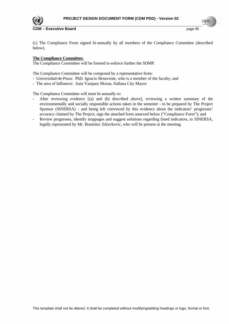
PROJECT DESIGN DOCUMENT FORM (CDM PDD) - Version 02 CDM – Executive Board page 85
This template shall not be altered. It shall be completed without modifying/adding headings or logo, format or font.
(c) The Compliance Form signed bi-annually by all members of the Compliance Committee (described below). The Compliance Committee: The Compliance Committee will be formed to enforce further the SDMP. The Compliance Committee will be composed by a representative from: - Universidad-de-Piura: PhD. Ignacio Benavente, who is a member of the faculty; and - The area of Influence: Isais Vazquez Moran, Sullana City Mayor The Compliance Committee will meet bi-annually to: - After reviewing evidence [(a) and (b) described above], reviewing a written summary of the
environmentally and socially responsible actions taken in the semester - to be prepared by The Project Sponsor (SINERSA) - and being left convinced by this evidence about the indicators’ progresses’ accuracy claimed by The Project, sign the attached form annexed below (“Compliance Form”); and
- Review progresses, identify stoppages and suggest solutions regarding listed indicators, to SINERSA, legally represented by Mr. Branislav Zdravkovic, who will be present at the meeting.

PROJECT DESIGN DOCUMENT FORM (CDM PDD) - Version 02 CDM – Executive Board page 86
This template shall not be altered. It shall be completed without modifying/adding headings or logo, format or font.
Bi-annual Compliance Committee Meeting - Compliance Form
Goal 1: Environmental Sustainability Initiative Indicator87 Annual Cumulative Progress
Land Quality improvement
Number of trees sowed Of 1rst Semester = Of 2nd Semester =___________ As of March 31st =
Awareness Number of environmental educational programs for local population88 (i.e. energy savings, water savings, etc.)
Of 1rst Semester = Of 2nd Semester =___________ As of March 31st =
New Initiative In case The Sponsor desires to incorporate a new initiative to this Environmental-Sustainability-initiative list, it will have to be approved by the Verifier
N/A89
Goal 2: Socio-Economic Sustainability
Initiative Indicator90 Annual Cumulative Progress Education standards improvement
Grants provided for education of local population Of 1rst Semester = Of 2nd Semester =___________ As of March 31st =
Number of employees hired from local population Of 1rst Semester = Of 2nd Semester =___________ As of March 31st =
Purchases from local suppliers Of 1rst Semester = Of 2nd Semester =___________ As of March 31st =
Economic standards improvement
[Population that accesses electricity due to The Project’s action or cooperation] Divided by [viable opportunities91 on rural electrification proposed to The Project by third parties or identified by The Project management]
Of 1rst Semester = Of 2nd Semester =___________ As of March 31st =
New Initiative In case The Sponsor desires to incorporate a new initiative to this Socio-Economic-Sustainability-initiative list, it will have to be approved by the Verifier
N/A92
Identified stoppages, suggested solutions and other observations brought up in the meeting: _________ ________________________________________________________________________________________________________________________________________________________________________ (Annex extra-paper if necessary). ______________________________ ______________________________________ Universidad de Piura Representative The Project’s Area of Influence Representative _________________________________ The Sponsor Date of the Compliance Committee Meeting: 87 Yearly flow or yearly change 88 Local meaning people who are living in the direct or indirect area of influence for reasons other than The Project occurrence 89 Target will be set when indicator is created and also needs to be approved by the Verifier 90 Yearly flow or yearly change 91 Viable opportunities meaning positive Net Present Value projects 92 Target will be set when indicator is created and also needs to be approved by the Verifier

PROJECT DESIGN DOCUMENT FORM (CDM PDD) - Version 02 CDM – Executive Board page 87
This template shall not be altered. It shall be completed without modifying/adding headings or logo, format or font.
MP Steering CommitteeMP Steering Committee4L. Vieira4L. Costa4F. Liu
4L. Vieira4L. Costa4F. Liu
4 BranislavZdravkovic
4Milivoje Boljsakov
ERCP ManagementERCP Management4Redy Risco
Operating Margin Calculation - Responsible
Operating Margin Calculation - Responsible
Build Margin Calculation - Responsible
Build Margin Calculation - Responsible
4Redy Risco
4HoracioArrue
SupportSupport4Rajco Belanovic4Douglas Chavez
Monitoring Plan (MP) – Emissions Reductions Calculation Procedure
ERCP Organizational Structure
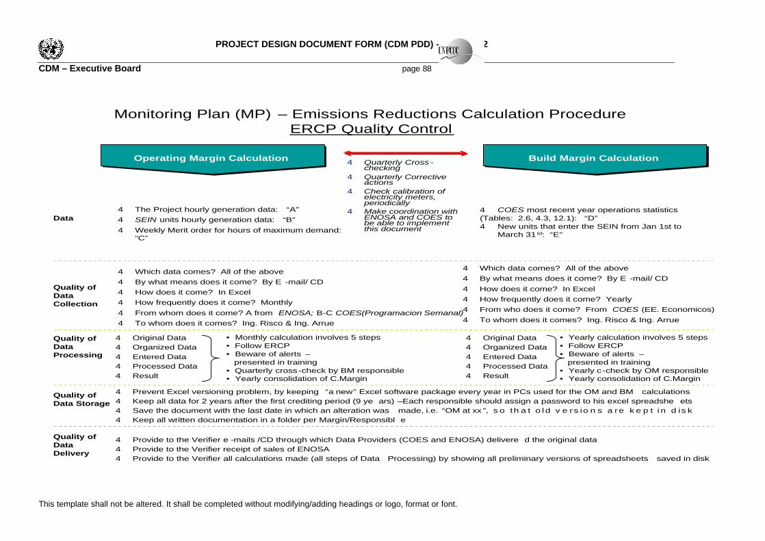
PROJECT DESIGN DOCUMENT FORM (CDM PDD) - Version 02 CDM – Executive Board page 88
This template shall not be altered. It shall be completed without modifying/adding headings or logo, format or font.
Monitoring Plan (MP) – Emissions Reductions Calculation ProcedureERCP Quality Control
Operating Margin CalculationOperating Margin Calculation Build Margin CalculationBuild Margin Calculation
4 Which data comes? All of the above4 By what means does it come? By E -mail/ CD4 How does it come? In Excel4 How frequently does it come? Monthly4 From whom does it come? A from ENOSA; B-C COES(Programacion Semanal)4 To whom does it comes? Ing. Risco & Ing. Arrue
4 The Project hourly generation data: “A”4 SEIN units hourly generation data: “B”4 Weekly Merit order for hours of maximum demand:
“C”
4 COES most recent year operations statistics (Tables: 2.6, 4.3, 12.1): “D”4 New units that enter the SEIN from Jan 1st to
March 31st: “E”
Data
Quality of DataCollection
4 Quarterly Cross -checking
4 Quarterly Corrective actions
4 Check calibration of electricity meters, periodically
4 Make coordination with ENOSA and COES to be able to implement this document
4 Original Data4 Organized Data4 Entered Data4 Processed Data4 Result
Quality ofData Processing
4 Prevent Excel versioning problem, by keeping “a new” Excel software package every year in PCs used for the OM and BM calculations4 Keep all data for 2 years after the first crediting period (9 ye ars) –Each responsible should assign a password to his excel spreadshe ets4 Save the document with the last date in which an alteration was made, i.e. “OM at xx ”, s o th a t o ld v e rs io n s a re k e p t i n d is k4 Keep all written documentation in a folder per Margin/Responsibl e
Quality ofData Storage
4 Provide to the Verifier e -mails /CD through which Data Providers (COES and ENOSA) delivere d the original data 4 Provide to the Verifier receipt of sales of ENOSA4 Provide to the Verifier all calculations made (all steps of Data Processing) by showing all preliminary versions of spreadsheets saved in disk
Quality ofData Delivery
4 Which data comes? All of the above4 By what means does it come? By E -mail/ CD4 How does it come? In Excel4 How frequently does it come? Yearly4 From who does it come? From COES (EE. Economicos)4 To whom does it comes? Ing. Risco & Ing. Arrue
4 Original Data4 Organized Data4 Entered Data4 Processed Data4 Result
• Monthly calculation involves 5 steps• Follow ERCP• Beware of alerts –
presented in training• Quarterly cross-check by BM responsible• Yearly consolidation of C.Margin
• Yearly calculation involves 5 steps• Follow ERCP• Beware of alerts –
presented in training• Yearly c-check by OM responsible• Yearly consolidation of C.Margin