prototype of an efficient hydropower planteprints.utar.edu.my/149/1/mh-2011-0703227-1.pdf · this...
TRANSCRIPT

PROTOTYPE OF AN EFFICIENT HYDROPOWER PLANT
ONG CHIAN SHEN
A project report submitted in partial fulfilment of the
requirements for the award of the degree of
Bachelor (Hons.) of Mechatronics Engineering
Faculty of Engineering and Science
Universiti Tunku Abdul Rahman
April 2011

ii
DECLARATION
I hereby declare that this project report is based on my original work except for
citations and quotations which have been duly acknowledged. I also declare that it
has not been previously and concurrently submitted for any other degree or award at
UTAR or other institutions.
Signature : _________________________
Name : ____ONG CHIAN SHEN____
ID No. : _______07UEB03227_______
Date : ______15 APRIL 2011 ______

iii
APPROVAL FOR SUBMISSION
I certify that this project report entitled “Prototype of an Efficient Hydropower
Plant” was prepared by Ong Chian Shen has met the required standard for
submission in partial fulfilment of the requirements for the award of Bachelor (Hons.)
of Mechatronics Engineering at Universiti Tunku Abdul Rahman.
Approved by,
Signature : _________________________
Supervisor : Dr. Stella Morris
Date : _________________________

iv
The copyright of this report belongs to the author under the terms of the
copyright Act 1987 as qualified by Intellectual Property Policy of University Tunku
Abdul Rahman. Due acknowledgement shall always be made of the use of any
material contained in, or derived from, this report.
© 2010, Ong Chian Shen. All right reserved.

v
Specially dedicated to
my beloved grandmother, mother and father

vi
ACKNOWLEDGEMENTS
With earnest gratitude and appreciation, I would like to take this opportunity to
acknowledge and extend my thanks to those whom have contributed in this project.
First and foremost, I offer my outmost gratitude to Universiti Tunku Abdul Rahman
(UTAR) for providing me opportunity to take this final year project as a partial
fulfilment of the requirement for Degree of Bachelor of Mechatronics Engineering.
Moving on, I would like to express my deepest gratitude to my research
supervisor, Dr. Stella Morris for her invaluable advice, commitment, guidance and
her enormous patience throughout the development of the research. It has been a
great adventure and experience during the undertaking of this project.
Next, I would like to thank my project partner, Chai Wei Chuan for patiently
working together on built up the prototype and performed experiments. He gave
precious ideals and group work on this project that saves up a lot of works for me.
In addition, I would also like to express my gratitude to my loving parent and
friends who had helped and given me encouragement in this project.

vii
PROTOTYPE OF AN EFFICIENT HYDROPOWER PLANT
ABSTRACT
This title of the project is designing a prototype of an efficient hydropower plant. The
project scopes were design, construct model, analyze, and implement to real world of
an efficient hydropower plant. The design objective is to build out a useful, effective,
convenience, reliable, environment friendly and safe to use hydropower plant.
Research has been done to fulfil the requirement. Different kinds of hydropower
plant have been going through to aid in gathering information and hence
implemented a new ideal of hydropower plant. The new hydropower plant from this
project was an efficient, portable and able to function in many different kind of flow
to generate electricity. The testing for this new design was carried out to meet the
objective of the design.

viii
TABLE OF CONTENTS
DECLARATION ii
APPROVAL FOR SUBMISSION iii
ACKNOWLEDGEMENTS vi
ABSTRACT vii
TABLE OF CONTENTS viii
LIST OF TABLES xi
LIST OF FIGURES xii
LIST OF SYMBOLS / ABBREVIATIONS xvi
LIST OF APPENDICES xvii
CHAPTER
1 INTRODUCTION 1
1.1 Background 1
1.1.1 Research and Background of Hydropower 3
1.1.2 Micro hydro power system (MHPS) overview 4
1.1.3 Environment Issue and Development of Micro
Hydro Power System 5
1.2 Aims and Objectives 6
1.3 Motivation 6
1.4 Outline of Report 6
2 LITERATURE REVIEW 8
2.1 Micro Hydro Power Plant 8
2.2 Impulse Turbine 9

ix
2.2.1 Pelton Wheel Turbine Design 10
2.2.2 Turgo Wheel Turbine Design 13
2.2.3 Cross-flow Turbine 15
2.2.4 Hydro-electric barrel generator (HEB)-Lowery
and Price’s design 17
2.2.5 Waterwheel 24
2.3 Reaction Turbine 28
2.3.1 Propeller Type Reaction Turbine 29
2.3.2 Francis Type Reaction Turbine 30
2.4 Comparison of the Micro Hydro Power Plant Design 31
3 METHODOLOGY 33
3.1 Phase of design (Planning of the project) 33
3.2 Recognition of Need 35
3.3 Gather Information 35
3.4 Conceptualization 36
3.5 Build and Fabricating 38
3.5.1 Turbine 38
3.5.2 Supporting 40
3.5.3 Generator 41
3.6 First Prototype 43
3.7 Testing 43
3.8 Prototype improvement 45
3.9 Implementation 47
3.9.1 Second Prototype 47
4 RESULTS AND DISCUSSIONS 49
4.1 The New Design Analysis 49
4.1.1 Description of The New Design 49
4.1.2 Equipment and Material Selection for the Design 52
4.1.3 Troubleshooting on the Design 54
4.1.4 Improved Design 56
4.2 Experiment 1 on the New Design: Depth Testing 56

x
4.2.1 Discussion on the experiment 1 57
4.3 Experiment 2 on the New Turbine: Different Kind of Flow 58
4.3.1 Discussion on the Experiment 2 60
4.4 Experiment 3 on the New Turbine: Different Medium 63
4.4.1 Discussion on the Experiment 3 64
4.5 Experiment 4 on the New Turbine: Impedance Matching
Test 65
4.5.1 Result from load test 66
4.5.2 Relationship between the gained results 68
4.5.3 Discussion on experiment 4 71
4.6 Efficiency Calculation 72
5 CONCLUSION AND RECOMMENDATIONS 74
5.1 Overall Conclusion 74
5.2 Project Achievement 75
5.3 Recommendation and Future Work 76
REFERENCES 77
APPENDICES 79

xi
LIST OF TABLES
TABLE TITLE PAGE
2.1 Efficiency with different flow rate 12
2.2 Head of Water turbine 31
2.3 Typical Efficiency of Turbines 32
4.1 Data of 10cm dept of the blade in the water 56
4.2 Data of 3cm dept of the blade in the water 56
4.3 Data of testing in a water tank and river 59
4.4 Average Voltage in a water tank and river 61
4.5 Data of testing in air medium with vertical and
horizontal position of turbine 63
4.6 Result computation for 10 ohms Resistor 66
4.7 Result computation for 50 ohms Resistor 66
4.8 Result computation for 100 ohms Resistor 67
4.9 Result computation for 150 ohms Resistor 67
4.10 Result computation for 200 ohms Resistor 68
4.11 Voltage and Resistance Value 68
4.12 Current and Resistance Value 69
4.13 Power and Resistance Value 70

xii
LIST OF FIGURES
FIGURE TITLE PAGE
1.1 Hydro Power Plant 2
1.2 Water Cycle 2
1.3 Niagara Fall Hydro Power Plant 3
2.1 Impulse Turbine 9
2.2 Pelton Turbine 10
2.3 Pelton Turbine Working Principle 10
2.4 Pelton Turbine Testing 11
2.5 The relationships between tangential force on the
brake lever and rotational speed of the turbine at
the three water volume flow rates. 13
2.6 Turgo Turbine 13
2.7 Turgo Turbine Working Principle 14
2.8 Turgo Turbine Testing 15
2.9 Cross-Flow Turbine 15
2.10 Cross-Flow Turbine working Principle 16
2.11 Cross-Flow Turbine Testing 17
2.12 Hydro-electric Barrel Generator (HEB)-Lowery
and Price’s Design 17
2.13 Hydro-electric Barrel Generator (HEB) Working
Principle 18
2.14 HEB Generator View 19

xiii
2.15 HEB Barrel Body View 20
2.16 HEB Barrel Body View (without generator) 21
2.17 HEB Barrel Internal View (without generator) 21
2.18 HEB Sling 22
2.19 HEB Possible Sling 22
2.20 HEB Output Power Model 1 23
2.21 HEB Output Power Model 2 23
2.22 Waterwheel 24
2.23 Overshot Waterwheel 25
2.24 Breadshot Waterwheel 26
2.25 Undershot Waterwheel 27
2.26 Reaction Turbine 28
2.27 Bulb Turbine 29
2.28 Kaplan Turbine 29
2.29 Francis Turbine 30
3.1 Phase of Design 34
3.2 New Design Micro Hydro Power Plant Turbine 36
3.3 Fabrication Flow Chart 38
3.4 Turbine Drive Shaft 39
3.5 Turbine Connector 40
3.6 Supporting Framework 40
3.7 Supporting Bearing 41
3.8 Generator 42
3.9 Gears 42
3.10 First Prototype 43
xiv
3.11 Depth of Blade 44
3.12 Testing Water Tank 44
3.13 Testing River 45
3.14 High Pressure Water Jet (Bosch Aquatak 100) 45
3.15 Hole Drilled on the Turbine Blade Holder 46
3.16 Better Generator (Cytron Motor) 46
3.17 Improvement of the Second Prototype 47
3.18 Second Improved Prototype 48
4.1 New Turbine Design of Micro Hydro Power Plant 49
4.2 New Design on Flowing Water 51
4.3 Side View of Flexible Blade on The New Design 51
4.4 Top View of Flexible Blade on The New Design 51
4.5 New Design Micro Hydro Power Plant Turbine
with Selected Material 52
4.6 Software Pressure Flow Analysis 53
4.7 Bad Alignment of The First Prototype 55
4.8 Water Tank Testing 57
4.9 Closing Process of the Functioning Blade 58
4.10 Voltage Along Time at Different Flows 59
4.11 River Testing 60
4.12 Turbine Blade That Block Flow 62
4.13 Turbine Affection Theory 62
4.14 Vertical Position Turbine 63
4.15 Horizontal Position Turbine 64
4.16 Graph of Voltage versus Resistance 69
4.17 Graph of Current versus Resistance 70

xv
4.18 Graph of Power versus Resistance 71
5.1 Portable Turbine 75

xvi
LIST OF SYMBOLS / ABBREVIATIONS
F tangential force, N
g the acceleration due to gravity (9.81 m/ )
h the available head of the water source , cm
I current, A
l moment arm length, m
P power, W
Ps mechanical power available in the turbine shaft, W
Pw extractable power of a water jet, W
Q volumetric flow rate, m3/s
R resistance, Ω (or ohms)
r rotational speed of the shaft, rpm
V voltage, V
ηm mechanical efficiency (dimensionless)
π pi (3.142)
ρ density of the water, kg/m3
CAD computer –aided design
DC direct current
HEB hydro-electric barrel
MHPS micro hydro power system
POM polyoxymethylene
RPM revolution per minute

xvii
LIST OF APPENDICES
APPENDIX TITLE PAGE
A Gantt Chart 79
B Generator Specification 81

CHAPTER 1
1 INTRODUCTION
1.1 Background
Hydropower is produced by converting the potential energy of river water to kinetic
energy via a turbine, and then to an electrical energy via a generator. The quantity of
electricity generated is determined by the volume of water flow and the amount of
head (the height from turbines in the power plant to the water surface) created by the
water reservoir.
A typical hydropower plant includes a dam or a mountain reservoir,
penstocks, a powerhouse and an electrical power substation. The reservoir stores
water and creates the head; penstocks carry water from the reservoir to turbines
inside the powerhouse; the water rotates the turbines, which drive generators that
produce electricity (Hydroelectric Power , July 2005).
2
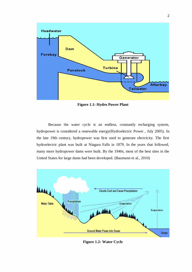
Figure 1.1: Hydro Power Plant
Because the water cycle is an endless, constantly recharging system,
hydropower is considered a renewable energy(Hydroelectric Power , July 2005). In
the late 19th century, hydropower was first used to generate electricity. The first
hydroelectric plant was built at Niagara Falls in 1879. In the years that followed,
many more hydropower dams were built. By the 1940s, most of the best sites in the
United States for large dams had been developed. (Baumann et al., 2010)
Figure 1.2: Water Cycle

3
Figure 1.3: Niagara Fall Hydro Power Plant
Hydro power is a very clean source of energy and only uses the water, the
water after generating electrical power, is available for other purposes. Due to this
reason, hydropower plants become more and more importance. There are few type of
hydropower plant which depends on the size which is the large, small, mini, micro,
and Pico (Hydropower Energy Technologies Worldwide, 2009) :-
1. Large Hydro (10 MW or more of generating capacity)
2. Small Hydro (1 to 10 MW of generating capacity)
3. Mini Hydro (100 KW to 1 MW of generating capacity)
4. Micro Hydro (5 KW to 100 KW of generating capacity)
5. Pico Hydro (less than 5 KW of generating capacity)
1.1.1 Research and Background of Hydropower
Hydropower is one of the most important renewable energy in the world. Hence
development of hydropower has growth widely in the world and issue like
environment, cost and efficiency has take into consideration in the research.

4
Until about 1980, hydropower research and development (R&D) efforts
focused mainly on improving turbine efficiency and reducing noise and vibration that
can cause damage to turbine blades. These early R&D efforts led to a 30% increase
in turbine efficiencies. In 1993, the U.S. Department of Energy (DOE) initiated an
effort to develop advanced hydropower turbine systems (AHTS) to improve the
overall performance and acceptability of hydropower projects. Turbine, safe pass
way for fish, improving mitigation practice are few issue that taken by DOE in
hydropower research (Sale et al., 2008).
On the outskirts of Accra, Ghana, business plans are only as final as the next
electricity outage permits. In July, food tins at the Prime Pak canning factory were
positioned on the assembly line, ready to be sealed before export. Without warning,
the machines came to a screeching halt, leaving entrepreneur Cyril Francis standing
helplessly in the dark. Thirty per cent of the consignment spoiled. All this has
stimulated Ghana government to build an additional hydroelectric project on the
Black Volta River. The $700 mn Bui project would have a generation capacity of
400 mw to the country (Madamombe, 2005).
Lately, Universiti Tunku Abdul Rahman (UTAR) study carry out by UTAR’s
doctoral student Koh Siong Lee and supervisor Dr Lim Yun Seng has found that
hydropower and biomass are feasible alternatives to a coal-fired power plant in
Sabah. These options meet key objectives of the National Energy Policy, which
include promoting the use of clean energy and minimising negative impact of power
production to the environment. Results also show these renewable and green options
are not only environment friendly but also cost-effective and technologically proven.
(Hydropower more cost-effective than coal-fired plant, says Utar study, june 4, 2010).
1.1.2 Micro hydro power system (MHPS) overview
Micro hydropower system is an efficient and reliable form of energy in nowadays.
This system is popular in third world country (developing country), especially those
rural areas that are not well connected with electricity. Most of the MHPS are operate

5
in isolated form, because of the population in the rural area are small and sparsely
distributed and the extension of grid system is not financially feasible because of
high cost investment required for transmission line. Micro hydro power system
(MHPS) is relatively small sources that are appropriate in many cases for individual
users or groups of users who are independent of the electricity supply grid. Although
this technology is not new, its wide application to small waterfalls and other potential
sites are new. It is best suited to high falls with low volume, such as occur in high
valleys in the mountains. A micro hydro power system (MHPS) is the application of
hydroelectric power on a commercial scale serving a small community and is
classified by power and size of waterfall; MHPS normally which has less than
100kW capacity (Saket, 2008).
1.1.3 Environment Issue and Development of Micro Hydro Power System
A micro hydro system is a more environment friendly renewable energy. This is
because the hydraulic works can be made simple and large constructions such as
dams are usually not required. This MHPS is simple to be installed due to the parts
like pipes, generators and others are usually cheap and easy to find (Saket, 2008).
In recent decade, the environment impact for a large hydro power plant has
take into consideration by the local government. This is because, due to the
opposition from local resident who living on the land nearby to be flooded, it is
difficult for the new dam to be developed. Hence, people start to realize the
important of the smaller hydro system like MHPS (Mohibullah et al., 2004).
This hydro power system has become more and more important due to few
reasons. The first is the system is this system is close to the demander place, hence
building cost is way much cheaper and the money is saved up. Besides, micro hydro
power system has become more demandable due to the increasing of energy price
worldwide (Bockman et al, 2007).

6
1.2 Aims and Objectives
The main objective of doing this project is to focus on the designation of an efficient
and cost effective micro hydropower prototype which able to generate electricity for
basic use and citizen in rural area. Besides the main objective, this project also aims
to bring awareness to world about the good of a renewable energy over pollution.
The study of micro hydropower which includes some engineering skill will be
carrying out to meet the main objective of this project.
1.3 Motivation
Due to the greenhouse effect gas emission and also the global warming problem that
face by the world nowadays, renewable energy become more and more important.
Besides, the technology has also increase the world energy consumption and this will
more or less inspires the world look over the free renewable energy like hydropower
that might be a solution for the above two problem that faced.
This project will be carrying out throughout the whole year, knowledge will be
adopted to produce the most effective and suitable outcome.
1.4 Outline of Report
Chapter 2 - Literature Review describes different kind of turbine and waterwheel for
hydropower plant which will help in designing the micro hydropower plant.
Chapter 3 - Research Methodology describes the overall process, steps and
calculation in designing the micro hydropower plant.

7
Chapter 4 - Result and Discussion describes the different approaches that adopted
like experiment test on different kind of designed to meet the objective of the project.
Chapter 5 - Conclusion and Recommendation describe how well the final
implementation meets the design specification and provide further suggestion for
improvement that can be made.

CHAPTER 2
2 LITERATURE REVIEW
2.1 Micro Hydro Power Plant
Micro Hydro Power Plant today is connected either directly to the generator or is
connected by means of gear or belts and pulleys, depending on the speed required for
the generator. Micro Power Plant depends mainly on the head and the design flow for
the generator. Other deciding factors include how deep the turbine must be set,
efficiency, and cost. Turbine that used in hydro power system can be classified in to
2 groups. First is the impulse and follow by the reaction turbine.(Saket, july 21,
2008).

9
2.2 Impulse Turbine
Figure 2.1: Impulse Turbine
The impulse turbine generally uses the velocity of the water to move the runner and
discharges to atmospheric pressure. Water stream will hits each bucket on the runner.
There is no suction on the down side of the turbine, and the water will flows out the
bottom of the turbine housing after hitting the runner. Impulse turbine is generally
suitable when high head, low flow applications.(Types of Hydropower Turbines,
2005). There are few example of impulse turbine. For example like the Pelton, Turgo
and Cross Flow. (Saket, july 21, 2008). The main different of these turbine is design
of the turbine blade of each turbine is unique. Besides, the way of discharging water
away from each of the turbines blades are also unique. For example like the Pelton
and Closs Flow will discharge water through the upper position of the blade and the
Turgo will discharge through the side position. All this is fully depend on their
unique design of the blade which can be observed a in the following figures. This
design normally is more suitable for water fall area. (Norman, 2003)

10
2.2.1 Pelton Wheel Turbine Design
Figure 2.2: Pelton Turbine
2.2.1.1 Description of the Design
Figure 2.3: Pelton Turbine Working Principle

11
Pelton turbine is an impulse turbine. This is designed by a man call Lester Allan
Pelton in the 1880’s. The wheel is fitted with vanes evenly spaced about its
circumference. Unlike old wheel designs, each vane is actually composed of two
cups joined by a sharp ridge. Water flow is directed by one or more nozzles to strike
the ridge of each vane tangentially in succession and in turn delivers the water's
kinetic energy in impulses. Hence, the turbine is classified as an impulse turbine. In
principle, the ridge acts to divide the water jet in order to achieve better mechanical
efficiency. With an optimised jet and cup geometry, more than 90% of the power of
the water jet can be transformed into mechanical power by the turbine shaft.(Rasi, 7,
July 2008)
2.2.1.2 Testing of the Design
A laboratory-scale Pelton turbine for hydroelectric generation has been constructed
and used in the educational curriculum of The Renewable Energy Programme at the
University of Jyväskylä, Finland to test out the turbine efficiency. (Rasi, 7, July 2008)
The apparatus is simple to make and the author uses inexpensive components
to construct the turbine as shown in figure 2.2. The turbine vane is made out of
Polyoxymethylene (POM) plastics and one end of the turbine shaft extends through
the wall of the housing and is fitted with a pulley wheel, which drives a small DC
electric generator by use of a rubber belt. The generator itself is a salvaged motor
from a DC cooling fan. (Rasi, 7, July 2008)
Figure 2.4: Pelton Turbine Testing

12
The testing build up is as indicate in figure 2.4 and the testing was test out
with different flow and different load of resistors. The author has use equation 2.1 to
calculate the efficiency of the turbine. (Rasi, 7, July 2008)
(2.1)
Where
= mechanical efficiency
= mechanical power available in the turbine shaft
= extractable power of a water jet
= density of the water
= the acceleration due to gravity (9.81 m/ )
= the available head of the water source
= volumetric flow rate
= pi (3.142)
= rotational speed of the shaft
= moment arm length
= tangential force
The author has conclude that the design have an efficiency of 0.47±0.02 for a
water flow rate of 0.171/s as listed in the table 2.1 and shown in figure below.(Rasi,
7, July 2008). Hence, this design efficiency will be around 80-90%.
Table 2.1: Efficiency with different flow rate
Water Flow Rate, Q (L/s) Mechanical Efficiency,
0.14 0.45
0.17 0.47
0.20 0.46

13
Figure 2.5: The relationships between tangential force on the brake lever and
rotational speed of the turbine at the three water volume flow rates.
2.2.2 Turgo Wheel Turbine Design
Figure 2.6: Turgo Turbine

14
2.2.2.1 Description of Design
Figure 2.7: Turgo Turbine Working Principle
A Turgo Wheel is a variation on the Pelton and is made exclusively by Gilkes in
England. The Turgo runner is a cast wheel whose shape generally resembles a fan
blade that is closed on the outer edges. The water stream is applied on one side, goes
across the blades and exits on the other side.
2.2.2.2 Testing of the Design
Turgo turbine testing is just same like testing a Pelton turbine. This turgo design can
be test out exactly same like tested for Pelton design turbine. The testing build up is
as indicate in figure 2.8 and the testing was test out with different flow and different
load of resistors. The efficiency of this turbine is just the same like the Pelton turbine.
(John S. Anagnostopoulos, 2007). This turbine design efficiency will be around 80-
95%. (Micro-Hydropower System; A Buyer's Guide, 2004)

15
Figure 2.8: Turgo Turbine Testing
2.2.3 Cross-flow Turbine
Figure 2.9: Cross-Flow Turbine

16
2.2.3.1 Description of the Design
Figure 2.10: Cross-Flow Turbine working Principle
Cross-Flow turbine is a water turbine developed by the Australian Anthony Michell,
the Hungarian Donát Bánki and the german Fritz Ossberger. Michell obtained
patents for his turbine design in 1903.
A cross-flow turbine is drum-shaped and uses an elongated, rectangular-
section nozzle directed against curved vanes on a cylindrically shaped runner. It
resembles a "squirrel cage" blower. The cross-flow turbine allows the water to flow
through the blades twice. The first pass is when the water flows from the outside of
the blades to the inside; the second pass is from the inside back out. A guide vane at
the entrance to the turbine directs the flow to a limited portion of the runner. The
cross-flow was developed to accommodate larger water flows and lower heads than
the Pelton.

17
2.2.3.2 Testing of the Design
Testing for this design is also the same like all impulse turbines. We can connect the
turbine with load and using a nozzle to create water flow into it. However the result
from this turbine was not that good if compare to other two, this design can only
produce around 65% to 85% of efficiency if compare with the other with the high
efficiency of 80% to 95% for Turgo turbine and 80% to 90% for Pelton design.
Figure 2.11: Cross-Flow Turbine Testing
2.2.4 Hydro-electric barrel generator (HEB)-Lowery and Price’s design
Figure 2.12: Hydro-electric Barrel Generator (HEB)-Lowery and Price’s Design

18
2.2.4.1 Description of the design
Figure 2.13: Hydro-electric Barrel Generator (HEB) Working Principle
This Hydro-electric barrel generator is design by Lowery and Price’s and the
designers have got the patent on the 8th September of 2008. The whole structure is on
the flowing water. This is a floating waterwheel that can generate electricity when
suspended over a river or other flowing water regardless of the depth and speed of
flow (the designers stated that the depth will only take into consideration when
installation and set up where the user have to place the generator stand at the bottom
of the river).
The barrel was one-piece moulded plastic with paddle treads and two integral
planet gear driven permanent magnet generators installed making this a relatively
light assembly for transportation and installation. The rotating barrel turns the
generator case which drives the planet gears which in turn spin the discs which holds
the permanent magnets. The movement of the magnets induces electrical current in
the coils which are held stationary. The unique chevron shaped paddle treads give the
barrel the ability to rotate about its horizontal axis in fast flowing water, entering the
water smoothly and re-surfacing without lifting water.

19
The merit of this design is the significant reduction of any down force and the
elimination of the bow wave in front of the barrel as it rotates at the same speed as
the flow of water, thus increasing the efficiency of the machine.
This design has many advantages over other methods of hydroelectric power
production. The advantages will be stated as below:
Quiet operation compared to conventional waterwheel
Easy to transport and install
Environmentally friendly due to shallow draft
Cost effective to manufacture, low capital outlay per kilowatt
Does not significantly interrupt river flow and can roll over debris
Adjusts to water level
Tidal estuary variant
Massive potential for grants
2.2.4.1.1 The HEB Generator
Figure 2.14: HEB Generator View

20
This would be a brush-less permanent magnet type as this type can produce high
currents at low revolutions and its "pancake" format is ideal for this device as
indicate in the figure 2.14. The illustration shows the concept involved. Harnessing a
large force at low speed may require some form of gearing as illustrated. However a
small diameter HEB on a fast stream could perhaps drive the armature directly and
benefit from the energy saving lost through gearing. A brush-less generator will of
course require less maintenance and the vented "pancake" design facilitates cooling.
There is a planet gear for more stability and the coil and magnet to generate
electricity.
2.2.4.1.2 The HEB barrel
This design is like a balloon that float on the river. As the HEB is completely sealed
it could be an option to install a valve to maintain slight internal pressure improving
rigidity. This valve would vent during periods of hot weather to protect the barrel. A
more clearer picture about the barrel will be shown at the figures below.
Figure 2.15: HEB Barrel Body View

21
Figure 2.16: HEB Barrel Body View (without generator)
Figure 2.17: HEB Barrel Internal View (without generator)
2.2.4.1.3 Sling (support frame)
This would be left to the developer but a common component is that the Swing tube
is mounted above the height of the barrel. Shown in the figure below are 3 of the
designs as examples, depending on location, suitable river bank, average water speed
or size of barrel. The single stanchion design could possibly have the capability to
swing the barrel round on to the bank for cleaning and maintenance. The frames
could incorporate navigation lights.

22
Figure 2.18: HEB Sling
2.2.4.1.4 A possible sling design for the purpose of prototyping
This consists mainly of common scaffolding parts but could be fabricated out of
whatever is available. The structure is held anchored by the two baskets filled with
rocks, bricks, sandbags or hardcore. As a temporary structure it may be useful in
situations where planning permission is an issue. Anchoring to one bank avoids other
problems such as requiring access to the other bank or problems anchoring to the
riverbed. It is fairly unobtrusive as it would straddle a riverbank path.
Figure 2.19: HEB Possible Sling

23
2.2.4.2 Testing of the Design
The output power can be estimate using 2 different method by the designers.
Calculation using simple formula for Power
Horsepower = Torque (foot pounds) x 2 pi x rpm / 33000 which simplifies to:
Horsepower = Torque x rpm / 5252.
Finding Torque by calculating the water pressure on the paddle area using:
Paddle Area x Length x density of water x (Velocity of current2 / 2 x gravitational
constant) and multiplying this by Radius
Figure 2.20: HEB Output Power Model 1
Figure 2.21: HEB Output Power Model 2

24
2.2.5 Waterwheel
Figure 2.22: Waterwheel
As the water flow from the higher level to the lower level of the water wheel, this
will cause the turning of the wheel. From the angle of energy, the potential energy
will be converted into the kinetic energy when the wheel turns. Then this will create
a mechanical energy and turn the generator that is attached to this. Hence, it will
create electricity when the generator turned. There are 3 type of waterwheel in hyfro
electricity which is the overshot, undershot and the breadshot. All have their own
function. (Jones, 2005). This design normally is suitable for a water fall.(Norman,
2003)

25
2.2.5.1 Overshot waterwheel
Figure 2.23: Overshot Waterwheel
This type of waterwheel will let the water enter from the above of the wheel and falls
into the buckets turning the wheel with efficiency of about 85%. the head diameter
for this is normally between 2.5m to 10m and the flow rate will be lesser than 0.2
/s per m width.

26
2.2.5.2 Breadshot waterwheel
Figure 2.24: Breadshot Waterwheel
This type of waterwheel will let water enters half way up the diameter of the wheel,
falling into buckets turning the wheel. The efficiency is up to 87%. The head
diameter is normally between 1.5m to 3m. The flow rate will be between 0.3 to 0.65
/s per m width.

27
2.2.5.3 Undershot waterwheel
Figure 2.25: Undershot Waterwheel
This type of wheel can be defined into 2 types. The first is where some modules use
a very small head drop and curved blades to take potential energy from the river and
this will give around 60 to 77 % of efficiency. While other will use the kinetics
energy of the river on the blades but this will give only 33% of efficiency. The head
diameter is normally between 0.3m to 2.0m. The flow rate will be between 0.45 to 1
/s per m width.

28
2.3 Reaction Turbine
Figure 2.26: Reaction Turbine
A reaction turbine develops power from the combined action of pressure and moving
water. The runner is placed directly in the water stream flowing over the blades
rather than striking each individually. Reaction turbines are generally used for sites
with lower head and higher flows than compared with the impulse turbines. This
design will more suitable for a flowing river or a quiet river.(Norman, 2003)

29
2.3.1 Propeller Type Reaction Turbine
Figure 2.27: Bulb Turbine
Figure 2.28: Kaplan Turbine
2.3.1.1 Propeller Type Reaction Turbine Working Principle
A propeller turbine generally has a runner with three to six blades in which the water
contacts all of the blades constantly. Picture a boat propeller running in a pipe.

30
Through the pipe, the pressure is constant; if it isn't, the runner would be out of
balance. The pitch of the blades may be fixed or adjustable. The major components
besides the runner are a scroll case, wicket gates, and a draft tube. There are several
different types of propeller turbines. The first is the bulb turbine where the turbine
and generator is a sealed unit placed directly in the water stream. The second is the
straflo where the generator is attached directly to the perimeter of the turbine. The
third is the tube turbine where The penstock bends just before or after the runner,
allowing a straight line connection to the generator. The last is the Kaplan turbine
where both the blades and the wicket gates are adjustable, allowing for a wider range
of operation.
2.3.1.2 Testing of the Design
This type of turbine will only work well when the water pressure is constant, the
runner will be out of balance if the pressure is too high. According to the Micro
Hydro Plant Buyer’s Guide book stated that this turbine will give around 80% to
95% of efficiency. (Micro-Hydropower System; A Buyer's Guide, 2004)
2.3.2 Francis Type Reaction Turbine
Figure 2.29: Francis Turbine

31
2.3.2.1 Francis Type Reaction Turbine Working Principle
A Francis turbine has a runner with fixed buckets (vanes), usually nine or more.
Water is introduced just above the runner and all around it and then falls through,
causing it to spin. Besides the runner, the other major components are the scroll case,
wicket gates, and draft tube.
2.3.2.2 Testing of the Design
This design will be more stable compare to the propeller type design. According to
the Micro-Hydropower system buyer guide’s book, this type of design has an
efficiency of 80% to 90%. (Micro-Hydropower System; A Buyer's Guide, 2004)
2.4 Comparison of the Micro Hydro Power Plant Design
The table below is the some group of Micro Hydro Power Plant and the needed head
for all kind of turbines.(Micro-Hydropower System; A Buyer's Guide, 2004)
Table 2.2: Head of Water turbine
Turbine
Runner
High Head
(more than
100m / 325ft.)
Medium Head
(20 to 100m /
60 to 325 ft.)
Low Head
(5 to 20m / 16
to 60 ft.)
Ultra-Low
Head
(less than 5m/
16 ft.)
Impulse Pelton , Turgo Cross-flow,
Turgo
Cross-flow Water Wheel
Reaction - Francis Propeller Propeller

32
The table below will be the efficiency of all kind of the Micro Hydro Power Plant
design. (Micro-Hydropower System; A Buyer's Guide, 2004)
Table 2.3: Typical Efficiency of Turbines
Micro Hydro Power Plant Design Efficiency Range
Impulse turbine :
Pelton
Turgo
Cross-flow
Water wheel undershot
Water wheel breadshot
Water wheel overshot
80 – 90%
80 – 95%
65 – 85%
25 – 45%
35 – 65%
60 – 75%
Reaction turbine :
Francis
Propeller
Kaplan
80 – 90%
80 – 95%
80 – 90%

CHAPTER 3
3 METHODOLOGY
3.1 Phase of design (Planning of the project)
A phase of design is like drawing a map for the project. This is to guide the author
through out the project. A flow chart can be map in this project. A good flow chart is
to formulate the satisfaction of a project manager need. The outline of the flow chart
that used in this project will be as indicate in figure 3.1. Besides, a Gantt chart
(appendix a) will be drawn to describe and monitor about the planning process for
the prototype in which have to perform on specific period.

34
Figure 3.1: Phase of Design
Planning of the
project
Recognition of need
Gather information
Conceptualization
Build and fabricate
Requirement
met?
Troubleshooting
NO
Implementation
YES
Testing

35
3.2 Recognition of Need
Normally design of a Micro Hydro Plant is site-specific but there are still things that
are in common for all Micro Hydro Plants. This step will tell the author the basic
need and common thing of all the micro hydro power plant. For example, a water
supply is needed for all the plants- this can be water flow down from the water fall
from the mountain or a water flow from the river. Relying on a minimal flow of
water year-round for some of the countries, an artificial reservoir might solve the
problem. Of cause all of the Micro Hydro Plants, they do not need a damn to
function. If the Micro Hydro Plant is apart from the water supply, a penstock pipe
might be needed to carry the supplied water to generate power.
A common Micro Hydro Plant will need a turbine and generator to function.
As for the turbine, different Micro Hydro Plant might have different turbine design.
In this project, a specific design of turbine might be needed to increase the efficiency
of the existing Micro Hydro Plant concept. A turbine turn the generator, which then
connected to the electric loads. The connection can be just a simple bulb to the
complicated housing areas. These are the basic need to create a Micro Hydro Plant
that the author has to know at the first step of designing a new micro hydro power
plant.
3.3 Gather Information
Case study through out the world via different sources. For example, Pelton turbine;
one of the most popular and great design of Micro Hydro Plant today. Research is
made on this concept and many others to aid in designing a more efficient and new
Micro Hydro Plant.
With the limited budget, the author has to be extra careful when come to
collecting information for the few basic need of the new Micro Hydro Plant. For
example like the generator, material selection, the environment, and so on.
Consideration has to be taken into their characteristic that mostly from different

36
angle kind of view related. For example like their ability and properties. Besides,
reliability for long term use and commercial are importance. Hence, indirectly cost
has become the importance issue to consider.
3.4 Conceptualization
Figure 3.2: New Design Micro Hydro Power Plant Turbine
By obtaining sufficient information for each part of the prototype design, it has
provides a better solution when constructing the prototyping. This step is to generate
a wide range of design option and this is where the author use creativity and
imagination to develop approaches to achieve the design objective while satisfying
the constraints. Hence, with few considerations, the author has come out with a new
design ideal of micro hydro power plant as indicate in the figure 3.3.
This concept will be draw out using a 3D mechanical computer-aided design
(CAD) program; Solidwork. This mechanical design automation software is a
featured based, parametric solid modelling design tool. The author was able to create
fully associate 3D solid models with or without constraints while utilizing automatic

37
or the author can defined relations to capture design intent. Using this 3D mechanical
computer-aided design (CAD) program in creating the author concept micro hydro
power plant turbine, it allow the author to work easily, intelligently in understanding
the author new concept of micro hydro power plant geometric features. This software
is giving better services to the author in designing the new concept of micro hydro
power plant turbine. This program not only reduce the errors and provide an easy
way in achieving a prefect model, but also carries with important information and
data to the author such as dimension of the turbine, material selection, hardness and
strength of the material. Besides, with the Solidwork program the author are allow
capturing their own design intent and also make changes or modification to the
model easily and quickly. With the aid of computer, simulation has been done by the
author to get the optimize dimension before constructing the real prototype. Besides
the simulation, this software also shows the author the working principle and
reliability of the new ideal. Material for this prototype also has been considered by
the author. With the hardness and strength analysis, plastic and aluminium will be
consider so that it will give a lighter weight and prevent the prototype from
deteriorate and rust.

38
3.5 Build and Fabricating
Figure 3.3: Fabrication Flow Chart
The fabrication process was carried out to build author’s micro hydro power plant
new idea design as like the flow chart above. The dimension of the material was
selected in the software used with some analysis. With the basic design that has
drawn out with the software. The author can fabricate easily with the drawing
prepared earlier.
3.5.1 Turbine
3.5.1.1 Drive Shaft
The drive shaft is the main support and carries the blades of the new design turbine.
Hence, this is an importance part. A stainless steel hollow shaft was chosen by the
author. Besides, a square aluminium hollow shaft was added to hold all the 4 blade of
the turbine. Bolts, nuts, and washer will be joining both of this part together.
Software drawing as a
guide for fabrication.
Build turbine
Build support
Build generator
Prototype as outcome

39
Figure 3.4: Turbine Drive Shaft
3.5.1.2 Turbine blade
The turbine blades will be the part that contacts the most with the water so that it can
provide a reaction to generate electricity. All this part will be join together with bolt,
nuts and also washers. Besides, there are extra butterfly hinges added to the blade for
the ideal of portable. This will be shown in the figure 3.5.
Stainless steel hollow
shaft
Square aluminum
hollow shaft

40
Figure 3.5: Turbine Connector
3.5.2 Supporting
3.5.2.1 Supporting framework
This part was fully depended on the turbine and the environment itself. The
dimension will be obtain from there and hence the author has chosen an L shape steel
to build up the supporting frame as indicated in the figure 3.5 after the turbine and
the drive shaft is built.
Figure 3.6: Supporting Framework
Butterfly hinge added
for portable idea.
Combination of bolts,
nuts, and washer to fix
the blade on the shaft.

41
3.5.2.2 Supporting bearing
A bearing will be added to hold the turbine and the supporting framework. So that
the design turbine will be able to rotate on the supporting frame. The bearing will be
select according to the size of the design shaft and UCF 205 bearing was chosen for
the prototype. The author has only chosen one bearing to hold the prototype, so that
this will not be a burden for the turbine.
Figure 3.7: Supporting Bearing
3.5.3 Generator
3.5.3.1 Generator selection
Generator is another importance part of the design turbine. From the information
gather, an induction generator will be select. Hence, the author has chosen a 12V ac
generator.

42
Figure 3.8: Generator
3.5.3.2 Speed increasing mechanism
For a low speed generator (normally less than 1000 RPM), a speed increasing
mechanism such as belt and or gear box is required to increase the turning speed of
the generator, hence provide a higher RPM. According to the author, 2 gears have
been select to increase the RPM of the generator to give a clearer picture when
running the test. One of the gears will have 160 teeth and the smaller one will have
106 of teeth as indicate in the figure 3.6.
Figure 3.9: Gears
160 teeth 106 teeth
43
3.6 First Prototype
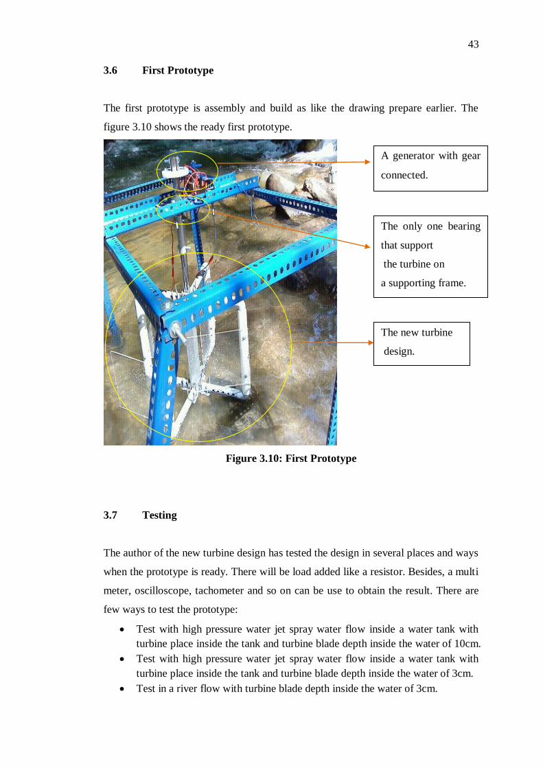
The first prototype is assembly and build as like the drawing prepare earlier. The
figure 3.10 shows the ready first prototype.
Figure 3.10: First Prototype
3.7 Testing
The author of the new turbine design has tested the design in several places and ways
when the prototype is ready. There will be load added like a resistor. Besides, a multi
meter, oscilloscope, tachometer and so on can be use to obtain the result. There are
few ways to test the prototype:
Test with high pressure water jet spray water flow inside a water tank with
turbine place inside the tank and turbine blade depth inside the water of 10cm.
Test with high pressure water jet spray water flow inside a water tank with
turbine place inside the tank and turbine blade depth inside the water of 3cm.
Test in a river flow with turbine blade depth inside the water of 3cm.
A generator with gear
connected.
The only one bearing
that support
the turbine on
a supporting frame.
The new turbine
design.
44
Test with at horizontal position of the turbine with water pressure pump spray
on the turbine blade.
Test with vertical position of the turbine with water pressure pump spray on
the turbine blade.
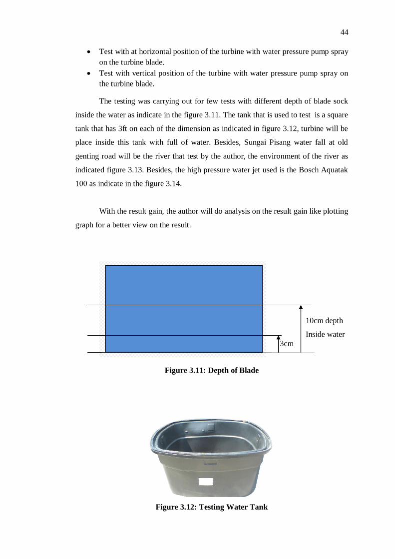
The testing was carrying out for few tests with different depth of blade sock
inside the water as indicate in the figure 3.11. The tank that is used to test is a square
tank that has 3ft on each of the dimension as indicated in figure 3.12, turbine will be
place inside this tank with full of water. Besides, Sungai Pisang water fall at old
genting road will be the river that test by the author, the environment of the river as
indicated figure 3.13. Besides, the high pressure water jet used is the Bosch Aquatak
100 as indicate in the figure 3.14.
With the result gain, the author will do analysis on the result gain like plotting
graph for a better view on the result.
Figure 3.11: Depth of Blade
Figure 3.12: Testing Water Tank
10cm depth
Inside water
3cm

45
Figure 3.13: Testing River
Figure 3.14: High Pressure Water Jet (Bosch Aquatak 100)
3.8 Prototype improvement
The efficiency of the first test was not good due to some problem occur on the
turbine and this will need to be solved to obtain a better efficiency generation. By
knowing the problems occurred from the first prototype, some improvements and
features are added to the second prototype to improve it.
Hole is made on the turbine blade holder on each blade as indicated in the
figure 3.15.
Motor Power : 1400 watt
Pressure : 100bar max press;
90bar work press
Max flow rate :340 l/h
Max water temp : 400C; h2o
Weight : 7.7kg

46
Figure 3.15: Hole Drilled on the Turbine Blade Holder
Besides, a better generator has replaced the old generator as indicated in
figure 3.16. The specification of the motor will show in the appendix b.
Figure 3.16: Better Generator (Cytron Motor)
Hole is drilled
on the turbine.

47
A second bearing is added to stabilize the turbine on the supporting frame and
a direct coupling concept is applied on the turbine as indicate in the figure 3.17.
Figure 3.17: Improvement of the Second Prototype
3.9 Implementation
3.9.1 Second Prototype
The improvement has been made with drilling hole and a direct coupling concept and
extra bearing is added. The second prototype is shown in figure 3.16 and this
improved prototype undergoes the testing as same like the first prototype and got a
better result. Hence, the new turbine design idea is implementing to others.
A direct coupling concept
is apply.
An extra bearing is
added to stabilize the
turbine.

48
Figure 3.18: Second Improved Prototype

CHAPTER 4
4 RESULTS AND DISCUSSIONS
4.1 The New Design Analysis
4.1.1 Description of The New Design
Figure 4.1: New Turbine Design of Micro Hydro Power Plant
The new idea of the design uses water flow to generate electricity as shown in Figure
4.1. The whole structure is on the flowing water. With a certain depth of the turbine
blade goes under water, this new design is able to generate electricity as indicated in

50
Figure 4.2. Hence this design were not take into consideration about the depth of the
flowing water like other design (only certain depth like around 15cm will needed to
plan the turbine inside the water).
Not like many other micro hydro turbine, this design is unique. As many
other turbines, they have a fix and stationary turbine blade. However, this new design
will have a flexible and mobile able blade. When the water flow through the turbine,
only one of the blades will close up to turn the turbine. While the others follow the
water flow as indicated in the Figures 4.3 and 4.4. Hence, the water will not trap
between the turbine blades. This will dramatically reduce the friction of water onto
the other non-functioning blade.
The merit of this design is the flexible blade as the non-functioning blades
will follow the flow of the water, thus increasing the efficiency of the machine.
Besides, this machine is also a portable type of micro-hydro plant. When finish using,
the blade can be depart from the turbine as the perpendicular to the drive shaft blade
holder can be bend up to the same direction with the drive shaft. This will reduce the
area space when travel. Hence, this design is convenience to mobile.
This design has many advantages over other methods of hydroelectric power
production. For example, it is quiet when operating compared to conventional
waterwheel. Besides, the portable idea of this machine has leaded it to be easy to
transport and install. Moreover, this design was environmentally friendly. This
design was also cost effective while it uses all inexpensive material and also this
design does not significantly interrupt the river flow.

51
Figure 4.2: New Design on Flowing Water
Figure 4.3: Side View of Flexible Blade on The New Design
Figure 4.4: Top View of Flexible Blade on The New Design
Functioning blade
will close up
when the flow is
flowing in the
facing blade
direction and this
will turn the
turbine.
Other blades
will follow the
water flow
Only some depth is needed to
function up the turbine. While
most part of the turbine are
still on top of the water.
52
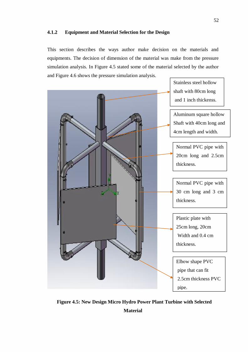
4.1.2 Equipment and Material Selection for the Design
This section describes the ways author make decision on the materials and
equipments. The decision of dimension of the material was make from the pressure
simulation analysis. In Figure 4.5 stated some of the material selected by the author
and Figure 4.6 shows the pressure simulation analysis.
Figure 4.5: New Design Micro Hydro Power Plant Turbine with Selected
Material
Stainless steel hollow
shaft with 80cm long
and 1 inch thickenss.
Aluminum square hollow
Shaft with 40cm long and
4cm length and width.
Normal PVC pipe with
20cm long and 2.5cm
thickness.
Normal PVC pipe with
30 cm long and 3 cm
thickness.
Plastic plate with
25cm long, 20cm
Width and 0.4 cm
thickness.
Elbow shape PVC
pipe that can fit
2.5cm thickness PVC
pipe.

53
Figure 4.6: Software Pressure Flow Analysis
The software pressure flow analysis shows that the flow rate was reduced
when it crossed the turbine as indicate in green colour. However, the flow rate was
higher when the flow does not touch the turbine as indicate in the Figure 4.6.
According to the energy conservation law, the energy can neither be created nor
destroyed: it can only be transformed from one state to another. Hence from the
analysis in Figure 4.6, the energy of the water flow reduce when cross over the
turbine and this caused a pressure impact on the turbine increase. Consequently, the
turbine can turn. Hence, the material that selected for this part has to suit the
equipment, so that the turbine can sustain the flow and work well.
Firstly, the drive shaft is the main support and carries the blades of the new
design turbine. Hence, it is an importance part. A stainless steel hollow shaft was
chosen by the author because this material is lighter in weight as it is hollow if
compare with a non-hollow shaft. Besides, a stainless steel material was chosen by
the author because this material will not out of shape and can sustain a high pressure
head flow. Moreover, this kind of material will not rust if compare with a steel
material that will rust very fast if contact with water and this will cause the failure for
the micro hydro power plant to generate electricity. Besides, a square aluminium

54
hollow shaft was added to hold all the 4 blade of the turbine. This material was
chosen because it is light in weight and prevents rust when contact with water, but
this material was not able to sustain a high head flow like the stainless steel.
However, when this material is joining together with the stainless steel, it will be
able to sustain a high head flow.
Second, the turbine blades will be the part that contacts the most with the
water so that it can provide a reaction to generate electricity. All plastic material was
chosen so that avoiding too much additional weight as they would in turn increase
their inertia. All these parts were joined together with bolt, nuts and also washer. The
screw pick will be according to the hardness and strength analysis that apply when
water flow head hit on it. The bigger force the turbine sustains the bigger screw the
area will need. But for other places, the author will pick the screws to as small as
possible to reduce the weight.
Third is the supporting framework, this part will fully depend on the turbine
and the environment itself. A wider river will need a longer and bigger support to
carry the turbine.. During the building process, a bigger bolt, nut and washer will be
preferred to provide a better and stronger support.
4.1.3 Troubleshooting on the Design
When first the author implements the new design into the water and the author found
that the turbine is hardly move due to few problems.
The first was the material selection that causes a heavy weight, the blade
holder down PVC pipe which is submarine in the water has trap a lot of water inside
it and this indirectly has increase the weight of the turbine where it has to bring along
the water to go round with the turbine. This has increase the inertia force. This is
different from the simulation; the water will not go into the pipe in the software
simulation. Hence the author drill holes at the water submarine pipe to reduce the
weight of the turbine. This has indicated in the previous Figure 3.15. Besides, the

55
generator of the new design is giving a non-constant output voltage. This has
influence the output reading. To solve this problem, the author has change the
generator to a more stable generator as in Figure 3.16.
The second problem arises on the alignment problem as indicate in the Figure
4.7. This problem arises when the head of the flow is too high where only one
bearing design was unable to sustain the high head flow. Hence this problem has
been solved by the author with adding an extra bearing into the design to support the
structure. Besides, the gear system has been removed and replace with the direct
coupling system to solve this problem as well like indicate in the Figure 3.17. Hence,
all these improvement has result in the new prototype as indicated in Figure 3.18.
The new prototype will have a lighter weight and small inertia. Besides, it also has a
better alignment that can run smoother in the testing.
Figure 4.7: Bad Alignment of The First Prototype
The gear is totally
out of alignment
when the flow
head is too high.

56
4.1.4 Improved Design
The improvement of the prototype was highly increased the efficiency of the first
prototype. The first prototype always faces the alignment problem very seriously
where the turbine was only able to turn for a few rounds in a simple testing with
water jet spray on it. After that, the turbine was out off its alignment. This problem is
solved in the improved prototype. Besides, the weight of the first prototype was
heavier and holes drilling had solved the problem. Hence, the second prototype had
highly improved the first prototype.
4.2 Experiment 1 on the New Design: Depth Testing
The new design was put inside a water tank with different dept on the turbine blade
for testing as indicated in Figure 3.11, a high pressure water jet is use to test the
turbine. The testing method is shows in Figure 4.8. Table 4.1 will show the data
from 10cm depth of the blade in the water, and table 4.2 will shows the data from
3cm depth of the blade in the water.
Table 4.1: Data of 10cm dept of the blade in the water
Number Voltage obtained (V)
1. 1.26
2. 1.35
3. 1.29
Average 1.30
Table 4.2: Data of 3cm dept of the blade in the water
Number Voltage obtained (V)
1 2.04
2 1.99
3 1.98
Average 2.00

57
Figure 4.8: Water Tank Testing
4.2.1 Discussion on the experiment 1
By comparing the 2 different depths that use for the testing, the author found that the
3cm blade depth in water generate more voltage than the 10cm blade depth. This is
because there is more force that the turbine needs to over come on pushing the water
when a larger part of turbine blade is inside the water. Hence the 3cm depth gives a
larger average voltage of 2.00V than 10cm depth with 1.30V. Besides, the author
has found out that the minimum depth that the turbine can function well is 3cm depth
inside the water. If the blade was place higher than 3cm, the turbine was not able to
function properly. Besides, the author has notice that some energy had lost during the
closing of the functioning blade as indicated in Figure 4.9. This is one of the
disadvantages of the design. From this test, the author concluded that the lesser the
turbine blade inside the water, the higher the efficiency but the maximum was only
3cm depth into the water.

58
Figure 4.9: Closing Process of the Functioning Blade
4.3 Experiment 2 on the New Turbine: Different Kind of Flow
This test will carried out with different kind of flow on the turbine. Testing was
carried out in a river and in a water tank (same procedure with experiment 1 for
water tank test). The experiment was carried out with the same depth of blade of 3cm
inside the water. The Figure 4.8 will shows the testing method on a tank and Figure
4.11 will shows a testing method in the river. Table 4.3 will showed data from
turbine testing in a river and a tank, Figure 4.10 will show the relationship between
the two flows.
Some energy was
wasted when the
closing process
of the
functioning blade
Flow
direction

59
Table 4.3: Data of testing in a water tank and river
Time
(s)
Voltage (V)
Tank River
0 0.00 0.00
0.2 0.02 0.20
0.4 0.20 0.90
0.6 0.50 0.88
0.8 0.70 0.99
1.0 1.20 0.10
1.2 1.50 0.35
1.4 2.04 0.65
1.6 1.99 0.98
1.8 1.98 0.40
Figure 4.10: Voltage Along Time at Different Flows

60
Figure 4.11: River Testing
4.3.1 Discussion on the Experiment 2
This experiment shows that the turbine be able to generate electricity in different
kind of flows. In a tank, there will be a circular flow as the water will turn insides the
tank. However in the river, there will be a horizontal constant flow from the water
fall or hill ahead.
There are advantages and disadvantages between these two kinds of flows.
The advantage of the turbine in river is that the turbine does not need much inertia
force at start to turn the turbine. As indicated in figure 4.10, time taken to reach the
maximum voltage gain for horizontal flow is much lesser than the circular flow.
While for circular flow, the inertia force is needed to spin the water in the tank. The
bigger the force when the tank is bigger hence will result in longer period in reaching
the stability state.
Mean while as for the horizontal river flow, the voltage will not be stable. As
indicated in figure 4.10, the river flow voltage goes very low due to the unstable turn
of the turbine. This was because the area of the non-functioning blade holder when it
reached the opposite side of the functioning blade was too big that blocked the
flowing water as indicated in figure 4.12. This big area will be an advantage when it

61
is at the functioning blade side that will creating a bigger area to turn the turbine, but
it will become a disadvantages when it reached the opposite side of the functioning
blade because it will blocked the flowing water and affected the turning of the
turbine as indicated in Figure 4.13. On the other hand, this problem did not occur in
the circular flow.
Besides, the average voltage had found out with few assumptions. The
average voltage has taken from each after constant flow for the tank test. As for the
river test, fluctuation was not taken into consideration as only the value from the
constant flow taken into consideration. Hence result in Table 4.4 of average voltage
for river and tank test.
Table 4.4: Average Voltage in a water tank and river
Number River Water Tank
1 0.90 2.04
2 0.88 1.99
3 0.99 1.98
Average 0.92 2.00
Hence form this experiment; the author found out that the new design was
able to function in both of the tested flow and they had their advantages and
disadvantages and the average voltage for river flow is 0.92V and tank flow is 2.00V
with few assumption considered.

62
Figure 4.12: Turbine Blade That Block Flow
Figure 4.13: Turbine Affection Theory
The area was too big and
blocked the flow water when
this blade was in the opposite
side of the functioning blade
The turbine holder in
this part was the
disadvantage while it
blocked the
flowing water and
the blocking force is
the biggest when it
reached the
direction
perpendicular with the
flow.
The big area of
turbine holder in
this section was an
advantage where
it helps to turn the
turbine with a
bigger area
provided.
Flow direction

63
4.4 Experiment 3 on the New Turbine: Different Medium
This section, the author tested the new design in the different medium. The turbine
was tested using with a high pressure water jet spray on the turbine blade which was
placed without any contact with water. The experiment was tested with vertical and
horizontal placement of turbine as indicated in Figure 4.14 and Figure 4.15 and the
result was shown in table 4.5.
Table 4.5: Data of testing in air medium with vertical and horizontal position of
turbine,
Voltage, V (V)
Number Vertical Test Horizontal Test
1 5.88 0.08
2 5.79 0.06
3 5.81 0.09
Average 5.83 0.08
Figure 4.14: Vertical Position Turbine

64
Figure 4.15: Horizontal Position Turbine
4.4.1 Discussion on the Experiment 3
This test was run out to test the new design in a different medium which is in the air.
This test has shows that the new design can function in the air medium vertical
position well. There is no force needed to push the water like in the experiment 1.
However, the turbine worked not smoothly in the horizontal position.
In the vertical position, the test was carried out with the position of all the
blades facing in to the central drive shaft then the water will be spray out to it on the
functioning blade. The spraying direction needed to change when the blades swung
out. The blades will then all open up facing out of the shaft after few turn. This
process has decrease the inertia forces that needed to turn the turbine because with
the swinging blade weight had create a swinging force that reduce the inertia turning
force of the turbine. Hence, this increased the efficiency.
While in the horizontal position, the test was carried out with the position of
all the blades facing down the floor. Then the water will be spray on the function

65
blade. The function blade turned around and face back to the floor after pass through
the spraying water. This swinging blade process had benefited the vertical position
turbine but not the horizontal position turbine. This swinging force had slow down
and interrupts the turbine turning process of the horizontal position turbine. Hence,
reduced the efficiency.
Besides, with idea of portable, when running the experiment, the blade has to
be fixed tightly to prevent it dropped and disassembled from the turbine.
From this test, the author had found out that the average voltage for the
vertical position test was 5.83V and the horizontal test was 0.08V. Hence, vertical
position turbine produced higher efficiency than the horizontal position turbine.
Besides, this method shows that in different medium, the efficiency of the turbine
was different and in air medium the turbine was having the highest efficiency if
compare to other medium like water in experiment 2.
4.5 Experiment 4 on the New Turbine: Impedance Matching Test
The impedance matching test was a test that the author applied some loads like
resistor to the turbine for testing. This test is to obtain the suitable resistance value
that fixed the impedance matching. This test was tested on the most efficiency
method (air medium horizontal position of the turbine). Besides, the power was
obtain from test in the first section (Table 4.6,4.7,4.8,4.9 and 4.10) as well as the
relationship was shown in the graphs in the second section (Table 4.11, 4.12,4.13 and
Figure 4.16,4.17,4.18).

66
4.5.1 Result from load test
Load = 10 ohms Resistor
Table 4.6: Result computation for 10 ohms Resistor
No. Voltage, V
(V)
Current, I
(mA)
1 0.55 55.00
2 0.60 60.00
3 0.59 59.00
Average 0.58 58.00
Power, P = VI
= (0.58) (58.00m)
= 33.64mW
Load = 50 ohms Resistor
Table 4.7: Result computation for 50 ohms Resistor
No. Voltage, V
(V)
Current, I
(mA)
1 1.77 35.4
2 1.69 33.8
3 1.73 34.6
Average 1.73 34.6
Power, P = VI
= (1.73)(34.6m)
= 59.85mW

67
Load = 100 ohms Resistor
Table 4.8: Result computation for 100 ohms Resistor
No. Voltage, V
(V)
Current, I
(mA)
1 2.31 23.1
2 2.22 22.2
3 2.28 22.8
Average 2.27 22.7
Power, P = VI
= (2.27)(22.7m)
= 51.53mW
Load = 150 ohms Resistor
Table 4.9: Result computation for 150 ohms Resistor
No. Voltage, V
(V)
Current, I
(mA)
1 2.54 16.9
2 2.59 17.27
3 2.45 16.33
Average 2.53 16.80
Power, P = VI
= (2.53)(16.8m)
= 42.50mW

68
Load = 200 ohms Resistor
Table 4.10: Result computation for 200 ohms Resistor
No. Voltage, V
(V)
Current, I
(mA)
1 3.11 15.50
2 2.92 14.60
3 2.82 14.10
Average 2.95 14.80
Power, P=VI
= (2.95)(14.8m)
= 43.66mW
4.5.2 Relationship between the gained results
Voltage and Resistance Value
Table 4.11: Voltage and Resistance Value
Resistor, R (Ohms) Voltage, V (V)
10 0.58
50 1.73
100 2.27
150 2.53
200 2.95

69
Graph of Voltage versus Resistance
0
0.5
1
1.5
2
2.5
3
3.5
0 50 100 150 200 250
Resistance(ohms)
Vo
ltag
e(V
)
Figure 4.16: Graph of Voltage versus Resistance
Current and resistance value
Table 4.12: Current and Resistance Value
Resistor, R (Ohms) Current, I (mA)
10 58.0
50 24.6
100 22.7
150 16.8
200 14.8

70
Graph of the Current Versus Resistance
0
0.01
0.02
0.03
0.04
0.05
0.06
0.07
0 50 100 150 200 250
Resistance(ohms)
Cu
rren
t(A
)
Figure 4.17: Graph of Current versus Resistance
Power and resistor value
Table 4.13: Power and Resistance Value
Resistor, R (Ohms) Power, P (mW)
10 22.64
50 59.85
100 51.53
150 42.50
200 43.66

71
Graph of Power Versus Resistance
0
0.01
0.02
0.03
0.04
0.05
0.06
0.07
0 50 100 150 200 250
Resistance(ohms)
Po
wer(
W)
Figure 4.18: Graph of Power versus Resistance
4.5.3 Discussion on experiment 4
From the figure 4.16, the graph Voltage versus Resistance, the author observes that
the voltage is increasing when the resistance value is increasing but not with a
constant straight line. In theoretical, the graph should be linear according to Ohms
law; Equation 4.1. This might cause by the unstable rotating during the test. The
author observed that the whole system was vibrating (only little vibration) and this
will affect the turning of the turbine and hence resulted in this section. Besides, the
friction from the bearing was not the same because the friction became bigger with
turning. The lubricant inside the bearing became lesser and different amount was
added into it.
Form the Figure 4.17, the graph of the Current versus Resistance; the author
observes that the current value decreased with increased resistance value. According
to Ohm law the relation between current and resistance was inversed. The shape of
the graph was smooth and only small amount of significant change and this was
cause by the same problem as discuss about by the voltage versus resistance
relationship.

72
The power has an equation as indicate in equation 4.2. According to the
experiment, the highest output was 59.85mW with 50 ohm resistor. The non
consistence of the value from this part was caused by the turning vibration effect.
V=IR (4.1)
where
V= Voltage , V
I= current, A
R= resistance, Ω
P = IV (4.2)
P= Power, W
I=current, A
V=voltage, V
4.6 Efficiency Calculation
The efficiency can be calculated by the equation 4.3
η = Pout / Pin * 100% (4.3)
where
η = efficiency, %
Pout = output power; W
Pin = input power; W
The input power can calculated from the formula as below:

73
Power input = Head x Flow x Gravity (4.4)
where
Power input = power input; W
Head = head of water; m
Flow = input flow rate; l/s
Gravity = gravitational force; m/s*s
For this experiment, the author is using a high pressure water jet that has it flow rate
stated by the manufacturer. This value was 340 l/h, and this is equal to 0.94444 l/s.
the head in this experiment was defined as 0.2m and gravity was 9.81 m/s*s.
With the equation 4.2, power input was calculated as 0.1853 W.
Power input = (0.2) x (0.09444) x (9.81)
= 0.1853 W
For power output is 59.85mW which is the highest power value achieved in the
experiment 4
Efficiency = (59.85m/0.1853) x 100%
= 32.30%
Hence, the efficiency for the new turbine is 32.30% as tested in the vertical position
of the turbine place in the air medium.

CHAPTER 5
5 CONCLUSION AND RECOMMENDATIONS
5.1 Overall Conclusion
The objective of this project was achieved. A new cost effective micro hydropower
prototype which was able to generate electricity for basic use is built. With the
unique design of this hydropower turbine, it is able to generate electricity in different
kind of places; the most effective generation was the vertical position of the turbine
in air medium. The merit of this design is the flexible blade as the non-functioning
blades will follow the flow of the water or air, thus increasing the efficiency of the
machine.
Beside, with the portable idea of this turbine, it was able to mobile to
different places for electricity generation as this point brings convenience to the user.
When finish using, the blade can be depart from the turbine as the perpendicular to
the drive shaft blade holder can be bend up to the same direction with the drive shaft
as shows in figure 5.1. This will reduce the area space when travel. Hence, this
design is convenience to mobile.
This design has many advantages over other methods of hydroelectric power
production. For example, it is quiet when operating compared to conventional
waterwheel. Besides, the portable idea of this machine has leaded it to be easy to
transport and install. Moreover, this design is environmentally friendly. This design
is also cost effective while it uses all inexpensive material and also this design does
not significantly interrupt the river flow.

75
Figure 5.1: Portable Turbine
Besides this, through the involvement on this project. The author had realized
the importance of green energy that deal with the environment impact issues of the
world today. Micro hydropower project also able to open new markets related to the
marginal hydro potential and improve the rehabilitation on the hydropower research
for further development.
5.2 Project Achievement
The new design of the author has efficiency of 32.30% overall. With this new idea,
user will be able to mobile to different hydro places to generate electricity. Besides,
the most importance point of this idea was eco-friendly usage with no environment
harmful item produced.

76
5.3 Recommendation and Future Work
There are advantages and disadvantages of the author new design that affect the
efficiency of the electricity generation. There are few recommendations that can
improve to this design:
A smaller dimension of turbine blade holder that can increase the efficiency.
While this will decrease the blocking force from the river flow when this
design is apply to river to generate electricity.
A suitable thickness of aluminium blades can be replace by the plastic blade
because it easy to create a more suitable degree of angle blade to increase the
efficiency.
Besides, with the improvement, this design will perform better.
Recommendation on application like this micro deigns will possibility is able to
replace the big dam needed hydropower design after some adjustment of design.
With many of this designs place across the flowing river, it will be able to generate
electricity and do not need a dam. Hence, it is more eco-friendly to the nature.
Besides, it also will be able to help some rural area citizen to generate light in the
dark.
77
REFERENCES
Baumann, S., Beatty, C., Brownell, S., Constant, A., Coons, J., Fisher, D., Lazar, B.,
& Yonkelowitz. W. (2010). Intermediate Energy Infobook. Rockford, MI: Need,
National Energy Education Development.
Bockman, T., Fleten, S. E., Juluissen, E., Langhammer, H. J., & Revdal, I. (2007).
Investment Timing and Optimal Capacity Choice for Small Hydropower Project.
European Journal of Operational Research 190 , 255-267.
Hydroelectric Power. (July 2005). U.S. Department of the Inrerior Bureau of
Reclamation Power Resources Office.
Hydropower Energy Technologies Worldwide. (October 2009). Large, Small,
Mini,micro and pico. report linker, SBI. Retrieved August 29, 2010 from
http://www.reportlinker.com/p0154015/Hydropower-Energy-Technologies-
Worldwide-Large-Small-Mini-Micro-and-Pico.html.
John, S., & Anagnostopoulos, A. D. (2007). Flow Modeling and Runner Design
Optimization in turgo Water Turbines. World Academy of Science, Engineering
and Technology .
Jones, Z. (2005). Domestic electricity generation using waterwheel on moored barge.
Meng in Structural Engineering with International Studies .
Madamombe, I. (2005). Energy key to Africa's prosperity,Challenges in West
Africa's quest for electricity. Africa Renewal.
Micro-Hydropower System; A Buyer's Guide. (2004). Canada: Natural Resources
Canada.
Mohibullah, Hakim, M. A., & Abdul, M. I. (2004). Basic Design Aspects of Micro
Hydro Power Plant. Nationai Power & Energy Conference (PECon) 2004
Proceedings, Kuala Lumpur, Malaysia , 220.
Norman, J. (2003). welcome to the world of hydropower. Retrieved September 6,
2010, from http://www.tande.com.tw/rn-hydro/alaskan.pdf.

78
Rasi, D. a. (2008). On the use of a laboratory-scale Pelton wheel turbine in
renewable energy education. Renewable Energy , 1517-1522.
Saket, D. R. (2008). Design, Development and Reliability Evaluation of Micro
Hydro Power Generation System Based on Municipal Waste Water. IEEE
Electrical Power & Energy Conference , 1-2.
Sale et al, M. J. (2008). Status of the U.S. Department of Energy's. U.S. Department
of Energy (DOE).
Stiesdal, H. (1999). The wind turbine components and operation. IEEE Transactions
on Energy Conversion .
The Star. (June 4, 2010). Hydropower more cost-effective than coal-fired plant, says
Utar study. Kota kinabalu: The Star.
Types of Hydropower Turbines. (2005). Retrieved July 2, 2010, from U.S
Department of Energy, Energy Efficiency and Renewable Energy .

79
APPENDICES
APPENDIX A: Gantt Chart

80

81
APPENDIX B: Generator Specification