provided for non-commercial research and educational use ...david/publis/review on lipid...
TRANSCRIPT

Provided for non-commercial research and educational use only. Not for reproduction, distribution or commercial use.
This chapter was originally published in the book Advances in Planar Lipid Bilayers and Liposomes, Vol. 14, published by Elsevier, and the attached copy is provided by Elsevier for the author's benefit and for the benefit of the author's institution, for non-commercial research and educational use including without limitation use in instruction at your institution, sending it to specific colleagues who know you, and providing a copy to your institution’s administrator.
All other uses, reproduction and distribution, including without limitation commercial reprints, selling or licensing copies or access, or posting on open internet sites, your personal or institution’s website or repository, are prohibited. For exceptions, permission may be sought for such use through Elsevier's permissions site at:
http://www.elsevier.com/locate/permissionusematerial
From: F. Ziebert and D. Lacoste, A Planar Lipid Bilayer in an Electric Field: Membrane Instability, Flow Field, and Electrical Impedance. In Aleš Iglič, editor:
Advances in Planar Lipid Bilayers and Liposomes, Vol. 14, Burlington: Academic Press, 2011, pp. 63-95.
ISBN: 978-0-12-387720-8 © Copyright 2011 Elsevier Inc.
Academic Press.

Author's personal copy
C H A P T E R T H R E E
A
IS
1
2
3
*
dvance
SN 1
LaborParis,PhysiInstit
CorreE-ma
A Planar Lipid Bilayer in an ElectricField: Membrane Instability, FlowField, and Electrical Impedance
F. Ziebert1,2,3 and D. Lacoste1,*
Contents
1. In
s in
554
atoFrakaliut C
spoil ad
troduction
Planar Lipid Bilayers and Liposomes, Volume 14 # 2011
-4516, DOI: 10.1016/B978-0-12-387720-8.00003-0 All rig
ire de Physico-Chimie Theorique - UMR CNRS Gulliver 7083, ESPCI, 10 ruencesches Institut, Albert-Ludwigs-Universitat, Freiburg, Germanyharles Sadron, 23 rue du Loess, Strasbourg, France
nding author. Tel.: þ33-140-795140; Fax: þ33-140-794731.dress: [email protected]
Else
hts
V
64
1
.1. M embranes in Externally Applied Electric Fields 641
.2. M embranes in Self-generated Electric Fields 652. A
Quasi-Planar Membrane in a DC Electric Field 662
.1. M odel Equations: Electrostatics 672
.2. M odel Equations: Hydrodynamics and Force Balance atthe Membrane
702
.3. G rowth Rate and Renormalized Elastic Moduli 712
.4. F low Fields Near a Driven Membrane 732
.5. A pplications to Specific Experiments 753. Im
pedance of a Planar Membrane in an AC Electric Field 763
.1. T ime-dependent Electric Fields 773
.2. E quations for Time-periodic Perturbations of an EquilibriumBase State
783
.3. Im pedance for an Ideally Blocking Non-conductive Membrane 793
.4. N on-conductive Membrane: Effect of UnequalDiffusion Coefficients
843
.5. Im pedance for an Ideally Non-blocking Conductive Membrane 884. C
onclusion 91Ackn
owledgments 92Refe
rences 93vier Inc.
reserved.
auquelin,
63

64 F. Ziebert and D. Lacoste
Author's personal copy
Abstract
For many biotechnological applications it would be useful to better understand
the effects produced by electric fields on lipid membranes. This review dis-
cusses several aspects of the electrostatic properties of a planar lipid mem-
brane with its surrounding electrolyte in a normal DC or AC electric field.
In the planar geometry, the analysis of electrokinetic equations can be carried
out quite far, allowing to characterize analytically the steady state and the
dynamics of the charge accumulation in the Debye layers, which results from
the application of the electric field. For a conductive membrane in an applied DC
electric field, we characterize the corrections to the elastic moduli, the appear-
ance of a membrane undulation instability and the associated flows which are
built up near the membrane. For a membrane in an applied AC electric field, we
analytically derive the impedance from the underlying electrokinetic equations.
We discuss different relevant effects due to the membrane conductivity or due
to the bulk diffusion coefficients of the ions. Of particular interest is the case
where the membrane has selective conductivity for only one type of ion. These
results, and future extensions thereof, should be useful for the interpretation of
impedance spectroscopy data used to characterize, for example, ion channels
embedded in planar bilayers.
1. Introduction
Bilayer membranes formed from phospholipid molecules are an essen-tial component of the membranes of cells. The mechanical properties ofequilibrium membranes are characterized by two elastic moduli, the surfacetension and the curvature modulus [1], which typically depend on theelectrostatic properties of the membranes and its surroundings [2]. Under-standing how these properties are modified when the membrane is drivenout of equilibrium is a problem of considerable importance to the physics ofliving cells. A membrane can be driven out of equilibrium in many ways, forinstance by ion concentration gradients or by electric fields.
Quite generally one can distinguish between systems in which theelectric field is applied externally and systems which are able to self-generateelectric fields.
1.1. Membranes in Externally Applied Electric Fields
The external application of electric fields on lipid films is used to produceartificial vesicles (electroformation), as well as to create holes in the mem-brane (electroporation) [3]. Both processes are important for biotechnolog-ical applications and they are widely used experimentally. However, theyare still not well understood theoretically. The research on electroformationis motivated by the hope to produce artificial lipid vesicles in a controlled
A Planar Lipid Bilayer in an Electric Field 65
Author's personal copy
and simple way, which will be key to many biotechnological applications.Cell electroporation is a popular technology and biomedical applications ofin vivo cell electropermeabilization [4] are gaining momentum for drug andnucleic acids electrotransfer and for the destruction of tumor cells for cancertreatment [5].
In view of the importance of these applications, many research effortshave been devoted to study and understand deformations of giant unila-mellar vesicles (GUVs) due to the application of electric fields. In thepresence of an AC electric field, GUVs show a rich panel of possiblebehaviors and morphological transitions depending on experimental con-ditions—electric field frequency, conductivities of the medium and of themembrane, salt concentration, etc., [6,7]. A theoretical framework involv-ing hydrodynamics and a continuum mechanics description of the mem-brane has been developed, which accounts quantitatively for the observedequilibrium and nonequilibrium shapes taken by the vesicles in the presenceof an AC electric field [8,9]. For a clear and self-contained presentation ofthis theoretical framework, we recommend the chapter “Non-equilibriumdynamics of lipid membranes: deformation and stability in electric fields” byP. Vlahovska [53].
The application of external fields is also interesting as a means to movefluids via electro-osmosis [10,11] and to self-assemble colloidal particles, forvarious technological applications. Moreover, the ability to move fluids andnanoparticles at small scales is used in many biological systems. For instance,membrane-bound ion pumps and channels are able to transport water (forinstance in aquaporin channels) and ions (in ionic pumps and channels) in aparticularly selective and efficient way, which one would like to reproducein artificial or biomimetic microfluidic devices.
1.2. Membranes in Self-generated Electric Fields
In some cases of biological relevance, membranes are able to self-generatean electric field, due to embedded ion channels or pumps. This can beachieved because the channels are able to transport ions from one side of themembrane to the other in a selective way, either down their concentrationgradient in passive transport or against it in active transport, for example,coupled to the hydrolysis of Adenosine triphosphate or activated by light.Probably the best known example is the opening and closing of ion channelsin nerve cells allowing the transmission of an electric signal via actionpotentials [12]. For all these reasons, ion channels and pumps play anessential role in many biological functions of a cell [13].
In order to better understand how nerve cells operate in vivo, it would behelpful to construct an in vitro biomimetic equivalent which would havesome key features of the in vivo system, such as the ability to generate anaction potential, but without the complexity of a real nerve cell. Active

66 F. Ziebert and D. Lacoste
Author's personal copy
membranes, which are GUVs containing ion pumps such as bacteriorho-dopsin [14–16] are a promising system to achieve this goal.
The main purpose of this review is to propose and analyze a simplemodel to foster the understanding of various effects resulting from electricfields acting on a planar lipid membrane. Although we are mostly interestedin applications to biological or biomimetic systems composed of lipidmembranes, we would like to point out that the theoretical frameworkpresented here is very general. It can be easily adapted to analyze theelectrical properties of artificial membranes which can have very differentproperties from biological membranes (as far as, e.g., ionic conductivities orthe bending stiffness are concerned).
This review is organized as follows: in Section 2 we present the modelfor a planar lipid membrane and its surrounding fluid in an applied electricfield. In this section, we will restrict ourselves to the case of a DC field.In particular we will focus on (i) the electrostatic and electrokinetic steady-state corrections to the elastic moduli of the membrane due to the applica-tion of the electric field, see Section 2.3; (ii) the flow fields which can bepredicted from such an approach, at steady state and in the case that themembrane is ion-conductive, see Section 2.4. In Section 2.5 we willcompare the model predictions to two relevant experiments. More detailson this theoretical framework, as well as an extension to the nonlinearelectrostatic regime using the Poisson–Boltzmann (PB) equation, canbe found in Refs. [17–20]. Finally, in Section 3 we present an analysis ofthe model in the presence of time-dependent AC electric fields. We providederivations for the impedance of the system from the underlying electroki-netic equations, for situations where the membrane is either blocking orselectively conductive for ions.
2. A Quasi-Planar Membrane in a DCElectric Field
The mechanical properties of membranes at equilibrium are charac-terized by two elastic moduli, the surface tension and the bending modulus.These moduli typically depend on electrostatic properties, and their mod-ifications in the case of charged membranes or surfaces in an electrolyte havebeen examined theoretically in various situations: in the linearized Debye–Huckel approximation as well as in the nonlinear PB regime, for lipidmonolayers and symmetric bilayers [2,21–23]. More recently, chargedasymmetric bilayers with unequal Debye lengths on both sides of themembrane [24] and an uncharged membrane in a DC field [25] havebeen investigated.

A Planar Lipid Bilayer in an Electric Field 67
Author's personal copy
In all the works mentioned above, a free energy approach has been used.Note that while this method works well for equilibrium membranes, it isnot applicable to situations in which the membrane fluctuations have anonequilibrium origin, as in the case of active membranes containing ionchannels [14,15,26,27] or in the case of a membrane in a time-dependentelectric field. In our recent work [17–20], we thus have studied this problemusing an electrokinetic approach, which does not have the limitations of afree energy formulation. In this framework we allow for a finite conductiv-ity of the membrane due to, for example, ion channels or pumps, and theion transport is described using a Poisson–Nernst-Planck (PNP) approach[28–30]. The electrostatic corrections to the elastic moduli and the fluidflows in the electrolyte are then obtained by imposing the overall forcebalance at the membrane.
Two additional points are worth emphasizing: first, our approach is ableto correctly describe the capacitive effects of the membrane and of theDebye layers while keeping the simplicity of the “zero-thickness approxi-mation” on which most of the literature on lipid membranes is based. This isaccomplished by the use of an effective Robin-type boundary condition(BC) at the membrane. Second, as the method is based on a calculation ofthe general force balance at the membrane, additional nonequilibriumprocesses could be included into the model rather easily. For simplicitywe investigate here only the effects of ionic currents flowing through themembrane, which in turn affect the fluid flow near the membrane. Othernonequilibrium effects that could be included as well are for instance ionchannel stochasticity or active pumping.
2.1. Model Equations: Electrostatics
Figure 1 shows a sketch of the planar geometry that is studied: we consider asteady current driven by a DC voltage drop V across two electrodesseparated by a fixed distance L. The membrane is quasi-planar and locatedat z ¼ 0. It is embedded in an electrolyte of monovalent ions with numberdensities nþ and n�. It contains channels for both ion species but is itselfneutral, that is, does not carry fixed charges. The channels or pumps areassumed to be homogeneously distributed in the membrane and enter onlyin the effective conductance G, as introduced below. A point in themembrane is characterized in the Monge representation by the heightfunction h(r?), where r? is a two-dimensional in-plane vector. The basestate of this problem is a flat membrane. Hence the electric field, assumed tobe perfectly aligned in z-direction, is perpendicular to it. We assume aquasi-static approach [18,25] in which membrane fluctuations are muchslower than the characteristic diffusion time t ¼ 1/Dk2 for the ions todiffuse a Debye length.

+
+
+
+
+
+
−
−
−
−
−
−
−
−
+
−
+
+
−V/2 V/2
–L/2–L/2 0
Figure 1 Sketch of a quasi-planar membrane embedded in a symmetric electrolyte.The initially flat bilayer membrane is represented by the plane z ¼ 0. The membranefluctuations around this base state have not been represented. A voltage�V/2 is appliedon each electrode, which are separated by a distance L. The membrane carries ionchannels which give rise to a conductance G.
68 F. Ziebert and D. Lacoste
Author's personal copy
In the electrolyte, the electric potential f obeys Poisson’s equation
r2f ¼ � 1
eenþ � en�ð Þ ¼ � 2
er: ð1Þ
Here e is the elementary charge, e is the dielectric constant of the electrolyteand we have introduced half of the charge density,
r ¼ enþ � n�
2: ð2Þ
For the sake of simplicity, we assumed a symmetric 1:1 electrolyte, thus faraway from the membrane nþ ¼ n� ¼ n*, and the total system is electricallyneutral. The densities of the ion species obey the PNP equations
@tn� þr � j� ¼ 0; j� ¼ D �rn� � n�
e
kBΤrf
� �; ð3Þ
where j� are the particle current densities of the ions and kBT is the thermalenergy. We will assume here that both ion types have the same diffusioncoefficient D. Note that we will discuss the effects of differing diffusioncoefficients for an applied AC voltage in Section 3.4.

A Planar Lipid Bilayer in an Electric Field 69
Author's personal copy
Since we are primarily interested in the behavior close to the membrane,for the BCs far away from the membrane we assume
f z ¼ �L=2ð Þ ¼ �V=2; ð4Þr z ¼ �L=2ð Þ ¼ 0: ð5Þ
Equation (4) states that the potential at the electrodes is held fixed exter-
nally. This BC is quite oversimplified for real electrodes, but captures themain effects of the electric field, see the discussion in Ref. [19]. We havealso assumed that the distance between the electrodes is much larger thanthe Debye length, L � lD ¼ k�1, wherek ¼ffiffiffiffiffiffiffiffiffiffiffi2e2n�
ekBT
s¼ l�1
D : ð6Þ
Hence, as already mentioned above, the bulk electrolyte is quasi-neutralwith negligible charge density (compared to the total salt concentration) andfar from the membrane Eq. (5) holds.
The BC at the membrane is crucial to correctly account for capacitiveeffects. We use the Robin-type BC (see Appendix for a derivation)
lm n�rð Þfjz¼ hþ ¼ lm n�rð Þfjz¼h� ¼ f hþð Þ � f h�ð Þ; ð7Þ
where n is the unit vector normal to the membrane and
lm ¼ eem
d: ð8Þ
lm is a length scale containing the membrane thickness d and the ratio of thedielectric constants e/em of the electrolyte and the membrane. Note that inEq. (7), the membrane plays a similar role as the Stern layer in the descrip-tion of Debye layers near a charged interface. This BC was rederived forelectrodes sustaining Faradaic current [31,32] or charging capacitively [33],and was applied for membranes in Refs. [18,19,30]. There it was shown toproperly account for the jump in the charge distribution which occurs nearthe membrane as a result of the dielectric mismatch between the membraneand the surrounding electrolyte.
In addition to Eq. (7), we impose the continuity of the bulk currentjjz ¼ 0r at the membrane. This BC involves the ohmic law
jrjz¼ 0
¼ �G
emr½ �z¼ 0 ; ð9Þ

70 F. Ziebert and D. Lacoste
Author's personal copy
where G denotes the membrane conductance per area and mr the electro-chemical potential. The electrostatic potential and the ion densities can nowbe obtained by solving Eqs. (1, 2) in the linear Debye–Huckel approxima-tion and one obtains [19]:
(i) the jump of the charge density at the membrane, rm,(ii) the current through the membrane, jm, and(iii) the electric field inside the membrane, E0
m:
rm ¼ ek2=2ð ÞV � jm=Dð Þ L þ lmð Þ2þ klm
; ð10Þ
jm ¼ �jr ¼ GV
1þ 2=ek2Dð ÞGL; ð11Þ
� �� �
Em0 ¼ � 1d
2
ek2� jmL
D� 2rm þ V : ð12Þ
For simplicity, in the derivation of Eqs. (10)–(12) we assumed equal ionconductivities (Gþ ¼ G� ¼ G) and a symmetric electrolyte on both sidesof the membrane (k>0 ¼ k<0 ¼ k). Note that the method presented in thissection can be easily extended to cover more general cases. In addition, thenonlinear electrostatic problem (keeping the PB equation) can be still solvedanalytically in the non-conductive case. The nonlinear generalizations ofEqs. (10)–(12) can be found in Ref. [20].
2.2. Model Equations: Hydrodynamics and Force Balance atthe Membrane
The hydrodynamics of the electrolyte is described by the incompressibleStokes equation, �rp þ �r2v þ f ¼ 0 with r � v ¼ 0, where v is thevelocity field of the electrolyte, � its viscosity, p the hydrostatic pressure andf ¼ �2rrf the electric driving force. From the solution of the electro-static and the hydrodynamic problem, one obtains the total stress tensor
tij ¼ �pdij þ � @ivj þ @jvj� �þ e EiEj � 1
2dijE2
� �; ð13Þ
which contains the pressure, the viscous stresses in the fluid and theMaxwell stresses.
The lipid bilayer membrane, on the other hand, behaves as a two-dimensional fluid which can store elastic energy in bending deformations.

A Planar Lipid Bilayer in an Electric Field 71
Author's personal copy
More precisely, its elastic properties can be described by the standardHelfrich free energy
FH ¼ 1
2
ðd2r? S0 rhð Þ2 þ K0 r2h
� �2h i; ð14Þ
where S0 is the bare surface tension andK0 the bare bending modulus of themembrane.
All forces present in the system, the electrostatic, viscous, and elasticones, have to fulfill the force balance equation. The latter states that thediscontinuity of the normal–normal component of the stress tensor, asdefined in Eq. (13) and evaluated at the membrane position, must equalthe restoring force due to membrane elasticity, hence
� tz z;1jz¼hþ � tzz;1jz¼h�� � ¼ � @FH
@h r?ð Þ ¼ �S0k2? � K0k
4?
� �h k?ð Þ� ð15Þ
Here the index 1 in the stress tensor refers to the order of an expansion withrespect to the membrane height field h(r?). Note that at zeroth order, themembrane is flat and thus only electric forces and osmotic pressure balance.By expanding to linear order in the height field h(r?), and using
h / h0eik?�r?þs k?ð Þt; ð16Þ
Equation (15) yields the growth rate s(k?) of membrane fluctuations.Details of the derivation of s(k?) can be found in Refs. [17–19]. Wewould like to emphasize that the force localized at the membrane surfaceis a priori unknown in this problem. Thus it must be determinedself-consistently from the BCs for the velocity and the stress.
2.3. Growth Rate and Renormalized Elastic Moduli
The force balance Eq. (15) determines the growth rate s(k?) entering thenormal stress difference,
�k?s k?ð Þ ¼ � 1
4S0 þ DSð Þk2? � Gkk
3? � 1
4K0 þ DKð Þk4?� ð17Þ
The electrostatic corrections to the surface tension, DS ¼ DSk þ DSm,and to the bending modulus, DK ¼ DKk þ DKm can be decomposed into:
(i) an outside contribution due to the charges accumulated in the Debyelayers and denoted with the index k;

72 F. Ziebert and D. Lacoste
Author's personal copy
(ii) an inside contribution due to the voltage drop at the membrane anddenoted with an index m. They are given by
DSk ¼ �4r2mek3
� 16rmjmek4D
; DKk ¼ 3r2mek5
ð18Þ
for the contribution due to the Debye layers and by
DSm ¼ �em Em0
� �2d; DKm ¼ em Em
0
� �2 d3
12� rmEm0
d
ek3
� �ð19Þ
for the contribution due to the field inside the membrane.Note that in Eq. (17), one also obtains a purely nonequilibrium correc-
tion Gk ¼ (4rmjm)/(ek5D). It would correspond to a term proportional to
k?3 in an “effective membrane free energy” incorporating the Maxwellstresses. At equilibrium such a term is forbidden by symmetry, but in anonequilibrium situation, where the membrane sustains a current jm 6¼ 0, itis allowed. For realistic parameters, however, this term is very small, seeRef. [18] for a detailed discussion.
The inside contribution to the membrane surface tension is alwaysnegative, see Eq. (19). The same is typically true for the outside contribu-tion, see Eq. (18) and note that rm, jm > 0. Hence these contributions canovercome the bare surface tension S0. If this is the case, an instabilitytowards membrane undulations sets in. Such an instability had alreadybeen described for the high salt limit in Ref. [34]. Note that the linearizedtheory developed here describes only the early stages of the instability, but itis more general than previous works since it is not limited to the high saltlimit and in addition accounts for hydrodynamic effects. The linear growthrate of the membrane fluctuations given by Eq. (17) is shown in Fig. 2 inrescaled units. We scaled the wave vector by k, hence k0 ¼ k?/k and thetime by the typical time for ions to diffuse a Debye length, t ¼ 1/Dk2. Thecontrol parameter of the instability is the external voltage V. Figure 2 showsthe growth rate for three different levels of the voltage: the dashed line is forV ¼ 0.7 V, which lies below the threshold of the instability, all wavenumbers are damped and the membrane is stable. The solid and the dash-dotted line correspond to V ¼ 0.75 and 0.8 V. These values are abovethreshold and the growth rate is positive for a finite wave number window.
For a more detailed discussion of the dependence of the corrections tothe elastic moduli, the instability threshold and the characteristic wavenumber as a function of salt concentration and membrane conductivity,we refer the reader to Refs. [18,19].

0 0.2 0.4 0.6 0.8 1
k¢
–4
–3
–2
–1
0
1
2
ts(k¢)
Figure 2 The renormalized growth rate or dispersion relation, ts, as a function of therescaled wave number k0 ¼ k?/k for three voltages: V ¼ 0.7 V (dashed line),V ¼ 0.75 V (solid line), and V ¼ 0.8 V (dash-dotted line).We have used the followingparameters: dielectric constants e ¼ 80e0 and em ¼ 2e0; membrane thickness d ¼ 5 nmleading to lm ¼ (e/em)d ¼ 200 nm; diffusion coefficient of ions D ¼ 10�9m2s�1; vis-cosity � ¼ 10�3 Pas; inverse Debye length k ¼ 2 107 m�1; bare surface tensionS0 ¼ 1 mN m�1; bare bending modulus K0 ¼ 10 kBT. Here we assumed a non-conductive membrane, G ¼ 0.
A Planar Lipid Bilayer in an Electric Field 73
Author's personal copy
2.4. Flow Fields Near a Driven Membrane
We now summarize the main features of the fluid flows which arise near themembrane when it is driven by ionic currents [18]. Figure 3 was generatedby selecting the fastest growing wave number and using the correspondingmaximum growth rate. The shape of the membrane undulation is repre-sented with the black solid curves. Figure 3C shows the flow field for a highmembrane conductance and low salt, in the regime where the membrane isunstable due to the electrostatic correction to the surface tension and thusstarts to undulate. The resulting flow is a superposition of two distinct flows:first, the typical flow associated to a membrane bending mode [35] as shownin Fig. 3A. Second, the flow which results from the ion transport across themembrane. The latter flow has the typical counter-rotating vortices of anICEO flow [36], as shown in Fig. 3B. Clearly, the superposition of thesetwo flow contributions, Fig. 3C, results in a parallel flow close to themembrane, in contrast to the usual bending mode flow given by Fig. 3A.

−5
0
5
10
15
z
−15 −10 −5 0 5 10 15x
−5
0
5
10
15
z
−5
0
5
10
15
z
B
C
A
Figure 3 Representation of the flows around the membrane beyond the instabilitythreshold. The orientation of the electric field is toward negative values of z. (A) showsthe flow generated by the membrane bending mode. (B) shows the ICEO flow. Finally,(C) shows the actual flow, which is the superposition of the former two and results in astrong flow near the membrane, oriented parallel to the surface. Both axes are scaled bythe Debye length k�1. Parameters are as in Fig. 2 except V ¼ 3.165 V, k ¼ 107 m�1,G ¼ 10 Sm�2 and L ¼ 10 mm.
74 F. Ziebert and D. Lacoste
Author's personal copy
For most realistic parameters—modest conductivities, not too low salt—the flow generated by membrane bending is usually dominating and hidesthe small ICEO contribution. To be able to observe the flows of Fig. 3, ahigh membrane conductance G and low salt are needed. Also, since formacroscopic electrode distances L (e.g., of the order of millimeters), thevoltage needed to induce the instability is very high, we have assumed amicroscopic electrode distance of L ¼ 10 mm. While it might still bepossible to observe flows for higher salt and macroscopic electrode

A Planar Lipid Bilayer in an Electric Field 75
Author's personal copy
separations, such situations cannot be analyzed within the Debye–Huckelapproximation used here.
Note that somewhat similar looking flow patterns have been recentlyobserved experimentally in vesicles subject to AC electric fields in Ref. [6].On closer inspection, however, it appears that these flows most probablyhave a different origin from the ICEO flows, since they are more likely toresult from electrophoresis of charged lipids within the membrane.
2.5. Applications to Specific Experiments
Here we will briefly discuss how the framework presented above can beapplied to recent experiments: the first experiment studied supportedmembranes subject to an electric field [37], while the second one investi-gated active membranes [14–16].
Lecuyer et al. [37] recently performed neutron reflectivity measurementson a system consisting of two nearby membrane bilayers in an external ACelectric field. One of the bilayers was close to the bottom electrode and usedto protect the second one from interacting with the wall. The bare values ofthe elastic moduli were known from X-ray off-specular experiments for asimilar system [38], yielding S0 ’ 0.5 mN m�1 and K0 ’ 15 kBT. Theexperiments were performed in an AC electric field at several frequencies.For the lowest frequency (10 Hz) and for a voltage of V ¼ 5 V, theelectrostatic corrections to the surface tension and bending modulus werefound to be DS ’ �1 � 0.15 mN m�1 and DK ’ 185 � 15 kBT.
Assuming that the membrane is non-conductive, G ¼ 0, and using aninverse Debye length of k ¼ 2 107 m�1 (milli-Q water) and the experi-mental electrode distance of L ¼ 1 mm, our model yieldsDS ’ �2 mN m�1 and DK ’ 190 kBT. Thus the model successfullyaccounts for the order of magnitude of the electrostatic corrections observedin this experiment. Note, however, that the linearized Debye–Huckelapproach is not a good approximation in this case, as applied voltagesare rather high. For this reason, we recently extended our work to thePB regime [20].
The second experiments we would like to discuss concerns activemembranes, which are artificial lipid vesicles containing bacteriorhodopsinionic pumps [14–16]. These pumps are able to transfer protons unidirec-tionally across the membrane by undergoing light-activated conformationalchanges. The transport of protons across the membrane eventually builds upa transmembrane potential. In Refs. [15,26,27], a hydrodynamic theory hasbeen developed to describe the nonequilibrium fluctuations of the mem-brane induced by the activity of the pumps. This work triggered substantialtheoretical interest in the problem, mainly focusing on the proper descrip-tion for these nonequilibrium effects associated with protein conformationalchanges [39–43].

76 F. Ziebert and D. Lacoste
Author's personal copy
In these models for active membranes, the electrostatic effects associatedwith the ion transport were not explicitly described. The framework pre-sented in this review provides a more detailed description of the iontransport, which could be useful to understand some aspects of activemembrane experiments. From a contour analysis of giant active vesicles,the fluctuation spectrum of the membrane was measured in Ref. [16], and alowering of the membrane tension produced by the activity of the pumpswas reported. Only the correction to the surface tension has been accuratelymeasured in this experiment and many aspects of the transport of ions arestill unknown. However, for simplicity we can assume that the passive statecorresponds to a non-conductive membrane,G ¼ 0, and the active state toa membrane with conductance G ¼ 10 Sm�2. If we also assume a typicaltransmembrane potential of the order of 50 mV, we can use the results forthe corrections to the surface tension obtained above. Accounting for therather high amount of salt using k ’ 5 108 m�1, we find a reasonableestimate for the observed tension lowering, DS ’ 3 10�7 Nm�1. Wealso find that there is no measurable difference for the bending modulusbetween the active and passive state, in agreement with the experiments.The model further predicts a current density of jm ’ 1 Am�2 when thepumps are active, which corresponds to an overall current of 1 pA on avesicle of size 1 mm.
This accord in orders of magnitude for the electrostatic corrections isquite promising. For a more detailed comparison between experiments andthe presented model, it would be necessary to do experiments in varyingconditions (ionic strength, conductance of the membrane, or orientation ofthe pumps in the membrane for instance). Combined measurements of themembrane current and the transmembrane potential in the same experi-ment, using, for example, patch-clamp techniques, would also be desirable.
3. Impedance of a Planar Membrane in anAC Electric Field
Impedance spectroscopy [44] is an effective tool to obtain a character-ization of the electric properties of lipid bilayer membranes. The methodhas been used in particular for supported lipid bilayers, which are apromising experimental system to characterize membrane proteins, chan-nels or inclusions and more generally constitute the basis of highly sensitivedetection technologies, that is, biosensors [45]. In the recent work [46], forinstance, impedance spectroscopy has been used to characterize gramicidinD channels in pore suspending membranes. Nowadays, many biotechnol-ogy companies develop systems to measure the impedance of whole cells forscreening or drug delivery.

A Planar Lipid Bilayer in an Electric Field 77
Author's personal copy
In many cases, the interpretation of the data obtained by impedancespectroscopy is not that straightforward. Typically one uses equivalentcircuits, which are sometimes controversial, since different models can beused for fitting the data. Moreover, there is often a lack of knowledgeconcerning the conditions of validity of these equivalent circuits to describethe diffuse charging in electric Debye layers. To answer these questions, onepossibility is to start with an electrokinetic description based on the PNPequations. With such an approach, the dynamics of diffuse charging [33]and the current–voltage relation in electrochemical thin films have beensuccessfully analyzed [32]. This approach is also useful for relating imped-ance measurements to the properties of the diffuse layers near chargeselective interfaces such as electrodes or ion-exchange membranes [47].
In the following, we extend the model studied in the previous sectionsto the case of an applied AC electric field. For simplicity the membrane willbe assumed to be strictly planar and non-fluctuating.We use the PNP equationsto evaluate the impedance of this system, which can be then compared tosimple equivalent circuits. We will first present the generic time-dependentequations for the perturbation induced by the applied AC field. Then weproceed to calculate the impedance for the following cases: (i) an ideallyblocking membrane with equal diffusion coefficients for the two ion spe-cies, (ii) the same system but with unequal ion diffusion coefficients andfinally (iii) an ideally non-blocking membrane which conducts selectivelyonly one type of ion.
3.1. Time-dependent Electric Fields
The PNP equations for an electrolyte have already been given inSection 2.1. Taking the time derivative of the Poisson equation, Eq. (1),one obtains
�e@tr2f ¼ e @tnþ � @tn
�ð Þ ¼ �e r � jþ � r � j�ð Þ; ð20Þ
where in the last equation, the conservation of ion densities, Eq. (3), hasbeen used. Through integration over space (assuming a one-dimensionalgeometry), and using the definition of the electric field, E ¼ �rf, itfollows that [48,49]
I ¼ e@tEþ eJ; ð21Þ
where the constant in of integration, I, is the total electric current density.The first term on the R.H.S in Eq. (21) is the displacement current. Thesecond term, J ¼ jþ � j� ¼ 2jr, is the particle current density. The dis-placement current was absent in the previous section because we assumed a

78 F. Ziebert and D. Lacoste
Author's personal copy
stationary state, but for the time-dependent case it is crucial to obtain theresponse to an externally applied AC electric potential. We note that byvirtue of the Poisson equation, Eq. (1), the total current density is diver-gence-free, r � I ¼ 0, at all times. Further note that the experimentallymeasurable quantity is given by the total electric current. For this reason, itis the relevant quantity to calculate the impedance as shown below.
3.2. Equations for Time-periodic Perturbations of anEquilibrium Base State
Let us assume an established equilibrium solution c0þ(z), c0
�(z) and f0(z) forthe electrolyte in the absence of the AC field, which could be caused by anadditional DC field or a Nernst potential. For convenience we considerhere the charge densities c�. Note that c� ¼ en� and k2 ¼ 2ec0/(ekBT). Theequations for the electrostatic problem, see Eqs. (1) and (3) above, read
e@2zf ¼ c� � cþ; ð22Þ@tc
� ¼ �@zj�; ð23Þ
� � � � e� �
j ¼ �D @zc � ckBΤ
@zf : ð24Þ
Linearization around the base state like
cþ ¼ cþ0 þ �Cþ; c� ¼ c�0 þ �C�; f ¼ f0 þ �F;
where � is a small book-keeping parameter, leads at order O(�0) to
c�0 ¼ c0e�ef0 zð Þ
kBT ; withf0 solution of e@2zf0 ¼ c0 ef0 � e�f0
� �:
This restates that the equilibrium solution has to fulfill the classical PBequation. At order O(�1) in the perturbations, we get
e@2zF ¼ C� � Cþ; ð25Þ
@tC� ¼ D�@z @zC
� � c�0e
kBΤ@zF� C� e
kBΤ@zf0
� �� ð26Þ
As already discussed in the general case above, taking the time derivativeof Eq. (25), insertion of the linearized PNP equations, Eq. (26), andintegration in z yields

A Planar Lipid Bilayer in an Electric Field 79
Author's personal copy
e@z@tF�D� @zC� � c�0
e
kBΤ@zF� C� e
kBΤ@zf0
!
þDþ @zCþ þ cþ0
e
kBT@zFþ Cþ e
kBΤ@zf0
!¼ I tð Þ:
The integration constant I(t) is the total electric current density. As weare interested in the response to an AC external voltage, V(t) ¼ V0e
iot,introducing I(t) ¼ I0e
iot and F / eiot, we arrive at
ioeþ e
kBΤDþcþ0 þD�c�0� � !
@zF
þDþ@zCþ �D�@zC� þ DþCþ þD�C�ð Þ e
kBΤ@zf0 ¼ I0:
ð27Þ
The first term on the L.H.S is the displacement current. The remainingterms are currents due to concentration gradients and a current induced bythe equilibrium potential at the membrane. All these contributions takentogether yield the total current I0 in response to the external AC field.
We are left with the problem to solve Eqs. (26) and (27) with theexternal voltage entering via the BC, just like in Section 2.
3.3. Impedance for an Ideally Blocking Non-conductiveMembrane
The equations derived in the last section are general as they describe the firstorder perturbation in an electrolyte induced by an AC voltage externallyimposed at some boundaries. Let us now apply them to the planar mem-brane geometry as sketched in Fig. 1. The membrane is assumed to be flatand located at z ¼ 0. The AC voltage will be externally applied at theelectrodes at z ¼ �L/2. For simplicity, we assume that there is no addi-tional DC electric field or Nernst potential, that is, that the equilibriumsolution is given by the homogeneous solution f0 ¼ 0, c0
þ ¼ c0.First we will treat the simplest case of an ideally blocking, non-conduc-
tive membrane, j�(0) ¼ 0. We also assume equal diffusion coefficients forthe positive and negative ions, Dþ ¼ D� ¼ D. Then the above Eqs. (26)and (27) for the perturbations reduce to
ioC� ¼ D@z @zC� � c0
e
kBT@zF
� �; ð28Þ
80 F. Ziebert and D. Lacoste
Author's personal copy
ioeþ 2Dc0e
kBΤ
� �@zFþD @zC
þ � @zC�ð Þ ¼ I0: ð29Þ
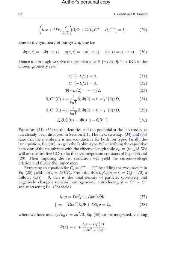
Due to the symmetry of our system, one has
F z; tð Þ ¼ �F �z; tð Þ; r z; tð Þ ¼ �r �z; tð Þ; c z; tð Þ ¼ c �z; tð Þ: ð30Þ
Hence it is enough to solve the problem in z 2 [�L/2,0]. The BCs in thechosen geometry read
Cþ �L=2ð Þ ¼ 0; ð31ÞC� �L=2ð Þ ¼ 0; ð32Þ
F �L=2ð Þ ¼ �V0=2; ð33Þ
@zCþ 0ð Þ þ c0e
@zF 0ð Þ ¼ 0 ¼ jþ 0ð Þ=D; ð34Þ
kBΤ@zC� 0ð Þ � c0
e
kBΤ@zF 0ð Þ ¼ 0 ¼ j� 0ð Þ=D; ð35Þ
lm@zF 0ð Þ ¼ F 0þð Þ � F 0�ð Þ: ð36Þ
Equations (31)–(33) fix the densities and the potential at the electrodes, ashas already been discussed in Section 2.1. The next two Eqs. (34) and (35)state that the membrane is non-conductive for both ion types. Finally thelast equation, Eq. (36), is again the Robin-type BC describing the capacitivebehavior of the membrane with the effective length scale lm ¼ (e/em)d. Wewill use the first five BCs to fix the five integration constants of Eqs. (28) and(29). Then imposing the last condition will yield the current–voltagerelation and finally the impedance.
Extracting an equation forCs ¼ Cþ þ C� by adding the two cases� inEq. (28) yields ioCs ¼ D@z
2Cs. From the BCs @zCs(0) ¼ 0 ¼ Cs(�1/2) itfollows Cs(z) ¼ 0, that is, the total density of particles (positively andnegatively charged) remains homogeneous. Introducing r ¼ Cþ � C�
and subtracting Eq. (28) yields
ior ¼ D@2zrþDek2@2
zF; ð37ÞioeþDek2� �
@zFþD@zr ¼ I0; ð38Þ2
where we have used c0e/kBT ¼ ek /2. Eq. (38) can be integrated, yieldingF zð Þ ¼ c1 þ I0z�Dr zð ÞDek2 þ ioe
:

A Planar Lipid Bilayer in an Electric Field 81
Author's personal copy
The BCs r(�L/2) ¼ 0, F(�L/2) ¼ �V0/2 fix the constant ofintegration to
c1 ¼ �V0
2þ I0L=2
Dek2 þ ioe:
Insertion of the obtained potential into Eq. (37) for r yields
Dk2 þ ioD
r ¼ @2zr: ð39Þ
Using again the obtained potential transforms theBC@zr(0) þ ek2 @zF(0)¼ 0 into the simpler form @zr(0) ¼ i(I0k
2/o). Together with r(�L/2) ¼ 0,the solution of Eq. (39) can be given as
r zð Þ ¼ iI0k2
bo cosh bL=2ð Þ sinh b zþ L=2ð Þ½ � ð40Þ
with the (complex) inverse length scale
b ¼ffiffiffiffiffiffiffiffiffiffiffiffiffiffiffiffiffiffiffiffiffiffiffik2 þ io=D:
pð41Þ
The remaining BC, Eq. (36), is a jump condition at the membrane.What we have calculated above are the solutions F<0, r<0 on z 2 [�L/2,0]. Using the symmetry of our problem, Eq. (30), one directly obtains F>0,r>0 on z 2 [0, L/2]. Imposing Eq. (36), lm@zF(0) ¼ F>0(0) � F<0(0),then yields
lmI0 �D@zr 0ð ÞDek2 þ ioe
¼ c>01 þ �Dr>0 0ð Þ
Dek2 þ ioe� c<0
1 þ �Dr<0 0ð ÞDek2 þ ioe
" #
¼ �2c<01 � 2
�Dr<0 0ð ÞDek2 þ ioe
:
Solving for the external voltage V0—note that it enters in the integrationconstant c1 of the electric potential—one gets
V0 ¼ I0L
Dek2 þ ioe� 2
Dr 0ð ÞDek2 þ ioe
þ lmI0 �D@zr 0ð ÞDek2 þ ioe
:
This is the current–voltage relation. The impedance is defined asZ(o) ¼ V(o)/AI(o) ¼ V0/(AI0), with A the membrane area normal to
:
82 F. Ziebert and D. Lacoste
Author's personal copy
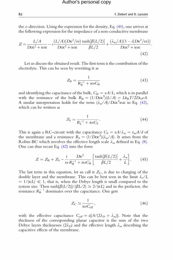
the z-direction. Using the expression for the density, Eq. (40), one arrives atthe following expression for the impedance of a non-conductive membrane
Z ¼ L=A
Dek2þ ioe� i
L=Að Þ Dk2=oð ÞDek2þ ioe
tanh b L=2ð Þ½ �bL=2
þ lm=Að Þ 1� i Dk2=oð Þð ÞDek2 þ ioe
ð42Þ
Let us discuss the obtained result. The first term is the contribution of theelectrolyte. This can be seen by rewriting it as
ZB ¼ 1
R�1B þ ioCB
ð43Þ
and identifying the capacitance of the bulk,CB ¼ eA/L, which is in parallelwith the resistance of the bulk RB ¼ (1/Dek2)(L/A) ¼ LkBT/2Dc0eA.A similar interpretation holds for the term (lm/A)/Dek2ioe in Eq. (42),which can be written as
ZS ¼ 1
R�1S þ ioCS
: ð44Þ
This is again a RC-circuit with the capacitance CS ¼ eA/lm ¼ emA/d ofthe membrane and a resistance RS ¼ (1/Dek2)(lm/A). It arises from theRobin-BC which involves the effective length scale lm defined in Eq. (8).One can thus recast Eq. (42) into the form
Z ¼ ZB þ ZS � i
oDk2
R�1B þ ioCB
tanh b L=2ð Þ½ �bL=2
þ lmL
� �: ð45Þ
The last term in this equation, let us call it ZC, is due to charging of thedouble layer and the membrane. This can be best seen in the limit lD/L¼ 1/(kL) 1, that is, when the Debye length is small compared to thesystem size. Then tanh[b(L/2)]/(bL/2) ’ 2/(kL) and in the prefactor, theresistance RB
� 1 dominates over the capacitance. One gets
ZC ’ 1
ioCeff
; ð46Þ
with the effective capacitance Ceff ¼ e[A/(2lD þ lm)]. Note that thethickness of the corresponding planar capacitor is the sum of the twoDebye layers thicknesses (2lD) and the effective length lm describing thecapacitive effects of the membrane.

RB
CB CS
Ceff
RS
Figure 4 Effective circuit for the ideally blocking non-conductive membrane,Eq. (47): Two RC-circuits, one for the bulk and one for the membrane are in serieswith the effective charging capacitance of the membrane.
A Planar Lipid Bilayer in an Electric Field 83
Author's personal copy
As shown in Fig. 4, for the blocking non-conductive membrane oneeffectively has an association in series of the RC-circuit of the bulk, theRC-circuit of the membrane and the effective capacitance of the chargingmembrane
Z ¼ ZB þ ZS þ ZC ¼ 1
R�1B þ ioCB
þ 1
R�1S þ ioCS
þ 1
ioCeff
; ð47Þ
as long as lD/L 1 holds. As lm ’ 200 nm, the impedance contributionZS is usually small compared to the bulk resistance and can be neglected forL � lm. However, the contribution described by lm to the chargingimpedance ZC can be of similar order as the one from the Debye layersand might even dominate the charging.
The best way to visually present the impedance is by a so-called Nyquistplot [44]. There one traces the negative imaginary part, �Im[Z(o)], of theimpedance as a function of its real part, Re[Z(o)], for varying frequency o.Nyquist plots for the full impedance, Eq. (45), and for the limit lD/L 1,Eq. (47), are shown in Fig. 5. Panel (A) shows the case of a macroscopicsystem size, L ¼ 1 mm. One clearly notices the RC-semi-circle terminat-ing for high frequencies at the origin. For the given parameters one entersthis semi-circle at o ’ 50 Hz; the maximum is achieved foroRC ¼ Dk2 ¼ 1 kHz. The low frequency branch is dominated by themembrane charging capacitively at R ’ RB þ RS, thus for low frequenciesone has a divergence like (ioCeff)
�1. As lD/L ’ 10�3, the effective circuitand the full calculation agree well.
Figure 5B shows the case of a microscopic system size, L ¼ 10 mm. Herethe bulk RC-signal is much less pronounced and charging dominatesentirely. The full calculation (solid curve) yields a lower resistance for thecharging process at low frequencies than the effective circuit obtained bythe small-Debye layer approximation (dashed curve).

0.0
Re (Z) [W]
0.0
6.0 × 10¹⁴
2.0 × 10¹⁴
1.5 × 10151.0 × 10155.0 × 1014
4.0 × 10¹⁴
8.0 × 10¹⁴–I
m (
Z)
[W]
A
Re (Z) [W]
0.0
1.0 × 10¹⁴
1.0 × 10¹³ 1.5 × 10135.0 × 1012
5.0 × 10¹³
–Im
(Z
) [W
]
B
Figure 5 (A) Shows a Nyquist plot for a macroscopic system size, L ¼ 1 mm. At lowfrequency the behavior is governed by the charging of the membrane. The semi-circleis governed by the bulk-RC-circuit. As lD/L ’ 10�3, the effective circuit and the fullcalculation agree well. (B) shows a Nyquist plot for a microscopic system, L ¼ 10 mm.As L decreases, the bulk becomes less important and the RC-semi-circle less pro-nounced. The full calculation (solid curve) yields a lower resistance for the chargingprocess at low frequencies than the effective circuit (dashed curve). Parameters as inFig. 2 except for k ¼ 10�6 m�1 (pure water); membrane area A ¼ 1 mm2.
84 F. Ziebert and D. Lacoste
Author's personal copy
3.4. Non-conductive Membrane: Effect of UnequalDiffusion Coefficients
In this section we investigate the effect of differing diffusion coefficients forthe two ion species, Dþ 6¼ D�, on the impedance of a blocking non-conductive membrane. Except for this assumption, the calculation is analo-gous to the one of the previous section. Equations (26) and (27) for theperturbations now read

A Planar Lipid Bilayer in an Electric Field 85
Author's personal copy
ioC� ¼ D�@z @zC� � ek2
2@zF
� �; ð48Þ
ioeþ Dþ þD�ð Þ ek2
2
� �@zFþDþ@zCþ �D�@zC� ¼ I0: ð49Þ
The BCs are still given by Eqs. (31)–(36). Since the equations for the chargedensities do not decouple as before, it is useful to introduce C ¼ Cþ þ C�
and r ¼ Cþ � C� again, yielding
ioC ¼ @2z�DC þ drþ 2d�cF½ �;
ior ¼ @2z dC þ �Drþ 2 �D�cF½ �;
ioeþ 2 �D�cð Þ@zFþ d@zC þ �D@zr ¼ I0:
Here we introduced the abbreviation �c ¼ c0 e=kBT as well as the averageand the difference of the two diffusion coefficients
�D ¼ Dþ þD�ð Þ=2; d ¼ Dþ �D�ð Þ=2: ð50Þ
Integration of the equation for the potential F yields
F zð Þ ¼ c1 þ I0z� dC zð Þ þ �Dr zð Þð Þ�Dek2 þ ioe
with c1 ¼ �V0
2þ I0L=2
�Dek2 þ ioe:
Insertion into the equations for C and r yields a matrix equation
io� �D� d2ek2=N
@2z � dioe=N½ �@2
z
� dioe=N½ �@2z io � �Dioe=N½ �@2
z
� �� C
r
� �¼ 0; ð51Þ
where we have introduced N ¼ �Dek2 þ ioe. Assuming solutions of theformC, r / ebz, Eq. (51) yields four solutions for the decay length b. In thecase of equal diffusion coefficients studied previously, d ¼ 0 and the equa-tions are decoupled. In that case �D ¼ D and one simply gets b1
2 ¼ io/Dassociated to the relaxation of the total particle density C and b2
2 ¼ N/De ¼ (Dk2 þ io)/D associated to the relaxation of r, see Eq. (39). In thecase of unequal diffusion coefficients, the equations are coupled and thegeneral solutions are
b21;2 ¼io �Dþ �D2 � d2
� �k2=2�
ffiffiffiffiffiffiffiffiffiffiffiffiffiffiffiffiffiffiffiffiffiffiffiffiffiffiffiffiffiffiffiffiffiffiffiffiffiffiffiffiffiffiffiffiffiffiffiffiffiffiffiffiffiffik2=2ð Þ2 �D2 � d2
� �2 � d2o2
r�D2 � d2
� � : ð52Þ

86 F. Ziebert and D. Lacoste
Author's personal copy
Here the minus sign applies to b1 and the plus sign to b2. Consequently,Eq. (51) is solved by the ansatz
C
r
� �¼Xi¼1;2
AiEi
1
� �sinh bi zþ L=2ð Þ½ � þ Bi
Ei
1
� �cosh bi zþ L=2ð Þ½ �
� �
with the eigenvectors given by
Ei ¼ dioe=N½ �b2iio� �D� d2ek2=N
b2i
:
The effective BCs read: @zC(0) ¼ 0 and @zr 0ð Þ ¼ i 2�cI0=oeð Þ at z ¼ 0; C(�L/2) ¼ 0 and r(�L/2) at z ¼ �L/2. The last two BCs yield E1B1 þE2B2 ¼ 0 and B1 þ B2 ¼ 0. As E1 6¼ E2 this implies B1 ¼ 0 ¼ B2, that is,the cosh-contributions in the solution vanish. After some algebra oneobtains
r ¼ iI0k2
oE1E2
E2 � E1
sinh b1 zþ L=2ð Þ½ �E1b1 cosh b1L=2ð Þ �
sinh b2 zþ L=2ð Þ½ �E2b2 cosh b2L=2ð Þ
" #;
C ¼ iI0k2
oE1E2
E2 � E1
sinh b1 zþ L=2ð Þ½ �b1 cosh b1L=2ð Þ � sinh b2 zþ L=2ð Þ½ �
b2 cosh b2L=2ð Þ
" #:
Using the Robin-type BC, Eq. (36), and once again the symmetry of theproblem one gets
lmI0 � d@zC 0ð Þ þ �D@zr 0ð Þð Þ
2 �D�c þ ioe¼ �2c<0
1 � 2� dC<0 0ð Þ þ �Dr<0 0ð Þð Þ
2 �D�c þ ioe:
Solving for V0, insertion of the obtained solutions for C and r and applyingZ ¼ V0/(I0A) one obtains the impedance
Z ¼ L=A�Dek2 þ ioe
þ lm=Að Þ 1� �Di k2=oð Þð Þ�Dek2 þ ioe
� i2k2=A
�Dk2 þ ioð ÞoeE1E2
E2 � E1
dþ �D
E1
!tanh b1L=2½ �
b1
þ i2k2=A
�Dk2 þ ioð ÞoeE1E2
E2 � E1
dþ �D
E2
!tanh b2L=2½ �
b2:
ð53Þ

A Planar Lipid Bilayer in an Electric Field 87
Author's personal copy
The first two contributions are already familiar to us, they stem from thebulk and the Stern-like description of the membrane. Note that �D entersinstead of D.Let us discuss the newly arising terms. As an expansion inlD/L 1 is a bit tedious, let us consider only the simpler limit k ! 1.Equation (52) for b1
2 has a minus sign in front of the square root, the twok-terms cancel and
b21 ¼io �D
�D2 � d2� �! b1 ¼ �
ffiffiffiffiffiffiffiffiffiffiffiffiffiffiffiio=Deff
pð54Þ
with Deff ¼ ð �D2 � d2Þ= �D. For b22 one has the plus sign in front of
the square root, the terms in k2 dominate and one simply gets b2 ¼ �k.
For the eigenvectors to leading order one has E1 ¼ ð �D2 � d2Þk2=dio,E2 ¼ � (1/E1) and E1E2=E2 � E1ð Þ dþ �D=E1ð Þð Þ ¼ iod2=k2ð �D2 � d2Þ,E1E2=E2 � E1ð Þ dþ �D=E2ð Þð Þ ¼ � �D.Consequently, the last term in Eq. (53) exactly reduces to the Debye-
layer part of the charging contribution. Finally one obtains at leading orderin lD
Z ¼ �ZB þ �ZS þ ZC þ ZW ð55Þ
with
ZW ¼ 2l2D�DeA=L
d2
�D2 � d2� � tanh b1L=2½ �
b1L: ð56Þ
The first two terms are the RC-contributions of the bulk and the mem-brane (note that �D ¼ Dþ þD�ð Þ=2 enters instead of D). The chargingcapacitanceZC of the membrane is unchanged. The last term is the so-calledWarburg impedance, with b1 ¼
ffiffiffiffiffiffiffiffiffiffiffiffiffiffiffiio=Deff
pandDeff ¼ ð �D2 � d2Þ= �D.Note
that this contribution is only present for unequal diffusion coefficientsd ¼ (Dþ � D–)/2 6¼ 0. It is proportional to lD
2 at leading order.1
The effective circuit corresponding to the obtained impedance is shownin Fig. 6. The contribution ZW has been first described by Warburg [50,51]for electrochemical systems; in a nutshell, it arises from damped concentrationoscillations close to an interface, here the membrane. We note however, thatwith typical differences in diffusion coefficientsDþ/D� ¼ 0.1–10, a Nyquist
1 For simplicity, we used the limit k ! 1 to derive this term. Taking this limit strictly, the contributionwould vanish—as then both charge types diffuse infinitely rapidly across the zero-thickness Debye-layer. Inreal systems, however, k remains always finite and thus one should include the leading order contribution,ZW, in the impedance.

RB
Ceff
RS
CSCB
ZW
Figure 6 Effective circuit for the ideally blocking non-conductive membrane withdiffering diffusion coefficients, Eq. (55): Two RC-circuits, one for the bulk and one forthe membrane are in series with the effective charging capacitance and a Warburgresistance.
88 F. Ziebert and D. Lacoste
Author's personal copy
plot of Eq. (55) is indistinguishable from Fig. 5 obtained for equal diffusioncoefficients. This is due to the fact that in the geometry under investigation,the charging of the membrane is highly dominating the low-frequencybehavior as it is proportional to o�1.Nevertheless, experiments often displaya Warburg-like impedance at low frequencies, see, for example, Ref. [46]. Inthe next section we will investigate the case of a slightly conductive ion-selective membrane and will find that in this case one indeed obtains aWarburg impedance. We thus postpone a discussion of ZW to the nextsection.
3.5. Impedance for an Ideally Non-blockingConductive Membrane
For many applications it is interesting to account for a small but nonzeromembrane conductivity. This is important for instance in the context of thecharacterization of ion channel proteins or pumps embedded in a lipidmembrane using impedance spectroscopy. In contrast to Section 2.1,where we discussed the effects of a DC voltage on a conductive membranethat lets pass both types of charged ions (Gþ ¼ G� ¼ G), here we will treatthe case of a selective membrane, which lets pass only the positive ions. Thus,we assume a linearized relation jþ ¼ GþDmþ where Gþ is the effectiveconductance per unit area. The negative ions are not allowed to pass themembrane, hence j� ¼ 0 or effectively G� ¼ 0. This situation is relevantfor biomembranes, where ion channels allow the passage of positivelycharged ions like Naþ or Kþ, but not of negatively charged ions like Cl�
which are typically larger.To simplify the analysis, we will not describe the structure of the Debye
layers as explicitly as in the previous sections. Instead we rely on two knownapproximations used in the study of electrochemical systems:
A Planar Lipid Bilayer in an Electric Field 89
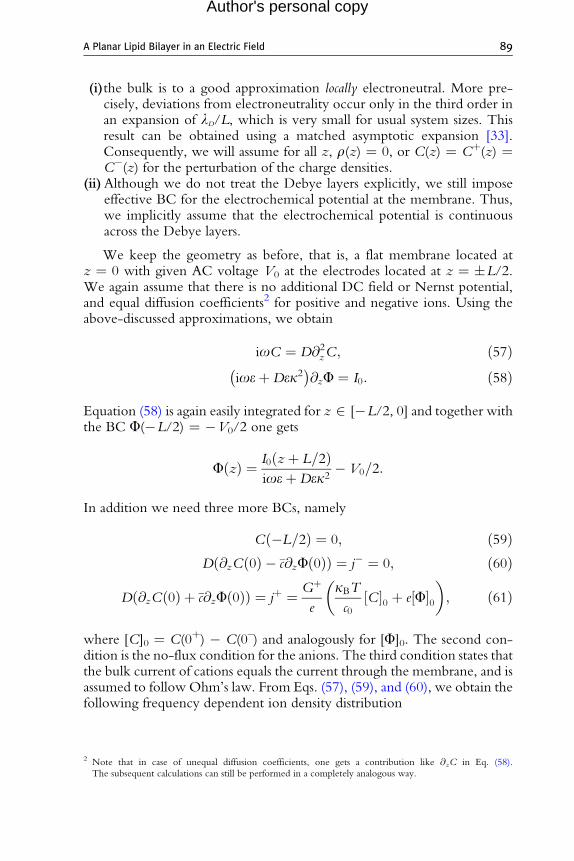
Author's personal copy
(i)the bulk is to a good approximation locally electroneutral. More pre-cisely, deviations from electroneutrality occur only in the third order inan expansion of lD/L, which is very small for usual system sizes. Thisresult can be obtained using a matched asymptotic expansion [33].Consequently, we will assume for all z, r(z) ¼ 0, or C(z) ¼ Cþ(z) ¼C�(z) for the perturbation of the charge densities.
(ii)Although we do not treat the Debye layers explicitly, we still imposeeffective BC for the electrochemical potential at the membrane. Thus,we implicitly assume that the electrochemical potential is continuousacross the Debye layers.
We keep the geometry as before, that is, a flat membrane located atz ¼ 0 with given AC voltage V0 at the electrodes located at z ¼ �L/2.We again assume that there is no additional DC field or Nernst potential,and equal diffusion coefficients2 for positive and negative ions. Using theabove-discussed approximations, we obtain
ioC ¼ D@2zC; ð57Þ
ioeþDek2� �
@zF ¼ I0: ð58Þ
Equation (58) is again easily integrated for z 2 [�L/2, 0] and together withthe BC F(�L/2) ¼ �V0/2 one gets
F zð Þ ¼ I0 zþ L=2ð ÞioeþDek2
� V0=2:
In addition we need three more BCs, namely
C �L=2ð Þ ¼ 0; ð59ÞD @zC 0ð Þ � �c@zF 0ð Þð Þ ¼ j� ¼ 0; ð60Þ
þ Gþ kBT� �
D @zC 0ð Þ þ �c@zF 0ð Þð Þ ¼ j ¼e c0
C½ �0 þ e F½ �0 ; ð61Þ
where [C]0 ¼ C(0þ) � C(0–) and analogously for [F]0. The second con-dition is the no-flux condition for the anions. The third condition states thatthe bulk current of cations equals the current through the membrane, and isassumed to follow Ohm’s law. From Eqs. (57), (59), and (60), we obtain thefollowing frequency dependent ion density distribution
2 Note that in case of unequal diffusion coefficients, one gets a contribution like @zC in Eq. (58).The subsequent calculations can still be performed in a completely analogous way.

90 F. Ziebert and D. Lacoste
Author's personal copy
C zð Þ ¼ ek2I02a ioeþDek2ð Þ cosh aL=2ð Þ sinh a zþ L=2ð Þð Þ;
where a ¼ ffiffiffiffiffiffiffiffiffiffiffiio=D
pis of Warburg-type, cf. Eq. (54). Note that here the
Warburg impedance arises from breaking the cation/anion symmetry, dueto differences in membrane conductivities rather than due to differences intheir diffusion coefficients as in the previous section. Also note thatalthough the membrane is non-conductive for the anions, this is a collectiveeffect in which both types of moving charges participate.
Finally, we use the BC for the cationic current, Eq. (61), to solve for thevoltage V0 and obtain the impedance via Z ¼ V0/(I0A) as before
Z ¼ ZB þDk2= GþAð ÞDk2 þ io
þ kBΤk2= ec0Að ÞioþDk2
tanh aL=2ð Þa
� ð62Þ
Here we already have identified the bulk circuit, it is present as in theprevious cases. The second term is the membrane contribution. It can bewritten as
ZM ¼ 1
R�1M þ ioCM
; ð63Þ
with the membrane’s resistance, RM ¼ 1/(GþA), and capacitance, CM ¼GþA/Dk2. The third term is the Warburg impedance, reading
ZW ’ 2l2DDeA=L
tanhð ffiffiffiffiffiffiffiffiffiffiffiio=D
pL=2Þffiffiffiffiffiffiffiffiffiffiffi
io=Dp
Lð64Þ
for small o.Note that it is of the same form as Eq. (56) obtained for unequaldiffusion coefficients, except for that in the latter appears an additional factorcontaining the diffusion coefficients.
We can conclude that as a result of the ionic membrane selectivity, aWarburg impedance arises. Figure 7 shows the effective circuit. A Nyquistplot is given in Fig. 8. One can identify the typical shape of a Warburgimpedance for low frequencies: namely, for decreasing frequencies, onleaving the RC-signal of the bulk � Im[Z(o)]/Re[Z(o)] acquires a slopeof 45�. Finally, due to the finite system size Im[Z(o)] vanishes for o ! 0.
As already stated above, the calculation in this Section 3.5 is over-simplified. By assuming that the electrochemical potential is continuousacross the Debye layers, there is no explicit contribution from the chargingof the Debye layers to the impedance. Hence lm, which is important for thecharging, does not enter—indeed we did not even use the Robin-typecondition. As the membrane is conductive, at least for the cations, charging

RB RM
CMCB
ZW
Figure 7 Effective circuit for the ideally blocking and selectively conductive mem-brane, Eq. (62): Two RC-circuits, one for the bulk and one for the membrane are inseries with a Warburg resistance, caused by the ion selectivity of the membrane.
Re (Z) [W]
0.0
1.0 × 10¹⁵
5.0 × 10¹⁴
3.0 × 10152.0 × 10151.0 × 1015
–Im
(Z
) [W
]
Figure 8 Nyquist plot for a selectively conducting membrane. At high frequenciesone has an RC-semi-circle, which is either dominated by the bulk or by the membrane,depending on the membrane conductance and the dimensions of the system. The low-frequency behavior is governed by the Warburg impedance. Parameters as for Fig. 2except for: L ¼ 1 mm; k ¼ 10�6 m�1 (pure water); A ¼ 1 mm2.
A Planar Lipid Bilayer in an Electric Field 91
Author's personal copy
of the Debye layers is of minor importance for the overall impedance. Witha proper treatment of the charging of the Debye layers, using a matchedasymptotic calculation, the Robin-type condition will reoccur to match thetwo solutions and will reintroduce the length scale lm into the problem.
4. Conclusion
The study and theoretical description of the effects induced by electricfields on lipid membranes in an electrolyte is a vast, challenging, and farfrom fully explored problem, which is of relevance for many applications inbiotechnology.

92 F. Ziebert and D. Lacoste
Author's personal copy
In this review, we have presented a theoretical framework to understandsome of these effects in the simple case of a planar geometry. We have seenthe importance of capacitive effects, occurring as a result of charge accumu-lation in the vicinity of the membrane, leading to renormalized elasticmoduli and to membrane instabilities. We also have analyzed the flow fieldswhich can be induced by currents due to small membrane conductivities.We discussed these effects only for time-independent (DC) electric fields,that is, in the steady-state regime.
Clearly, time-dependent electric fields lead to capacitive charging of themembrane and to time-dependent membrane dynamics. The capacitivecharging can be described in two ways: the first approach is based on theleaky dielectric model developed by Taylor [52]. This approach is explainedand illustrated in the contribution of P. Vlahovska [53]. One advantage ofsuch an approach is that it captures the main physical effects associated withcapacitive charging without the complexity of models which deal explicitlywith the ion concentration fields. For this reason, it is useful to describe forinstance the complex shape changes occurring in closed lipid vesicles [8].
The second approach, which we used in this work, is based on theelectrokinetic PNP equations. This more refined level of descriptionincludes ion concentration fields, and therefore it is useful to describespecific effects associated for instance with the ion transport in ion channelsor for effects occurring in low salt conditions. It is also needed to describemore precisely the capacitive charging, which as we have shown hereincludes several contributions coming from the bulk, the membrane imped-ance and the Debye layers themselves. In this review, we have tried toillustrate the strength of this approach for quantifying the impedance of amembrane-electrolyte system. In particular, we have shown how effectivecircuits used to interpret experimental data can be directly derived by thismethod. The membrane selectivity with respect to ion species is crucial tounderstand the conduction properties of membranes with embedded ionchannels. We hope that our work will motivate further experimental andtheoretical investigations in this field.
ACKNOWLEDGMENTS
We would like to thank particularly Martin Z. Bazant and Petia Vlahovska for many helpfuldiscussions and access to unpublished work. We would also like to thank J. Prost, J. F.Joanny, P. Bassereau, L. Dinis, G. Toombes and S. Aimon for many inspiring discussions,and the ANR Artif-Neuron for funding. F. Z. thanks the DFG for partial funding via IRTG1642 Soft Matter Science.

A Planar Lipid Bilayer in an Electric Field 93
Author's personal copy
Appendix. Robin-type BC
In brief, this BC can be motivated for a flat membrane as follows: sincethe membrane is assumed to bear no fixed charges, the normal componentsof the electric displacement are continuous at the two interfaces betweenthe membrane and the electrolyte,
e@zf z ¼ �d=2ð Þ ¼ em@zfm z ¼ �d=2ð Þ; ðA:1Þwhere fm is the electric potential inside the membrane. Since the electricfield Em ¼ �@zfm is constant (to leading order) inside the membrane, theintegral of the inside field can be written in the following way
Emd ¼ðd=2�d=2
Emdz ¼ � fm d=2ð Þ½ � � fm �d=2ð Þ� ¼ � f d=2ð Þ � f �d=2ð Þ½ �;
where in the last step we used the continuity of the potential at themembrane surface. Together with Eq. (A.1) this yields
lm@zf z ¼ �d=2ð Þ ¼ f d=2ð Þ � f �d=2ð Þ: ðA:2ÞIf we take the limit d ! 0 while keeping lm ¼ (e/em)d constant, oneobtains Eq. (7) in the particular case of h ¼ 0 and n ¼ z. The samederivation holds for the case of a slightly perturbed membrane surfaceh(r?), where r? is the in-plane vector.
REFERENCES
[1] U. Seifert, Configurations of fluid membranes and vesicles, Adv. Phys. 46 (1997) 13.[2] D. Andelman, in: R. Lipowsky, E. Sackmann (Eds.), Handbook of Biological Physics
vol. 1A, Elsevier, Amsterdam, 1995.[3] E. Neumann, A.E. Sowers, C.A. Jordan, Electroporation and Electro-fusion in Cell
Biology, Plenum Press, New York, 1989.[4] P.T. Vernier, Y. Sun, M. Gundersen, Nanoelectropulse-driven membrane perturba-
tion and small molecule permeabilization, BMC Cell Biol. 7 (2006) 37.[5] H. Mekid, L.M. Mir, In vivo cell electrofusion, Biochim. Biophys. Acta Gen. Subj.
1524 (2000) 118–130.[6] M. Staykova, R. Lipowsky, R. Dimova, Membrane flow patterns in multicomponent
giant vesicles induced by alternating electric fields, Soft Matt. 4 (2008) 2168.[7] R. Dimova, N. Bezlyepkina, M.D. Jordo, R.L. Knorr, K.A. Riske, M. Staykova, et al.
Vesicles in electric fields: Some novel aspects of membrane behavior, Soft Matt.5 (2009) 3201.

94 F. Ziebert and D. Lacoste
Author's personal copy
[8] P.M. Vlahovska, R.S. Graci, S. Aranda-Espinoza, R. Dimova, Electro-hydrodynamicmodel of vesicle deformation in alternating electric fields, Biophys. J. 96 (2009)4789–4803.
[9] P. Peterlin, S. Svetina, B. Zeks, The prolate-to-oblate shape transition of phospholipidvesicles in response to frequency variation of an AC electric field can be explained bythe dielectric anisotropy of a phospholipid bilayer, J. Phys.: Cond. Matt. 19 (2007)136220.
[10] A. Ajdari, Pumping liquids using asymmetric electrode arrays, Phys. Rev. E 61 (2000)R45–R48.
[11] A. Gonzalez, A. Ramos, N.G. Green, A. Castellanos, H. Morgan, Fluid flow induced bynonuniformAC electric fields in electrolytes onmicro-electrodes. ii. a linear double-layeranalysis, Phys. Rev. E 61 (2000) 4019–4028.
[12] B. Hille, Ion Channels of Excitable Membranes, Sinauer Press, Sunder-land, 2001.[13] B. Alberts, Molecular Biology of the Cell, Garland, New York, 2002.[14] J.B. Manneville, P. Bassereau, D. Levy, J. Prost, Activity of transmembrane proteins
induces magnification of shape fluctuations of lipid membranes, Phys. Rev. Lett.82 (1999) 4356.
[15] J.B. Manneville, P. Bassereau, S. Ramaswamy, J. Prost, Active membrane fluctuationsstudied by micropipet aspiration, Phys. Rev. E 64 (2001) 021908.
[16] M.D.E.A. Faris, D. Lacoste, J. Pecreaux, J.-F. Joanny, J. Prost, P. Bassereau, Membranetension lowering induced by protein activity, Phys. Rev. Lett. 102 (2009) 038102.
[17] D. Lacoste, M. Cosentino Lagomarsino, J.-F. Joanny, Fluctuations of a driven mem-brane in an electrolyte, Europhys. Lett. 77 (2007) 18006.
[18] D. Lacoste, G.I. Menon, M.Z. Bazant, J.F. Joanny, Electrostatic and electrokineticcontributions to the elastic moduli of a driven membrane, Eur. Phys. J. E 28 (2009)243–264.
[19] F. Ziebert, M.Z. Bazant, D. Lacoste, Effective zero-thickness model for a conductivemembrane driven by an electric field, Phys. Rev. E 81 (2010) 031912.
[20] F. Ziebert, D. Lacoste, A Poisson-Bolzmann approach for a lipid membrane in anelectric field, New J. Phys. 12 (2010) 095002.
[21] M. Winterhalter, W. Helfrich, Effect of surface-charge on the curvature elasticity ofmembranes, J. Phys. Chem. 92 (1988) 6865–6867.
[22] H. Lekkerkerker, Contribution of the electric double-layer to the curvature elasticityof charged amphiphilic monolayers, Physica A 159 (1989) 319–328.
[23] M. Winterhalter, W. Helfrich, Bending elasticity of electrically charged bilayers -coupled monolayers, neutral surfaces, and balancing stresses, J. Phys. Chem.96 (1992) 327–330.
[24] T. Chou, M. Jaric, E. Siggia, Electrostatics of lipid bilayer bending, Biophys. J.72 (1997) 2042–2055.
[25] T. Ambjornsson, M.A. Lomholt, P.L. Hansen, Applying a potential across a biomem-brane: Electrostatic contribution to the bending rigidity and membrane instability,Phys. Rev. E 75 (2007) 051916.
[26] J. Prost, R. Bruinsma, Shape fluctuations of active membranes, Europhys. Lett.33 (1996) 321.
[27] S. Ramaswamy, J. Toner, J. Prost, Nonequilibrium fluctuations, traveling waves, andinstabilities in active membranes, Phys. Rev. Lett. 84 (2000) 3494.
[28] R.J. Hunter, Foundations of Colloid Science, Oxford University Press, Oxford, 2001.[29] V. Kumaran, Electrohydrodynamic instability of a charged membrane, Phys. Rev. E
64 (2001) 011911.[30] M. Leonetti, E. Dubois-Violette, F. Homble, Pattern formation of stationary transcel-
lular ionic currents in fucus, Proc. Natl. Acad. Sci. USA 101 (2004) 10243.

A Planar Lipid Bilayer in an Electric Field 95
Author's personal copy
[31] E.M. Itskovich, A.A. Kornyshev, M.A. Vorotyntsev, Electric current across the metal-solid electrolyte interface. i. direct current, current-voltage characteristic, Phys. StatusSolidi A 39 (1977) 229–238.
[32] K. Chu, M. Bazant, Electrochemical thin f ilms at and above the classical limitingcurrent, SIAM J. Appl. Math. 65 (2005) 1485–1505.
[33] M.Z. Bazant, K. Thornton, A. Ajdari, Diffuse charge dynamics in electrochemicalsystems, Phys. Rev. E 70 (2004) 021506.
[34] P. Sens, H. Isambert, Undulation instability of lipid membranes under an electric field,Phys. Rev. Lett. 88 (2002) 128102.
[35] F. Brochard, J.F. Lennon, Frequency spectrum of the flicker phenomenon in erythro-cytes, J. Phys. (Paris) 36 (1975) 1035.
[36] M.Z. Bazant, T.M. Squires, Induced-charge electrokinetic phenomena: Theory andmicrofluidic applications, Phys. Rev. Lett. 92 (2004) 066101.
[37] S. Lecuyer, G. Fragneto, T. Charitat, Effect of an electric field on a floating lipidbilayer: A neutron reflectivity study, Eur. Phys. J. E 21 (2006) 153–159.
[38] J. Daillant, E. Bellet-Amalric, A. Braslau, T. Charitat, G. Fragneto, F. Graner, et al.Structure and fluctuations of a single floating lipid bilayer, Proc. Natl. Acad. Sci. USA102 (2005) 11639–11644.
[39] N. Gov, Membrane undulations driven by force fluctuations of active proteins, Phys.Rev. Lett. 93 (2004) 268104.
[40] S. Sankararaman, G.I. Menon, P.B. Sunil Kumar, Electrostatic and electrokineticcontributions to the elastic moduli of a driven membrane, Phys. Rev. E 66 (2002)031914.
[41] D. Lacoste, A. Lau, Dynamics of active membranes with internal noise, Europhys. Lett.70 (2005) 418.
[42] H.-Y. Chen, Internal states of active inclusions and the dynamics of an active mem-brane, Phys. Rev. Lett. 92 (2004) 168101.
[43] M.A. Lomholt, Mechanics of nonplanar membranes with force-dipole activity, Phys.Rev. E 73 (2006) 061913.
[44] J.O.M. Bockris, A.K.H. Reddy, Modern Electrochemistry, Kluwer Academic/Plenum Press, New York, 2000.
[45] G. Wiegand, N. Arribas-Layton, H. Hillebrandt, E. Sackmann, P. Wagner, Electricalproperties of supported lipid bilayer membranes, J. Phys. Chem. B 106 (2002)4245–4254.
[46] E.K. Schmitt, C. Weichbrodt, C. Steinem, Impedance analysis of gramicidin d in pore-suspending membranes, Soft Matt. 5 (2009) 3347–3353.
[47] I. Rubinstein, B. Zaltzman, A. Futerman, V. Gitis, V. Nikonenko, Reexamination ofelectrodiffusion time scales, Phys. Rev. E 79 (2009) 021506.
[48] J.D. Jackson, Classical Electrodynamics, Wiley, New York, 1999.[49] D. Andrieux, P. Gaspard, Stochastic approach and fluctuation theorem for ion trans-
port, J. Stat. Mech. Theor. Exp. 2009 (2009) P02057.[50] E. Warburg, Ueber das verhalten sogenannter unpolarisirbarer elektro-den gegen
wechselstrom, Ann. Phys. (Lpz.) 67 (1899) 493(Ser. 3).[51] E. Warburg, Polarization capacity of platinum, Ann. Phys. 6 (1901) 125.[52] J.R. Melcher, G.I. Taylor, Electrohydrodynamics: a review of the role of interfacial
shear stresses, Annu. Rev. Fluid Mech. 1 (1969) 111–146.[53] P. Vlahovska, Adv. Planar Lipid Bilayers Liposomes 12(2010) (1969) 111–146.