pryda timber connectors - midstate hardware
TRANSCRIPT

Pryda Timber ConnectorsHangers & Truss Boots Guide
A complete guide to the design, specification andinstallation of Pryda Hangers and Truss Boots
July 2010
ESSENTIAL NOTES – PRYDA PRODUCT GUIDES
Copyright: © Pryda Australia - A Division of ITW Australia – ABN 63 004 235 063 - 2010
INTRODUCTION The information in this Product Guide is provided for use in Australia by architects, engineers, building designers, builders and others. It is based upon the following criteria:
1. No Substitution: The products covered by or recommended in
this guide must not be substituted with other products.
2. Design Capacity Basis: See Codes & Standards following
3. Supporting Constructions: Constructions using Pryda
products must be built in accordance with the BCA or an appropriate Australian standard. Note: This includes appropriate corrosion protection- See Corrosion Protection following
4. Correct Installation: Installation of Pryda products must be
strictly in accordance with the instructions in this guide
5. Current Guide Version Used: The current version of this
guide, including any amendments or additions, must be used. Users are advised to check with Pryda for updates at least every three months by telephone, the web site: www.pryda.com.au or by email to: [email protected].
CODES & STANDARDS Product design capacities in this guide have been derived from:
(a) results of laboratory tests carried out by or for Pryda Australia
(b) engineering computations in accordance with the relevant Australian standards, ie:
* AS1720.1-1997 Timber Structures. Part 1: Design Methods
* AS/NZS1170:2002 Structural Design Principles
* AS4055 -2006 Wind Loads for Housing
Reference is also made to AS1684.1-1999 Residential Timber Framed Construction - Part 1: Design Criteria.
Design capacities tabulated in this guide apply directly for joints in houses and on secondary beams in other structures. For joints on primary beams in structures other than houses, reduce the capacity as specified in page 4 (if applicable). Design capacities are related to the Joint Group of the timber as defined in AS1720 and AS1684. If the joint group of timber members joined together varies, the lower group must be assumed for design, eg: JD5 is lower than JD4. Load Duration Factor for Wind
Wind Uplift capacities are based on the AS1720.1:1997 (Amdt No.4 Nov 2002) using k1=1.14, for use in conjunction with AS/NZS1170:2002 loading code
DEFINITIONS Special terms used in this guide are as defined in Australian standards, including:
Design Capacity: the maximum Limit State Design load (aka
“action”) which the product can safely support under the specified load condition, eg: 1.2G + 1.5Q (dead+roof live). See page 4 for details (if applicable)
Joint Group: classification of a timber according to its fastener-
holding capacity. See page 4 for details (if applicable)
CORROSION PROTECTION
Most Pryda products are manufactured using Z275 light-gauge steel, having zinc coating of 275 gsm (total weight). This protection is adequate only for INTERNAL applications in most corrosion environments, except areas that are classified as heavy industrial or those subject to high humidity (eg: enclosed swimming pools) etc. Under these circumstances, seek advice from experts as special protection will be required. Note: INTERNAL areas are those within the building envelope that are kept permanently dry.
AS1684.2-2010 and AS1684.3-2010- Australian Standards for Residential Timber Frame Construction stipulates a minimum Z275 steel for all sheet metal products used in an internal environment.
In areas outside the building envelope that are exposed to repeated wetting (EXTERNAL areas), Pryda’s stainless steel products or equivalent should be considered. Some alternatives include hot dip galvanised or powder coated steel, which are not supplied by Pryda. For more detailed information, read Pryda’s Technical Update on Corrosion Resistance of Pryda Products or contact a Pryda office.
LIMITED WARRANTY Pryda Australia warrants:
* Products in this guide are free from defects in the material or manufacturing
* Design capacities are in accordance with test results or current, relevant Australian standards and the Building Code of Australia.
* Pryda products are structurally adequate provided they are designed, installed and used completely in accordance with this guide.
This warranty applies only to:
* products in this guide
* products used in the specified applications and not damaged after manufacture and supply
* joints free from wood splitting, decay or other timber defects within the joint or within 150 mm of the joint.
INSTRUCTIONS FOR INSTALLATION These notes are provided to ensure proper installation.
1. All fasteners used must be manufactured by reputable companies and be of structural quality.
2. Connectors must not be installed on timber which is split before or during installation. If the timber is likely to split as fasteners are driven, fastener holes must be pre-drilled.
3. Do not overload the joints- during construction or in service.
4. Bolt hole diameter must be 0.8 mm to 1.5 mm larger than the bolt diameter and the specified washers must be installed.
5. Use proper safety equipment and due care in installing these connectors
6. Any gaps in joints between the timber members must not exceed 3 mm
7. Do not over-tighten screws.

Pryda Hangers & Truss Boots Guide
INDEX
GENERAL NOTES
Useful Notes and Definitions for effective reading of this guide 4
BEAM HANGERS Heavy brackets for large size beams 5
I-JOIST HANGERS Top mount and face mount hangers for timber I-joists
7
LVSIA – angle brackets Brackets used as either angle cleat or angle seat 12
FRAMING BRACKETS Brackets for beam to beam connections
13
JOIST HANGERS (HEAVY DUTY) Brackets for heavy beam to beam or beam connections Joist Hangers- Split
16
17
TRUSS BOOTS – MULTI FIX For Truss to Truss Connections with option for fixing with bolts and screws 18
TRUSS BOOTS – HEAVY DUTY Bolted Steel Brackets for Heavy Roof Truss to Truss Connections
23
BOLTS KITS FOR TRUSS BOOTS Kits of bolts, nuts and washers for fixing truss boots 24
HIP SUPPORT BRACKETS Brackets to connect hip trusses to girders 28
Product Information Updates
Information contained in this product guide is subject to change. The latest updates are available from www.pryda.com.au.

PRYDA TIMBER CONNECTORS Hangers & Truss Boots Guide
4 PRYDA HANGERS & TRUSS BOOTS GUIDE – JULY 2010
GENERAL NOTES Timber Joint Groups Joint groups for some common timber are tabulated below. A more comprehensive table is given in AS1720.1 Timber Structures Part 1: Design Methods.
Timbers Strength Group Joint Group
Dry Green Dry Green
Oregon (Douglas fir) – America SD5 S5 JD4 J4
Oregon from elsewhere SD6 S6 JD5 J5
Radiata pine, heart-excluded SD6 NA JD4 NA
Radiata pine, heart-in SD6 NA JD5 NA
Slash pine SD5 S5 JD3 J3
Ash type hardwoods from Vic, NSW highlands & Tas
SD4 S4 JD3 J3
Non-Ash type hardwoods from Qld & NSW
SD3 S3 JD2 J2
Material Thickness All material thicknesses referred to in this guide are the total coated thickness. This includes the zinc coating thickness, which is typically around 0.04mm for Z275 steel. Design Load Cases Following is a description of the combined load cases adopted in this design guide. These load cases are in compliance with AS/NZS1170.0:2002 – Structural design actions Part 0:General principles
Design Loads & Capacities The tabulated capacities are for Category 1 joints. For all other joints, reduce design capacities by using the following factors:
Category 2 Joints: 0.94
Category 3 Joints: 0.88
Note: Category 1 joints are defined in Table 2.2 AS1720.1:2010 as structural joints for houses for which failure would be unlikely to affect an area of 25 sqm OR joints for secondary elements in structures other than houses.
Fastener Usage Summary Following is a summary of the common nails, screws and bolts used in hangers and truss boot fixing. Read the relevant page in this guide for a detailed specification for the respective hanger and truss oot.
** Only used for TBHD75/T or TBHD75 out of the HD truss boots. Note on Pryda Product Codes:
(a) No.12 Type 17 screws in the above table refer to either WTF12-35 or WSF12-35 or WTF12-65.
(b) M12 bolts refer to OBS12/65 or OBS12/100 set screws or OBM12/150 or OBM12/180 hex-head bolts used in conjunction with OW12/56S washers.
(c) M16 bolts refer to OBS16/110 set screws or OBM16/150 or OBM16/180 hex-head bolts used in conjunction with OW16/63S washers.
Machine Driven Nail Use Where appropriate, 32x2.3 mm Duo-Fast C SHEG (ie: screw hardened electro galvanized) machine driven nails (code D40810) or equivalent may be used instead of the specified 35x3.15 mm Pryda Timber Connector Nails to fix Pryda connectors provided that:
20% more nails are used (eg: 5 instead of 4, 4 instead of 3, 3 instead of 2) or alternatively, design capacities are to be reduced by 20% where the same number of nails are used
machine driven nails are driven at nail spacings and edge distances similar to the hole pattern, ensuring that these nails are not driven into the holes or located not closer than 5mm from the edge of a hole.
Fixing into steel supporting structure Pryda products can be fixed into steel using Teks screws or similar. Design Capacities can be obtained at request from a Pryda Design Office. Information on fixing Pryda hangers or truss boots into LSBTM is available in the publication LiteSteel® Beam Design Guide: Timber Connections available on our website.
Load Case Description
1.35G Permanent Action (or Dead Load) only
1.2G+1.5Qr Permanent and Roof Imposed Actions (or Dead & Roof Live)
1.2G+1.5Qf Permanent and Floor Imposed Actions (or Dead & Floor Live)
1.2G+Wd Permanent and Wind down Actions (or Dead & Wind down)
Wind Uplift (0.9G – Wup)
Permanent and Wind Up Actions (or Dead & Wind up)
Pry
da
Tim
ber
C
on
nec
tor
Nai
ls
(35
x 3.
15 d
ia)
Pry
da
Tim
ber
C
on
nec
tor
Nai
ls
(40
x 3.
75 d
ia)
No
.12
Typ
e 1
7 sc
rew
s
M12
Bo
lts
wit
h
was
her
s
M16
Bo
lts
wit
h
was
her
s
I joist Hangers Y
Framing Brackets Y Y
HD Joist Hangers Y
LVSIA and HSB Y
Truss Boots Y Y Y
HD Truss Boots
Y** Y

PRYDA TIMBER CONNECTORS Hangers & Truss Boots Guide
5 PRYDA HANGERS & TRUSS BOOTS GUIDE – JULY 2010
BEAM HANGERSHeavy Brackets for Large Size Beams & I-joists
Beam Hanger for Beams Beam Hanger for I-
Joists Description Pryda Beam Hangers are heavy duty welded hangers for connection of large size beams or I-joists, ranging in thickness from 45 mm to 180 mm, to timber beams or masonry walls.
Features Pryda Beam Hangers are:
easy to install with a small number of coach screws and/or nails onto timber or with masonry anchors onto masonry or concrete
an economical means of forming these connections
ideal for supporting heavily loaded beams on fire rated brick walls, eliminating the need for a girder truss or false wall to support the beams
additional top flange holes on two sizes to allow for easy casting into mortar joints
180mm wide hangers support double I-joists
Supply Beam Hangers are supplied individually.
Dimensions Dimensions of Pryda Beam Hangers are shown below.
Hanger Dimensions (mm)
Code D W BL1 BL2
BB180 186 77 75 65
BB300 306 77 75 65
BBT180240 240 180 75 65
BBT180300 300 180 75 65
BBT180360 360 180 75 65
Specifications Pryda Beam Hangers are manufactured out of G250, 3mm thick steel and are hot dipped galvanized to a minimum 300 gsm.
Beam Hangers for Beams (BB Series)
180mm wide Beam Hangers for double I-joists (BBT Series)
75
H
200
Coach screwholes are offset
to avoid clashof screws
in beamW
Holes for 3.75 mm nails
Holes for10 mm diam.coach screws
PLAN VIEW
40
Holes on BB45240
& BB75240 for fixing to
masonry
BL1 BL2Weldedjoint
Holes for3.75 mmnails- twoeach legHole for10 mm diam.coach screw,one per leg
D
W65
75
75
Welded Joint
Holes Each Side for Nail Fixing to Bottom
Chord of i-joist
Holes for Fixing to Support
PRYDA TIMBER CONNECTORS Hangers & Truss Boots Guide
6 PRYDA HANGERS & TRUSS BOOTS GUIDE – JULY 2010
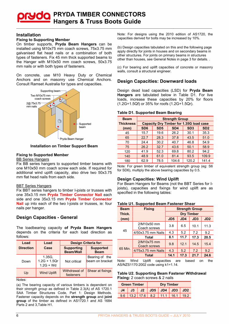
Installation Fixing to Supporting Member On timber supports, Pryda Beam Hangers can be installed using M10x75 mm coach screws, 75x3.75 mm galvanised flat head nails or a combination of both types of fasteners. Fix 45 mm thick supported beams to the Hanger with M10x50 mm coach screws, 50x3.75 mm nails or with both types of fasteners. On concrete, use M10 Heavy Duty or Chemical Anchors and on masonry use Chemical Anchors. Consult Ramset Australia for types and capacities.
Installation on Timber Support Beam Fixing to Supported Member BB Series Hangers Fix BB series hangers to supported timber beams with one M10x50 mm coach screw each side. If required for additional wind uplift capacity, also drive two 50x3.75 mm flat head nails from each side. BBT Series Hangers Fix BBT series hangers to timber I-joists or trusses with one 35x3.15 mm Pryda Timber Connector Nail each side and one 35x3.15 mm Pryda Timber Connector Nail up into each of the two I-joists or trusses, ie: four nails per hanger. Design Capacities - General
The loadbearing capacity of Pryda Beam Hangers depends on the criteria for each load direction as follows:
Load Load Design Criteria for:
Direction Case Supporting Beam/Wall
Supported Beam
Down 1.35G,
1.2G + 1.5Qr 1.2G + Wd
Not critical Bearing of the
beam on bracket
Up Wind Uplift Withdrawal of
fasteners Shear at fixings
Notes:
(a) The bearing capacity of various timbers is dependent on their strength group as defined in Table 2.3(A) of AS 1720.1 SAA Timber Structures Code, Part 1: Design Methods. Fastener capacity depends on the strength group and joint group of the timber as defined in AS1720.1 and AS 1684 Parts 2 and 3,Table H1.
Note: For designs using the 2010 edition of AS1720, the capacities derived for bolts may be increased by 10%.
(b) Design capacities tabulated on this and the following page apply directly for joints in houses and on secondary beams in other structures. For joints on primary beams in structures other than houses, see General Notes in page 3 for details. . (c) For bearing and uplift capacities of concrete or masonry walls, consult a structural engineer.
Design Capacities: Downward loads Design dead load capacities (LSD) for Pryda Beam Hangers are tabulated below in Table D1. For live loads, increase these capacities by 20% for floors (1.2G+1.5Qf) or 35% for roofs (1.2G+1.5Qr). Table D1. Supported Beam Bearing
Beam Strength Group Thickness Capacity Dry Timber for 1.35G load case
(mm) SD6 SD5 SD4 SD3 SD2 45 15.7 19.6 26.2 30.1 35.3
65 22.7 28.3 37.8 43.5 51.0 70 24.4 30.2 40.7 46.8 54.9 75 26.2 32.7 43.6 50.1 58.9
120 41.9 52.3 69.8 80.2 94.2
140 48.9 61.0 81.4 93.5 109.9
180 62.9 78.5 104.6 120.2 141.4
Note: For green timber of equivalent strength group (eg: S6 for SD6), multiply the above bearing capacities by 0.5. Design Capacities: Wind Uplift For Beam Hangers for Beams (not the BBT Series for I-joists), capacities and fixings for wind uplift are as specified in the following tables:
Table U1. Supported Beam Fastener Shear Beam Fixing Strength Group
Thick. Dry Timber
(mm) JD5 JD4 JD3 JD2
45
2/M10x50 mm Coach screws
3.8 6.5 10.1 11.3
4/50x3.75 mm Nails 4.3 5.2 7.2 9.2 Total 8.1 11.7 17.3 20.5
65 Min.
2/M10x75 mm Coach screws
9.8 12.1 14.5 15.4
4/75x3.75 mm Nails 4.3 5.2 7.2 9.2 Total 14.1 17.3 21.7 24.6
Note: Wind Uplift capacities are based on the AS/NZS1170:2002 code using k1=1.14. Table U2. Supporting Beam Fastener Withdrawal Fixing: 2 coach screws & 2 nails
Green Timber Dry Timber
J4 J3 J2 JD5 JD4 JD3 JD2
9.6 13.2 17.6 8.2 11.1 16.1 19.2
Supported beam
Supporting beam
Two M10x75 mmcoach screws
2@ 75x3.75mm nails
Pryda Beam Hanger

PRYDA TIMBER CONNECTORS Hangers & Truss Boots Guide
7 PRYDA HANGERS & TRUSS BOOTS GUIDE – JULY 2010
I-JOIST HANGERSFace mount and top mount hangers for timber I-joists
Features Pryda I-Joist Hangers have features as follows:
Ideally suited to support of modern timber I-Joists.
Use of full depth hangers provides torsional restraint to the I-joist.
There is provision for a screw through the hanger into the bottom of the bottom flange to minimize squeaking. Some hangers (LT range) has holes on the side for fixing into bottom flange to further reduce the effect of squeaking.
Description LT and LF types hangers are specifically designed for use with proprietary I-Joists such as Carter Holt Harvey hyJOIST, Tillings SmartFrame I-joist, Hyne I-Beam and Wesbeam e-joist. Refer guide in page 112. LT type are for top fixing and LF for face fixing. LFVS are variable slope and skew. LFSL and LFSR are 45o degree skewed, left and right respectively. LVSIA type is a variable skew angle. Specification Dimensions are tabulated on the next page. All hangers are manufactured from G300 Z275 galvanised steel in 1.2 mm thickness, except for:
LFSL/SR - 2.0 mm
LF220/105, LF300/105, LT240/105 - 1.6 mm
LT300/105, LT356/121 - 2.6 mm
LVSIA (G250, hot dip galv) - 5 mm Packaging All products are packaged in quantities of 25 per carton except some of the largest hangers which are sold 15 per carton and LVSIA at 10 per carton. See the Price List for details. Details of the available range of Pryda I-Joist Hangers are tabulated in the following. ‘Double’ I-Joist Hangers are for support of two I-Joists, side by side or a single 90 or 120 mm wide I-Joist.
Bracket Types
Pryda I-Joist Hanger types are illustrated below:
LF Type Face Mount
LT Type #1 Top Mount
LFVS Type Variable Slope & Skew
LFSL/SR Type 45 deg Skewed Hanger
LVSIA Type Angle Bracket
Dimensions H, B and W are tabulated in the Dimension tables following. LT Type 2 applies for Hangers: LT240/52, LT300/52, LT356/60, LT302/65, LT356/65, LT356/70, LT240/70, LT302/70, LT240/90, LT245/90, LT300/90, LT356/90. LT Type 1 applies to all other LT hangers.
W B
H
D
W B
H
Holes available with some LT brackets

PRYDA TIMBER CONNECTORS Hangers & Truss Boots Guide
8 PRYDA HANGERS & TRUSS BOOTS GUIDE – JULY 2010
Dimensions Dimensions as shown on previous page (Bracket Types) are as follows:
Face Mount
Product Code
H W B Face Nail
mm mm mm Holes
LF235/40 235 40 50 10
LF297/40 297 40 50 12
LF190/50 190 50 50 8
LF235/50 235 50 50 10
LF297/50 297 50 50 12
LF340/60 340 60 50 14
LF235/65 235 65 50 10
LF290/65 290 65 50 12
LF340/65 340 65 50 14
LF190/90 190 90 50 8
LF235/90 235 90 50 10
LF290/90 290 90 50 12
LF350/90 350 90 50 14
LF220/105 220 105 50 8
LF235/120 235 120 50 10
LF290/130 290 130 50 12
LF235/180 235 180 50 10
Top Mount
Product H W B D Face Top Code Nail Nail mm mm mm mm Holes Holes
LT240/40 240 40 50 40 4 6
LT300/40 300 40 50 40 4 6
LT300/47 300 47 50 40 4 6
LT200/50 200 50 50 40 4 6
LT240/50 241 50 50 42.5 4 6
LT240/52 240 52 50 40 4 6
LT300/52 302 52 50 40 4 6
LT360/60 246 60 50 40 4 6
LT240/65 240 65 50 40 4 6
LT302/65 302 65 50 40 4 6
LT360/65 356 65 50 40 4 6
LT200/90 200 90 50 40 4 6
LT240/90 240 90 50 60 4 6
LT245/90 245 90 50 40 4 6
LT300/90 300 90 50 40 4 6
LT360/90 360 90 50 40 4 6
LT400/90 302 105 50 40 4 6
LT240/105 240 105 50 40 4 6
LT300/105 300 105 50 40 4 6
LT356/121 356 121 76 40 4 6
Variable Slope & Skew, Face Mount
Product Code
H W B Face
Nail
mm mm mm Holes
LF215/90SL 215 90 64 16
LF215/90SR 215 90 64 16
LF275/60SL 275 60 64 16
LF275/60SR 275 60 64 16
LF190/47VS 190 47 70 10
LF224/59VS 224 59 70 14
LF224/65VS 224 65 70 14
LF224/90VS 224 90 70 14
Installation - Fixing 1. Use only 40x3.75 mm galvanised Pryda Timber Connector
Nails, Pryda product code OSNIB/1 or OSNIB/5.
2. For screwing the joist to the hanger seat, use No. 6 x 30 mm bugle-head or wafer-head wood screws.
3. All nail holes are to be filled with the specified nails in order to achieve hanger capacity.
Installation To achieve the specified design loads, Pryda I-Joist Hangers must be correctly installed as specified in the following topics:
Installation - General Refer to l-joist manufacturers’ instruction manuals for span table selection and other details for on-site installation of their systems. Installation – Face Mount Hangers
Max. Gap 3mm Resist Lateral Movement
10mm Min
Top Flange of i-jRestrained
Note: Use the recommended screw to seat the I-Joist into the hanger properly to help reduce squeaks.

PRYDA TIMBER CONNECTORS Hangers & Truss Boots Guide
9 PRYDA HANGERS & TRUSS BOOTS GUIDE – JULY 2010
Installation – Top Mount Hangers
Note: Use the recommended screw to seat the I-Joist into the hanger properly to help minimize squeaks. Alternatively, if nails are used from sides (holes available with some LT brackets), ensure special nails are adopted to avoid squeaks from nails coming in contact with the hanger’s seat.
Installation – LVSIA
Notch bottom chord of I-joists55x5 mm for flush finish
Fix I-joist to LVSIA Anglewith 1@ No. 10 x 30 mmType 17, Countersunk screw
I-joist/I-beamBeam or Waling Plate 40 mm min.
thickness
Notch end of I-joist80x10 mm approx.
for LVSIA Angle
Fix LVSIA Angle tosupporting beam or
waling plate with4@ No. 12 Type 17
hex. head screwssee table - page 11
for screw length
Pryda LVSIA Angle75x50x5 UA
x 150 mm long
Fix top chord to supportwith 2/75x3.05 mm nails
Installation – Common Problems Poor or incorrect installation can lead to serious problems. Common problems are illustrated opposite:
Minimum 3 mm, max. 6 mm space
to eliminate contactbetween hanger and steel which
may cause squeaks
3 mm maximumclearance
Installation- Variable Skew Angles LVSIA variable skew angles are installed as shown in the following diagram, ie: 1. Notch the I-joist at ends to provide for fitting the LVSIA. 2. Locate the angle with the 75 mm leg vertical and its mid-
length at the middle of the required end location of the I-joist. Fix the angle to the supporting beam, waling plate or ledger with 4 or 6 No. 12 Type 17 screws. Note: The capacities in page 10 are given for 35mm screw lengths, but 40mm screw lengths may be used to achieve increased capacities.
3. Locate the I-joist on the angle and fix it up through the bottom of angle with 1@ No. 10 x 30 mm countersunk or bugle head Type 17 screw.
4. Nail the I-joist top chord to the support with 2/75x3.05 mm nails.
If the top plate is too narrow it may cause:
1. Hanger Deformation. 2. Nail pull-out or
shear. 3. Supporting beam
deformation
Spreading hanger legs will push the joist up which may cause un-even floors, squeaky floors and joist rotation.
Joist is not seated properly in to the hanger. This may cause nail pull-out.

PRYDA TIMBER CONNECTORS Hangers & Truss Boots Guide
10 PRYDA HANGERS & TRUSS BOOTS GUIDE – JULY 2010
Design Capacities Tabulated below are design capacities for Pryda I-joist Hangers fixed with the number of nails tabulated. “Face nails” are driven into the face of the supporting beam, “Top nails” into the top of the supporting beams and “Joist nails” into the carried member. General Notes 1. For joints on primary beams in structures other than
houses, see General Notes in page 3 for information.
2. Fixing into supporting member : Use only Pryda
40x3.75mm or 35x3.75 mm galvanised Pryda TimberConnector Nails, or equivalent for all LF and LTbrackets. No.12 Type 17 screws to be used for fixingLVSIA bracket.
3. “Dead” is dead load plus any portion of live loadconsidered to be permanent.
Face Mounted Hangers With a minimum of eight face nails, these hangers can carry the design residential floor loads of (1.5 kPa live) for joists up to 5.9 m span at 600 mm spacing or 7.9 m span at 450 mm spacing, provided that the timber in supporting beams has a joint group of JD4 or better.
Hanger Codes Face
Nails
1.2G + 1.5Qf (Dead & Floor Live )
Design Capacity, ФNj (kN), for
Supporting Beam with Joint Group:
J4 J3 JD5 JD4 JD3
All LF190/.. and
LF220/.. 8 4.4 6.2 5.2 6.2 8.7
All LF 235/.. 10 5.5 7.8 6.4 7.8 10.9
All LF290/.. and
LF297/.. 12 6.6 9.3 7.7 9.3 13.1
All LF340/.. and
LF350/.. 14 7.7 10.9 9.0 10.9 14.2
Note: Where these hangers are fixed to a 35 mm thick supporting member, use the 40x3.75 mm nails and multiply design capacities by 0.88. Top Mounted Hangers The design capacities of top mounted brackets is greater than that required to support the applied residential floor loads (1.5 kPa live) for the I-joist products listed in this file.
Hanger
Code
Top Nails
(incl. both
top mount
tab)
1.2G + 1.5Qf (Dead & Floor Live )
Design Capacity, ФNj (kN), for
Supporting Beam with Joint Group:
JD5 JD4 JD3
All LT series 6 4.8 5.7 6.1
Note: 4 nail (2 nails on each tab) fixing may be used at reduced capacities of 4.0 (JD5), 4.7 (JD4), 5.1 (JD3).
Variable Slope & Skew Hangers Typically used to support I-joists used as roof rafters.
Hanger Code Face Nails
Joist Nails
Design Capacity, ФNj (kN), for Supporting Beam with JD5 or Higher Joint Group for Load
Case:
1.35G 1.2G+1.5Qr
Wind Uplift
LF190/47VS, LF224/59VS 10 7 2.8 4.6 3.2
LF224/65VS, LF224/90VS 14 12 4.0 6.4 4.5
Note: Where these hangers are fixed to a 35 mm thick supporting member, use the 40x3.75 mm nails and multiply design capacities by 0.88. Skewed Hangers Typically used to support I-joists used in floors at 45o to the supporting beam.
Hanger Code Face Nails
Joist Nails
Design Capacity, ФNj (kN), for Supporting Beam with JD5 or
Higher Joint Group for Load Case:
1.2G+1.5Qf (Dead & Floor Live)
LF215/90SL/R
LF275/60SL/R 16 10 5.4
Note: Where these hangers are fixed to a 35 mm thick supporting member, use the 40x3.75 mm nails and multiply design capacities by 0.88. Variable Skew Angles Used to support I-joists at an angle other than 90o to the support, LVSIA design capacities are:
Fixing in to
supporting
member using
No.12 Type 17
screws
Screw
Length 1.2G+1.5Qf (Dead&Floor live) Design Capacity, ФNj (kN), for
Supporting Beam with Joint Group:
(mm) J4 J3 JD5 JD4 JD3
4 screws 35 3.9 5.5 3.9 5.5 7.8
6 screws 35 5.8 8.2 5.8 8.2 11.5
Notes:
For joints on primary beams in structures other than houses, see General Notes in page 4 for information.
Capacities of LVSIA in other applications are given in page 13
Fixing into joist - An additional No.10x30 Type 17 counter-sunk screw is required on horizontal leg,
The capacities may be increased by 15% if 40mm screw lengths are used in to 45mm or thicker supporting beam.
PRYDA TIMBER CONNECTORS Hangers & Truss Boots Guide
11 PRYDA HANGERS & TRUSS BOOTS GUIDE – JULY 2010
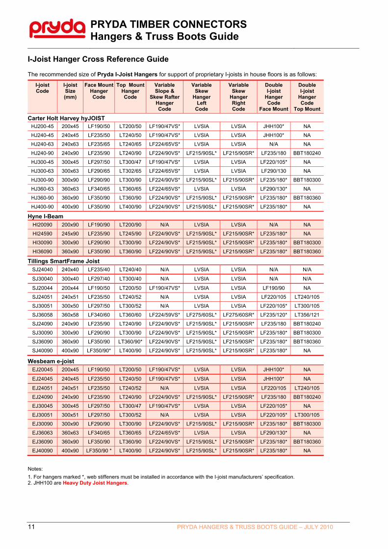
I-Joist Hanger Cross Reference Guide The recommended size of Pryda I-Joist Hangers for support of proprietary I-joists in house floors is as follows:
I-joist Code
I-joist Size (mm)
Face Mount Hanger Code
Top Mount Hanger Code
Variable Slope &
Skew Rafter Hanger Code
Variable Skew
Hanger Left
Code
Variable Skew
Hanger Right Code
Double I-joist
Hanger Code
Face Mount
Double I-joist
Hanger Code
Top Mount
Carter Holt Harvey hyJOIST HJ200-45 200x45 LF190/50 LT200/50 LF190/47VS* LVSIA LVSIA JHH100* NA
HJ240-45 240x45 LF235/50 LT240/50 LF190/47VS* LVSIA LVSIA JHH100* NA HJ240-63 240x63 LF235/65 LT240/65 LF224/65VS* LVSIA LVSIA N/A NA HJ240-90 240x90 LF235/90 LT240/90 LF224/90VS* LF215/90SL* LF215/90SR* LF235/180 BBT180240
HJ300-45 300x45 LF297/50 LT300/47 LF190/47VS* LVSIA LVSIA LF220/105* NA HJ300-63 300x63 LF290/65 LT302/65 LF224/65VS* LVSIA LVSIA LF290/130 NA HJ300-90 300x90 LF290/90 LT300/90 LF224/90VS* LF215/90SL* LF215/90SR* LF235/180* BBT180300
HJ360-63 360x63 LF340/65 LT360/65 LF224/65VS* LVSIA LVSIA LF290/130* NA
HJ360-90 360x90 LF350/90 LT360/90 LF224/90VS* LF215/90SL* LF215/90SR* LF235/180* BBT180360
HJ400-90 400x90 LF350/90 LT400/90 LF224/90VS* LF215/90SL* LF215/90SR* LF235/180* NA
Hyne I-Beam HI20090 200x90 LF190/90 LT200/90 N/A LVSIA LVSIA N/A NA
HI24590 245x90 LF235/90 LT245/90 LF224/90VS* LF215/90SL* LF215/90SR* LF235/180* NA
HI30090 300x90 LF290/90 LT300/90 LF224/90VS* LF215/90SL* LF215/90SR* LF235/180* BBT180300
HI36090 360x90 LF350/90 LT360/90 LF224/90VS* LF215/90SL* LF215/90SR* LF235/180* BBT180360
Tillings SmartFrame Joist SJ24040 240x40 LF235/40 LT240/40 N/A LVSIA LVSIA N/A N/A
SJ30040 300x40 LF297/40 LT300/40 N/A LVSIA LVSIA N/A N/A
SJ20044 200x44 LF190/50 LT200/50 LF190/47VS* LVSIA LVSIA LF190/90 NA
SJ24051 240x51 LF235/50 LT240/52 N/A LVSIA LVSIA LF220/105 LT240/105
SJ30051 300x50 LF297/50 LT300/52 N/A LVSIA LVSIA LF220/105* LT300/105
SJ36058 360x58 LF340/60 LT360/60 LF224/59VS* LF275/60SL* LF275/60SR* LF235/120* LT356/121
SJ24090 240x90 LF235/90 LT240/90 LF224/90VS* LF215/90SL* LF215/90SR* LF235/180 BBT180240
SJ30090 300x90 LF290/90 LT300/90 LF224/90VS* LF215/90SL* LF215/90SR* LF235/180* BBT180300
SJ36090 360x90 LF350/90 LT360/90* LF224/90VS* LF215/90SL* LF215/90SR* LF235/180* BBT180360
SJ40090 400x90 LF350/90* LT400/90 LF224/90VS* LF215/90SL* LF215/90SR* LF235/180* NA
Wesbeam e-joist EJ20045 200x45 LF190/50 LT200/50 LF190/47VS* LVSIA LVSIA JHH100* NA
EJ24045 240x45 LF235/50 LT240/50 LF190/47VS* LVSIA LVSIA JHH100* NA
EJ24051 240x51 LF235/50 LT240/52 N/A LVSIA LVSIA LF220/105 LT240/105
EJ24090 240x90 LF235/90 LT240/90 LF224/90VS* LF215/90SL* LF215/90SR* LF235/180 BBT180240
EJ30045 300x45 LF297/50 LT300/47 LF190/47VS* LVSIA LVSIA LF220/105* NA EJ30051 300x51 LF297/50 LT300/52 N/A LVSIA LVSIA LF220/105* LT300/105
EJ30090 300x90 LF290/90 LT300/90 LF224/90VS* LF215/90SL* LF215/90SR* LF235/180* BBT180300
EJ36063 360x63 LF340/65 LT360/65 LF224/65VS* LVSIA LVSIA LF290/130* NA
EJ36090 360x90 LF350/90 LT360/90 LF224/90VS* LF215/90SL* LF215/90SR* LF235/180* BBT180360
EJ40090 400x90 LF350/90 * LT400/90 LF224/90VS* LF215/90SL* LF215/90SR* LF235/180* NA
Notes:
1. For hangers marked *, web stiffeners must be installed in accordance with the I-joist manufacturers’ specification. 2. JHH100 are Heavy Duty Joist Hangers.

PRYDA TIMBER CONNECTORS Hangers & Truss Boots Guide
12 PRYDA HANGERS & TRUSS BOOTS GUIDE – JULY 2010
LVSIA ANGLE BRACKET Applications LVSIA is a versatile bracket that can be used in a ‘horizontal’ direction as an angle SEAT to support beams or trusses coming in at any direction. This angle bracket can also be used in a ‘vertical’ direction as an angle CLEAT for beam to beam connections especially in situations where normal joist hangers cannot be used. Specifications LVSIA bracket is a 150mm long x 5.0mm thick un-equal angle of size 75 x 50 x 5.0 using G300 galvanized steel. Design Capacities (A) ‘Vertical’ Application as an angle CLEAT– Bracket fixed only on one face Fixings – 6/No.12 x 40 Type 17 hex-head screws on each leg.
Installation: 50mm leg fixed to supporting beam
JOINT GROUP
Single LVSIA as an angle cleat for given Load Cases
1.35G 1.2G+1.5Qf 1.2G+1.5Qr Wind Uplift
JD4 5.3 6.4 7.1 9.6
JD3 (1) 7.4 8.9 10.0 14.8
Notes: (1) Provide 2/No.14 x 90 screws from the back of
supporting beam in to end-grain of supported beam to resist twisting of supporting beam. Use longer screw lengths if required to ensure a minimum 35mm penetration.
(2) When the supported member used is prone to splitting (like hardwoods-JD3), additional precautions should be taken. These can be in the form of prebored holes or provision of anti-split nailplates at ends of the supported beam.
(3) Screws with longer lengths are required when LVSIA brackets are fixed into multiple laminated beams. For double laminates, use 65 long screws per flange.
(B) ‘Horizontal’ Application as an angle SEAT Fixings – 6/No.12 x 35 Type 17 hex-head screws on vertical leg and 1/No.10x30 Type 17 counter-sunk screw on horizontal leg.
. Notes:
(1) The above table values may be increased by 15% if 40mm screw lengths are used
JOINT GROUP
LOAD CAPACITIES(kN) for LVSIA as an angle seat for given Load Cases
1.35G 1.2G+1.5Qf 1.2G+1.5Qr Wind Uplift
JD5 4.8 5.8 6.5 1.0
JD4 6.7 8.2 9.1 1.4
JD3 9.5 11.5 12.9 1.8
Fixings to Supporting Beam: 6 screws in to 50mm leg Fixings to Supported Beam:
6 screws in to 70mm leg

PRYDA TIMBER CONNECTORS Hangers & Truss Boots Guide
13 PRYDA HANGERS & TRUSS BOOTS GUIDE – JULY 2010
FRAMING BRACKETS AND HEAVY DUTY JOIST HANGERS Brackets for Beam to Beam or Beam to Brickwork/Concrete Connections
Framing Bracket for beam to beam
Connections
Heavy Duty Joist Hanger for Large Sizes, Heavy Loads
Split Joist Hanger for
Heavy Loads
General Description Pryda Framing Brackets, Split Joist Hangers and Heavy Duty Joist Hangers have been preferred and used in Australia and overseas for more than 20 years. They are strong, easy to install, cost effective, well designed connectors for many timber beam to beam and beam to concrete or masonry joints. The wide range of these brackets provides for all common timber sizes and for glued laminated timber beams. These brackets have been designed to achieve high design loads at low cost through incorporating Pryda’s extensive design expertise and taking account of the results of laboratory testing at Monash University in Melbourne.
Advantages In addition to being well designed and laboratory tested, Pryda Framing Brackets (formerly called Pryda Joist Hangers) are:
cost effective, eliminating the need for costly on-site skilled labour to make special housing for joints etc.
easily fixed into position with Pryda Timber Connector Nails, or self drilling screws. These hangers have wide flanges for ease of nailing and screwing.
Framing Bracket Size Selection To establish a suitable Framing Bracket size, determine:
1. The joint group of the timber to be jointed.
Joint groups are specified in AS1720.1 SAA Timber Structures Code and in Pryda Timber Data. Groups for some timbers commonly used in Australia are:
Timbers Joint Group Dry GreenNorth American Oregon, western Hemlock JD4 J4
Heart-excluded Radiata pine and other softwoods JD4 J4
Pine as above – heart-in JD5
Slash pine JD3 J3
Ash type hardwoods from Victoria, NSW highlands and Tasmania
JD3 J3
Non-Ash type hardwoods from Queensland and NSW JD2 J2
Note: The moisture content of “dry” timber must not exceed 15%. Where beams of different joint groups are to be joined together, apply the lower group to both.
2. Loads to be supported. Applied loads are to be calculated in accordance with appropriate standards. Pryda Roof, Pryda Floor and Pryda Frame software output reaction loads which can be used for support bracket selection.
3. Thickness of beam, truss or joist to be supported and supporting beam thickness. When using JH code hangers (rather than JHS or JHM), the hanger’s bearing thickness must be 0 to 4 mm greater than that of the supported beam.
4. Fixing method: nails or screws or both.
5. Hanger size from the design load tables in this file based on the above data.
PRYDA TIMBER CONNECTORS Hangers & Truss Boots Guide
14 PRYDA HANGERS & TRUSS BOOTS GUIDE – JULY 2010
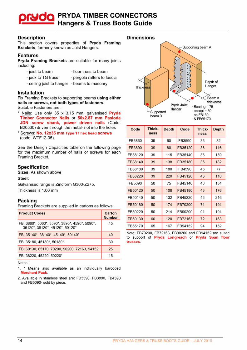
Description This section covers properties of Pryda Framing Brackets, formerly known as Joist Hangers.
Features Pryda Framing Brackets are suitable for many joints including:
- joist to beam - floor truss to beam
- jack to TG truss - pergola rafters to fascia
- ceiling joist to hanger - beams to masonry
Installation Fix Framing Brackets to supporting beams using either nails or screws, not both types of fasteners. Suitable Fasteners are: * Nails: Use only 35 x 3.15 mm, galvanised Pryda
Timber Connector Nails or 50x2.87 mm Paslode JDN screw shank, power driven nails (Code: B20530) driven through the metal- not into the holes
* Screws: No. 12x35 mm Type 17 hex head screws (code: WTF12-35).
See the Design Capacities table on the following page for the maximum number of nails or screws for each Framing Bracket. Specification Sizes: As shown above
Steel:
Galvanised range is Zincform G300-Z275.
Thickness is 1.00 mm
Packing Framing Brackets are supplied in cartons as follows:
Product Codes Carton Number
FB: 3860*, 5060*, 3590*, 3890*, 4590*, 5090*, 35120*, 38120*, 45120*, 50120*
45
FB: 35140*, 38140*, 45140*, 50140* 40
FB: 35180, 45180*, 50180* 30
FB: 60130, 65170, 70200, 90200, 72163, 94152 25
FB: 38220, 45220, 50220* 15
Notes:
1. * Means also available as an individually barcoded Merchant Pack.
2. Available in stainless steel are: FB3590, FB3890, FB4590 and FB5090- sold by piece.
Dimensions
Supporting beam A
Depth ofHanger
Pryda JoistHanger
Thickness
Supported beam B
Bearing = 75except = 60on FB130& FB65170
Beam Athickness
Code Thick- ness
Depth Code Thick- ness
Depth
FB3860 39 60 FB3590 36 82
FB3890 39 80 FB35120 36 116
FB38120 39 115 FB35140 36 139
FB38140 39 138 FB35180 36 182
FB38180 39 180 FB4590 46 77
FB38220 39 220 FB45120 46 110
FB5090 50 75 FB45140 46 134
FB50120 50 108 FB45180 46 176
FB50140 50 132 FB45220 46 216
FB50180 50 174 FB70200 71 194
FB50220 50 214 FB90200 91 194
FB60130 60 120 FB72163 72 163
FB65170 65 167 FB94152 94 152
Note: FB70200, FB72163, FB90200 and FB94152 are suited to support of Pryda Longreach or Pryda Span floor trusses.

PRYDA TIMBER CONNECTORS Hangers & Truss Boots Guide
15 PRYDA HANGERS & TRUSS BOOTS GUIDE – JULY 2010
Design Capacities per Framing Bracket
Framing Bracket Code
Fixing to Supporting
Beam (Beam A)
1.2G+1.5Qf (Dead +Floor Live Load)
Fixing to Supported
Beam (Beam B)
Wind Uplift
(k1 = 1.14)
Design Capacity Nj (kN) for Joint Group:
Design Capacity Nj (kN) for Joint Group:
JD5 JD4 JD3 mm JD5 JD4 JD3 Max.
FB3860 6 Nails 2.9 3.4 4.8 3 nails 2.4 2.8 3.9 4.5
2 Screws 2.1 3.0 4.3 2 screws 3.5 5.0 5.0 5.0
FB3590, FB3890 8 Nails 3.8 4.6 6.4 4 nails 3.2 3.7 5.3 6.0
FB4590, FB5090 4 Screws 4.3 6.1 8.5 2 screws 3.5 5.0 5.0 5.0
FB35120, FB38120 12 Nails 5.3 6.4 8.9 6 nails 4.7 5.7 7.9 9.0
FB45120, FB50120 6 Screws 6.4 9.1 12.8 4 screws 7.1 10.0 10.0 10.0
FB35140, FB38140 16 Nails 7.0 8.4 11.8 8 nails 6.2 7.5 10.6 12.0
FB45140, FB50140 6 Screws 6.4 9.1 12.8 4 screws 7.1 10.0 10.0 10.0
FB35180, FB38180, 20 Nails 8.6 10.3 14.4 10 nails 7.4 8.9 12.4 15.0*
FB45180, FB50180 8 Screws 8.6 12.1 15.0* 6 Screws 10.6 15.0* 15.0* 15.0*
FB38220, FB50220 26 Nails 11.0 13.1 15.0* 13 nails 9.5 11.3 15.0* 15.0*
FB45220 10 Screws 10.1 14.2 15.0* 8 Screws 14.2 15.0* 15.0* 15.0*
FB60130
12 Nails 5.3 6.4 8.9 3 nails 2.4 2.8 3.9 4.5
4 screws 4.3 6.1 8.5 7 nails 5.4 6.6 9.3 10.5
4 screws 7.1 10.0 10.0 10.0
FB65170
18 Nails 7.8 9.3 13.1 6 nails 4.7 5.7 7.9 9.0
6 screws 6.4 9.1 12.8 11 nails 8.1 9.8 13.6 15.0*
6 screws 10.6 15.0* 15.0* 15.0*
FB70200
24 Nails 10.0 11.9 15.0* 3 nails 2.4 2.8 3.9 4.5
10 Screws 10.1 14.2 15.0* 13 nails 9.6 11.6 15.0* 15.0*
7 screws 12.3 15.0* 15.0* 15.0*
FB72163
18 Nails 7.8 9.4 13.0 3 nails 2.4 2.8 3.9 4.5
6 screws 6.4 9.1 12.8 10 nails 7.4 8.9 12.4 15.0*
6 screws 10.6 15.0* 15.0* 15.0*
FB90200
26 Nails 10.8 12.9 15.0* 3 nails 2.4 2.8 3.9 4.5
10 Screws 10.1 14.2 15.0* 13 nails 9.6 11.6 15.0* 15.0*
8 screws 14.2 15.0* 15.0* 15.0*
FB94152
18 Nails 7.8 9.3 13.1 3 nails 2.4 2.8 3.9 4.5
6 screws 6.4 9.1 12.8 10 nails 7.4 8.9 12.4 15.0*
6 screws 10.6 15.0* 15.0* 15.0*
Notes:
1. Beam A = Supporting, Beam B = Supported – see diagram on the previous page.
2. The above tabulated capacities are for a minimum Beam A thickness of 35 mm.
3. Wind uplift capacities apply to designs in accordance with AS/NZS1170:2002..
4. Framing Bracket capacity has been limited to 15.0 kN (shown ‘*’).
5. These capacities apply directly for joints in houses and on secondary beams in other structures. For joints on primary beams in structures other than houses, see General Notes in page 3 for information.
6. For FB60130 and FB65170 brackets, wind uplift – dead load values have been reduced due to a shorter end distance on the supported beam compared to the other brackets.
7. For FB70200 to FB94152, the wind uplift 3 Nails fixing option allows for fixing to the chords only of I-beams or trusses.
8. Multiple Laminated Supporting Beams - Fasteners with longer lengths are required when Joist Hangers are fixed into a multiple laminated supporting beam. For double laminates, use 65 long nails or screws. Alternatively, for double or triple laminated supporting beams, additional fixings may be provided at hanger locations to laminate plies. Seek advice from the Engineer.

PRYDA TIMBER CONNECTORS Hangers & Truss Boots Guide
16 PRYDA HANGERS & TRUSS BOOTS GUIDE – JULY 2010
JOIST HANGERS – HEAVY DUTYHeavy Duty Hanger for Large Sizes, Heavy Loads
JHH.. Hanger Features Pryda Heavy Duty Joist Hangers are designed to support heavily loaded timber beams or two ply trusses on supporting timber beams or girder trusses. All have tongues for fixing to supports to resist twisting and rotation.
Specification Steel: 1.2 mm Zincform® G300-Z275
Packing 10 per carton
Sizes: As below:
6551
122
167
JHH65
177
122
5175
51100
139
202
JHH100JHH75
Dimensions Installation Correct installation of Pryda Heavy Duty Joist Hangers is essential to achieve the design capacities. Use only 35x3.15 mm galvanised Pryda Timber Connector Nails or 50x2.87 mm Paslode JDN screwshank power driven nails (code B20530). Alternatively use No. 12x35 mm Type 17 hex head screws (code: WTF12-35). Do not nail or screw within 30 mm of the ends of the timber beams or within 6 mm of beam edges. Fix the tongue to the underside of supporting beam A with: * minimum 4 fasteners for single laminate Beam A
* minimum 3 fasteners into each laminate for multi-laminate Beam A.
Design Capacities Design capacities per Heavy Duty Hanger are as follows:
JHH65 and JHH75 Hangers
Load Cases Design Capacities (ΦNj) in kN
for Fasteners and Joint Group:
35x3.15 mm Nails
30 nails to Beam A 18 nails* to Beam B
No. 12x35 mm Type 17 Screws
20 screws to Beam A
16 screws to Beam B
JD5 JD4 JD3 JD5 JD4 JD3
1.35G 10.7 12.7 17.8 15.9 22.5 30.0
1.2G + 1.5Qf 12.9 15.4 21.6 19.3 27.2 30.0
1.2G + 1.5Qr 14.4 17.2 24.1 21.5 30.0 30.0
1.2G + Wd 24.4 29.0 30.0 30.0 30.0 30.0
Wind Uplift 13.0 15.4 13.7* 26.0 30.0 30.0
JHH100 Hangers
Load Cases Design Capacities (ΦNj) in kN
for Fasteners and Joint Group:
35x3.15 mm Nails
34 nails to Beam A 22 nails* to Beam B
No. 12x35 mm Type 17 Screws
24 screws to Beam A
18 screws to Beam B
JD5 JD4 JD3 JD5 JD4 JD3
1.35G 12.1 14.4 20.2 19.1 27.4 30.0
1.2G + 1.5Qf 14.6 17.5 24.5 23.1 30.0 30.0
1.2G + 1.5Qr 16.3 19.5 27.3 25.8 30.0 30.0
1.2G + Wd 27.6 30.0 30.0 30.0 30.0 30.0
Wind Uplift 16.1 19.2 17.1* 29.7 28.2 30.0
Notes:
1. Beam A = Supporting Beam, Beam B = Supported Beam
2. Wind capacities – Wind Uplift capacities are based on the AS1720.1:1997 (Amdt No.4 Nov 2002) using k1=1.14, for use in conjunction with AS/NZS1170:2002 loading code
The JD3 capacities (marked *) are based on 11 nails for JHH65 and JHH75 and 14 nails for JHH100 to satisfy end distance requirements (also see Note 3).
3. Supported Beam prone to Splitting - JHH brackets are not recommended to resist uplift loads for supported members using timbers that are prone to splitting (like hardwoods-JD3 joint group) unless additional precautions are taken. These can be in the form of prebored holes or provision of anti-split nailplates at ends of the supported beam.
4. Multiple Laminated Supporting Beams - Fasteners with longer lengths are required when JHH brackets are fixed into a multiple laminated supporting beam. For double laminates, use 65 long nails or screws. Alternatively, for double or triple laminated supporting beams, additional fixings may be provided at hanger locations to laminate plies. Seek advice from the Engineer.
5. The limiting capacity for steel is taken as 30.0 kN
6. Design capacities tabulated above apply directly to joints in houses. For joints on primary beams in structures other than houses, see General Notes in page 3 for information.
7. Design capacities tabulated above apply directly to joints where the depth of Beams A and B are at least Hanger depth + 8 mm. For beams of lesser depth, capacities can be calculated as the tabulated capacity times the number of effective fasteners divided by the maximum numbers of fasteners tabulated above.
Beam A
Beam B

PRYDA TIMBER CONNECTORS Hangers & Truss Boots Guide
17 PRYDA HANGERS & TRUSS BOOTS GUIDE – JULY 2010
SPLIT JOIST HANGERS
Features Pryda Split Joist Hangers are:
suitable for any practical thickness of timber beam.
manufactured from heavy duty (1.6 mm) steel Specification Steel: 1.6 mm Zincform® G300-Z275
Packing per carton
Supplied in cartons of 10, ie. 5 right hand and 5 left hand.
Code & Size: Product code is JHHS. Size is as below
For full capacity, 16Timber ConnectorNails or 8G screwsper hangerinto supportingbeam
For full capacity, 16Timber Connector Nails or 8G screwsper hangerinto supported beamat min. 30 mm from beam end
199
34
52
6217
30 mm min.end distance
for nails
Installation Use only 35 x 3.15 mm galvanised Pryda Timber Connector Nails or 50x2.87 mm Paslode JDN screwshank, power driven nails (Code: B20530) driven though the metal, not through the holes, to fix these connectors. In order to achieve increased capacities, use No. 8 x 25 Type 17 pan head screws through the nail holes. (Note: No. 12 Type 17 screws may be used to achieve higher capacities.)
Do not nail or screw within 30 mm of the ends of the timber beams. For each hanger, drive 16 nails or screws into the supporting beam and 16 nails or screws into the supported beam. Design Capacities Design capacities for a pair of Pryda Split Joist Hangers in houses are:
Load Cases Design Capacities (ΦNj) in kN
for Fasteners and Joint Group:
35x3.15 mm Nails
16 nails to Beam A 16 nails to Beam B
No. 8x25 mm Type 17 Screws
16 screws to Beam A
16 screws to Beam B
JD5 JD4 JD3 JD5 JD4 JD3
1.35G 10.4 12.4 13.3 14.8 20.7 21.7
1.2G + 1.5Qf 12.6 15.0 16.1 17.9 25.1 26.3
1.2G + 1.5Qr 14.1 16.8 17.9 19.9 28.1 29.3
1.2G + Wd or Wind uplift
23.8 28.3 29.8 33.7 40.0 40.0
Notes: 1. Beam A = Supporting Beam, Beam B = Supported Beam
2. Wind capacities – Wind Uplift capacities are based on the AS1720.1:1997 (Amdt No.4 Nov 2002) using k1=1.14, for use in conjunction with AS/NZS1170:2002 loading code The JD3 capacities are based on a reduced number of fasteners to satisfy end distance requirements (also see Note 3).
3. Supported Beam prone to Splitting - JHHS brackets are not
recommended for supported members that are prone to splitting (like hardwoods-JD3 joint group) unless additional precautions are taken. These can be in the form of prebored holes or provision of anti-split nailplates at ends of the supported beam.
4. Multiple Laminated Supporting Beams - Fasteners with longer lengths are required when JHHS brackets are fixed into a multiple laminated supporting beam. For double laminates, use 65 long nails or screws. Alternatively, for double or triple laminated supporting beams, additional fixings may be provided at hanger locations to laminate plies. Seek advice from the Engineer
5. The limiting capacity for steel is taken as 40.0 kN
6. Design capacities apply directly to joints in houses. For joints on primary beams in structures other than houses, see General Notes in page 3 for information.
7. Design capacities tabulated above apply directly to joints where the depth of Beams A and B are at least Hanger depth + 8 mm. For beams of lesser depth, capacities can be calculated as the tabulated capacity times the number of effective fasteners divided by the maximum numbers of fasteners tabulated above.
Supporting Beam (Beam A)
Supported Beam (Beam B)

PRYDA TIMBER CONNECTORS Hangers & Truss Boots Guide
18 PRYDA HANGERS & TRUSS BOOTS GUIDE – JULY 2010
TRUSS BOOTS- MULTI-FIX Metal brackets for truss to truss connections
Girder truss
Truss BootSupported Truss
Bolted Truss Boots
Screw Fixed Truss Boots
Application & Features Pryda Multi-Fix Truss Boots are used to connect roof trusses or other roof members to supporting “girder” trusses and they comprise:
Joist Boots –used for:
* End support of joists and beams
* Support of lightly loaded trusses from girder trusses
Truss Boots – used for support of standard trusses. See also Pryda Heavy Duty Truss Boots. “Multi-fix” means that these connectors can be fixed with bolts or screws, or bolts and screws together. Specification
Type Product Code
Timber Thick.
Bolt Diam.
Application- Support of:
Joist Boot
TBS35 35 12 Small components
TBJ35 35 12 eg: at hip ends
TBJ35/T 35 12 Lightly loaded
TBJ45 45 12 trusses
TBJ70 70 12
Truss Boot
TB35/12 35 12 Standard
TB35/16 35 16/12 trusses
TB45/16 45 16/12
Steel TBS – 1.2 mm G300 –Z275 Galvanised
TBJ & TB – 1.6 mm G300 –Z275 Galvanised
Packing 10 per carton
Size See dimensions following
Note: The TBJ35/T has a tongue to tie the supported truss to the girder. Dimensions Dimensions of Pryda Joist Boots and Truss Boots are:
38/4855
95
7517
TBS35 TBJ35, TBJ35/T, TBJ45
73
95
10315
55
TB35, TB45 TBJ70 Installation Fix Pryda Multi-Fix Truss Boots with fasteners as tabulated below:
Boot Type To Girder To Suppd. Truss
TBS35 2 M12 Bolts or 8 Screws or Bolts +
Screws
4 Screws
TBJ35/45, TBJ70
2 M12 Bolts, or 8 Screws or Bolts +
Screws
1 M12 Bolt or 8 Screws or Bolts +
Screws
TB35/12 2 M12 Bolts, or 8 Screws or Bolts +
Screws
2 M12 Bolts or 12 Screws or Bolts +
Screws
TB35/16, TB45/162 M16 Bolts, or 8 Screws or Bolts +
Screws
2 M12 Bolts or 12 Screws or Bolts +
Screws
Notes:
1. M12 or ½ inch diameter must be fitted with nuts and 55 mm diameter or 50x50 mm square by 3 mm thick washers. M16 or 5/8 inch diameter bolts must be fitted with nuts and 65 mm diameter or 57x57 mm square by 4 mm thick washers. See Pryda Bolt Kits
2. Screws are No.12 x 35 mm Type 17 hex head screws
38/4855
95
75
50
17
38/4855
95
17 75
115

PRYDA TIMBER CONNECTORS Hangers & Truss Boots Guide
19 PRYDA HANGERS & TRUSS BOOTS GUIDE – JULY 2010
Installation of Pryda Multi-Fix Truss Boots:
Bolts Only Installation:
1. Fit the Boot flush with the bottom of the girder bottom chord and tack fix with two nails or screws. Drill the bolt hole and fit the bolt with the nut and washer on the face opposite to the boot.
2. Sit the incoming member into the boot and fix it in place. The clearance between the end of the incoming member and the face of the girder truss chord should not exceed 5 mm, preferably 0 mm. Drill the bolt hole (TBJ and TB types only) and fit the bolt(s) and nut(s).
3. Hammer apply anti-split Claw nailplates on the girder truss chord on both faces and both sides of the Boot, ie: 4 nailplates of:
Chord width (mm) 90 120,140 170,190
Anti-split Plate Size 3C2 4C2 6C2
Note: Anti-split Claw nailplates are NOT required for boots fixed with M12 bolts into timbers that are not prone to splitting.
Anti-split nailplateson both faces of girder and both sides of boot Truss Boot
Supported truss
M12 bolts, with 50x50 mm square by 3 mm washers on back faceexcept on TB35/16 or TB45/16, use M16bolts with 57x57 mm square by 4 mm washers on back face.
Bolts Only Installation Detail 1
Supported truss
M12 bolts
Truss Boot
Round or square washer of size required for bolt
size (see Installation)
Bolts Only Installation Detail 2
Screws Only Installation:
1. If the girder truss is comprised of two or more laminates (ie: a “double” or “triple” girder), the laminates must be fixed together using one of the details specified in Fixing Details For Double or Triple Girders opposite.
2. Fit the Boot flush with the bottom of the girder bottom chord and tack fix with two screws. Drive the remaining screws
3. Sit the incoming member into the boot and fix it in place. The clearance between the end of the incoming member and the face of the girder truss chord should not exceed 5 mm, preferably 0 mm. Drive screws into all holes.
Note that anti-split nailplates are not required for Screws Only fixing.
Bolts & Screws Installation:
1. Install the Truss Boot and supported truss as per the Bolts Only method.
2. Drive the screws into all screw holes.
Anti-split nailplates (if necessary) on both faces of girder and both sides of boot

PRYDA TIMBER CONNECTORS Hangers & Truss Boots Guide
20 PRYDA HANGERS & TRUSS BOOTS GUIDE – JULY 2010
Fixing Details For Double & Triple Girders- Screws Only Fixing Option
DOUBLE GIRDERS 2@ 35 Girder Laminations – Preferred Fixing Detail
Alternative Fixing Detail
2@ 45 Girder Laminations – Preferred Fixing Detail
Alternative Fixing Detail
TRIPLE GIRDERS 3@ 35 or 3@ 45 mm Laminations – Preferred Fixing
Alternative Fixing Detail
Notes
1. Nails at the Truss Boot are to be spaced 70mm (min) apart along the grain and 40 mm (min) apart across the grain. They should be as close to the Truss Boot as practical, but not further away than the depth of the member.
2. Use the details for 35 mm laminates for timber thickness between 35 and 40 mm, and the 45 mm details for timber thickness between 41 and 50 mm.
3. All screws are to be No. 12 x35 mm Type 17 hex. head or No 12 x65 mm Type 17 hex head.
4. For all double and triple girder trusses, the chords (top and bottom) and webs are to be nailed at:
Timber Width Nail Rows & Maximum Spacing
Up to 100 mm 2 rows at 500 mm
101 - 200 mm 2 rows (staggered) at 250 mm
201 - 300 mm 3 rows (staggered) at 250 mm
25 mm
25 mm
250 mm 250 mm
Nails staggered
500 mm
25 mm
25 mm
25 mm
250 mm 250 mm 250 mm
25 mm
250 mm 250 mm
101 - 200 mm Chords or Webs
Timber Up to 100 mm Chords or Webs
201 -300 mm Chords or Webs
250 mm 250 mm
250 mm 250 mm
65 mm Self drilling woodscrews into the girder
Truss Boot
8@ 35 mm Self drilling wood screws+ 10@ 65x2.87 mm nails into girder
Truss Boot
65 mm Self drilling wood screws+ 4@ 90x3.33 mm nails into girder
Truss Boot
35 mm Self drilling wood screws+ 8@ 90x3.33 mm nails into girder
Truss Boot
35 mm Self drilling wood screws+ 2@ M12 bolts with 50x50x3 mm square washers on timber side only
Truss Boot
35 mm Self drilling wood screws+ 18@ 90x3.33 mm nails:(12 to front lamination, 6 to back lamination)
Truss Boot

PRYDA TIMBER CONNECTORS Hangers & Truss Boots Guide
21 PRYDA HANGERS & TRUSS BOOTS GUIDE – JULY 2010
Design Capacities for Pryda Truss Boots Determine Truss Boot capacities in the following manner: For downward loads: design capacity is the lesser of the values in Table TB1 (at Girder truss) and Table TB2 (at supported truss) for the corresponding load case. For wind uplift: design capacity is the lesser of the G-Wu values in Table TB1 (at Girder truss) and Table TB3 (at supported truss)
Table TB1: Girder Truss Capacity (Downward and Uplift – due to fasteners)
Boot Load Design Capacity ΦNj (kN) - Joint Group:
Code Case JD3 JD4
Minimum Girder Thickness (mm)
35 45 70 35 45 70
Bolts Only
TBS35
G 6.1 7.8 9.1 4.5 5.8 7.6
G + Qr 8.2 10.6 12.2 6.1 7.8 10.2
G + Wd or G-Wu
12.2 13.2* 13.2* 9.0 11.5 13.2
TBJ35, TBJ35/T TBJ45
TB35/12 TBJ70
G 6.1 7.8 9.1 4.5 5.8 7.6
G + Qr 8.2 10.6 12.2 6.1 7.8 10.2
G + Wd G-Wu
12.2 15.7 17.6* 8.9 11.6 15.1
TB35/16 TB45/16
G 8.1 10.5 14.0 6.0 7.7 10.8
G + Qr 11.0 14.1 18.8 8.1 10.4 14.6
G + Wd 16.3 20.5 20.5 11.9 15.4 20.5
G-Wu 16.3 20.0* 20.0* 11.9 15.4 20.0*
Screws Only
TBS35
G 14.1 14.1 14.1 10.0 10.0 10.0
G + Qr 19.1 19.1 19.1 13.5 13.5 13.5
G + Wd 20.0* 20.0* 20.0* 20.0* 20.0* 20.0*
G - Wu 15.0* 15.0* 15.0* 15.0* 15.0* 15.0*
All other truss Boots
G 14.1 14.1 14.1 10.0 10.0 10.0
G + Qr 19.1 19.1 19.1 13.5 13.5 13.5*
G + Wd 24.0* 24.0* 24.0* 20.1 20.1 20.1
G-Wu 20.0* 20.0* 20.0* 20.0* 20.0* 20.0*
Bolts & Screws
TBS35
G 20.0 22.0 20.0 14.5 15.8 17.6
G + Qr 20.0 20.0 20.0 19.6 20.0 20.0
G + Wd 20.0 20.0 20.0 20.0 20.0 20.0
G - Wu 15.0* 15.0* 15.0* 15.0* 15.0* 15.0*
TBJ35 TBJ35/T TBJ45
TB35/12 TBJ70
G 20.2 22.0 25.0 14.5 15.8 17.6
G + Qr 25.0 25.0 25.0 19.6 21.3 23.7
G + Wd 25.0 25.0 25.0 25.0 25.0 25.0
G-Wu 20.0* 20.0* 20.0* 20.0* 20.0* 20.0*
TB35/16 TB45/16
G 22.2 25.0 25.0 14.5 15.8 17.6
G + Qr 25.0 25.0 25.0 19.6 21.3 23.7
G + Wd 25.0 25.0 25.0 25.0 25.0 25.0
G - Wu 20.0* 20.0* 20.0* 20.0* 20.0* 20.0*
Note: For Screws Only capacities for 70 mm girder trusses (double girders), the laminates of the girder truss must be fixed together in accordance with the Fixing Details For Double & Triple Girders requirements on pages 17 and18.
Table TB2: Supported Truss Capacity (Downward – due to Bearing + Fasteners )
Truss Load Design Capacity ФNj (kN) - Joint Group:
Boot Case JD3 JD4
Code Fixing Option:
Bolts only
Screws only
Bolts + Screws
Bolts only
Screws only
Bolts + Screws
TBS35
G NA 20.0* NA NA 15.1 NA
G + Qr NA 20.0* NA NA 20.0* NA
G + Wd NA 20.0* NA NA 20.0* NA
TBJ70
G 25.0* 25.0* 25.0* 21.0 25.0* 25.0*
G + Qr 25.0* 25.0* 25.0* 25.0* 25.0* 25.0*
G + Wd 25.0* 25.0* 25.0* 25.0* 25.0* 25.0*
TBJ35 TBJ35/T
G 13.6 21.8 24.9 9.4 15.1 17.4
G + Qr 21.5 25.0* 25.0* 14.8 22.5 25.0*
G + Wd 25.0* 25.0* 25.0* 17.0 25.0* 25.0*
TBJ45
G 17.6 25.0* 25.0* 12.1 17.3 20.2
G + Qr 25.0* 25.0* 25.0* 19.2 25.0* 25.0*
G + Wd 25.0* 25.0* 25.0* 25.0 25.0* 25.0*
TB35/12
G 16.0 25.0* 25.0* 11.2 18.4 22.4
G + Qr 24.8 25.0* 25.0* 17.2 25.0* 25.0*
G + Wd 25.0 25.0* 25.0* 20.6 25.0* 25.0*
TB35/16
G 17.9 25.0* 25.0* 12.5 18.4 23.8
G + Qr 25.0* 25.0* 25.0* 19.0 25.0* 25.0*
G + Wd 25.0* 25.0* 25.0* 23.3 25.0* 25.0*
TB45/16
G 23.1 25.0* 25.0* 16.2 20.5 25.0*
G + Qr 25.0* 25.0* 25.0* 25.0* 25.0* 25.0*
G + Wd 25.0* 25.0* 25.0* 25.0* 25.0* 25.0*
Notes:
1. Load case symbols are: (refer page 4 for descriptions) G = 1.35G G+Qr = 1.2G+1.5Qr G+Wd = 1.2G+Wd G-Wu = Wind uplift
2. Girder timber thicknesses are minimums. Supported truss thicknesses are minimums for bolt capacity and maximums (3 mm tolerance for two nailplates) for fitting the timber into the boot. 70 mm thickness can be made from 2@ 35 mm trusses, nail or bolt laminated together as specified by the truss designer.
3. Bearing + fasteners capacities above apply to standard heel joints with a 10 mm minimum square cut or non-heel ends of cut-off and mono trusses.
4. The tabulated capacities apply directly to Pryda Truss Boot joints in houses or on secondary trusses or beams in other structures. For joints on primary trusses in structures other than houses, see General Notes in page 3 for information.
5. For other design conditions, contact a Pryda design office.
6. The capacities with ‘*’ are governed by steel strength of the truss boot or screw or bolt bearing on steel.
7. For designs using the 2010 edition of AS1720, the capacities derived for Bolts Only may be increased by 10%.

PRYDA TIMBER CONNECTORS Hangers & Truss Boots Guide
22 PRYDA HANGERS & TRUSS BOOTS GUIDE – JULY 2010
Table TB3: Supported Truss Capacity
(Uplift– due to fasteners )
Boot Thick- Fixing Des.Cap. ΦNj (kN)
Code ness Method Wind Uplift (G-Wu)
k1 = 1.14
(mm) JD3 JD4
TBS35 35 6 screws 15.0* 13.5
TBJ35 TBJ35/T
35
8 screws 20.0* 18.0
Bolt only 4.9 3.6
Bolt + screws 20.0* 20.0*
TBJ45 45
8 screws 20.0 18.0
Bolt only 6.3 4.6
Bolt + screws 20.0* 20.0*
TBJ70 70
6 screws 18.0 13.5
Bolt only 6.3 4.6
Bolt + screws 20.0* 20.0*
TB35/12 35
12 screws 20.0* 20.0*
Bolt only 9.8 7.2
Bolt + screws 20.0* 20.0*
TB35/16 TB45/16
45
12 screws 20.0* 20.0*
Bolt only 13.0 9.6
Bolt + screws 20.0* 20.0*
Notes:
1. For wind uplift, take the lower of the capacities for the supported truss and girder, ie: look up both tables.
2. Wind Uplift capacities are based on the AS/NZS1170:2002 code, using k1=1.14.
3. The capacities with ‘*’ are governed by steel strength of the truss boot.
Examples The following are examples of determining a suitable Pryda Truss Boot based on the Design Capacities tables. Example 1: Design data: Supported truss thickness 35 mm Supported truss timber MGP12 dry pine (JD4) Girder truss thickness 45 mm Girder truss timber F17 dry hardwood (JD3) Preferred fixing method Screws Design Loads:
Load case 1.35G G + Qr G + Wd G – Wu
Load (kN) 3.5 6.8 5.4 1.6 Try TBS35: - which suits the 35 mm supported truss:
Looking up tables: TB1(JD3, 45) and TB2(JD4) for: Screws only -
Load Case TB1 TB2 Design Load Suit
G = 14.1 15.1 14.1 3.5 OK
G + Qr = 19.1 20.0 19.1 6.8 OK
G + Wd = 20.0 20.0 20.0 5.4 OK Uplift: Looking up Table TB3 for JD4 – Screws Only:
Load Case TB1 TB3 Design Load Suit
G - Wu 15.0 13.5 13.5 1.6 OK Therefore, a TBS35 is suitable.
Example 2: Design data: Supported truss thickness 35 mm Supported truss timber MGP12 dry pine (JD4) Girder truss thickness 70 mm Girder truss timber F17 dry hardwood (JD3) Preferred fixing method Bolts Design Loads: 1.35G 1.5 kN 1.2G+1.5Qr 4.8 kN 1.2G+Wd 7.3 kN 0.9G-Wu (Wind uplift) -11.9 kN
Try TBJ35: - which suits the 35 mm supported truss:
Looking up tables TB1(JD3, 70) and TB2 (JD4) for TBJ35, Bolts only:
Load Case TB1 TB2 Design Load Suit
G = 9.1 9.4 9.1 1.5 OK
G + Qr = 12.2 14.8 12.2 4.8 OK
G + Wd = 17.6 17.0 17.0 7.3 OK
Uplift: Looking up Table TB3 for TBJ35, JD4 – Bolt Only and TB1, TBJ35, JD3, Bolts only
Load Case TB1 TB3 Design Load Suit
G - Wu 17.6 3.6 3.6 11.9 NS Try screws only – for wind uplift:
Load Case TB1 TB3 Design Load Suit
G - Wu 20.0 18.0 18.0 11.9 OK
Therefore, a TBJ35 is suitable with screw fixing of supported truss.
PRYDA TIMBER CONNECTORS Hangers & Truss Boots Guide
23 PRYDA HANGERS & TRUSS BOOTS GUIDE – JULY 2010
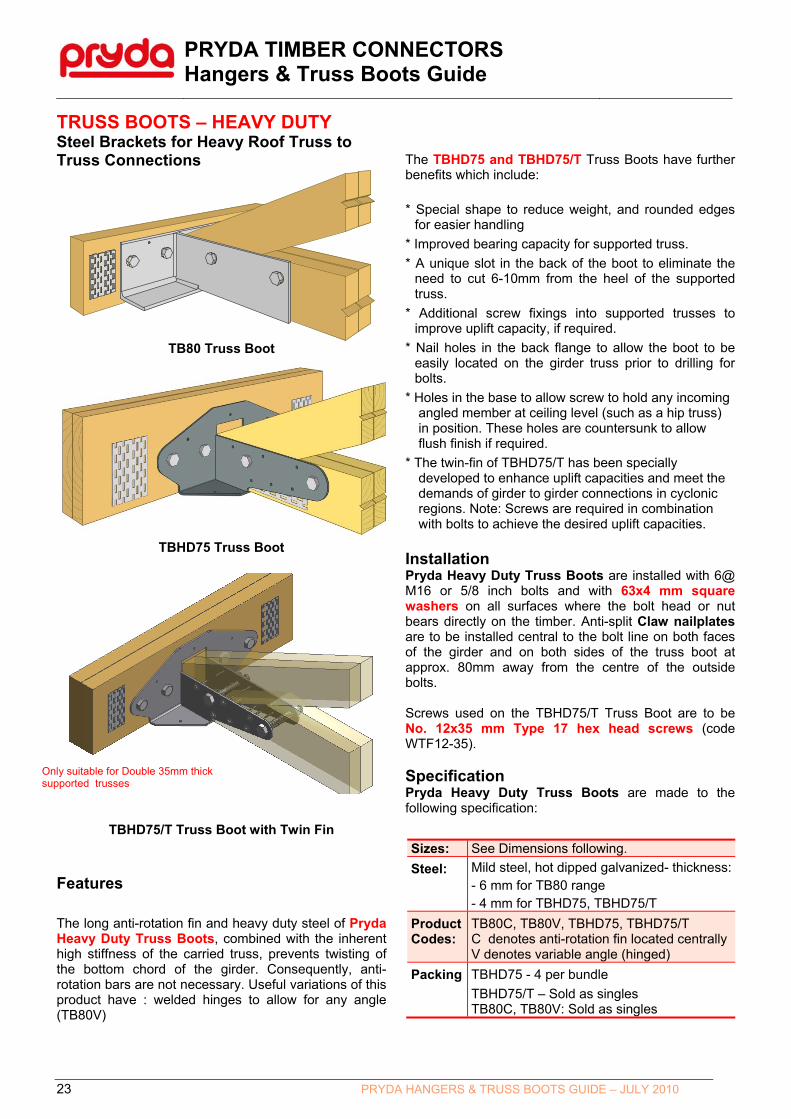
TRUSS BOOTS – HEAVY DUTYSteel Brackets for Heavy Roof Truss to Truss Connections
TB80 Truss Boot
TBHD75 Truss Boot
TBHD75/T Truss Boot with Twin Fin Features
The long anti-rotation fin and heavy duty steel of Pryda Heavy Duty Truss Boots, combined with the inherent high stiffness of the carried truss, prevents twisting of the bottom chord of the girder. Consequently, anti-rotation bars are not necessary. Useful variations of this product have : welded hinges to allow for any angle (TB80V)
The TBHD75 and TBHD75/T Truss Boots have further benefits which include:
* Special shape to reduce weight, and rounded edges for easier handling
* Improved bearing capacity for supported truss.
* A unique slot in the back of the boot to eliminate the need to cut 6-10mm from the heel of the supported truss.
* Additional screw fixings into supported trusses to improve uplift capacity, if required.
* Nail holes in the back flange to allow the boot to be easily located on the girder truss prior to drilling for bolts.
* Holes in the base to allow screw to hold any incoming angled member at ceiling level (such as a hip truss) in position. These holes are countersunk to allow flush finish if required.
* The twin-fin of TBHD75/T has been specially developed to enhance uplift capacities and meet the demands of girder to girder connections in cyclonic regions. Note: Screws are required in combination with bolts to achieve the desired uplift capacities.
Installation Pryda Heavy Duty Truss Boots are installed with 6@ M16 or 5/8 inch bolts and with 63x4 mm square washers on all surfaces where the bolt head or nut bears directly on the timber. Anti-split Claw nailplates are to be installed central to the bolt line on both faces of the girder and on both sides of the truss boot at approx. 80mm away from the centre of the outside bolts. Screws used on the TBHD75/T Truss Boot are to be No. 12x35 mm Type 17 hex head screws (code WTF12-35). Specification Pryda Heavy Duty Truss Boots are made to the following specification:
Sizes: See Dimensions following.
Steel: Mild steel, hot dipped galvanized- thickness:- 6 mm for TB80 range - 4 mm for TBHD75, TBHD75/T
Product Codes:
TB80C, TB80V, TBHD75, TBHD75/T C denotes anti-rotation fin located centrally V denotes variable angle (hinged)
Packing TBHD75 - 4 per bundle
TBHD75/T – Sold as singles TB80C, TB80V: Sold as singles
Only suitable for Double 35mm thick supported trusses

PRYDA TIMBER CONNECTORS Hangers & Truss Boots Guide
24 PRYDA HANGERS & TRUSS BOOTS GUIDE – JULY 2010
Fixing into Girder Truss: 4/M16 bolts + washers
TBHD75/T Suitable for 2/35 supported trusses only, to achieve large tie-down capacities
Dimensions The dimensions of Heavy Duty Truss Boots are :
100
75
90
7525
7525
150
25
General Dimensions
25
65
65
225450
285
225450
225450
Hinge
TB80C
TB80C45/R TB80V
196365
274
TBHD75
Applications
Bottom chord of girder truss, min. depth = 130 mm
Anti-split plates arerequired on both facesof the girder truss chord and on both sides of the Truss Boot
Pryda Heavy Duty Truss Boot fixed withM16 or 5/8 inch bolts with 63 mm squarewashers on the back faces only-* girder truss - 4 bolts* supported truss - 2 bolts
Anti-rotation legof Truss Boot
Carried truss
90
88
2464
15081
69
365
76
24
75
45
76
45
24
274
160
24
Window for flushfinish between girderand supported truss
90
TBHD75 Dimensions
Fixing into Supported Truss: 2/M16 bolts + 6 screws on each arm (12 screws in total).

PRYDA TIMBER CONNECTORS Hangers & Truss Boots Guide
25 PRYDA HANGERS & TRUSS BOOTS GUIDE – JULY 2010
Design Capacities for TBHD75 (also applicable for TB80C and TB80V)
Table‐ JD4
Girder Truss bottom Chord using JD4 Joint Group (eg: MGP12, MGP15, Hychord, E‐beam etc) with a minimum 130mm depth.
Bolts Only Bolts+Screws Bolts Only Bolts+Screws Bolts Only Bolts+Screws
35 12.0 16.2 6.9 14.9 12.0 16.2 9.6 20.9 12.0 16.2 13.0 24.0
2/35 12.0 16.2 13.8 21.8 12.0 16.2 19.1 24.0 12.0 16.2 24.0 24.0
35 15.3 20.8 6.9 14.9 15.3 20.8 9.6 20.9 15.3 20.8 13.0 29.0
2/35 15.3 20.8 13.8 21.8 15.3 20.8 19.1 30.0 (2) 15.3 20.8 26.1 30.0 (2)
35 15.4 (1) 25.3 (1) 6.9 14.9 17.3 (1) 28.5 (1) 9.6 20.9 21.6 29.1 13.0 29.0
2/35 21.6 29.1 13.8 21.8 21.6 29.1 19.1 30.0 (2) 21.6 29.1 26.1 30.0 (2)
35 15.4 (1) 25.3 (1) 6.9 14.9 17.3 (1) 28.5 (1) 9.6 20.9 23.3 31.4 13.0 29.0
2/35 23.3 31.4 13.8 21.8 23.3 31.4 19.1 30.0 (2) 23.3 31.4 26.1 30.0 (2)
Table‐ JD3
Girder Truss bottom Chord using JD3 Joint Group (eg: F17, e‐beam+ etc) with a minimum 130mm depth.
Bolts Only Bolts+Screws Bolts Only Bolts+Screws Bolts Only Bolts+Screws
35 15.4 (1) 22.0 6.9 14.9 16.3 22.0 9.6 20.9 16.3 22.0 13.0 29.0
2/35 16.3 22.0 13.8 21.8 16.3 22.0 19.1 30.0 (2) 16.3 22.0 26.1 30.0 (2)
35 15.4 (1) 25.3 (1) 6.9 14.9 17.3 (1) 28.3 9.6 20.9 20.9 28.3 13.0 29.0
2/35 20.9 28.3 13.8 21.8 20.9 28.3 19.1 30.0 (2) 20.9 28.3 26.1 30.0 (2)
35 15.4 (1) 25.3 (1) 6.9 14.9 17.3 (1) 28.5 (1) 9.6 20.9 25.6 (1) 37.7 13.0 29.0
2/35 27.9 37.7 13.8 21.8 27.9 37.7 19.1 30.0 (2) 27.9 37.7 26.1 30.0 (2)
35 15.4 (1) 25.3 (1) 6.9 14.9 17.3 (1) 28.5 (1) 9.6 20.9 25.6 (1) 37.7 13.0 29.0
2/35 27.9 37.7 13.8 21.8 27.9 37.7 19.1 30.0 (2) 27.9 37.7 26.1 30.0 (2)
45
2/35
3/35
1.2G+1.5Q(Dead+Live)
Wind Uplift 1.35G (Dead Only)
1.2G+1.5Q(Dead+Live)
Wind Uplift
35
Girder Truss
Thickness
(mm)
Supported
Truss
Thickness
Design Capacities (kN) for varying Load Cases and Supported Truss Joint Groups
Supported Truss = JD5 Supported Truss = JD4 Supported Truss = JD3
1.35G (Dead Only)
1.2G+1.5Q(Dead+Live)
Wind Uplift 1.35G (Dead Only)
3/35
1.2G+1.5Q(Dead+Live)
Wind Uplift 1.35G (Dead Only)
1.2G+1.5Q(Dead+Live)
35
45
2/35
Girder Truss
Thickness
(mm)
Supported
Truss
Thickness
Design Capacities (kN) for varying Load Cases and Supported Truss Joint Groups
Supported Truss = JD5 Supported Truss = JD4 Supported Truss = JD3
1.35G (Dead Only)
1.2G+1.5Q(Dead+Live)
Wind UpliftWind Uplift 1.35G (Dead Only)
Notes:
(1) The above capacities (except Bolts+Screws) are valid for TB80C and TB80V truss boots. See note (3) for steel limits.
(2) The values with a superscript (1) refers to the design capacities that are limited by bearing- i.e crushing of the supported truss against the seat of the truss boot.
(3) The values (30 kN) with a superscript (2) refers to the capacities that are limited by steel strength of TBHD75 in uplift. The The limiting steel value for downward loading is 40 kN. The limiting steel value for TB80V equals 26 kN (downward loads) and 18.0 kN (uplift).
(4) 2/35 refers to 35mm thick double laminated truss and 3/35 refers to 35mm thick triple laminated truss.
(5) The values in the table apply directly for joints in houses. Refer General Notes in page 4 for advice on how the values should be reduced for other building types.
(6) The values related to 1.35G (Dead only) load case should be checked against reactions arising from 1.35G load case. Similarly 1.2G+1.5Q (Dead + Roof Live) capacities should be checked against factored reactions from 1.2G+1.5Q load case.
(7) A 120mm deep bottom chord for girder trusses may be used when supporting concrete tile roofs in low wind areas (upto N2 wind class) where wind uplift is not critical or when the truss boot is located at a panel point.
(8) It is important to use the specified washer (63 x 5 square) against the timber face to achieve full capacity of M16 bolts.
(9) For designs using the 2010 edition of AS1720, the capacities derived for Bolts Only may be increased by 10%.

PRYDA TIMBER CONNECTORS Hangers & Truss Boots Guide
26 PRYDA HANGERS & TRUSS BOOTS GUIDE – JULY 2010
Design Capacities for the Twin Fin TBHD75/T (suitable only for double 35mm supported trusses)
Table‐ JD4
Girder Truss bottom Chord using JD4 Joint Group (eg: MGP12, MGP15, Hychord, E‐beam etc) with a minimum 130mm depth.
Bolts Only Bolts+Screws Bolts Only Bolts+Screws Bolts Only Bolts+Screws
35 2/35 12.0 16.2 13.8 24.0 (3) 12.0 16.2 19.1 24.0 (3) 12.0 16.2 24.0 (3) 24.0 (3)
45 2/35 15.3 20.8 13.8 29.8 15.3 20.8 19.1 30.8 (3) 15.3 20.8 26.1 30.8 (3)
2/35 2/35 21.6 29.1 13.8 29.8 21.6 29.1 19.1 41.8 21.6 29.1 26.1 43.1 (3)
3/35 2/35 23.3 31.4 13.8 29.8 23.3 31.4 19.1 41.8 23.3 31.4 26.1 46.5 (3)
Table‐ JD3
Girder Truss bottom Chord using JD3 Joint Group (eg: F17, e‐beam+ etc) with a minimum 130mm depth.
Bolts Only Bolts+Screws Bolts Only Bolts+Screws Bolts Only Bolts+Screws
35 2/35 16.3 22.0 13.8 29.8 16.3 22.0 19.1 32.6 (3) 16.3 22.0 26.1 32.6 (3)
45 2/35 20.9 28.3 13.8 29.8 20.9 28.3 19.1 41.8 20.9 28.3 26.1 41.9 (3)
2/35 2/35 27.9 37.7 13.8 29.8 27.9 37.7 19.1 41.8 27.9 37.7 26.1 50.0 (2)
3/35 2/35 27.9 37.7 13.8 29.8 27.9 37.7 19.1 41.8 27.9 37.7 26.1 50.0 (2)
Girder Truss
Thickness
(mm)
Supported
Truss
Thickness
Design Capacities (kN) for varying Load Cases and Supported Truss Joint Groups
Supported Truss = JD5 Supported Truss = JD4 Supported Truss = JD3
1.35G (Dead Only)
1.2G+1.5Q(Dead+Live)
Wind Uplift 1.35G (Dead Only)
1.2G+1.5Q(Dead+Live)
Wind Uplift 1.35G (Dead Only)
1.2G+1.5Q(Dead+Live)
Wind Uplift
Notes:
(1) 2/35 refers to 35mm thick double laminated truss and 3/35 refers to 35mm thick triple laminated truss.
(2) The values (50 kN) with a superscript (2) refers to the capacities that are limited by steel strength of TBHD75/T in uplift. The limiting steel value for ''down-loading' is 50 kN.
(3) Uplift Capacities - The values with a superscript (3) are limited by 4/M16 bolt fixings in girder truss. U.N.O in Notes 2 and 3, fixing into supported truss governs for UPLIFT.
(4) The values in the table apply directly for joints in houses. Refer General Notes in page 4 for advice on how the values should be reduced for other building types.
(5) The values related to 1.35G (Dead only) load case should be checked against reactions arising from 1.35G load case. Similarly 1.2G+1.5Q (Dead + Roof Live) capacities should be checked against factored reactions from 1.2G+1.5Q load case.
(6) A 120mm deep bottom chord for girder trusses may be used when supporting concrete tile roofs in low wind areas (upto N2 wind class) where wind uplift is not critical or when the truss boot is located at a panel point.
(7) It is important to use the specified washer (63 x 5 square) against the timber face to achieve full capacity of M16 bolts. Required only against Girder truss when using TBHD75/T.
(8) For designs using the 2010 edition of AS1720, the capacities derived for Bolts Only may be increased by 10%.

PRYDA TIMBER CONNECTORS Hangers & Truss Boots Guide
27 PRYDA HANGERS & TRUSS BOOTS GUIDE – JULY 2010
Heavy Duty Truss Boot Uplift Reinforcement Where necessary, TB80 and TBHD75 truss boots can be reinforced to provide additional uplift resistance as follows:
Pryda HD Truss Boot
50x3 mm steel overstrap- ensure full bearing on top chord
140min.
Note: The boltthrough theoverstrap mustbe installedthrough or abovethe heel jointnailplates.
For 35 mm Supported Trusses
140min.
Pryda HD Truss Boot
50x3 mm steel overstrap- ensure full bearing on top chord Note: The bolt
through theoverstrap mustbe installedthrough or abovethe heel jointnailplates.
For 70 mm Supported Trusses
Bolt Kits For Truss Boots Hot dipped galvanised Kits of bolts, nuts and washers are
available to suit all bolt fixed truss boots. Details are:
Product Code:
OBK312 OBK316 OBK816
To suit: TBS35/45, TBJ35/45/70
TB35/12
TB35/16, TB45/16
TB80, TBHD75
Packed: 80 80 60
Bolts (mm):
2@ 12x65 2@ 12x100
2@ 12x65 2@ 16x110
6@ 16x110
Washers (square):
4@ 55x3 2@ 55x3 2@ 63x5
6@ 63x5
UPLIFT CAPACITY (kN) for Timber Joint Group & Strength Group:
Supp. Thick.
J4 (S6)
J3 (S4)
J2 (S3)
JD5 (SD7)
JD4 (SD6)
JD3 (SD5)
35 11.5 18.3 25.2 13.9 18.3 25.2
70 20.6 31.4 35.0 21.4 26.7 35.0
Notes:
1. The capacities for details with the overstrap, are limited by either 4@ M16 bolts bearing on carrying truss or based on Details TD-06/TD-07 published by TRADAC (December 2000). For these tabulated capacities, the bolt through the over-strap must be installed through or above the heel joint nailplates.
2. The bottom chord of carrying (girder) truss shall be a minimum of 130 mm deep. A 120mm deep bottom chord for girder trusses may be used provided the truss boot is located at a panel point.
3. Fix the over-angle to the TB80 or TBHD75 with the M16 H.S bolt and nut used for fixing the Truss Boot to the supported truss. Install 63x5 mm square washers where the bolt or nut bears directly onto timber.
130 min
130 min

PRYDA TIMBER CONNECTORS Hangers & Truss Boots Guide
28 PRYDA HANGERS & TRUSS BOOTS GUIDE – JULY 2010
HIP SUPPORT BRACKETS (HSB)
Supports hip trusses/rafters at girder truss junctions
Application & Features Hip Support Brackets (HSB) are used to connect hip trusses or hip rafters to supporting “girder” trusses at a girder to girder junction. Design Capacities
1. Table 1 - Downward Loads
Joint Group of
Supporting Truss
HSB Capacity (kN) Fixing: 4/No.12 Type 17 screws into supporting
truss
HSB+TB35 Capacity (kN)
Fixing: 8/No.12 Type 17 screws into supporting
truss
1.35G 1.2G + 1.5Qr 1.35G 1.2G + 1.5Qr
JD4 4.8 6.5 9.3 12.6
JD3 6.8 9.2 13.2 17.8
2. Table 2 -Uplift Loads
Minimum Joint Group
Uplift Capacity (kN)
HSB HSB + TB35
JD5 1.5 13.2
JD4 2.0 18.7
JD3 2.5 20.0
Steel 3.0 mm G300 – Galvanised
Packing 50 per carton
Size 75 x 68 x 103 x 3mm thick
Notes(i) The HSB+TB35 capacity in the above
table is the same as the TB35 capacity by itself as it is based on the 8/No.12 Type 17 screws into the supporting truss. These values therefore relate to the maximum combined load that can be resisted (i.e. load from hip truss + supported girder)
(ii) Screws with longer lengths are required when HSBs are fixed into multiple laminated trusses. For double laminates, use 65mm long screws into supporting truss.
Notes:(i) The Uplift Capacity of HSB is based on
1/No.12 x 35mm Type 17 screw in withdrawal. This value relates to the maximum uplift reaction of the hip truss that can be resisted. The uplift capacity may be enhanced using alternative tie-down fixings like cyclone straps etc.
(ii) The HSB+TB35 capacity has the same meaning as in Table 1.