ps-3025sh install v110tlgplp jan0802 - autostart -...
TRANSCRIPT

Installation Guide TABLE OF CONTENTS
TABLE OF CONTENTS..................................................1
INTRODUCTION ............................................................2
WHAT’S INCLUDED .....................................................2
BEFORE YOU GET STARTED… ...................................2
INSTALLATION POINTS TO REMEMBER.................2
PS-3025 SH – FEATURES LIST.....................................3
HARNESS DESCRIPTION .............................................4
WIRING DIAGRAM .......................................................6
TRANSMITTER FUNCTIONS .......................................7
LEARNING A TRANSMITTER .....................................7
THE PROGRAMMING ASSISTANCE BUTTON .........7
VALET OPERATION......................................................7
To get into Valet Mode:................................................7
To get out of Valet Mode:.............................................8
MULTI-SPEED TACH LEARNING...............................8
PROGRAMMING OPTIONS ..........................................8
2nd IGN / ACC / CRANK RELAY OUTPUT ................10
PROGRAMMABLE FEATURES..................................10
Lock Pulse Duration ...................................................10
Vehicle Type – Gas or Diesel .....................................10
Horn Confirmation......................................................10
SAFE START.............................................................11
Idle Mode....................................................................11
To activate the Idle Mode: ..........................................11
Cold Weather Mode....................................................11
Ignition-Controlled Door Locks .................................11
Smart Ignition Locks ..................................................11
Engine Running Confirmation....................................11
Smart Rearm...............................................................11
Secure Lock ................................................................11
Smart Secure Lock......................................................12
Key Sense ...................................................................12
Starter Disable ............................................................12
Priority Door Access ..................................................12
AUX 2 –Timed Output ...............................................13
Headlight Illumination............................................13
Remote-Activated Dome Light Supervision...........13
Horn Chirp Timing .....................................................14
AUX 3 – TRUNK or Sunroof control ........................14
TRUNK output with Disarm / Rearm pulse ...............14
Programmable External Trigger .................................14
HOME VALET .......................................................15
GROUND OUTPUT ......................................................15
PANIC MODE (in order to be available, this option must
be programmed)..............................................................15
QUICK LOCKOUT ....................................................15
MULTI-CAR OPERATION ..........................................15
RESETTING THE MODULE........................................16
EVENTS LOGGING and PLAYBACK.........................16
Start Failure Codes via Parking Lights: ......................16
Events playback:.........................................................16
DIAGNOSTICS - PARKING LIGHTS .........................17
TESTING .......................................................................17
CLOSING UP.................................................................17
NOTICE:DUE TO THE POTENTIAL FOR DAMAGE TO THE VEHICLE, THE MANUFACTURER IS NOT RESPONSIBLE FOR
ANY ELECTRICAL DAMAGE TO THE VEHICLE OR TO THE UNIT THAT HAS CAUSED VEHICLE DAMAGE
DUE TO IMPROPER INSTALLATION OF THE PRODUCT. THIS UNIT MUST BE INSTALLED BY A CERTIFIED
POLARSTART TRAINED TECHNICIAN USING ALL SAFETY DEVICES SUPPLIED.
Please review the Installation Guide carefully before beginning any work.
WARNINGTHIS UNIT IS DESIGNED FOR VEHICLES WITH AN AUTOMATIC TRANSMISSION ONLY. BEFORE
INSTALLING THE UNIT, TEST THAT THE VEHICLE WILL NOT START IF THE GEAR SELECT LEVER IS IN
DRIVE POSITION. IF IT STARTS IN GEAR, INSTALL A MANUAL TRANSMISSION CAR STARTER.
Rev: 1.10 TlGpLp Jan/08/02 – Manufactured in Canada by POLARSTART
POLARSTART PS-3025 SH
Multi-Channel Remote Starter System
for AUTOMATIC Transmissions

2
INTRODUCTIONThe PS-3025 SH system is a state-of-the art remote car starter representing a breakthrough in vehicle convenience
technology. Designed with OEM integration in mind, it can be customized and used in almost every possible application. By
integrating timed, latched and ON/OFF outputs, this unit can single-handedly control virtually any electrical system in your
car.
WHAT’S INCLUDED
Before beginning the installation, please review the installation guide – particularly the installation schematic and the
programming options.
NOTE: It is very important that you familiarize yourself with the programming and operation of the PS-3025 SH system,
even if you have already installed a Polarstart system in the past.
There are many great new features that may be overlooked if the manual is not read: you would therefore not maximize the
potential of the PS-3025 SH.
Prior to the installation, make sure that all the hardware components required to install the system are in the box.
The following is a list of components included in the kit:
1 - PS-3025 SH Control unit
1 - Super-heterodyne Receiver
1 - Plug-in push-button Valet Switch
1 - Five-button multi-channel Transmitter
1 - SH interconnect cable
1 - Plug-in 2-volt LED
1 - Hood Pin-switch
The kit also includes the following:
1 - 6-pin main Ignition Harness
1 - 5-pin Secondary Harness
1 - 2-pin Secondary Harness
1 - 12-pin Accessories Harness
User Guide and Installation Guide
BEFORE YOU GET STARTED…WARNING! This unit is designed for vehicles with an AUTOMATIC TRANSMISSION ONLY! Before installing the
unit, test that the vehicle will not start if the gear select lever is in Drive position.
If the vehicle starts in gear with the key, have the OEM neutral safety switch replaced before you install the car starter.
NOTE: If the vehicle ONLY starts in gear by jumping the starter wire, but NOT WITH THE KEY, then a neutral safety
relay MUST be installed.
FCC USER NOTICE:
THE MANUFACTURER IS NOT RESPONSIBLE FOR ANY RADIO OR TV INTERFERENCE CAUSED BY
UNAUTHORIZED MODIFICATIONS TO THIS EQUIPMENT. SUCH MODIFICATIONS COULD VOID THE USER’S
AUTHORITY TO OPERATE THE EQUIPMENT.
INSTALLATION POINTS TO REMEMBER Always leave a window open when working on a vehicle.
NEVER leave the keys in the car. Leave them on a workbench!
If possible, remove the fuse of the courtesy light to prevent battery drain.
Inspect the vehicle for any body damage or electrical problem.
Make sure that all the switches and controls operate properly.
Verify whether the vehicle starts and idles properly.
Never install the control unit where it could interfere with normal operation or obstruct service technicians.
Do not disconnect the Battery on vehicles equipped with air bags and anti-theft radios.
Always use a grommet when running wires into Engine compartment; never run wires through bare or sharp metal.
Always solder and tape all connections.
Never ground the Control Unit to the Steering Column of the vehicle.
Keep the Antenna away from other antenna types (GPS/Onstar)
Make sure that vehicles equipped with an automatic Transmission do not start while any one of the drive gears is
selected. (If it starts in gear, please install a manual transmission starter.)

3
PS-3025 SH – FEATURES LIST LONG-RANGE SUPER-HETERODYNE RECEIVER
DRIVER’S-DOOR PRIORITY ACCESS
HOME VALET MODE
PROGRAMMABLE HIGH-CURRENT 2ND OUTPUT FOR IGNITION / ACCESSORIES / STARTER
SAFE START
DOME LIGHT SUPERVISION*
DOME LIGHT-SMART IGNITION LOCK
PROGRAMMING BUTTON (Makes programming a snap!!)
INTELLIGENT FACTORY-ALARM CONTROL (Can arm virtually any factory alarm!!)
SECURE LOCK AND ARM
SMART SECURE LOCK AND ARM
SMART REARM (Will only rearm once)
MULTI-CHANNEL 5-BUTTON REMOTE TRANSMITTER
INDEPENDENT ARM / DISARM WIRES
PANIC MODE (HORN CONFIRMATION)
MULTI-CAR OPERATION (Can control 2 separate Polarstart-equipped cars)
REMOTE WINDOW OR SUNROOF CLOSURE CAPABILITY ***
CONTROLLABLE LATCHED 30-SEC OR 60-SEC NEGATIVE OUTPUT
PLUG-IN PUSH-BUTTON VALET SWITCH AND L.E.D.
DIAGNOSTICS VIA PARKING LIGHTS
DUAL 12-VOLT SUPPLY
NEGATIVE DOOR-LOCK OUTPUTS
IGNITION-CONTROLLED DOOR LOCKS
INTELLIGENT TACH WIRE LOCATOR (Tells you when you get the right Tach wire!!!)
HEADLIGHT ILLUMINATION CONTROL*
PROGRAMMABLE PASSIVE OR ACTIVE ANTI-THEFT STARTER-DISABLE OUTPUT
PROGRAMMABLE HORN CHIRP TIMING
ZONE-3 DISARM / REARM
KEY SENSE
ANTI-GRIND FEATURE
NEGATIVE TRUNK-RELEASE OUTPUT
EXTERNAL TRIGGER CONTROL - PAGER READY
CODE-LEARNING TRANSMITTER
USER-CONTROLLED COLD WEATHER TIMER
MULTI-SPEED TACH LEARNING FOR A WIDE VARIETY OF TACH SIGNALS.
PROGRAMMABLE RUN TIME 4, 15 or 25 minutes (Gas); 9, 20 or 30 (Diesel)
GROUNDOUT (CONSTANT) WHILE RUNNING
PROGRAMMABLE DOOR-LOCK PULSE DURATION. (1/10 sec, 7/10 sec, 4 sec or Double Pulse)
IDLE MODE
ADDITIONAL PARKING LIGHT OUTPUT
GAS OR DIESEL OPERATION
LIMITED LIFE WARRANTY. ****
NOTE: * Relay required.
*** External window Module may be required.
4
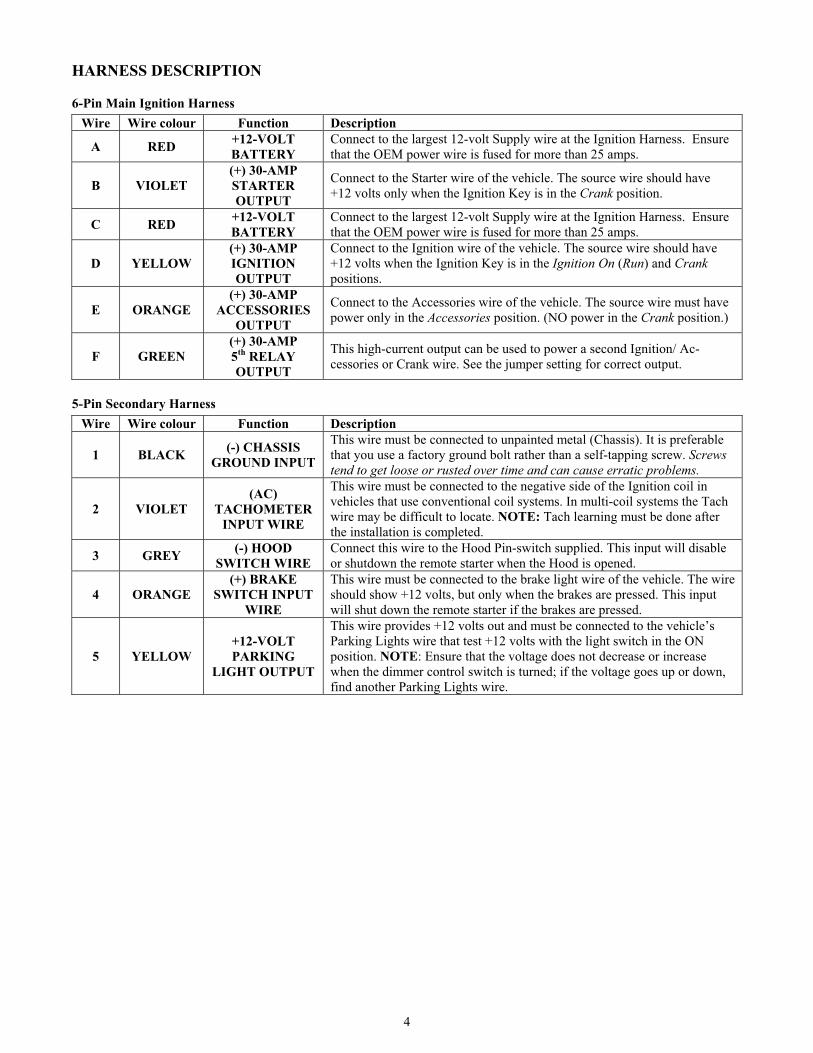
HARNESS DESCRIPTION
6-Pin Main Ignition Harness
Wire Wire colour Function Description
A RED +12-VOLT
BATTERY
Connect to the largest 12-volt Supply wire at the Ignition Harness. Ensure
that the OEM power wire is fused for more than 25 amps.
B VIOLET
(+) 30-AMP
STARTER
OUTPUT
Connect to the Starter wire of the vehicle. The source wire should have
+12 volts only when the Ignition Key is in the Crank position.
C RED +12-VOLT
BATTERY
Connect to the largest 12-volt Supply wire at the Ignition Harness. Ensure
that the OEM power wire is fused for more than 25 amps.
D YELLOW
(+) 30-AMP
IGNITION
OUTPUT
Connect to the Ignition wire of the vehicle. The source wire should have
+12 volts when the Ignition Key is in the Ignition On (Run) and Crank
positions.
E ORANGE
(+) 30-AMP
ACCESSORIES
OUTPUT
Connect to the Accessories wire of the vehicle. The source wire must have
power only in the Accessories position. (NO power in the Crank position.)
F GREEN
(+) 30-AMP
5th
RELAY
OUTPUT
This high-current output can be used to power a second Ignition/ Ac-
cessories or Crank wire. See the jumper setting for correct output.
5-Pin Secondary Harness
Wire Wire colour Function Description
1 BLACK (-) CHASSIS
GROUND INPUT
This wire must be connected to unpainted metal (Chassis). It is preferable
that you use a factory ground bolt rather than a self-tapping screw. Screws
tend to get loose or rusted over time and can cause erratic problems.
2 VIOLET
(AC)
TACHOMETER
INPUT WIRE
This wire must be connected to the negative side of the Ignition coil in
vehicles that use conventional coil systems. In multi-coil systems the Tach
wire may be difficult to locate. NOTE: Tach learning must be done after
the installation is completed.
3 GREY (-) HOOD
SWITCH WIRE
Connect this wire to the Hood Pin-switch supplied. This input will disable
or shutdown the remote starter when the Hood is opened.
4 ORANGE
(+) BRAKE
SWITCH INPUT
WIRE
This wire must be connected to the brake light wire of the vehicle. The wire
should show +12 volts, but only when the brakes are pressed. This input
will shut down the remote starter if the brakes are pressed.
5 YELLOW
+12-VOLT
PARKING
LIGHT OUTPUT
This wire provides +12 volts out and must be connected to the vehicle’s
Parking Lights wire that test +12 volts with the light switch in the ON
position. NOTE: Ensure that the voltage does not decrease or increase
when the dimmer control switch is turned; if the voltage goes up or down,
find another Parking Lights wire.

5
12-Pin Accessories Harness
Wire Wire colour Function Description
1 BLUE (-) ZONE 3
or AUX 3
500mA Negative output. This output can be used to control the Trunk
release (1-sec. pulse) or can be set to operate as a Constant as long as
TRUNK is held pressed. (For sunroof or window close.)
2 BROWN (-) LOCK Programmable 500mA, 1/10 sec, 7/10 sec – 4 sec – negative output.
3 GREEN (-) UNLOCK Programmable 500mA, 1/10 sec, 7/10 sec – 4 sec – or DBL pulse negative
output.
4WHITE /
BROWN(-) ARM
MAX 500mA ground signal when the Doors are locked by remote. This
wire will go to ground 1/4 sec. before the LOCK pulse, and go OFF 1/8 sec
after LOCK. Must be connected to the OEM Arm wire (usually the Dome
Light). NOTE: The system will also give a Rearm pulse after remote-start
shutdown on this wire.
5WHITE /
GREEN(-) DISARM
Max 500mA, 1-sec. ground pulse when the Doors are unlocked by remote.
Connect to OEM Disarm wire of the vehicle. NOTE: The system will also
give a Disarm pulse before remote start on this wire.
6
BLUE /
WHITE
(-) AUX 1
PRIORITY
DOOR ACCESS
This output will provide a 1-sec negative output (500 mA) when the
UNLOCK button on the Transmitter is pressed a second time. Can be used
as Horn Confirmation on the 2nd Lock. Can be used as Priority Door Access
when LOCK is pressed twice, or as Horn Confirmation when LOCK is
pressed or the TRUNK is released.
7
WHITE /
ORANGE
(-) STARTER
DISABLE
(ARMED
OUTPUT)
This wire will provide a constant output (500 mA) when the system is
armed (locked by remote). Can be connected to external Starter interrupt
relay.
8 ORANGE (-) AUX 2
PANIC MODE
Negative 500mA output. Can be programmed for any one of the following
three options:
(1) Constant while LOCK+UNLOCK are pressed + 1 sec after release of
buttons.
(2) LOCK + UNLOCK toggles ON / OFF. (Max.30 sec)
(3) LOCK + UNLOCK toggles ON / OFF. (Max.60 sec)
NOTE: AUX 2 can be programmed for Priority Door Unlocking.
9 VIOLET
(-) EXTERNAL
TRIGGER
INPUT
This input will start the vehicle when it receives a 1-second ground pulse
from an external pager system or timer Module. It will also shut down upon
a 1-sec. pulse when running by remote.
10 WHITE (-) GROUND-
OUTPUT
500 mA constant ground output when running.
Will become active before remote Ignition On, and shut off after the system
shuts down.
11 GRAY N/A THIS PIN IS NOT USED – LEAVE EMPTY.
12 YELLOW (+) GLOW-PLUG
INPUT
This positive input will monitor the Glow Plug light in Diesel Mode, and
will wait until the glow plug light goes out to crank the vehicle. Connect to
the positive when ON side of the glow plug light in the vehicle. NOTE:
For Diesel, the Glow Plug timing delay is 15 seconds if the Glow Plug still
ON before crank. (25 seconds if run time = 30 min.)
2-Pin Harness
Wire Wire colour Function Description
1BLUE /
WHITEN/A N/A
2 YELLOW (-) PARKING
LIGHTSNegative 500 mA Parking Lights output.
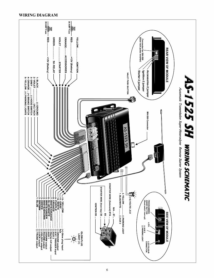
6
WIRING DIAGRAM

7
TRANSMITTER FUNCTIONS
NOTE: Pressing the LOCK and UNLOCK buttons simultaneously will activate the AUX 2 output. (The latter can be
programmed to give CONSTANT ground while pressed, or a 30- or 60-second timed output with remote toggle ON/OFF.)
LEARNING A TRANSMITTER The PS-3025 SH Transmitter does not come pre-programmed and must be code-learned after the wiring of the Module is
complete. The system has the ability to learn up to 4 different Transmitters; if a fifth Transmitter is learned, the first
Transmitter in memory will be lost. To erase all Transmitters from memory, you must perform a Module reset.
To program a new Transmitter, do the following:
1. Ensure that Ignition is OFF.
Hold the Hood Switch down for 4 seconds.
Release the Pin-switch. The Parking Lights should come on.
With Parking Lights on, immediately push and release the Pin-switch again. Parking Lights will stay on for up
to 20 seconds.
2. Turn the Ignition Key to the Ignition On (Run) position (Wait until the Parking Lights go OFF), then turn the key to
the OFF position.
(NOTE: The L.E.D. should be flashing during the next step)
3. Press the LOCK (or the UNLOCK) button until the Parking Lights flash once and come on again. Press the Lock
button again.
(NOTE: The Parking Lights will flash 5 times quickly)
4. To exit, close the Hood.
NOTE:
The L.E.D. follows the Parking Lights in all modes.
The system can hold a maximum of 4 Transmitters in memory.
THE PROGRAMMING ASSISTANCE BUTTON(A.k.a. the Hood Switch Interrupt.) Mounted on the PS-3025 SH, this Push-button can be used from within the vehicle
instead of the Hood Pin-switch: when the Hood is opened, pressing this button for 4 seconds will be equivalent to pressing
the Hood Pin-switch – it will cut the ground signal from the Hood Switch line.
NOTE: The Hood Switch must be installed and connected for the Programming Assistance Button to function.
VALET OPERATION The system can be placed in Valet Mode to disable the remote starting capabilities. This is necessary when the vehicle is
being serviced.
To get into Valet Mode:
1. Turn the Ignition Key to the Ignition On (Run) position.
2. Within 3 seconds, press and hold the Valet Switch for approx. 3 seconds. The L.E.D. will turn ON.
Remote Engine shut
down (STOP).
Cold-weather timer ON
& HOME VALET
activation.
UNLOCK (DISARM
Starter Disable) or
AUX 2 (Priority Door
Access.)
LOCK
(ARM Starter Disable)
TRUNK release or
AUX 3
Remote Engine START.

8
To get out of Valet Mode:
1. Turn the Ignition Key to the Ignition On (Run) position.
2. Within 3 seconds, press and hold the Valet Switch for 3 seconds. The L.E.D. will turn OFF.
If you try to remote-start while the vehicle is in Valet Mode, the Parking Lights will flash twice (and the Horn will chirp
twice if configured) – see the Diagnostics table at the end of this manual.
MULTI-SPEED TACH LEARNINGOn some Ignition systems, the Tach signal can be too high or too low, thus causing failed starts under certain temperatures.
The PS-3025 SH system is designed to read a wide range of Tach signals. No manual adjustments are necessary. However,
each time a new unit is installed, new Tach adjustment procedures should be carried out.
The procedures for the Tach adjustment are as follows:
1. Ensure that Ignition is OFF.
Hold the Hood Switch down for 4 seconds.
Release the Pin-switch. The Parking Lights should come on.
With Parking Lights on, immediately push and release the Pin-switch again. Parking Lights will stay on for up
to 20 seconds.
2. Press and hold the Brake Pedal and press the LOCK + UNLOCK buttons simultaneously on the Transmitter The
Parking Lights will flash 4 times.
3. Release the brake and start the vehicle and allow it to reach regular Engine idle speed. The Parking Lights will go
out when the Tach signal is detected.
4. Press and hold the Brake Pedal until the Parking Lights flash 5 times – the Tach signal has been learned.
To end TACH learning at any time, close the Hood.
If the Horn is programmed, it will honk 1, 2 or 3 times depending on which Tach Mode was detected.
PROGRAMMING OPTIONS The PS-3025 SH System is equipped with 3 custom Programming Modes, allowing the installer to custom-fit the system
according to the requirements of each vehicle.
To get into a Programming Mode you must do the following:
1. Ensure that Ignition is OFF.
Hold the Hood Switch down for 4 seconds.
Release the Pin-switch. The Parking Lights should come on.
With Parking Lights on, immediately push and release the Pin-switch again. The Parking Lights will stay on
for up to 20 seconds.
2. Press and hold the Brake Pedal, then press:
the LOCK button for Mode 1
the UNLOCK button for Mode 2
the TRUNK button for Mode 3
NOTE: Depending on the Mode you want to change, the Parking Lights will flash once for Mode 1, twice for
Mode 2, and three times for Mode 3. If Horn Confirmation is programmed, the Horn will also chirp 1, 2 or 3 times,
also indicating the Mode.
3. Release the Brake Pedal.
NOTE: The unit will stay in Programming Mode until the Hood Pin-switch is pressed or the Valet Switch is turned
off. (Therefore, take your time to make the proper selection.)
Each Mode has functions for which options must be selected. Once you have selected either Mode 1, Mode 2 or Mode 3, the
system automatically moves to function one. You must then select the desired option for each function. Once you have
selected an option, you will move to the next function, and so on.
To select one of the three options, press the appropriate button on the Transmitter (see below).
1. LOCK = option 1
2. UNLOCK = option 2
3. TRUNK = option 3
4. START = option 4
Once an option has been selected, the Parking Lights will flash 1, 2, 3 or 4 times, depending on the option that has been
selected.
Take your time to make the proper selections. The unit will stay in Programming Mode until the Hood Pin-switch is pressed.
Pressing the Brake Pedal will bring you back to the programming menu, where you can select another Mode.

9
MODE 1 *indicates default setting
FUNCTION 1 – Ignition-controlled Door Locks
OPTION 1* Ignition Locks ENABLED
OPTION 2 Ignition Locks DISABLED
OPTION 3 Ignition LOCK only
OPTION 4 Ignition UNLOCK only
FUNCTION 2 – Secure Lock
OPTION 1* Secure Lock DISABLED (1.0 Sec Disarm pulse)
OPTION 2 Smart Secure Lock ENABLED
OPTION 3 Secure Lock DISABLED (0.5 Sec Disarm pulse)
OPTION 4 Standard Secure Lock
FUNCTION 3 – Passive / Active Starter Disable Mode
OPTION 1* Starter Kill PASSIVE (1-minute timeout)
OPTION 2 Starter Disable ACTIVE
OPTION 3 Starter Disable PASSIVE (3-minute timeout)
OPTION 4 Starter Disable ACTIVE (ground output, IGN and ACC are turned on 1/4 sec. before Door Locks
– this is to shut off the Dome Light and enable Door monitoring on certain vehicles.)
FUNCTION 4 – Door Locks Timing
OPTION 1* 7/10-sec. LOCK / UNLOCK pulses
OPTION 2 4-sec. LOCK / UNLOCK pulses
OPTION 3 7/10-sec. LOCK pulse, and TWO – 1/2 sec. UNLOCK pulses
OPTION 4 1/10-sec. LOCK and 1/10-sec. UNLOCK pulses
MODE 2 *indicates default setting
FUNCTION 1 – Safe Start Mode
OPTION 1 SAFE START – ENABLED
OPTION 2* SAFE START – DISABLED
OPTION 3 SWAP START:
START button = LOCK + UNLOCK
AUX 2 = START button
FUNCTION 2 – Engine Run Time
OPTION 1 Run time = 4 minutes in Gas Mode / 9 minutes Diesel Mode
OPTION 2* Run time = 15 minutes in Gas Mode / 20 minutes Diesel Mode
OPTION 3 Run time = 25 minutes in Gas Mode / 30 minutes Diesel Mode
FUNCTION 3 – Idle Mode
OPTION 1 Idle Mode – DISABLED
OPTION 2* Idle Mode – ENABLED
FUNCTION 4 – Gas or Diesel Mode
OPTION 1 Diesel Engine Mode (Cold Weather Mode run time = 20 min.)
OPTION 2* Gasoline Engine Mode
OPTION 3 Diesel Engine Mode (Cold Weather Mode run time = 9 min.)
MODE 3 *indicates default setting
FUNCTION 1 – Home Valet Mode
OPTION 1 Home Valet – ENABLED
OPTION 2* Home Valet – DISABLED
FUNCTION 2 –AUX 3 / Zone 3
OPTION 1 Constant while TRUNK button is pressed
OPTION 2* 1-sec. Trunk 1 output when TRUNK button pressed for 3-sec while Ignition is OFF
OPTION 3 Trunk 2 output with Disarm / Rearm pulse.
OPTION 4 For FUTURE use
10
FUNCTION 3 –AUX 2
OPTION 1 Constant while pressed (LOCK & UNLOCK pressed simultaneously) or START in Safe Start Mode
OPTION 2* Toggle ON / toggle OFF with timeout up to 30 seconds
OPTION 3 Toggle ON / toggle OFF with timeout up to 60 seconds
OPTION 4 Priority Door Access
FUNCTION 4 - AUX 1
OPTION 1 Horn Confirmation on 2nd LOCK
OPTION 2* Priority Door
OPTION 3 Horn Confirmation when LOCK
FUNCTION 5 – External Trigger Sense
OPTION 1 Zone 3 (Trunk pin) rearm (controls rearm timing)
OPTION 2* Engine START / STOP
OPTION 3 Key Sense
OPTION 4 Dome Light-controlled Smart Ignition LOCK
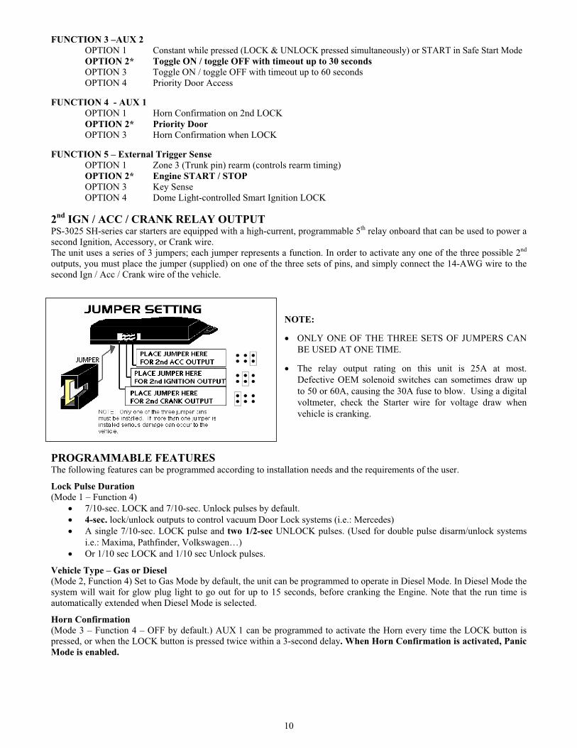
2nd
IGN / ACC / CRANK RELAY OUTPUT PS-3025 SH-series car starters are equipped with a high-current, programmable 5th relay onboard that can be used to power a
second Ignition, Accessory, or Crank wire.
The unit uses a series of 3 jumpers; each jumper represents a function. In order to activate any one of the three possible 2nd
outputs, you must place the jumper (supplied) on one of the three sets of pins, and simply connect the 14-AWG wire to the
second Ign / Acc / Crank wire of the vehicle.
NOTE:
ONLY ONE OF THE THREE SETS OF JUMPERS CAN
BE USED AT ONE TIME.
The relay output rating on this unit is 25A at most.
Defective OEM solenoid switches can sometimes draw up
to 50 or 60A, causing the 30A fuse to blow. Using a digital
voltmeter, check the Starter wire for voltage draw when
vehicle is cranking.
PROGRAMMABLE FEATURES The following features can be programmed according to installation needs and the requirements of the user.
Lock Pulse Duration
(Mode 1 – Function 4)
7/10-sec. LOCK and 7/10-sec. Unlock pulses by default.
4-sec. lock/unlock outputs to control vacuum Door Lock systems (i.e.: Mercedes)
A single 7/10-sec. LOCK pulse and two 1/2-sec UNLOCK pulses. (Used for double pulse disarm/unlock systems
i.e.: Maxima, Pathfinder, Volkswagen…)
Or 1/10 sec LOCK and 1/10 sec Unlock pulses.
Vehicle Type – Gas or Diesel
(Mode 2, Function 4) Set to Gas Mode by default, the unit can be programmed to operate in Diesel Mode. In Diesel Mode the
system will wait for glow plug light to go out for up to 15 seconds, before cranking the Engine. Note that the run time is
automatically extended when Diesel Mode is selected.
Horn Confirmation
(Mode 3 – Function 4 – OFF by default.) AUX 1 can be programmed to activate the Horn every time the LOCK button is
pressed, or when the LOCK button is pressed twice within a 3-second delay. When Horn Confirmation is activated, Panic
Mode is enabled.

11
SAFE START
(Mode 2, Function 1, OFF by default.) If this feature is enabled, it will require the user press the START button on the
remote Transmitter 2 times within 3 sec. to start the vehicle. This will eliminate accidental remote starts, for example when
there are children in the house.
If the regular Safe Start Mode is selected:
To get into Cold Weather Mode, press the START button before pressing the STOP button for 3 sec.
If the Special Safe Start Mode is selected (SWAP Mode):
To start the vehicle: press LOCK + UNLOCK buttons simultaneously.
Press START button to activate AUX2.
Idle Mode
(Mode 3, Function 3) When programmed, this option allows the user to engage the remote starter to take over the vehicle
while it is already running. This option will keep the vehicle running for the pre-programmed run time, or until it is shut
down.
To activate the Idle Mode:
While the Engine is running, press LOCK, UNLOCK or START on the Transmitter until the Parking Lights
come ON. (If Ignition Locks are disabled, the START button will not cause the Doors to be unlocked.)
Remove the key and exit the vehicle.
Lock the Doors – the vehicle will go on running for the entire pre-programmed run time.
NOTE: do not leave children or pets unattended in a vehicle running in Idle Mode!!!
Cold Weather Mode
If the Cold Weather Mode is activated, it will start and run the Engine every 2 hours for a 4-minute interval (9 or 20 minutes
for Diesel Engines) within a period of 24 hours.
To activate the Cold Weather Mode: o Press and hold the STOP button until the Parking Lights flash 3 times.
If Safe Start is on, you can activate the Cold Weather Mode by: o Pressing the START button, and then
o Pressing and holding the STOP button until the Parking Lights flash 3 times.
To check whether the system is in Cold Weather Mode: o Press and release the Brake Pedal: the Parking Lights should stay on while the Brake Pedal is pressed.
To exit the Cold Weather Mode, do any of the following: o Open the Hood.
o Start the Engine by remote.
o Turn the Ignition Key to the Ignition On (Run) position.
o Press and hold the STOP button for 3 seconds until the Parking Lights flash once.
o Turn on the Valet function (but not Home Valet).
Use Mode 2, function 4, option 1 to set a Diesel Engine to a 20-minute run time in Cold Weather Mode; otherwise set it to
9 minutes using option 3.
Ignition-Controlled Door Locks
(Mode 1, function 1, option 1 or 3.) Ignition-controlled Door Locks is enabled by default. This feature will automatically
LOCK all the Doors as soon as the key is turned to the Ignition On (Run) position and the Brake Pedal is pressed. When the
key is turned to the OFF position, the Doors will automatically be unlocked (Option 1 or 4).
Smart Ignition Locks
On the PS-3025 SH, when the Ignition-Controlled Door Locks are active and the Engine is running, whenever the Brake
Pedal is pressed while a Door that has been unlocked since the last LOCK pulse was sent, the system will relock all Doors at
once.
Engine Running Confirmation
(Mode 3, function 4, option 1 or 3.) While the Engine is already running under remote, when the START button is pressed,
the Horn will chirp if the Horn option is programmed.
Smart Rearm
On the PS-3025 SH, the system will only rearm once; extra Rearm signals will not be sent when additional Lock signals are
sent. (Certain factory alarms are affected when additional Rearm pulses are sent once the system is armed.)
Secure Lock
OFF by default. When programmed, SECURE LOCK adds an UNLOCK pulse when a START signal is received from the
Transmitter. It will provide a LOCK pulse 1 seconds after the Module starts the Engine, and a LOCK pulse 4 seconds after
it stops the Engine. When the Smart Secure Lock Mode is programmed (Mode 1, function 2, option 2), LOCK and UNLOCK
12
operations will not occur if the vehicle was disarmed. (This function is required for certain factory alarms which are triggered
by remote start operations.)
Smart Secure Lock
Some OEM factory alarm systems use the Lock wire to arm the alarm and the Unlock wire to disarm it. However most OEM
systems (with the exception of VW) will LOCK the Doors, but will not rearm the alarm while the Engine is running. With
Secure Lock, you can control certain OEM factory alarm systems without connecting other wires to disarm the alarm. If the
system is armed upon a remote START of the vehicle, it will automatically UNLOCK the Doors and disarm the OEM alarm.
Then, 1 second after the vehicle is started by remote, it will LOCK the Doors. Furthermore, 4 seconds after the Engine stops
running, Secure Lock will LOCK all the Doors and arm the system once again. If the system is disarmed there will be no
Secure Lock upon a remote START, nor will there be any Lock after the Engine stops.
Key Sense
With this option selected (Mode 3, function 5, option 3), while in Passive Mode the Starter Disable will not rearm if the key
is detected in Ignition. If Secure Lock is programmed, LOCK and Ream will not activate while the key is sensed. Connect the
External Trigger (negative input) to Key Sense on the Ignition Switch.
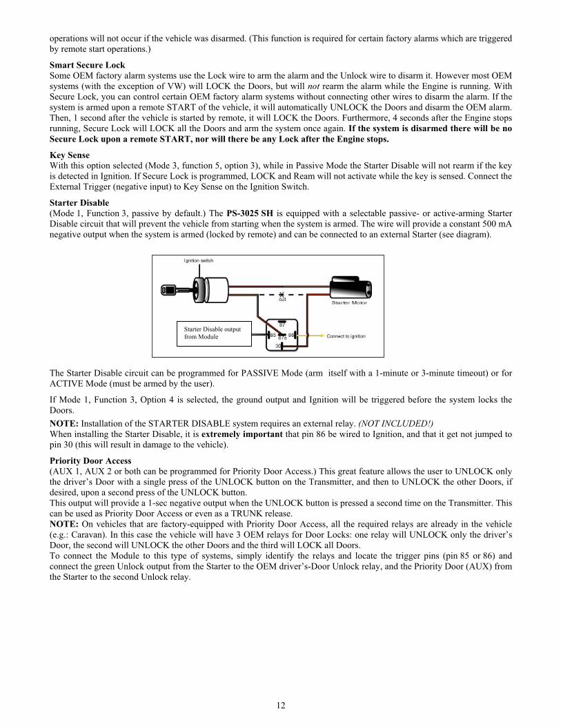
Starter Disable
(Mode 1, Function 3, passive by default.) The PS-3025 SH is equipped with a selectable passive- or active-arming Starter
Disable circuit that will prevent the vehicle from starting when the system is armed. The wire will provide a constant 500 mA
negative output when the system is armed (locked by remote) and can be connected to an external Starter (see diagram).
The Starter Disable circuit can be programmed for PASSIVE Mode (arm itself with a 1-minute or 3-minute timeout) or for
ACTIVE Mode (must be armed by the user).
If Mode 1, Function 3, Option 4 is selected, the ground output and Ignition will be triggered before the system locks the
Doors.
NOTE: Installation of the STARTER DISABLE system requires an external relay. (NOT INCLUDED!)
When installing the Starter Disable, it is extremely important that pin 86 be wired to Ignition, and that it get not jumped to
pin 30 (this will result in damage to the vehicle).
Priority Door Access
(AUX 1, AUX 2 or both can be programmed for Priority Door Access.) This great feature allows the user to UNLOCK only
the driver’s Door with a single press of the UNLOCK button on the Transmitter, and then to UNLOCK the other Doors, if
desired, upon a second press of the UNLOCK button.
This output will provide a 1-sec negative output when the UNLOCK button is pressed a second time on the Transmitter. This
can be used as Priority Door Access or even as a TRUNK release.
NOTE: On vehicles that are factory-equipped with Priority Door Access, all the required relays are already in the vehicle
(e.g.: Caravan). In this case the vehicle will have 3 OEM relays for Door Locks: one relay will UNLOCK only the driver’s
Door, the second will UNLOCK the other Doors and the third will LOCK all Doors.
To connect the Module to this type of systems, simply identify the relays and locate the trigger pins (pin 85 or 86) and
connect the green Unlock output from the Starter to the OEM driver’s-Door Unlock relay, and the Priority Door (AUX) from
the Starter to the second Unlock relay.
Starter Disable output
from Module

13
To install Priority Door Access on 2-relay OEM systems, follow the diagram below:
The OEM Unlock wire at the driver’s-Door actuator must be cut in half and a relay must be installed.
NOTE: The relay must be activated with the GREEN (-) UNLOCK output from the remote starter, and the Priority Door
(AUX) wire from the Module must be connected to the OEM negative UNLOCK wire before the Door Locks Switch in the
vehicle.
AUX 2 –Timed Output
(Mode 3, Function 3.) This 500 mA negative Auxiliary 2 output can be used for many different applications
NOTE: It can be programmed for Priority Door Access if AUX 1 is programmed for Horn confirmation.
The following diagrams show how to use this output for Headlight illumination or Remote Dome Light supervision.
Headlight Illumination
Remote-Activated Dome Light Supervision
POSITIVE TRIGGER NEGATIVE TRIGGER
14
Horn Chirp Timing
Follow these steps to program the Horn Confirmation:
1. Push the Hood Switch down, up, down and up.
2. Press the Brake Pedal.
3. Press the UNLOCK and START buttons; the Horn will chirp 5 times (Only if Horn is programmed in MODE 3 –
FUNCTION 4)
4. Release the buttons of the Remote Control; to increase the Horn Pulse by 3 ms, press the LOCK button; to decrease
the Horn Pulse by 3 ms, press the UNLOCK button; to increase the Horn Pulse by 10 ms, press the START or STOP
button; to decrease the Horn Pulse by 10 ms, press TRUNK.
For each timing change, the Horn will chirp using the new settings, except under the following circumstances:
1. When the lower limit of 5 ms is reached, the Horn will sound for 1/4 second.
2. When the upper limit of 200 ms is reached, the Horn will sound for 3/4 second.
3. A system reset will set the system back to the 22-ms default.
4. If you press LOCK and UNLOCK, 3 chirps will be heard, indicating that the new values were saved.
Or Close the Hood to cancel the changes.
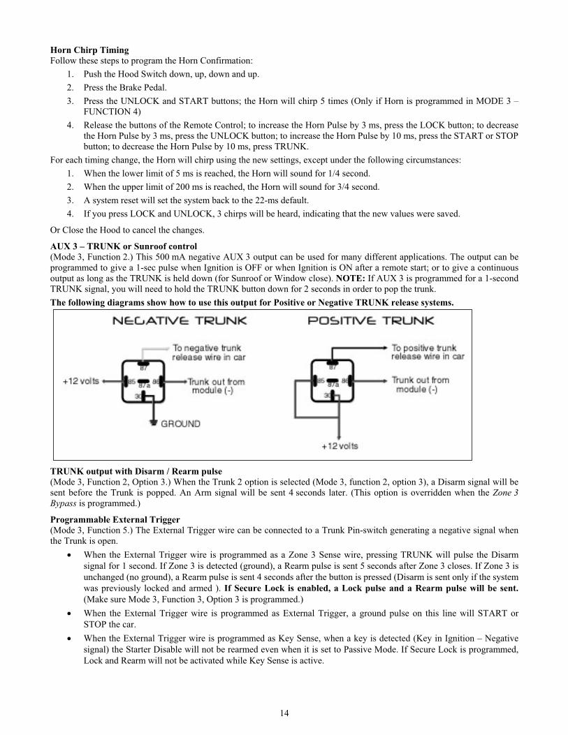
AUX 3 – TRUNK or Sunroof control
(Mode 3, Function 2.) This 500 mA negative AUX 3 output can be used for many different applications. The output can be
programmed to give a 1-sec pulse when Ignition is OFF or when Ignition is ON after a remote start; or to give a continuous
output as long as the TRUNK is held down (for Sunroof or Window close). NOTE: If AUX 3 is programmed for a 1-second
TRUNK signal, you will need to hold the TRUNK button down for 2 seconds in order to pop the trunk.
The following diagrams show how to use this output for Positive or Negative TRUNK release systems.
TRUNK output with Disarm / Rearm pulse
(Mode 3, Function 2, Option 3.) When the Trunk 2 option is selected (Mode 3, function 2, option 3), a Disarm signal will be
sent before the Trunk is popped. An Arm signal will be sent 4 seconds later. (This option is overridden when the Zone 3
Bypass is programmed.)
Programmable External Trigger
(Mode 3, Function 5.) The External Trigger wire can be connected to a Trunk Pin-switch generating a negative signal when
the Trunk is open.
When the External Trigger wire is programmed as a Zone 3 Sense wire, pressing TRUNK will pulse the Disarm
signal for 1 second. If Zone 3 is detected (ground), a Rearm pulse is sent 5 seconds after Zone 3 closes. If Zone 3 is
unchanged (no ground), a Rearm pulse is sent 4 seconds after the button is pressed (Disarm is sent only if the system
was previously locked and armed ). If Secure Lock is enabled, a Lock pulse and a Rearm pulse will be sent.
(Make sure Mode 3, Function 3, Option 3 is programmed.)
When the External Trigger wire is programmed as External Trigger, a ground pulse on this line will START or
STOP the car.
When the External Trigger wire is programmed as Key Sense, when a key is detected (Key in Ignition – Negative
signal) the Starter Disable will not be rearmed even when it is set to Passive Mode. If Secure Lock is programmed,
Lock and Rearm will not be activated while Key Sense is active.

15
When the External Trigger wire is programmed as Dome Light Monitor – Smart Ignition Lock, while the Ignition
Lock option or Lock Only option is enabled, the Doors will be re-locked every time the Door is opened and then
closed when the brake is pressed.
HOME VALET
(Mode 3 – Function 1) This amazing safety feature allows the user to remotely place the system into a no-start mode: if the
vehicle is parked indoors there is no danger it will start accidentally by Remote Control or External Trigger.
To activate Home Valet
Press the LOCK or UNLOCK button
Within 3 seconds, press the STOP button until the parking lights turn ON and remain lit for 3 sec.
To disable Home Valet, simply turn the Ignition Key to the Ignition On (Run) position.
NOTE: Once Home Valet is activated, the vehicle will not start by Remote Control or External Trigger until the Ignition Key
is turned to the Ignition On (Run) position.
GROUND OUTPUT This is a 500 mA constant ground output when the vehicle is running. It becomes active 1 second before remote Ignition ON,
and shuts OFF as soon as a system shutdown is received. It can be used to activate external relays, bypass kits or external
Modules.
PANIC MODE (in order to be available, this option must be programmed) In an emergency situation, you can activate Panic Mode. This will shut down the Engine and UNLOCK the Doors (if
UNLOCK is held pressed) or LOCK the Door (if LOCK is held), disarm the Starter Disable and sound the Horn for 30 sec.
NOTE: The Panic Mode can only be activated if the Horn is configured accordingly (Mode 3, Function 3, Option 3).
To activate the Panic Mode:
Press and hold the UNLOCK button for approximately 3 seconds until the Siren is triggered ON and the Parking
Lights flash; this will UNLOCK the Doors before the Horn is triggered.
Or press and hold the LOCK button for approximately 3 seconds until the Siren is triggered ON and the Parking
Lights flash; this will LOCK the Doors before the Horn is triggered.
The Panic Mode will automatically shut off after 30 sec.
NOTE: If you want to stop the Panic Mode before the 30-sec. delay, press the LOCK or UNLOCK button for approximately
1 second.
QUICK LOCKOUTAlso called SECURE PANIC – for quick protection: the system will LOCK all Doors when Brake Pedal is pressed when the
Horn is sounding. (This features works only when Panic Mode has been activated.)
MULTI-CAR OPERATION PS-3025 SH systems allow for Multi-Car operation. This allows the owner of two Polarstart systems, installed on two
vehicles, to control both systems with one Transmitter. (Both vehicles must be equipped with a PS-3025 SH)
The remote Transmitter of the primary vehicle can control the Starter Disable system, the Door Locks and the remote Car
Starter and TRUNK operation of the second vehicle. The remote Transmitter of the second vehicle can also operate the
primary vehicle
To program a Transmitter for a second vehicle under Multi-Car operation, you must press TRUNK + LOCK buttons
simultaneously on that Transmitter in step 3 of the Transmitter code-learning procedure.
2nd
CAR CONTROL (Press buttons simultaneously):
Press TRUNK + LOCK: LOCK
Press TRUNK + UNLOCK: UNLOCK
Press TRUNK + START: START
Press TRUNK + STOP: STOP
Press TRUNK + LOCK + UNLOCK: AUX 3 (TRUNK)

16
RESETTING THE MODULE The PS-3025 SH system is equipped with a reset function that allows the installer to erase all Transmitter codes and return all
programmed options to the factory defaults.
To reset the Module:
1. Ensure that the Valet and Ignition are both OFF.
Hold the Hood Pin-switch down for 4 sec. Release the Pin-switch.
Immediately push and release pins-witch once again.
2. Press the VALET switch 6 times or more, until the Parking Lights start to flash.
3. Parking Lights will flash 8 times.
NOTE: After a reset has been performed, the system sets all options back to default and erase all Transmitter codes. (Seeprogramming page for default option.)
EVENTS LOGGING and PLAYBACK This feature will playback the last 4 Start Failure events via the Parking Lights.
Start Failure Codes via Parking Lights:
1x = No start
3x = Hardware reset
4x = Brakes
5x = No Tach cut-off
6x = Hood
7x = Engine running, no ignition detected
8x = Already running
9x = Reserved for testing purposes
NOTE: x stands for one Parking Lights flash.
Events playback:
Hold the Hood Pin-switch down for 4 seconds and release it.
Push the Hood Pin-switch successively DOWN, UP, DOWN, UP.
The Parking Lights and the LED will flash 4 events stored in the memory
NOTE:
There is a pause after each event played back.
The system will play back the most recent event first, follows by the second most recent event, and so on.
If there is no error code for any event, the Parking Lights will give one long flash.

17
DIAGNOSTICS - PARKING LIGHTS FLASH RATE (NORMAL OPERATION)
TESTINGBefore putting back the vehicle together, it’s a good idea to check that the system operates properly. The following testing
procedures should be used to verify proper installation and operation of the system. Before testing, make sure that all
connections are soldered and that the unit is plugged in.
1. Test Hood-Switch shutdown: with the vehicle running under the Remote Starter, open the Hood; the vehicle should
shut down. If it does not shut down, check the Hood Switch and its connector.
2. Test the Brake shutdown circuit: With the vehicle running under remote, press and release the Brake Pedal. The
Engine should shut down immediately. If the Engine continues to run, check the Brake Switch connection.
3. Test all functions for proper timing and operation.
4. Remote-START the Engine and listen for Starter drag. If the Starter cranks too long, go through another TACH
learn.
CLOSING UP Use tie-wraps or screws to properly secure the starter Module and keep the wiring away from any moving parts such as the
Parking Brakes or Steering Column Shafts. Mount all switches in a good and accessible location where they do not risk
getting kicked or hit accidentally. Take the time to properly explain all functions and features to the customers before they
leave the premises. Most comebacks are the result of misunderstandings about how a product works or performs. Doing this
will save time and money. Always make all your connections before plugging in the Module, and be sure to test all functions
properly before closing up the installation.
FLASHES DESCRIPTION
1
Doors locked
End of run time
Run time cancelled
Trunk opened
Cancelled cold weather
Or cannot start after maximum attempts of tries
2 Doors unlocked.
3Entering Cold Weather Mode
Tach watch lockout.
4 +12 volts where detected on the brake line and cancelled cranking
5New Transmitter learned
Tach learnt
6 Remote start attempt was made with a Tach or a vacuum signal detected
8 Unit Reset: Occurs when the unit is reset to factory default
10 The Hood line went to ground during crank or run time
ON 2 sec. The Hood opened and the Hood switch line went to ground. This is step one of the Programming Mode.
ON 5 sec. The end stage of the procedure to program Transmitters.
ON 20 sec. If the Hood Switch is flashed twice (down-up-down-up): the unit went into step 1 of the programming
cycle.
ERRATICIf the unit flashes erratically (1 to 9 flashes followed by a pause, followed by more flashes), it is in
Playback Mode. This occurs when the Hood-Switch line is flashed 3 times (down-up-down-up-down-up).