ps_1.0.0 -tutorial (bl) - orthophoto, dem (with gcp)
TRANSCRIPT

7/22/2019 PS_1.0.0 -Tutorial (BL) - Orthophoto, DeM (With GCP)
http://slidepdf.com/reader/full/ps100-tutorial-bl-orthophoto-dem-with-gcp 1/14
First run tutorial:
Orthophoto and DEM Generation with Agisoft PhotoScan Pro 1.0.0
with Ground !ontrol Points"
PhotoScan Preferences
Open PhotoScan Preferences dialog from #ools menu using corresponding command.
Set the following values for the parameters in the General tab:
Stereo Mode: Disa$led Stereo Parallax: 1.0
Write log to file: specif% director% where Agisoft PhotoScan log would $e stored
(in case of contacting the software support team it could be required)
Set the parameters in the Open!& tab as following: !hec' on an% Open!& de(ices
detected $% PhotoScan in the dialog and reduce the nu)$er of acti(e !P* cores $% one for
each Open!& de(ice ena$led.
Set the following values for the para-
meters in the Ad(anced tab:
Project compression level: +
Keep depth maps: en$led
Store absolute image paths: disa$led
Check for updates on program star-
tup: ena$led
nable !"# support: disa$led
7/22/2019 PS_1.0.0 -Tutorial (BL) - Orthophoto, DeM (With GCP)
http://slidepdf.com/reader/full/ps100-tutorial-bl-orthophoto-dem-with-gcp 2/14
$dd PhotosTo add photos select Add Photos... command from the ,or'flow menu or click Add Photos
button located on ,or'space toolbar.
n the Add Photos dialog browse the source folder and select files to be processed. !lick Open
button.
%oad Camera Positions "t this step coordinate s#stem for the future model is set using camera positions.
&ote: f camera positions are unknown this step could be skipped. The align photos procedure$
however$ would take more time in this case.
Open Ground !ontrol pane using the corresponding command from the -iew menu.
!lick )port button on the Ground !ontrol pane toolbar and select file containing camera
positions information in the Open dialog.
The easiest wa# is to load simple character-separated file (%.t&t) that contains &- and #-
coordinates and height for each camera position (camera orientation data$ i.e. pitch$ roll and #awvalues$ could also be imported$ but the data is not obligator#).
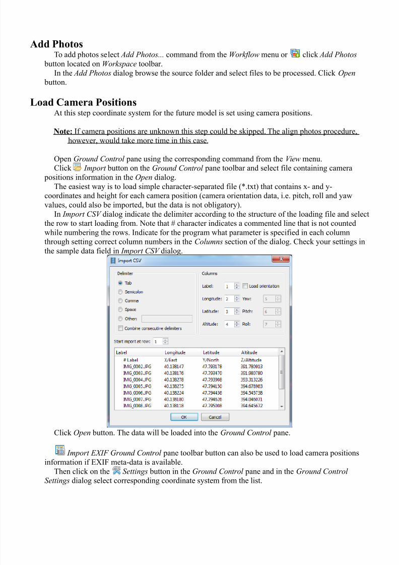
n )port !S- dialog indicate the delimiter according to the structure of the loading file and select
the row to start loading from. 'ote that character indicates a commented line that is not counted
while numbering the rows. ndicate for the program what parameter is specified in each column
through setting correct column numbers in the !olu)ns section of the dialog. !heck #our settings in
the sample data field in )port !S- dialog.
!lick Open button. The data will be loaded into the Ground !ontrol pane.
)port E/F Ground !ontrol pane toolbar button can also be used to load camera positions
information if *+ meta-data is available.
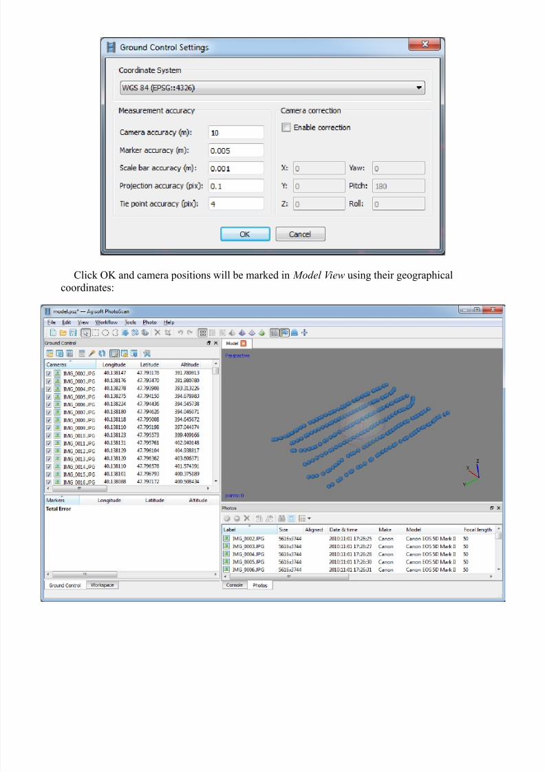
Then click on the Settings button in the Ground !ontrol pane and in the Ground !ontrol
Settings dialog select corresponding coordinate s#stem from the list.
7/22/2019 PS_1.0.0 -Tutorial (BL) - Orthophoto, DeM (With GCP)
http://slidepdf.com/reader/full/ps100-tutorial-bl-orthophoto-dem-with-gcp 3/14
!lick O, and camera positions will be marked in Model -iew using their geographical
coordinates:
7/22/2019 PS_1.0.0 -Tutorial (BL) - Orthophoto, DeM (With GCP)
http://slidepdf.com/reader/full/ps100-tutorial-bl-orthophoto-dem-with-gcp 4/14
$lign Photos"t this stage hotoScan refines the camera position for each photo and builds the point cloud
model.
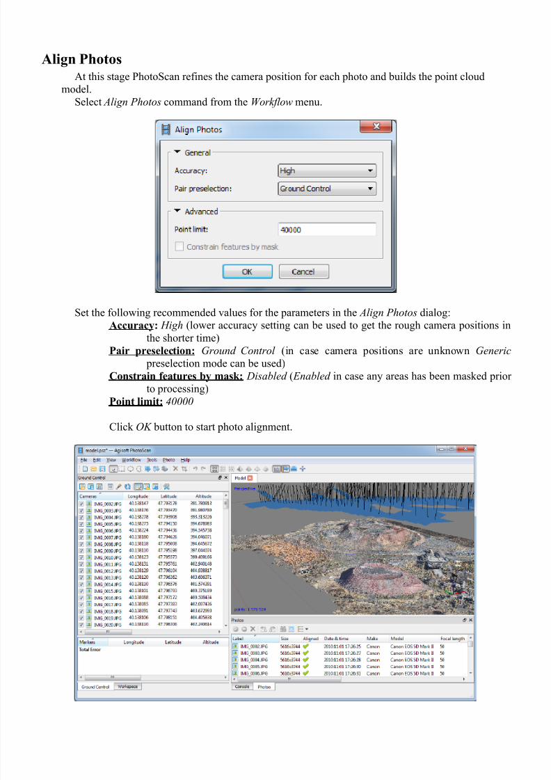
Select Align Photos command from the ,or'flow menu.
Set the following recommended values for the parameters in the Align Photos dialog:
$ccurac': igh (lower accurac# setting can be used to get the rough camera positions in
the shorter time)
Pair preselection: Ground !ontrol (in case camera positions are unknown Generic
preselection mode can be used)
Constrain features b' mask: Disa$led ( Ena$led in case an# areas has been masked prior
to processing)
Point limit: 0000
!lick O2 button to start photo alignment.

7/22/2019 PS_1.0.0 -Tutorial (BL) - Orthophoto, DeM (With GCP)
http://slidepdf.com/reader/full/ps100-tutorial-bl-orthophoto-dem-with-gcp 5/14
Place Markers arkers are used to optimi/e camera positions and orientation data$ which allows for better model
reconstruction results.
To generate accurate orthophoto at least 01 2 03 ground control points (4!) should be
distributed evenl# within the area of interest to be processed.
To be able to follow guided marker placement approach (that would be faster and easier) #ou needto reconstruct geometr# first.
Select 3uild Mesh command from the ,or'flow menu and specif# following parameters in the
3uild Mesh dialog:
!lick O, button.
Then$ when the geometr# is built (it usuall# takes a few seconds to reconstruct mesh based on thesparse point cloud)$ open a photo where a 4! is visible in hoto 5iew b# double-clicking on its
icon in the hoto pane. 6oom in to locate the 4! on the photo and place a marker in the
corresponding point of the image using !reate arker command from the photo conte&t menu
available on right-click on the opened photo in the corresponding position:

7/22/2019 PS_1.0.0 -Tutorial (BL) - Orthophoto, DeM (With GCP)
http://slidepdf.com/reader/full/ps100-tutorial-bl-orthophoto-dem-with-gcp 6/14
Select the marker on the Ground !ontrol pane. Then filter images in Photos pane using
Filter $% Mar'ers option in the conte&t menu available b# right-clicking on the markers label in the
,or'space pane.
'ow #ou need to check the marker location on ever# related photo and refine its position if
necessar# to provide ma&imum accurac#. Open each photo where the created marker is visible.
6oom in and drag the marker to the correct location while holding left mouse button. 7epeat the
described step for ever# 4!.
(nput Marker Coordinates +inall#$ import marker coordinates from a file. !lick )port button on the Ground !ontrol
pane toolbar and select file containing 4! coordinates data in the Open dialog. The easiest wa# is to
load simple character-separated file (%.t&t) that contain markers name$ &-$ #- coordinates and height.
7/22/2019 PS_1.0.0 -Tutorial (BL) - Orthophoto, DeM (With GCP)
http://slidepdf.com/reader/full/ps100-tutorial-bl-orthophoto-dem-with-gcp 7/14
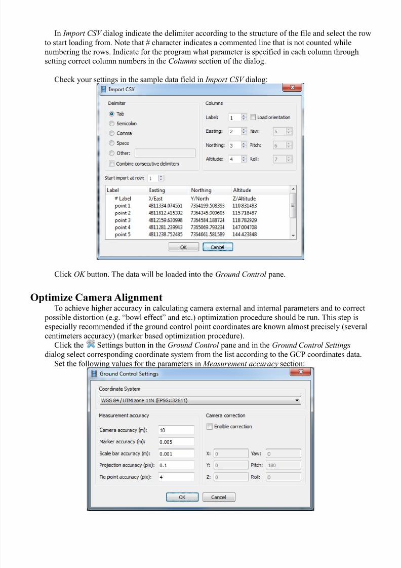
n )port !S- dialog indicate the delimiter according to the structure of the file and select the row
to start loading from. 'ote that character indicates a commented line that is not counted while
numbering the rows. ndicate for the program what parameter is specified in each column through
setting correct column numbers in the !olu)ns section of the dialog.
!heck #our settings in the sample data field in )port !S- dialog:
!lick O2 button. The data will be loaded into the Ground !ontrol pane.
#ptimi)e Camera $lignment To achieve higher accurac# in calculating camera e&ternal and internal parameters and to correct
possible distortion (e.g. 8bowl effect9 and etc.) optimi/ation procedure should be run. This step is
especiall# recommended if the ground control point coordinates are known almost precisel# (several
centimeters accurac#) (marker based optimi/ation procedure).
!lick the Settings button in the Ground !ontrol pane and in the Ground !ontrol Settings
dialog select corresponding coordinate s#stem from the list according to the 4! coordinates data.
Set the following values for the parameters in Measure)ent accurac% section:

7/22/2019 PS_1.0.0 -Tutorial (BL) - Orthophoto, DeM (With GCP)
http://slidepdf.com/reader/full/ps100-tutorial-bl-orthophoto-dem-with-gcp 8/14
Camera accurac': 01
Marker accurac': 1.113 (The marker accurac# is recommended to be set at 1 value if the
real marker accurac# is within 1.1 m. n this case hotoScan will assume
that markers coordinates are known e&actl#$ which can help to obtain more
accurate results.)
Scale bar accurac': 1.110
Projection accurac': 1.0
*ie point accurac': ;
!lick O, button.
On the Ground !ontrol pane uncheck all photos and check the markers to be used in optimi/ation
procedure. The rest of the markers that are not taken into account can serve as control points to
evaluate the optimi/ation results.
!lick Optimi/e button on the 4round !ontrol pane toolbar.
Select camera parameters #ou would like to optimi/e. !lick O, button to start optimi/ation
process.
Set "ounding "ox
<ounding bo& is resi/able and rotatable with the help of 7esi/e 7egion and 7otate
7egion tools from the Toolbar.
(mportant: The red-colored side of the bounding bo& indicates the plane that would be treated as
ground plane and has to be set under the model.
7/22/2019 PS_1.0.0 -Tutorial (BL) - Orthophoto, DeM (With GCP)
http://slidepdf.com/reader/full/ps100-tutorial-bl-orthophoto-dem-with-gcp 9/14
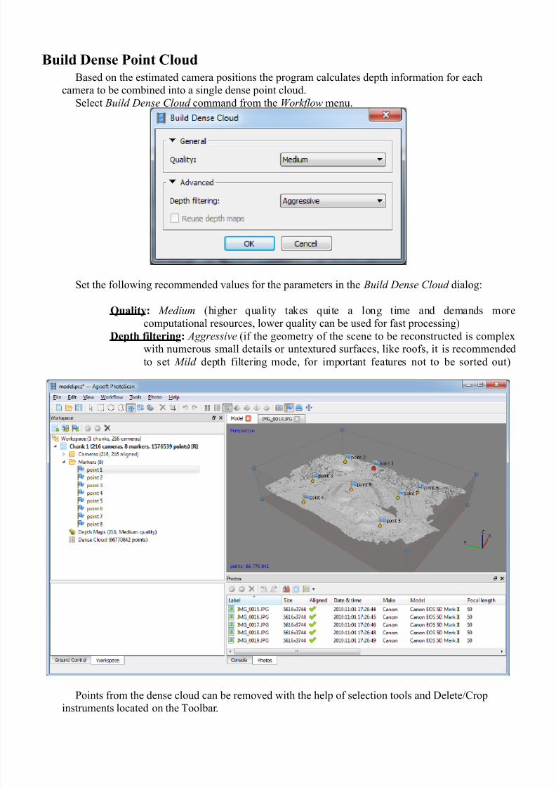
"uild +ense Point Cloud<ased on the estimated camera positions the program calculates depth information for each
camera to be combined into a single dense point cloud.
Select 3uild Dense !loud command from the ,or'flow menu.
Set the following recommended values for the parameters in the 3uild Dense !loud dialog:
,ualit': Mediu) (higher qualit# takes quite a long time and demands more
computational resources$ lower qualit# can be used for fast processing)
+epth filtering: Aggressi(e (if the geometr# of the scene to be reconstructed is comple&
with numerous small details or unte&tured surfaces$ like roofs$ it is recommended
to set Mild depth filtering mode$ for important features not to be sorted out)
oints from the dense cloud can be removed with the help of selection tools and =elete>!rop
instruments located on the Toolbar.
7/22/2019 PS_1.0.0 -Tutorial (BL) - Orthophoto, DeM (With GCP)
http://slidepdf.com/reader/full/ps100-tutorial-bl-orthophoto-dem-with-gcp 10/14
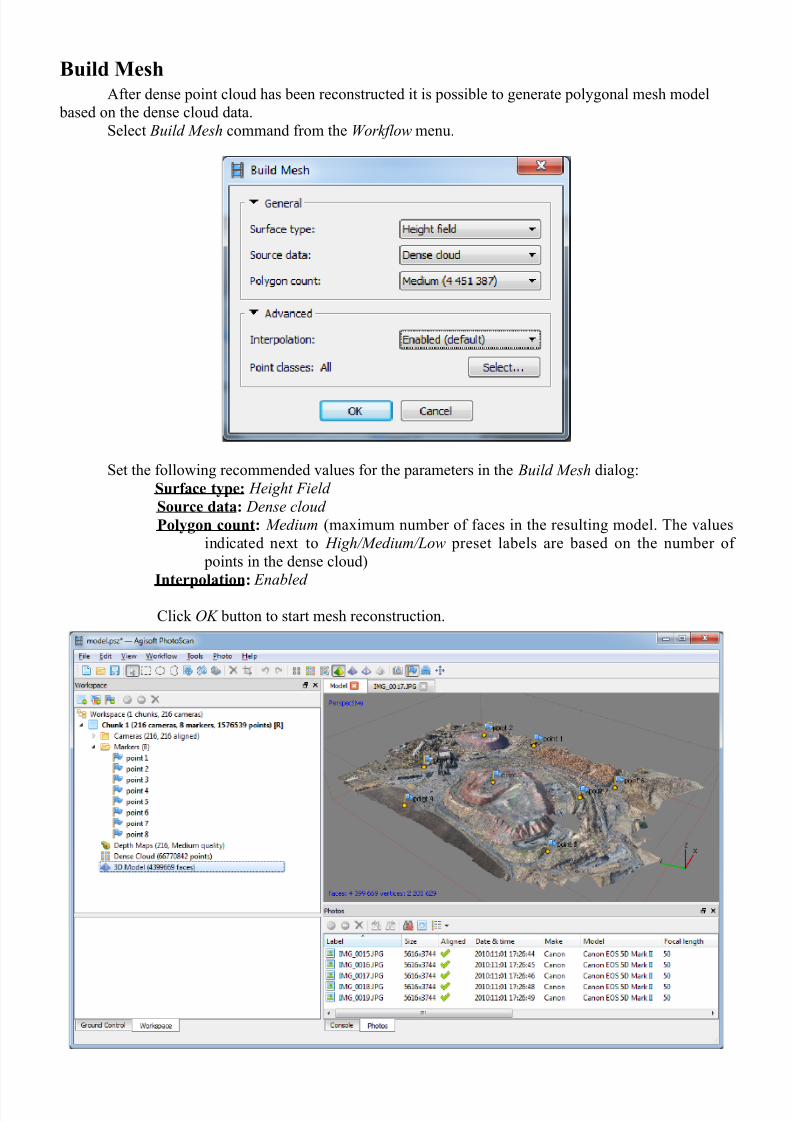
"uild Mesh"fter dense point cloud has been reconstructed it is possible to generate pol#gonal mesh model
based on the dense cloud data.
Select 3uild Mesh command from the ,or'flow menu.
Set the following recommended values for the parameters in the 3uild Mesh dialog:
Surface t'pe: eight Field
Source data: Dense cloud
Pol'gon count: Mediu) (ma&imum number of faces in the resulting model. The values
indicated ne&t to igh4Mediu)4&ow preset labels are based on the number of
points in the dense cloud)
(nterpolation: Ena$led
!lick O2 button to start mesh reconstruction.

7/22/2019 PS_1.0.0 -Tutorial (BL) - Orthophoto, DeM (With GCP)
http://slidepdf.com/reader/full/ps100-tutorial-bl-orthophoto-dem-with-gcp 11/14
dit eometr'Sometimes it is necessar# to edit geometr# before building te&ture atlas and e&porting the model.
?nwanted faces could be removed from the model. +irstl#$ #ou need to indicate the faces to be
deleted using selection tools from the toolbar. Selected areas are highlighted with red color in the
odel 5iew. Then$ to remove the selection use =elete Selection button on the Toolbar (or =@ ke#)
or use !rop Selection button on the Toolbar to remove all but selected faces.
f the overlap of the original images was not sufficient$ it ma# be required to use !lose oles
command from the #ools menu at geometr# editing stage to produced holeless model. n !lose oles
dialog select the si/e of the largest hole to be closed (in percentage of the total model si/e).
hotoScan tends to produce A= models with e&cessive geometr# resolution. ThatBs wh# it is
recommended to decimate mesh before e&porting it to a different editing tool to avoid performancedecrease of the e&ternal program.
To decimate A= model select Deci)ate Mesh... command from the Tools menu. n the Deci)ate
Mesh dialog specif# the target number of faces that should remain in the final model. +or =+ e&port
task or web-viewer upload it is recommended to downsi/e the number of faces to 011$111-11$111.
!lick O2 button to start mesh decimation procedure.
7/22/2019 PS_1.0.0 -Tutorial (BL) - Orthophoto, DeM (With GCP)
http://slidepdf.com/reader/full/ps100-tutorial-bl-orthophoto-dem-with-gcp 12/14
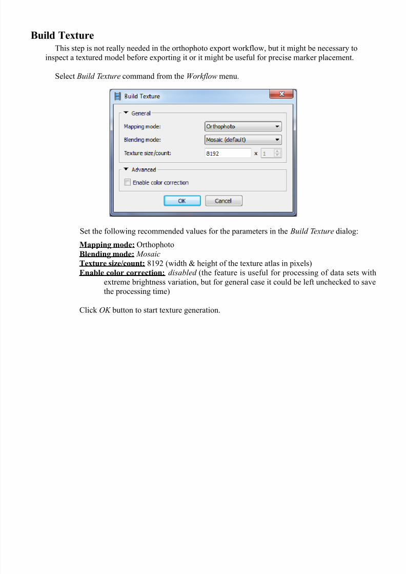
"uild *extureThis step is not reall# needed in the orthophoto e&port workflow$ but it might be necessar# to
inspect a te&tured model before e&porting it or it might be useful for precise marker placement.
Select 3uild #e5ture command from the ,or'flow menu.
Set the following recommended values for the parameters in the 3uild #e5ture dialog:
Mapping mode: Orthophoto
"lending mode: Mosaic
*exture si)e.count: C0D (width E height of the te&ture atlas in pi&els)
nable color correction: disa$led (the feature is useful for processing of data sets with
e&treme brightness variation$ but for general case it could be left unchecked to save
the processing time)
!lick O2 button to start te&ture generation.

7/22/2019 PS_1.0.0 -Tutorial (BL) - Orthophoto, DeM (With GCP)
http://slidepdf.com/reader/full/ps100-tutorial-bl-orthophoto-dem-with-gcp 13/14
enerate #rthophoto
Select E5port Orthophoto F E5port 6PEG4#FF4P7G command from File menu.
Set the following recommended values for the parameters in the E5port Orthophoto
dialog:
Projection t'pe: Geographic
Projection: b# default the proGection set in the Ground !ontrol Settings is used
"lending mode: Mosaic
nable color correction: disa$led (the feature is useful for processing of data sets withe&treme brightness variation$ but for general case it could be left unchecked to save
the processing time)
Pixel si)e: ma&imum effective resolution is shown b# default
Split in blocks: 10000 & 10000 (if the e&ported area is large it is recommended to enable
Split in 3loc's feature$ since the memor# consumption is rather high at e&porting
stage)
/egion: set the boundaries of the modelBs part that should be proGected and presented as
orthophoto.
!lick E5port... button and then specif# target file name and select t#pe of the e&ported file
(e.g. 4eoT++). !lick Sa(e button to start orthophoto generation.
7/22/2019 PS_1.0.0 -Tutorial (BL) - Orthophoto, DeM (With GCP)
http://slidepdf.com/reader/full/ps100-tutorial-bl-orthophoto-dem-with-gcp 14/14
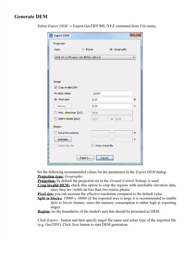
enerate +M
Select E5port DEM F &port 4eoT++><@>*H6 command from File menu.
Set the following recommended values for the parameters in the E5port DEM dialog:
Projection t'pe: Geographic
Projection: b# default the proGection set in the Ground !ontrol Settings is used
Crop invalid +M: check this option to crop the regions with unreliable elevation data$
since the# are visible on less than two source photosPixel si)e: #ou can increase the effective resolution compared to the default value
Split in blocks: 10000 & 10000 (if the e&ported area is large it is recommended to enable
Split in $loc's feature$ since the memor# consumption is rather high at e&porting
stage)
/egion: set the boundaries of the modelBs part that should be presented as =.
!lick E5port... button and then specif# target file name and select t#pe of the e&ported file
(e.g. 4eoT++). !lick Sa(e button to start = generation.