psa-t series psa1301t & psa2701t -...
TRANSCRIPT

PSA-T Series
1.3GHz & 2.7GHz RF Spectrum Analyzers
INSTRUCTION MANUAL
PSA1301T & PSA2701T
1
Table of Contents 1.Supplied Items 16
2.Using This Manual & Meaning of Terms 19
3.Initial Operations 23 3.1. Charging the Batteries 23 3.2. Initialising the Palm T|X 24 3.3. Software provided by Palm on CD 25 3.4. Linking to a Personal Computer 27
4.First Use of the Spectrum Analyzer 29 4.1. Quick Start Guide 30 4.2. Detailed Operating Guide 38
5.Product Description and Capabilities 39
6.Specification 47 6.1. Frequency Measurement 47 6.2. Amplitude Measurement 54 6.3. Sweep 62 6.4. Signal Input 64 6.5. Demodulation (Zero Span mode) 65 6.6. Display 67 6.7. Memory Storage 71 6.8. Connectors 74 6.9. Power Sources 76 6.10. Mechanical 81 6.11. Environmental and Safety 83
7.Declaration of Conformity 85
8.EMC 93
9.Safety 101
10.Connections 109 10.1. RF Signal Input 109 10.2. DC Power Input 111 10.3. Demodulated Audio Output 114 10.4. USB ‘through’ Connector 115
11.Stylus 118
12.Memory Card 120 12.1. Removing and Inserting the Card 123 12.2. Using an Alternative Card 125 12.3. Card Storage Capacity 127
13.Removing and Re-fitting the Palm T|X 129
2
14.Re-initialising the Palm T|X 134
14.1. Procedure for Re-Initialising 135 14.2. Technical Note about the OFF state 138
15.Language Choice for the Palm T|X 141
16.Turning On and Turning Off 143 16.1. Palm T|X On/Off 143 16.2. PSA1301/2701 On/Off Control 150 16.3. Operation Delay after Turning On 151
17.Battery and AC Power 152 17.1. Battery Operation 153 17.2. AC Power Operation 159 17.3. Extended Periods Without Use 161
18.Using the PSAnalyzer Application 163 18.1. Initial Conditions 163 18.2. Selecting and Leaving the Application 166 18.3. Touch Screen or Hard Key operation 168 18.4. The PSAnalyzer Screen 172 18.5. Operation and Navigation 174 18.6. Turning Off / Power Saving 176
19.The PSAnalyzer Menu System 178 19.1. Home Menu 178 19.2. Menus Summary 181 19.3. Mode Menu 186 19.4. Centre Menu 192 19.5. Step Value Sub Menu 198 19.6. Span Menu 202 19.7. Start Frequency Menu 206 19.8. Stop Frequency Menu 210 19.9. AM/FM Menu 214 19.10. Level Menu 218 19.11. Markers Menu 222 19.12. Sweep Menu 230 19.13. Traces Menu 235 19.14. Stores Menu 241 19.15. System Menu 248 19.16. Exit Menu 254 19.17. Quick Menu 258
20.PSAnalyzer Operating Techniques 267 20.1. Menu Navigation 268 20.2. Frequency Setting 271

3
20.3. Performing Sweeps 283 20.4. Level Measurements 289 20.5. The PRESET Key 293 20.6. Using Markers 295 20.7. Reference Trace 300 20.8. Store, Recall and Copy 302 20.9. Creating and Displaying Limit Lines 306 20.10. Screen Resolution and Trace Thickness 316 20.11. Changing the Palm Input Area type 318 20.12. Adjusting the Display Brightness 320
21.Help Screens 322
22.Functions outside of PSAnalyzer 325 22.1. Viewing a Stored Screen Image 325 22.2. Printing a Stored Screen Image (using a printer connected to a PC) 329 22.3. Transferring PSAnalyzer Files to a Personal Computer 331
23.PSAnalyzer Files and Defaults 338 23.1. Factory Default Settings for PSAnalyzer 338 23.2. File Locations for PSAnalyzer data files 342 23.3. File Structures for PSAnalyzer data files 344
24.Maintenance, Calibration and Repair 350 24.1. Screen Protection 350 24.2. Cleaning 353 24.3. Maintaining Battery Condition 354 24.4. Calibration 356
25.Trouble Shooting 357 25.1. Correcting Unexpected Conditions in PSAnalyzer 357 25.2. Resetting the Palm T|X 360 25.3. Reinstalling or Updating the PSAnalyzer application 365 25.4. Optional Accessories 370 25.5. Creating a Shortcut to PSAnalyzer 372
4
1. Supplied Items The PSA1301T or PSA2701T portable spectrum analyzer is made up of three main items:
The PSA1301/PSA2701 spectrum analyzer unit manufactured by TTi and incorporating a Palm T|X handheld computer. The PSAnalyzer software application created by TTi to run on the Palm T|X. An SD (or MMC) Memory Card for storing and transferring data
The following support items are also provided by TTi: “Read This First” leaflet. Universal mains adaptor/charger. USB lead (mini B plug to standard A plug). SD/MMC USB Card Reader Printed instruction manual (English only). Support CD containing multi-language manual and backup software. M2.5 security screws to prevent easy removal of the Palm T|X (if required). Transparent storage case for memory card.
The spectrum analyzer is supplied with the Palm T|X mounted into it, and the PSAnalyzer software application pre-installed. The memory card is fitted into the Palm T|X.
Note: The SD/MMC USB Card Reader and other small items may be packed inside the shipping box.
2. Using This Manual & Meaning of Terms Cross References within this Manual This manual is also provided as multi-language PDF files. The manual includes many cross references which are shown as follows - see section X.X.
Within a PDF file, the boxed number is a hyperlink to that section number, thus enabling the user to jump rapidly the section referred to and then jump back to continue reading the text.
TTi TTi is used throughout this manual as the abbreviation for Thurlby Thandar Instruments Ltd.
Handheld Computer and PDA Devices such as the Palm T|X are commonly described as handheld computers, palmtop computers or PDAs (personal digital assistants). The term ‘handheld computer’ is used throughout this manual.
PSA1301/2701 This is used to describe the spectrum analyzer unit excluding the Palm T|X handheld computer.
PSA1301/2701T This is used to describe the complete spectrum analyzer unit including the Palm T|X handheld computer.
3. Initial Operations 3.1. Charging the Batteries It is probable that the batteries will be discharged when the product is received. Consequently the first action should be to charge the unit using the supplied mains adaptor. To fully charge the batteries it should be left charging for 4 hours.
3.2. Initialising the Palm T|X If the battery has been fully discharged, the Palm T|X handheld computer will have to be re-initialised before the spectrum analyzer can be used. Details of how to re-initialise it are given in section 14.
Note: The PSA1301/2701 spectrum analyzer adaptor does not require any manual initialisation.
5
3.3. Software provided by Palm on CD The software and support information provided by Palm assumes that you will want to link your Palm T|X to a personal computer on a regular basis. The Palm “Read this First” manual instructs you to load the CD software immediately as part of the initial set up.
Users of the PSA1301/2701T do not need to do this unless they choose to. TTi recommends that users read the relevant sections of the Palm documentation and consider their own use of the product before deciding whether to install to Palm software.
Note: Do NOT make a USB connection between the PSA1301/2701T (or the Palm T|X) and a PC unless the Palm software has already been installed.
3.4. Linking to a Personal Computer The following applies to both the PSA-T and the Palm T|X by itself. (The mini USB connection on the side of the spectrum analyzer is a direct through connection to the USB port of the Palm T|X).
Although the Palm T|X was designed to be USB connected to a PC using Palm Desktop software, this software is now obsolete and will not work with 64-bit operating systems.
It is NOT necessary ever to link the PSA1301/2701T to a personal computer. It is a self contained instrument which can perform its primary function of RF spectrum analysis without linkage to other devices. TTi provides a USB linked memory card reader in order that PSAnalyzer files can be transferred to a PC where this is required.
4. First Use of the Spectrum Analyzer After charging the battery and initialising the Palm T|X, it will then be possible to use the Spectrum Analyzer by launching the PSAnalyzer application.
TTi recommends that you should read this manual in full before using the PSA1301/2701T.
However, if immediate use of the spectrum analyzer is required, the following procedure can be used to start making measurements quickly.
4.1. Quick Start Guide Before commencing - the batteries must have been charged and the Palm T|X initialised as described in sections 3.1 and 14 respectively.
1. Connect the signal to be measured - connect signal to the SMA connector at the top of the spectrum analyzer. The maximum allowable signal without damage is +20dBm (+127dBuV or 2.2 V rms). The maximum measurable signal is 0dBm (+ 107dBuV or 223 mV rms). If there is a possibility of the signal exceeding these levels, add suitable in-line attenuation.
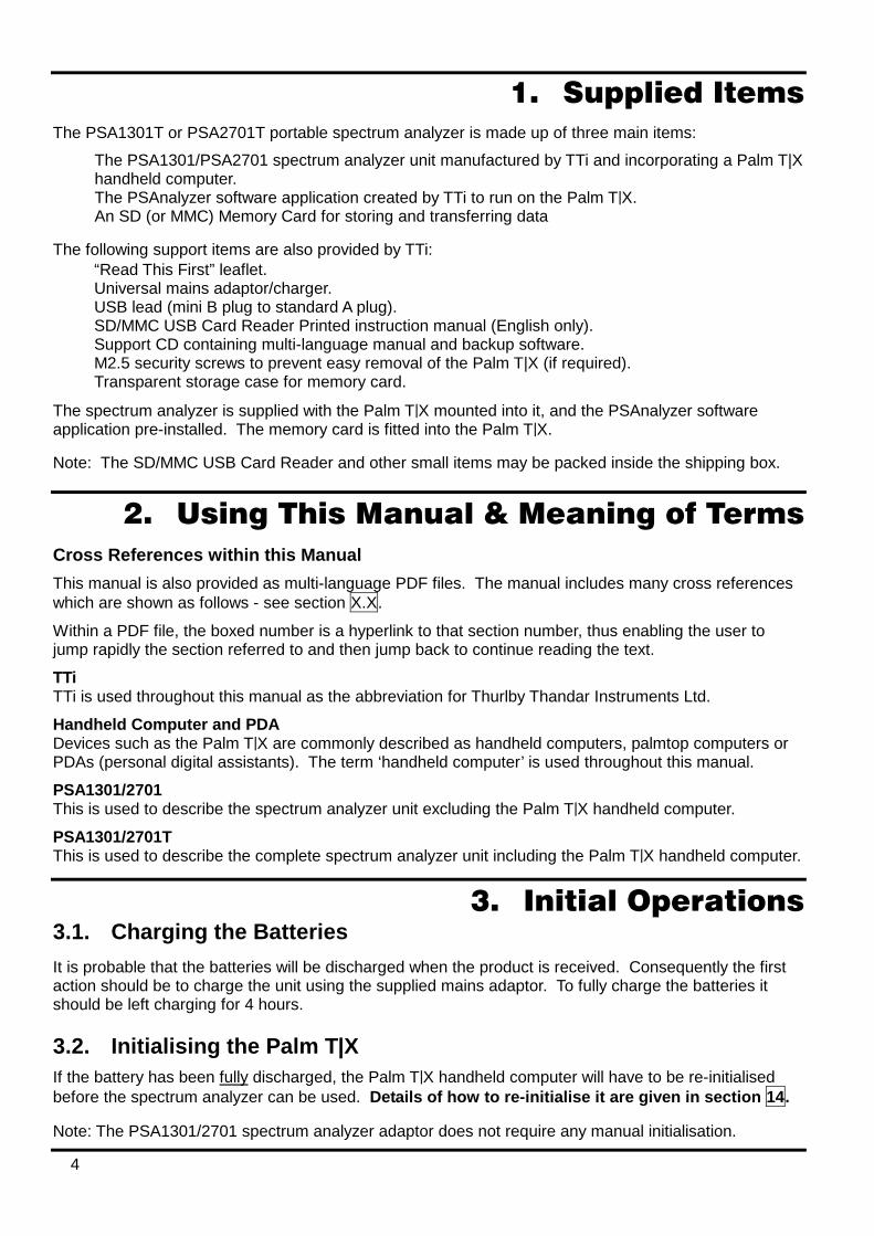
2. Launch the PSAnalyzer application - enter the Applications screen (by pressing the Home key once or twice). Press the PSAnalyzer icon on the touch screen of the Palm T|X, (the touch screen can be operated with a fingertip or the stylus of the Palm T|X).
3. Select the Mode Menu - press the on-screen Mode key.
6
4. Select Preset – press the Preset key. This sets Quick Menu mode, Span maximum, Attenuation on, Highest RBW, Sweep mode normal, Marker M1 on at the centre of the sweep.
5. Observe the Sweep - the sweep time will be slow because of the wide span.
6. Adjust the Attenuator – If the peak signal is below the –20dBm graticule line, press the Attenuator On/Off key to toggle the attenuator to Off thus increasing the sensitivity.
7. Move the Marker – use the 5-way navigator to move the marker to the area of interest and position it at the centre of the signals to be observed.
8. Centre the Sweep -.press the Set C=M1 key to re-centre the sweep around the new marker position
(Note: the span will be reduced to the maximum that can be achieved with the new centre frequency)
9. Zoom the Span – Press the Zoom-In key successively to create a narrower span that shows more
detail of the signals of interest.
The above procedure should be sufficient to get started. Thereafter adjustments can be made to sweep parameters, attenuator, resolution bandwidth, etc. as may be appropriate to the signals being observed.
Basic on-screen help information for every menu is available by pressing the Help hard key. Some general information regarding the capabilities of the unit is available from the Info key on the Exit menu.
4.2. Detailed Operating Guide To fully understand the operation of the PSA1301/2701T and PSAnalyzer, it is necessary to read this manual.
From an operating point of view, the key sections are “Using the PSAnalyzer Application” section18, “The PSAnalyzer Menu System” section 19, and “PSAnalyzer Operating Techniques” section 20.
5. Product Description and Capabilities Brief Summary The PSA-T series (PSA1301T and PSA2701T) are fully portable spectrum analyzers incorporating a handheld computer (a Palm T|X). They are sufficiently small and lightweight to be operated as a handheld instrument and has a typical battery life of four hours from each charge. Alternatively they can be used as bench instruments using the supplied mains adaptor/charger. They can be set horizontally or vertically, or at an angle of about 25 degrees using the built-in tilt stand.
The spectrum analyzer has a frequency range of 0.15 MHz to 1300 MHz (PSA1301T) or 1MHz to 2700MHz (PSA2701T). The span can be set anywhere between 0.320 MHz and 1299.850 MHz (PSA1301T) or 2699.000 MHz (PSA2701T) with a resolution of 1kHz. Start, stop or centre frequencies can be set to the same resolution. The resolution bandwidth is selectable as 280 kHz or 15 kHz (PSA1301T) or 1 MHz, 280 kHz or 15 kHz (PSA2701T).

7
The on-screen amplitude range is 80 dB with a reference level of -20dBm or 0dBm. Amplitudes can alternatively be displayed in dBµV. Vertical magnification to 5dB/div can be selected. Average noise floor is better than -90dBm at -20dBm reference level and 15 kHz RBW.
Sweeps can be continuous, single shot, peak hold or average (2 to 256 sweeps). Sweep time is defined by the span and resolution bandwidth, and varies between 0.1 sec and 30 sec. A zero span mode is available with AM or FM audio demodulation.
Twin vertical marker lines are available giving a readout of frequency and amplitude to a resolution of 0.1 kHz and 0.1 dB. Markers can be manually positioned or automatically peak finding and tracking.
A reference trace can be displayed in addition to the live trace. Limit lines can also be created and displayed.
The graticule is fully controllable. Any number of traces can be stored to permanent memory for recall to the screen or for data export. Limit lines, instrument set-ups and complete screen bitmaps can also be stored.
Battery life depends upon screen brightness, but is around four hours of continuous operation from a charge. To conserve the battery, auto-sleep mode can be selected whereby the unit turns off automatically after a defined period from the last key press. All data is retained when off.
Pressing the Help hard key brings up a help screen relevant to the current menu position.
Full details of the product capabilities are given with the Specification section 6 and Using the PSAnalyzer Application section 18 onwards.
8
6. Specification
6.1. Frequency Measurement Frequency Span
Frequency Range: 150 kHz to 1300 MHz in one range (PSA1301) 1 MHz to 2700 MHz in one range (PSA2701)
Setting Modes: Centre frequency plus Span, or Start frequency plus Stop frequency
Maximum Span: 1299.85 MHz [150 kHz to 1300 MHz] (PSA1301) 2699 MHz [1 MHz to 2700 MHz] (PSA2701)
Minimum Span: 320 kHz, or Zero Span with demodulation
Setting Resolution: 1 kHz at any frequency
Setting Accuracy: Reference Frequency Accuracy for Start, Stop & Centre (Zero-Span) frequencies
Reference Frequency Accuracy
Initial Accuracy: Better than ± 10 ppm at 20oC
Stability: Better than ± 10 ppm over 10oC to 30oC
Ageing: Better than ± 3 ppm per year
Phase Noise
Phase Noise: Typically -100dBc/Hz at 100kHz offset at 500MHz (PSA1301) Typically -90dBc/Hz at 100kHz offset at 500MHz (PSA2701)
Resolution Bandwidth
RBW: Selectable as 280 kHz or 15 kHz (PSA1301) Selectable as 1 MHz, 280 kHz or 15 kHz (PSA2701)
Video Filtering: Selectable independently of RBW setting
Frequency Markers
Number of Markers: One, Two, or None
Marker Resolution: 0.1 kHz at all frequencies
Marker Accuracy: 1/320th of Frequency Span ± 0.1kHz + Reference Frequency Accuracy
Frequency Readout: Display of absolute and difference frequencies for both markers
6.2. Amplitude Measurement Amplitude Range Display Range: 80 dB
Measurement Units: dBm or dBµV (dB milliwatts or dB micro volts)
Reference Level: Selectable as -20 dBm or 0dBm (87 dBµV or 107 dBµV)
9
Amplitude Accuracy
Ref. Level Accuracy: Better than ± 1 dB at 50MHz at 10dB below reference level (20oC ± 5oC)
Level Flatness: Better than ± 1.5 dB relative to 50MHz over 500kHz to 1300MHz (PSA1301) Better than ± 1.5 dB relative to 50MHz over 1MHz to 2700MHz (PSA2701)
Amplitude Linearity: Better than ± 1 dB over 50dB range down from reference level
Noise Floor
Noise Floor: Better than -93 dBm average displayed noise floor (PSA1301) (reference level = –20 dBm, RBW = 15 kHz) Better than -93 dBm average displayed noise floor for F > 3MHz (PSA2701) (reference level = –20 dBm, RBW = 15 kHz)
Distortion and Spurii
3rd Order Intermod.: < –60dBc for two signals (500MHz and 501MHz) at 10dB below reference level (PSA1301) < –60dBc for two signals (500MHz and 502MHz) at 10dB below reference level (PSA2701)
Harmonic: < –60dBc at 10dB below reference level (100MHz)
1st & 2nd Image: <– 55dBc, typically <– 60dBc
Residual Spurii: Below noise floor (PSA1301) <3dB above noise floor (PSA2701)
Amplitude Markers
Number of Markers: One, Two, or None
Marker Resolution: 0.1 dB
Amplitude Readout: Display of absolute and difference amplitudes for both markers
Limit Lines
Limit lines are created from lists of amplitude & frequency points. Straight lines are drawn between these points.
Displayed Lines: One, two (or none) differentiated by colour.
Line Storage Any number of limit lines can be stored.
6.3. Sweep Sweep Method: Peak detection for 320 points per sweep. The amplitude of the peak level found
within each sub-span is stored (sub-span = span/320).
Sweep Time: Set automatically by Span and RBW. Typically 200ms + 2ms/MHz of span for RBW = 1MHz (PSA2701 only) Typically 200ms + 7ms/MHz of span for RBW = 280kHz Typically 200ms + 75ms/MHz of span for RBW = 15kHz
Sweep Modes: Normal (continuous), Single, Peak Hold, or Average (2 to 256 sweeps)
Sweep Control: Separate buttons for Run and Stop. Peak Hold and Average are reset whenever Run is pressed.

10
6.4. Signal Input Input Connector: SMA connector, 50 Ohms
VSWR: 1.5:1 typical
Absolute Maximum Input Level:
+ 20 dBm or +127 dBµV (2.2V rms) or 15V dc
6.5. Demodulation (Zero Span mode) Demod. Modes: AM or FM
Display: Carrier amplitude only (horizontal line).
Audio Out: 30 mW into 32 Ohms mono or stereo headphones, adjustable volume, 3.5mm jack socket ( marked ) adjacent to the Signal Input.
Audio Filter Selectable low-pass filter to attenuate high frequency interference. 2 pole filter with turnover point at approximately 3 kHz.
6.6. Display Display Type: 3.7 inch (9.4 cm) transflective backlit TFT LCD, 480 x 320 pixels total, 16 bit
colour, touch screen.
Trace Area: 300 x 320 pixels (high resolution mode).
Graticule: 8 x 10 divisions light grey graticule. Selectable as fully on, horizontal lines only, or off).
Displayed Points: 320 points per sweep (peak detected).
Live Trace: Dot-joined trace from current or held sweep. Selectable on or off.
Reference Trace: Stored trace either recalled from memory or copied directly from live trace. Selectable on or off.
Resolution Modes: Selectable as High Resolution or Low Resolution *
∗ In low resolution mode the trace area becomes 150 x 160 points where each point is a block of 4 pixels. Only 160 sweep points are displayed. This mode is useful in situations where the display could otherwise be difficult to see - e.g. when the instrument cannot be viewed at an optimum distance.
6.7. Memory Storage Memory Type: Non volatile Flash memory using removable SD or MMC memory cards.
Store Trace: Any number of traces can be stored under either default file names or user entered file names. Traces are stored as tables of amplitude versus frequency and can be imported into other programs, as well as being recalled to the screen.
Recall Trace: Recalls any stored trace to the reference trace of the display.
Store Set-up: Any number of instrument set-ups can be stored under either default file names or user entered file names. All settings of the instrument are saved.
Recall Set-up: Recalls any stored set-up, overwriting the existing settings of the instrument.
11
Store Screen: This function copies the whole screen area to memory as a bit-map. Any number of screens can be stored under either default file names or user entered file names. Screen bit-maps can be viewed using the “Media” application of the Palm T|X, or transferred to a PC for printing.
Store/Recall Limit Lines
Any number of limit lines can be stored under either default file names or user entered file names, and recalled as required.
6.8. Connectors RF Input Connector: Standard SMA connector.
Power Connector: 1.3 mm dc power socket (centre positive) for 5.2V/1A external AC power adaptor/charger as supplied by TTi.
USB Connector: Mini USB connector (5 pin mini B) which provides direct access to the USB port of the Palm T|X.
Audio Connector: 3.5 mm jack socket for demodulated audio out (accepts mono or stereo plugs).
6.9. Power Sources AC Line Operation/Charging The PSA1301/2701T can be operated from mains power using the AC power adaptor provided by TTi. This powers and recharges both the Spectrum Analyzer and the Palm T|X simultaneously.
AC Adaptor/Charger
Input Voltage Range: 100V to 240V nominal 50Hz/60Hz. Interchangeable plus for UK, Euro, USA and Australia are supplied.
Battery Operation The PSA1301/2701 and the Palm T|X contain their own internal rechargeable battery packs. The PSA1301/2701 is turned off automatically whenever the PSAnalyzer program is exited, or when the Palm T|X is turned off.
PSA1301/2701 Spectrum Analyzer
Battery Type: Ni-Mh 3.6V 700mA-hr (3 x AAA cell)
Battery Life: > 5 hours continuous operation (PSA1301) > 4 hours continuous operation (PSA2701)
Recharge Time: < 3 hours from fully discharged
Palm T|X
Battery Type: Li-ion 3V 1050mA-hr
Battery Life: Typically 4 hours continuous operation (depending on backlight brightness)
Recharge Time: < 4 hours from fully discharged
Auto Sleep Mode To conserve battery life, the system can be set to automatically switch into sleep mode after a defined time from the last key press. This can be set between 5 mins and 60 mins (or never).
12
6.10. Mechanical Size: 170mm high x 97mm wide x 47mm deep (including feet)
Weight: 495 grms total including Palm T|X.
Tilt Stand: Built-in tilt stand for bench use which angles the unit at approximately 25 degrees to the horizontal and can alternatively be used as a hook mount.
6.11. Environmental and Safety Operating Range: +5oC to + 40oC, 20% to 80% RH.
Storage Range: -10oC to +50oC
Environmental: Indoor use at altitudes to 2000m, Pollution Degree 2.
Electrical Safety: Complies with EN61010-1.
EMC: Complies with EN61326.

13
7. Declaration of Conformity
EC Declaration of Conformity
We Thurlby Thandar Instruments Ltd Glebe Road Huntingdon Cambridgeshire PE29 7DR England
declare that the
PSA1301T and PSA2701T Portable RF Spectrum Analyzers
meet the intent of the EMC Directive 2004/108/EC and the Low Voltage Directive 2006/95/EC. Compliance was demonstrated by conformance to the following specifications which have been listed in the Official Journal of the European Communities.
EMC Emissions: a) EN61326 (2006) Radiated, Class B
Immunity: EN61326 (2006) Immunity Table 1, referring to:
a) EN61000-4-2 (2009) Electrostatic Discharge
b) EN61000-4-3 (2006) Electromagnetic Field
c) EN61000-4-4 (2004) Fast Transient
Performance levels achieved are detailed in the user manual.
Safety
EN61010-1 Pollution Degree 2.
CHRIS WILDING TECHNICAL DIRECTOR 2 January 2013
14
8. EMC Spectrum Analyzer
This instrument has been designed to meet the requirements of the EMC Directive 2004/108/EC. Compliance was demonstrated by meeting the test limits of the following standards:
Emissions EN61326 (2006) EMC product standard for Electrical Equipment for Measurement, Control and Laboratory Use. Test limits used were: a) Radiated: Class B
Immunity EN61326 (2006) EMC product standard for Electrical Equipment for Measurement, Control and Laboratory Use.
Test methods, limits and performance achieved are shown below (requirement shown in brackets):
a) EN61000-4-2 (2009) Electrostatic Discharge : 4kV air, 4kV contact, Performance A (B).
b) EN61000-4-3 (2006) Electromagnetic Field: 3V/m, 80% AM at 1kHz, 80MHz – 1GHz: Performance B (A) and 1.4GHz to 2GHz: Performance B (A); 1V/m, 2.0GHz to 2.7GHz: Performance B (A).
Note: The PSA-T Series spectrum analyzers are extremely sensitive instruments and, as a result, show some susceptibility to high electromagnetic fields throughout their measurement range. In general, the instrument will operate correctly but may show the interfering frequencies on the measurement trace if the levels are very high.
c) EN61000-4-4 (2004) Fast Transient, 0.5kV peak (signal input), Performance B (B).
Performance Definitions The definitions of performance criteria are: Performance criterion A: ‘During test normal performance within the specification limits.’ Performance criterion B: ‘During test, temporary degradation, or loss of function or performance which is self-recovering’.
Adaptor/Charger This AC adaptor/charger has been designed to meet the requirements of the EMC Directive 2004/108/EC.
Compliance was demonstrated by meeting the test limits of the following standards:
Emissions
EN55022, radiated and conducted Class B.
Immunity EN55024:1998/A1:2001/A2:2003, referring to:
a) IEC 61000-4-2 (2009) Electrostatic Discharge.
b) IEC 61000-4-3 (2006) Electromagnetic Field.
c) IEC 61000-4-11 (2004) Voltage Interrupt.
d) IEC 61000-4-4 (2004) Fast Transient.
e) IEC 61000-4-5 (2006) Surge.
f) IEC 61000-4-6 (2009) Conducted RF.

15
9. Safety Spectrum Analyzer This instrument is Safety Class III according to IEC classification and has been designed to meet the requirements of EN61010-1 (Safety Requirements for Electrical Equipment for Measurement, Control and Laboratory Use).
This instrument has been tested in accordance with EN61010-1 and has been supplied in a safe condition. This instruction manual contains some information and warnings which have to be followed by the user to ensure safe operation and to retain the instrument in a safe condition.
This instrument has been designed for indoor use in a Pollution Degree 2 environment in the temperature range 5°C to 40°C, 20% - 80% RH (non-condensing). It may occasionally be subjected to temperatures between +5° and -10°C without degradation of its safety. Do not operate while condensation is present.
Use of this instrument in a manner not specified by these instructions may impair the safety protection provided.
WARNING! All accessible parts will be at the same voltage as the outer body of the SMA input socket. In particular, note that the shell of the mini-USB connector is galvanically connected to the body of the SMA input which will therefore be at earth ground potential when the USB port is connected to a desktop PC. To maintain user safety under all other circumstances it is essential that the input is not connected to a voltage above 30Vdc or 30Vrms with respect to earth ground which is the limit of Safe Extra Low Voltage (SELV) by IEC definition.
The instrument shall be disconnected from all voltage sources before it is opened for any adjustment, replacement, maintenance or repair.
Any adjustment, maintenance and repair of the opened instrument under voltage shall be avoided as far as possible and, if inevitable, shall be carried out only by a skilled person who is aware of the hazard involved.
Do not wet the instrument when cleaning it.
The following symbols are used on the instrument and in this manual.
Direct Current
CAUTION – refer to accompanying documentation. Damage to the instrument may occur if these precautions are ignored.
Adaptor/Charger The adaptor/charger supplied has a universal input voltage rating of 100-240VAC, 50/60Hz. It is a Class II (double insulated) device, fully approved to EN 60950-1 (2001), UL 60950 (UL listing E138754) and AS/NZS CISPR:2002 (C-Tick).
16
10. Connections
10.1. RF Signal Input The signal to be measured is connected via a standard (non reverse) SMA connector mounted at the top of the instrument. The input impedance is 50 Ohms. The maximum allowable input is +20dBm or +127dBuV of RF power (approximately 2.2 volts RMS), or 15V DC.
Applying a signal above these levels could damage the unit and such damage would not be covered by the product warranty.
It should be noted that SMA connectors have a limited mechanical life and that, where frequent connection and disconnection is expected, a sacrificial intermediate connector should be used.
10.2. DC Power Input DC power to operate and/or recharge the instrument is connected via a 1.3mm power socket mounted on the side of the instrument.
Use ONLY the mains adaptor provided by TTi with the unit. Use of any other power source will void the warranty.
The batteries of the spectrum analyzer unit and of the Palm T|X are automatically charged whenever dc power is connected.
An LED adjacent to the socket shows that the batteries of the PSA1301/2701 are recharging. When they are fully charged this LED will go off. The charging state and charge level of the Palm T|X batteries is shown on the display of the T|X, see section 17.1
10.3. Demodulated Audio Output
Demodulated audio (when in Zero Span Mode) is provided via a 3.5mm stereo jack socket ( marked ) mounted at the top of the instrument adjacent to the RF Signal Input. Maximum power output is 32 milliwatts into 32 Ohms with the volume level adjustable from within the application.
The signal is mono but connection can be made using either a mono or stereo plug. In the latter case the signal will be present on both channels.
10.4. USB ‘through’ Connector The USB port of the Palm T|X can be accessed via a mini USB connector (mini type B) mounted on the side of the instrument. A cable is provided to connect this to a standard computer USB port.
Note that the USB interface has no function within the PSAnalyzer application, the cable is supplied in order that Palm Desktop software can be used with the Palm T|X in situ within the PSA1301/2701T.
Note: The USB cable should be disconnected at the PSA1301/2701T end when using the PSAnalyzer application.
Important - Do NOT try to make a USB connection to a PC which has not had the appropriate software loaded onto it.
17
11. Stylus Handheld computers such as the Palm T|X are normally operated using the supplied stylus. The PSAnalyzer application has been written so that use of a stylus is not a requirement, see section 18.2 . Nevertheless some users may prefer to operate it using a stylus.
The stylus provided with the Palm T|X clips into a slot on its right hand edge. When the T|X is fitted into the PSA1301/2701, the stylus fits into the same slot but is prevented from sliding as far down as normal by a stop incorporated within the top cover. This ensures that the stylus remains easily accessible.
Note: If access to the stylus is not required, it can be pushed past the stop. If this is done, however, it will not be possible to access it without removing the Palm T|X from the PSA1301/2701T.
12. Memory Card The PSA1301/2701T is supplied complete with a Flash memory card (type SD or MMC). This card is necessary for storing and recalling traces, screens and set-ups in PSAnalyzer. A backup of the original PSAnalyzer program is also stored on the card.
The memory card can be used in many other Palm applications, both as additional memory and as a convenient way of sharing data with other devices. Note: Palm documentation refers to a memory card as an expansion card.
PSAnalyzer can be used without any card in place, but storing or recall of traces, screens or set-ups will not be available.
The memory card can be used as a means of transferring data to and from a PC using the USB card reader supplied. See section 22.3 for details.
12.1. Removing and Inserting the Card The card fits into a slot on the top left hand edge of the Palm T|X and is slightly recessed relative to the top edge of the PSA1301/2701.
To remove the card, press it down and then release it (a confirmation tone may be heard). The card becomes free and can be slid out. To insert the card, slide it into the slot and press it down firmly until a click is felt and the confirmation tone is heard.
Note: When a card is inserted, the Applications screen is automatically switched to show the applications which are on the card. In the case of the card supplied with the PSA1301/2701T this will be the utility PSAInstaller. To return to the normal Applications screen, select the drop down menu at the top right and select “All” in place of “Card”.
12.2. Using an Alternative Card Any SD (secure digital) or MMC (multi media) card that is compatible with the Palm T|X can be used in place of the one supplied. When PSAnalyzer stores a file it automatically creates the required folder structure. Multiple cards could be used increase total capacity or to separate files related to different projects. Note that the maximum card size useable with the Palm T|X is 2GB.
Note: The original card should be retained as it contains an important utility and a backup of the PSAnalyzer application. This card is labelled with the TTi logo and with the version number of the supplied PSAnalyzer software.
18
12.3. Card Storage Capacity The size of the memory card supplied by TTi may vary from time to time, but will be in the range 512MB to 2GB.
The size if the files stored by PSAnalyzer are very small in comparison. Set-up files are a few hundred bytes each, trace files are around six kilobytes each, and screen bitmap files are 120 kilobytes each. Note, however, that the FAT16 format of the card creates a minimum file allocation size of 16 kilobytes (or possibly greater) for any file stored.
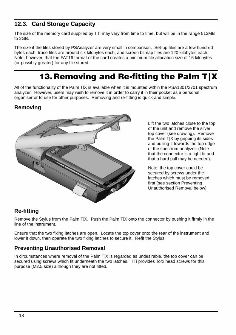
13. Removing and Re-fitting the Palm T|X All of the functionality of the Palm T|X is available when it is mounted within the PSA1301/2701 spectrum analyzer. However, users may wish to remove it in order to carry it in their pocket as a personal organiser or to use for other purposes. Removing and re-fitting is quick and simple.
Removing
Re-fitting Remove the Stylus from the Palm T|X. Push the Palm T|X onto the connector by pushing it firmly in the line of the instrument.
Ensure that the two fixing latches are open. Locate the top cover onto the rear of the instrument and lower it down, then operate the two fixing latches to secure it. Refit the Stylus.
Preventing Unauthorised Removal In circumstances where removal of the Palm T|X is regarded as undesirable, the top cover can be secured using screws which fit underneath the two latches. TTi provides Torx head screws for this purpose (M2.5 size) although they are not fitted.
Lift the two latches close to the top of the unit and remove the silver top cover (see drawing). Remove the Palm T|X by gripping its sides and pulling it towards the top edge of the spectrum analyzer. (Note that the connector is a tight fit and that a hard pull may be needed).
Note: the top cover could be secured by screws under the latches which must be removed first (see section Preventing Unauthorised Removal below).
19
14. Re-initialising the Palm T|X Whenever the battery of the Palm T|X has been allowed to completely discharge (as is normally the case when it is first received) it will be necessary to re-initialise it.
14.1. Procedure for Re-Initialising Charge the Palm T|X in the normal way. After a short period (normally less then 10 minutes) the battery voltage will recover to a point where normal operation is possible. The T|X may then switch itself on automatically, or it may be necessary to turn it on manually (using the green button on the top edge).
At this point a Palm logo will appear on the screen and the unit will reboot (i.e. the operating system will reload) as indicated by moving black bars on the screen. When this is complete the user will be prompted to confirm or re-enter the real-time clock information (date, time, location) and confirm user preferences.
When this has been completed the Palm T|X is ready for use, however it should be left charging for several more hours before disconnecting it from the ac power adaptor/charger.
In exceptional circumstances, the Palm T|X may fail to re-initialise after being re-charged. Should this happen it will be necessary to operate the “Reset” button on the back of the T|X. To do this, remove the T|X from the PSA1301/2701 (see “Removing and Re-fitting the Palm T|X” above), and use the Palm stylus to press the reset button, see section 25.2. It should then re-initialise.
14.2. Technical Note about the OFF state Handheld computers operate on the principle of being ‘always on’. When they are turned ‘off’, they merely go into a low power consumption mode with the display and other functions disabled - this is often referred to as Sleep mode. When turned back on, they restart instantly without the delay that would be caused if the operating system had to be reloaded.
Consequently when ‘off’, a small amount of power is still being taken from the battery. It is assumed that the user will keep the unit charged and never let the battery fully discharge.
In most handheld computers, allowing the battery to fully discharge would cause all of the user’s data to be lost. However, the Palm T|X uses permanent Flash memory which prevents user data from being lost if the battery is fully discharged. The real-time clock, however, cannot continue to run with a fully discharged battery.
If the unit is left unused and unconnected to its charger for an extended period (typically several weeks) the battery will discharge to a point where re-initialisation is needed.
The batteries of the PSA1301/2701 will also discharge over an extended period of time, but no re-initialisation should be required.
15. Language Choice for the Palm T|X As supplied with the PSA1301/2701T, the operating language of the Palm T|X has been set to English. It is possible to change this to French, German or Spanish, but the change should be made before the product is first used. Note that the Spectrum Analyzer software remains in English.
See the Read This First leaflet for instruction on changing the language.
20
16. Turning On and Turning Off
16.1. Palm T|X On/Off General
The Palm T|X can be turned ON in either of two ways: by pressing the green button on the top edge, or by pressing any of the four keys below the display. Using the green button returns to the application in use when it was turned off. Using one of the four keys below the display will go to the application assigned to that key.
Note: When turning the unit back on, it may be necessary to press a key several times before it responds. This is because, in sleep mode, the keys are being polled very slowly as part of the power saving system.
The Palm T|X can be turned OFF by pressing the green button on the top edge. When operating on its battery and running standard Palm applications, it will turn off automatically after a short delay from the last action (settable between 30 seconds to 3 minutes). This automatic switch off is disabled whenever the mains adaptor/charger is connected (unless preferences are changed).
Within the PSAnalyzer Application
The PSA1301/2701T is most easily switched on or off using the hard key marked Back. When using the PSAnalyzer application, pressing and holding this key for more than one second turns it off (sleep mode). Pressing it again turns it back on.
Note: It may be necessary to press the key more than once to turn on because of slow key polling in sleep mode.
The PSAnalyzer application suppresses automatic switch off of the Palm T|X and replaces it with its own battery saving system. Using the Auto Sleep function from the System menu, the unit can be set to turn off automatically at a user set delay between 5 minutes and 60 minutes from the last button press.
Any of the four main hard keys can be used to turn the unit on, though the Back (Home) key is preferable - because the other keys will also perform the function assigned to them. Alternatively the green button on the top edge can be used for on or off.
16.2. PSA1301/2701 On/Off Control The on/off state of the PSA1301/2701 spectrum analyzer unit is controlled from the Palm T|X. If the T|X is ‘on’ and the PSAnalyzer application is running, then the PSA1301/2701 will be on. If the T|X is ‘off’, or if the T|X is on but an application other than PSAnalyzer is running, the PSA1301/2701 will be off.
16.3. Operation Delay after Turning On When the PSAnalyzer application is brought out of Sleep mode (by pressing a hard key or the green power key), the PSA1301/2701 goes through a brief initialisation sequence. This can create a delay of up to two seconds during which the Run/Stop indicator turns red and shows Wait. It is also possible that the first sweep may be corrupted.

21
17. Battery and AC Power The PSA1301/2701T can operate using its internal rechargeable batteries, or from AC line using the adaptor provided by TTi.
17.1. Battery Operation The Palm T|X and the PSA1301/2701 incorporate their own rechargeable batteries. The AC adaptor/ charger provided by TTi recharges both batteries simultaneously. Charge control circuitry ensures that the batteries will not be over charged.
The PSAnalyzer application provides battery condition indicators for both batteries, the left hand one is for the PSA1301/2701 (providing only a low battery warning), while the right hand one is for the Palm T|X and incorporates a multi-stage 'fuel gauge' type battery indication.
In normal operation within the PSA1301/2701T, the Palm T|X battery will discharge more quickly than the PSA1301/2701 battery. The PSA1301/2701 battery also has a shorter recharge time.
However, should the PSA1301/2701 battery become fully discharged, communications between it and the Palm T|X will stop and the red “WAIT” symbol will become permanently on, and the left hand battery symbol will indicate “empty”.
Battery life depends upon screen brightness, but should be between three and five hours of continuous operation from a charge. Recharge time is typically less than four hours.
To conserve the battery the PSAnalyzer application can be put into sleep mode when not in use by pressing and holding the Home/Back key. Also auto-sleep mode can be selected whereby the unit turns off automatically after a defined period from the last key press. All data is retained when off.
Checking the Palm T|X battery condition The precise condition of the T|X battery can be checked from within PSAnalyzer by accessing the Task Bar. To display the task bar, press the Help key. The task bar is displayed below the help screen text.
To check the battery condition select the “System Info” icon
from the Task Bar. Press the Home key to exit.
17.2. AC Power Operation The AC adaptor/charger provided by TTi can be used as the permanent power source for the PSA1301/2701T. If the batteries require re-charging, this will be done automatically and charging terminated at the appropriate point.
Use only the AC power adaptor provided by TTi. Use of any other power source could cause damage and will void the warranty.
When connected to the external power source, the right hand battery indicator will show a lightning symbol.
Auto-sleep switch-off is disabled when external power is connected.
An LED next to the DC power input will illuminate while the PSA1301/2701 batteries are charging.

22
17.3. Extended Periods Without Use If the unit is left unused for extended periods, the batteries of both the Palm T|X and PSA1301/2701 will gradually discharge. If the internal battery of the Palm T|X discharges beyond a certain point, re-initialisation will be necessary, see section 14 .
The discharge time for either battery is typically several weeks, but could be considerably less if the batteries were already partly discharged when it was turned off.
If an extended period without use is envisaged, it is advisable to leave the unit connected to its charger in order to maintain the battery charge level.
18. Using the PSAnalyzer Application
18.1. Initial Conditions The signal to be measured should be connected using the SMA connector at the top of the unit see section 10.1.
Signals that could exceed +20dBm (+127dBuV or 2.2V rms) or 15V DC, should be connected via a suitable attenuator. Signals exceeding this level could cause damage.
Bluetooth or WiFi on the Palm T|X should be set to Off. (The very close proximity to the spectrum analyzer of a UHF source could cause spurious signals to be displayed).
To check that both wireless sources are off, press Help and observe the task bar at the bottom of the screen. The Bluetooth symbol should both be grey (rather than white). The WiFi symbol should show the word Wi-Fi rather than signal level bars. If not, select them from the task bar and turn the function off.
The USB lead should be unplugged at the spectrum analyzer end. (The USB cable could induce interference into the spectrum analyzer that could cause spurious signals to be displayed).
18.2. Selecting and Leaving the Application To launch the PSAnalyzer application, enter the Applications screen (by pressing the Home key once or twice). Press the PSAnalyzer icon (using the touch screen), or select it by pressing the centre button of the 5-way navigator twice.
To leave the application in order to use other Palm applications, select Exit from the main (home) menu and then use Exit Application.
18.3. Touch Screen or Hard Key operation Handheld computer applications are normally operated using the touch screen. Most commonly they require the use of the supplied stylus because they involve selecting tiny icons or characters, or positioning a cursor precisely within a document.
The PSAnalyzer application has been written to give the user a choice - touch screen operation using a stylus or a finger tip, or hard key operation without ever touching the screen. These options are always present ** allowing the user to change operation method whenever they choose.
Touch Screen Operation PSAnalyzer creates soft keys on the screen which are large enough to be operated using a finger tip as well as a stylus. Most functions are controlled directly using these soft keys, but some functions (such as scrolling digits or moving markers) are performed using the hard keys of the 5-way navigator. The basic functions of Run, Stop, Help and Back (Home) are also assigned to hard keys.
23
Hard Key Only Operation Some users may prefer never to use the touch screen. PSAnalyzer allows all functions ** to be operated using only the hard keys. Each function is selected from the on-screen menus by scrolling through the keys using the 5-way navigator and pressing the central button. The currently selected key is shown by either a darker colour, or by a coloured outline. All menus including numeric entry screens can be operated in this way.
** Quick Menu mode can not be operated using hard keys only. Also it is not possible to enter user-defined file names using hard keys, default file names must be accepted instead. User-defined names require the use of the Palm on-screen keyboard which can only practicably be operated using a stylus.
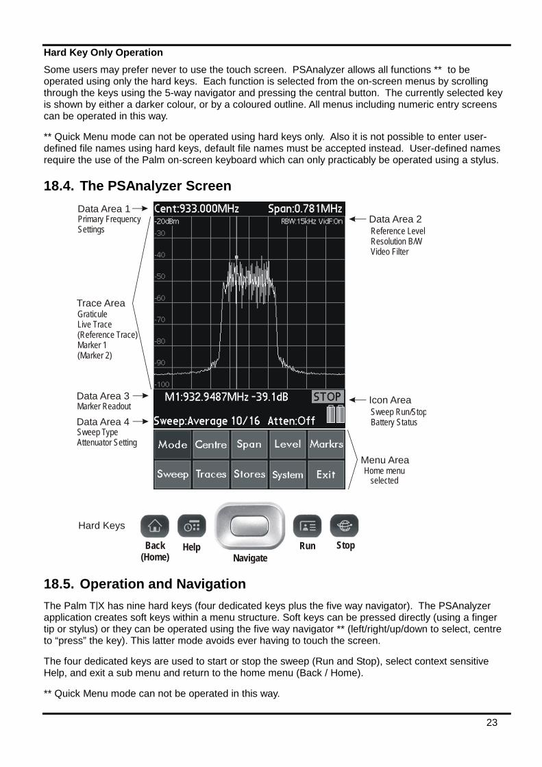
18.4. The PSAnalyzer Screen
Data Area 2
Icon Area
Data Area 1Primary Frequency Settings Reference Level
Resolution B/WVideo Filter
Sweep Run/StopBattery Status
Data Area 3
Data Area 4Marker Readout
Sweep TypeAttenuator Setting
Trace AreaGraticuleLive Trace(Reference Trace)Marker 1(Marker 2)
Menu AreaHome menu
selected
Back(Home)
Help Run StopNavigate
Hard Keys
18.5. Operation and Navigation The Palm T|X has nine hard keys (four dedicated keys plus the five way navigator). The PSAnalyzer application creates soft keys within a menu structure. Soft keys can be pressed directly (using a finger tip or stylus) or they can be operated using the five way navigator ** (left/right/up/down to select, centre to “press” the key). This latter mode avoids ever having to touch the screen.
The four dedicated keys are used to start or stop the sweep (Run and Stop), select context sensitive Help, and exit a sub menu and return to the home menu (Back / Home).
** Quick Menu mode can not be operated in this way.
24
18.6. Turning Off / Power Saving When operating from batteries the unit should be turned off when not in use. Press and hold the Back (Home) key. The display will go off, the status of the instrument is not lost and all data is retained apart from any running sweep. To turn back on, press the Back (Home) key again *. Alternatively use the recessed green on/off key on the top edge of the Palm T|X.
Note: an Auto Sleep function that automatically turns the unit off after a delay is available - see System menu, section 19.15. Auto Sleep is disabled whenever external power is connected.
* Note: When turning the unit back on, it may be necessary to press the key several times before it responds. This is because, in sleep mode, the keys are being polled very slowly as part of the power saving system.
19. The PSAnalyzer Menu System
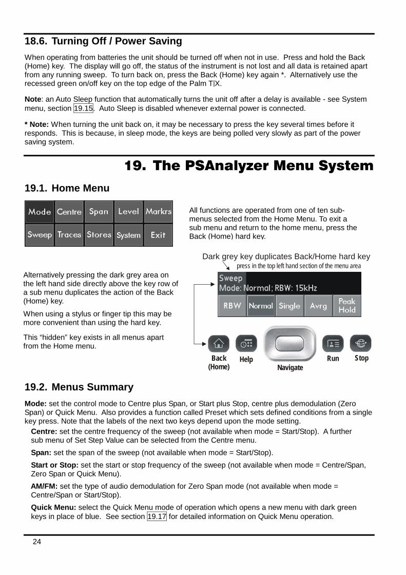
19.1. Home Menu
Dark grey key duplicates Back/Home hard keypress in the top left hand section of the menu area
Back(Home)
Help Run StopNavigate
19.2. Menus Summary Mode: set the control mode to Centre plus Span, or Start plus Stop, centre plus demodulation (Zero Span) or Quick Menu. Also provides a function called Preset which sets defined conditions from a single key press. Note that the labels of the next two keys depend upon the mode setting. Centre: set the centre frequency of the sweep (not available when mode = Start/Stop). A further sub menu of Set Step Value can be selected from the Centre menu. Span: set the span of the sweep (not available when mode = Start/Stop). Start or Stop: set the start or stop frequency of the sweep (not available when mode = Centre/Span, Zero Span or Quick Menu). AM/FM: set the type of audio demodulation for Zero Span mode (not available when mode = Centre/Span or Start/Stop). Quick Menu: select the Quick Menu mode of operation which opens a new menu with dark green keys in place of blue. See section 19.17 for detailed information on Quick Menu operation.
All functions are operated from one of ten sub-menus selected from the Home Menu. To exit a sub menu and return to the home menu, press the Back (Home) hard key.
Alternatively pressing the dark grey area on the left hand side directly above the key row of a sub menu duplicates the action of the Back (Home) key.
When using a stylus or finger tip this may be more convenient than using the hard key.
This “hidden” key exists in all menus apart from the Home menu.
25
Level: set reference level (by turning attenuator on or off); select display units (dBm or dBµV); select vertical zoom and pan. Markrs: set marker(s) on/off and position markers manually or automatically. Sweep: select sweep mode (Single, Normal (continuous), Peak Hold or Average), set RBW (resolution bandwidth). Traces: select Live and Reference traces, copy Live to Reference, select Limit Lines, set Video Filter, choose Hi or Lo resolution. Stores: store or recall a trace or a set-up, copy a whole screen to an image file, open the Limit Lines editor. System: set auto sleep mode, set sweep averaging number, turn graticule on or off. Exit: exit from the PSAnalyzer application or suspend the application (sleep mode); view information about the application.
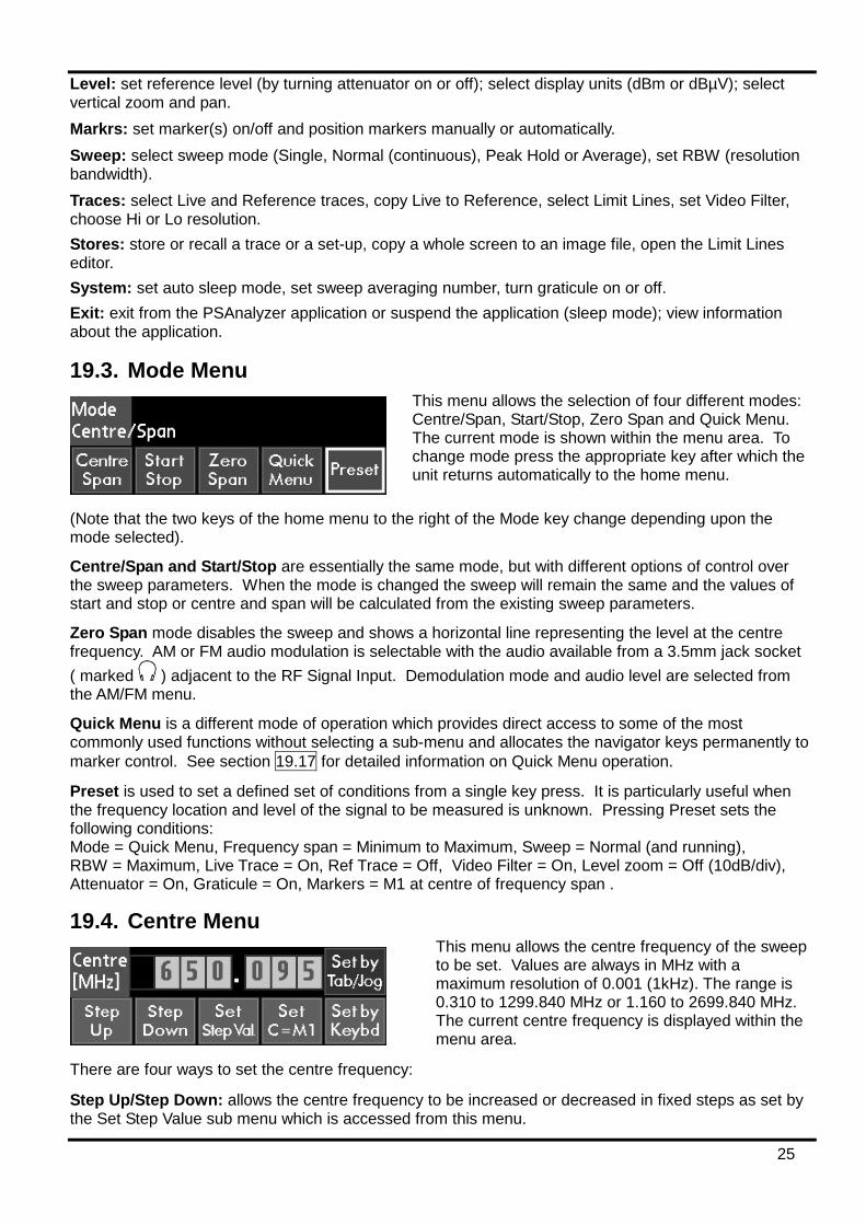
19.3. Mode Menu
(Note that the two keys of the home menu to the right of the Mode key change depending upon the mode selected).
Centre/Span and Start/Stop are essentially the same mode, but with different options of control over the sweep parameters. When the mode is changed the sweep will remain the same and the values of start and stop or centre and span will be calculated from the existing sweep parameters.
Zero Span mode disables the sweep and shows a horizontal line representing the level at the centre frequency. AM or FM audio modulation is selectable with the audio available from a 3.5mm jack socket ( marked ) adjacent to the RF Signal Input. Demodulation mode and audio level are selected from the AM/FM menu.
Quick Menu is a different mode of operation which provides direct access to some of the most commonly used functions without selecting a sub-menu and allocates the navigator keys permanently to marker control. See section 19.17 for detailed information on Quick Menu operation.
Preset is used to set a defined set of conditions from a single key press. It is particularly useful when the frequency location and level of the signal to be measured is unknown. Pressing Preset sets the following conditions: Mode = Quick Menu, Frequency span = Minimum to Maximum, Sweep = Normal (and running), RBW = Maximum, Live Trace = On, Ref Trace = Off, Video Filter = On, Level zoom = Off (10dB/div), Attenuator = On, Graticule = On, Markers = M1 at centre of frequency span .
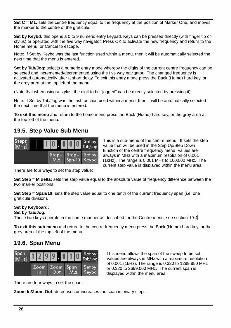
19.4. Centre Menu
There are four ways to set the centre frequency:
Step Up/Step Down: allows the centre frequency to be increased or decreased in fixed steps as set by the Set Step Value sub menu which is accessed from this menu.
This menu allows the centre frequency of the sweep to be set. Values are always in MHz with a maximum resolution of 0.001 (1kHz). The range is 0.310 to 1299.840 MHz or 1.160 to 2699.840 MHz. The current centre frequency is displayed within the menu area.
This menu allows the selection of four different modes: Centre/Span, Start/Stop, Zero Span and Quick Menu. The current mode is shown within the menu area. To change mode press the appropriate key after which the unit returns automatically to the home menu.
26
Set C = M1: sets the centre frequency equal to the frequency at the position of Marker One, and moves the marker to the centre of the graticule.
Set by Keybd: this opens a 0 to 9 numeric entry keypad. Keys can be pressed directly (with finger tip or stylus) or operated with the five way navigator. Press OK to activate the new frequency and return to the Home menu, or Cancel to escape.
Note: If Set by Keybd was the last function used within a menu, then it will be automatically selected the next time that the menu is entered.
Set by Tab/Jog: selects a numeric entry mode whereby the digits of the current centre frequency can be selected and incremented/decremented using the five way navigator. The changed frequency is activated automatically after a short delay. To exit this entry mode press the Back (Home) hard key, or the grey area at the top left of the menu.
(Note that when using a stylus, the digit to be “jogged” can be directly selected by pressing it).
Note: If Set by Tab/Jog was the last function used within a menu, then it will be automatically selected the next time that the menu is entered.
To exit this menu and return to the home menu press the Back (Home) hard key, or the grey area at the top left of the menu.
19.5. Step Value Sub Menu
There are four ways to set the step value:
Set Step = M delta: sets the step value equal to the absolute value of frequency difference between the two marker positions.
Set Step = Span/10: sets the step value equal to one tenth of the current frequency span (i.e. one graticule division).
Set by Keyboard: Set by Tab/Jog: These two keys operate in the same manner as described for the Centre menu, see section 19.4.
To exit this sub menu and return to the centre frequency menu press the Back (Home) hard key, or the grey area at the top left of the menu.
19.6. Span Menu
There are four ways to set the span:
Zoom In/Zoom Out: decreases or increases the span in binary steps.
This is a sub-menu of the centre menu. It sets the step value that will be used in the Step Up/Step Down function of the centre frequency menu Values are always in MHz with a maximum resolution of 0.001 (1kHz). The range is 0.001 MHz to 100.000 MHz. The current step value is displayed within the menu area.
This menu allows the span of the sweep to be set. Values are always in MHz with a maximum resolution of 0.001 (1kHz). The range is 0.320 to 1299.850 MHz or 0.320 to 2699.000 MHz. The current span is displayed within the menu area.
27
Span = M delta: sets the span equal to the absolute value of frequency difference between the two marker positions..
Set by Keyboard: Set by Tab/Jog: These two keys operate in the same manner as described for the Centre menu, see section 19.4.
To exit this menu and return to the home menu press the Back (Home) hard key, or the grey area at the top left of the menu.
19.7. Start Frequency Menu
There are four ways to set the start frequency:
Start = M1: sets the start frequency equal to the frequency at the position of Marker One.
Start = M1/Stop = M2: sets the start frequency equal to the frequency at the position of Marker One and the stop frequency equal to the frequency at the position of Marker Two (both markers must be active for this function to operate)
Set by Keyboard: Set by Tab/Jog: These two keys operate in the same manner as described for the Centre menu, see section 19.4.
To exit this menu and return to the home menu press the Back (Home) hard key, or the grey area at the top left of the menu.
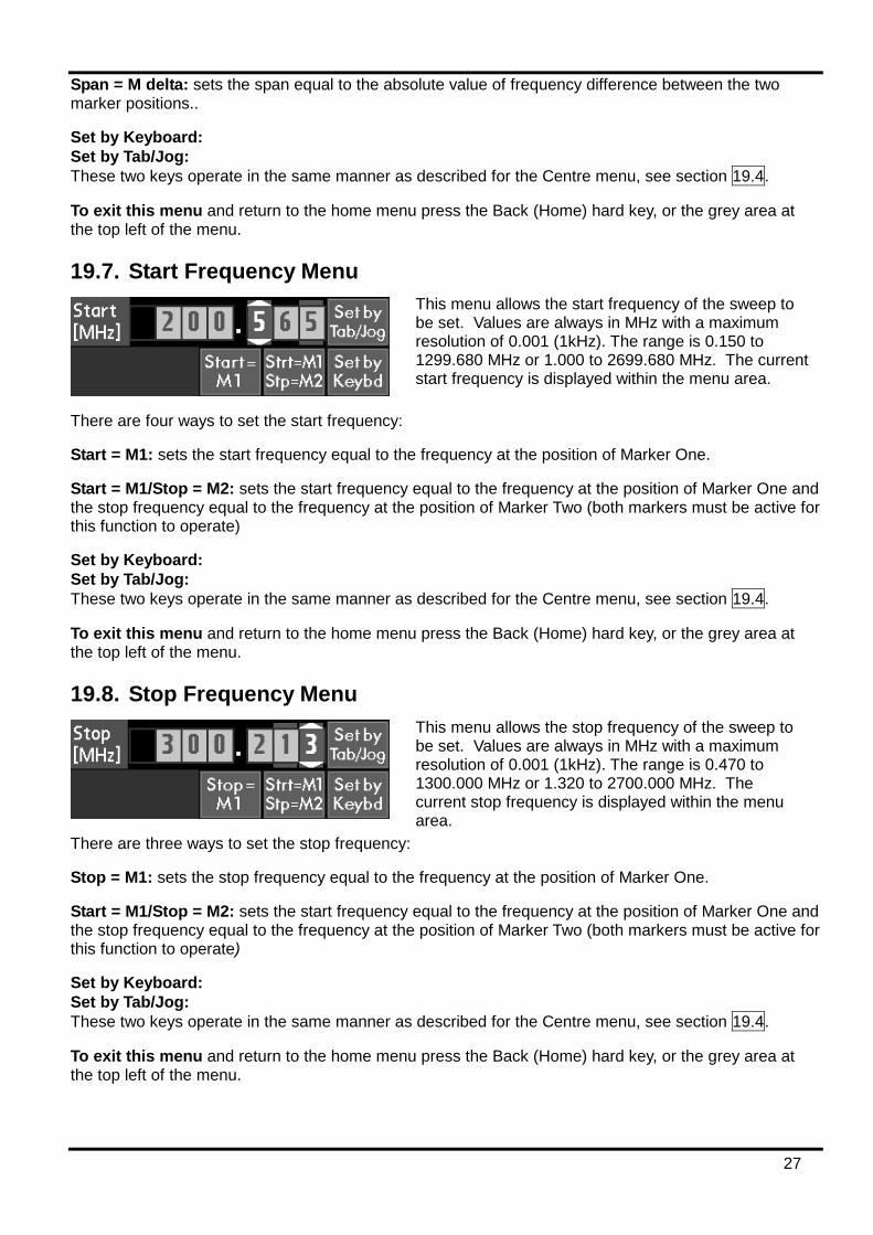
19.8. Stop Frequency Menu
There are three ways to set the stop frequency:
Stop = M1: sets the stop frequency equal to the frequency at the position of Marker One.
Start = M1/Stop = M2: sets the start frequency equal to the frequency at the position of Marker One and the stop frequency equal to the frequency at the position of Marker Two (both markers must be active for this function to operate)
Set by Keyboard: Set by Tab/Jog: These two keys operate in the same manner as described for the Centre menu, see section 19.4.
To exit this menu and return to the home menu press the Back (Home) hard key, or the grey area at the top left of the menu.
This menu allows the start frequency of the sweep to be set. Values are always in MHz with a maximum resolution of 0.001 (1kHz). The range is 0.150 to 1299.680 MHz or 1.000 to 2699.680 MHz. The current start frequency is displayed within the menu area.
This menu allows the stop frequency of the sweep to be set. Values are always in MHz with a maximum resolution of 0.001 (1kHz). The range is 0.470 to 1300.000 MHz or 1.320 to 2700.000 MHz. The current stop frequency is displayed within the menu area.
28
19.9. AM/FM Menu
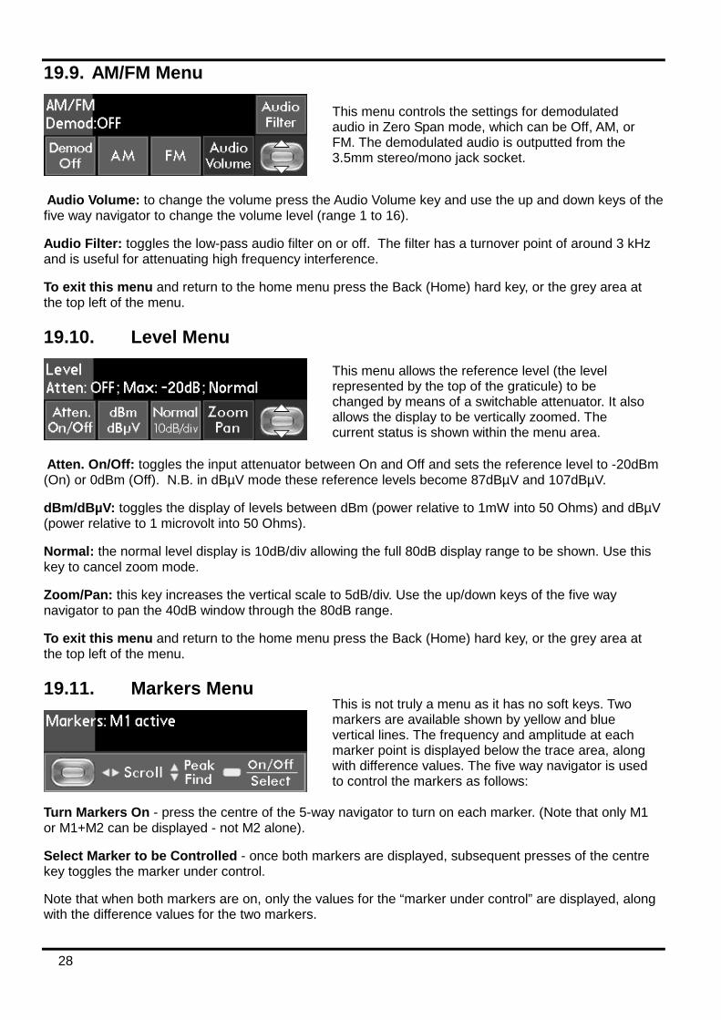
Audio Volume: to change the volume press the Audio Volume key and use the up and down keys of the five way navigator to change the volume level (range 1 to 16).
Audio Filter: toggles the low-pass audio filter on or off. The filter has a turnover point of around 3 kHz and is useful for attenuating high frequency interference.
To exit this menu and return to the home menu press the Back (Home) hard key, or the grey area at the top left of the menu.
19.10. Level Menu
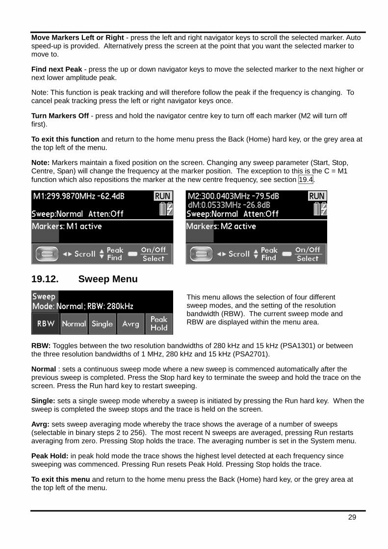
Atten. On/Off: toggles the input attenuator between On and Off and sets the reference level to -20dBm (On) or 0dBm (Off). N.B. in dBµV mode these reference levels become 87dBµV and 107dBµV.
dBm/dBµV: toggles the display of levels between dBm (power relative to 1mW into 50 Ohms) and dBµV (power relative to 1 microvolt into 50 Ohms).
Normal: the normal level display is 10dB/div allowing the full 80dB display range to be shown. Use this key to cancel zoom mode.
Zoom/Pan: this key increases the vertical scale to 5dB/div. Use the up/down keys of the five way navigator to pan the 40dB window through the 80dB range.
To exit this menu and return to the home menu press the Back (Home) hard key, or the grey area at the top left of the menu.
19.11. Markers Menu
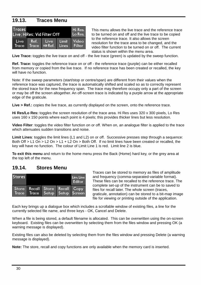
Turn Markers On - press the centre of the 5-way navigator to turn on each marker. (Note that only M1 or M1+M2 can be displayed - not M2 alone).
Select Marker to be Controlled - once both markers are displayed, subsequent presses of the centre key toggles the marker under control.
Note that when both markers are on, only the values for the “marker under control” are displayed, along with the difference values for the two markers.
This menu controls the settings for demodulated audio in Zero Span mode, which can be Off, AM, or FM. The demodulated audio is outputted from the 3.5mm stereo/mono jack socket.
This menu allows the reference level (the level represented by the top of the graticule) to be changed by means of a switchable attenuator. It also allows the display to be vertically zoomed. The current status is shown within the menu area.
This is not truly a menu as it has no soft keys. Two markers are available shown by yellow and blue vertical lines. The frequency and amplitude at each marker point is displayed below the trace area, along with difference values. The five way navigator is used to control the markers as follows:
29
Move Markers Left or Right - press the left and right navigator keys to scroll the selected marker. Auto speed-up is provided. Alternatively press the screen at the point that you want the selected marker to move to.
Find next Peak - press the up or down navigator keys to move the selected marker to the next higher or next lower amplitude peak.
Note: This function is peak tracking and will therefore follow the peak if the frequency is changing. To cancel peak tracking press the left or right navigator keys once.
Turn Markers Off - press and hold the navigator centre key to turn off each marker (M2 will turn off first).
To exit this function and return to the home menu press the Back (Home) hard key, or the grey area at the top left of the menu.
Note: Markers maintain a fixed position on the screen. Changing any sweep parameter (Start, Stop, Centre, Span) will change the frequency at the marker position. The exception to this is the C = M1 function which also repositions the marker at the new centre frequency, see section 19.4.
19.12. Sweep Menu
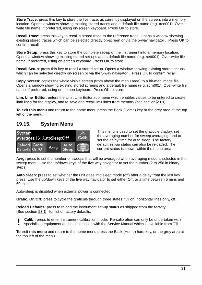
RBW: Toggles between the two resolution bandwidths of 280 kHz and 15 kHz (PSA1301) or between the three resolution bandwidths of 1 MHz, 280 kHz and 15 kHz (PSA2701).
Normal : sets a continuous sweep mode where a new sweep is commenced automatically after the previous sweep is completed. Press the Stop hard key to terminate the sweep and hold the trace on the screen. Press the Run hard key to restart sweeping.
Single: sets a single sweep mode whereby a sweep is initiated by pressing the Run hard key. When the sweep is completed the sweep stops and the trace is held on the screen.
Avrg: sets sweep averaging mode whereby the trace shows the average of a number of sweeps (selectable in binary steps 2 to 256). The most recent N sweeps are averaged, pressing Run restarts averaging from zero. Pressing Stop holds the trace. The averaging number is set in the System menu.
Peak Hold: in peak hold mode the trace shows the highest level detected at each frequency since sweeping was commenced. Pressing Run resets Peak Hold. Pressing Stop holds the trace.
To exit this menu and return to the home menu press the Back (Home) hard key, or the grey area at the top left of the menu.
This menu allows the selection of four different sweep modes, and the setting of the resolution bandwidth (RBW). The current sweep mode and RBW are displayed within the menu area.
30
19.13. Traces Menu
Live Trace: toggles the live trace on and off - the live trace (green) is updated by the sweep function.
Ref. Trace: toggles the reference trace on or off - the reference trace (purple) can be either recalled from memory or copied from the live trace. If no reference trace has been created or recalled, the key will have no function.
Note: If the sweep parameters (start/stop or centre/span) are different from their values when the reference trace was captured, the trace is automatically shifted and scaled so as to correctly represent the stored trace for the new frequency span. The trace may therefore occupy only a part of the screen or may be off the screen altogether. An off-screen trace is indicated by a purple arrow at the appropriate edge of the graticule.
Live > Ref.: copies the live trace, as currently displayed on the screen, onto the reference trace.
Hi Res/Lo Res: toggles the screen resolution of the trace area. Hi Res uses 320 x 300 pixels, Lo Res uses 160 x 150 points where each point is 4 pixels; this provides thicker lines but less resolution.
Video Filter: toggles the video filter function on or off. When on, an analogue filter is applied to the trace which attenuates sudden transitions and noise.
Limit Lines: toggles the limit lines (L1 and L2) on or off. Successive presses step through a sequence: Both Off > L1 On > L2 On > L1 + L2 On > Both Off. If no limit lines have been created or recalled, the key will have no function. The colour of Limit Line 1 is red. Limit line 2 is blue.
To exit this menu and return to the home menu press the Back (Home) hard key, or the grey area at the top left of the menu.
19.14. Stores Menu
Each key brings up a dialogue box which includes a scrollable window of existing files, a line for the currently selected file name, and three keys - OK, Cancel and Delete.
When a file is being stored, a default filename is allocated. This can be overwritten using the on-screen keyboard. Existing files can be overwritten by selecting them from the files window and pressing OK (a warning message is displayed).
Existing files can also be deleted by selecting them from the files window and pressing Delete (a warning message is displayed).
Note: The store, recall and copy functions are only available when the memory card is inserted.
This menu allows the live trace and the reference trace to be turned on and off and the live trace to be copied to the reference trace. It also allows the screen resolution for the trace area to be changed, and the video filter function to be turned on or off. The current status is shown within the menu area.
Traces can be stored to memory as files of amplitude and frequency (comma-separated-variable format). These files can be recalled to the reference trace. The complete set-up of the instrument can be to saved to files for recall later. The whole screen (traces, graticule, annotation) can be stored to a bit-map image file for viewing or printing outside of the application.
31
Store Trace: press this key to store the live trace, as currently displayed on the screen, into a memory location. Opens a window showing existing stored traces and a default file name (e.g. trce001). Over-write file name, if preferred, using on-screen keyboard. Press OK to store.
Recall Trace: press this key to recall a stored trace to the reference trace. Opens a window showing existing stored traces which can be selected directly on-screen or via the 5-way navigator . Press OK to confirm recall.
Store Setup: press this key to store the complete set-up of the instrument into a memory location. Opens a window showing existing stored set-ups and a default file name (e.g. sett001). Over-write file name, if preferred, using on-screen keyboard. Press OK to store.
Recall Setup: press this key to recall a stored setup. Opens a window showing existing stored setups which can be selected directly on-screen or via the 5-way navigator . Press OK to confirm recall.
Copy Screen: copies the whole visible screen (from above the menu area) to a bit-map image file. Opens a window showing existing stored screens and a default file name (e.g. scrn001). Over-write file name, if preferred, using on-screen keyboard. Press OK to store.
Lim. Line Editor: enters the Limit Line Editor sub menu which enables values to be entered to create limit lines for the display, and to save and recall limit lines from memory (see section 20.9).
To exit this menu and return to the home menu press the Back (Home) key or the grey area at the top left of the menu..
19.15. System Menu
Avrg: press to set the number of sweeps that will be averaged when averaging mode is selected in the sweep menu. Use the up/down keys of the five way navigator to set the number (2 to 256 in binary steps).
Auto Sleep: press to set whether the unit goes into sleep mode (off) after a delay from the last key press. Use the up/down keys of the five way navigator to set either Off, or a time between 5 mins and 60 mins.
Auto-sleep is disabled when external power is connected.
Gratic. On/Off: press to cycle the graticule through three states: full on, horizontal lines only, off.
Reload Defaults: press to reload the instrument set-up status as shipped from the factory. (See section 23.1 - for list of factory defaults.
Calib.: press to enter instrument calibration mode. Re-calibration can only be undertaken with specialised equipment and in conjunction with the Service Manual which is available from TTi.
To exit this menu and return to the home menu press the Back (Home) hard key, or the grey area at the top left of the menu.
This menu is used to set the graticule display, set the averaging number for sweep averaging, and to set the delay time for auto sleep. The factory default set-up status can also be reloaded. The current status is shown within the menu area.
32
19.16. Exit Menu
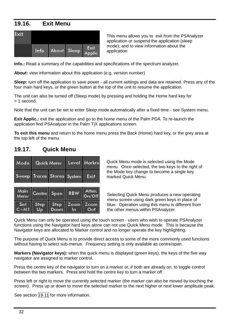
Info.: Read a summary of the capabilities and specifications of the spectrum analyzer.
About: view information about this application (e.g. version number)
Sleep: turn off the application to save power - all current settings and data are retained. Press any of the four main hard keys, or the green button at the top of the unit to resume the application.
The unit can also be turned off (Sleep mode) by pressing and holding the Home hard key for > 1 second.
Note that the unit can be set to enter Sleep mode automatically after a fixed time - see System menu.
Exit Applic.: exit the application and go to the home menu of the Palm PDA. To re-launch the application find PSAnalyzer in the Palm T|X applications screen.
To exit this menu and return to the home menu press the Back (Home) hard key, or the grey area at the top left of the menu.
19.17. Quick Menu
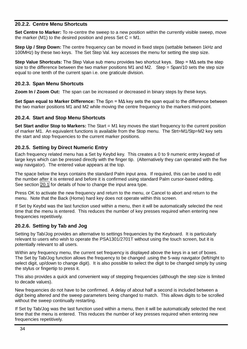
Quick Menu can only be operated using the touch screen - users who wish to operate PSAnalyzer functions using the Navigator hard keys alone can not use Quick Menu mode. This is because the Navigator keys are allocated to Marker control and no longer operate the key highlighting.
The purpose of Quick Menu is to provide direct access to some of the more commonly used functions without having to select sub-menus. Frequency setting is only available as centre/span.
Markers (Navigator keys): when the quick menu is displayed (green keys), the keys of the five way navigator are assigned to marker control.
Press the centre key of the navigator to turn on a marker or, if both are already on, to toggle control between the two markers. Press and hold the centre key to turn a marker off.
Press left or right to move the currently selected marker (the marker can also be moved by touching the screen). Press up or down to move the selected marker to the next higher or next lower amplitude peak.
See section 19.11 for more information.
This menu allows you to exit from the PSAnalyzer application or suspend the application (sleep mode); and to view information about the application
Quick Menu mode is selected using the Mode menu. Once selected, the two keys to the right of the Mode key change to become a single key marked Quick Menu.
Selecting Quick Menu produces a new operating menu screen using dark green keys in place of blue. Operation using this menu is different from the other menus within PSAnalyzer.

33
Main Menu: return to the main (home) menu in order to access functions that are not available from Quick Menu, or to select a different mode.
Centre: enter the Centre frequency menu for selecting the centre frequency of the sweep or setting the step size. See section 19.4.
Span: enter the Span menu for setting the frequency span of the sweep. See section 19.6.
RBW: toggle the resolution bandwidth between 280 kHz and 15 kHz (PSA1301T) or between 1 MHz, 280 kHz and 15 kHz (PSA2701T). The value is displayed at the top right of the graticule area.
Atten. On/Off: toggle the attenuator between On (reference level = 0dBm) and Off (reference level = -20dBm). The reference level is displayed at the top left of the graticule area.
Set C = M1: set the centre frequency equal to the frequency at the position of Marker One, and move the cursor to the centre of screen.
Step Up/Step Down: increase or decrease the centre frequency in fixed steps as set by the Set Step Value sub menu which is accessed from the Centre menu
Zoom In/Zoom Out: decrease or increase the span in binary steps.
20. PSAnalyzer Operating Techniques The following section contains some tips and hints regarding the operation of the PSA1301/2701T. Each individual menu function is detailed within section 19 "The PSAnalyzer Menu System". Information is also provided in the context sensitive Help on the instrument.
20.1. Menu Navigation The Hidden Key: PSAnalyzer is controlled via the ten operating menus, see section 19. Moving between menus requires a return to the Home menu by pressing the Back (Home) hard key. When using the touch screen for control (rather than the 5-way navigator), it is also possible to use the “hidden” key which is the dark grey area at the top LH side of each menu. This duplicates the action of the Back (Home) hard key.
The Menu Highlight Position: When using the 5-way navigator for control, pressing the select button operates the currently highlighted key. On leaving a menu, this position is remembered and is recalled when the menu is next entered. Thus, if Start = M1 was the last function used within the Start menu, it can be operated again by highlighting Start in the Home menu and pressing the selector button twice.
Note that using the 5-way navigator for key control cannot be done in Quick Menu mode.
20.2. Frequency Setting 20.2.1. Centre/Span and Start/Stop modes PSAnalyzer has four “modes” of operation selected from the Mode menu: Centre/Span, Start/Stop, Zero Span and Quick Menu.
Centre/Span and Start/Stop are not actually different sweep modes. Rather, they are different modes for setting and displaying the sweep parameters. The user can change between these two modes at any time without altering the sweep (apart from causing it to restart). The only effect will be to change the information directly above the graticule area, and the two menu keys to the right of the Mode key.
Quick Menu is a variant of centre/span mode which gives direct access to some commonly used functions without the need to enter sub-menus. It also allocates navigator keys permanently to marker control. See section 19.17 for details.
34
20.2.2. Centre Menu Shortcuts Set Centre to Marker: To re-centre the sweep to a new position within the currently visible sweep, move the marker (M1) to the desired position and press Set C = M1.
Step Up / Step Down: The centre frequency can be moved in fixed steps (settable between 1kHz and 100MHz) by these two keys. The Set Step Val. key accesses the menu for setting the step size.
Step Value Shortcuts: The Step Value sub menu provides two shortcut keys. Step = MΔ sets the step size to the difference between the two marker positions M1 and M2. Step = Span/10 sets the step size equal to one tenth of the current span i.e. one graticule division.
20.2.3. Span Menu Shortcuts Zoom In / Zoom Out: The span can be increased or decreased in binary steps by these keys.
Set Span equal to Marker Difference: The Spn = MΔ key sets the span equal to the difference between the two marker positions M1 and M2 while moving the centre frequency to the markers mid-point.
20.2.4. Start and Stop Menu Shortcuts Set Start and/or Stop to Markers: The Start = M1 key moves the start frequency to the current position of marker M1. An equivalent functions is available from the Stop menu. The Strt=M1/Stp=M2 key sets the start and stop frequencies to the current marker positions.
20.2.5. Setting by Direct Numeric Entry Each frequency related menu has a Set by Keybd key. This creates a 0 to 9 numeric entry keypad of large keys which can be pressed directly with the finger tip. (Alternatively they can operated with the five way navigator). The entered value appears at the top.
The space below the keys contains the standard Palm input area. If required, this can be used to edit the number after it is entered and before it is confirmed using standard Palm cursor-based editing. See section 20.1 for details of how to change the input area type.
Press OK to activate the new frequency and return to the menu, or Cancel to abort and return to the menu. Note that the Back (Home) hard key does not operate within this screen.
If Set by Keybd was the last function used within a menu, then it will be automatically selected the next time that the menu is entered. This reduces the number of key presses required when entering new frequencies repetitively.
20.2.6. Setting by Tab and Jog Setting by Tab/Jog provides an alternative to settings frequencies by the Keyboard. It is particularly relevant to users who wish to operate the PSA1301/2701T without using the touch screen, but it is potentially relevant to all users.
Within any frequency menu, the current set frequency is displayed above the keys in a set of boxes. The Set by Tab/Jog function allows the frequency to be changed .using the 5-way navigator (left/right to select digit, up/down to change digit). It is also possible to select the digit to be changed simply by using the stylus or fingertip to press it.
This also provides a quick and convenient way of stepping frequencies (although the step size is limited to decade values).
New frequencies do not have to be confirmed. A delay of about half a second is included between a digit being altered and the sweep parameters being changed to match. This allows digits to be scrolled without the sweep continually restarting.
If Set by Tab/Jog was the last function used within a menu, then it will be automatically selected the next time that the menu is entered. This reduces the number of key presses required when entering new frequencies repetitively.
35
20.3. Performing Sweeps Frequency sweeps are started and stopped using the hard keys Run and Stop. The Sweep menu permits four different sweep types to be selected, and allows the resolution bandwidth to be changed, see section 19.12.
The Stop key halts the sweep at any time and holds the trace. The Run key initiates a new sweep and also resets Averaging and Peak Hold sweep modes. (Note that the averaging value is selected from the System menu rather than the Sweep menu).
When the sweep is in Stop, any change to the sweep frequency settings or to the attenuator setting will initiate a new single sweep. This is done to ensure that the live trace remains correct relative to the graticule markings.
Sweep Rate and Update Mode There is no user control of the sweep rate. The speed of sweeping is determined by the frequency span and the resolution bandwidth; the analyzer sweeps at the fastest rate possible for the Span and RBW selected, subject to a maximum rate of approximately 5Hz.
The approximate sweep time can be calculated from the following formulae (span in MHz): For RBW = 1MHz (PSA2701 only), sweep time = 200ms + (span x 2ms) For RBW = 280kHz, sweep time = 200ms + (span x 7ms) For RBW = 15kHz, sweep time = 200ms + (span x 75ms)
Thus, for example, a sweep of 10MHz span at 15kHz RBW will take about 1 second; whilst a sweep of 1GHz span will take around 8 seconds at 280kHz RBW, or 2 seconds at 1MHz RBW.
Note that for fast sweeps (less than 0.67 seconds) the display is updated at the end of the sweep with all points re-written simultaneously. For slower sweeps, the display is updated synchronously with the sweep and the old sweep values are sequentially over-written with the new values. In this mode the progress of the sweep is indicated by a moving yellow line at the bottom of the graticule.
Video Filter
The video filter has only two settings, on or off. The setting has no effect on the sweep rate.
By default the video filter is turned On. At 280kHz/1MHz RBW this reduces the effects of system noise within the PSA1301/2701 and improves the identification of low level signals just above the noise floor. The filter attenuates noise signals above about 10kHz. It has a negligible effect on peak amplitude measurements for signals at -60dB below the reference level or higher.
Where users wish to evaluate the noise performance of the system under test, they may wish to turn the video filter Off.
At 15kHz RBW the effect of the video filter is small.
20.4. Level Measurements The normal display has a range of 80 dBs down from the top of the graticule (the reference level). The reference level is set from the Level menu, see section 19.10. With the attenuator off, the reference level is -20dBm, with the attenuator on it is 0dBm.
Although RF signal measurements are most commonly made in dBm (power relative to 1 milliwatt into 50 Ohms), EMC measurements are normally made in dBµV (power relative to 1 microvolt into 50 Ohms). The dBm/dBµV key toggles between these two measurement modes.
Note that, in dBµV mode, the top-of graticule reference becomes 87dBµV (-20dBm) with the attenuator off, and 107dBµV (0dBm) with the attenuator on. The graticule lines are shifted so that subsequent lines are in multiples of 10dBµV.
Note that any signal levels above the reference level can cause non-linearity in the detectors which could affect the amplitude accuracy of other signals which are below the reference level.
36
An overload indicator is provided to show this condition. The indicator is a red upwards pointing arrow near the top of the graticule.
The absolute maximum signal level that can be applied without damage is specified as +20dBm or 127dBµV (approx. 2.2V rms).
The display can be vertically expanded using the Zoom/Pan function. Zoom has a single level of x2, and the 40dB window can be panned over the full range using the 5-way navigator. Note that this function is for viewing purposes only and provides no improvement in accuracy or resolution, the latter being fixed at 0.1dB.
20.5. The PRESET Key The Preset key is found within the Mode menu, see section 19.3. It has a yellow outline to signify that it changes several things simultaneously.
Preset is used to set a defined set of conditions from a single key press. It is particularly useful when the frequency and amplitude of the signal is unknown, or when the existing status of the unit is unknown as might be the case when the PSA1301/2701T is being shared between several users.
Pressing Preset sets the following conditions: Mode = Quick Menu, Frequency span = Minimum to Maximum, Sweep = Normal (and running), RBW = Maximum, Live Trace = On, Ref Trace = Off, Video Filter = On, Level zoom = Off (10dB/div), Attenuator = On, Graticule = On, Markers = M1 on at centre of the span . An alternative to using the Preset key is to reload factory defaults (from the system menu). This resets all of the settings to a known state including system settings such as screen resolution. See section 23.1.
20.6. Using Markers Markers provide a numeric readout of amplitude and frequency. Activation and control of markers using the Markers menu is described in section 19.11.
Markers are vertical lines with a box that highlights the intersection point of the marker with the trace. The readout shows the frequency and level at the intersection point. When both markers are displayed, the frequency and amplitude difference is also displayed. Markers provide an amplitude readout for the live trace only.
Markers also provide a quick and accurate method of resetting centre, span, start or stop frequencies to examine an area of interest. See section 20.2.
Although the frequency readout has a resolution of 0.1kHz, the uncertainty of the frequency at any sweep point is related to the span, being approximately 0.3% of the span width (span/320).
Note that markers retain their position relative to the graticule. When the sweep range is changed, the marker frequencies change with them.
Peak Find and Track: The Peak Find function (5-way navigator up/down) will automatically move the selected marker to the position of the highest amplitude peak. Thereafter pressing navigator down will move the marker to the next amplitude peak (regardless of its position on the screen), and so on downwards in amplitude. Pressing navigator up will move it through peaks of increasing amplitude.
The function will automatically track the signal. For each new sweep, the marker moves to follow its current peak position. If it is currently marking the third highest amplitude level, it will move to the position of the new third highest amplitude level when the signal changes. Only the currently selected marker will peak track.
Peak find/track is cancelled when the marker is moved manually, the selected marker is changed, or when any sweep parameter is changed.
Marker Movement Shortcut: When the Markers menu is selected (or when in Quick Menu mode), the active marker can be moved by touching the screen at the desired position.
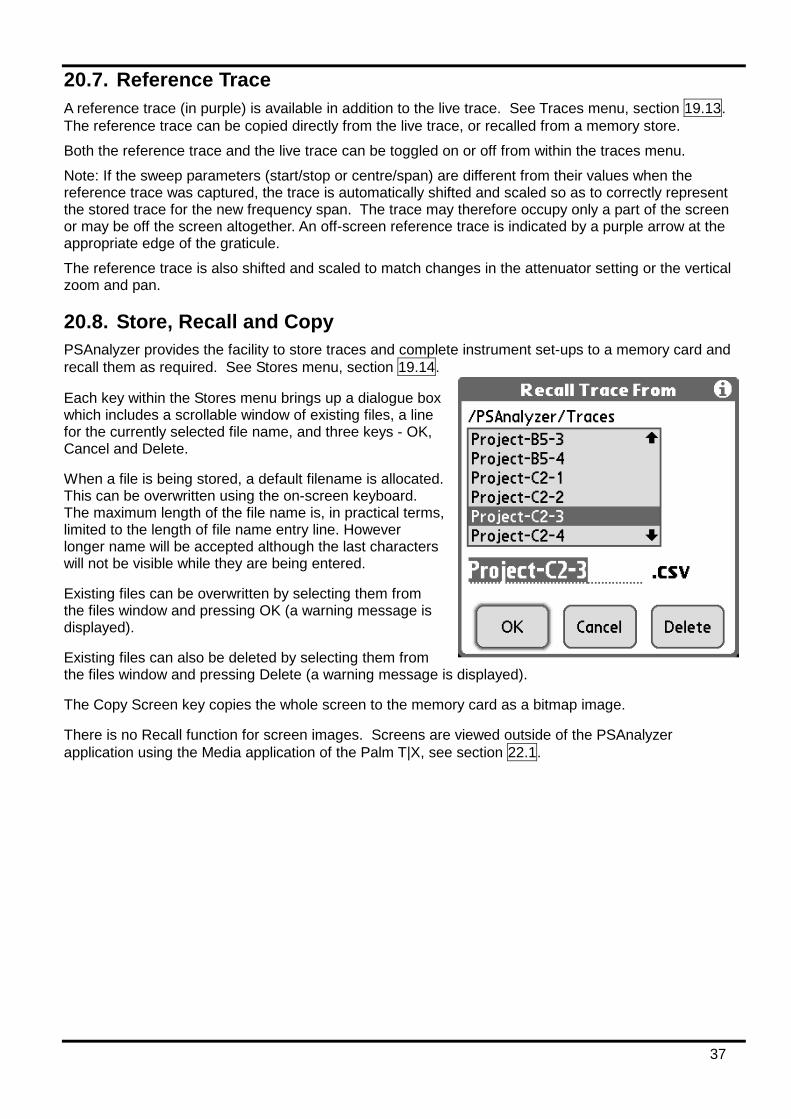
37
20.7. Reference Trace A reference trace (in purple) is available in addition to the live trace. See Traces menu, section 19.13. The reference trace can be copied directly from the live trace, or recalled from a memory store.
Both the reference trace and the live trace can be toggled on or off from within the traces menu.
Note: If the sweep parameters (start/stop or centre/span) are different from their values when the reference trace was captured, the trace is automatically shifted and scaled so as to correctly represent the stored trace for the new frequency span. The trace may therefore occupy only a part of the screen or may be off the screen altogether. An off-screen reference trace is indicated by a purple arrow at the appropriate edge of the graticule.
The reference trace is also shifted and scaled to match changes in the attenuator setting or the vertical zoom and pan.
20.8. Store, Recall and Copy PSAnalyzer provides the facility to store traces and complete instrument set-ups to a memory card and recall them as required. See Stores menu, section 19.14.
Each key within the Stores menu brings up a dialogue box which includes a scrollable window of existing files, a line for the currently selected file name, and three keys - OK, Cancel and Delete.
When a file is being stored, a default filename is allocated. This can be overwritten using the on-screen keyboard. The maximum length of the file name is, in practical terms, limited to the length of file name entry line. However longer name will be accepted although the last characters will not be visible while they are being entered.
Existing files can be overwritten by selecting them from the files window and pressing OK (a warning message is displayed).
Existing files can also be deleted by selecting them from the files window and pressing Delete (a warning message is displayed).
The Copy Screen key copies the whole screen to the memory card as a bitmap image.
There is no Recall function for screen images. Screens are viewed outside of the PSAnalyzer application using the Media application of the Palm T|X, see section 22.1.
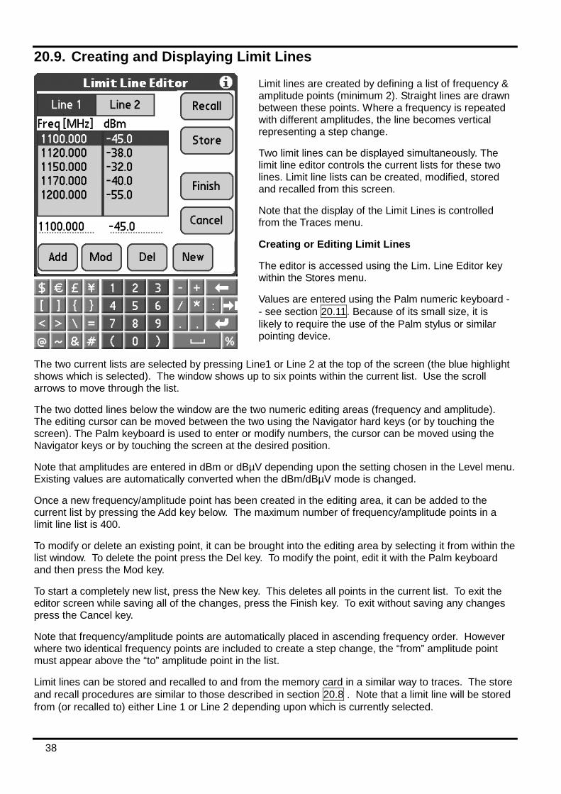
38
20.9. Creating and Displaying Limit Lines
The two current lists are selected by pressing Line1 or Line 2 at the top of the screen (the blue highlight shows which is selected). The window shows up to six points within the current list. Use the scroll arrows to move through the list.
The two dotted lines below the window are the two numeric editing areas (frequency and amplitude). The editing cursor can be moved between the two using the Navigator hard keys (or by touching the screen). The Palm keyboard is used to enter or modify numbers, the cursor can be moved using the Navigator keys or by touching the screen at the desired position.
Note that amplitudes are entered in dBm or dBµV depending upon the setting chosen in the Level menu. Existing values are automatically converted when the dBm/dBµV mode is changed.
Once a new frequency/amplitude point has been created in the editing area, it can be added to the current list by pressing the Add key below. The maximum number of frequency/amplitude points in a limit line list is 400.
To modify or delete an existing point, it can be brought into the editing area by selecting it from within the list window. To delete the point press the Del key. To modify the point, edit it with the Palm keyboard and then press the Mod key.
To start a completely new list, press the New key. This deletes all points in the current list. To exit the editor screen while saving all of the changes, press the Finish key. To exit without saving any changes press the Cancel key.
Note that frequency/amplitude points are automatically placed in ascending frequency order. However where two identical frequency points are included to create a step change, the “from” amplitude point must appear above the “to” amplitude point in the list.
Limit lines can be stored and recalled to and from the memory card in a similar way to traces. The store and recall procedures are similar to those described in section 20.8 . Note that a limit line will be stored from (or recalled to) either Line 1 or Line 2 depending upon which is currently selected.
Limit lines are created by defining a list of frequency & amplitude points (minimum 2). Straight lines are drawn between these points. Where a frequency is repeated with different amplitudes, the line becomes vertical representing a step change.
Two limit lines can be displayed simultaneously. The limit line editor controls the current lists for these two lines. Limit line lists can be created, modified, stored and recalled from this screen.
Note that the display of the Limit Lines is controlled from the Traces menu.
Creating or Editing Limit Lines
The editor is accessed using the Lim. Line Editor key within the Stores menu.
Values are entered using the Palm numeric keyboard - - see section 20.11. Because of its small size, it is likely to require the use of the Palm stylus or similar pointing device.
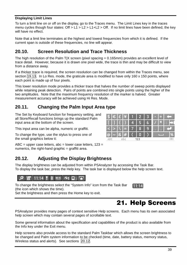
39
Displaying Limit Lines To turn a limit line on or off on the display, go to the Traces menu. The Limit Lines key in the traces menu cycles though four states: Off > L1 > L2 > L1+L2 > Off. If no limit lines have been defined, the key will have no effect.
Note that a limit line terminates at the highest and lowest frequencies from which it is defined. If the current span is outside of these frequencies, no line will appear.
20.10. Screen Resolution and Trace Thickness The high resolution of the Palm T|X screen (pixel spacing = 0.165mm) provides an excellent level of trace detail. However, because it is drawn one pixel wide, the trace is thin and may be difficult to view from a distance away.
If a thicker trace is required, the screen resolution can be changed from within the Traces menu, see section 19.13. In Lo Res. mode, the graticule area is modified to have only 160 x 150 points, where each point is made up of four pixels.
This lower resolution mode provides a thicker trace that halves the number of sweep points displayed while retaining peak detection. Pairs of points are combined into single points using the higher of the two amplitudes. Note that the maximum frequency resolution of the marker is halved. Greater measurement accuracy will be achieved using Hi Res. Mode.
20.11. Changing the Palm Input Area type The Set by Keyboard function for frequency setting, and all Store/Recall functions brings up the standard Palm input area at the bottom of the screen.
This input area can be alpha, numeric or graffiti.
To change the type, use the stylus to press one of the small graphics below it:
ABC = upper case letters, abc = lower case letters, 123 = numerics, the right-hand graphic = graffiti area.
20.12. Adjusting the Display Brightness The display brightness can be adjusted from within PSAnalyzer by accessing the Task Bar. To display the task bar, press the Help key. The task bar is displayed below the help screen text.
To change the brightness select the “System Info” icon from the Task Bar (the icon which shows the time). Set the brightness and then press the Home key to exit.
21. Help Screens PSAnalyzer provides many pages of context sensitive Help screens. Each menu has its own associated help screen which may contain several pages of scrollable text.
Some general information about the specification and capabilities of the product is also available from the Info key under the Exit menu.
Help screens also provide access to the standard Palm Taskbar which allows the screen brightness to be changed and Palm system information to be checked (time, date, battery status, memory status, Wireless status and alerts). See sections 20.12.
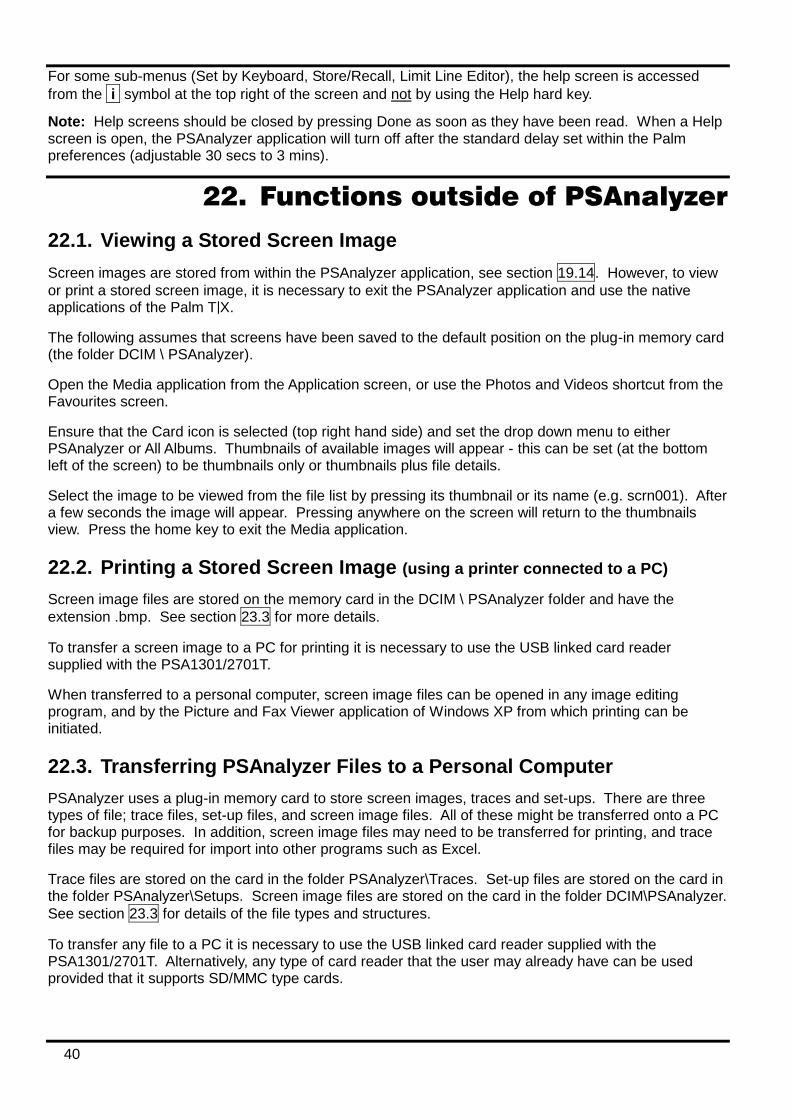
40
For some sub-menus (Set by Keyboard, Store/Recall, Limit Line Editor), the help screen is accessed from the i symbol at the top right of the screen and not by using the Help hard key.
Note: Help screens should be closed by pressing Done as soon as they have been read. When a Help screen is open, the PSAnalyzer application will turn off after the standard delay set within the Palm preferences (adjustable 30 secs to 3 mins).
22. Functions outside of PSAnalyzer
22.1. Viewing a Stored Screen Image Screen images are stored from within the PSAnalyzer application, see section 19.14. However, to view or print a stored screen image, it is necessary to exit the PSAnalyzer application and use the native applications of the Palm T|X.
The following assumes that screens have been saved to the default position on the plug-in memory card (the folder DCIM \ PSAnalyzer).
Open the Media application from the Application screen, or use the Photos and Videos shortcut from the Favourites screen.
Ensure that the Card icon is selected (top right hand side) and set the drop down menu to either PSAnalyzer or All Albums. Thumbnails of available images will appear - this can be set (at the bottom left of the screen) to be thumbnails only or thumbnails plus file details.
Select the image to be viewed from the file list by pressing its thumbnail or its name (e.g. scrn001). After a few seconds the image will appear. Pressing anywhere on the screen will return to the thumbnails view. Press the home key to exit the Media application.
22.2. Printing a Stored Screen Image (using a printer connected to a PC) Screen image files are stored on the memory card in the DCIM \ PSAnalyzer folder and have the extension .bmp. See section 23.3 for more details.
To transfer a screen image to a PC for printing it is necessary to use the USB linked card reader supplied with the PSA1301/2701T.
When transferred to a personal computer, screen image files can be opened in any image editing program, and by the Picture and Fax Viewer application of Windows XP from which printing can be initiated.
22.3. Transferring PSAnalyzer Files to a Personal Computer PSAnalyzer uses a plug-in memory card to store screen images, traces and set-ups. There are three types of file; trace files, set-up files, and screen image files. All of these might be transferred onto a PC for backup purposes. In addition, screen image files may need to be transferred for printing, and trace files may be required for import into other programs such as Excel.
Trace files are stored on the card in the folder PSAnalyzer\Traces. Set-up files are stored on the card in the folder PSAnalyzer\Setups. Screen image files are stored on the card in the folder DCIM\PSAnalyzer. See section 23.3 for details of the file types and structures.
To transfer any file to a PC it is necessary to use the USB linked card reader supplied with the PSA1301/2701T. Alternatively, any type of card reader that the user may already have can be used provided that it supports SD/MMC type cards.
41
22.3.1. Using the Memory Card Reader TTi provides a USB linked memory card reader to allow PSAnalyzer user files to be transferred to and from a personal computer.
The type of card reader supplied may vary from time to time. It may be a single card type (SD and MMC cards only) or a multi-card type. A USB extension lead may also be provided for card readers which do not have their own flexible connection lead.
Installation
No driver files should be required for installation under Windows 7, Windows Vista, Windows XP, Windows 2000, Windows ME, or Mac OS9 or OS10 or later. Plugging the card reader into an unused USB port (USB 2 or USB 1) should cause the operating system to recognise the device and to load suitable drivers. This may take some time as more than one driver has to be installed. When installation is complete, the operating system may request a reboot.
The card reader is seen as a removable disk drive, and the operating system should automatically allocate it an unused drive letter. The device should be visible under Windows in My Computer.
Transferring Files
Once the installation procedure has been carried out, it will be possible to plug and unplug the card reader as required with the operating system automatically recognising it and allocating it a drive letter.
With the card inserted, open the “disk drive“ under its allocated drive either from My Computer or from Explorer. The directory structure of the card will be visible. Trace files are stored in the folder PSAnalyzer\Tr21aces. Set-up files are stored in the folder PSAnalyzer\Setups. Screen image files are stored in the folder DCIM\PSAnalyzer. Files can be transferred between the card and the PC by using the normal drag and drop techniques.
23. PSAnalyzer Files and Defaults
23.1. Factory Default Settings for PSAnalyzer As initially supplied, the set-up of the PSA1301 is as follows:
Mode = Centre/Span. Centre = 649.925MHz, Span =1299.85MHz, Step = 1MHz Attenuator = On (reference level = 0 dBm). Mode = dBm. Level zoom = Off (10dB/div) Markers = M1 set to On at centre frequency (M2 = Off) Sweep = Normal (and running). RBW (resolution bandwidth) = 280 kHz Live Trace = On. Ref. Trace = Off. Resolution (of trace area) = High Res. Video Filter = On Limit Lines = Off. Audio Filter = On. Audio Volume = 10. Graticule = On, Averages = 16, Auto Sleep = 30 mins
As initially supplied, the set-up of the PSA2701 is as follows:
Mode = Centre/Span. Centre = 1349.5MHz, Span= 2699MHz, Step = 1MHz Attenuator = On (reference level = 0 dBm). Mode = dBm. Level zoom = Off (10dB/div) Markers = M1 set to On at centre frequency (M2 = Off) Sweep = Normal (and running). RBW (resolution bandwidth) = 280 kHz Live Trace = On. Ref. Trace = Off. Resolution (of trace area) = High Res. Video Filter = On Limit Lines = Off. Audio Filter = On. Audio Volume = 10. Graticule = On, Averages = 16, Auto Sleep = 30 mins
These factory defaults can be reloaded at any time from within the System menu.
42
23.2. File Locations for PSAnalyzer data files The PSAnalyzer application is stored within the internal program memory of the handheld computer. The initialisation file that stores the “last used” settings when the application is terminated is also stored within the internal memory. However, files created by the user (stored traces, set-ups and screens) are stored on a plug-in memory card.
Trace files are stored in the folder PSAnalyzer\Traces. Limit line files are stored in the folder PSAnalyzer\Limits. Set-up files are stored in the folder PSAnalyzer\Setups. Screen image files are stored in the folder DCIM\PSAnalyzer.
23.3. File Structures for PSAnalyzer data files Trace Files
Trace files have the extension .csv and are standard “comma separated variable” files suitable for import into Excel, MathCad or any other program that supports CSV import.
A file consists of 320 data pairs representing each frequency point in the trace. The first number is a frequency in MHz to four decimal places, e.g. 742.6830. The second number is the amplitude in dBm to one decimal place (amplitudes will be within the range 0.0 to -100.0).
Screen Files Screen files have the extension .bmp and are bitmaps representing the whole of the screen above the menu area. Each file uses 120 kilobytes and is an image of 379 pixels high by 320 pixels wide in 8-bit indexed colour format.
When transferred to a personal computer, screen files can be opened in any image editing program, and by the Picture and Fax Viewer application of Windows XP.
Set-up Files Set-up files have an encoded structure and have no function outside of the PSAnalyzer application. The only reason for transferring them onto a personal computer would be for back-up purposes. The file extension is .ini
A set-up file includes all of the settings within PSAnalyzer including the current reference trace (if any) and the current limit lines (if any).
Limit Line Files Limit Line files have the extension .csv and are standard “comma separated variable” files consisting of frequency and amplitude pairs. The first number is a frequency in MHz to three decimal places, e.g. 149.863. The second number is the amplitude in dBm to one decimal place (amplitudes will be within the range 0.0 to -99.9). The list is in ascending frequency order.
Limit line files can be created in an external program such as Excel, and imported into PSAnalyzer by copying them to the PSAnalyzer\Limits folder on the card.
24. Maintenance, Calibration and Repair
24.1. Screen Protection Handheld computers are sometimes used with Screen Protectors - a thin transparent film which covers the touch screen. When used in a clean environment using either a stylus or hard keys only, a Screen Protector is not necessary.
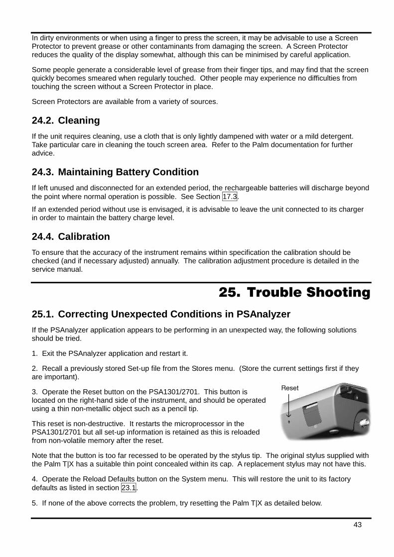
43
In dirty environments or when using a finger to press the screen, it may be advisable to use a Screen Protector to prevent grease or other contaminants from damaging the screen. A Screen Protector reduces the quality of the display somewhat, although this can be minimised by careful application.
Some people generate a considerable level of grease from their finger tips, and may find that the screen quickly becomes smeared when regularly touched. Other people may experience no difficulties from touching the screen without a Screen Protector in place.
Screen Protectors are available from a variety of sources.
24.2. Cleaning If the unit requires cleaning, use a cloth that is only lightly dampened with water or a mild detergent. Take particular care in cleaning the touch screen area. Refer to the Palm documentation for further advice.
24.3. Maintaining Battery Condition If left unused and disconnected for an extended period, the rechargeable batteries will discharge beyond the point where normal operation is possible. See Section 17.3.
If an extended period without use is envisaged, it is advisable to leave the unit connected to its charger in order to maintain the battery charge level.
24.4. Calibration To ensure that the accuracy of the instrument remains within specification the calibration should be checked (and if necessary adjusted) annually. The calibration adjustment procedure is detailed in the service manual.
25. Trouble Shooting
25.1. Correcting Unexpected Conditions in PSAnalyzer If the PSAnalyzer application appears to be performing in an unexpected way, the following solutions should be tried.
1. Exit the PSAnalyzer application and restart it.
2. Recall a previously stored Set-up file from the Stores menu. (Store the current settings first if they are important).
3. Operate the Reset button on the PSA1301/2701. This button is located on the right-hand side of the instrument, and should be operated using a thin non-metallic object such as a pencil tip.
This reset is non-destructive. It restarts the microprocessor in the PSA1301/2701 but all set-up information is retained as this is reloaded from non-volatile memory after the reset.
Note that the button is too far recessed to be operated by the stylus tip. The original stylus supplied with the Palm T|X has a suitable thin point concealed within its cap. A replacement stylus may not have this.
4. Operate the Reload Defaults button on the System menu. This will restore the unit to its factory defaults as listed in section 23.1.
5. If none of the above corrects the problem, try resetting the Palm T|X as detailed below.
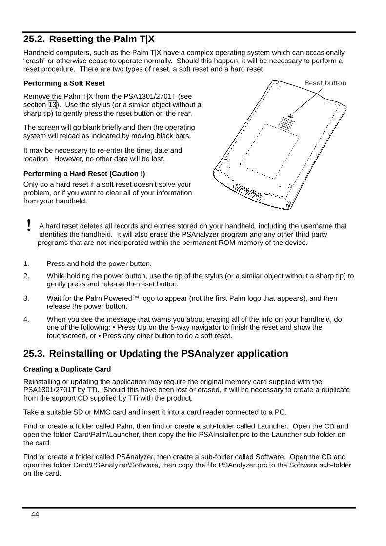
44
25.2. Resetting the Palm T|X Handheld computers, such as the Palm T|X have a complex operating system which can occasionally “crash” or otherwise cease to operate normally. Should this happen, it will be necessary to perform a reset procedure. There are two types of reset, a soft reset and a hard reset.
Performing a Soft Reset
Remove the Palm T|X from the PSA1301/2701T (see section 13). Use the stylus (or a similar object without a sharp tip) to gently press the reset button on the rear.
The screen will go blank briefly and then the operating system will reload as indicated by moving black bars.
It may be necessary to re-enter the time, date and location. However, no other data will be lost.
Performing a Hard Reset (Caution !) Only do a hard reset if a soft reset doesn’t solve your problem, or if you want to clear all of your information from your handheld.
A hard reset deletes all records and entries stored on your handheld, including the username that identifies the handheld. It will also erase the PSAnalyzer program and any other third party
programs that are not incorporated within the permanent ROM memory of the device.
1. Press and hold the power button.
2. While holding the power button, use the tip of the stylus (or a similar object without a sharp tip) to gently press and release the reset button.
3. Wait for the Palm Powered™ logo to appear (not the first Palm logo that appears), and then release the power button.
4. When you see the message that warns you about erasing all of the info on your handheld, do one of the following: • Press Up on the 5-way navigator to finish the reset and show the touchscreen, or • Press any other button to do a soft reset.
25.3. Reinstalling or Updating the PSAnalyzer application Creating a Duplicate Card Reinstalling or updating the application may require the original memory card supplied with the PSA1301/2701T by TTi. Should this have been lost or erased, it will be necessary to create a duplicate from the support CD supplied by TTi with the product.
Take a suitable SD or MMC card and insert it into a card reader connected to a PC.
Find or create a folder called Palm, then find or create a sub-folder called Launcher. Open the CD and open the folder Card\Palm\Launcher, then copy the file PSAInstaller.prc to the Launcher sub-folder on the card.
Find or create a folder called PSAnalyzer, then create a sub-folder called Software. Open the CD and open the folder Card\PSAnalyzer\Software, then copy the file PSAnalyzer.prc to the Software sub-folder on the card.
45
Reinstalling the Application Should the PSAnalyzer application be erased by performing a Hard Reset or by any other means, it will be necessary to reinstall it. The memory card supplied with the PSA1301/2701T includes a backup copy of the application and an Installer program.
Remove and re-insert the memory card supplied with the PSA1301/2701T by TTi. The Applications screen will appear showing the utility program PSAInstaller. Select this program and follow the on-screen instructions.
When completed, return to the normal Applications screen by selecting the drop down menu at the top right and select “All” in place of “Card”.
25.4. Optional Accessories Optional Accessories for the PSA1301/2701T
For a list of optional accessories for the PSA1301/2701T, visit our website: www.tti-test.com or contact TTi directly.
Optional Accessories for the Palm T|X A number of optional accessories are available for the Palm T|X, along with software applications. Palm websites are country specific, but can be accessed through the root web address: www.palm.com
25.5. Creating a Shortcut to PSAnalyzer As supplied by TTi, the PSAnalyzer application is installed within the Palm T|X applications so as to occupy the first position within the Applications screen (category All or Unfiled). Other applications (apart from Quick Tour) are listed alphabetically.
It is easy to launch PSAnalyzer from the Applications screen either by pressing the icon directly, or by using the centre button of the 5-way navigator. However, it is also possible to change the settings of the T|X so as to be able to launch PSAnalyzer from a hard key or from Favourites.
Hard Key Shortcut Open Preferences and select Buttons (under Personal). Choose a button (other than the Home button) and open the drop-down menu. Select PSAnalyzer and press Done.
Favourites Shortcut Open the favourites screen and press the top left hand tab (which displays the time). Select Rearrange Favourites. Choose a favourite on Page 1 that is of low importance, highlight it and drag it firstly to the page 2 icon and then to an unused position on that page.
Select page 1, then press and hold the newly created unused position - the Edit Favourite dialogue box will appear. Set Type: App, Original: PSAnalyzer (from drop-down), Name: PSAnalyzer. Press OK. Select and drag to the desired position on page 1. Press Done.

Thurlby Thandar Instruments Ltd. Glebe Road • Huntingdon • Cambridgeshire • PE29 7DR • England (United Kingdom)
Telephone: +44 (0)1480 412451 • Fax: +44 (0)1480 450409 International web site: www.aimtti.com • UK web site: www.aimtti.co.uk
Email: [email protected]
Aim Instruments and Thurlby Thandar Instruments Book Part No. 48511-1060 Issue 8