pss®sincal 7.5 release information - siemens energy …€¦ · · 2011-05-17n windows server...
TRANSCRIPT
Answers for energy.
PSS®SINCAL 7.5Release InformationSiemens PTI – Software Solutions
PSS®SINCAL 7.5
Page 2
General RemarksLicensing 3
Release for 64 Bit Operating Systems 3
Supporting New Database Systems 3
Documentation 4
User InterfaceBackground Maps in the Network Diagram 4
New Interface for Reports 6
Joining Lines 6
Network Element Groups in Network Brow-ser 6
Enhanced Import and Export Functions forNetwork State 7
Enhanced Network Archiving Functions 7
Other New Functions 8
Electrical NetworksLoad Flow 9
New Features for Dynamics 10
Protection 11
Optimal Network Structure 12
New Smart Load Flow 12
PSSE V33 Import and Export 13
Improvements in Performance 13
Pipe NetworksImprovements in Performance 13
Table of Contents
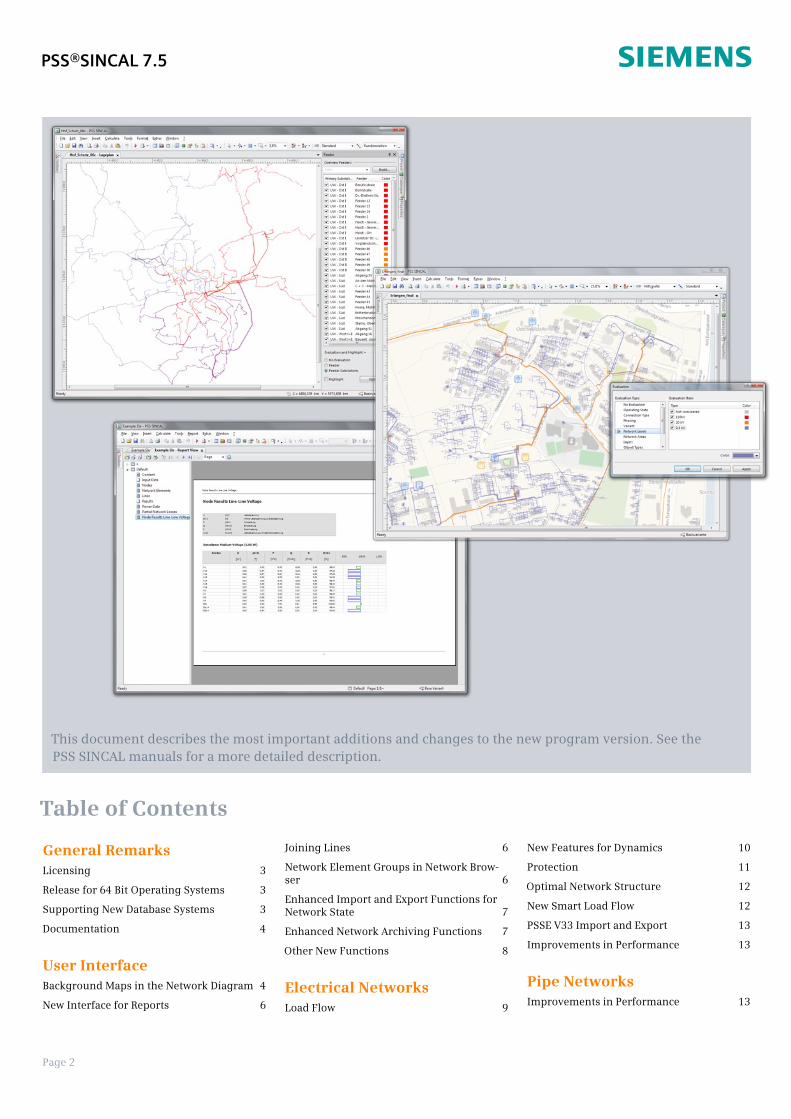
This document describes the most important additions and changes to the new program version. See thePSS SINCAL manuals for a more detailed description.

Page 3
General Remarks
Licensing
PSS SINCAL 7.5 uses the same licensefile as the preceding PSS SINCAL 7.0version. Simply copy the existing licensefile to the "Bin" directory of PSS SINCALInstallation (normally this is
"C:\Program Files\PTI\PSS SINCAL 7.5\Bin").
If you need a new license file or have anyquestions about the licensing, pleasecontact the PSS SINCAL Hotline (phone+43 699 12364435, [email protected]).
Release for 64 Bit OperatingSystems
PSS SINCAL is (currently) only availableas a 32-bit application, but it is also pos-sible to use the program trouble-free on64-bit operating systems.
The following operating systems are sup-ported:
n Windows XP (x86) Service Pack 3
n Windows Vista (x86) Service Pack 2
Windows 7 (x86 & x64)
n Windows Server 2003 (x86) ServicePack 2
Windows Server 2008 R2 (x86 &x64)
These operating systems can be usedwith all the available licensing models:PC licenses, Dongle licenses and net-work licenses. This means you can nowalso use Dongle licenses (WibuBox) on64 bit systems.
A final 64-bit version of PSS SINCAL isplanned for October 2011. It will notdiffer in its functionality from the 32-bitversion; the only difference will be thelarger addressable memory.
Supporting New DatabaseSystems
PSS SINCAL is now also enabled for usewith the current Oracle11g RDBMS. In
the way the program functions, however,nothing has changed from the preced-ing version of Oracle10g.
On the other hand, Microsoft SQL Serv-er support is, however, entirely new.This has been integrated in the productas a result of increased client demand.
The SQL Server has been integrated inthe PSS SINCAL architecture in the sameway as Oracle. The im-plementation sits di-rectly at the PSSSINCAL COM servers.The way you access da-ta priority applica-tions is absolutelytransparent; i.e. itdoes not matterwhich RDBMS deliv-ers the data.
The priority applica-tion - whether it is PSSSINCAL, PSS PDMS orPSS DB - can alwaysaccess the data insame way.
What makes SQL Server unique is that anexpress version is available free ofcharge. This can also be installed with-out any problems on a normal PC ornotebook. This is so-to-speak a "light"version of the database server. Databa-ses can be managed directly at the localcomputer without the need for a centralserver.
The solution is comparable to Access,but with the important difference thatyou have a really powerful, fully-fledgedand functional RDBMS.
The following is a list of all the relationaldatabase systems that are supported(new systems are highlighted in bold):
n Access 2003
n Access 2007
n Access 2010
n Oracle 9i
n Oracle 10g
Oracle 11g
SQL Server Express 2008
SQL Server Express 2008 R2
SQL Server 2008
SQL Server 2008 R2
New Database Configuration
The dialog box for Database Configura-
tion under Extras – Options… has beenredesigned.
The dialog box can be used to preselectthe default database system you preferto work with. If you wish, however, youcan also use different systems simulta-neously.
You can even make individual configura-tion settings for each database system.With real server systems such as Oracleor SQL Server, the database instanceand access data for managing the data-base need to be defined here. If you areusing Microsoft Access and SQL ServerExpress client databases, you can makeenhanced settings for working with thedatabases (document behavior, auto-matic compression, etc.).
New Database Management
The functions for managing databaseshave been completely reworked. Thesefunctions can be used both for updatingdatabases and for managing PSS SINCALdatabases stored on server systems.
Up until now, different dialog boxes
PSS®SINCAL 7.5
Dialog box for Database Configuration
Page 4
have been used for the various databasesystems.
Now all these functions have been inte-grated into a new central Wizard whereall administrative tasks can be done.
File – Administration – Manage Data-base… in the menu starts the Wizard formanaging databases.
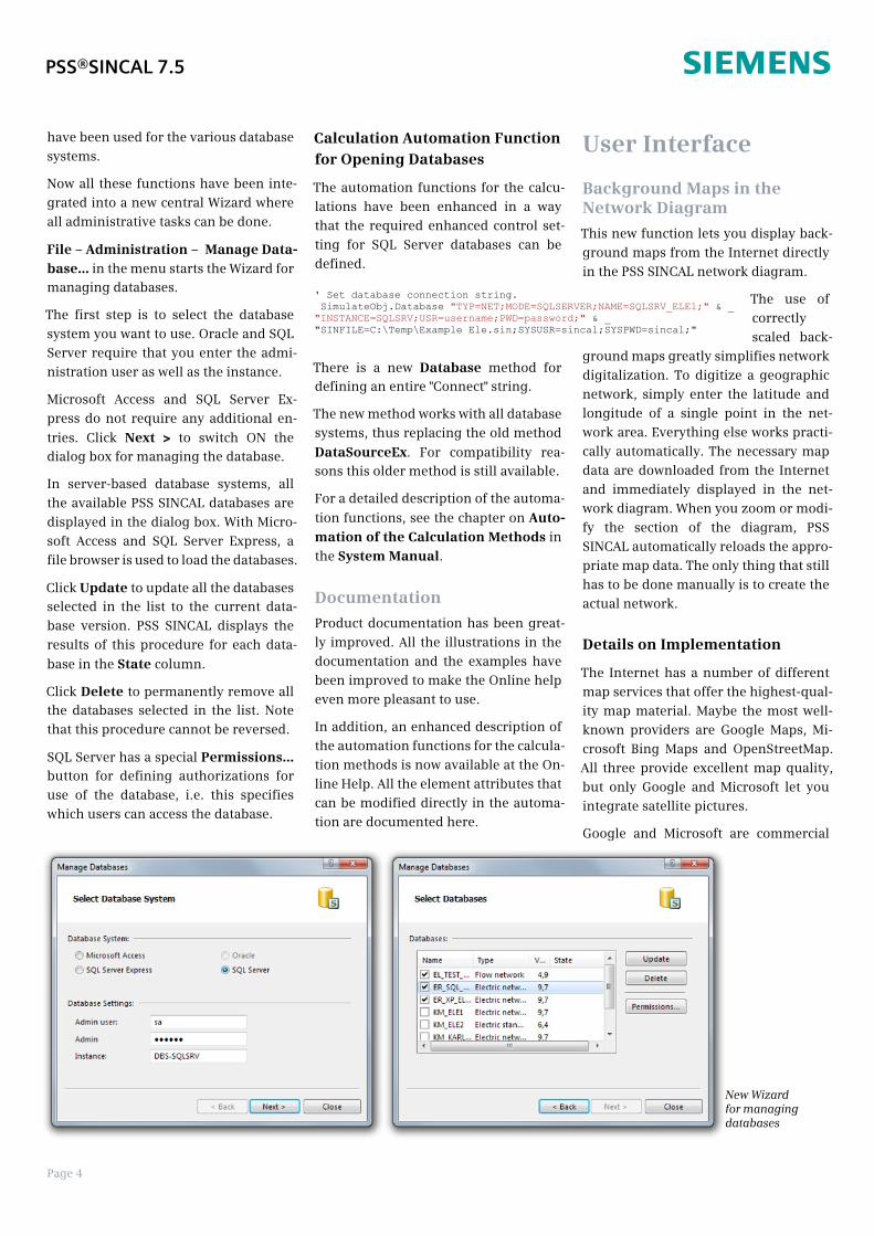
The first step is to select the databasesystem you want to use. Oracle and SQLServer require that you enter the admi-nistration user as well as the instance.
Microsoft Access and SQL Server Ex-press do not require any additional en-
tries. Click Next > to switch ON thedialog box for managing the database.
In server-based database systems, allthe available PSS SINCAL databases aredisplayed in the dialog box. With Micro-soft Access and SQL Server Express, afile browser is used to load the databases.
Click Update to update all the databasesselected in the list to the current data-base version. PSS SINCAL displays theresults of this procedure for each data-
base in the State column.
Click Delete to permanently remove allthe databases selected in the list. Notethat this procedure cannot be reversed.
SQL Server has a special Permissions…button for defining authorizations foruse of the database, i.e. this specifieswhich users can access the database.
Calculation Automation Functionfor Opening Databases
The automation functions for the calcu-lations have been enhanced in a waythat the required enhanced control set-ting for SQL Server databases can bedefined.
There is a new Database method fordefining an entire "Connect" string.
The new method works with all databasesystems, thus replacing the old method
DataSourceEx. For compatibility rea-sons this older method is still available.
For a detailed description of the automa-
tion functions, see the chapter on Auto-mation of the Calculation Methods in
the System Manual.
Documentation
Product documentation has been great-ly improved. All the illustrations in thedocumentation and the examples havebeen improved to make the Online helpeven more pleasant to use.
In addition, an enhanced description ofthe automation functions for the calcula-tion methods is now available at the On-line Help. All the element attributes thatcan be modified directly in the automa-tion are documented here.
User Interface
Background Maps in theNetwork Diagram
This new function lets you display back-ground maps from the Internet directlyin the PSS SINCAL network diagram.
The use ofcorrectlyscaled back-
ground maps greatly simplifies networkdigitalization. To digitize a geographicnetwork, simply enter the latitude andlongitude of a single point in the net-work area. Everything else works practi-cally automatically. The necessary mapdata are downloaded from the Internetand immediately displayed in the net-work diagram. When you zoom or modi-fy the section of the diagram, PSSSINCAL automatically reloads the appro-priate map data. The only thing that stillhas to be done manually is to create theactual network.
Details on Implementation
The Internet has a number of differentmap services that offer the highest-qual-ity map material. Maybe the most well-known providers are Google Maps, Mi-crosoft Bing Maps and OpenStreetMap.All three provide excellent map quality,but only Google and Microsoft let youintegrate satellite pictures.
Google and Microsoft are commercial
New Wizardfor managingdatabases
' Set database connection string.SimulateObj.Database "TYP=NET;MODE=SQLSERVER;NAME=SQLSRV_ELE1;" & _
"INSTANCE=SQLSRV;USR=username;PWD=password;" & _"SINFILE=C:\Temp\Example Ele.sin;SYSUSR=sincal;SYSPWD=sincal;"
PSS®SINCAL 7.5

Page 5
providers; i.e. the use of the map materi-al in applications is subject to very re-strictive licensing regulations and is notfree of charge. Only accessing the datawith the Web browser is free. To use thedata in applications, each end userneeds to have its own license and, de-pending on license model, charges thenaccrue each time you use the map data.
OpenStreetMap is free project that col-lects geographical data and is free foranyone to use. The heart of the project isa database similar to wiki that has geo-graphic data. These data may be usedaccording to the Creative-Commons-At-tribution-ShareAlike-2.0 license. This al-lows you to use the data in printouts,Webpages, and applications such as nav-igation software, all without being limit-ed by restrictive licenses or having to pay.
The provider CloudMade(http://cloudmade.com) has been usedin PSS SINCAL to incorporate the back-ground maps. This service lets youdownload map material based on Open-StreetMap for applications.
Background maps are made up of pre-rendered tiles. These tiles are squarebitmaps of uniform size (256 x 256 pi-xels) available in 18 predefined levels ofdetail for the entire Earth. The lowestlevel of detail describes the whole planet
with only one tile. For the highest levelof detail, approx. 70 billion tiles are ne-cessary.
Use of Background Maps
General preliminary settings for usingbackground maps can be set in the op-
tions (Extras – Options…) dialog box.
PSS SINCAL automatically presets thelink to the CloudMade server and makesany required connection settings.
If you wish, you can change the directo-ry used for saving the downloaded tiles.This directory stores all the downloadedtiles. Local temporary storage bothgreatly speeds up how the backgroundmap is displayed, and, as soon as allrequired tiles have been downloaded,the background maps can be used en-tirely without being connected to theInternet.
To use a backgroundmap in a new net-work, only a fewsteps are required.First, you need a geo-graphic network.
File – New… in themenu opens the dia-log box for creatingthe new network. Inthe following exam-ple, a new geogra-phic network is crea-ted with an area of 40x 30 km.
In the next step, you
can use Tools –
Background Map…
in the menu to place the map. In thedialog box, simply assign a latitude andlongitude to any point in the networkarea. In this example, the center of Vien-na has been used as the middle of thenetwork area.
Click Open position in Google Maps tocheck the map position currently set.This opens the Web browser and dis-plays the latitude and longitude previ-ously set in GoogleMaps.
Display configures how the backgroundmap will be displayed. You can evenselect map display intensity and thegraphics layer.
Preload allows you to automaticallydownload tiles for selected zoom stepsin the background. In this way, all thetiles for the network area can be down-loaded from the Internet and stored lo-cally in advance. If you do not preload,the tiles are loaded as soon as they arerequired.
Click OK to close the dialog box and PSSSINCAL displays the background map inthe network diagram.
PSS®SINCAL 7.5
Background map of London in PSS SINCAL
Options for Background Maps
Defining the area size for the new network
Placing the background map
Page 6
New Interface for Reports
PSS SINCAL has a flexible report-genera-tion system based on Crystal Reports 11.There are a number of predefined re-ports for both electricity and pipe net-works to help you visualize input andoutput data.
To improve the way you work with thereports and make this procedure evenmore user-friendly, reports are attachedin an application window the same wayas the Tabular View and Diagram View.
This new integration fundamentally im-proves how working with reports is inte-grated into the work cycle. The reportwindow is opened as needed. You can,however, change to another applicationwindow at any time without having toclose reports.
The new report window can either be
opened by using View – Report View inthe menu, with a new icon in the stan-dard toolbar or by pressing the "F11" key.
The report window has two parts. On theleft, there is a Tree-Control sectionwhere compilations can be opened.These can be made up of any collectionof individual reports you want to look at,export or print out. The actual report isdisplayed on the right. Crystal Reports'Render-Engine is used to display thereport.
There are functions for editing the com-pilation and, of course, also those need-ed for controlling the generalappearance of the reports in the toolbar
and in the Report menu.
For a detailed description of these newreporting functions, see the chapter on
Reports in the System Manual.
Joining Lines
This function joins lines selected in theGraphics Editor. The prerequisite forthis is that the lines can be connectedfrom a technical standpoint: i.e. thatthey need to be in the same networklevel, have the same conductors, etc. Inaddition, the lines cannot have any
"branches".
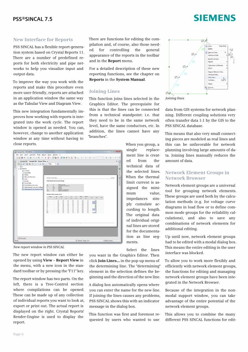
When you group, asingle replace-ment line is creat-ed from thetechnical data ofthe selected lines.When the thermallimit current is as-signed the mini-mum value,impedances sim-ply cumulate ac-cording to length.The original dataof individual origi-nal lines are storedfor the documenta-tion as line seg-ments.
Select the linesyou want in the Graphics Editor. Then
click Join Lines… in the pop-up menu ofthe determining line. The "determining"element in the selection defines the be-ginning and the direction of the new line.
A dialog box automatically opens whereyou can enter the name for the new line.If joining the lines causes any problems,PSS SINCAL shows this with an indicatormessage in the dialog box.
This function was first and foremost re-quested by users who wanted to use
data from GIS systems for network plan-ning. Different coupling solutions veryoften transfer data 1:1 by the GIS to thePSS SINCAL database.
This means that also very small connect-ing pieces are modeled as real lines andthis can be unfavorable for networkplanning involving large amounts of da-ta. Joining lines manually reduces theamount of data.
Network Element Groups inNetwork Browser
Network element groups are a universaltool for grouping network elements.These groups are used both by the calcu-lation methods (e.g. for voltage curvediagrams in load flow or to define com-mon mode groups for the reliability cal-culations), and also to save anycombinations of network elements foradditional editing.
Up until now, network element groupshad to be edited with a modal dialog box.This means the entire editing in the userinterface was blocked.
To allow you to work more flexibly andefficiently with network element groups,the functions for editing and managingnetwork element groups have been inte-grated in the Network Browser.
Because of the integration in the non-modal support window, you can takeadvantage of the entire potential of thenetwork element groups.
This allows you to combine the manydifferent PSS SINCAL functions for edit-
PSS®SINCAL 7.5
New report window in PSS SINCAL
Joining lines

Page 7
ing and evaluating networks with theevaluation and selection functions fornetwork element groups any way youwant.
The new evaluation function for networkelement groups is also especially practi-cal. Network elements are colored ac-cording to the group they belong to.
When the amount to be displayed in thedialog box changes (e.g. with the filterfield), PSS SINCAL immediately displaysthese changes in the network diagram.
Enhanced Import and ExportFunctions for Network State
These let you export PSS SINCAL net-work states (i.e. the switch state, opera-ting state and controller data of networkelements) to a file, so you can save diffe-rent network states and import themagain later.
This functionexports net-work states(i.e. theswitch posi-tions, opera-ting statesand control-ler data ofnetwork ele-ments) intoa file, so youcan save ope-rating statesfor a net-work and im-port theseagain later.
To furtherimprove theflexibility ofthis function,it has beencomprehen-sive en-hanced. Nowpracticallyall the impor-
tant attributes of the network elementscan be imported or exported.
Exporting a Network State
The Wizard for exporting the network
state can be started with the help of File– Export – Network State… in the menu.
Select the XML file where the networkstate is to be stored on the first dialogpage of the Wizard. The export scopecan also be defined.
There is a new Element data option. Ifthis is switched ON, PSS SINCAL displaysa second dialog page where you can se-lect the attributes of the network ele-ments to be stored in the XML file.
So that the settings do not have to bedefined again each time you export,they can be stored in a compilation file.
Importing a Stored NetworkState
To import a stored network state, click
File – Import – Network State… in themenu. Simply select the XML file in theWizard from where the data should beloaded.
Enhanced Network ArchivingFunctions
Network archiving functions in PSS SIN-CAL are a practical tool for saving net-works with all data to a ZIP archive. Thenetwork archive is, of course, a normalZIP archive, but with a special structure.
To be sure that these cannot be confusedwith normal ZIP archives when you im-port them, network archives are storedwith the new ".sinx" extension (analo-gous to Microsoft Word documents
"docx").
The data in the archive can either bestored in the original format (.mdb,
.mdf) or in a database-independent XMLformat. The data-base-independentXML format is pri-marily intended forserver databasessuch as ORACLE andMicrosoft SQL Server,making it easier tosave or export all thenetwork data.
To improve the ar-chiving functions
even further, there is a possibility ofeither storing local and global standardtype databases, local and global protec-tion device databases and local and glo-
PSS®SINCAL 7.5
Network Element Group and Graphic Element Group in the Network Browser
Export Network State Wizard

Page 8
bal models in the network archive.
This lets you archive a network with allthe supplementary data comfortably inone step. This is particularly practical ifyou want to forward all the data for ana-lysis or editing.
Exporting Network Data
The actual archiving is done with a Wi-
zard started with File – Export – Net-work Archive… in the menu.
On the first dialog page, select only thearchive file and the storage format forthe data.
The second dialog page is used for set-ting parameters as to whether databasesand models assigned to the networkshould also be saved to the archive.
Importing the Network Data
To import data from an existing networkarchive, first create a new network. Thenext step is particularly important: youneed to save the network. This deter-mines the storage location in the filesystem needed to import the assignedstandard type databases and models.
When you have done this, start the im-
port function File – Import – NetworkArchive… in the menu. This opens an-other Wizard where you can select thearchive to be imported.
Other New Functions
This section is a short overview of thedifferent new features improving exis-ting functions.
Improved Standard Type DialogBoxes
PSS SINCAL has special dialog boxes for
editing standard types (Insert – Stan-dard Type). These dialog boxes consistof a Tree-Control section where all theavailable types are organized hierarchi-cally (tree view) and a data screen formwith the actual data of the Standard Type.
To improve how standard types are se-lected and located, a new quick-filter
function has been in-tegrated into the dia-log boxes. This isavailable in the tool-bar above Tree-Con-trol. Typingsomething in the fil-ter field immediate-ly updates thedisplay in Tree-Con-trol. This makes it
easier to locate a specific type - evenwhen there are thousands of types (e.g.as with lines).
Enhanced Symbols for DC-Infeed-ers
DC-infeeders have new graphic symbols.PSS SINCAL automatically displays thenew symbols in the network diagramwith the help of the selected infeedertype.
If you want to use another symbol, you
can select this with the Format dialogbox.
Enhanced Toolbar Collections
This function for switching toolbar col-
lections in the View – Toolbar Collec-tion menu or at the corresponding
symbol in the Standard toolbar lets youchoose between 5 different collections.
The current visibility of all the toolbarsand support windows is stored in thetoolbar collection. Simply select thepoint in the menu or use the key abbrevi-ation to switch between collections. Thisdisplays the required user interface ele-ments for the current work situation onthe screen.
Improved Connection of Dia-grams and Tables
The way diagrams and tables are con-nected has been improved. A toolbarwith the important functions has beenintegrated into both application win-dows. This means the important re-quired functions are directly available inthe application window and you do nothave to waste time switching betweentoolbars in the main window.
Simplified Sending of Error Re-ports
Sending error reports to PSS SINCALSupport has been organized in a moreuser-friendly way.
? – Bug Report opens a simple form inthe menu where you can enter contactinformation and a description of theproblem.
Simply click Send to send these datadirectly via the Internet to PSS SINCALSupport.
New Features for Station Models
Based on the requests of various usersthere is a new function for deleting un-used bays (i.e. those without any equip-ment or network elements). The newfunction is attached to the Station Brow-ser. There is an enhanced pop-up menu
PSS®SINCAL 7.5
Network Archive Export Wizard
Dropdown menu for selecting the toolbarcollection

Page 9
for deleting unused bays at a station (orat all the stations).
There is also a new station find function.The PSS SINCAL dialog box used tosearch for network elements has beenenhanced so that it can search for sta-tions as well.
Improved Way to Include Owners
The pop-up menu of the network ele-ments can now also be used to edit ele-ment owners.
This opens a new dialog box that clearlyrepresents all assigned owners. In thisdialog box, you can assign owners orremove it at any time.
New Example of Automation
PSS SINCAL has a new VBS script to dis-play the enhanced functions for calcula-tion automation. In the example, thesimulation method for ContingencyAnalysis is used at different times to find
any future weak points inthe network.
The new example of automa-tion is available in the PSSSINCAL installation struc-ture:
"Project\Batch\Advanced\SimMethodsOverTime.vbs"
Network Tools Toolbar
The toolbar for editing themost important topologystructures of the network
was enhanced. In addition to the comboboxes for network levels and networkareas three new drop-down menus areavailable, enabling an easy access to fre-quently used data.
Network element groups, graphic ele-ment groups and network zones can beedited in the first drop down menu.
With the second drop down menu youcan edit the most important additionaldata. These include main busbars, brea-kers, owners, generic data, descriptions,global settings and currencies.
Extended data, such as coupled lines,neutral point impedances, compensa-tion impedances, measure data, etc. canbe edited with the third drop down menu.
Modified Shortcut Keys and NewPopup Menus
PSS SINCAL's keyboard shortcuts havebeen reworked and enhanced.
For an itemized list of all the standard
shortcut keys, see the Shortcuts section
in the chapter on Technical Referencein the System Manual.
Shortcut keys can, of course, be custo-
mized to meet individual needs with thehelp of the Options dialog box.
Some new popup menus can also becalled up with shortcut keys. Particular-ly useful are
n the Topology menu(access to topology objects such asnetwork level, network area ...),
n the Additional Element Data menu(data for the selected network ele-ment),
n the Reliability menu(enhanced data for reliability) andfinally
n the Dynamics menu(enhanced data for dynamics).
Electrical Networks
Load Flow
PSS®E Load Flow in PSS SINCAL
PSS SINCAL lets you start PSSE LoadFlow directly in the user interface.
The prerequisite for this is that PSSE V32or PSSE V33 has been installed on thecomputer. If this is the case, PSS SINCALhas a new menu item for starting PSSELoad Flow.
The results of the PSSE load flow arefundamentally different in content fromthose in PSS SINCAL: Node voltages andangles are entered in the input data, allvalues are per unit, etc.
So that PSSE load flow results can beused directly in PSS SINCAL, the follo-wing is done: After the calculations, theinternal results are transferred fromPSSE to the PSS SINCAL calculationmethods. A special mapping has to beperformed, since PSSE uses internalkeys for the calculations.
Once the mapping is finished, the re-sults can be processed further with thePSS SINCAL calculation methods. At thispoint, all the additional load flow resultsare calculated from the supplied calcula-tion results. Then the results preparedby PSS SINCAL are stored in the data-
PSS®SINCAL 7.5
Pop-up menu for deleting unused bays
Pop-up menu for the selected network element
Network tools toolbar

Page 10
base. This assures that the different LFresults tables in the network databasehave been filled correctly.
If the load flow calculations were suc-cessful, then you get the same resultsscope as with PSS SINCAL load flow.
This means that the results can be dis-played in the network diagram, evalua-ted in screen forms and tables, and pro-vided in reports.
The sequence log of the PSSE load flowcalculations is provided in the PSS SIN-CAL message box (log file).
Power Control at Transformers
Power control for transformers has beenenhanced. Up until now, PSS SINCALcould only make control at a predefinedtarget value. Now a power band (i.e.with upper and lower limits) can be de-fined for control.
Discrete or Continuous Control
PSS SINCAL lets you determine the con-troller positions either discretely or con-
tinuously. The Controller Adjustmentfield is used to select the type of resultsin the basic data of the calculation set-tings.
Remote Control at the Static Com-pensator (SVC)
The voltage at the connection node hasalways been used to calculate the cur-rent reactive power of the SVC.
In modern networks, however, SVCs canmonitor the voltage at a node that is faraway. Now this function also exists in
PSS SINCAL. Simply select a ControllerNode for which the voltage is to be regu-
lated in the Basic Data tab.
Improved Controller Data Inputfor Infeeders
The way controller data and limits areentered for network elements for syn-chronous machines, power units, andinfeeders has been redesigned.
The technical limits for operating beha-vior are now clearly separate from thecontroller data.
New Features for Dynamics
One-Phase Machines
At one-phase machines, the equivalentconnection of the one-phase machinesimulates the rotor data. This is trueboth for one-phase asynchronous andone-phase synchronous machines.
For one-phase asynchronous ma-chines, note the following:Equivalent model data are used to simu-late one-phase asynchronous machines.This is true both for machines betweenphase and ground and machines be-tween two phases.
For one-phase synchronous ma-chines, note the following:Winding data are used to simulate one-phase machines. This is true both formachines between phase and groundand machines between two phases.
The armature leakage reactance needsto already contain the influence of theinverse field.
The direct axis needs to have the resis-tance damper winding, the leakage reac-tance damper winding, the resistancefield winding, the leakage reactancefield winding and the magnetizing reac-tance.
The quadrature axis needs to have theresistance damper winding, theleakage reactance damper wind-ing and the magnetizing reac-tance.
Residual Voltage (Flux)for Saturations
For more precise observationsof the starting operation, youneed to enter the residual volt-age (flux) per phase. This infor-mation has been added to thedynamics data for the followingnetwork elements:
n Two-winding transformer
n Three-winding transformer
n Current transformer
n Shunt reactor
n Shunt impedance
n Serial reactor
n Load
Additional Feature Zero-PhaseSequence/Grounding
PSS NETOMAC simulates asymmetricalnetwork elements as individual bran-ches both in the phases and the returnline. The network elements' zero-phasesequence impedance is used to deter-mine the neutral point connection to thereturn line.
As experience from different projectshas shown, the zero-phase sequence im-pedance of the network elements is notknown in asymmetrical medium-vol-tage networks. When you use standardvalues for the zero-phase sequence dataor enter values similar to the positive-
PSS®SINCAL 7.5
PSSE Load Flow in PSS SINCAL
Input data for the synchronous machine

Page 11
phase sequence, the calculations forneutral-point impedance produce nega-tive values and problems in the dynam-ics. The same problem exists whenpositive-phase sequence data are cor-rected without updating the zero-phasesequence data.
The input of zero-phase sequence datanow includes the possibility of selecting
"Z0 identical Z", so you can enter a neu-tral-point impedance for the followingnetwork elements:
n Synchronous machine
n Asynchronous machine
n Infeeder
n Load
n Variable shunt element
n Shunt impedance
n Shunt reactor
Enhanced Variables forDynamics
The models for the dynamic calculationspermit the use of variables. This meansboth that the behavior of the model canbe controlled and that topological refe-rences can be defined.
To edit the variables for dynamics, select
Insert – Dynamics – Variables for Dy-namics… in the menu to open a specialdialog box.
For the topology variable types for nodeand element, this dialog box has an en-try for Phase (L1, L2, L3, L12, L23, L31,L123). This additional information isneeded to simulate asymmetrical net-works.
Protection
Universal Protection De-vices
Modern protection deviceshave various functions fortripping. Up until now, PSSSINCAL needed to have diffe-rent protection devices at aterminal to simulate a protec-tion device with different trip-ping characteristics. Thismade entering data compli-cated, and identical datasometimes needed to be en-tered more than once.
To solve this problem, how protectiondevices and their settings are managedand processed internally has been en-hanced. Now a location can have asmany settings for tripping characteris-tics as you want. Even combinations ofOC, DI and DIFF settings are possible.
The protection device dialog box showsa device with several different settings.
In the Protection Device dialog box, thepop-up Tree-Control menu lets you addnew settings for tripping at any time.
The functions for protection device an-notation have also been improved. Atdevices with multiple settings (OC, DI,DIFF), these are displayed block by blockone after another.
Preliminary Setting for Short Cir-cuit Procedure
In network planning, the short circuitcalculation settings are usually set forsystem planning (maximum). This set-ting, however, cannot be used to checkprotection pickup. Protection pickuphas to work properly even with currentnetwork conditions and when there areminimum short circuit powers at the in-feeder.
The calculation settings for protectioncoordination now also have entries for
Short Circuit Method and Short Cir-cuit Data Type. This means the short
circuit method can be preset directly forprotection coordination.
Considering Differential Protec-tion Devices
Up until now, PSS SINCAL only useddifferential protection devices for reli-ability calculations. These protection de-vices are now also included inprotection coordination and when ge-nerating protection routes.
The consideration is done according tothe following simplified principle. It isnot necessary to have a sum of current.The fault location alone determineswhether the differential protection de-vices of the protection zone will trip.Elements of the protection zone are de-termined with the help of their own net-work tracing - depending on node orelement differential protection.
The tripping time is different for eachdifferential protection device indicated.If the tripping times for differential pro-tection devices in a protection zone arenot identical, tripping for all of them isdone at the smallest indicated time. Atthe moment, the differential protectiondevices are only assigned a single trip-ping time as a setting.
The following agreements are valid forconsidering the differential protectiondevices in the calculation methods:
Differential protection for nodes: Ifall the differential protection devices of
PSS®SINCAL 7.5
Dialog box for editing variables for dynamics
New Protection Device dialog box
Page 12
a protection zone indicate the same in-sert node, the protection direction isbackward.
Differential protection for elementsor element groups: If differential pro-tection devices of a protection zone havedifferent insert nodes, the protectiondirection is forward.
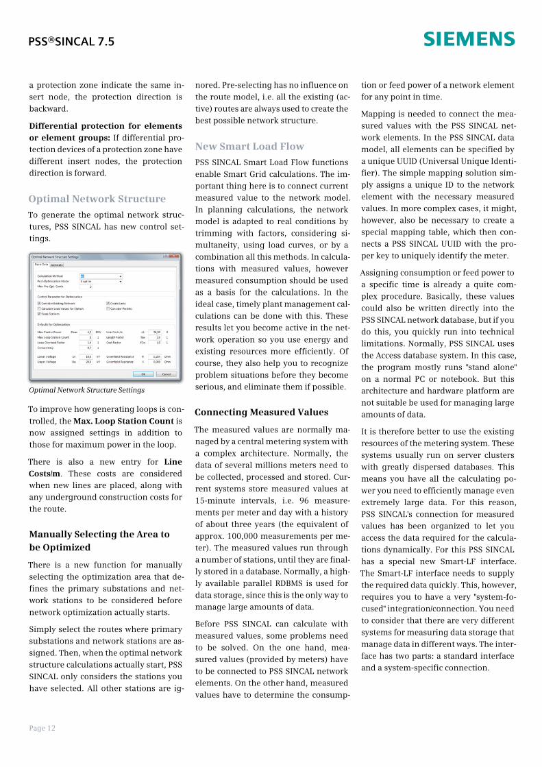
Optimal Network Structure
To generate the optimal network struc-tures, PSS SINCAL has new control set-tings.
To improve how generating loops is con-
trolled, the Max. Loop Station Count isnow assigned settings in addition tothose for maximum power in the loop.
There is also a new entry for LineCosts/m. These costs are consideredwhen new lines are placed, along withany underground construction costs forthe route.
Manually Selecting the Area tobe Optimized
There is a new function for manuallyselecting the optimization area that de-fines the primary substations and net-work stations to be considered beforenetwork optimization actually starts.
Simply select the routes where primarysubstations and network stations are as-signed. Then, when the optimal networkstructure calculations actually start, PSSSINCAL only considers the stations youhave selected. All other stations are ig-
nored. Pre-selecting has no influence onthe route model, i.e. all the existing (ac-tive) routes are always used to create thebest possible network structure.
New Smart Load Flow
PSS SINCAL Smart Load Flow functionsenable Smart Grid calculations. The im-portant thing here is to connect currentmeasured value to the network model.In planning calculations, the networkmodel is adapted to real conditions bytrimming with factors, considering si-multaneity, using load curves, or by acombination all this methods. In calcula-tions with measured values, howevermeasured consumption should be usedas a basis for the calculations. In theideal case, timely plant management cal-culations can be done with this. Theseresults let you become active in the net-work operation so you use energy andexisting resources more efficiently. Ofcourse, they also help you to recognizeproblem situations before they becomeserious, and eliminate them if possible.
Connecting Measured Values
The measured values are normally ma-naged by a central metering system witha complex architecture. Normally, thedata of several millions meters need tobe collected, processed and stored. Cur-rent systems store measured values at15-minute intervals, i.e. 96 measure-ments per meter and day with a historyof about three years (the equivalent ofapprox. 100,000 measurements per me-ter). The measured values run througha number of stations, until they are final-ly stored in a database. Normally, a high-ly available parallel RDBMS is used fordata storage, since this is the only way tomanage large amounts of data.
Before PSS SINCAL can calculate withmeasured values, some problems needto be solved. On the one hand, mea-sured values (provided by meters) haveto be connected to PSS SINCAL networkelements. On the other hand, measuredvalues have to determine the consump-
tion or feed power of a network elementfor any point in time.
Mapping is needed to connect the mea-sured values with the PSS SINCAL net-work elements. In the PSS SINCAL datamodel, all elements can be specified bya unique UUID (Universal Unique Identi-fier). The simple mapping solution sim-ply assigns a unique ID to the networkelement with the necessary measuredvalues. In more complex cases, it might,however, also be necessary to create aspecial mapping table, which then con-nects a PSS SINCAL UUID with the pro-per key to uniquely identify the meter.
Assigning consumption or feed power toa specific time is already a quite com-plex procedure. Basically, these valuescould also be written directly into thePSS SINCAL network database, but if youdo this, you quickly run into technicallimitations. Normally, PSS SINCAL usesthe Access database system. In this case,the program mostly runs "stand alone"on a normal PC or notebook. But thisarchitecture and hardware platform arenot suitable be used for managing largeamounts of data.
It is therefore better to use the existingresources of the metering system. Thesesystems usually run on server clusterswith greatly dispersed databases. Thismeans you have all the calculating po-wer you need to efficiently manage evenextremely large data. For this reason,PSS SINCAL's connection for measuredvalues has been organized to let youaccess the data required for the calcula-tions dynamically. For this PSS SINCALhas a special new Smart-LF interface.The Smart-LF interface needs to supplythe required data quickly. This, however,requires you to have a very "system-fo-cused" integration/connection. You needto consider that there are very differentsystems for measuring data storage thatmanage data in different ways. The inter-face has two parts: a standard interfaceand a system-specific connection.
PSS®SINCAL 7.5
Optimal Network Structure Settings
Page 13
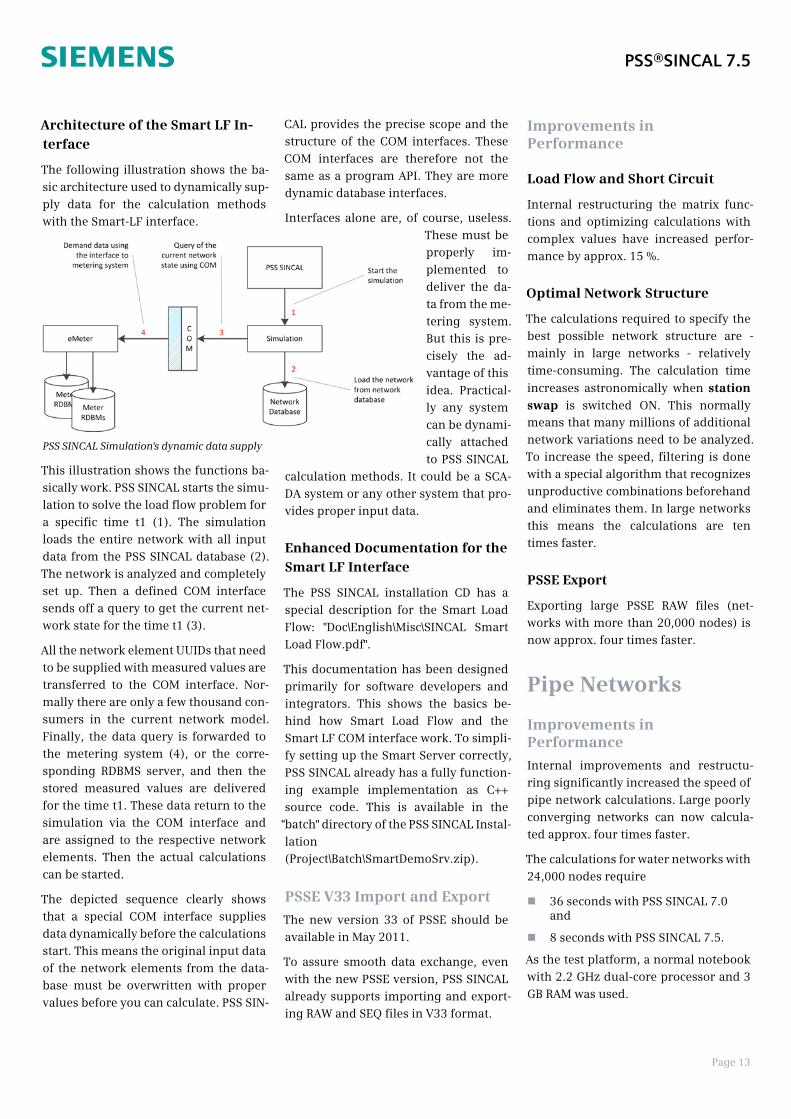
Architecture of the Smart LF In-terface
The following illustration shows the ba-sic architecture used to dynamically sup-ply data for the calculation methodswith the Smart-LF interface.
This illustration shows the functions ba-sically work. PSS SINCAL starts the simu-lation to solve the load flow problem fora specific time t1 (1). The simulationloads the entire network with all inputdata from the PSS SINCAL database (2).The network is analyzed and completelyset up. Then a defined COM interfacesends off a query to get the current net-work state for the time t1 (3).
All the network element UUIDs that needto be supplied with measured values aretransferred to the COM interface. Nor-mally there are only a few thousand con-sumers in the current network model.Finally, the data query is forwarded tothe metering system (4), or the corre-sponding RDBMS server, and then thestored measured values are deliveredfor the time t1. These data return to thesimulation via the COM interface andare assigned to the respective networkelements. Then the actual calculationscan be started.
The depicted sequence clearly showsthat a special COM interface suppliesdata dynamically before the calculationsstart. This means the original input dataof the network elements from the data-base must be overwritten with propervalues before you can calculate. PSS SIN-
CAL provides the precise scope and thestructure of the COM interfaces. TheseCOM interfaces are therefore not thesame as a program API. They are moredynamic database interfaces.
Interfaces alone are, of course, useless.These must beproperly im-plemented todeliver the da-ta from the me-tering system.But this is pre-cisely the ad-vantage of thisidea. Practical-ly any systemcan be dynami-cally attachedto PSS SINCAL
calculation methods. It could be a SCA-DA system or any other system that pro-vides proper input data.
Enhanced Documentation for theSmart LF Interface
The PSS SINCAL installation CD has aspecial description for the Smart LoadFlow: "Doc\English\Misc\SINCAL SmartLoad Flow.pdf".
This documentation has been designedprimarily for software developers andintegrators. This shows the basics be-hind how Smart Load Flow and theSmart LF COM interface work. To simpli-fy setting up the Smart Server correctly,PSS SINCAL already has a fully function-ing example implementation as C++source code. This is available in the
"batch" directory of the PSS SINCAL Instal-lation(Project\Batch\SmartDemoSrv.zip).
PSSE V33 Import and Export
The new version 33 of PSSE should beavailable in May 2011.
To assure smooth data exchange, evenwith the new PSSE version, PSS SINCALalready supports importing and export-ing RAW and SEQ files in V33 format.
Improvements inPerformance
Load Flow and Short Circuit
Internal restructuring the matrix func-tions and optimizing calculations withcomplex values have increased perfor-mance by approx. 15 %.
Optimal Network Structure
The calculations required to specify thebest possible network structure are -mainly in large networks - relativelytime-consuming. The calculation time
increases astronomically when stationswap is switched ON. This normallymeans that many millions of additionalnetwork variations need to be analyzed.To increase the speed, filtering is donewith a special algorithm that recognizesunproductive combinations beforehandand eliminates them. In large networksthis means the calculations are tentimes faster.
PSSE Export
Exporting large PSSE RAW files (net-works with more than 20,000 nodes) isnow approx. four times faster.
Pipe Networks
Improvements inPerformance
Internal improvements and restructu-ring significantly increased the speed ofpipe network calculations. Large poorlyconverging networks can now calcula-ted approx. four times faster.
The calculations for water networks with24,000 nodes require
n 36 seconds with PSS SINCAL 7.0and
n 8 seconds with PSS SINCAL 7.5.
As the test platform, a normal notebookwith 2.2 GHz dual-core processor and 3GB RAM was used.
PSS®SINCAL 7.5
PSS SINCAL Simulation's dynamic data supply

www.siemens.com/energy/power-technologies/software
Published by and copyright © 2011:Siemens AGEnergy SectorFreyeslebenstrasse 191058 Erlangen, Germany
Siemens AGEnergy SectorPower Distribution DivisionTransmission and Distribution ServicesPower Technologies InternationalFreyeslebenstrasse 191058 Erlangen, Germany
For more information, please contactour Customer Support Center.Phone: +49 180 524 70 00Fax: +49 180 524 24 71(Charges depending on provider)E-mail: [email protected]
All rights reserved.Trademarks mentioned in this documentare the property of Siemens AG, its affiliates,or their respective owners.
Subject to change without prior notice.The information in this document containsgeneral descriptions of the technical optionsavailable, which may not apply in all cases.The required technical options should thereforebe specified in the contract.