psw-d112/dps-12 - atw.huusers.atw.hu/bazsielektron/hang box/jbl psw-d112-dps-12.pdf ·...
TRANSCRIPT

JBL Consumer Products Inc.250 Crossways Park DriveWoodbury, N.Y. 117971-800-336-4JBL in the USA
A Harman International Company
Rev G 8/2004
PSW-D112/DPS-12Powered Subwoofer
SERVICE MANUAL
SAFETY INFORMATION
Warning
Caution
Leakage/Resistance Check
List of Safety Components RequiringExact Replacements(all parts POWER AMP PCB except TR2)
C6 (Rev0) 4.7uf 100V 80/-20% Electrolytic redial NPC6 (Rev1) 4.7uf 100V 80/-20% Electrolytic redial NPTR2 MPS A13 30V NPN(Darl)
R4a/b/c 0.1 0.5W 5% metal film
R9 3.3 5W 5% ceramic wirewound
R15 100k 0.5W 5% carbon film
DBR Bridge Rect 200V Use only factory replacement.R1 10M 0.25W 5% carbon film
R16, 17 1.8k 5W 5% ceramic wirewound
R33 (Rev0) only) 332 0.5W 5% carbon film
R50 (Rev0) only) 332 0.5W 5% carbon film
R52, 57 2.7k 5W 5% ceramic wirewound
R61 3.9k 3W 5% carbon film
S64AMI Power output module. Use only factoryreplacement
Faceplate Faceplate. Use only factory replacementCMC1 Use only factory replacement
L1 Use only factory replacement
Fuse PCB Use only factory replacement
Main PCB Use only factory replacement
4700uF,50V electrolytic filter caps. Be surereplacement part is at least the sameworking voltage and capacitance rating.Also the lead spacing is important.Incorrect spacing may cause prematurefailure due to internal cabinet pressure andvibration.
2
Amplifier/Subwoofer
F1
PWRCORD
TRX1
C1, 2
Transformer. Use only factory replacement.
SPT-2 or better with polarized plug, ULapproved wire with the hot side to fusedside. Use with factory replacement panelstrain relief only.
Fuse SLO BLO 1.25A 250V UL approved
Any person performing service of this unit will be exposed to hazardous voltages and the risk of electric shock. It is assumed that any person who removes the amplifier from this cabinet has been properly trained in protecting against avoidable injury and shock. Therefore, any service procedures are to be performed by qualified service personal ONLY!
Before returning the unit to the customer, perform a leakage or resistance test as follows:
Leakage Current. Note there is no power switch on this unit. When the power plug is plugged in, the unit is live. Connect the unit to its rated power source. Using an ammeter, measure the current between the neutral side of the AC supply and chassis ground of the unit under test. If leakage current exceeds 0.5A, the unit is defective. Reverse the polarity of the AC supply and repeat.
Resistance. Measure the resistance from either side of the line cord to chassis ground. If it is less than 500k ohms, the unit is defective.
WARNING! DO NOT return the unit to the customer if it fails one of these tests until the problem is located and corrected.
This unit does not have a power switch. Hazardous voltages are present within the unit whenever it is plugged in.
Before the amplifier is plugged in, be sure its rated voltage corresponds to the voltage of the AC power source to be used. Incorrect voltage could cause damage to the amplifier when the AC power cord is plugged in. Do not exceed rated voltage by more than 10%: operation below 90% of rated voltage will cause poor performance or may shut the unit off.
0046
5-2
IMPORTANT SERVICE NOTES: When testing the PSW-D112/DPS-12 Series amplifier, a load must always beconnected to the output terminals, whether the woofer, or a 4 to 8 ohm resistive load.All AC powered test instruments (meters, oscilloscopes, etc.) must have a floating ground, i.e., beconnected to an isolation transformer.
Critical ComponentsAll components identified with the IEC symbol in the parts list and the schematic diagram designate components in which safety can be of special significance when replacing a component identified with . Use only the
replacement parts designated in the parts list or parts with the same rating of resistance, wattage or voltage.
PSW-D112/DPS-12

3
Amplifier/Subwoofer PSW-D112/DPS-12
TABLE OF CONTENTS
SAFETY INFORMATION .......................................................2
TABLE OF CONTENTS.........................................................3
GENERAL SPECIFICATIONS ...............................................3
DETAILED SPECIFICATIONS...............................................4
CONTROLS AND THEIR FUNCTION...................................6
OPERATION...........................................................................7
SPEAKER CONNECTIONS...................................................8
TROUBLESHOOTING .........................................................10
TEST SET UP AND PROCEDURE......................................11
TESTING PROCEDURE......................................................12
POWER AMP MODULE TESTING FLOW CHART............14
SERVICE BULLETIN JBL2001-02 - FEBRUARY 2001........16
SERVICE BULLETIN JBL9903 Rev 1 - FEBRUARY 2001..15
CABINET EXPLODED VIEWS ............................................17
AMPLIFIER EXPLODED VIEW ...........................................18
MECHANICAL PARTS LIST................................................19
PACKING EXPLODED VIEWS....................................20
Rev0 PCB (Component Side)......................................21
Rev0 PCB (Solder Side) ..............................................22
PCB (Component Side) PREAMP Rev1,PWRAMP Rev1............................................................23
PCB (Solder Side) PREAMP Rev1,PWRAMP Rev1............................................................24
ELECTRICAL PARTS LIST (Rev0) .............................25
ELECTRICAL PARTS LIST Rev1 PCB.......................27
INTEGRATED CIRCUITS ............................................29
SCHEMATIC 1 of 3 (Rev0) .........................................30
SCHEMATIC 2 of 3 (Rev0) .........................................31
SCHEMATIC 3 of 3 (Rev0) .........................................32
PREAMP SCHEMATIC Rev1 ......................................33
POWERAMP SCHEMATIC Rev1.0 .............................34
POWERAMP SCHEMATIC Rev1.1 .............................35
GENERAL SPECIFICATIONS
Amplifier Power (RMS). . . . . . . . 250 watts
Driver 12" . . . . . . . . . . . . . High-Polymer Laminate
Inputs . . . . . . . . . . . . . . . Line Level and Speaker Level
Outputs . . . . . . . . . . . . . . Line Level and Speaker Level
Low-Pass Frequency . . . . . . . . Continuously variable from 60Hz – 180Hz
High-Pass Frequency . . . . . . . . Continuously variable from 60Hz – 180Hzwhen using line-level inputs150Hz when using speaker-level inputs
Frequency Response . . . . . . . . 28Hz – low-pass crossover setting
PSW-D112 DPS-12
Dimensions (H x W x D) . . . . . . . 17-1/2 x 17-1/2 x 19-1/8" 22-1/8 x 17-1/2 x 17-1/2"(445 x 445 x 486mm) (562 x 445 x 445mm)
Weight . . . . . . . . . . . . . . . 40 lbs/18.2 kg 38 lbs/17.3kg
NOTE: CERTAIN DRAWINGS AND CONNECTIONS WERE DEPICTED INCORRECTLY IN SOME EARLY COPIESOF THE PSW-D112 AND DPS-12 OWNER'S MANUALS .
THEY INCLUDE:
1. DRAWING OF RCA LINE LEVEL INPUT/OUTPUT JACKS ON PAGES 3, 4, & 5; ALL CHANNELS - RIGHT SIDESHOULD BE “LINE OUT”, LEFT SIDE SHOULD BE “LINE IN”.
2. CONNECTION ON PAGE 4 OF OWNER'S MANUAL - SINGLE CABLE DIRECT INPUT (FOR DOLBY DIGITAL ORDTS SURROUND); SINGLE CABLE FROM YOUR RECEIVER/PROCESSOR SHOULD CONNECT TO:
Rev0 version - THE “CENTER CHANNEL LINE IN” JACK ON YOUR SUBWOOFER.Rev1 version - EITHER LEFT OR RIGHT INPUT JACK ON YOUR SUBWOOFER.
THOSE DRAWINGS ARE CORRECT IN THIS DOCUMENT, SEE PAGES 8 & 9.

DETAILED SPECIFICATIONS
LINE VOLTAGE Yes/No Hi/Lo Line Nom. Unit Notes
US 120vac/60Hz Yes 108-132 120 Vrms Normal Operation
EU 230vac/50-60Hz Yes 207-264 230 Vrms Normal operation, MOMS required
Parameter Specification Unit Test Limits Conditions Notes
Amp Section
Type (Class AB, D, other) D n/aClass D Preferred...Sink required for ClassAB
Load Impedance (speaker) 8 Ohms n/a Nominal Z-curve required
Rated Output Power 250 Watts 150 1 input driven Peak power
THD@ Rated Power 0.3 % 1 22k filter160w (Power Bandwidth 30-100Hz) @ 120VAC
THD @ 1 Watt 0.5 % 0.8 22k filter
DC Offset <20 mV-DC 10mV @ Speaker Outputs
Damping factor >90 DF >50
Input Sensitivity
Input Frequency 40 Hz Nominal Freq. 1 input driven
Line Input 265 mVrms �2dB To Rated Power/ Vol @ Max 1 input driven: AP source Z = 600 ohms
Speaker/Hi Level Input 9.3 Vrms �2dB To Rated Power/ Vol @ Max 1 input driven: AP source Z = 25 ohms
Signal to Noise
SNR-A-Weighted 100 dBA 90 Relative to rated output A-Weighting filter
SNR-unweighted 75 dBr 70 Relative to rated output 22k filter
SNR rel. 1W-unweighted(22k)
65 dBr 55 relative to 1W Output 22k filter
Residual Noise Floor 2 mVrms 2.5 Volume @max, using RMS reading DMM/VOM (or A/P) , BW <20KHz
Residual Noise Floor 1.5mVrms(max)
2Volume @max, w/ A/P Swept Bandpass Measurement (Line freq.+harmonics) , BW<20Khz
Input Impedance
Line Input 10K ohms n/a Nominal
Speaker/Hi Level Input 5K ohms n/a Nominal
Filters 0dBr = 1w @ 50Hz
Low Pass (fixed or variable) Variable
Low Pass filter (point orrange)
60-180 Hz �2dB -3dB Point
Slope 24 dB/Octave n/a
Q 1 Damping n/a
Subsonic filter (HPF) 25 Hz �2dB -3dB Point
Slope 12 dB/Octave n/a
Q 1 Damping n/a
AV Boost YES —
4
Amplifier/Subwoofer PSW-D112/DPS-12
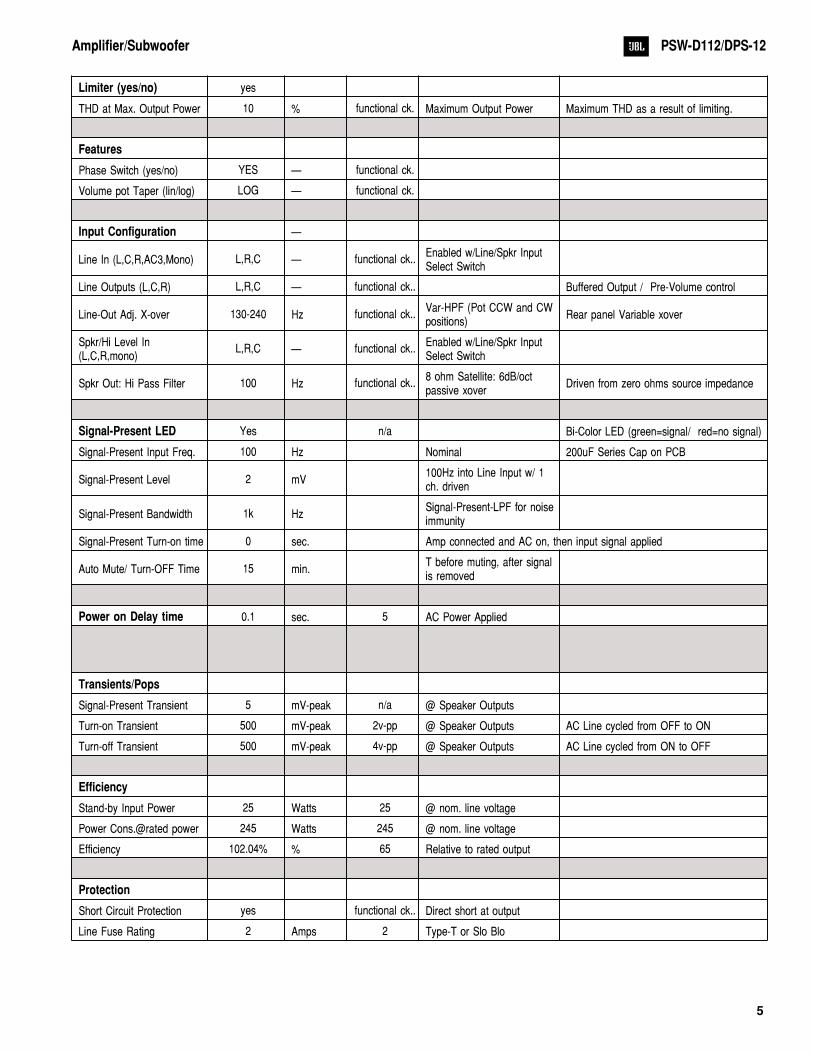
Limiter (yes/no) yes
THD at Max. Output Power 10 % functional ck. Maximum Output Power Maximum THD as a result of limiting.
Features
Phase Switch (yes/no) YES — functional ck.
Volume pot Taper (lin/log) LOG — functional ck.
Input Configuration —
Line In (L,C,R,AC3,Mono) L,R,C — functional ck..Enabled w/Line/Spkr InputSelect Switch
Line Outputs (L,C,R) L,R,C — functional ck.. Buffered Output / Pre-Volume control
Line-Out Adj. X-over 130-240 Hz functional ck..Var-HPF (Pot CCW and CWpositions)
Rear panel Variable xover
Spkr/Hi Level In(L,C,R,mono)
L,R,C — functional ck..Enabled w/Line/Spkr InputSelect Switch
Spkr Out: Hi Pass Filter 100 Hz functional ck..8 ohm Satellite: 6dB/octpassive xover
Driven from zero ohms source impedance
Signal-Present LED Yes n/a Bi-Color LED (green=signal/ red=no signal)
Signal-Present Input Freq. 100 Hz Nominal 200uF Series Cap on PCB
Signal-Present Level 2 mV100Hz into Line Input w/ 1ch. driven
Signal-Present Bandwidth 1k HzSignal-Present-LPF for noiseimmunity
Signal-Present Turn-on time 0 sec. Amp connected and AC on, then input signal applied
Auto Mute/ Turn-OFF Time 15 min.T before muting, after signalis removed
Power on Delay time 0.1 sec. 5 AC Power Applied
Transients/Pops
Signal-Present Transient 5 mV-peak n/a @ Speaker Outputs
Turn-on Transient 500 mV-peak 2v-pp @ Speaker Outputs AC Line cycled from OFF to ON
Turn-off Transient 500 mV-peak 4v-pp @ Speaker Outputs AC Line cycled from ON to OFF
Efficiency
Stand-by Input Power 25 Watts 25 @ nom. line voltage
Power Cons.@rated power 245 Watts 245 @ nom. line voltage
Efficiency 102.04% % 65 Relative to rated output
Protection
Short Circuit Protection yes functional ck.. Direct short at output
Line Fuse Rating 2 Amps 2 Type-T or Slo Blo
5
Amplifier/Subwoofer PSW-D112/DPS-12
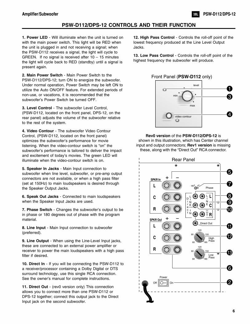
1. Power LED - Will illuminate when the unit is turned on
with the main power switch. This light will be RED when
the unit is plugged in and not receiving a signal; when
the PSW-D112 receives a signal, the light will cycle to
GREEN. If no signal is received after 10 – 15 minutes
the light will cycle back to RED (standby) until a signal is
present again.
2. Main Power Switch - Main Power Switch to the
PSW-D112/DPS-12; turn ON to energize the subwoofer.
Under normal operation, Power Switch may be left ON to
utilize the Auto ON/OFF feature. For extended periods of
non-use, or vacations, it is recommended that the
subwoofer's Power Switch be turned OFF.
3. Level Control - The subwoofer Level Control,
(PSW-D112, located on the front panel, DPS-12, on the
rear panel) adjusts the volume of the subwoofer relative
to the rest of the system.
4. Video Contour - The subwoofer Video Contour
Control, (PSW-D112, located on the front panel)
optimizes the subwoofer's performance for movie
listening. When the video-contour switch is “on” the
subwoofer's performance is tailored to deliver the impact
and excitement of today's movies. The green LED will
illuminate when the video-contour switch is on.
5. Speaker In Jacks - Main Input connection to
subwoofer when line level, subwoofer, or pre-amp output
connectors are not available, or when a high pass filter
(set at 150Hz) to main loudspeakers is desired through
the Speaker Output Jacks.
6. Speak Out Jacks - Connected to main loudspeakers
when the Speaker Input Jacks are used.
7. Phase Switch - Changes the subwoofer's output to be
in phase or 180 degrees out of phase with the program
material.
8. Line Input - Main Input connection to subwoofer
(preferred).
9. Line Output - When using the Line-Level Input jacks,
these are connected to an external power amplifier or
receiver to power the main loudspeakers with a high pass
filter if desired.
10. Direct In - If you will be connecting the PSW-D112 to
a receiver/processor containing a Dolby Digital or DTS
surround technology, use this single RCA connection.
See the owner's manual for complete instructions.
11. Direct Out - (rev0 version only) This connection
allows you to connect more than one PSW-D112 or
DPS-12 together; connect this output jack to the Direct
Input jack on the second subwoofer.
12. High Pass Control - Controls the roll-off point of the
lowest frequency produced at the Line Level Output
Jacks.
13. Low Pass Control - Controls the roll-off point of the
highest frequency the subwoofer will produce.
6
Amplifier/Subwoofer PSW-D112/DPS-12
min
max
video contour
level
60
90 150
180
120
60
90 150
180
120
180o 0o
Phase
LowPass
HighPass
Direct
LINE
IN
LINE
OUT
Direct Out
L
C
R
L
C
R
L
C
R
Power
OnOff
SPKR In
SPKR Out
Front Panel ( only)PSW-D112
Rev0 version PSW-D112/DPS-12
Rev1 version
of the isshown in this illustration, which has Center channel
input and output connectors; is missingthese, along with the “Direct Out” RCA connector.
Rear Panel
3
1
4
6
2
7
8
12
13
11
5
10
9
PSW-D112/DPS-12 CONTROLS AND THEIR FUNCTION
OPERATION
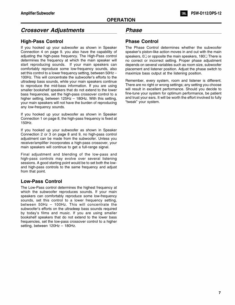
Crossover Adjustments
High-Pass Control
If you hooked up your subwoofer as shown in SpeakerConnection 4 on page 9. you also have the capability ofadjusting the high-pass frequency. The High-Pass controldetermines the frequency at which the main speaker willstart reproducing sounds. If your main speakers cancomfortably reproduce some low-frequency sounds, alsoset this control to a lower frequency setting, between 50Hz –100Hz. This will concentrate the subwoofer’s efforts to theultradeep bass sounds, while your main speakers continueto reproduce the mid-bass information. If you are usingsmaller bookshelf speakers that do not extend to the lowerbass frequencies, set the high-pass crossover control to ahigher setting, between 125Hz – 180Hz. With this setting,your main speakers will not have the burden of reproducingany low-frequency sounds.
If you hooked up your subwoofer as shown in SpeakerConnection 1 on page 8, the high-pass frequency is fixed at150Hz.
If you hooked up your subwoofer as shown in SpeakerConnection 2 or 3 on page 8 and 9, no high-pass controladjustment can be made from the subwoofer. Unless youreceiver/amplifier incorporates a high-pass crossover, yourmain speakers will continue to get a full-range signal.
Final adjustment and blending of the low-pass andhigh-pass controls may evolve over several listeningsessions. A good starting point would be to set both the low-and high-pass controls to the same frequency and adjustfrom that point.
Low-Pass Control
The Low-Pass control determines the highest frequency atwhich the subwoofer reproduces sounds. If your mainspeakers can comfortably reproduce some low-frequencysounds, set this control to a lower frequency setting,between 50Hz – 100Hz. This will concentrate thesubwoofer’s efforts on the ultradeep bass sounds requiredby today’s films and music. If you are using smallerbookshelf speakers that do not extend to the lower bassfrequencies, set the low-pass crossover control to a highersetting, between 120Hz – 180Hz.
Phase
Phase Control
The Phase Control determines whether the subwooferspeaker’s piston-like action moves in and out with the main
speakers, 0� , or opposite the main speakers, 180� . There isno correct or incorrect setting. Proper phase adjustmentdepends on several variables such as room size, subwooferplacement and listener position. Adjust the phase switch tomaximize bass output at the listening position.
Remember, every system, room and listener is different.There are no right or wrong settings; any setting you choosewill result in excellent performance. Should you decide tofine-tune your system for optimum performance, be patientand trust your ears. It will be worth the effort involved to fully“tweak” your system.
7
Amplifier/Subwoofer PSW-D112/DPS-12
SPEAKER CONNECTIONS
1) If your receiver/amplifier has nosubwoofer outputs or preamp outputsfor the left, center and right channels.See Figure 1.
2) If your receiver/amplifier hassubwoofer outputs or preamp outputjacks for the left and right channels.See Figure 2.
8
Amplifier/Subwoofer PSW-D112/DPS-12
NOTE: The rear plate for the PSW-D112 is shown, which has the level control on the front panel. The DPS-12 has thislevel control on the rear panel (amplifier). In addition, the Rev0 version of the PSW-D112/DPS-12 is shown in theseillustrations, which has Center channel input and output connectors; Rev1 version is missing these, along with the“Direct Out” RCA connector.
60
90 150
180
120
60
90 150
180
120
180o 0o
Phase
LowPass
HighPass
Direct
LINE
IN
LINE
OUT
Direct Out
L
C
R
L
C
R
L
C
R
SPKR In
SPKR Out
LEFTSPEAKER
RIGHTSPEAKER
SPEAKER OUTPUT
LEFT RIGHT
RECEIVER/AMPLIFIER
Figure 1
60
90 150
180
120
60
90 150
180
120
180o 0o
Phase
LowPass
HighPass
Direct
LINE
IN
LINE
OUT
Direct Out
L
C
R
L
C
R
L
C
R
SPKR In
SPKR Out
Figure 2
RIGHTLOUDSPEAKER
LEFTLOUDSPEAKER
MAIN SPEAKER OUTPUT
SUBWOOFER OUT
LEFT
LEFT
RIGHT
RIGHT
RECEIVER/AMPLIFIER

3a) If your receiver/amplifier has a single(mono) subwoofer output or LFE output,connect the output using a “Y”-connector(not included) to both Left or Right line-levelinputs on the subwoofer. Plug the singlemale end of the “Y” connector into thereceiver/amplifier, and connect the 2interconnect cables to the Left and Rightline-level inputs on the subwoofer.
3b) I f you wi l l be connect ing thePSW-D112/DPS-12 to a receiver/processorcontaining a Dolby Digital or D.T.S. surroundtechnology:
1. For the Rev0 version, connect thesubwoofer or LFE output from yourreceiver/processor to the Center.line-level input as shown in Figure 3b.
2. For the Rev1 version, (with no centerchannel input jack), connect thesubwoofer or LFE output from yourreceiver/processor to EITHER Left orRight line-level input jack with a singleRCA cable.
3. Set the “Low-Pass” control to the fullclockwise 180Hz setting.
The connection labeled “Direct” (on Rev0version of the subwoofer) is an output thatallows you to connect several subwoofers, ifyour system contains more than onesubwoofer.
4) If your receiver/amplifier has preampoutput jacks and main input jacks for the leftand right channels or you have a separatepre-amp/ processor and power amplifier.See Figure 4.
This method of hookup can offer the highestlevel of performance for your completeloudspeaker system. The PSW-D112/DPS-12 incorporates a variable high-passcrossover in addition to a variable low-passcrossover. When hooked up as shownabove, the subwoofer wi l l l im i t thelow-frequency information that is returned toyour receiver/amplifier. Your receiver/amplifier does not need to waste valuablepower reproducing the low frequencies. Inaddition, since no low-frequency informationis being sent to your main loudspeakers, theyare able to reproduce mid and highfrequencies with greater clarity
9
Amplifier/Subwoofer PSW-D112/DPS-12
180o 0o
Phase
Direct
LINE
IN
LINE
OUT
Direct Out
L
C
R
L
C
R
L
SPKR In
SPKR Out
Figure 3a
SUBWOOFEROUTput/LFE
RECEIVER/PREAMPLIFIER
Figure 3b
SUBWOOFEROUTPUT
RECEIVER/PREAMPLIFIER180o 0o
Phase
Direct
LINE
IN
LINE
OUT
Direct Out
L
C
R
L
C
R
L
SPKR In
SPKR Out
60
90 150
180
120
60
90 150
180
120
180o 0o
Phase
LowPass
HighPass
Direct
LINE
IN
LINE
OUT
Direct Out
L
C
R
L
C
R
L
C
R
SPKR In
SPKR Out
Figure 4
RIGHTLOUDSPEAKER
LEFTLOUDSPEAKER
MAIN SPEAKER OUTPUTLEFTRIGHT
RIGHT
CENTER
LEFT
RECEIVER/AMPLIFIER
PREOUT
MAININ

TROUBLESHOOTING
If you used the high-level (speaker) inputs and
there is no sound from any of the speakers, check
the following:
� Receiver/amplifier is on and a source is playing.
� Powered subwoofer is plugged in.
� Check all wires and connections between
receiver/amplifier and speakers. Make sure all wires
are connected. Make sure none of the speaker
wires are frayed, cut or punctured.
� Review proper operation of your receiver/amplifier.
If there is low bass output, check the following:
� Make sure the connections to the left and right
“Speaker Inputs” have the correct polarity (+ and –).
� Make sure that the subwoofer is plugged into an
active electrical outlet.
� Adjust the crossover point.
� Flip the Phase Control Switch to the opposite
position.
� If you are using a Dolby* Digital/DTS� receiver or
processor, make sure that the subwoofer
adjustments on the receiver/processor are set up
correctly.
� Slowly turn the level Control clockwise until you
begin to hear the desired amount of bass.
If you used the line-level inputs and there is no
sound from the subwoofer, check the following:
� Receiver/amplifier is on and a source is playing.
� Powered subwoofer is plugged in.
� Check all wires and connections between receiver/
amplifier and subwoofer. Make sure all wires are
connected. Make sure none of the wires are frayed,
cut or punctured.
� Review proper operation of your receiver/amplifier.
� Slowly turn the level Control clockwise until you
begin to hear the desired amount of bass.
� Make sure that you have configured your
receiver/processor so that the subwoofer/LFE output
is on.
1 0
Amplifier/Subwoofer PSW-D112/DPS-12
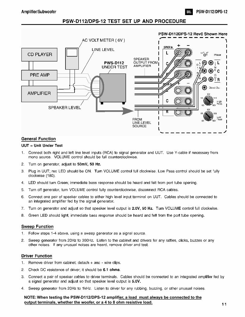
NOTE: When testing the PSW-D112/DPS-12 amplifier, a load must always be connected to theoutput terminals, whether the woofer, or a 4 to 8 ohm resistive load.

1 2
Amplifier/Subwoofer PSW-D112/DPS-12
PSW-D112/DPS-12 TESTING PROCEDURE (REV0 ONLY)
A. Power Amp Section
1. Resistance Check Resistance from O/P of the module to GND should be >1M (NO LOAD)Resistance from V+ of the module to V- of the module should read >5kResistance from V+ of the module to O/P of the module should read >1MResistance from V- of the module to O/P of the module should read >1M
2. Power Up LED RED
- With a 35mV signal to Low level input, LED should change to GREEN
3. D.C. Operation
-Voltage measurements (DVM)
Between +6V V+ O/P V- +15V S/D FR I/P GND -15VAnd V- GND GND GND GND V- GND GND GND GNDShouldbeReading
+6.2V +90.1V 0V -90.1V +15.5V +5.75V 0V 0V 0V -15.5V
4. Check Switching Frequency
-Use scope (EITHER USES AN ISOLATION TRANSFORMER OR ATTACHES THE PROBE TIP TO SPK- and REFERENCE LEAD TO SPK+)
-Reading 100kHz +/-10%,500mVpp
B. Pre Amp Section
1. Low Level Input Sensitivity -Set up Turn level and Low-Pass Pot Fully CW
Generator set at 100mV@39HzSignal to Low level input
-Voltage measurements
OP AMPU1(14) U1(7) U1(1) U2(8) U2(14) U2(1) U4(1) U4(7)
SPEAKEROUTPUT
271mV 409mV 486mV 471mV 456mV 460mV 2.94V 2.67V 17.4V
2. High Level Input Sensitivity
-Set up Turn level and Lo Pass Pot Fully CW Set Generator at 3.6V@39Hz
Signal to High level input
-Voltage measurements 17.4V at speaker output

1 3
Amplifier/Subwoofer PSW-D112/DPS-12
3. Low-Pass
-Set up Set Generator at 100mV@100HzSignal to Low level inputMeasure voltage at speaker output
-Voltage measurement
Low-Pass Pot Setting OutputCW 12.2V
CCW 1.2V
4. High-Pass
-Set up Set Generator at 100mV@100HzSignal to Low level inputMeasure voltage at high-pass output
-Voltage measurement
High-Pass Pot Setting OutputCW 24mV
CCW 55mV
5. Direct out
-Set up Set Generator at 100mV@100HzSignal to Low level input
-Voltage measurement 100mV at direct out
See flow chart next page for diagnostics.
1 4
Amplifier/Subwoofer PSW-D112/DPS-12
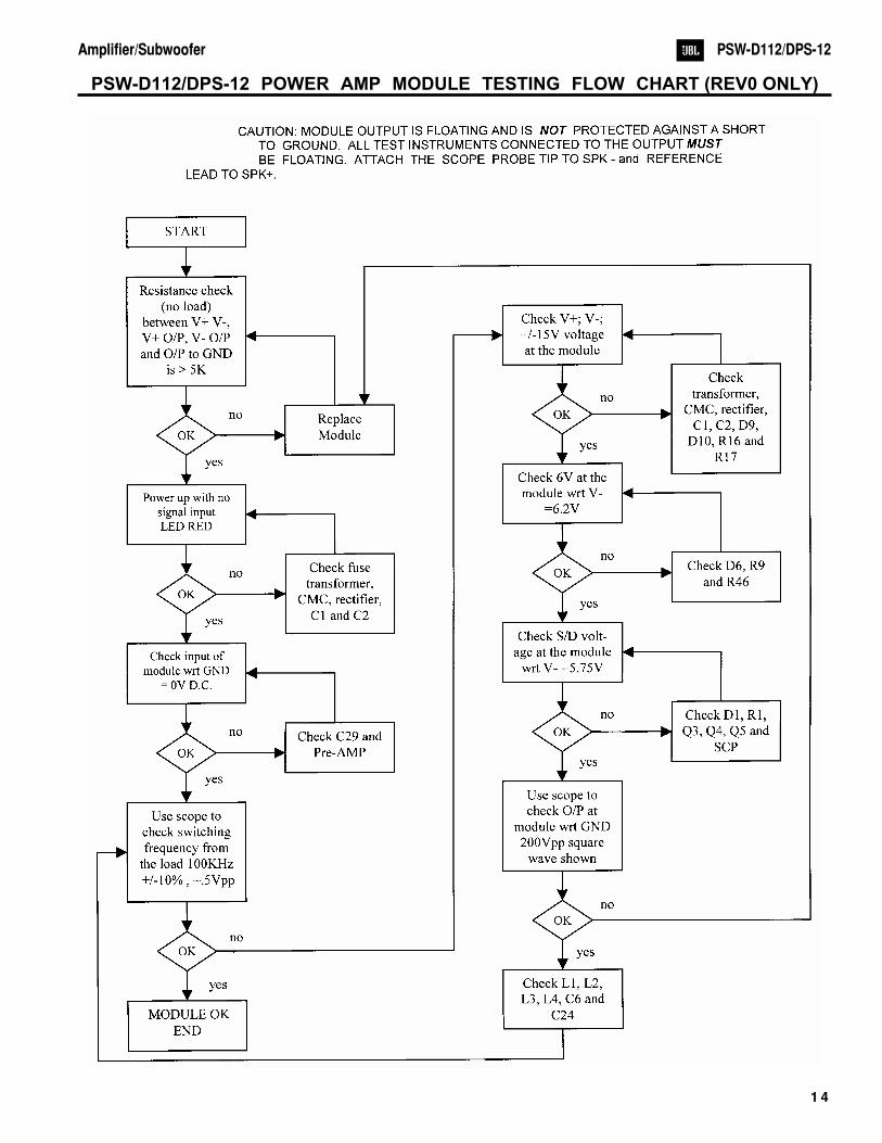
PSW-D112/DPS-12 POWER AMP MODULE TESTING FLOW CHART (REV0 ONLY)

JBL Incorporated 250 Crossways Park Dr. Woodbury, New York 11797 (516) 496-3400
Service BulletinService Bulletin JBL9903 Rev1 - February 2001 This is considered a Minor repair
To: All JBL Service Centers
Models: PSW-D110, PSW-D112, ARC SUB 8, ARC SUB 10
Subject: Check Solder Joints in Event of Failure
Some performance related complaints in the PSW-D110, PSW-D112, ARC SUB 8 or ARC SUB 10 poweredSubwoofers may be caused by cold solder connections between the 28 pins of the Power Amp Module and themain circuit board. When troubleshooting, failure to check these joints can result in erroneous conclusions orwasted time.
In the event you receive a PSW-D110, PSW-D112, ARC SUB 8 or ARC SUB 10 Subwoofer with thecomplaints “Dead, or No Output, or Motorboating (Oscillation)”, perform the steps listed below first beforeany further troubleshooting takes place:
1) Unplug all cables, lay the subwoofer on a padded surface.2) Remove all Philips screws around the outer perimeter of the amplifier faceplate.3) Remove amplifier assembly; you should be able to remove the amplifier far enough out of the cabinet to service it
without removing the woofer wires.4) Locate the Power Amp Module; it is the large gray component with a metal case. On the solder side of the circuit
board are the 28 soldered connections to the Module.5) Regardless of whether you can visibly see breaks in any of the connections or not, carefully re-solder all 28 pin
connections, adding 60/40 rosin core solder. Take care not “bridge” any connections on the board with solder.6) Inspect the solder joints to the main filter capacitors C1 and C2 on the main PCB and re-solder if needed.7) Replace the amplifier assembly back into the cabinet; replace the screws.8) Test the unit by applying a signal from a music source, adjust the volume to a moderate level and confirm the
original problem has been corrected.
IMPORTANT SERVICE NOTES: When testing the PSW-D, or ARC Series amplifier, a load must always beconnected to the output terminals, whether the woofer, or a 4 to 8 ohm resistive load.All AC powered test instruments (meters, oscilloscopes, etc.) must have a floating ground, i.e. be connected toan isolation transformer.
15
JBL Incorporated 250 Crossways Park Dr. Woodbury, New York 11797 (516) 496-3400
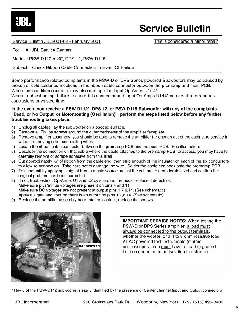
Service BulletinService Bulletin JBL2001-02 - February 2001 This is considered a Minor repair
To: All JBL Service Centers
Models: PSW-D112 rev0*, DPS-12, PSW-D115
Subject: Check Ribbon Cable Connection In Event Of Failure
Some performance related complaints in the PSW-D or DPS Series powered Subwoofers may be caused bybroken or cold solder connections in the ribbon cable connector between the premamp and main PCB.When this condition occurs, it may also damage the Input Op-Amps U1/U2.When troubleshooting, failure to check this connector and Input Op-Amps U1/U2 can result in erroneousconclusions or wasted time.
In the event you receive a PSW-D112*, DPS-12, or PSW-D115 Subwoofer with any of the complaints“Dead, or No Output, or Motorboating (Oscillation)”, perform the steps listed below before any furthertroubleshooting takes place:
1) Unplug all cables, lay the subwoofer on a padded surface.2) Remove all Philips screws around the outer perimeter of the amplifier faceplate.3) Remove amplifier assembly; you should be able to remove the amplifier far enough out of the cabinet to service it
without removing other connecting wires.4) Locate the ribbon cable connector between the premamp PCB and the main PCB. See illustration.5) Desolder the connection on that cable where the cable attaches to the premamp PCB; to access, you may have to
carefully remove or scrape adhesive from this area.6) Cut approximately ½” of ribbon from the cable end, then strip enough of the insulator on each of the six conductors
to allow re-connection. Take care not to damage the wire. Solder the cable end back onto the premamp PCB.7) Test the unit by applying a signal from a music source, adjust the volume to a moderate level and confirm the
original problem has been corrected.8) If not, troubleshoot Op-Amps U1 and U2 by standard methods; replace if defective:
Make sure plus/minus voltages are present on pins 4 and 11.Make sure DC voltages are not present at output pins 1,7,8,14. (See schematic)Apply a signal and confirm there is an output on pins 1,7,8,14. (See schematic)
9) Replace the amplifier assembly back into the cabinet; replace the screws.
* Rev 0 of the PSW-D112 subwoofer is easily identified by the presence of Center channel Input and Output connectors
IMPORTANT SERVICE NOTES: When testing thePSW-D or DPS Series amplifier, a load mustalways be connected to the output terminals,whether the woofer, or a 4 to 8 ohm resistive load.All AC powered test instruments (meters,oscilloscopes, etc.) must have a floating ground,i.e. be connected to an isolation transformer.
16

TECH TIPS
Troubleshooting tips and solutions to common service problems For models: PSWD112 Rev1 only * TIP# JBLTT2004-02
PSWD115 Subject: PSWD112/115 WIRING TO REMOTE VOLUME/CONTOUR/LED CONTROL PLATE
A total of 9 wires travel from two Molex connectors on amplifier PCB to 334344-001 Control plate. That control panel is attached by two screws on the inside of the cabinet; the woofer must be removed. The wire cluster is glued into the cabinet opening at the rear of the control panel. The hot melt glue has to be cut out and pried out, then the wire cluster should be re-glued after the control panel is serviced, for air integrity.
1) Two Black sheathed cables, each containing wire colors: Black or Blue White Red
2) Three separate wires: Red White Gray
At the Control Plate: Volume pot: Black or Blue, White, Red Contour Switch: Black or Blue, White, Red Power LED: Gray, Red Contour LED: White, Black w/ 10k resistor
* Rev1 version of the PSW-D112 subwoofer is easily identified by the absence of Center channel Input and Output connectors, and is missing the“Direct Out” RCA connector.
17
Amplifier/Subwoofer PSW-D112/DPS-12

CABINET EXPLODED VIEWS
SCREWS (12)
SCREWS (8)
JBL Logo#200512
FEET#200582
CABINETNOT FORSALE
12" WOOFER#200700
AMPLIFIERASSEMBLY
SCREWS (12)
SCREWS (8)
FOOT PART 1#200670
FOOT PART 2#200870
CABINETNOT FORSALE
12" WOOFER#200700
AMPLIFIERASSEMBLY
DPS-12CABINET ASSEMBLY
PSW-D112CABINET ASSEMBLY
GRILLE#200710
CONTROLPANEL#200760
VOLUME KNOB#70313
VIDEO CONT.BUTTON#70314
VIDEO CONT.SWITCH#70152
18
Amplifier/Subwoofer PSW-D112/DPS-12
5 5
4 4
3 3
2 2
1 1
A
A
B
B
C
C
D
D
E
E
F
F
G
G
PSW-D112/DPS-12
Rev0
(PSW-D112 shown here)
Amplifier AssemblyExploded View
shown here
13
14
12
17
15
11
6
1 9
7
2
5
16
4
8
10
S6
4A
MI
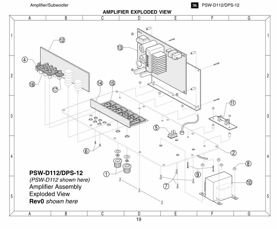
AMPLIFIER EXPLODED VIEW
19
Amplifier/Subwoofer PSW-D112/DPS-12
PSW-D112/DPS-12 MECHANICAL PARTS LIST
Ref. # Part Number Description Qty
PSW-D112/DPS-12
1 70302 Knob, 3 pcs on DPS-12, 2 pcs on PSW-D112
2 70312 Faceplate PSW-D112
2 70311 Faceplate DPS-12
3 70316 Amp PCB support
4 70150 Phase switch 1(also DPS-12 Video Contour switch)
5 70151 Power switch Safety part
6 70170 #4x0.5" Screws to secure input jack
7 70171 #10 x 1" Screw machine screwBolts for transformer 4 per unit
8 70172 #10 keps Nuts for transformer 4 per unit 4
9 70173 #6 x 0.5" Screws for fuse PCB 2per unit 2
10 80116 Transformer #4632 Safety part 1
11 80117 250V, 2.0A, T type SLO BLO fuse Safety part
12 80118 Preamp board, D112,D115,DPS12 Safety part
13 80119 Power amp board D112, D115,DPS12Safety part
14 80120 High level input PCB D112,D115,DPS12Safety part
15 108116 High level 5way binding post(pr) (4) or (6)
16 108322 Six line RCA input jack (Rev0) 1108321 Quad RCA input jack (Rev1) 1
17 108323 Single RCA input jack (Rev0 version only) 1
20
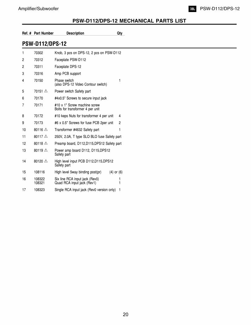
Amplifier/Subwoofer PSW-D112/DPS-12
PACKING EXPLODED VIEWS
DPS-12
PSW-D112
WARRANTY CARD
OWNER'S MANUAL#200730 (120V)
#331993-001
WARRANTY CARD#331993-001
OWNER'S MANUAL#200830 (120V)
TOP FOAM PAD#200722
TOP STYROFOAMRAILS (2)PER BOX#200821
PSW-D112
DPS-12
BOTTOMFOAM PAD#200721
BOTTOMSTYROFOAMRAILS (2)PER BOX#200822
CARTON#200720
CARTON#200820
BOTTOMSTYROFOAMPAD#200824
PLASTIC BAG
PLASTIC BAG
DPS-12
PSW-D112
21
Amplifier/Subwoofer PSW-D112/DPS-12
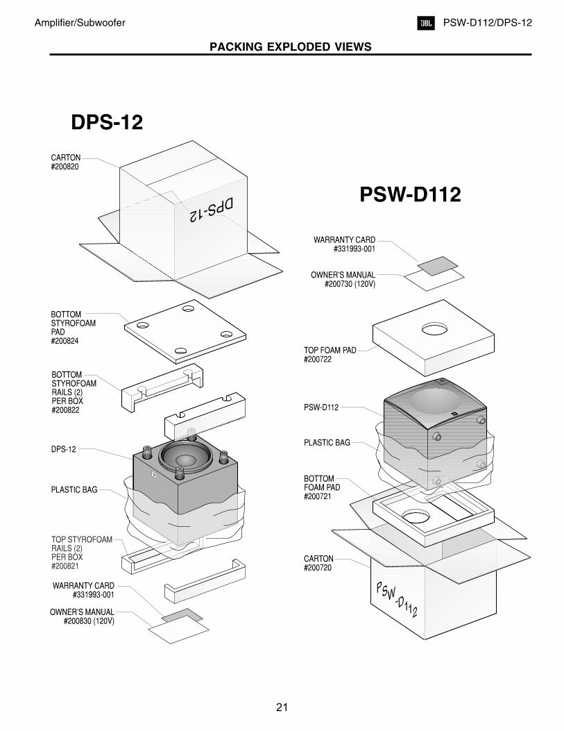
PSW-D112/DPS-12 Rev0 PCB (Component Side)
Re
v0
-C
om
po
ne
nt
Sid
eT
race
La
ye
r
55
44
33
22
11
A A
B B
C C
D D
E E
F F
G G
22
Amplifier/Subwoofer PSW-D112/DPS-12
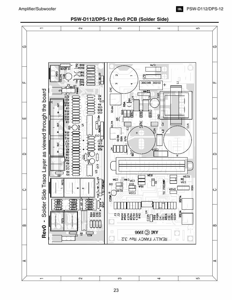
PSW-D112/DPS-12 Rev0 PCB (Solder Side)
Re
v0
-S
old
er
Sid
eT
race
La
ye
ra
svie
we
dth
rou
gh
the
bo
ard
55
44
33
22
11
A A
B B
C C
D D
E E
F F
G G
23
Amplifier/Subwoofer PSW-D112/DPS-12
Re
v1
-C
om
po
ne
nt
Sid
eT
race
La
ye
r
55
44
33
22
11
A A
B B
C C
D D
E E
F F
G G
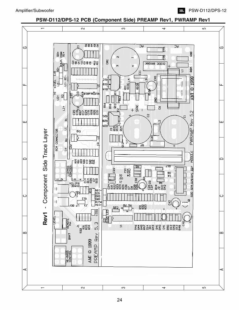
PSW-D112/DPS-12 PCB (Component Side) PREAMP Rev1, PWRAMP Rev1
24
Amplifier/Subwoofer PSW-D112/DPS-12

Re
v1
-S
old
er
Sid
eT
race
La
ye
ra
svie
we
dth
rou
gh
the
bo
ard
55
44
33
22
11
A A
B B
C C
D D
E E
F F
G G
PSW-D112/DPS-12 PCB (Solder Side) PREAMP Rev1, PWRAMP Rev1
25
Amplifier/Subwoofer PSW-D112/DPS-12

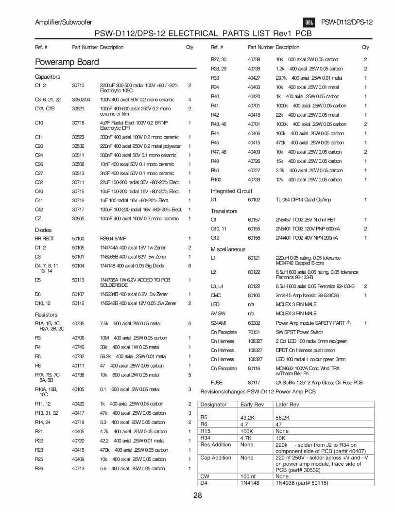
PSW-D112/DPS-12 ELECTRICAL PARTS LIST (Rev0)
Preamp Board
Low Pass 40436 20k� 0.25W 10% Quad Lin Pot 1
Level 40402 5k� 0.25W 10% Single Linear Pot 1
High pass 40450 20k� 0.25W 10% 3-gang Tandem Lin Pot 1
Capacitors
Safety C1 30502 100nF 50V 20% Mono-ceramic axial 1
C2, C3 30501 47nF 50V 20% Mono-ceramic axial 2
CE3 30708 47uF 16V 20% Electrolytic Radial 1
C4 30501 47nF 50V 20% Mono-ceramic axial 1
C5 30100 330pF 50V 20% Mono-ceramic axial 1
C6, 24, 25 30501 47nF 50V 20% Mono-ceramic axial 3
C7, 9 30100 330pF 50V 20% Mono-ceramic axial 2
C8 30101 220pF 50V 20% Mono-ceramic axial 1
C10 30502 100nF 50V 20% Mono-ceramic axial 1
C11, 12 30517 68nF 50V 10% Mono-ceramic axial 2
C13, 14, 15 30101 220pF 50V 20% Mono-ceramic axial 3
C16 30504 100nF 50V 10% Mono-ceramic axial 1
C17 30502 100nF 50V 20% Mono-ceramic axial 1
C18 Jumper
C19 30508 10nF 50V 10% Mono-ceramic axial 1
C20, 21, 22, 23 30504 100nF 50V 10% Mono-ceramic axial 4
Resistors
R1 40405 4.7k� 0.25W 5% carbon film 1
R2 40431 68k� 0.25W 1% metal film 1
R3 40451 137k� 0.25W 1% metal film 1
R4 40452 2.7k� 0.25W 5% carbon film 1
R5, 6 40438 20k� 0.25W 1% metal film 2
R7 40108 620� 0.25W 5% carbon film 1
R8 40453 20k� 0.25W 5% carbon film 1
R9, 10, 13 40438 20k� 0.25W 1% metal film 3
R11, 12, 14 40108 620� 0.25W 5% carbon film 3
R15 40732 56.2k� 0.25W 1% metal film 1
R16 40743 7.5k� 0.25W 5% carbon film 1
R17, 18 40453 20k� 0.25W 5% carbon film 2
R19, 20 40108 620� 0.25W 5% carbon film 2
R21 40412 33.2k� 0.25W 1% metal film 1
R22 40454 45.3k� 0.25W 1% metal film 1
R23 40405 4.7k� 0.25W 1% metal film 1
R24 40408 8.45k� 0.25W 1% metal film 1
R25 40455 169k� 0.25W 1% metal film 1
R27 40434 38.3k� 0.25W 1% metal film 1
R28 40456 2.7k� 0.25W 5% carbon film 1
R32 40403 10k� 0.25W 1% metal film 1
R33, 34, 35, 36, 40440 6.8k� 0.25W 5% carbon film 549
R37, 38 40438 20k� 0.25W 1% metal film 2
R42 40457 200k� 0.25W 5% carbon film 1
R43 Jumper
R45 40449 3.3k� 0.25W 5% carbon film 1
R46, 47 40415 470k� 0.25W 5% carbon film 2
R48 40742 4.99k� 0.25W 1% metal film 1
Diodes
Signal LED 50109 Bi-colour 1
Video LED 50110 Green 1
Transistors
TR1 60154 MPS A56 80V PNP 1
TR2 60151 MPS A13 40V NPN(Darl) 1
Integrated Circuit
U1 , U2 60100 LM324 Dual OpAmp +/-15V 2
U3 60101 TLO 82 Dual OpAmp +/-15V 1
Poweramp Board
Capacitors
C1 , C2 30710 2200uF 100V 80/-20% Electrolytic radial 2
C3 , C4, C5 30505 100nF 50V 20% mono-ceramic axial 3
C4, 5 30505 100nF 50V 20% mono-ceramic axial 2
C6 30709 4.7uF 100V 80/-20% Electrolytic radial NP 1
C7a/b 30521 100nF 250V 20% Metal Polyester Rad 2
C8 30502 100nF 50V 20% mono-ceramic axial 1
C21 30522 100nF 250V 20% mono-ceramic axil 1
C24 30523 330nF 100V 80/-20% mono-ceramic axial 1
C26 30508 10nF 50V 10% mono-ceramic axial 1
C27 30513 3.3nF 50V 10% mono-ceramic axial 1
C29 30711 22uF 35V 80/-20% Electrolytic radial 1
C31 30511 330nF 50V 20% mono-ceramic axial 1
CW, CZ 30505 100nF 100V 20% mono-ceramic axial 2
Diodes
D1 50114 1N5265B 62V 5% .5W Zener 1
D2, 4 50104 1N4148 100V .1A 2
D6 50103 1N5234B 6.2V 5% .5W Zener 1
D9, D10 50105 1N4744A 15V 5% 1W Zener 2
DBR 50100 Bridge Rect 200V 4A 1
Semiconductors
Q3 60153 2N3904 40V NPN 1
Q4, Q5 60155 2N5401 PNP 2
U4 60101 TL082 Dual Op Amp 1
S64AMI 60302 Power Amp module SAFETY PART 1
2 5
Amplifier/Subwoofer PSW-D112/DPS-12
Ref. # Part Number Description Qty Ref. # Part Number Description Qty
26

Resistors
R1 40706 10M� 0.25W 5% carbon film 1
R3 40458 43.2k� 0.25W 1% metal film 1
R4 40417 47k� 0.25W 5% carbon film 1
R4a/b/c 40105 0.1� 0.5W 5% metal film 3
R5, 6 40420 1k� 0.25W 5% carbon film 2
R7 40449 3.3k� 0.25W 5% carbon film 1
R8, 25 40417 47k� 0.25W 5% carbon film 2
R9 40744 3.3k� 5W 5% ceramic wirewound 1
R14 40409 10k� 0.25W 5% carbon film 1
R15 40459 100k� 0.5W 5% carbon film 1
R16, 17 40745 1.8k� 7W 5% ceramic wirewound 2
R23 40461 20k� 0.5W 5% carbon film 1
R24 40418 22k� 0.25W 5% carbon film 1
R33, 50 40100 332� 0.5W 5% carbon film 2
R46 40111 47 ohms 0.25W 5% carbon film 1
R49 40746 316k� 0.25W 1% metal film 1
R51 40417 47k� 0.25W 5% carbon film 1
R52, R57 40462 2.7k� 5W 5% ceramic wirewound 2
R58, 59 40405 4.7k� 0.25W 5% carbon film 2
R60 40431 68k� 0.25W 5% carbon film 1
R61 40463 3.9k� 3W 5% ceramic wirewound 1
SafetyInductorsCMC1 80100 mc4438 1
L1 80121 mc4642 1
“L2,L3,L4" 80122 Ferrite Bead 3
High Level Input/OutputBoard
CapacitorsC1 30704 220uF 50V 20% Electrolytic Radial 1
C2 30704 220uF 50V 20% Electrolytic Radial 1
C3 30704 220uF 50V 20% Electrolytic Radial 1
Resistors
R1 L, R3 L, 40406 100k� 0.25W 5% carbon film 6R1 C, R3 C,R1 R, R3 R
R2 L, R2 C, R2 R 40405 4.7k� 0.25W 5% carbon film 3
Miscellaneous1 70302 Knob, 3 pcs on DPS-12, 2 pcs on PSW-D112
2 70312 Faceplate PSW-D112
2 70311 Faceplate DPS-12
3 70316 Amp PCB support
4 70150 Phase switch 1(also DPS-12 Video Contour switch)
5 70151 Power switch Safety part
6 70170 #4x0.5" Screws to secure input jack
7 70171 #10 x 1" Screw machine screwBolts for transformer 4 per unit
8 70172 #10 keps Nuts for transformer 4 per unit 4
9 70173 #6 x 0.5" Screws for fuse PCB 2per unit 2
10 80116 Transformer #4632 Safety part 1
11 80117 250V, 2.0A, T type SLO BLO fuse Safety part
12 80118 Preamp board, D112,D115,DPS12 Safety part
13 80119 Power amp board D112, D115,DPS12Safety part
14 80120 High level input PCB D112,D115,DPS12Safety part
15 108116 High level 5way binding post(pr) (4) or (6)
16 108322 Six line RCA input jack 1
17 108323 Single RCA input jack (Rev0 version only) 1
RevisionsDate Issue Details18/11/98 2 “R23(20k,.25W) to 3.9k 3W, U3 added”
19/11/98 3 “U2 changed to U4, D1(90V) to 62V,”
11/26/1998 4 “R61A added, R24(8.66k) to 8.45k”
12/1/1998 5 “R15(39k) to 38.3k, R18/R15A added,R42(330k) to 200k)”
1/20/1999 7 “R20(1%MF) to 5%CF, R15A(.5W) to .25W”
2/22/1999 9 “R46(1000k) to 470k, C21/CW/CZ changedto poly film”
6/8/1999 10 “R16/R17(2.4k,5W) to 1.8k, 5W. 2.4k (5W) canbe used with 6.8, 3W metal oxide in parallel”
9/2/1999 11 “R16(4.7k) to 7.5k. C3(47n) to 100n, R9(3.9k) to3.3k, R61(5.1k,2W) to 3.9k,3W. PCB now rev 3.2"
2 6
Amplifier/Subwoofer PSW-D112/DPS-12
Ref.# PartNumber Description Qty Ref.# PartNumber Description Qty
27
PSW-D112/DPS-12 ELECTRICAL PARTS LIST Rev1 PCB
Poweramp Board
Capacitors
C1, 2 30710 2200uF 300-500 radial 100V +80 / -20% 2Electrolytic 105C
C3, 6, 21, 22, 30502/04 100N 400 axial 50V 0.2 mono ceramic 4
C7A, C7B 30521 100nF 400-600 axial 250V 0.2 mono 2ceramic or film
C10 30718 4u7F Radial Elect 100V 0.2 BP/NP 1Electrolytic DF1
C11 30523 330nF 400 axial 100V 0.2 mono ceramic 1
C20 30532 220nF 400 axial 250V 0.2 metal polyester 1
C24 30511 330nF 400 axial 50V 0.1 mono ceramic 1
C26 30508 10nF 400 axial 50V 0.1 mono ceramic 1
C27 30513 3n3F 400 axial 50V 0.1 mono ceramic 1
C32 30711 22uF 100-200 radial 35V +80/-20% Elect. 1
C40 30715 10uF 100-200 radial 16V +80/-20% Elect. 1
C41 30716 1uF 100 radial 16V +80/-20% Elect. 1
C42 30717 100uF 100-200 radial 16V +80/-20% Elect. 1
CZ 30505 100nF 400 axial 100V 0.2 mono ceramic 1
Diodes
BR RECT 50100 RS604 6AMP 1
D1, 2 50105 1N4744A 400 axial 15V 1w Zener 2
D3 50101 1N5265B 400 axial 62V .5w Zener 1
D4, 7, 8, 11 50104 1N4148 400 axial 0.05 Sig Diode 613, 14
D5 50113 1N4735A 1W 6.2V ADDED TO PCB 1SOLDERSIDE
D6 50107 1N5234B 400 axial 6.2V .5w Zener 1
D10, 12 50112 1N5242B 400 axial 12V 0.05 .5w Zener 2
Resistors
R1A, 1B, 1C 40735 7.5k 600 axial 2W 0.05 metal 6R2A, 2B, 2C
R3 40706 10M 400 axial .25W 0.05 carbon 1
R4 40740 33k 400 axial 1W 0.05 metal 1
R5 40732 56.2k 400 axial .25W 0.01 metal 1
R6 40111 47 400 axial .25W 0.05 carbon 1
R7A, 7B, 7C 40738 10k 600 axial 2W 0.05 metal 58A, 8B
R10A, 10B, 40105 0.1 600 axial .5W 0.05 metal 310C
R11. 12 40420 1k 400 axial .25W 0.05 carbon 2
R13, 31, 32 40417 47k 400 axial .25W 0.05 carbon 3
R14, 24 40718 3.3 400 axial .25W 0.05 carbon 2
R21 40405 4.7k 400 axial .25W 0.05 carbon 1
R22 40720 42.2 400 axial .25W 0.01 metal 1
R23 40415 470k 400 axial .25W 0.05 carbon 1
R25 40409 10k 400 axial .25W 0.05 carbon 1
R26 40713 5.6 400 axial .25W 0.05 carbon 1
R27, 30 40738 10k 600 axial 2W 0.05 carbon 2
R28, 29 40739 1.2k 400 axial .25W 0.05 carbon 2
R33 40427 23.7k 400 axial .25W 0.01 metal 1
R34 40403 10k 400 axial .25W 0.01 metal 1
R40 40420 1k 400 axial .25W 0.05 carbon 1
R41 40701 1000k 400 axial .25W 0.05 carbon 1
R42 40418 22k 400 axial .25W 0.05 metal 1
R43, 46 40701 1000k 400 axial .25W 0.05 carbon 2
R44 40406 100k 400 axial .25W 0.05 carbon 1
R45 40415 470k 400 axial .25W 0.05 carbon 1
R47, 48 40409 10k 400 axial .25W 0.05 carbon 2
R49 40726 15k 400 axial .25W 0.05 carbon 1
R50 40727 2.2k 400 axial .25W 0.05 carbon 1
R100 40733 12k 400 axial .25W 0.05 carbon 1
Integrated Circuit
U1 60102 TL 064 DIP14 Quad OpAmp 1
Transistors
Q1 60157 2N5457 TO92 25V N-chnl FET 1
Q10, 11 60155 2N5401 TO92 120V PNP 600mA 2
Q12 60156 2N4401 TO92 40V NPN 200mA 1
Miscellaneous
L1 80121 220uH 0.05 rating, 0.05 toleranceMCI4742 Gapped E-core
L2 80122 8.5uH 600 axial 0.05 rating, 0.05 toleranceFerronics 92-133-B
L3, L4 80122 8.5uH 600 axial 0.05 Ferronics 92-133-B 2
CMC 80100 2m2H 5 Amp Neosid 28-523C36 1
LED n/a MOLEX 3 PIN MALE
AV SW n/a MOLEX 3 PIN MALE
S64AMI 60302 Power Amp module SAFETY PART 1
On Faceplate 70151 SW SPST Power Switch
On Harness 108327 2 Col LED 100 radial 3mm red/green
On Harness 108327 DPDT On Harness push on/on
On Harness 108327 LED 100 radial 1 colour green 3mm
On Faceplate 80116 MCI4632 100VA Conc Wnd TRXw/Therm Brkr Pri.
FUSE 80117 2A SloBlo 1.25" 2 Amp Glass; On Fuse PCB
2 7
Amplifier/Subwoofer PSW-D112/DPS-12
Ref. # Part Number Description Qty Ref. # Part Number Description Qty
Revisions/changes PSW-D112 Power Amp PCB
Designator Early Rev Later Rev
R5 43.2K 56.2KR6 4.7 47R15 100K NoneR34 4.7K 10KRes Addition None 220k - solder from J2 to R34 on
component side of PCB (part# 40407)Cap Addition None 220 nf 250V - solder across +V and –V
on power amp module, trace side ofPCB (part# 30532)
CW 100 nf NoneD4 1N4148 1N4938 (part# 50115)
28
Preamp Board
Capacitors
C1, 2 30707/04 200uF 200 radial 50V 0.2 BP Electrolytic 2
C3, 4, 5, 6 30101 220pF 400 axial 50V 0.2 mono ceramic 4
C7 0.0R Jumper 400 axial 50V 1
C8, 9 30517 68n 400 axial 50V 0.05 mono ceramic 2
C10, 11, 12, 13 30504 100nF 400 axial 50V 0.1 mono ceramic 4
C14, 15, 16, 17 30514 47nF 400 axial 50V 0.1 mono ceramic 4
C18, 19 30100 330pF 400 axial 50V 0.2 mono ceramic 2
C20, 21, 22, 23 30502/04 100nF 400 axial 50V 0.2 mono ceramic 4
Integrated Circuits
U1 60100 LM324 DIP14 Quad OpAmp 1
U2 60102 TLO 64 DIP14 Low Power Quad OpAmp 1
Resistors
R1, 2 40405 4.7k� 400 axial .25W 0.05 carbon 2
R3, 4, 5, 6 40406 100k� 400 axial .25W 0.05 carbon 4
R8, 9 40452 2.7k� 400 axial .25W 0.05 carbon 2
R10 40453 20k� 400 axial .25W 0.05 carbon 1
R11 40749 75k� 400 axial .25W 0.05 carbon 1
R12 40504 45.3k� 400 axial .25W 0.01 metal 1
R13 40412 33.2k� 400 axial .25W 0.01 metal 1
R14 40709 68.1k� 400 axial .25W 0.01 metal 1
R16 40434 38.3k� 400 axial .25W 0.01 metal 1
R17 40455 169k� 400 axial .25W 0.01 metal 1
R18, 19, 20, 22 40722 6.8k� 400 axial .25W 0.05 carbon 4
R24, 26, 27, 30 40109 604� 400 axial .25W 0.01 metal 4
R25, 28, 31, 32 40438 20k� 400 axial .25W 0.01 metal 633, 34
R35 40451 137k� 400 axial .25W 0.01 metal 1
Miscellaneous
Level 40402 5k� Single Pot on harness 0.2 LOG 1
Remote n/a Molex Connector 100 3pin female 1
LoPass control 40707 20k� 4 gang Pot 0.2 1
Linear HiPass 40707 20k� 4 gang Pot 0.2 1control
Phase Switch 70150 SW SPDT In Line 1
RCA CONN. 108321 Quad Right Angle Quad RCA 1
J1, 3 0.0� Jumper 400 axial .25W 2
2 8
Amplifier/Subwoofer PSW-D112/DPS-12
Ref. # Part Number Description Qty Ref. # Part Number Description Qty
29

PSW-D112/DPS-12 INTEGRATED CIRCUITS
U1, U2 - (LM324 TL064) Quad Op AmpU3, U4 - (TLO 82) Dual Op Amp
1 52 63 74
14 1013 912 811
1 2
4 3
- -
- -
+ +
+ +
OUT 4
OUT 1
IN 4-
IN 1-
IN 4+
IN 1+
GND
V+
IN 3 +
IN 2 +
IN 3-
IN 2-
OUT 3
OUT 2
2Base
3 Collector
1 Emitter1
23
Q4, Q5, Q10, Q11 TR1- (MPS A56) (2N5401)PNP Transistor
2Base
2Base
3 Collector 3 Collector
1 Emitter1 Emitter
1 12 2
3 3
Q3 - (2N3904),NPN Transistor
Q12 - (2N4401) TR2 - (MPS A13)30V NPN(Darl) Transistor
S53AMI/S64AMI - Power Amp module SAFETY PART
15
16
17
18
19
20
21
22
23
24
25
26
27
28
1
2
3
4
5
6
7
8
9
10
11
12
13
14
+6V
v+
O/P
V-
+15V
SD
FR
I/P
GND
-15V
+6V
v+
O/P
V-
+15V
SD
FR
I/P
GND
-15V
NOTE: THE FOLLOWING PROCEDURES MUST BE FOLLOWEDWHEN INSTALLING NEW S53AMI/S64AMI AMP MODULES:FAILURE TO FOLLOW ONE OR MORE OF THESE STEPS MAYRESULT IN THE INSTANT DESTRUCTION OF THE MODULE WHENPOWERED UP.
Align white indent marker on Amp Module with indent marker on mainPCB; alternately observe position of label on the top of the module;
incorrectly replacing the Module 180 in the PCB slot will result in itsdestruction.
All AC powered test instruments (meters, oscilloscopes, etc.) musthave a floating ground, i.e. be connected to an isolation transformer.
Align and position the Amp Module before soldering.
Attach the amp Module with the mounting screws orpowering up.
Use only rosin-core or non-acid core solder; thoroughly de-flux thesurfaces after soldering.
If the new S53AMI/S64AMI Amp Module has larger mounting hole(s) inthe case, and the stock screws no longer will fit, and screws of theproper type cannot be obtained locally order:
(2) part# 60301S (screws)
(2) part# 60301N (nuts)
�
before soldering
1)
2)
3)
4)
5)
1
2
3
4
8
7
6
5
A
B
-
-
+
+
B OUTPUT
A OUTPUT
B -INPUT
A -INPUT
B +INPUT
A +INPUT
V-
V+
30
Amplifier/Subwoofer PSW-D112/DPS-12
*
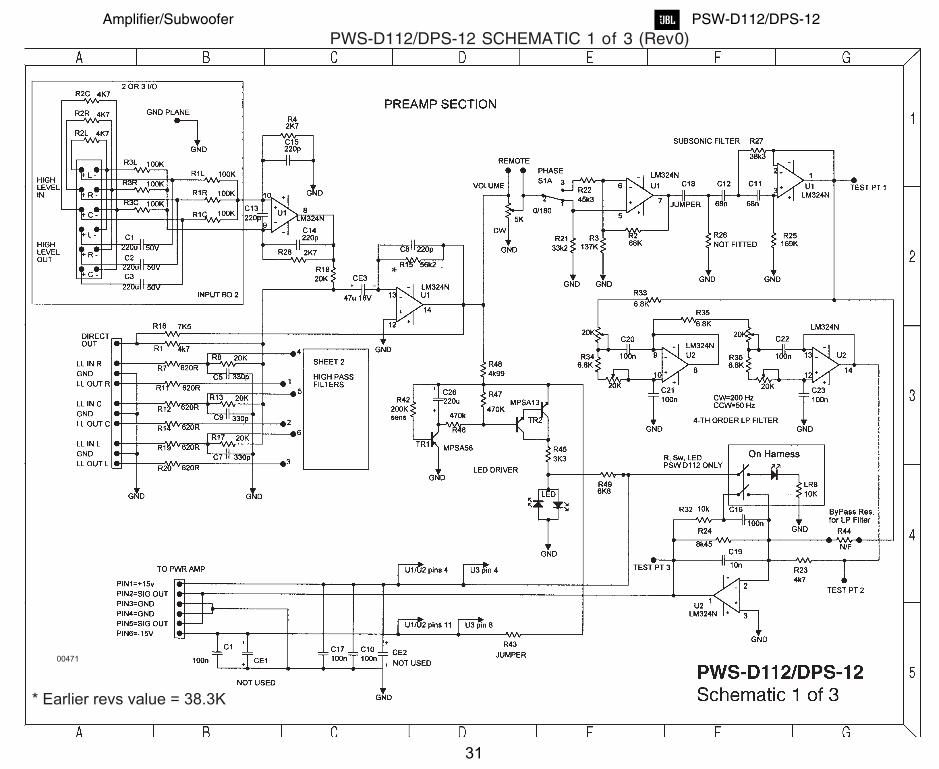
* Earlier revs value = 38.3K
00471
PWS-D112/DPS-12 SCHEMATIC 1 of 3 (Rev0)
31
Amplifier/Subwoofer PSW-D112/DPS-12

PWS-D112/DPS-12 SCHEMATIC 2 of 3 (Rev0)
32
Amplifier/Subwoofer PSW-D112/DPS-12

PWS-D112/DPS-12SCHEMATIC
3of3(Rev0)
*
* Later revs value = 47 ohms
00468
33
Amplifier/Subwoofer PSW-D112/DPS-12

U1
U2 U1
LM324
U1
LM324
R16
38k3
C9
68n
C8
68n
C7
0r JumpR15Not Used
R17169k
R14
68k1
R35137k
R1333k2
R9
2k7C5
220pF
C3 220pF
C2
200uF
C1
200uF
810
9
++
++
--------
++
++
R27
604r
R3420k
R24
604r
R32
20k
R28
20k
C19 330pF
C18 330pF
R10
20kR11
68k
C6
220p
R Out
L Out
R In
GND
L In
R6
R5
R4
R3
100kR82k7
C4
220pF
Phase Switch
SPDT
LEVEL5k LOG
R12
45k3
U2
TLO 64
U2
TLO 64
C17
47nF
C16
47nF
C15
47nF
C14
47nF
High Level In
RCA Connector
High Level Out
R30
604r
R26
604r
R33
20k
R31
20k
1
32
2
3
1
R18
6k8
R20
6k8
U1
20k Lin #1
20k Lin #2
U2
C10
100nF
C12
100nF
C13100nF
C11100nF
R21
Not Used
R196k8
R226k8
R23Not Used
LP DEF
Not Used
20k Lin #3
20k Lin #4
13
12
14
13
1412
3
217
6
5
65
7
8
10
9
13
2
12
3
1
2
3
4
5
6
7
8
9
11
12
10
R1
4k7
R2
4k7
+15V
-15V
C21
100nF
C20
100nF
C23
100nF
C22
100nF
+15V
GND
GND
SIG
-15V
mute
To/F
rom
PW
RA
MP
R25
20k
Control
20K HP POT
20k Lin #1
20K HP POT
20k Lin #2
20K HP POT
20k Lin #3
20K HP POT
20k Lin #4 RC
AC
onne
ctor
++
++
--------
++
++
Vol A
GND
Vol B
ADJ. 2nd Order HI-PASS LINE LEVEL O/P
RemoteVolume Control
CONNECTOR
HI-PASS / EQ
2nd Order LO-PASS 2nd Order LO-PASS
LINE LEVEL
12
J30-R Jumper
1 2
J2NOT USED
1
2
J1
JUMPER
To Pin 4 U1/U2
To Pin 11 U1/U2
PWS-D112/DPS-12SchematicPREAMP Rev1
5 5
4 4
3 3
2 2
1 1
A
A
B
B
C
C
D
D
E
E
F
F
G
G
PWS-D112/DPS-12 PREAMP SCHEMATIC Rev1
34
Amplifier/Subwoofer PSW-D112/DPS-12

BR RECT
RS604
R40
1k
R41
1000k
U1
TL 064 C41
1uF
D121N 5242B
D141N 4148
C42
100uF
R43
1000k
D111N 4148
U1
TL 064
R44100k
R461000k
R4710k
Q1
2N 5457
R48
10k
D13
1N 4148
R49
15k
SigLED 1
2 Col LED
R45
470K
C40
10uF
+6V
V+
V-
+15V
S/D
FR
I/P
GN D
-15V
D6
1N 5234B
C6
100nF
R7B10k
R64R7
D11N 4744A
D2
1N 4744A
C21100N
C22100N
D3
1N 5265B
R310M
O/P
R1A7k5
C32
22uF
U1
TL 064
R34
4k7
4
11 C273n3F
R33
23k7
C2610nF
R32
47k
R31
47k
U1
TL 064
R22
42K2
R23
470kR265k6
R30
10k
R291k2
R281K 2
C20
100nF
C3
470n
R543k2
L2
8.5uH
L1
220uH
C104u7F
C11
330nF
R15
100k
L3
8.5uH
L4
8.5uH
R10B0.1R
R10C0.1R
R10A0.1R
Q10
2N 5401R11
1k
Q11
2N 5401
R13
47k
R14
3k3
R12
1kQ12
2N 3904
CZ
100nF
CW
100nF
SPNeg
SPPos
V+V-
TRX
MCI 4632
CMC
2m2H
C7A100nF
C7B
100nF
R2B7k5
C1
2200uF
C2
2200uF
FUSE
2A SloBloAC Feed
AC Return
9
810
R8A
10k
R8B
10k
R1B7k5
R1C7k5
R2C7k5
R2A7k5
12
1314 R27
10k
4
11
R7A10k
LED 1
LED 2
+15V
GN D
GN D
SIG
-15V
mute
2
31
5
67
R21
4K 7
R42
D7
1N 4148
D8
1N 4148
10k
D101N 5242B
R50
2k2
R100
12k
V+ L ED
4
11
4
11
To U1 Pin 4
To U1 Pin 11
POW ER
SHORT CI RCUI T PROTECT
SI GNA L LED & A UTO MUTE
To/F
rom
PR
EA
MP
MO DUL E
Thermal Brkr
Thermal Breakeron Primary
D4
1N 4148
R433k
R16
NO T USED
D16
NO T USED
OV L O
UV L O
+15
-15
R24
3k3
R25
10k
On Harness
DPDT
0dB
Co
mm
on
-3dB
A/ V
CONNECTO R
On Harness
A V Switc h
SPDT
C24330nF
C25Not Used
R7C10k
R9
Not Used
3x 2W
3x 2W
3x 2W
123
LED
MO L EX 3 PI N
12
3
AV SW
MO L EX 3 PI N
PWS-D112/DPS-12PWRAMP Rev1.0Schematic5 5
4 4
3 3
2 2
1 1
A
A
B
B
C
C
D
D
E
E
F
F
G
G
PWS-D112/DPS-12 POWERAMP SCHEMATIC Rev1.0
35
Amplifier/Subwoofer PSW-D112/DPS-12
BR RECT
RS604
R40
1k
R41
1000k
U1
TL 064 C41
1uF
D121N 5242B
D141N 4148
C42
100uF
R43
1000k
D111N 4148
U1
TL 064
R44100k
R461000k
R4710k
Q1
2N 5457
R48
10k
D13
1N 4148
R49
15k
SigL ED1
2 Col L ED
R45
470K
C40
10uF
+6V
V+
V-
+15V
S/D
FR
I/P
GN D
-15V
D6
1N 5234B
C6
100nF
R7B10k
R64R7
D11N 4744A
D2
1N 4744A
C21100N
C22100N
D3
1N 5265B
R310M
O/P
R1A7k5
C32
22uF
U1
TL 064
R34
4k7
4
11 C273n3F
R33
23k7
C2610nF
R32
47k
R31
47k
U1
TL 064
R22
42K2
R23
470kR265k6
R30
10k
R291k2
R281K 2
C20
100nF
C3
470n
R543k2
L2
8.5uH
L1
220uH
C104u7F
C11
330nF
R15
100k
L3
8.5uH
L4
8.5uH
R10B0.1R
R10C0.1R
R10A0.1R
Q10
2N 5401R11
1k
Q11
2N 5401
R13
47k
R14
3k3
R12
1kQ12
2N 3904
CZ
100nF
CW
100nF
SPNeg
SPPos
V+V-
TRX
MCI 4632
CMC
2m2H
C7A100nF
C7B
100nF
R2B7k5
C1
2200uF
C2
2200uF
FUSE
2A SloBloAC Feed
AC Return
9
810
R8A
10k
R8B
10k
R1B7k5
R1C7k5
R2C7k5
R2A7k5
12
1314 R27
10k
4
11
R7A10k
LED 1
LED 2
+15V
GN D
GN D
SIG
-15V
mute
2
31
5
67
R21
4K 7
R42
D7
1N 4148
D8
1N 4148
10k
D101N 5242B
R50
2k2
R100
12k
V+ L ED
4
11
4
11
To U1 Pi
n 4
To U1 Pi
n 11
POW ER
SHORT CI RCUI T PROTECT
SI GNA L LED & A UTO MUTE
To/F
rom
PR
EA
MP
MO DUL E
Thermal Brkr
Thermal Breakeron Primary
D4
1N 4148
R433k
R16
NO T USED
D16
NO T USED
OV L O
UV L O
+15
-15
R24
3k3
R25
10k
On Harness
DPDT
0dB
Co
mm
on
-3dB
A/ V
CONNECTO R
On Harness
A V Swi
tc h
SPDT
C24330nF
C25Not Used
R7C10k
R9
Not Used
3x 2W
3x 2W
3x 2W
123
LED
MO L EX 3 PI N
12
3
AV SW
MO L EX 3 PI N
PWS-D112/DPS-12SchematicPWRAMP Rev1.15 5
4 4
3 3
2 2
1 1
A
A
B
B
C
C
D
D
E
E
F
F
G
G
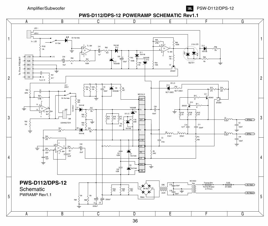
PWS-D112/DPS-12 POWERAMP SCHEMATIC Rev1.1
36
Amplifier/Subwoofer PSW-D112/DPS-12