psz - standard medupi power station project kks key part ... · does not know how to interpret the...
TRANSCRIPT

Document Template 348-24473 Rev 04
PSZ - Standard Medupi Power Station
Project
Title: KKS Key Part Standard
Document Identifier: PSZ 200 - 18202
Alternative Reference Number:
Area of Applicability: Medupi Power Station Project
Functional Area: Configuration Management
Revision: 05
Total Pages: 94
Review Period: 3 Yearly
Disclosure Classification:
Controlled Disclosure
Current Change Note CN 100105

KKS Key Part Standard Unique Identifier: 200-18202
Revision: 05
Page: Page 2 of 94
CONTROLLED DISCLOSURE
When downloaded from the document management system, this document is uncontrolled and the responsibility rests with the user to ensure it is in line with the authorized version on the system.
No part of this document may be reproduced without the expressed consent of the copyright holder, Eskom Holdings SOC Ltd,
Reg. No 2002/015527/30.
Content
Page
1. Introduction ............................................................................................................................... 3
2. Supporting Clauses .................................................................................................................. 3
2.1 Scope ............................................................................................................................... 3
2.1.1 Purpose ................................................................................................................. 3
2.1.2 Applicability ........................................................................................................... 3
2.1.3 Effective date ......................................................................................................... 3
2.2 Normative/Informative References ................................................................................... 3
2.2.1 Normative .............................................................................................................. 3
2.2.2 Informative............................................................................................................. 3
2.3 Definitions ........................................................................................................................ 4
2.4 Abbreviations ................................................................................................................... 4
2.5 Related/Supporting Documents ........................................................................................ 5
3. Process Definition ..................................................................................................................... 5
3.1 General ............................................................................................................................ 5
3.2 Application of KKS ............................................................................................................ 6
3.3 KKS Key Part Contents .................................................................................................... 6
3.3.1 Listing of Alpha Code Elements ............................................................................. 6
3.3.2 Classifying Code Elements .................................................................................... 6
4. Process for Monitoring .............................................................................................................. 7
4.1 Revision Period ................................................................................................................ 7
4.2 Training Requirements ..................................................................................................... 7
5. Acceptance ............................................................................................................................... 7
6. Revisions .................................................................................................................................. 7
7. Development Team .................................................................................................................. 7
Appendix A – KKS Key Part Code Lists .......................................................................................... 8

KKS Key Part Standard Unique Identifier: 200-18202
Revision: 05
Page: Page 3 of 94
CONTROLLED DISCLOSURE
When downloaded from the document management system, this document is uncontrolled and the responsibility rests with the user to ensure it is in line with the authorized version on the system.
No part of this document may be reproduced without the expressed consent of the copyright holder, Eskom Holdings SOC Ltd,
Reg. No 2002/015527/30.
1. Introduction
This document is a Plant Classification system catalogue of KKS codes to be used to classify power plant structures, systems, equipment and components.
2. Supporting Clauses
2.1 Scope
This document serves to provide a list of KKS codes and their descriptions adopted from the VGB
Guidelines, to be applied by the personnel/contractor involved in plant coding executed in Medupi Power station
2.1.1 Purpose
The Purpose of this document is to list and define the contents of KKS Key Parts applicable in
Identification of the plants, systems, equipment and components in Medupi power station
2.1.2 Applicability
This KKS Key Part is applicable to Medupi Power Station Project.
2.1.3 Effective date
Date of authorisation of the document.
2.2 Normative/Informative References
Parties using this document shall apply the most recent edition of the documents listed in the following paragraphs.
2.2.1 Normative
[1] ESKADAAH4 Corporate Directive, KKS Coding of Eskom Power Stations
[2] VGB-B 105 E 7th Edition KKS Key Part, KKS-Identification System for Power Stations, 2010
[3] VGB-B 106 E VGB KKS Application Commentaries, 2004
2.2.2 Informative
[4] 200-4190 The Application of KKS Plant Coding
[5] 200-3340 KKS Coding and Labelling
KKS Key Part Standard Unique Identifier: 200-18202
Revision: 05
Page: Page 4 of 94
CONTROLLED DISCLOSURE
When downloaded from the document management system, this document is uncontrolled and the responsibility rests with the user to ensure it is in line with the authorized version on the system.
No part of this document may be reproduced without the expressed consent of the copyright holder, Eskom Holdings SOC Ltd,
Reg. No 2002/015527/30.
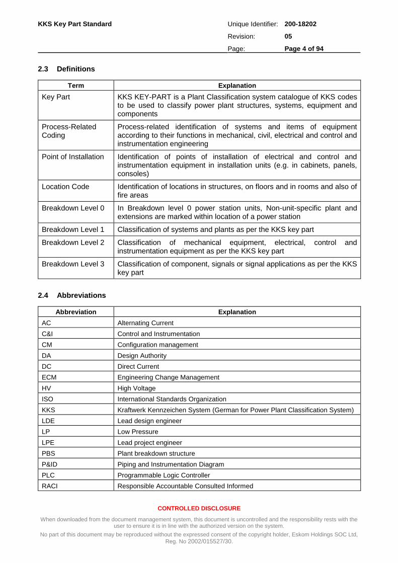
2.3 Definitions
Term Explanation
Key Part KKS KEY-PART is a Plant Classification system catalogue of KKS codes to be used to classify power plant structures, systems, equipment and components
Process-Related Coding
Process-related identification of systems and items of equipment according to their functions in mechanical, civil, electrical and control and instrumentation engineering
Point of Installation Identification of points of installation of electrical and control and instrumentation equipment in installation units (e.g. in cabinets, panels, consoles)
Location Code Identification of locations in structures, on floors and in rooms and also of fire areas
Breakdown Level 0 In Breakdown level 0 power station units, Non-unit-specific plant and extensions are marked within location of a power station
Breakdown Level 1 Classification of systems and plants as per the KKS key part
Breakdown Level 2 Classification of mechanical equipment, electrical, control and instrumentation equipment as per the KKS key part
Breakdown Level 3 Classification of component, signals or signal applications as per the KKS key part
2.4 Abbreviations
Abbreviation Explanation
AC Alternating Current
C&I Control and Instrumentation
CM Configuration management
DA Design Authority
DC Direct Current
ECM Engineering Change Management
HV High Voltage
ISO International Standards Organization
KKS Kraftwerk Kennzeichen System (German for Power Plant Classification System)
LDE Lead design engineer
LP Low Pressure
LPE Lead project engineer
PBS Plant breakdown structure
P&ID Piping and Instrumentation Diagram
PLC Programmable Logic Controller
RACI Responsible Accountable Consulted Informed

KKS Key Part Standard Unique Identifier: 200-18202
Revision: 05
Page: Page 5 of 94
CONTROLLED DISCLOSURE
When downloaded from the document management system, this document is uncontrolled and the responsibility rests with the user to ensure it is in line with the authorized version on the system.
No part of this document may be reproduced without the expressed consent of the copyright holder, Eskom Holdings SOC Ltd,
Reg. No 2002/015527/30.
Abbreviation Explanation
SPO Smart Plant Owner Operator
UPS Uninterruptible Power Supply
VGB Technische Vereinigung Der Grosskraftwerksbetreiber (German for Society of Large Power Station Operators)
2.5 Related/Supporting Documents
Documents superseded by this procedure
[1] 200-18202 Medupi KKS Key Part Standard Rev 04
Records
[2] KKS Management Database
[3] PBS in SPO
3. Process Definition
3.1 General
KKS KEY-PART is a Plant Classification system catalogue of KKS codes to be used to classify power plant structures, systems, equipment and components. The Key part has been compiled as a comprehensive list of classification codes to use but provision is made through this procedure, should the need arise to add to the key part.
a) The design authority and/or the CM technician responsible for the application of the KKS codes may only use codes which appear in this KKS key-part.
b) If for any reason, a code cannot be found and a change to this document is required, it should follow the Eskom Change Management Procedure (200-5664)
c) Identify need for updating of key part document. The need for a change/update could arise from any of the following reasons:
Errors could have been made with the compilation of the existing key part.
New technology that is not provided for in the key part needs to be incorporated.
Discrepancies between supplier and Eskom key parts may exist.
New updates from the VGB could lead to an update to the Eskom key part.
d) Discuss the requested changes with the role players. These will normally be the requestor, the Plant Lead Engineer and KKS consultant.
e) The Consultant will propose a solution to the requested change. The solution could be:
Deal with the requested change within the existing codes. It is possible that the requester does not know how to interpret the KKS key part and a satisfactorily solution can be found without changing the Key part.
Incorporate new codes, change or add to key-part.
Issue a new revision of the key part.

KKS Key Part Standard Unique Identifier: 200-18202
Revision: 05
Page: Page 6 of 94
CONTROLLED DISCLOSURE
When downloaded from the document management system, this document is uncontrolled and the responsibility rests with the user to ensure it is in line with the authorized version on the system.
No part of this document may be reproduced without the expressed consent of the copyright holder, Eskom Holdings SOC Ltd,
Reg. No 2002/015527/30.
3.2 Application of KKS
For the format, structure and specific application rules of the Key Part codes, refer to NMP 45-7. (200-4190).
3.3 KKS Key Part Contents
3.3.1 Listing of Alpha Code Elements
The alpha code elements F1, F2, F3, A1, A2 and B1, B2 have a classifying function, and a full listing of these codes is given in Error! Reference source not found..
3.3.2 Classifying Code Elements
The classifying coding letters and designations are listed in the KKS Coding keys as follows:
a) Function key for F1/F1 F2 /F1 F2 F3 on breakdown level 1.
b) Equipment unit code key for A1/A1 A2 on breakdown level 2.
c) Component code key for B1/B1 B2 on breakdown level 3.
For an explanation of the data characters G, F0, FN, AN, A3 and BN, please refer to Error! eference source not found..
Serial No. of breakdown level
0 1 2 3
Designation of data character
G F0 F1 F2 F3 FN A1 A2 AN A3 B1 B2 BN
Type of data character
A or N
N
A A A
N N
A A
N N N
(A)
A A
N N
Main groups F1
Groups F2
Subgroups F3
Main groups A1
Subgroups A2
Main groups B1
Subgroups B2

KKS Key Part Standard Unique Identifier: 200-18202
Revision: 05
Page: Page 7 of 94
CONTROLLED DISCLOSURE
When downloaded from the document management system, this document is uncontrolled and the responsibility rests with the user to ensure it is in line with the authorized version on the system.
No part of this document may be reproduced without the expressed consent of the copyright holder, Eskom Holdings SOC Ltd,
Reg. No 2002/015527/30.
4. Process for Monitoring
4.1 Revision Period
All QMS documents shall undergo a 3-yearly compulsory revision.
4.2 Training Requirements
The Contractor shall be responsible for ensuring that he is fully familiar with the standards and concepts of the KKS system as applied by ESKOM.
5. Acceptance
This document has been seen and accepted by:
Name Designation
Chuma Mketo CM Line Manager
Renier Smal KKS Consultant
Graham Makoni Project Manager
Xola Gubuza CM Snr Technician
Mduduzi Dhlamini CM Snr Technician
6. Revisions
Date Rev. Compiler Remarks
January 2018 05 L Cingo Updated to include SGM and SNJ
Populated the scope and the purpose
Aligned document with the new template
December 2014 04 R Smal Changed the document from a procedure to a standard to conform to the Medupi QA requirements.
Removed RACI, KPA/KPI’s and self-assessment.
October 2014 03 R Smal Changed the document template to conform to the Medupi QMS Template PTZ 200-65191 Rev 2
7. Development Team
The following people were involved in the development of this document:
Lihle Cingo
Chuma Mketo

Medupi KKS Key Part Standard Unique Identifier: 200-18202
Revision: 05
Page: Page 8 of 94
CONTROLLED DISCLOSURE
When downloaded from the document management system, this document is uncontrolled and the responsibility rests with the user to ensure it is in line with the authorized version on the system.
No part of this document may be reproduced without the expressed consent of the copyright holder, Eskom Holdings SOC Ltd,
Reg. No 2002/015527/30.
Appendix A – KKS Key Part Code Lists
A.1 A- Grid and Distribution System
A GRID AND DISTRIBUTION SYSTEM Rev
AB > 430 kV SYSTEM
ABA 431 - 765 kV System
ABB > 766 kV System
AC 276 - 430 kV SYSTEM
ACA 276 - 400 kV System
ACB 401 - 430 kV System
ACT 276 - 430 kV Transformer
AD 166 - 275 kV SYSTEM
ADA 166 - 220 kV System
ADB 221 - 275 kV System
AE 89 - 165 kV SYSTEM
AEA 89 - 132 kV System
AEB 133 - 165 kV System
AF 51 - 88 kV SYSTEM
AFA 51 - 66 kV System
AFB 67 - 88 kV System
AG 36 - 50 kV SYSTEM
AGA 36 - 42 kV System
AGB 43 - 50 kV System
AH 26 - 35 kV SYSTEM
AHA 26 - 33 kV System
AHB 34 - 35 kV System
AJ 17 - 25 kV SYSTEM
AJA 17 - 18 kV System
AJB 19 - 20 kV System
AJC 21 - 25 kV System
AK 6.7 - 16 kV SYSTEM
AKA 6.7 - 10.5 kV System
AKB 10.6 - 16 kV System
AL 3.4 - 6.6 kV SYSTEM
ALA 3.4 - 6.6 kV System
AM 1 - 3.3 kV SYSTEM
AMA 1 - 2.2 kV System
AMB 2.3 - 3.3 kV System
AN < 1 kV SYSTEM
ANA Low Voltage Switchgear 500 V - 1 kV AC
ANB Low Voltage Switchgear 500 V - 1 kV AC

Medupi KKS Key Part Standard Unique Identifier: 200-18202
Revision: 05
Page: Page 9 of 94
CONTROLLED DISCLOSURE
When downloaded from the document management system, this document is uncontrolled and the responsibility rests with the user to ensure it is in line with the authorized version on the system.
No part of this document may be reproduced without the expressed consent of the copyright holder, Eskom Holdings SOC Ltd,
Reg. No 2002/015527/30.
A GRID AND DISTRIBUTION SYSTEM Rev
ANC Low Voltage Switchgear 500 V - 1 kV AC
ANE Low Voltage Switchgear 220/380 V AC
ANF Low Voltage Switchgear 220/380 V AC
ANG Low Voltage Switchgear 110 V AC
ANH Low Voltage Switchgear 110 V AC
ANK DC Switchgear 110/220 V
ANL DC Switchgear 110/220 V
ANM DC Switchgear 110/220 V
ANN DC Switchgear 110/220 V
ANQ DC Switchgear 48/60 V
ANR DC Switchgear 48/60 V
ANS DC Switchgear 48/60 V
ANU DC Switchgear 12/24 V
ANV DC Switchgear 12/24 V
ANW DC Switchgear 12/24 V
AC Three-single/phase alternating current
AP CONTROL DESK
APA Control Desk 2
AQ MEASURING AND METERING EQUIPMENT
AQA Measurement Panel 400 kV
AQB Measurement Panel 275 kV
AQC Measurement Panel 132 kV
AQD Measurement Panel 765 kV
AQE Measurement Panel 88 kV
AR PROTECTION EQUIPMENT
ARA Protection Panel
ARB Bus-zone Protection Panel
AS DECENTRALIZED PANELS AND CUBICLES (FIELD EQUIPMENT)
ASA Circuit Breaker Accessory
ASB Multiplication, Conversion, Decoupling
ASC Converter Accessory
ASD Compressed Air, Hydraulic
ASJ Automated Control, Closed Loop Control
ASL Grid Simulation and Voltage Group Selection
ASM Measuring
ASN Auxiliary Power Supply
ASP Recording
ASQ Metering
ASR Protection
ASS Synchronizing
AST Transforming

Medupi KKS Key Part Standard Unique Identifier: 200-18202
Revision: 05
Page: Page 10 of 94
CONTROLLED DISCLOSURE
When downloaded from the document management system, this document is uncontrolled and the responsibility rests with the user to ensure it is in line with the authorized version on the system.
No part of this document may be reproduced without the expressed consent of the copyright holder, Eskom Holdings SOC Ltd,
Reg. No 2002/015527/30.
A GRID AND DISTRIBUTION SYSTEM Rev
ASU Panels and Cubicles for Auxiliary Equipment
ASV Group Intermediate and General Terminal Block
ASW Indication, Supervision, Operation and Equipment
ASX Alarm Annunciation
AT TRANSFORMER EQUIPMENT
ATA Transformer > 400 kV
AU CONTROL EQUIPMENT FOR OPEN LOOP CONTROL, FEEDBACK INDICATION AND AUXILIARY EQUIPMENT
AUA System Control and Load Despatch (SCALD)
AUB Control Desk in Control Room
AUC Control Panel in Control Room
AUD PLC (Programmable logic Controller)
AUE Local Control Panel and Desk
AUF Equipment Room Cubicle
AUG Junction Box
AUH Measurement Rack
AUJ Spare
AUK DC Supply Including Associate Equipment
AUL AC Supply and Distribution
AUQ Computer Equipment
AUW Common Equipment
AUX Common Equipment
AV MARSHALLING RACK (KIOSK)
AVA Intermediate Distribution Frame
AW INSTRUMENT PANEL
AWA Instrument Panel 2
AX CENTRALIZED EQUIPMENT (e.g. PROCESS COMPUTER, HV YARD BUILDING)
AXB Annunciator in HV Yard (Alarm Panel)
AXD PLC (Programmable Logic Controller)
AY TELECOMMUNICATION EQUIPMENT
AYA Telephone System (PAX/PABX)
AYB Telephone Control Console (Intercom System Repeater and Base Station)
AYC Loudspeaker System (Tone Alarm Public Address)
AYD Visual Signal System
AYE Fire Alarm System
AYF Clock System
AYG Remote Supervisory System
AYH Telemetering System
AYJ Remote Metering System
AYK HF Carrier Telephone System
AYL Staff Paging System, Wireless

Medupi KKS Key Part Standard Unique Identifier: 200-18202
Revision: 05
Page: Page 11 of 94
CONTROLLED DISCLOSURE
When downloaded from the document management system, this document is uncontrolled and the responsibility rests with the user to ensure it is in line with the authorized version on the system.
No part of this document may be reproduced without the expressed consent of the copyright holder, Eskom Holdings SOC Ltd,
Reg. No 2002/015527/30.
A GRID AND DISTRIBUTION SYSTEM Rev
AYM Staff Paging System, Inductive
AYN Staff Paging System, Hardwired
AYP TV Supervisory Control System
AYQ GAS alarm systems
AYS Radio Network (VHF, UHF, SHF)

Medupi KKS Key Part Standard Unique Identifier: 200-18202
Revision: 05
Page: Page 12 of 94
CONTROLLED DISCLOSURE
When downloaded from the document management system, this document is uncontrolled and the responsibility rests with the user to ensure it is in line with the authorized version on the system.
No part of this document may be reproduced without the expressed consent of the copyright holder, Eskom Holdings SOC Ltd,
Reg. No 2002/015527/30.
A.2 Power Station Electrical Power System
B POWER STATION ELECTRICAL POWER SYSTEM Rev
BA GENERATOR POWER EXPORT SYSTEM
BAA Generator Busbar System
From: Excl. Generator bushings but including busbar plus flexible connections, instrument and excitation transformers, surge arresters, pressurizing and cooling system
To: Excl. Generator transformer and auxiliary (unit) transformer bushings
BAB Generator Foundation
BAC Circuit-breaker (Generator breaker and phase reversing isolator) incl. Cooling and Compressed Air System
BAT Generator Transformer, Incl. Cooling System
BAW Generator Earthing and Lightning Protection System
BAX Control Air Supply
BAY Closed/Open Loop Control and Protection Equipment
BB MEDIUM VOLTAGE AUXILIARY POWER SYSTEM (≥ 11 kV)
BBA Medium Voltage Distribution System
BBB Medium Voltage Distribution System
BBC Medium Voltage Distribution System
BBD Medium Voltage Distribution System
BBE Medium Voltage Distribution System
BBF Medium Voltage Distribution System
BBG Medium Voltage Distribution System
BBH Medium Voltage Distribution System
BBJ Medium Voltage Distribution System
BBK Medium Voltage Distribution System
BBL Medium Voltage Distribution System
BBM Medium Voltage Distribution System
BBN Medium Voltage Distribution System
BBP Medium Voltage Distribution System
BBQ Medium Voltage Distribution System
BBR Medium Voltage Distribution System
BBS Medium Voltage Distribution System
BBT Medium Voltage Transformer
BBX Control Medium Supply for Closed/Open Loop Control and Protection Equipment
BBY Closed/Open Loop Control and Protection Equipment
BC MEDIUM VOLTAGE AUXILIARY POWER SYSTEM (6.6 - < 11 kV)
BCA Medium Voltage Distribution System
BCB Medium Voltage Distribution System
BCC Medium Voltage Distribution System
BCD Medium Voltage Distribution System
BCE Medium Voltage Distribution System

Medupi KKS Key Part Standard Unique Identifier: 200-18202
Revision: 05
Page: Page 13 of 94
CONTROLLED DISCLOSURE
When downloaded from the document management system, this document is uncontrolled and the responsibility rests with the user to ensure it is in line with the authorized version on the system.
No part of this document may be reproduced without the expressed consent of the copyright holder, Eskom Holdings SOC Ltd,
Reg. No 2002/015527/30.
B POWER STATION ELECTRICAL POWER SYSTEM Rev
BCF Medium Voltage Distribution System
BCG Medium Voltage Distribution System
BCH Medium Voltage Distribution System
BCJ Medium Voltage Distribution System
BCK Medium Voltage Distribution System
BCL Medium Voltage Distribution System
BCM Medium Voltage Distribution System
BCN Medium Voltage Distribution System
BCP Medium Voltage Distribution System
BCQ Medium Voltage Distribution System
BCR Medium Voltage Distribution System
BCS Medium Voltage Distribution System
BCT Medium Voltage Transformer
BCX Control Medium Supply for Closed/Open Loop Control and Protection Equipment
BCY Closed/Open Loop Control and Protection Equipment
BD MEDIUM VOLTAGE AUXILIARY POWER SYSTEM (3.3 - < 6.6 kV)
BDA Medium Voltage Distribution System
BDB Medium Voltage Distribution System
BDC Medium Voltage Distribution System
BDD Medium Voltage Distribution System
BDE Medium Voltage Distribution System
BDF Medium Voltage Distribution System
BDG Medium Voltage Distribution System
BDH Medium Voltage Distribution System
BDJ Medium Voltage Distribution System
BDK Medium Voltage Distribution System
BDL Medium Voltage Distribution System
BDM Medium Voltage Distribution System
BDN Medium Voltage Distribution System
BDP Medium Voltage Distribution System
BDQ Medium Voltage Distribution System
BDR Medium Voltage Distribution System
BDS Medium Voltage Distribution System
BDT Medium Voltage Transformer
BDX Control Medium Supply for Closed/Open Loop Control and Protection Equipment
BDY Closed/Open Loop Control and Protection Equipment
BF LOW VOLTAGE AUXILIARY POWER SYSTEM 1
BFA Low Voltage Distribution System
BFB Low Voltage Distribution System
BFC Low Voltage Distribution System
BFD Low Voltage Distribution System

Medupi KKS Key Part Standard Unique Identifier: 200-18202
Revision: 05
Page: Page 14 of 94
CONTROLLED DISCLOSURE
When downloaded from the document management system, this document is uncontrolled and the responsibility rests with the user to ensure it is in line with the authorized version on the system.
No part of this document may be reproduced without the expressed consent of the copyright holder, Eskom Holdings SOC Ltd,
Reg. No 2002/015527/30.
B POWER STATION ELECTRICAL POWER SYSTEM Rev
BFE Low Voltage Distribution System
BFF Low Voltage Distribution System
BFG Low Voltage Distribution System
BFH Low Voltage Distribution System
BFJ Low Voltage Distribution System
BFK Low Voltage Distribution System
BFL Low Voltage Distribution System
BFM Low Voltage Distribution System
BFN Low Voltage Distribution System
BFP Low Voltage Distribution System
BFQ Low Voltage Distribution System
BFR Low Voltage Distribution System
BFS Low Voltage Distribution System
BFT Low Voltage Transformer
BFU Low Voltage Transformer
BFV Low Voltage Transformer
BFW Low Voltage Transformer
BFY Closed/Open Loop Control and Protection Equipment
BH LOW VOLTAGE AUXILIARY POWER SYSTEM 2
BHA Low Voltage Distribution System
BHB Low Voltage Distribution System
BHC Low Voltage Distribution System
BHD Low Voltage Distribution System
BHE Low Voltage Distribution System
BHF Low Voltage Distribution System
BHG Low Voltage Distribution System
BHH Low Voltage Distribution System
BHJ Low Voltage Distribution System
BHK Low Voltage Distribution System
BHL Low Voltage Distribution System
BHM Low Voltage Distribution System
BHN Low Voltage Distribution System
BHP Low Voltage Distribution System
BHQ Low Voltage Distribution System
BHR Low Voltage Distribution System
BHS Low Voltage Distribution System
BHT Low Voltage Transformer
BHU Low Voltage Transformer
BHV Low Voltage Transformer
BHW Low Voltage Transformer
BHY Closed/Open Loop Control and Protection Equipment

Medupi KKS Key Part Standard Unique Identifier: 200-18202
Revision: 05
Page: Page 15 of 94
CONTROLLED DISCLOSURE
When downloaded from the document management system, this document is uncontrolled and the responsibility rests with the user to ensure it is in line with the authorized version on the system.
No part of this document may be reproduced without the expressed consent of the copyright holder, Eskom Holdings SOC Ltd,
Reg. No 2002/015527/30.
B POWER STATION ELECTRICAL POWER SYSTEM Rev
BJ LOW VOLTAGE AUXILIARY POWER SYSTEM 3
BJA Low Voltage Distribution System
BJB Low Voltage Distribution System
BJC Low Voltage Distribution System
BJD Low Voltage Distribution System
BJE Low Voltage Distribution System
BJF Low Voltage Distribution System
BJG Low Voltage Distribution System
BJH Low Voltage Distribution System
BJJ Low Voltage Distribution System
BJK Low Voltage Distribution System
BJL Low Voltage Distribution System
BJM Low Voltage Distribution System
BJN Low Voltage Distribution System
BJP Low Voltage Distribution System
BJQ Low Voltage Distribution System
BJR Low Voltage Distribution System
BJS Low Voltage Distribution System
BJT Low Voltage Transformer
BJY Closed/Open Loop Control and Protection Equipment
BL LOW VOLTAGE AUXILIARY POWER SYSTEM (LIGHTING)
BLA Low Voltage Distribution System (Lighting)
BLB Low Voltage Distribution System (Lighting)
BLC Low Voltage Distribution System (Lighting)
BLD Low Voltage Distribution System (Lighting)
BLE Low Voltage Distribution System (Lighting)
BLF Low Voltage Distribution System (Lighting)
BLG Low Voltage Distribution System (Lighting)
BLH Low Voltage Distribution System (Lighting)
BLJ Low Voltage Distribution System (Lighting)
BLK Low Voltage Distribution System (Lighting)
BLL Low Voltage Distribution System (Lighting)
BLM Low Voltage Distribution System (Lighting)
BLN Low Voltage Distribution System (Lighting)
BLP Low Voltage Distribution System (Lighting)
BLQ Low Voltage Distribution System (Lighting)
BLR Low Voltage Distribution System (Lighting)
BLS Low Voltage Distribution System (Lighting)
BLT Low Voltage Transformer (Lighting)
BLY Closed/Open Loop Control and Protection Equipment
BM EMERGENCY LOW VOLTAGE AUXILIARY POWER SYSTEM 1 (Diesel Generator Supply)

Medupi KKS Key Part Standard Unique Identifier: 200-18202
Revision: 05
Page: Page 16 of 94
CONTROLLED DISCLOSURE
When downloaded from the document management system, this document is uncontrolled and the responsibility rests with the user to ensure it is in line with the authorized version on the system.
No part of this document may be reproduced without the expressed consent of the copyright holder, Eskom Holdings SOC Ltd,
Reg. No 2002/015527/30.
B POWER STATION ELECTRICAL POWER SYSTEM Rev
BMA Emergency Low Voltage Distribution System
BMB Emergency Low Voltage Distribution System
BMC Emergency Low Voltage Distribution System
BMD Emergency Low Voltage Distribution System
BME Emergency Low Voltage Distribution System
BMF Emergency Low Voltage Distribution System
BMG Emergency Low Voltage Distribution System
BMH Emergency Low Voltage Distribution System
BMJ Emergency Low Voltage Distribution System
BMK Emergency Low Voltage Distribution System
BML Emergency Low Voltage Distribution System
BMM Emergency Low Voltage Distribution System
BMN Emergency Low Voltage Distribution System
BMP Emergency Low Voltage Distribution System
BMQ Emergency Low Voltage Distribution System
BMR Emergency Low Voltage Distribution System
BMS Emergency Low Voltage Distribution System
BMT Emergency Low Voltage Transformer
BMU Emergency Low Voltage Transformer
BMV Emergency Low Voltage Transformer
BMW Emergency Low Voltage Transformer
BMY Closed/Open Loop Control and Protection Equipment
BN EMERGENCY LOW VOLTAGE AUXILIARY POWER SYSTEM 2
BNA Emergency Low Voltage Distribution System
BNB Emergency Low Voltage Distribution System
BNC Emergency Low Voltage Distribution System
BND Emergency Low Voltage Distribution System
BNE Emergency Low Voltage Distribution System
BNF Emergency Low Voltage Distribution System
BNG Emergency Low Voltage Distribution System
BNH Emergency Low Voltage Distribution System
BNJ Emergency Low Voltage Distribution System
BNK Emergency Low Voltage Distribution System
BNL Emergency Low Voltage Distribution System
BNM Emergency Low Voltage Distribution System
BNN Emergency Low Voltage Distribution System
BNP Emergency Low Voltage Distribution System
BNQ Emergency Low Voltage Distribution System
BNR Emergency Low Voltage Distribution System
BNS Emergency Low Voltage Distribution System
BNT Emergency Low Voltage Transformer

Medupi KKS Key Part Standard Unique Identifier: 200-18202
Revision: 05
Page: Page 17 of 94
CONTROLLED DISCLOSURE
When downloaded from the document management system, this document is uncontrolled and the responsibility rests with the user to ensure it is in line with the authorized version on the system.
No part of this document may be reproduced without the expressed consent of the copyright holder, Eskom Holdings SOC Ltd,
Reg. No 2002/015527/30.
B POWER STATION ELECTRICAL POWER SYSTEM Rev
BNU Emergency Low Voltage Transformer
BNV Emergency Low Voltage Transformer
BNW Emergency Low Voltage Transformer
BNY Closed/Open Loop Control and Protection Equipment
BP HEAVY CURRENT EQUIPMENT FOR LARGE VARIABLE SPEED DRIVES
(Frequency converter system, e.g. for feedwater pumps excl. equipment, not power adjusters in switchgear)
BPA Heavy current equipment for variable speed drive on boiler feed pump
BPB Heavy current equipment for variable speed drive on coal plant
BPC Heavy current equipment for variable speed drive on ash plant
BPD Heavy current equipment for variable speed drive on main cooling plant
BPE Heavy current equipment for variable speed drive in LP services
BPF Heavy current equipment for large variable speed drive frequency converter for large blower systems
BR LOW VOLTAGE AUXILIARY POWER SYSTEM (CONVERTER, INVERTER)
BRA Low Voltage Distribution System (Converter, Inverter)
BRB Low Voltage Distribution System (Converter, Inverter)
BRC Low Voltage Distribution System (Converter, Inverter)
BRD Low Voltage Distribution System (Converter, Inverter)
BRE Low Voltage Distribution System (Converter, Inverter)
BRF Low Voltage Distribution System (Converter, Inverter)
BRG Low Voltage Distribution System (Converter, Inverter)
BRH Low Voltage Distribution System (Converter, Inverter)
BRJ Low Voltage Distribution System (Converter, Inverter)
BRK Low Voltage Distribution System (Converter, Inverter)
BRL Low Voltage Distribution System (Converter, Inverter)
BRM Low Voltage Distribution System (Converter, Inverter)
BRN Low Voltage Distribution System (Converter, Inverter)
BRP Low Voltage Distribution System (Converter, Inverter)
BRQ Low Voltage Distribution System (Converter, Inverter)
BRR Low Voltage Distribution System (Converter, Inverter)
BRS Low Voltage Distribution System (UPS)
BRT Converter (Rotating)
BRU Converter (Static), Inverter
BRV Emergency Power Generation Equipment (If not under X-heavy machine)
BRY Closed/Open Loop Control and Protection Equipment
BT DC GENERATION EQUIPMENT (BATTERY AND CHARGER)
BTA Battery
BTB Battery
BTC Battery
BTD Battery
BTE Battery

Medupi KKS Key Part Standard Unique Identifier: 200-18202
Revision: 05
Page: Page 18 of 94
CONTROLLED DISCLOSURE
When downloaded from the document management system, this document is uncontrolled and the responsibility rests with the user to ensure it is in line with the authorized version on the system.
No part of this document may be reproduced without the expressed consent of the copyright holder, Eskom Holdings SOC Ltd,
Reg. No 2002/015527/30.
B POWER STATION ELECTRICAL POWER SYSTEM Rev
BTF Battery
BTG Battery
BTH Battery
BTJ Battery
BTK Battery
BTL Battery Charger
BTM Battery Charger
BTN Battery Charger
BTP Battery Charger
BTQ Battery Charger
BTR Battery Charger
BTS Battery Charger
BTT Battery Charger
BTU Battery Charger
BTV Battery Charger
BTW Uninterruptible Power Supply
BTX Common Equipment
BTY Common Equipment
BTZ Common Equipment
BU DC DISTRIBUTION SYSTEM
BUA DC Distribution System
BUB DC Distribution System
BUC DC Distribution System
BUD DC Distribution System
BUE DC Distribution System
BUF DC Distribution System
BUG DC Distribution System
BUH DC Distribution System
BUJ DC Distribution System
BUK DC Distribution System
BUL DC Distribution System
BUM DC Distribution System
BUN DC Distribution System
BUP DC Distribution System
BUQ DC Distribution System
BUR DC Distribution System
BUS DC Distribution System
BUY Closed/Open Loop Control and Protection Equipment
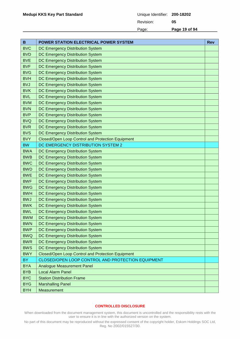
BV DC EMERGENCY DISTRIBUTION SYSTEM 1
BVA DC Emergency Distribution System
BVB DC Emergency Distribution System
Medupi KKS Key Part Standard Unique Identifier: 200-18202
Revision: 05
Page: Page 19 of 94
CONTROLLED DISCLOSURE
When downloaded from the document management system, this document is uncontrolled and the responsibility rests with the user to ensure it is in line with the authorized version on the system.
No part of this document may be reproduced without the expressed consent of the copyright holder, Eskom Holdings SOC Ltd,
Reg. No 2002/015527/30.
B POWER STATION ELECTRICAL POWER SYSTEM Rev
BVC DC Emergency Distribution System
BVD DC Emergency Distribution System
BVE DC Emergency Distribution System
BVF DC Emergency Distribution System
BVG DC Emergency Distribution System
BVH DC Emergency Distribution System
BVJ DC Emergency Distribution System
BVK DC Emergency Distribution System
BVL DC Emergency Distribution System
BVM DC Emergency Distribution System
BVN DC Emergency Distribution System
BVP DC Emergency Distribution System
BVQ DC Emergency Distribution System
BVR DC Emergency Distribution System
BVS DC Emergency Distribution System
BVY Closed/Open Loop Control and Protection Equipment
BW DC EMERGENCY DISTRIBUTION SYSTEM 2
BWA DC Emergency Distribution System
BWB DC Emergency Distribution System
BWC DC Emergency Distribution System
BWD DC Emergency Distribution System
BWE DC Emergency Distribution System
BWF DC Emergency Distribution System
BWG DC Emergency Distribution System
BWH DC Emergency Distribution System
BWJ DC Emergency Distribution System
BWK DC Emergency Distribution System
BWL DC Emergency Distribution System
BWM DC Emergency Distribution System
BWN DC Emergency Distribution System
BWP DC Emergency Distribution System
BWQ DC Emergency Distribution System
BWR DC Emergency Distribution System
BWS DC Emergency Distribution System
BWY Closed/Open Loop Control and Protection Equipment
BY CLOSED/OPEN LOOP CONTROL AND PROTECTION EQUIPMENT
BYA Analogue Measurement Panel
BYB Local Alarm Panel
BYC Station Distribution Frame
BYG Marshalling Panel
BYH Measurement
Medupi KKS Key Part Standard Unique Identifier: 200-18202
Revision: 05
Page: Page 20 of 94
CONTROLLED DISCLOSURE
When downloaded from the document management system, this document is uncontrolled and the responsibility rests with the user to ensure it is in line with the authorized version on the system.
No part of this document may be reproduced without the expressed consent of the copyright holder, Eskom Holdings SOC Ltd,
Reg. No 2002/015527/30.
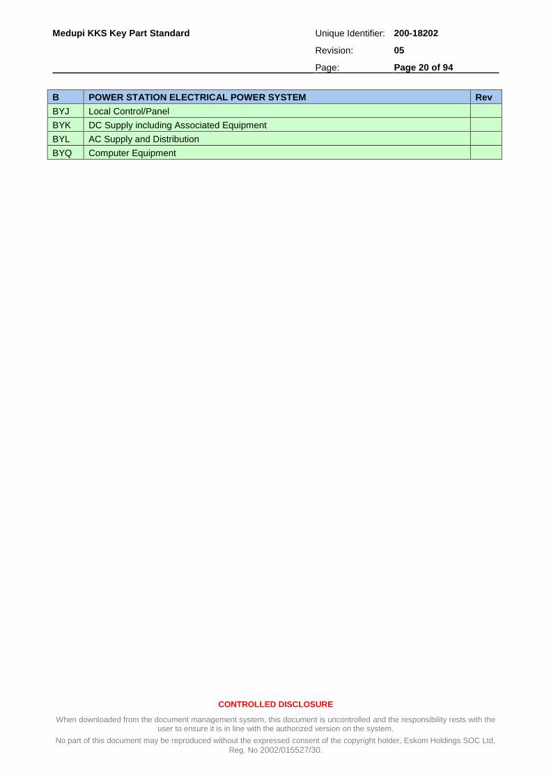
B POWER STATION ELECTRICAL POWER SYSTEM Rev
BYJ Local Control/Panel
BYK DC Supply including Associated Equipment
BYL AC Supply and Distribution
BYQ Computer Equipment

Medupi KKS Key Part Standard Unique Identifier: 200-18202
Revision: 05
Page: Page 21 of 94
CONTROLLED DISCLOSURE
When downloaded from the document management system, this document is uncontrolled and the responsibility rests with the user to ensure it is in line with the authorized version on the system.
No part of this document may be reproduced without the expressed consent of the copyright holder, Eskom Holdings SOC Ltd,
Reg. No 2002/015527/30.
A.3 C – Control and Instrumentation Equipment
C CONTROL AND INSTRUMENTATION EQUIPMENT Rev
CA PROTECTION INTERLOCKING
CAA Protection Interlocking Cabinet A
CAB Protection Interlocking Cabinet B
CAC Protection Interlocking Cabinet C
CAD Protection Interlocking Cabinet D
CAE Protection Interlocking Cabinet E
CAF Protection Interlocking Cabinet F
CAG Protection Interlocking Cabinet G
CAH Protection Interlocking Cabinet H
CAJ Protection Interlocking Cabinet J
CAK Protection Interlocking Cabinet K
CAL Protection Interlocking Cabinet L
CAM Protection Interlocking Cabinet M
CAN Protection Interlocking Cabinet N
CAP Protection Interlocking Cabinet P
CAQ Protection Interlocking Cabinet Q
CB FUNCTIONAL GROUP CONTROL, PARTIAL CONTROL
CBA Functional Group Control Cabinet A
CBB Functional Group Control Cabinet B
CBC Functional Group Control Cabinet C
CBD Functional Group Control Cabinet D
CBE Functional Group Control Cabinet E
CBF Functional Group Control Cabinet F
CBG Functional Group Control Cabinet G
CBH Functional Group Control Cabinet H
CBJ Functional Group Control Cabinet J
CBK Functional Group Control Cabinet K
CBL Functional Group Control Cabinet L
CBM Functional Group Control Cabinet M
CBN Functional Group Control Cabinet N
CBP Synchronizing Cabinet
CBQ Auxiliary Power Supply Changeover System Cabinet
CC BINARY SIGNAL CONDITIONING
CCA Binary Signal Conditioning Cabinet A
CCB Binary Signal Conditioning Cabinet B
CCC Binary Signal Conditioning Cabinet C
CCD Binary Signal Conditioning Cabinet D
CCE Binary Signal Conditioning Cabinet E
CCF Binary Signal Conditioning Cabinet F
CCG Binary Signal Conditioning Cabinet G
Medupi KKS Key Part Standard Unique Identifier: 200-18202
Revision: 05
Page: Page 22 of 94
CONTROLLED DISCLOSURE
When downloaded from the document management system, this document is uncontrolled and the responsibility rests with the user to ensure it is in line with the authorized version on the system.
No part of this document may be reproduced without the expressed consent of the copyright holder, Eskom Holdings SOC Ltd,
Reg. No 2002/015527/30.
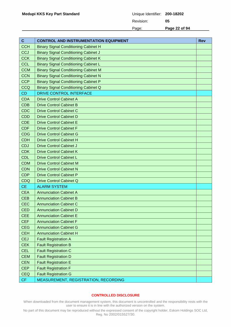
C CONTROL AND INSTRUMENTATION EQUIPMENT Rev
CCH Binary Signal Conditioning Cabinet H
CCJ Binary Signal Conditioning Cabinet J
CCK Binary Signal Conditioning Cabinet K
CCL Binary Signal Conditioning Cabinet L
CCM Binary Signal Conditioning Cabinet M
CCN Binary Signal Conditioning Cabinet N
CCP Binary Signal Conditioning Cabinet P
CCQ Binary Signal Conditioning Cabinet Q
CD DRIVE CONTROL INTERFACE
CDA Drive Control Cabinet A
CDB Drive Control Cabinet B
CDC Drive Control Cabinet C
CDD Drive Control Cabinet D
CDE Drive Control Cabinet E
CDF Drive Control Cabinet F
CDG Drive Control Cabinet G
CDH Drive Control Cabinet H
CDJ Drive Control Cabinet J
CDK Drive Control Cabinet K
CDL Drive Control Cabinet L
CDM Drive Control Cabinet M
CDN Drive Control Cabinet N
CDP Drive Control Cabinet P
CDQ Drive Control Cabinet Q
CE ALARM SYSTEM
CEA Annunciation Cabinet A
CEB Annunciation Cabinet B
CEC Annunciation Cabinet C
CED Annunciation Cabinet D
CEE Annunciation Cabinet E
CEF Annunciation Cabinet F
CEG Annunciation Cabinet G
CEH Annunciation Cabinet H
CEJ Fault Registration A
CEK Fault Registration B
CEL Fault Registration C
CEM Fault Registration D
CEN Fault Registration E
CEP Fault Registration F
CEQ Fault Registration G
CF MEASUREMENT, REGISTRATION, RECORDING

Medupi KKS Key Part Standard Unique Identifier: 200-18202
Revision: 05
Page: Page 23 of 94
CONTROLLED DISCLOSURE
When downloaded from the document management system, this document is uncontrolled and the responsibility rests with the user to ensure it is in line with the authorized version on the system.
No part of this document may be reproduced without the expressed consent of the copyright holder, Eskom Holdings SOC Ltd,
Reg. No 2002/015527/30.
C CONTROL AND INSTRUMENTATION EQUIPMENT Rev
CFA Measurement Cabinet A
CFB Measurement Cabinet B
CFC Measurement Cabinet C
CFD Measurement Cabinet D
CFE Measurement Cabinet E
CFF Measurement Cabinet F
CFL Radiation Measurement Cabinet A
CFM Radiation Measurement Cabinet B
CFN Radiation Measurement Cabinet C
CFP Radiation Measurement Cabinet D
CFQ Registration Recording Cabinet (Counter, Printer, etc.)
CG CLOSED LOOP CONTROL (EXCLUDING POWER PART/CORRECTING UNIT)
CGA HP Bypass Control Cubicle
CGB Closed Loop Control Cabinet B
CGC Closed Loop Control Cabinet C
CGD Closed Loop Control Cabinet D
CGE Closed Loop Control Cabinet E
CGF Closed Loop Control Cabinet F
CGG Closed Loop Control Cabinet G
CGH Closed Loop Control Cabinet H
CH PROTECTION (EXCEPT REACTOR PROTECTION)
CHA Generator Protection Cabinet A
CHB Generator Protection Cabinet B
CHC Generator Protection Cabinet C
CHD Generator Protection Cabinet D
CHE Mechanical Equipment Protection Cabinet A
CHF Mechanical Equipment Protection Cabinet B
CHG Mechanical Equipment Protection Cabinet C
CHH Mechanical Equipment Protection Cabinet D
CHJ Mechanical Equipment Protection Cabinet E
CHK Mechanical Equipment Protection Cabinet F
CHL Mechanical Equipment Protection Cabinet G
CHM Mechanical Equipment Protection Cabinet H
CHN Mechanical Equipment Protection Cabinet J
CHP Mechanical Equipment Protection Cabinet K
CHQ Mechanical Equipment Protection Cabinet L
CHR Mechanical Equipment Protection Cabinet M
CHS Mechanical Equipment Protection Cabinet N
CHT Mechanical Equipment Protection Cabinet P
CHU Mechanical Equipment Protection Cabinet Q
CHV Mechanical Equipment Protection Cabinet R

Medupi KKS Key Part Standard Unique Identifier: 200-18202
Revision: 05
Page: Page 24 of 94
CONTROLLED DISCLOSURE
When downloaded from the document management system, this document is uncontrolled and the responsibility rests with the user to ensure it is in line with the authorized version on the system.
No part of this document may be reproduced without the expressed consent of the copyright holder, Eskom Holdings SOC Ltd,
Reg. No 2002/015527/30.
C CONTROL AND INSTRUMENTATION EQUIPMENT Rev
CHW Mechanical Equipment Protection Cabinet S
CHX Mechanical Equipment Protection Cabinet T
CHY Mechanical Equipment Protection Cabinet U
CJ UNIT COORDINATION LEVEL
CJA Unit Coordination System (Including Cabinet)
CJD Start-up Control, Set Point Formation (Unit Related) (Including cabinet)
CJF Boiler Master Control System (Including Cabinet)
CJJ Steam Turbine Set Master Control Cabinet A
CJK Steam Turbine Set Master Control Cabinet B
CJL Steam Turbine Set Master Control Cabinet C
CJM Steam Turbine Set Master Control Cabinet D
CJN Steam Turbine Set Master Control Cabinet E
CJU Main and Large Machine Master Control Cabinet A
CJV Main and Large Machine Master Control Cabinet B
CJW Main and Large Machine Master Control Cabinet C
CJX Main and Large Machine Master Control Cabinet D
CJY Main and Large Machine Master Control Cabinet E
CK PROCESS COMPUTER SYSTEM
CKA Monitoring Computer
CKB Active Control Computer
CKC Energy Summation Computer
CKD Supervisory Computer
CKE Status Display Computer A
CKF Status Display Computer B
CKG Status Display Computer C
CKH Status Display Computer D
CKJ Access Control Computer A
CKK Access Control Computer B
CKL Access Control Computer C
CKM Access Control Computer D
CKN Access Control Computer E
CKP Access Control Computer F
CKQ Access Control Computer G
CKR Access Control Computer H
CKS Access Control Computer J
CKT Access Control Computer K
CKU Access Control Computer L
CKV Access Control Computer M
CKW Access Control Computer N
CKX Access Control Computer P
CKY Access Control Computer Q

Medupi KKS Key Part Standard Unique Identifier: 200-18202
Revision: 05
Page: Page 25 of 94
CONTROLLED DISCLOSURE
When downloaded from the document management system, this document is uncontrolled and the responsibility rests with the user to ensure it is in line with the authorized version on the system.
No part of this document may be reproduced without the expressed consent of the copyright holder, Eskom Holdings SOC Ltd,
Reg. No 2002/015527/30.
C CONTROL AND INSTRUMENTATION EQUIPMENT Rev
CKZ Training Simulator
CM INSTRUMENT AND CONTROL EQUIPMENT 2
CMA Instrumentation and control equipment 2
CMB Instrumentation and control equipment 2
CMC Instrumentation and control equipment 2
CME Instrumentation and control equipment 2
CN INSTRUMENT AND CONTROL EQUIPMENT 2
CNA Instrumentation and control equipment 2
CNB Instrumentation and control equipment 2
CNC Instrumentation and control equipment 2
CND Instrumentation and control equipment 2
CP SEPARATE AUTOMATION SYSTEM 2
CPB Separate automation system 2
CPE Separate automation system 2
CQ INSTRUMENT AND CONTROL EQUIPMENT 2
CQA Instrumentation and control equipment 2
CQB Instrumentation and control equipment 2
CQD Instrumentation and control equipment 2
CQE Instrumentation and control equipment 2
CQF Instrumentation and control equipment 2
CQG Instrumentation and control equipment 2
CQH Instrumentation and control equipment 2
CQJ Instrumentation and control equipment 2
CR GROUP CONTROL CUBICLE (ONLY TO BE USED WHEN ‘CB’ IS FULL)
CRA Group Control Cubicle
CRB Group Control Cubicle
CRC Group Control Cubicle
CRD Group Control Cubicle
CRE Group Control Cubicle
CRF Group Control Cubicle
CRX Group Control Cubicle
CRY Group Control Cubicle
CS SYSTEM COMBINATIONS
CSA Automation System Cabinet A
CSB Automation System Cabinet B
CSC Automation System Cabinet C
CSD Automation System Cabinet D
CSE Automation System Cabinet E
CSF Automation System Cabinet F
CSG Automation System Cabinet G
CSH Automation System Cabinet H

Medupi KKS Key Part Standard Unique Identifier: 200-18202
Revision: 05
Page: Page 26 of 94
CONTROLLED DISCLOSURE
When downloaded from the document management system, this document is uncontrolled and the responsibility rests with the user to ensure it is in line with the authorized version on the system.
No part of this document may be reproduced without the expressed consent of the copyright holder, Eskom Holdings SOC Ltd,
Reg. No 2002/015527/30.
C CONTROL AND INSTRUMENTATION EQUIPMENT Rev
CSJ Automation System Cabinet J
CSK Automation System Cabinet K
CSL Automation System Cabinet L
CSM Automation System Cabinet M
CSN Automation System Cabinet N
CT RELAY CUBICLE FOR BINARY DRIVES
CTE Interposing Relay Cubicle for Binary Drives
CTV 220 V Distribution Cubicle
CU CLOSED LOOP CONTROL (POWER PART/CORRECTING UNIT)
CUA Cabinet for Closed Loop Control (Power Parts) A
CUB Cabinet for Closed Loop Control (Power Parts) B
CUC Cabinet for Closed Loop Control (Power Parts) C
CUD Cabinet for Closed Loop Control (Power Parts) D
CUE Cabinet for Closed Loop Control (Power Parts) E
CUF Cabinet for Closed Loop Control (Power Parts) F
CUG Cabinet for Closed Loop Control (Power Parts) G
CUH Cabinet for Closed Loop Control (Power Parts) H
CUJ Cabinet for Closed Loop Control (Power Parts) J
CUK Cabinet for Closed Loop Control (Power Parts) K
CUL Cabinet for Closed Loop Control (Power Parts) L
CUM Cabinet for Closed Loop Control (Power Parts) M
CUN Cabinet for Closed Loop Control (Power Parts) N
CUP Cabinet for Closed Loop Control (Power Parts) P
CUQ Cabinet for Closed Loop Control (Power Parts) Q
CV MARSHALLING RACK AND SIGNAL - DISTRIBUTION FRAME
CVA Distribution Frame (UDF and SDF)
CVB Distribution Frame (MDF)
CVC Uninterruptible Power Supply Distribution Frame
CVD Control interface box
CVE Control interface box
CVF Control interface box
CVG Control interface box
CVP Main C&I Marshalling Cubicle
CW CONTROL ROOM
CWA Main Control Desk A
CWB Main Control Desk B
CWC Main Control Desk C
CWD Main Control Desk D
CWE Main Control Desk E
CWF Main Control Panel A
CWG Main Control Panel B
Medupi KKS Key Part Standard Unique Identifier: 200-18202
Revision: 05
Page: Page 27 of 94
CONTROLLED DISCLOSURE
When downloaded from the document management system, this document is uncontrolled and the responsibility rests with the user to ensure it is in line with the authorized version on the system.
No part of this document may be reproduced without the expressed consent of the copyright holder, Eskom Holdings SOC Ltd,
Reg. No 2002/015527/30.
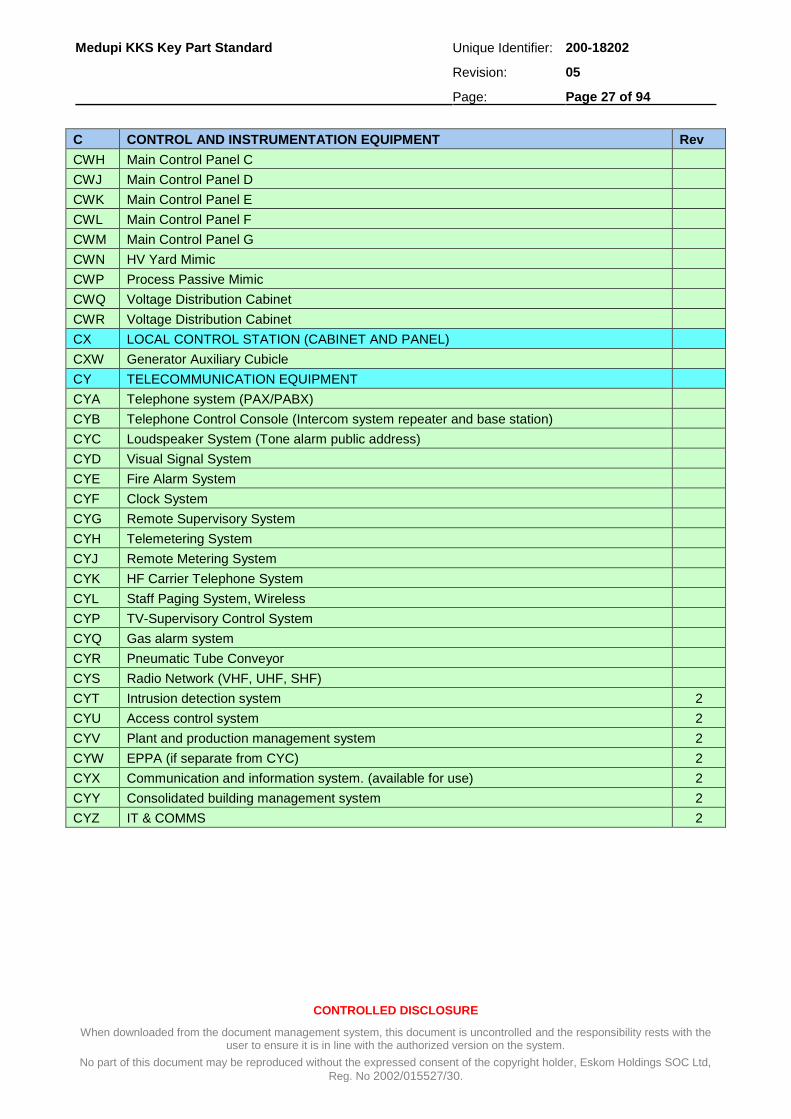
C CONTROL AND INSTRUMENTATION EQUIPMENT Rev
CWH Main Control Panel C
CWJ Main Control Panel D
CWK Main Control Panel E
CWL Main Control Panel F
CWM Main Control Panel G
CWN HV Yard Mimic
CWP Process Passive Mimic
CWQ Voltage Distribution Cabinet
CWR Voltage Distribution Cabinet
CX LOCAL CONTROL STATION (CABINET AND PANEL)
CXW Generator Auxiliary Cubicle
CY TELECOMMUNICATION EQUIPMENT
CYA Telephone system (PAX/PABX)
CYB Telephone Control Console (Intercom system repeater and base station)
CYC Loudspeaker System (Tone alarm public address)
CYD Visual Signal System
CYE Fire Alarm System
CYF Clock System
CYG Remote Supervisory System
CYH Telemetering System
CYJ Remote Metering System
CYK HF Carrier Telephone System
CYL Staff Paging System, Wireless
CYP TV-Supervisory Control System
CYQ Gas alarm system
CYR Pneumatic Tube Conveyor
CYS Radio Network (VHF, UHF, SHF)
CYT Intrusion detection system 2
CYU Access control system 2
CYV Plant and production management system 2
CYW EPPA (if separate from CYC) 2
CYX Communication and information system. (available for use) 2
CYY Consolidated building management system 2
CYZ IT & COMMS 2

Medupi KKS Key Part Standard Unique Identifier: 200-18202
Revision: 05
Page: Page 28 of 94
CONTROLLED DISCLOSURE
When downloaded from the document management system, this document is uncontrolled and the responsibility rests with the user to ensure it is in line with the authorized version on the system.
No part of this document may be reproduced without the expressed consent of the copyright holder, Eskom Holdings SOC Ltd,
Reg. No 2002/015527/30.
A.4 E – Conventional Fuel Supply and Residue Disposal
E CONVENTIONAL FUEL SUPPLY AND RESIDUE DISPOSAL Rev
EA COAL UNLOADING AND STORAGE
EAA Ship unloading system
From Incl. unloading equipment
To Excl. transport storage system
EAB Wagon and truck unloading
From Incl. unloading equipment
To Excl. transport storage system
EAC Transport System
From Incl. reception point
To Excl. storage (stockpile) Incl. internal transport system within coal unloading and storage areas
To Excl. outlet
EAD Stacking, reclaiming equipment
From Excl. transport system
To Excl. storage system (stockpile)
EAE Storage area (stockpile)
From Excl. stacking, reclaiming system
To Excl. transport stacking, reclaiming system
EAF Excavation system, return loading system
From Excl. bunker system storage area
To Excl. transport system
EAT Weighing equipment (mass meter)
EAU Sampling equipment
EAX Control medium supply for closed/open loop control and protection equipment
EAY Closed/open loop control and protection equipment
EB MECHANICAL COAL TREATMENT (COAL CRUSHING, MIXING DRYING) BEFORE STATION RECEPTION POINT
EBA Transport system
From Incl. receiving point
To Excl. transfer point to treatment mixing system
EBB Mixing system
From Incl. receiving point
To Excl. transfer point to another system
EBC Crushing System
From Incl. receiving point
To Excl. transfer point of another system
EBD Screening System
From Incl. receiving point
To Excl. transfer point of another system
EBE Separator system and associated removal equipment - if not constructive part of one of the

Medupi KKS Key Part Standard Unique Identifier: 200-18202
Revision: 05
Page: Page 29 of 94
CONTROLLED DISCLOSURE
When downloaded from the document management system, this document is uncontrolled and the responsibility rests with the user to ensure it is in line with the authorized version on the system.
No part of this document may be reproduced without the expressed consent of the copyright holder, Eskom Holdings SOC Ltd,
Reg. No 2002/015527/30.
E CONVENTIONAL FUEL SUPPLY AND RESIDUE DISPOSAL Rev
previous systems (EBA to EBD)
From Incl. receiving point
To Excl. transfer point of another system
EBR Residue removal
EBT Weighing equipment (mass meter)
EBU Sampling equipment
EBX Control medium supply for closed/open loop control and protection equipment
EBY Closed/open loop control and protection equipment
EC COAL DISTRIBUTION AND UNIT (INTERMEDIATE) STORAGE SYSTEM
ECA Transport system
From Excl. coal unloading and storage system
To Excl. unit (intermediate) storage system (silos/staithes)
ECB Transport system (Conveyors to mill bins)
From Excl. unit (intermediate) storage system (silos/staithes)
To Excl. bunker for pulverizing system
ECE Unit (intermediate) storage system (silos/staithes)
From Excl. transport system
To Excl. transport system (conveyors to mill bins)
ECT Weighing equipment (mass meter)
ECU Sampling equipment
ECX Control medium supply for closed/open loop control and protection equipment
ECY Closed/open loop control and protection equipment
EG OIL SUPPLY (APPLICABLE TO ESKOM LIGHTING-UP OIL SYSTEM)
EGA Handing over point equipment including long distance pipeline
From Excl. reception point
To Excl. tank Incl. handing over pumping units
EGB Storage tank system
From Incl. inlet of storage tank
To Incl. outlet of storage tank
EGC Pumping system
From Incl. pump suction flange
To Incl. pump discharge flange
EGD Piping system
From Excl. tank outlet
To Excl. intermediate oil tank respective individual consumers (Burners)
EGR Residue removal system
EGT Heating medium system (Steam system)
From Excl. branch of supply system
To Incl. consumer and
From Excl. consumers
To Excl. inlet into another system

Medupi KKS Key Part Standard Unique Identifier: 200-18202
Revision: 05
Page: Page 30 of 94
CONTROLLED DISCLOSURE
When downloaded from the document management system, this document is uncontrolled and the responsibility rests with the user to ensure it is in line with the authorized version on the system.
No part of this document may be reproduced without the expressed consent of the copyright holder, Eskom Holdings SOC Ltd,
Reg. No 2002/015527/30.
E CONVENTIONAL FUEL SUPPLY AND RESIDUE DISPOSAL Rev
EGX Control medium supply for closed/open loop control and protection equipment
EGY Closed/open loop control and protection equipment
EK GAS SUPPLY (APPLICABLE TO ESKOM LIGHTING-UP GAS SYSTEM)
EKA Gas pipe system equipment including long distance pipeline
From Excl. offloading point
To Incl. inlet of another system
EKB Liquid separation
From Incl. Liquid separation inlet
To Incl. liquid separation outlet
EKC Heating system
From Incl. heating inlet
To Incl. heating outlet
EKD Pressure reducing station (Expansion turbine)
From Incl. pressure reducing station inlet
To Incl. pressure reducing station outlet
EKE Mechanical purification, gas scrubbing
From Incl. inlet mechanical purification gas scrubbing
To Incl. outlet mechanical purification gas scrubbing
EKF Storage tank system (Cylinders)
from Incl. storage tank inlet
To Incl. storage tank outlet
EKG Piping system
From Excl. storage system
To Excl. supply to customers
EKH Main pressure increasing equipment
From Incl. pump suction flange
To Incl. pump discharge flange
EKR Residue separation
EKT Heating medium system
From Excl. diversion supply system
To Excl. consumer and
From Excl. consumer
To Excl. feed into another system
EKX Control medium supply for closed/open loop control and protection equipment
EKY Closed/open loop control and protection equipment
EN OTHER FUEL SUPPLY (USE ONLY FOR COMBINATIONS OF DIFFERENT FUEL TYPES
ENA Diesel fuel oil storage
From Incl. storage tank inlet
To Incl. storage tank outlet
END Diesel fuel oil piping system
From Excl. off-loading point

Medupi KKS Key Part Standard Unique Identifier: 200-18202
Revision: 05
Page: Page 31 of 94
CONTROLLED DISCLOSURE
When downloaded from the document management system, this document is uncontrolled and the responsibility rests with the user to ensure it is in line with the authorized version on the system.
No part of this document may be reproduced without the expressed consent of the copyright holder, Eskom Holdings SOC Ltd,
Reg. No 2002/015527/30.
E CONVENTIONAL FUEL SUPPLY AND RESIDUE DISPOSAL Rev
To Incl. inlet of another system
ENG Diesel fuel oil pumping system
From Incl. pump suction flange
To Incl. pump discharge flange
ENX Control medium supply of closed/open loop control and protection equipment
ER LIGHTING-UP FUEL SUPPLY
ERA Pulverized coal supply system
From Excl. reception point
To Excl. coal burners or
To Excl. other consumers
ERB Oil supply system (for Eskom see EG system)
From Excl. reception point
To Excl. oil burners or
To Excl. other consumers
ERC Gas supply system (for Eskom see EK system)
From Excl. reception point
To Excl. gas burners or
To Excl. other consumers
ERX Control medium supply for closed/open loop control and protection equipment
ERY Closed/open loop control and protection equipment
ET ASH AND SLAG REMOVAL SYSTEM (FROM EXCLUDING REMOVAL EQUIPMENT)
ETA Wet ash conveying system
From Excl. transport equipment (submerged scraper conveyor) or
From Excl. reception point
To Excl. storage area or
To Excl. transport point of another system (transverse conveyor)
ETB Wet ash settling pond and storage system
From Excl. reception point
To Incl. transport equipment
ETC Wet ash extraction system
From Excl. reception point
To Excl. transfer point of another system
ETD Granulate conveying system (coarse ash)
From Excl. transport equipment
To Excl. storage tank or
To Excl. transfer point of another system
ETE Granulate storage system (coarse ash)
From Excl. reception point
To Incl. transport equipment
ETG Dry ash conveying system
From Excl. transport equipment (e.g. precipitator outlet)

Medupi KKS Key Part Standard Unique Identifier: 200-18202
Revision: 05
Page: Page 32 of 94
CONTROLLED DISCLOSURE
When downloaded from the document management system, this document is uncontrolled and the responsibility rests with the user to ensure it is in line with the authorized version on the system.
No part of this document may be reproduced without the expressed consent of the copyright holder, Eskom Holdings SOC Ltd,
Reg. No 2002/015527/30.
E CONVENTIONAL FUEL SUPPLY AND RESIDUE DISPOSAL Rev
To Excl. storage system or
To Excl. transfer point of another system
ETH Dry ash storage system (Fly ash bunker)
From Excl. reception point
To Excl. transport equipment (ash conditioners)
ETK Wet and dry ash common conveying system
From Excl. reception point
To Excl. storage area or
To Excl. transfer point of another system
ETL Wet and dry ash common storage system (Ash dump, ash dam)
From Excl. reception point
To Incl. storage point
ETM Wet and dry ash settling system
From Excl. reception point conveying machinery
To Excl. pit or
To Excl. transfer point of another system
ETN Scavenge water transport, distribution and recovery for flushing and ash water
From Excl. inlet or
From Incl. diversion
To Excl. inlet into another system
ETP Generation and distribution of conveying/aeration air
From Excl. diversion or
From Incl. compressor plant
To Excl. inlet into conveying system
ETS Stacking, Spreading system
From Excl. transport system
From Excl. storage system (ash dump)
ETV Lubricant supply system 2
ETX Control medium supply for closed/open loop control and protection equipment
ETY Closed/open loop control and protection equipment
EU TREATMENT AND TRANSPORT SYSTEM FOR COMBUSTION, FUEL TREATMENT, FUEL CONVERTING, FUEL GAS CLEANING RESIDUE
EUA Treatment system for residue of fuel treatment
From Incl. inlet
To Incl. outlet
EUB Treatment system for residue of fuel converting
From Incl. inlet
To Incl. outlet
EUC Treatment system for residue of fuel combustion
From Incl. inlet
To Incl. outlet

Medupi KKS Key Part Standard Unique Identifier: 200-18202
Revision: 05
Page: Page 33 of 94
CONTROLLED DISCLOSURE
When downloaded from the document management system, this document is uncontrolled and the responsibility rests with the user to ensure it is in line with the authorized version on the system.
No part of this document may be reproduced without the expressed consent of the copyright holder, Eskom Holdings SOC Ltd,
Reg. No 2002/015527/30.
E CONVENTIONAL FUEL SUPPLY AND RESIDUE DISPOSAL Rev
EUD Treatment system for residue of fuel gas purification
From Incl. Inlet
To Incl. outlet
EUX Control medium supply for closed/open loop control and protection equipment
EUY Closed/open loop control and protection equipment.
EY CLOSED/OPEN LOOP CONTROL AND PROTECTION EQUIPMENT
EYA Control Desk in Control Room
EYB Control Panel in Control Room
EYC Local Control Panel Desk and Solenoid Operated Valve Panel
EYD Spare
EYE Spare
EYF Spare
EYG Marshaling Panel
EYH Measurement Rack
EYJ VSD Field equipment panels 2
EYK DC Supply including Associated Equipment
EYL AC Supply a Distribution
EYQ Computer Equipment

KKS Key Part Standard Unique Identifier: 200-18202
Revision: 05
Page: Page 34 of 94
CONTROLLED DISCLOSURE
When downloaded from the document management system, this document is uncontrolled and the responsibility rests with the user to ensure it is in line with the authorized version on the system.
No part of this document may be reproduced without the expressed consent of the copyright holder, Eskom Holdings SOC Ltd,
Reg. No 2002/015527/30.
A.5 G – Water Supply and Discharge
G WATER SUPPLY AND DISCHARGE Rev
GA RAW WATER SUPPLY SYSTEM
GAA Supply system, mechanical
From Incl. inlet screen
To Incl. outlet screen
GAC Piping and channel system
From Excl. extraction point or
From Excl. outlet of another system
To Excl. inlet into another system
GAD Storage equipment
From Incl. storage system inlet
To Incl. storage system outlet
GAF Pumping system
From Incl. pump suction flange
To Incl. pump discharge flange
GAV Lubrication medium supply
GAX Control medium supply for closed/open loop control and protection equipment
GAY Closed/open loop control and protection equipment
GB TREATMENT (DECARBONIZATION) INCL. COOLING TOWER MAKE-UP WATER TREATMENT
GBB Filtering, mechanical purification
From Incl. inlet to purification equipment
To Incl. outlet of purification equipment
GBC Ventilation, gas injection
From Excl. atmosphere or
From Incl. gas supply
To Excl. inlet to another system
GBD Precipitation (e.g. decarbonization, flocculation)
From Incl. precipitation inlet
To Incl. precipitation outlet
GBE Acid dosing (e.g. decarbonization)
From Incl. acid dosing equipment or
From Excl. chemical supply branch
To Excl. inlet of another system
GBF Ion exchanger (e.g. desalination)
From Incl. ion exchanger system inlet and
From Incl. chemical supply isolating valve, auxiliary medium supply to ion exchanger
To Incl. ion exchanger system outlet

KKS Key Part Standard Unique Identifier: 200-18202
Revision: 05
Page: Page 35 of 94
CONTROLLED DISCLOSURE
When downloaded from the document management system, this document is uncontrolled and the responsibility rests with the user to ensure it is in line with the authorized version on the system.
No part of this document may be reproduced without the expressed consent of the copyright holder, Eskom Holdings SOC Ltd,
Reg. No 2002/015527/30.
GBG Evaporation (e.g. desalination)
From Incl. feedwater inlet
To Incl. steam outlet and
From Incl. hot steam inlet
To Incl. condensate outlet
GBH Degasification, drying
From Incl. degasifier tank inlet
To Incl. tank outlet Incl. heating equipment steam condenser
GBJ Preheating, cooling
From Incl. heater or cooler inlet
To Incl. heater or cooler outlet
GBK Internal piping, intermediate storage, pump system for main medium internal piping
From Excl. extraction point or outlet of another system
To Excl. inlet of another system
To Incl. medium treatment outlet
Intermediate storage:
From Incl. inlet, intermediate storage
To Incl. outlet, intermediate storage
Pump system:
From Incl. suction flange, pumping system
To Incl. discharge flange, pumping system
GBL Storage outside medium handling (if not part of another system)
From Incl. storage plant inlet
To Incl. storage plant outlet
GBN Chemical supply system
From Incl. intake or
From Incl. storage tank
To Excl. transfer of another system
GBP Regeneration and purging equipment
From Incl. system inlet
To Excl. injection to another system
From Excl. chemical supply, auxiliary medium supply and purging air supply
To Incl. regeneration purging equipment
GBQ Injection device for main medium (e.g. hardness stabilization)
From Incl. injection device or
From Excl. chemical supply junction
To Incl. inlet into another system
GBR Flushing water and residue removal incl. neutralization
From Excl. outlet of the respective system
KKS Key Part Standard Unique Identifier: 200-18202
Revision: 05
Page: Page 36 of 94
CONTROLLED DISCLOSURE
When downloaded from the document management system, this document is uncontrolled and the responsibility rests with the user to ensure it is in line with the authorized version on the system.
No part of this document may be reproduced without the expressed consent of the copyright holder, Eskom Holdings SOC Ltd,
Reg. No 2002/015527/30.
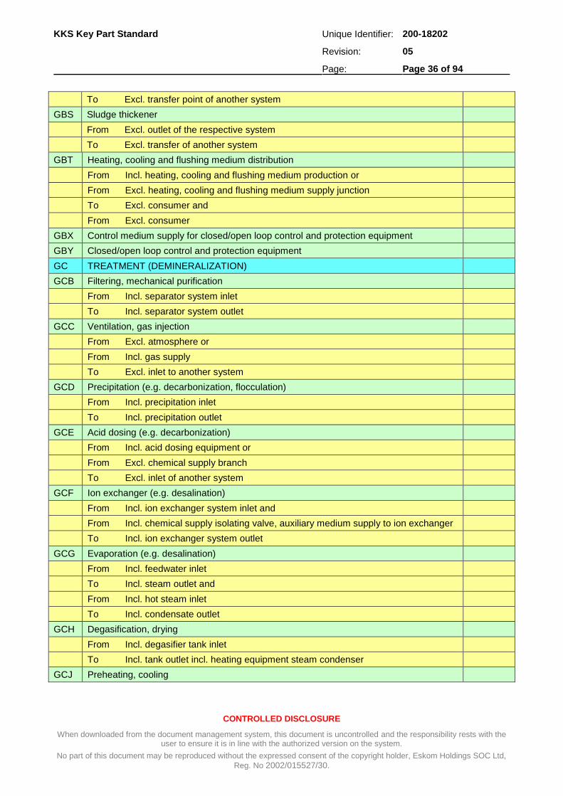
To Excl. transfer point of another system
GBS Sludge thickener
From Excl. outlet of the respective system
To Excl. transfer of another system
GBT Heating, cooling and flushing medium distribution
From Incl. heating, cooling and flushing medium production or
From Excl. heating, cooling and flushing medium supply junction
To Excl. consumer and
From Excl. consumer
GBX Control medium supply for closed/open loop control and protection equipment
GBY Closed/open loop control and protection equipment
GC TREATMENT (DEMINERALIZATION)
GCB Filtering, mechanical purification
From Incl. separator system inlet
To Incl. separator system outlet
GCC Ventilation, gas injection
From Excl. atmosphere or
From Incl. gas supply
To Excl. inlet to another system
GCD Precipitation (e.g. decarbonization, flocculation)
From Incl. precipitation inlet
To Incl. precipitation outlet
GCE Acid dosing (e.g. decarbonization)
From Incl. acid dosing equipment or
From Excl. chemical supply branch
To Excl. inlet of another system
GCF Ion exchanger (e.g. desalination)
From Incl. ion exchanger system inlet and
From Incl. chemical supply isolating valve, auxiliary medium supply to ion exchanger
To Incl. ion exchanger system outlet
GCG Evaporation (e.g. desalination)
From Incl. feedwater inlet
To Incl. steam outlet and
From Incl. hot steam inlet
To Incl. condensate outlet
GCH Degasification, drying
From Incl. degasifier tank inlet
To Incl. tank outlet incl. heating equipment steam condenser
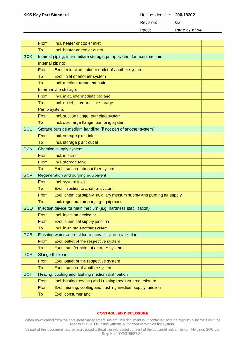
GCJ Preheating, cooling
KKS Key Part Standard Unique Identifier: 200-18202
Revision: 05
Page: Page 37 of 94
CONTROLLED DISCLOSURE
When downloaded from the document management system, this document is uncontrolled and the responsibility rests with the user to ensure it is in line with the authorized version on the system.
No part of this document may be reproduced without the expressed consent of the copyright holder, Eskom Holdings SOC Ltd,
Reg. No 2002/015527/30.
From Incl. heater or cooler inlet
To Incl. heater or cooler outlet
GCK Internal piping, intermediate storage, pump system for main medium
Internal piping:
From Excl. extraction point or outlet of another system
To Excl. inlet of another system
To Incl. medium treatment outlet
Intermediate storage:
From Incl. inlet, intermediate storage
To Incl. outlet, intermediate storage
Pump system:
From Incl. suction flange, pumping system
To Incl. discharge flange, pumping system
GCL Storage outside medium handling (if not part of another system)
From Incl. storage plant inlet
To Incl. storage plant outlet
GCN Chemical supply system
From Incl. intake or
From Incl. storage tank
To Excl. transfer into another system
GCP Regeneration and purging equipment
From Incl. system inlet
To Excl. injection to another system
From Excl. chemical supply, auxiliary medium supply and purging air supply
To Incl. regeneration purging equipment
GCQ Injection device for main medium (e.g. hardness stabilization)
From Incl. injection device or
From Excl. chemical supply junction
To Incl. inlet into another system
GCR Flushing water and residue removal incl. neutralization
From Excl. outlet of the respective system
To Excl. transfer point of another system
GCS Sludge thickener
From Excl. outlet of the respective system
To Excl. transfer of another system
GCT Heating, cooling and flushing medium distribution
From Incl. heating, cooling and flushing medium production or
From Excl. heating, cooling and flushing medium supply junction
To Excl. consumer and

KKS Key Part Standard Unique Identifier: 200-18202
Revision: 05
Page: Page 38 of 94
CONTROLLED DISCLOSURE
When downloaded from the document management system, this document is uncontrolled and the responsibility rests with the user to ensure it is in line with the authorized version on the system.
No part of this document may be reproduced without the expressed consent of the copyright holder, Eskom Holdings SOC Ltd,
Reg. No 2002/015527/30.
From Excl. consumer
GCX Control medium supply for closed/open loop control and protection equipment
GCY Closed/open loop control and protection equipment
GD TREATMENT SYSTEM (OTHERS) 1
GDB Filtering, mechanical purification
From Incl. separator system inlet
To Incl. separator system outlet
GDC Ventilation, gas injection
From Excl. atmosphere or
From Incl. gas supply
To Excl. inlet to another system
GDD Precipitation (e.g. decarbonization, flocculation)
From Incl. precipitation inlet
To Incl. precipitation outlet
GDE Acid dosing (e.g. decarbonization)
From Incl. acid dosing equipment or
From Excl. chemical supply branch
To Excl. inlet of another system
GDF Ion exchanger (e.g. desalination)
From Incl. ion exchanger system inlet and
From Incl. chemical supply isolating valve, auxiliary medium supply to ion exchanger
To Incl. ion exchanger system outlet
GDG Evaporation (e.g. desalination)
From Incl. feedwater inlet
To Incl. steam outlet and
From Incl. hot steam inlet
To Incl. condensate outlet
GDH Degasification, drying
From Incl. degasifier tank inlet
To Incl. tank outlet incl. heating equipment steam condenser
GDJ Preheating, cooling
From Incl. heater or cooler inlet
To Incl. heater or cooler outlet
GDK Internal piping, intermediate storage, pump system for main medium
Internal piping:
From Excl. extraction point or outlet of another system
To Excl. inlet of another system
To Incl. medium treatment outlet
Intermediate storage:

KKS Key Part Standard Unique Identifier: 200-18202
Revision: 05
Page: Page 39 of 94
CONTROLLED DISCLOSURE
When downloaded from the document management system, this document is uncontrolled and the responsibility rests with the user to ensure it is in line with the authorized version on the system.
No part of this document may be reproduced without the expressed consent of the copyright holder, Eskom Holdings SOC Ltd,
Reg. No 2002/015527/30.
From Incl. inlet, intermediate storage
To Incl. outlet, intermediate storage
Pump system:
From Incl. suction flange, pumping system
To Incl. discharge flange, pumping system
GDL Storage outside medium handling (if not part of other system)
From Incl. storage plant inlet
To Incl. storage plant outlet
GDN Chemical supply system
From Incl. intake or
From Incl. storage tank
To Excl. transfer of another system
GDP Regeneration and purging equipment
From Incl. system inlet
To Excl. injection to another system
From Excl. chemical supply, auxiliary medium supply and purging air supply
To Incl. regeneration purging equipment
GDQ Injection device for main medium (e.g. hardness stabilization)
From Incl. injection device or
From Excl. chemical supply junction
To Incl. inlet into another system
GDR Flushing water and residue removal incl. neutralization
From Excl. outlet of the respective system
To Excl. transfer point of another system
GDS Sludge thickener
From Excl. outlet of the respective system
To Excl. transfer point of another system
GDT Heating, cooling and flushing medium distribution
From Incl. heating, cooling and flushing medium production or
From Excl. heating, cooling and flushing medium supply junction
To Excl. consumer and
From Excl. consumer
GDX Control medium supply for closed/open loop control and protection equipment
GDY Closed/open loop control and protection equipment
GH DISTRIBUTION SYSTEM (NOT POTABLE WATER AND NOT COOLING WATER)
GHA Service water distribution 1
GHB Distribution after treatment (decarbonization)
To Excl. inlet into another system
GHC Distribution after treatment (demineralization)

KKS Key Part Standard Unique Identifier: 200-18202
Revision: 05
Page: Page 40 of 94
CONTROLLED DISCLOSURE
When downloaded from the document management system, this document is uncontrolled and the responsibility rests with the user to ensure it is in line with the authorized version on the system.
No part of this document may be reproduced without the expressed consent of the copyright holder, Eskom Holdings SOC Ltd,
Reg. No 2002/015527/30.
To Excl. inlet into another system
GHD Distribution after treatment (others)
To Excl. inlet into another system
GHE Irrigation system
GK POTABLE WATER PRODUCTION AND DISTRIBUTION
GKA Production, taking over
GKB Potable water storage
GKC Potable water distribution
GKH Potable water supply for Main Group “E” and “H” 1
GKM Potable water supply for Main Group “M” 1
GKY Closed/open loop control and protection equipment
GM PLANT DRAIN RECOVERY SYSTEM
GMA Dirty water storage system
GMB Clean water storage system
GMC Clean and dirty water storage system
GMD Dirty water transport system (To be used if GME is insufficient) 2
GME Dirty water transport system
GMF Clean water transport system
GMG Clean and dirty water transport system
GMH Process drainage system in structures for conventional heat generation 1
GMJ Process drainage system in structures for external systems (power plant specific) 1
GMK Process drainage system in general service structures 1
GML Process drainage system in structures for steam, water and gas cycles 1
GMM Process drainage system in structures for main machine sets 1
GN TREATMENT OF PLANT DRAIN WATER
GNB Filtering, mechanical purification
From Incl. separator system inlet
To Incl. separator system outlet
GNC Ventilation, gas injection
From Excl. atmosphere or
From Incl. gas supply
To Excl. inlet to another system
GND Precipitation (e.g. decarbonization) (flocculation)
From Incl. precipitation inlet
To Incl. precipitation outlet
GNE Acid dosing (e.g. decarbonization)
From Incl. acid dosing equipment or
From Excl. chemical supply branch
To Excl. inlet into another system

KKS Key Part Standard Unique Identifier: 200-18202
Revision: 05
Page: Page 41 of 94
CONTROLLED DISCLOSURE
When downloaded from the document management system, this document is uncontrolled and the responsibility rests with the user to ensure it is in line with the authorized version on the system.
No part of this document may be reproduced without the expressed consent of the copyright holder, Eskom Holdings SOC Ltd,
Reg. No 2002/015527/30.
GNF Ion exchanger (e.g. desalination)
From Incl. ion exchanger system inlet and
From Incl. chemical supply, isolating valve of chemical supply, auxiliary medium supply to ion exchanger
To Incl. ion exchanger outlet
GNG Evaporation (e.g. desalination)
From Incl. feedwater inlet
To Incl. steam outlet and
From Incl. steam inlet
To Incl. condensate outlet
GNH Degasification, drying
From Incl. degasifier tank inlet
To Incl. tank outlet incl. Heat-up equipment, steam condenser
GNJ Preheating, cooling
From Incl. heater, cooler inlet
To Incl. heater, cooler outlet
GNK Internal piping, intermediate storage, pump system for main medium
Internal piping:
From Excl. extraction point or outlet of another system
To Incl. medium treatment outlet
To Excl. inlet of another system
Intermediate storage:
From Incl. inlet, intermediate storage
To Incl. outlet, intermediate storage
Pump system:
From Incl. suction flange, pumping system
To Incl. discharge flange, pumping system
GNL Storage outside medium handling (if not part of other system)
From Incl. storage plant inlet
To Incl. storage plant outlet
GNN Chemical supply system
From Incl. extraction point or
From Incl. storage tank
To Excl. transfer to another system
GNP Regeneration and purging equipment
From Incl. system inlet
To Excl. injection into another system
From Excl. chemical supply, auxiliary medium supply and purging air supply
To Incl. regeneration purging equipment
GNQ Injection device for main medium

KKS Key Part Standard Unique Identifier: 200-18202
Revision: 05
Page: Page 42 of 94
CONTROLLED DISCLOSURE
When downloaded from the document management system, this document is uncontrolled and the responsibility rests with the user to ensure it is in line with the authorized version on the system.
No part of this document may be reproduced without the expressed consent of the copyright holder, Eskom Holdings SOC Ltd,
Reg. No 2002/015527/30.
From Incl. injection device or
From Excl. chemical supply junction
To Incl. inlet into another system
GNR Flushing water and residue removal incl. neutralization
From Excl. outlet of the respective system
To Excl. transfer point of another system
GNS Sludge thickener
From Excl. outlet of the respective system
To Excl. transfer point of another system
GNT Heating, cooling and flushing medium distribution
From Incl. heating, cooling and flushing medium production or
From Excl. heating, cooling and flushing medium supply junction
To Excl. consumer and
From Excl. consumer
GNX Control medium supply for closed/open loop control and protection equipment
GNY Closed/open loop control and protection equipment
GQ COLLECTION AND DISCHARGE SYSTEM FOR DOMESTIC LIQUID WASTE (SEWAGE)
GQA Domestic liquid waste (sewage) collection and discharge piping system
From Incl. system inlet
To Incl. raw sewage collection
GQB Domestic liquid waste pumping system
(Excl. interconnecting piping)
From Incl. suction flange pumping system
To Incl. discharge flange pumping system
GQX Control medium supply for closed/open loop control and protection equipment
GQY Closed/open loop control and protection equipment
GR DOMESTIC LIQUID WASTE TREATMENT (SEWAGE)
GRB Filtering, mechanical purification
From Incl. separator system inlet
To Incl. separator system outlet
GRC Ventilation, gas injection
From Excl. atmosphere or
From Incl. gas supply
To Excl. inlet to another system
GRD Precipitation (e.g. decarbonization)
From Incl. precipitation inlet
To Incl. precipitation outlet
GRE Acid dosing (e.g. decarbonization)
From Incl. acid dosing equipment or
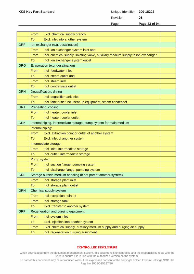
KKS Key Part Standard Unique Identifier: 200-18202
Revision: 05
Page: Page 43 of 94
CONTROLLED DISCLOSURE
When downloaded from the document management system, this document is uncontrolled and the responsibility rests with the user to ensure it is in line with the authorized version on the system.
No part of this document may be reproduced without the expressed consent of the copyright holder, Eskom Holdings SOC Ltd,
Reg. No 2002/015527/30.
From Excl. chemical supply branch
To Excl. inlet into another system
GRF Ion exchanger (e.g. desalination)
From Incl. ion exchanger system inlet and
From Incl. chemical supply isolating valve, auxiliary medium supply to ion exchanger
To Incl. ion exchanger system outlet
GRG Evaporation (e.g. desalination)
From Incl. feedwater inlet
To Incl. steam outlet and
From Incl. steam inlet
To Incl. condensate outlet
GRH Degasification, drying
From Incl. degasifier tank inlet
To Incl. tank outlet Incl. heat up equipment, steam condenser
GRJ Preheating, cooling
From Incl. heater, cooler inlet
To Incl. heater, cooler outlet
GRK Internal piping, intermediate storage, pump system for main medium
Internal piping:
From Excl. extraction point or outlet of another system
To Excl. inlet of another system
Intermediate storage:
From Incl. inlet, intermediate storage
To Incl. outlet, intermediate storage
Pump system:
From Incl. suction flange, pumping system
To Incl. discharge flange, pumping system
GRL Storage outside medium handling (if not part of another system)
From Incl. storage plant inlet
To Incl. storage plant outlet
GRN Chemical supply system
From Incl. extraction point or
From Incl. storage tank
To Excl. transfer to another system
GRP Regeneration and purging equipment
From Incl. system inlet
To Excl. injection into another system
From Excl. chemical supply, auxiliary medium supply and purging air supply
To Incl. regeneration purging equipment

KKS Key Part Standard Unique Identifier: 200-18202
Revision: 05
Page: Page 44 of 94
CONTROLLED DISCLOSURE
When downloaded from the document management system, this document is uncontrolled and the responsibility rests with the user to ensure it is in line with the authorized version on the system.
No part of this document may be reproduced without the expressed consent of the copyright holder, Eskom Holdings SOC Ltd,
Reg. No 2002/015527/30.
GRQ Injection device for main medium
From Incl. injection device or
From Excl. chemical supply junction
To Incl. inlet into another system
GRR Flushing water and residue removal incl. neutralization
From Excl. outlet of the respective system
To Excl. transfer point of another system
GRS Sludge thickener
From Excl. outlet of the respective system
To Excl. transfer point of another system
GRT Heating, cooling and flushing medium distribution
From Incl. heating, cooling and flushing medium production or
From Excl. heating, cooling and flushing medium supply junction
To Excl. consumer and
From Excl. consumer
GRX Control medium supply for closed/open loop control and protection equipment
GRY Closed/open loop control and protection equipment
GT WATER RECOVERY FROM DOMESTIC LIQUID WASTE (SEWAGE)
GTA Liquid waste water recovery collection and discharge piping system
From Excl. final filtration
To Excl. inlet to another system
GTB Dirty water system
Grit systems for Boiler Grit handling and floor washing drainage to be added as another system
GTC Clean water system
GTD Ash conveyor washing system
GTE Bottom ash cooling system
GTF Ash conditioning system
GTG Coal stockyard drainage
Excl. Drains and dam construction. Return system only
GTH Ash dump dam make-up water
GU COLLECTION AND DISCHARGE SYSTEM FOR RAIN WATER
GUA Common discharge piping and channel system - Boiler and Aux bay building
GUB Storage system -Turbine building
GUC Rainwater collection and drainage system - WTP/LPS building
GUD Rainwater collection and drainage system - Admin and other general building
GUE Rainwater collection and drainage system - Roads and contractors yards
GUF Rainwater collection and drainage system - Turbine building

KKS Key Part Standard Unique Identifier: 200-18202
Revision: 05
Page: Page 45 of 94
CONTROLLED DISCLOSURE
When downloaded from the document management system, this document is uncontrolled and the responsibility rests with the user to ensure it is in line with the authorized version on the system.
No part of this document may be reproduced without the expressed consent of the copyright holder, Eskom Holdings SOC Ltd,
Reg. No 2002/015527/30.
GV LUBRICANT SUPPLY SYSTEM 2
GVA Lubricant Supply System 2
GY CLOSED/OPEN CONTROL LOOP AND PROTECTION EQUIPMENT
GYA Control desk in control room
GYB Control panel in control room
GYC Local control panel, desk and solenoid operated valve panel
GYG Marshaling panel
GYH Measuring rack
GYJ VSD Field equipment panels 2
GYK DC supply incl. associated equipment
GYL AC supply and distribution
GYQ Computer equipment

KKS Key Part Standard Unique Identifier: 200-18202
Revision: 05
Page: Page 46 of 94
CONTROLLED DISCLOSURE
When downloaded from the document management system, this document is uncontrolled and the responsibility rests with the user to ensure it is in line with the authorized version on the system.
No part of this document may be reproduced without the expressed consent of the copyright holder, Eskom Holdings SOC Ltd,
Reg. No 2002/015527/30.
A.6 Conventional Heat Generation
H CONVENTIONAL HEAT GENERATION Rev
HA PRESSURE PARTS SYSTEM
HAA LP-partial preheating system (flue gas heated)
From Incl. LP-partial preheating system inlet
To Incl. LP-partial preheating system outlet
HAB HP-partial preheating system (flue gas heated)
From Incl. HP-partial preheating system inlet
To Incl. HP-partial preheating system outlet
HAC Economizer system
From Incl. boiler inlet header
To Excl. evaporator inlet incl. controllable
HAD Evaporator system
From Incl. evaporator system inlet
To Incl. evaporator system outlet
To Incl. steam separator vessel and water collecting vessel (once through) or
To Excl. water steam separator collecting vessel (drum)
HAG Circulating equipment (incl. circulating pumps)
From Excl. steam separator vessel
From Incl. water collecting vessel (once through)
From Excl. water steam separator collecting vessel (drum)
To Excl. heating surfaces system inlet (discharge systems are covered under ‘L’)
To Excl. feedwater system
HAH HP-super heater system
From Excl. evaporator system outlet
To Incl. boiler outlet header
HAJ Reheating system
From Incl. reheater inlet header
To Incl. reheater outlet header
HAK Secondary reheating system
From Incl. secondary reheater inlet header
To Incl. secondary reheater outlet header
HAM Triflux system
From Incl. Triflux system inlet
To Incl. Triflux system outlet
HAN Drainage, discharge and venting of pressure parts system
From Incl. collecting point or
From Excl. final drain/vent valve
From Excl. transfer point to another system
HAV Lubricant supply system
HAW Sealing medium supply system 1
HAX Control medium supply for closed/open loop control and protection equipment

KKS Key Part Standard Unique Identifier: 200-18202
Revision: 05
Page: Page 47 of 94
CONTROLLED DISCLOSURE
When downloaded from the document management system, this document is uncontrolled and the responsibility rests with the user to ensure it is in line with the authorized version on the system.
No part of this document may be reproduced without the expressed consent of the copyright holder, Eskom Holdings SOC Ltd,
Reg. No 2002/015527/30.
H CONVENTIONAL HEAT GENERATION Rev
HAY Closed/open loop control and protection equipment
HB SUPPORTING STRUCTURE, SKIN CASING, STEAM GENERATOR COMBUSTION CHAMBER
HBA Structure incl. foundation
HBB Casing, insulation
HBC Brick lining incl. insulation brickwork
HBD Platforms, stairs, catwalks and galleries
HBK Steam generator-combustion chamber, furnace, gas pass
From Excl. combustion area
To Excl. flue gas ducting system inlet
HC CLEANING EQUIPMENT FOR THE HEATING SURFACES ON THE FLUE GAS SIDE
HCA Air sootblower system 1
From Excl. supply system connection
HCB Steam sootblower system 1
From Excl. supply system connection
HCC Water sootblower system 1
From Excl. supply system connection
HCD Flushing system
From Excl. supply system connection
HCE Vibrating equipment
HCF Shotblast cleaning system
HCG Soundwave system
HCV Lubricant supply system
HCW Sealing medium supply
HCX Control medium supply for closed/open loop control and protection equipment
HCY Closed/open loop control and protection equipment
HD ASH AND SLAG HANDLING
HDA Furnace ash and slag removal
From Incl. ash hopper and removal appliance
To Excl. transfer point of removal system
HDC Ash return system incl. temporary storage 2
From Incl. removal equipment for heat recovery surfaces or 2
From Excl. *HDD*, *HDE*, *HDF* 2
To Excl. ash disposal system *ETG* or 2
To Excl. inlet of another system 2
HDD Mechanical dust handling and return system
From Excl. flue gas duct inlet
To Excl. flue gas duct outlet
To Excl. discharge to other system
HDE Electrostatic precipitator and return system
From Excl. flue gas duct inlet

KKS Key Part Standard Unique Identifier: 200-18202
Revision: 05
Page: Page 48 of 94
CONTROLLED DISCLOSURE
When downloaded from the document management system, this document is uncontrolled and the responsibility rests with the user to ensure it is in line with the authorized version on the system.
No part of this document may be reproduced without the expressed consent of the copyright holder, Eskom Holdings SOC Ltd,
Reg. No 2002/015527/30.
H CONVENTIONAL HEAT GENERATION Rev
To Excl. flue gas duct outlet
To Excl. discharge to other system
HDF Cyclone dust removal and return system
From Excl. flue gas duct inlet
To Excl. flue gas duct outlet
To Excl. discharge to other system
HDU Carrier air supply system 1
From Excl. branch off or 1
From Incl. compressor system 1
To Excl. inlet to carrier air system 1
HDW Sealing medium supply
HDY Closed/open loop control and protection equipment
HF BUNKER, FEEDER AND PULVERIZING SYSTEM (MILLS)
HFA Bunker for pulverizing system (mill bunker)
From Excl. inlet point
To Incl. bunker outlet gate
HFB Feeder system
From Excl. bunker outlet gate
To Excl. pulverizing system inlet
HFC Pulverizing system (incl. classifier and mill system)
From Incl. pulverizing system inlet
To Excl. classifier outlet pipes
HFD Flue gas return suction
From Excl. outlet of another system
To Excl. pulverizer plant
HFE Mill air system, transport system
From Incl. air inlet or
From Excl. branch off (‘HLA’)
To Excl. feeder outlet pipe or
To Excl. pulverizing system or
To Excl. flue gas recirculation
HFF Vapours flue gas system
From Excl. separation system
To Excl. another system
HFG Dust bin and feeder system after central pulverizing system (indirect lighting-up)
From Excl. pulverizing outlet system
To Incl. pulverized coal storage bunker outlet incl.
HFV Lubricant supply system
HFW Sealing medium supply (seal air fans)
HFX Control medium supply for closed open/loop control and protection equipment
HFY Closed/open loop control and protection equipment

KKS Key Part Standard Unique Identifier: 200-18202
Revision: 05
Page: Page 49 of 94
CONTROLLED DISCLOSURE
When downloaded from the document management system, this document is uncontrolled and the responsibility rests with the user to ensure it is in line with the authorized version on the system.
No part of this document may be reproduced without the expressed consent of the copyright holder, Eskom Holdings SOC Ltd,
Reg. No 2002/015527/30.
H CONVENTIONAL HEAT GENERATION Rev
HH MAIN FIRING SYSTEM (ELECTRIC POWERED)
HHA Main burner
From Incl. fuel and air side burner equipment inlet
HHB Retarded combustion grate (chain grate)
From Incl. retarded combustion grate inlet
To Incl. inlet of another system
HHC Combustion grate
From Incl. fuel receiving point or
From Incl. firing grate inlet
To Excl. inlet of another system
HHD Other burner equipment (e.g. vapour burner, grit burner)
From Incl. inlet
To Incl. outlet
HHE Pulverized coal storage facility, conveying and distribution
From Excl. pulverizing system outlet or
From Excl. pulverized coal storage facility outlet at the central pulverizing system ‘HFG’ or
To Excl. outlet of another system
To Excl. main burner system
HHF Intermediate oil storage facility, pumping and distribution
From Excl. connection to main supply line or
From Incl. intermediate tank
To Excl. main burner equipment
HHG Gas reduction, distribution
From Excl. connection to main supply line
To Excl. main burner equipment distribution
HHH Intermediate storage facility, conveying and distribution of other fuels, Medium 1
HHJ Intermediate storage facility, conveying and distribution of other fuels, Medium 2
HHK Intermediate storage facility, conveying and distribution of other fuels, Medium 3
HHL Combustion air supply system to burner (secondary air)
From Excl. combustion burner
To Excl. burner
HHM Atomizing medium supply (steam)
From Excl. supply system connection
To Excl. burner
HHN Atomizing medium supply (air)
From Excl. supply system connection
To Excl. burner
HHP Cooling medium supply (steam)
From Excl. supply system connection
To Excl. burner

KKS Key Part Standard Unique Identifier: 200-18202
Revision: 05
Page: Page 50 of 94
CONTROLLED DISCLOSURE
When downloaded from the document management system, this document is uncontrolled and the responsibility rests with the user to ensure it is in line with the authorized version on the system.
No part of this document may be reproduced without the expressed consent of the copyright holder, Eskom Holdings SOC Ltd,
Reg. No 2002/015527/30.
H CONVENTIONAL HEAT GENERATION Rev
HHQ Cooling medium supply (air)
From Incl. supply system connection
To Excl. burner
HHR Purging medium supply (steam)
From Excl. supply system connection
To Excl. burner
HHS Purging medium supply (air)
From Excl. supply system connection
To Excl. burner
HHT Heating medium supply (steam)
From Excl. supply system connection
To Excl. burner and
From Excl. burner
To Excl. supply of another system
HHU Heating medium supply (warm water)
From Excl. supply system connection
To Excl. burner and
From Excl. burner
To Excl. supply of another system
HHV Lubricant supply system 1
HHW Sealing medium supply
HHX Control medium supply for closed/open loop control and protection equipment
HHY Closed/open loop control and protection equipment
HHZ Electric heating system 1
HJ LIGHTING-UP SYSTEM (WHEN INDEPENDENT OF MAIN FIRING SYSTEM)
HJA Lighting-up burner
From Incl. fuel and air side of burner equipment inlet
To Excl. pipework
HJE Pulverized coal storage facility, conveying and distribution
From Excl. pulverizing system outlet or
From Excl. pulverizing coal storage facility outlet at the central pulverizing system HFG or
From Excl. outlet of another system
To Excl. ignition burner system
HJF Intermediate oil storage facility pumping and distribution
From Excl. connection to main supply line or
From Incl. intermediate tank
To Excl. lighting-up burner system
HJG Gas reticulation distribution
From Excl. connection to main supply line (bus main)
To Excl. lighting-up burner equipment
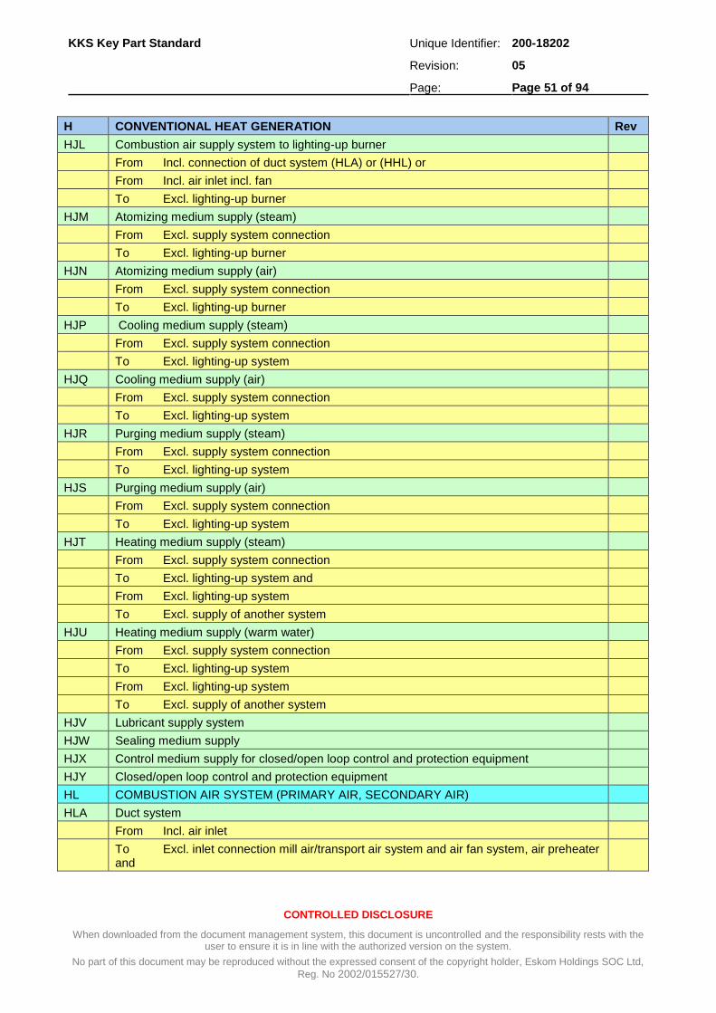
KKS Key Part Standard Unique Identifier: 200-18202
Revision: 05
Page: Page 51 of 94
CONTROLLED DISCLOSURE
When downloaded from the document management system, this document is uncontrolled and the responsibility rests with the user to ensure it is in line with the authorized version on the system.
No part of this document may be reproduced without the expressed consent of the copyright holder, Eskom Holdings SOC Ltd,
Reg. No 2002/015527/30.
H CONVENTIONAL HEAT GENERATION Rev
HJL Combustion air supply system to lighting-up burner
From Incl. connection of duct system (HLA) or (HHL) or
From Incl. air inlet incl. fan
To Excl. lighting-up burner
HJM Atomizing medium supply (steam)
From Excl. supply system connection
To Excl. lighting-up burner
HJN Atomizing medium supply (air)
From Excl. supply system connection
To Excl. lighting-up burner
HJP Cooling medium supply (steam)
From Excl. supply system connection
To Excl. lighting-up system
HJQ Cooling medium supply (air)
From Excl. supply system connection
To Excl. lighting-up system
HJR Purging medium supply (steam)
From Excl. supply system connection
To Excl. lighting-up system
HJS Purging medium supply (air)
From Excl. supply system connection
To Excl. lighting-up system
HJT Heating medium supply (steam)
From Excl. supply system connection
To Excl. lighting-up system and
From Excl. lighting-up system
To Excl. supply of another system
HJU Heating medium supply (warm water)
From Excl. supply system connection
To Excl. lighting-up system
From Excl. lighting-up system
To Excl. supply of another system
HJV Lubricant supply system
HJW Sealing medium supply
HJX Control medium supply for closed/open loop control and protection equipment
HJY Closed/open loop control and protection equipment
HL COMBUSTION AIR SYSTEM (PRIMARY AIR, SECONDARY AIR)
HLA Duct system
From Incl. air inlet
To Excl. inlet connection mill air/transport air system and air fan system, air preheater and

KKS Key Part Standard Unique Identifier: 200-18202
Revision: 05
Page: Page 52 of 94
CONTROLLED DISCLOSURE
When downloaded from the document management system, this document is uncontrolled and the responsibility rests with the user to ensure it is in line with the authorized version on the system.
No part of this document may be reproduced without the expressed consent of the copyright holder, Eskom Holdings SOC Ltd,
Reg. No 2002/015527/30.
H CONVENTIONAL HEAT GENERATION Rev
To Excl. gas-turbine and exhaust gas system
HLB Air fan system (primary air, forced draught, secondary air fans)
From Incl. inlet air suction
To Excl. outlet air fan discharge
HLC Auxiliary air preheater (not by means of flue gas) (steam)
From Incl. air preheater inlet
To Incl. air preheater outlet
HLD Air heater (by means of flue gas)
From Incl. air heater inlet
To Incl. air heater outlet
HLV Lubricant supply system
HLW Sealing medium supply
HLX Control medium supply for closed/open loop control and protection equipment
HLY Closed/open loop control and protection equipment
HN FLUE GAS EXHAUST (INDUCED DRAUGHT )
HNA Duct system
From Excl. boiler outlet or
From Excl. outlet of another system
To Excl. smoke stack but excluding air heater, flue gas dust extraction, induced draught fan, gas scrubbing, chemical flue gas processing
HNC Induced draught fan system (ID fan )
From Incl. induced draught fan inlet
To Incl. induced draught fan outlet
HNE Smoke stack
From Incl. inlet
HNF Flue gas circulation
From Excl. flue gas main exhaust connection
To Excl. inlet of another system incl. fan system
HNU Flue gas pressure relief system 2
Task to relief pressure in flue gas system
HNV Lubricant supply system 2
HNW Sealing fluid supply system 2
HNX Fluid supply system for control and protection equipment 2
HNY Closed/open loop control and protection equipment
HT CHEMICAL FLUE GAS TREATMENT INCL. RESIDUE REMOVAL ABSORPTIVE PROCESS
HTA Flue gas ducting system within HT
From Excl. HNA
To Excl. inlet to HNA
HTB Flue gas-side heat exchanger, gas heater (not HU)
HTC Flue gas fan system
From Incl. inlet

KKS Key Part Standard Unique Identifier: 200-18202
Revision: 05
Page: Page 53 of 94
CONTROLLED DISCLOSURE
When downloaded from the document management system, this document is uncontrolled and the responsibility rests with the user to ensure it is in line with the authorized version on the system.
No part of this document may be reproduced without the expressed consent of the copyright holder, Eskom Holdings SOC Ltd,
Reg. No 2002/015527/30.
H CONVENTIONAL HEAT GENERATION Rev
To Incl. outlet
HTD Flue gas scrubbing system
From Incl. flue gas inlet
To Incl. moisture separator outlet
HTE Flue gas cleaning and filtering system
Task: additional cleaning within HT; not belonging to HP, HQ and HR
HTF Absorption cycle
From Incl. inlet
To Incl. outlet
HTG Oxidation system incl. supply system
To Excl. user or scrubber
HTJ Absorbent supply system incl. storage system
To Excl. mashing (HTK)
HTK Absorbent preparation and distribution system
From Incl. mashing, slaking
To Excl. user or scrubber
HTL Piping system for discharge of solids 2
HTM Thickening and solids dewatering system 2
HTN Solids drying, compacting system 2
HTP (Solids/product) forwarding, storage, loading system 2
HTQ Water supply and disposal system 2
HTS Chemicals and additives supply system 2
HTT Drainage systems 2
Task: water collecting, storage, return 2
HTV Lubricant supply system 2
HTX Fluid supply system for control and protection equipment 2
HTW Sealing fluid supply system 1
HTY Control and protection equipment 2
HY CLOSED/OPEN LOOP CONTROL AND PROTECTION EQUIPMENT
HYA Control desk in control room
HYB Control panel in control room
HYC Local control panel, desk and solenoid operated valve panel
HYD PLC
HYE Spare
HYF Equipment room cubicle
HYG Marshaling panel
HYH Measurement rack
HYJ VSD Field equipment panels 2
HYK DC supply incl. associated equipment
HYL AC supply and distribution
HYQ Computer equipment

KKS Key Part Standard Unique Identifier: 200-18202
Revision: 05
Page: Page 54 of 94
CONTROLLED DISCLOSURE
When downloaded from the document management system, this document is uncontrolled and the responsibility rests with the user to ensure it is in line with the authorized version on the system.
No part of this document may be reproduced without the expressed consent of the copyright holder, Eskom Holdings SOC Ltd,
Reg. No 2002/015527/30.
A.7 L – Steam, water, Gas Cycle
L STEAM, WATER, GAS CYCLE Rev
LA FEED WATER SYSTEM
LAA Feed water tank, deaerating
From Incl. deaerating installation or feed water tank inlet
To Incl. tank outlet incl. heating installation and vapour condenser
LAB Feed water piping system (incl. interconnecting piping in feed water pumping system and feed water heating)
From Excl. feed water tank outlet
To Excl. boiler inlet header
LAC Feed water pumping system (excl. interconnecting piping) between booster and main pump)
From Incl. pumping system suction nozzle
To Incl. pumping system discharge nozzle
LAD Feed water heating system (HP heaters)
From Incl. heater inlet
To Incl. heater outlet incl. desuperheater and drain cooler when integral part of heater
LAE HP bypass water injection system
Superheater attemporator spray system, HP bypass spray system)
From Excl. feed water piping system
To Excl. user (e.g. superheater attemporator)
LAF Intermediate pressure water injection system (reheater attemporator spray system)
From Excl. Feedwater pump extraction (take-off connection) or
From Excl. branch of another system
To Excl. user (e.g. reheater attemporator)
LAH Start-up and shut-down piping system (e.g. filling system)
From Excl. outlet of another system
To Excl. feed water system intake (e.g. feed water tank)
LAJ Start-up and shut-down pumping system (e.g. filling system)
From Incl. pump suction flange
To Incl. pump discharge flange
LAR Emergency feed water piping system incl. Storage (excl. emergency feed water pumping system)
From Excl. junction from another system
To Excl. feed water piping system intake
LAS Emergency feed water pumping system
From Incl. pump suction flange
To Incl. pump discharge flange
LAW Feedwater sealing water system
LAX Control medium supply for closed/open loop control and protection equipment
LAY Closed/open loop control and protection equipment
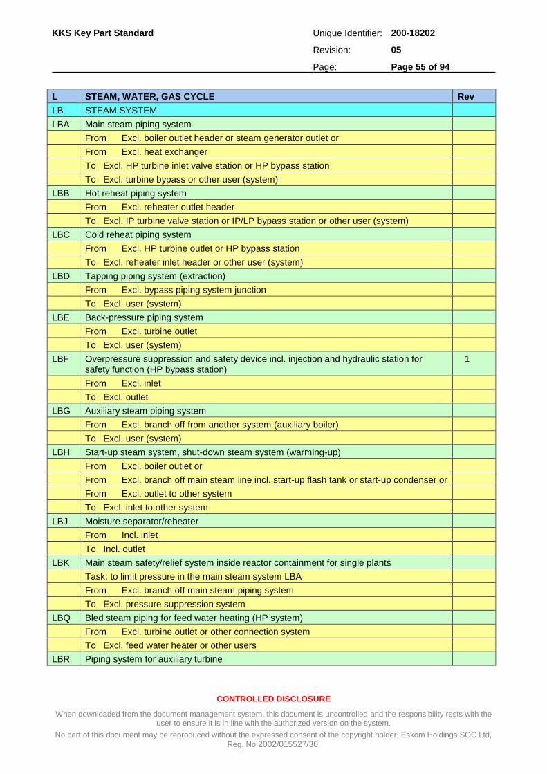
KKS Key Part Standard Unique Identifier: 200-18202
Revision: 05
Page: Page 55 of 94
CONTROLLED DISCLOSURE
When downloaded from the document management system, this document is uncontrolled and the responsibility rests with the user to ensure it is in line with the authorized version on the system.
No part of this document may be reproduced without the expressed consent of the copyright holder, Eskom Holdings SOC Ltd,
Reg. No 2002/015527/30.
L STEAM, WATER, GAS CYCLE Rev
LB STEAM SYSTEM
LBA Main steam piping system
From Excl. boiler outlet header or steam generator outlet or
From Excl. heat exchanger
To Excl. HP turbine inlet valve station or HP bypass station
To Excl. turbine bypass or other user (system)
LBB Hot reheat piping system
From Excl. reheater outlet header
To Excl. IP turbine valve station or IP/LP bypass station or other user (system)
LBC Cold reheat piping system
From Excl. HP turbine outlet or HP bypass station
To Excl. reheater inlet header or other user (system)
LBD Tapping piping system (extraction)
From Excl. bypass piping system junction
To Excl. user (system)
LBE Back-pressure piping system
From Excl. turbine outlet
To Excl. user (system)
LBF Overpressure suppression and safety device incl. injection and hydraulic station for safety function (HP bypass station)
1
From Excl. inlet
To Excl. outlet
LBG Auxiliary steam piping system
From Excl. branch off from another system (auxiliary boiler)
To Excl. user (system)
LBH Start-up steam system, shut-down steam system (warming-up)
From Excl. boiler outlet or
From Excl. branch off main steam line incl. start-up flash tank or start-up condenser or
From Excl. outlet to other system
To Excl. inlet to other system
LBJ Moisture separator/reheater
From Incl. inlet
To Incl. outlet
LBK Main steam safety/relief system inside reactor containment for single plants
Task: to limit pressure in the main steam system LBA
From Excl. branch off main steam piping system
To Excl. pressure suppression system
LBQ Bled steam piping for feed water heating (HP system)
From Excl. turbine outlet or other connection system
To Excl. feed water heater or other users
LBR Piping system for auxiliary turbine

KKS Key Part Standard Unique Identifier: 200-18202
Revision: 05
Page: Page 56 of 94
CONTROLLED DISCLOSURE
When downloaded from the document management system, this document is uncontrolled and the responsibility rests with the user to ensure it is in line with the authorized version on the system.
No part of this document may be reproduced without the expressed consent of the copyright holder, Eskom Holdings SOC Ltd,
Reg. No 2002/015527/30.
L STEAM, WATER, GAS CYCLE Rev
From Excl. branch off main turbine or
From Excl. branch off another system or
From Excl. branch or auxiliary turbine outlet
To Excl. branch off or auxiliary turbine isolating valve or
To Excl. inlet to another system
LBS Bled steam system for main condensate heating (LP-system)
From Excl. turbine outlet or other connection system
To Excl. main condensate heater or (LP-heater) feed water tank/deaerator or other user
LBT Emergency condensation
From Excl. steam generation outlet
From Excl. main steam piping system branch incl. Condenser
To Excl. inlet into another system
LBU Common steam dump piping
LBW Sealing steam system
LBX Control medium supply for closed/open loop control and protection equipment
LBY Closed/open loop control and protection equipment
LC CONDENSATE SYSTEM
LCA Main condensate piping system (excl. main condensate pumping system, main condensate heating, LP heater, condensate polishing)
From Excl. condensate tank outlet (hotwell) and other system
To Excl. deaerator inlet
LCB Main condensate pumping system (extraction pump)
From Incl. pumping system suction nozzle
To Incl. pumping system discharge nozzle
LCC Main condensate heater system (LP heaters)
From Incl. heater inlet
To Incl. heater outlet incl. desuperheater and cooler when integral part of heater
LCE Low pressure water injection system (for IP/LP bypass system)
From Excl. condensate piping system or
From Excl. condensate auxiliary condensate piping system
To Excl. user (e.g. IP/LP bypass station)
LCF Auxiliary turbine condensate piping system
From Excl. condenser outlet
To Excl. feed into another system excl. branch
turbine condensate pumping system
LCG Auxiliary turbine condensate pumping system
From Incl. pump suction nozzle
To Incl. pump discharge nozzle
LCH High pressure heater distillate (condensate) system
(HP heater drain system, incl. drain cooler)
From Excl. HP heater outlet

KKS Key Part Standard Unique Identifier: 200-18202
Revision: 05
Page: Page 57 of 94
CONTROLLED DISCLOSURE
When downloaded from the document management system, this document is uncontrolled and the responsibility rests with the user to ensure it is in line with the authorized version on the system.
No part of this document may be reproduced without the expressed consent of the copyright holder, Eskom Holdings SOC Ltd,
Reg. No 2002/015527/30.
L STEAM, WATER, GAS CYCLE Rev
To Excl. inlet to another system
LCJ Main condensate heater distillate (condensate) system
(LP heater drain system, incl. drain cooler and flash box)
From Excl. LP heater outlet
LCL Condensate drain system from steam generator, blow-down system
From Excl. pressure system branch or
From Excl. start-up releaser or
From Excl. blow-down vessel
To Excl. feed into another system
LCM Drainage, dewatering condensate system (clean drain collecting and return system)
From Incl. low pressure flash/collection tank or
From Excl. last drainage component or
From Excl. another collection system
To Excl. feed into another system
LCN Auxiliary steam condensate system (collecting and return system)
From Excl. (steam) - user
To Excl. feed into another system
LCP Reserve condensate system incl. storage, piping and pumping
From Excl. branch off another system
To Excl. feed into another system
LCQ Steam generator blow-down system (incl. unit start-up drains)
From Excl. steam generator outlet
From Incl. blow-down flashtank (caustic flashtank)
To Excl. feed into another system
LCR Reserve condensate distribution system
From Excl. branch off another system
To Excl. feed into another system
LCS Reheater-condensate system (moisture separator/reheater)
From Excl. reheater
To Excl. feed into another system
LCT Moisture separator drains system (moisture separator/reheater)
From Excl. water separator
To Excl. feed into another system
LCW Sealing and cooling condensate system
From Excl. branch off another system
To Excl. user, incl. return line
LCX Control medium supply for closed/open loop control and protection equipment
LCY Closed/open loop control and protection equipment
LD CONDENSATE POLISHING PLANT
LDA Fluid treatment extraction (if not part another system)
From Excl. fluid treatment system outlet

KKS Key Part Standard Unique Identifier: 200-18202
Revision: 05
Page: Page 58 of 94
CONTROLLED DISCLOSURE
When downloaded from the document management system, this document is uncontrolled and the responsibility rests with the user to ensure it is in line with the authorized version on the system.
No part of this document may be reproduced without the expressed consent of the copyright holder, Eskom Holdings SOC Ltd,
Reg. No 2002/015527/30.
L STEAM, WATER, GAS CYCLE Rev
To Excl. inlet into another system
LDB Filtering, mechanical purification
From Incl. separator equipment inlet
To Incl. separator equipment outlet
LDC Ventilation, gas injection
From Excl. atmosphere or
From Incl. gas supply
To Excl. inlet to another system
LDD Precipitation (e.g. decarbonization) (flocculation)
From Incl. precipitation inlet
To Incl. precipitation outlet
LDE Acid dosing (e.g. decarbonization)
From Incl. acid dosing equipment or
From Excl. chemical supply branch
To Excl. any other system inlet
LDF Ion exchanger (e.g. desalination)
From Incl. ion exchanger inlet
To Incl. ion exchanger outlet
LDG Evaporation (e.g. desalination)
From Incl. feedwater inlet
To Incl. steam outlet and
From Incl. hot steam inlet
To Incl. condensate outlet
LDH Degasification, drying
From Incl. degasifier, tank inlet
To Incl. tank outlet incl. heating equipment for steam condenser
LDJ Heating, cooling
From Incl. heater, cooler inlet
To Incl. heater, cooler outlet
LDK Internal piping, intermediate storage, pump system for main medium Internal piping:
From Excl. outlet of another system
To Excl. inlet into another system
To Incl. outlet medium treatment
Intermediate storage:
From Incl. inlet intermediate storage
To Incl. outlet intermediate storage
Pump system:
From Incl. suction flange of pumping system
To Incl. discharge flange of pumping system

KKS Key Part Standard Unique Identifier: 200-18202
Revision: 05
Page: Page 59 of 94
CONTROLLED DISCLOSURE
When downloaded from the document management system, this document is uncontrolled and the responsibility rests with the user to ensure it is in line with the authorized version on the system.
No part of this document may be reproduced without the expressed consent of the copyright holder, Eskom Holdings SOC Ltd,
Reg. No 2002/015527/30.
L STEAM, WATER, GAS CYCLE Rev
LDL Storage not included in medium treatment (if not part of another system)
From Incl. storage plant inlet
To Incl. storage plant outlet
LDN Chemical supply system
From Incl. extraction point or
From Incl. storage tank
To Excl. transfer to another system
LDP Regeneration and purging equipment
From Incl. system inlet
To Excl. injection into another system
From Excl. chemical supply, auxiliary medium supply and purging air supply
To Incl. regeneration purging equipment
LDQ Injection device for main medium
From Incl. injection device or
From Excl. chemical supply junction
To Incl. inlet into another system
LDR Flushing water and residue removal incl. neutralization
From Excl. system concerned outlet
To Excl. transfer point of another system
LDS Sludge thickener
From Excl. system concerned outlet
To Excl. transfer point of another system
LDT Heating, cooling and flushing medium distribution
From Incl. heating, cooling and flushing medium production or
From Excl. heating, cooling and flushing medium supply junction
To Excl. consumer and
From Excl. consumer
LDX Control medium supply for closed/open loop control and protection equipment
LDY Closed/open loop control and protection equipment
LF COMMON INSTALLATION FOR STEAM, WATER, GAS CYCLE
LFC Common drain and vent system
LFG Secondary side steam generator tube lancing system
From Excl. primary coolant heat exchanger outlet
To Excl. primary coolant heat exchanger inlet
LFJ Steam generator and standby conservation
LFN Dosing system for feedwater and condensate cycle, incl. dosing in the vessel and turbine area
LY CLOSED/OPEN LOOP CONTROL AND PROTECTION EQUIPMENT (MAINLY
USED FOR CONDENSATE POLISHING PLANT IN ESKOM)
LYA Control desk in control room
LYB Control panel in control room

KKS Key Part Standard Unique Identifier: 200-18202
Revision: 05
Page: Page 60 of 94
CONTROLLED DISCLOSURE
When downloaded from the document management system, this document is uncontrolled and the responsibility rests with the user to ensure it is in line with the authorized version on the system.
No part of this document may be reproduced without the expressed consent of the copyright holder, Eskom Holdings SOC Ltd,
Reg. No 2002/015527/30.
L STEAM, WATER, GAS CYCLE Rev
LYC Local control panel, desk and solenoid operated valve panel
LYD PLC
LYE Spare
LYF Equipment room cubicle
LYG Marshalling panel
LYH Measurement rack
LYJ VSD Field equipment panels 2
LYK DC supply incl. associated equipment
LYL AC supply and distribution
LYQ Computer equipment

KKS Key Part Standard Unique Identifier: 200-18202
Revision: 05
Page: Page 61 of 94
CONTROLLED DISCLOSURE
When downloaded from the document management system, this document is uncontrolled and the responsibility rests with the user to ensure it is in line with the authorized version on the system.
No part of this document may be reproduced without the expressed consent of the copyright holder, Eskom Holdings SOC Ltd,
Reg. No 2002/015527/30.
A.8 M – Main Machine Set
MA STEAM TURBINE PLANT Rev
MAA High pressure turbine
From Incl. inlet device (emergency stop valve or combined emergency stop valve or control valve)
To Incl. extraction, tapping and steam exhaust nozzle and
To Incl. the interface of another system within the turbine
MAB Intermediate pressure turbine
From Incl. crossover pipe incl. control elements or
From Incl. intercept valve
To Incl. extraction, tapping and steam exhaust nozzle and
To Incl. the interface of another system within the turbine
MAC Low pressure turbine
From Incl. crossover pipe incl. control elements or
From Incl. intercept valve or steam inlet nozzle (in reheat installation without intercept valves)
To Incl. extraction, tapping and steam exhaust nozzle and
To Incl. the interface of another system within the turbine
MAD Bearing assembly
MAG Condensing system
From Incl. condenser neck or inlet nozzle
To Incl. condenser outlet nozzle incl. instrumentation equipment associated with the condenser
(incl. hotwell or directly connected tanks/vessels or total air cooled condensing system)
MAH Air ejector motive water system (if fitted separately from MAJ)
From Incl. outlet of another system
To Incl. ejector inlet
MAJ Air evacuation system
From Excl. condenser outlet or outlet of another system
To Excl. atmosphere or another system
MAK Transmission gear between prime mover and driven machine
MAL Turbine drain and vent system
From Incl. collection point or outlet of another system
From Incl. last drain valve
To Excl. inlet to drain collection vessel or inlet to another system
MAM Leak-off steam system
From Excl. branch or leak-off point
To Excl. inlet into another system
MAN IP/LP bypass station (incl. attemporation spray system)
From Incl. IP/LP bypass isolating valve and
From Incl. attemporation spray valve

KKS Key Part Standard Unique Identifier: 200-18202
Revision: 05
Page: Page 62 of 94
CONTROLLED DISCLOSURE
When downloaded from the document management system, this document is uncontrolled and the responsibility rests with the user to ensure it is in line with the authorized version on the system.
No part of this document may be reproduced without the expressed consent of the copyright holder, Eskom Holdings SOC Ltd,
Reg. No 2002/015527/30.
MA STEAM TURBINE PLANT Rev
To Excl. steam inlet in condenser or another system
MAP LP bypass station
From Excl. bypass unit and branch off steam system
To Excl. condenser
MAQ Vent system (if fitted separately from (MAL)
From Incl. deaerator unit
To Excl. inlet into another system or atmosphere
MAV Lubrication oil supply system
From Incl. dedicated lubrication oil tank or common oil tank or
From Excl. lubricant supply branch
To Excl. user and return
From Excl. user
MAW Gland steam heating and cooling system
From Excl. branch or leak-off pint at casing nozzle
To Excl. steam gland user
To Excl. condenser and gland leak-off system or
To Incl. gland sealing steam condenser or
To Excl. heating and cooling steam user in each case
MAX Non-electric control and protection equipment incl. medium supply system
MAY Closed/open loop control and protection equipment
MK GENERATOR
MKA Generator casing incl. stator and rotor incl. all internal cooling equipment
To Incl. generator bushing and balancing tank
MKB Excitation (use only if ‘MKC‘ is insufficient)
MKC Excitation
MKD Bearing assembly
MKF Liquid cooling (except oil cooling) incl. intermediate cooler
From Excl. stator/rotor outlet
To Excl. stator/rotor inlet
MKG Stator/rotor gas cooling (except N2 cooling) incl. H2 and CO2 supply
From Excl. stator/rotor outlet
To Excl. stator/rotor inlet
MKH Stator/rotor N2 cooling incl. N2 supply
From Excl. stator/rotor outlet
To Excl. stator/rotor inlet incl. N2 supply
MKJ Stator/rotor Air cooling system
From Excl. stator/rotor outlet
To Excl. stator/rotor inlet
MKQ Exhaust gas system (if fitted separately from MKG and MKH)
MKU Oil cooling system incl. intermediate cooling circuits
From Excl. stator plate core outlet

KKS Key Part Standard Unique Identifier: 200-18202
Revision: 05
Page: Page 63 of 94
CONTROLLED DISCLOSURE
When downloaded from the document management system, this document is uncontrolled and the responsibility rests with the user to ensure it is in line with the authorized version on the system.
No part of this document may be reproduced without the expressed consent of the copyright holder, Eskom Holdings SOC Ltd,
Reg. No 2002/015527/30.
MA STEAM TURBINE PLANT Rev
To Excl. stator plate core inlet
MKV Lubricating supply system (if fitted separately for the generator)
MKW Seal oil system incl. supply and treatment plant
From Excl. seal oil system branch
To Excl. stator inlet and
From Excl. stator outlet
To Excl. inlet into another system, or in closed system
From Excl. stator outlet (incl. supply and treatment plant)
To Excl. stator inlet
MKY Closed/open loop control and protection equipment
MP COMMON EQUIPMENT FOR MAIN MACHINE SET
MPA Foundation
MPB Cowling
MPG Rack, support
MPR Forced air cooling system
MPS Drying and preservation system
MV LUBRICATION MEDIUM SUPPLY
MVA Lubrication oil supply system
From Incl. common lubrication oil tank or
From Excl. lubricant supply branch
To Excl. user and return
From Excl. user
MW SEALING FLUID SUPPLY SYSTEM
MWA Sealing fluid supply system
MX CONTROL MEDIUM SUPPLY
MXA Hydraulic storage
MXB Hydraulic oil supply
MY CLOSED/OPEN LOOP CONTROL AND PROTECTION EQUIPMENT
MYA Control desk in control room
MYB Control panel in control room
MYC Local control panel, desk and solenoid operated valve panel
MYD PLC
MYE Spare
MYF Equipment room cubicle
MYG Marshalling panel
MYH Measurement rack
MYJ VSD Field equipment panels 2
MYK DC supply incl. associated equipment
MYL AC supply and distribution
MYQ Computer equipment

KKS Key Part Standard Unique Identifier: 200-18202
Revision: 05
Page: Page 64 of 94
CONTROLLED DISCLOSURE
When downloaded from the document management system, this document is uncontrolled and the responsibility rests with the user to ensure it is in line with the authorized version on the system.
No part of this document may be reproduced without the expressed consent of the copyright holder, Eskom Holdings SOC Ltd,
Reg. No 2002/015527/30.
A.9 P – Cooling Water System
P COOLING WATER SYSTEM Rev
PA MAIN COOLING WATER SYSTEM
PAA Extraction, mechanical purification
From Incl. inlet system
To Incl. outlet of mechanical purification
PAB Piping, canal system for main cooling water
From Excl. fresh water production outlet (always without consumers)
To Incl. fresh water cooling outlet
From Excl. cooling tower outlet
To Excl. cooling tower inlet for closed circuit cooling
PAC Main cooling water pumping system
From Incl. suction flange of pumping system
To Incl. discharge flange of pumping system
PAD Cooling tower
From Incl. standpipe
To Incl. cooling basin outlet
PAE Cooling tower pump system (if separate)
PAH Condenser cleaning system Incl. all affiliated equipment
PAR Cooling tower make-up water piping system
From Excl. inlet
To Excl. inlet to another system
PAS Cooling tower make-up water pumping system
From Incl. pump system suction nozzle
To Incl. pump system discharge nozzle
PAV Lubrication supply system
PAX Control medium supply for closed/open loop control and protection equipment
PAY Closed/open loop control and protection equipment
PB MAIN COOLING WATER TREATMENT
PBA Supply line, distribution outside medium handling (if not part of another system)
From Excl. extraction point or
From Excl. outlet of another system
To Excl. medium treatment
From Excl. medium treatment outlet
To Excl. inlet into another system
PBB Filtering, mechanical purification
From Incl. separator equipment inlet
To Incl. separator equipment outlet
PBC Ventilation, gas injection
From Excl. atmosphere
From Incl. gas supply
To Excl. inlet into another system

KKS Key Part Standard Unique Identifier: 200-18202
Revision: 05
Page: Page 65 of 94
CONTROLLED DISCLOSURE
When downloaded from the document management system, this document is uncontrolled and the responsibility rests with the user to ensure it is in line with the authorized version on the system.
No part of this document may be reproduced without the expressed consent of the copyright holder, Eskom Holdings SOC Ltd,
Reg. No 2002/015527/30.
P COOLING WATER SYSTEM Rev
PBD Precipitation (e.g. decarbonization)
From Incl. precipitation inlet
To Incl. precipitation outlet
PBE Acid dosing (e.g. decarbonization)
From Incl. acid dosing equipment or
From Excl. chemical supply branch
To Excl. inlet into another system
PBF Ion exchanger (e.g. desalination)
From Incl. ion exchanger inlet and
From Incl. chemical supply isolating valve, auxiliary medium supply to ion exchanger
To Incl. ion exchanger outlet
PBG Evaporation (e.g. desalination)
From Incl. feedwater inlet
To Incl. steam outlet and
From Incl. hot steam inlet
To Incl. condensate outlet
PBH Degasification, drying
From Incl. degasifier tank inlet
To Incl. tank outlet including heating equipment steam condenser
PBJ Heating, cooling
From Incl. heater, cooler inlet
To Incl. heater, cooler outlet
PBK Internal piping, intermediate storage, pump system for main medium
Internal piping:
From Excl. outlet of another system
To Excl. inlet into another system
To Incl. medium treatment outlet
Intermediate storage:
From Incl. inlet, intermediate storage
To Incl. outlet, intermediate storage
Pump system:
From Incl. suction flange of pumping system
To Incl. discharge flange of pumping system
PBL Storage not included in medium treatment (and not part of another system)
From Incl. storage plant inlet
To Incl. storage plant outlet
PBN Chemical supply system
From Incl. extraction point or
From Incl. storage tank
To Excl. transfer into another system
PBP Regeneration and purging equipment

KKS Key Part Standard Unique Identifier: 200-18202
Revision: 05
Page: Page 66 of 94
CONTROLLED DISCLOSURE
When downloaded from the document management system, this document is uncontrolled and the responsibility rests with the user to ensure it is in line with the authorized version on the system.
No part of this document may be reproduced without the expressed consent of the copyright holder, Eskom Holdings SOC Ltd,
Reg. No 2002/015527/30.
P COOLING WATER SYSTEM Rev
From Incl. system inlet
To Excl. injection into another system
From Excl. chemical supply, auxiliary medium supply and purging air supply
To Incl. regeneration purging equipment
PBQ Injection device for main medium
From Incl. injection device or
From Excl. chemical supply junction
To Incl. inlet into another system
PBR Flushing water and residue removal including neutralization
From Excl. outlet of respective system
To Excl. transfer point of another system
PBS Sludge thickener
From Excl. outlet of respective system
To Excl. transfer point of another system
PBT Heating, cooling and flushing medium distribution
From Incl. heating, cooling and flushing medium production or
From Excl. heating, cooling and flushing medium supply junction
To Excl. consumer and
From Excl. consumer
PBX Control medium supply for closed/open loop control and protection equipment
PBY Closed/open loop control and protection equipment
PC OPEN LOOP COOLING WATER SYSTEM CONVENTIONAL AREA (Service Water)
PCA Extraction, mechanical purification
From Incl. system inlet
To Incl. mechanical cleaning outlet
PCB Piping and channel system
From Excl. fresh water production outlet or
From Excl. main cooling water system branch
To Excl. inlet into another system and without each consumer
To Excl. make-up water preparation and distribution
PCC Pumping system
From Incl. suction flange of pumping system
To Incl. discharge flange of pumping system
PCD Cooling tower
From Incl. standpipe
To Incl. cooler basin outlet
PCH Cleaning system for heat exchanger
PCM Open loop cooling water system for generator and generator motor cooling
From Excl. PCB branch
To Excl. generator cooler and
From Excl. generator cooler

KKS Key Part Standard Unique Identifier: 200-18202
Revision: 05
Page: Page 67 of 94
CONTROLLED DISCLOSURE
When downloaded from the document management system, this document is uncontrolled and the responsibility rests with the user to ensure it is in line with the authorized version on the system.
No part of this document may be reproduced without the expressed consent of the copyright holder, Eskom Holdings SOC Ltd,
Reg. No 2002/015527/30.
P COOLING WATER SYSTEM Rev
To Excl. inlet to ‘PCB’ or another system
PCX Control medium supply for closed/open loop control and protection equipment
PCY Closed/open loop control and protection equipment
PD OPEN LOOP COOLING WATER TREATMENT CONVENTIONAL AREA
PDA Supply line, distribution outside medium handling (if not part of another system)
From Excl. extraction point or
From Excl. outlet of another system
To Excl. medium treatment
From Excl. medium treatment outlet
To Excl. inlet into another system
PDB Filtering, mechanical purification
From Incl. separator equipment inlet
To Incl. separator equipment outlet
PDC Ventilation, gas injection
From Excl. atmosphere
From Incl. gas supply
To Excl. inlet into another system
PDD Precipitation (e.g. decarbonization)
From Incl. precipitation inlet
To Incl. precipitation outlet
PDE Acid dosing (e.g. decarbonization)
From Incl. acid dosing equipment or
From Excl. chemical supply branch
To Excl. inlet into another system
PDF Ion exchanger (e.g. desalination)
From Incl. ion exchanger inlet and
From Incl. chemical supply isolating valve, auxiliary medium supply to ion exchanger
To Incl. ion exchanger outlet
PDG Evaporation (e.g. desalination)
From Incl. feedwater inlet
To Incl. steam outlet and
From Incl. hot steam inlet
To Incl. condensate outlet
PDH Degasification, drying
From Incl. degasifier tank inlet
To Incl. tank outlet including heating equipment steam condenser
PDJ Heating, cooling
From Incl. heater, cooler inlet
To Incl. heater, cooler outlet
PDK Internal piping, intermediate storage, pump system for main medium
Internal piping:

KKS Key Part Standard Unique Identifier: 200-18202
Revision: 05
Page: Page 68 of 94
CONTROLLED DISCLOSURE
When downloaded from the document management system, this document is uncontrolled and the responsibility rests with the user to ensure it is in line with the authorized version on the system.
No part of this document may be reproduced without the expressed consent of the copyright holder, Eskom Holdings SOC Ltd,
Reg. No 2002/015527/30.
P COOLING WATER SYSTEM Rev
From Excl. outlet of another system
To Excl. inlet into another system
To Incl. medium treatment outlet
Intermediate storage:
From Incl. inlet, intermediate storage
To Incl. outlet, intermediate storage
Pump system:
From Incl. suction flange of pumping system
To Incl. discharge flange of pumping system
PDL Storage not included in medium treatment (and not part of another system)
From Incl. storage plant inlet
To Incl. storage plant outlet
PDN Chemical supply system
From Incl. extraction point or
From Incl. storage tank
To Excl. transfer into another system
PDP Regeneration and purging equipment
From Incl. system inlet
To Excl. injection into another system
From Excl. chemical supply, auxiliary medium supply and purging air supply
To Incl. regeneration purging equipment
PDQ Injection device for main medium
From Incl. injection device or
From Excl. chemical supply junction
To Incl. inlet into another system
PDR Flushing water and residue removal including neutralization
From Excl. outlet of respective system
To Excl. transfer point of another system
PDS Sludge thickener
From Excl. outlet of respective system
To Excl. transfer point of another system
PDT Heating, cooling and flushing medium distribution
From Incl. heating, cooling and flushing medium production or
From Excl. heating, cooling and flushing medium supply junction
To Excl. consumer and
From Excl. consumer
PDX Control medium supply for closed/open loop control and protection equipment
PDY Closed/open loop control and protection equipment
PG CLOSED LOOP COOLING WATER SYSTEM, CONVENTIONAL AREA
PGA Extraction, mechanical purification
From Incl. system inlet
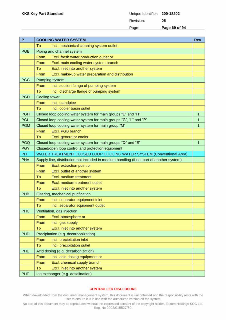
KKS Key Part Standard Unique Identifier: 200-18202
Revision: 05
Page: Page 69 of 94
CONTROLLED DISCLOSURE
When downloaded from the document management system, this document is uncontrolled and the responsibility rests with the user to ensure it is in line with the authorized version on the system.
No part of this document may be reproduced without the expressed consent of the copyright holder, Eskom Holdings SOC Ltd,
Reg. No 2002/015527/30.
P COOLING WATER SYSTEM Rev
To Incl. mechanical cleaning system outlet
PGB Piping and channel system
From Excl. fresh water production outlet or
From Excl. main cooling water system branch
To Excl. inlet into another system
From Excl. make-up water preparation and distribution
PGC Pumping system
From Incl. suction flange of pumping system
To Incl. discharge flange of pumping system
PGD Cooling tower
From Incl. standpipe
To Incl. cooler basin outlet
PGH Closed loop cooling water system for main groups “E” and “H” 1
PGL Closed loop cooling water system for main groups “G”, “L” and “P” 1
PGM Closed loop cooling water system for main group “M” 1
From Excl. PGB branch
To Excl. generator cooler
PGQ Closed loop cooling water system for main groups “Q” and “S” 1
PGY Closed/open loop control and protection equipment
PH WATER TREATMENT CLOSED LOOP COOLING WATER SYSTEM (Conventional Area)
PHA Supply line, distribution not included in medium handling (if not part of another system)
From Excl. extraction point or
From Excl. outlet of another system
To Excl. medium treatment
From Excl. medium treatment outlet
To Excl. inlet into another system
PHB Filtering, mechanical purification
From Incl. separator equipment inlet
To Incl. separator equipment outlet
PHC Ventilation, gas injection
From Excl. atmosphere or
From Incl. gas supply
To Excl. inlet into another system
PHD Precipitation (e.g. decarbonization)
From Incl. precipitation inlet
To Incl. precipitation outlet
PHE Acid dosing (e.g. decarbonization)
From Incl. acid dosing equipment or
From Excl. chemical supply branch
To Excl. inlet into another system
PHF Ion exchanger (e.g. desalination)

KKS Key Part Standard Unique Identifier: 200-18202
Revision: 05
Page: Page 70 of 94
CONTROLLED DISCLOSURE
When downloaded from the document management system, this document is uncontrolled and the responsibility rests with the user to ensure it is in line with the authorized version on the system.
No part of this document may be reproduced without the expressed consent of the copyright holder, Eskom Holdings SOC Ltd,
Reg. No 2002/015527/30.
P COOLING WATER SYSTEM Rev
From Incl. ion exchanger inlet and
From Incl. chemical supply isolating valve, auxiliary medium supply to ion exchanger
To Incl. ion exchanger outlet
PHG Evaporation (e.g. desalination)
From Incl. feedwater inlet
To Incl. steam outlet and
From Incl. hot steam inlet
To Incl. condensate outlet
PHH Degasification, drying
From Incl. degasifier tank inlet
To Incl. tank outlet including heating equipment for steam condenser
PHJ Heating, cooling
From Incl. heater, cooler inlet
To Incl. heater, cooler outlet
PHK Internal piping, intermediate storage, pump system for main medium
Internal piping:
From Excl. outlet of another system
To Excl. inlet into another system
To Incl. medium treatment outlet
Intermediate storage:
From Incl. inlet, intermediate storage
To Incl. outlet, intermediate storage
Pump system:
From Incl. suction flange of pumping system
To Incl. discharge flange of pumping system
PHL Storage not included in medium treatment (and not part of another system)
From Incl. storage plant inlet
To Incl. storage plant outlet
PHN Chemical supply system
From Incl. extraction point or
From Incl. storage tank
To Excl. transfer into another system
PHP Regeneration and purging equipment
From Incl. system inlet
To Excl. injection into another system
From Excl. chemical supply, auxiliary medium supply and purging air supply
To Incl. regeneration purging equipment
PHQ Injection device for main medium
From Incl. injection device or
From Excl. chemical supply junction
To Incl. inlet into another system

KKS Key Part Standard Unique Identifier: 200-18202
Revision: 05
Page: Page 71 of 94
CONTROLLED DISCLOSURE
When downloaded from the document management system, this document is uncontrolled and the responsibility rests with the user to ensure it is in line with the authorized version on the system.
No part of this document may be reproduced without the expressed consent of the copyright holder, Eskom Holdings SOC Ltd,
Reg. No 2002/015527/30.
P COOLING WATER SYSTEM Rev
PHR Flushing water and residue removal including neutralization
From Excl. outlet of respective system
To Excl. transfer point of another system
PHS Sludge thickener
From Excl. outlet of respective system
To Excl. transfer point of another system
PHT Heating, cooling and flushing medium distribution
From Incl. heating, cooling and flushing medium production
From Excl. heating, cooling and flushing medium supply junction
To Excl. consumer and
From Excl. consumer
PHX Control medium supply for closed/open loop control and protection equipment
PHY Closed/open loop control and protection equipment
PU COMMON EQUIPMENT FOR COOLING WATER SYSTEM
PUN Dosing equipment
PY CLOSED/OPEN LOOP CONTROL AND PROTECTION EQUIPMENT INCLUDING ELECTRICAL SUPPLY FOR COOLING WATER SYSTEM
PYA Control desk in control room
PYB Control panel in control room
PYC Local control panel, desk and solenoid operated valve panel
PYG Marshaling panel
PYH Measurement rack
PYJ VSD Field equipment panels 2
PYK DC supply including associated equipment
PYL AC supply and distribution
PYQ Computer equipment

KKS Key Part Standard Unique Identifier: 200-18202
Revision: 05
Page: Page 72 of 94
CONTROLLED DISCLOSURE
When downloaded from the document management system, this document is uncontrolled and the responsibility rests with the user to ensure it is in line with the authorized version on the system.
No part of this document may be reproduced without the expressed consent of the copyright holder, Eskom Holdings SOC Ltd,
Reg. No 2002/015527/30.
A.10 Q – Auxiliary System
Q AUXILIARY SYSTEM Rev
QC CENTRAL CHEMICAL SUPPLY
QE GENERAL COMPRESSED AND TRANSFER AIR SUPPLY
QEA Central compressed and transfer air generation
QEB Central compressed and transfer air distribution and storage (air receiver)
QEH Service air supply system for main group H 1
QEL Service air supply system for main group G, P and L (for water supply, water/steam cycle and cooling water system)
QEM Service air supply system for main group M (for main machine set)
QEQ Service air supply system for main group Q (for auxiliaries)
QES Service air supply system for main group S (for ancillary systems)
QET Production and distribution of limestone powder carrier air 1
QF GENERAL CONTROL AIR SUPPLY
QFA Central control air generation
QFB Central control air distribution system
QFC General control air supply 1
QFE Control air supply system for main group E 1
QFH Control air supply system for main group H 1
QFL Control air supply system for main group G, P and L (for water supply, water/steam cycle and cooling water system)
1
QFM Control air supply system for main group M (main machine set) 1
QFQ Control air supply system for main group Q (for auxiliaries) 1
QFS Control air supply system for main group S (for ancillary systems) 1
QFY Control and Protection equipment 1
QG CENTRAL GAS SUPPLY FOR CLOSED GAS CYCLE (AS WORKING MEDIUM)
QGA Electrolyser
QGB Gas cooling equipment
QGC Gas processing equipment
QGD Gas scrubber
QGE Gas holder
QGF Gas compressor
QGG Gas purifier
QGH Gas drier
QGJ Storage tank
QGK Gas circulation control
QGL Bottle filling station
QGM Gas mixing station
QGN Pressure reducing station
QGP Purging gas station
QGQ Water treatment station
QGR Electrolyte station

KKS Key Part Standard Unique Identifier: 200-18202
Revision: 05
Page: Page 73 of 94
CONTROLLED DISCLOSURE
When downloaded from the document management system, this document is uncontrolled and the responsibility rests with the user to ensure it is in line with the authorized version on the system.
No part of this document may be reproduced without the expressed consent of the copyright holder, Eskom Holdings SOC Ltd,
Reg. No 2002/015527/30.
Q AUXILIARY SYSTEM Rev
QGS Control/measurement
QGT Piping system for condensate/sewage
QGU Piping system for hydrogen/oxygen
QGV Piping system for feedwater
QGW Piping system for cooling water
QGX Piping system for electrolyte
QGY Control and instrumentation use
QH AUXILIARY STEAM GENERATION
QHA Pressure system
QHB Supporting structure casing, steam generator combustion chamber
QHC Cleaning equipment for the heating surfaces on the flue gas side
QHD Ash and slag handling
QHE Sludge, expansion, drainage system
QHF Bunker, feeder, pulverizing system
QHG Boiler water circulation (electrically heated steam generator)
QHH Main firing (electrically heated steam generator)
QHJ Lighting-up system (in case the mentioned functions are independent)
QHL Combustion air system (forced draught)
QHM Gas heating system (for closed system)
QHN Flue gas exhaust (induced draught, without flue gas treatment)
QHP Mechanical dust separation (cylone)
QHQ Electrostatic precipitator
QHR Chemical flue gas treatment system incl. residue removal (absortive process)
QHS Chemical flue gas treatment system incl. residue removal (catalytic process)
QHT Chemical flue gas treatment system incl. residue removal (absortive process)
QHU Flue gas reheating
QHX Control medium supply for closed/open loop control and protection equipment
QHY Closed/open loop control and protection equipment
QJ CENTRAL GAS SUPPLY (INCL. INERT GAS)
QJA Central gas supply 1
QJB Gas supply and distribution system O2 (oxygen) 1
QJD Gas supply and distribution system N2 (nitrogen) 1
QJE Gas generation system N2 (nitrogen) 1
QJF Gas supply and distribution system H2 (hydrogen) 1
QJG Central gas supply, gas generation system H2 (hydrogen) 1
QJH Gas supply and distribution system CH4 (methane) 1
QJK Gas supply and distribution system CO2 (carbon dioxide) 1
QJM Gas supply and distribution system C2H2 (acetylene) 1
QJN Gas supply and distribution system He (helium) 1
QJP Gas supply and distribution system C3H8 (propane gas) 1
QJQ Gas supply and distribution system AR (argon) 1
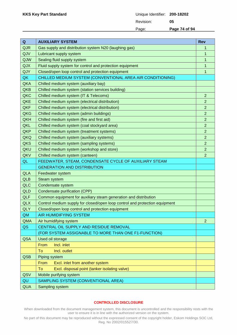
KKS Key Part Standard Unique Identifier: 200-18202
Revision: 05
Page: Page 74 of 94
CONTROLLED DISCLOSURE
When downloaded from the document management system, this document is uncontrolled and the responsibility rests with the user to ensure it is in line with the authorized version on the system.
No part of this document may be reproduced without the expressed consent of the copyright holder, Eskom Holdings SOC Ltd,
Reg. No 2002/015527/30.
Q AUXILIARY SYSTEM Rev
QJR Gas supply and distribution system N20 (laughing gas) 1
QJV Lubricant supply system 1
QJW Sealing fluid supply system 1
QJX Fluid supply system for control and protection equipment 1
QJY Closed/open loop control and protection equipment 1
QK CHILLED MEDIUM SYSTEM (CONVENTIONAL AREA AIR CONDITIONING)
QKA Chilled medium system (auxiliary bay)
QKB Chilled medium system (station services building)
QKC Chilled medium system (IT & Telecoms) 2
QKE Chilled medium system (electrical distribution) 2
QKF Chilled medium system (electrical distribution) 2
QKG Chilled medium system (admin buildings) 2
QKH Chilled medium system (fire and first aid) 2
QKL Chilled medium system (coal stockyard area) 2
QKP Chilled medium system (treatment systems) 2
QKQ Chilled medium system (auxiliary systems) 2
QKS Chilled medium system (sampling systems) 2
QKU Chilled medium system (workshop and store) 2
QKV Chilled medium system (canteen) 2
QL FEEDWATER, STEAM, CONDENSATE CYCLE OF AUXILIARY STEAM
GENERATION AND DISTRIBUTION
QLA Feedwater system
QLB Steam system
QLC Condensate system
QLD Condensate purification (CPP)
QLF Common equipment for auxiliary steam generation and distribution
QLX Control medium supply for closed/open loop control and protection equipment
QLY Closed/open loop control and protection equipment
QM AIR HUMIDIFYING SYSTEM
QMA Air humidifying system 2
QS CENTRAL OIL SUPPLY AND RESIDUE REMOVAL
(FOR SYSTEM ASSIGNABLE TO MORE THAN ONE F1-FUNCTION)
QSA Used oil storage
From Incl. inlet
To Incl. outlet
QSB Piping system
From Excl. inlet from another system
To Excl. disposal point (tanker isolating valve)
QSV Mobile purifying system
QU SAMPLING SYSTEM (CONVENTIONAL AREA)
QUA Sampling system

KKS Key Part Standard Unique Identifier: 200-18202
Revision: 05
Page: Page 75 of 94
CONTROLLED DISCLOSURE
When downloaded from the document management system, this document is uncontrolled and the responsibility rests with the user to ensure it is in line with the authorized version on the system.
No part of this document may be reproduced without the expressed consent of the copyright holder, Eskom Holdings SOC Ltd,
Reg. No 2002/015527/30.
Q AUXILIARY SYSTEM Rev
QUG Sampling system Water Treatment Plant 1
QUL Sampling system Steam, Water, Gas Cycle 1
QUT Auxiliary boiler sample rack system 2
QUY Closed/open loop control and protection equipment

KKS Key Part Standard Unique Identifier: 200-18202
Revision: 05
Page: Page 76 of 94
CONTROLLED DISCLOSURE
When downloaded from the document management system, this document is uncontrolled and the responsibility rests with the user to ensure it is in line with the authorized version on the system.
No part of this document may be reproduced without the expressed consent of the copyright holder, Eskom Holdings SOC Ltd,
Reg. No 2002/015527/30.
A.11 S – Ancillary System
S ANCILLARY SYSTEM Rev
SA VENTILATION SYSTEM (CONVENTIONAL AREA) (AIR CONDITIONING)
SAA Auxiliary bay
SAB Boiler bay
SAC Control building (access)
SAD Outside plant control room
SAE Electrical distribution
SAF HV yard building 2
SAG Admin building (system)
SAH Fire and first aid building
SAJ Condensate polishing plant
SAK Cable tunnel (ventilation)
SAL Coal stockyard
SAM Ash dump
SAN Telecommunication building
SAP Treatment Systems 1
SAQ Auxiliary systems 2
SAS Station services building
SAT Turbine hall
SAU Workshop and store
SAV Canteen 2
SAY Control panel
SB HEATING SYSTEM (BUILDING RELATED)
SC COMPRESSED AIR SUPPLY SYSTEM (PERMANENT INSTALLATION)
SCA Compressed air generation
SCB Compressed air distribution
SCC Compressed air storage (air receiver)
SCE Stationary compressed air distribution – Main group M 2
SCH Stationary compressed air distribution – Main group H 2
SD CLEANING SYSTEM (DECONTAMINATION SYSTEM SEE ‘FK’) (PERMANENT INSTALLATION)
SDA Dust collection equipment, conventional fuel supply system
SDC Dust collection equipment, fuel disposal system
SDE Dust collection equipment, floor
SDR Condenser cleaning equipment 2
SE WELDING GAS SYSTEM (PERMANENT INSTALLATION)
SEA Welding gas system 2
SG FIRE PROTECTION SYSTEM (PERMANENT INSTALLATION)
SGA Firefighting water system (conventional area)
SGC Spray water equipment (conventional area)
SGE Sprinkler equipment

KKS Key Part Standard Unique Identifier: 200-18202
Revision: 05
Page: Page 77 of 94
CONTROLLED DISCLOSURE
When downloaded from the document management system, this document is uncontrolled and the responsibility rests with the user to ensure it is in line with the authorized version on the system.
No part of this document may be reproduced without the expressed consent of the copyright holder, Eskom Holdings SOC Ltd,
Reg. No 2002/015527/30.
S ANCILLARY SYSTEM Rev
SGF Foam firefighting equipment
SGG Tank casing cooling equipment
SGJ CO2 firefighting equipment
SGK Halon firefighting equipment
SGL Powder firefighting equipment
SGM Firefighting water system (conventional area) 5
SGX Control medium supply for closed/open loop control and protection equipment
SGY Closed/open loop control and protection equipment
SM OVERHEAD CRANE, PERMANENT HOIST AND LIFTING DEVICE
SMA Auxiliary cooling system crane
SMB Ash plant crane
SMC Store crane
SMD Workshop crane
SME Water supply and discharge plant crane
SMF Boiler house crane
SMG Auxiliary bay crane
SMH Auxiliary crane (incl. ‘A’ frame)
SMJ Cooling system crane and hoist
SMK Coal plant crane and hoist
SML Low pressure services crane
SMM Compressor house crane 2
SMT Turbine house crane
SN ELEVATOR INSTALLATION
SNA Auxiliary bay lift
SNB Boiler house lift
SNC Cooling tower lift
SND Coal silo lift
SNE Smoke stack lift
SNF Station services building lift
SNG Workshop and stores lift
SNH Ash plant lift
SNJ Main admin building lift 5
SP RAILWAY INSTALLATION/PERMANENT WAY
SPA Railway installation
SQ ROAD TRAFFIC INSTALLATION
SQA Road traffic installation
ST WORKSHOP, STORE AND LABORATORY EQUIPMENT AND SOCIAL INSTALLATION OUTSIDE CONTROLLED AREA
STA Facilities for workshop
STC Decentralized maintenance workshop
STE Facilities for store, fuel station (garage)

KKS Key Part Standard Unique Identifier: 200-18202
Revision: 05
Page: Page 78 of 94
CONTROLLED DISCLOSURE
When downloaded from the document management system, this document is uncontrolled and the responsibility rests with the user to ensure it is in line with the authorized version on the system.
No part of this document may be reproduced without the expressed consent of the copyright holder, Eskom Holdings SOC Ltd,
Reg. No 2002/015527/30.
S ANCILLARY SYSTEM Rev
STG Facilities for laboratory
STP Social installation

KKS Key Part Standard Unique Identifier: 200-18202
Revision: 05
Page: Page 79 of 94
CONTROLLED DISCLOSURE
When downloaded from the document management system, this document is uncontrolled and the responsibility rests with the user to ensure it is in line with the authorized version on the system.
No part of this document may be reproduced without the expressed consent of the copyright holder, Eskom Holdings SOC Ltd,
Reg. No 2002/015527/30.
A.12 U – Structure
U STRUCTURE Rev
UA STRUCTURE FOR NETWORK AND DISTRIBUTION PLANT
UAA Structure for outdoor switchgear equipment
UAB System switchgear building
UAC Grid control centre
UAD HV yard area
UAE Structure for control air system
UAG Structure for transformer
UAH Structure for plinths and instrument
UAX Special structure (plant associated)
UAY Structure for bridge
UAZ Structure for duct
UB STRUCTURE FOR POWER STATION ELECTRICAL POWER SYSTEM
UBA Switchgear building
UBB Switchgear building
UBC Structure for station transformer
UBD Structure for LV unit auxiliary supply transformer
UBE Structure for HV unit auxiliary supply transformer
UBF Structure for generator transformer
UBG Structure for start-up transformer
UBH Oil separating and collecting pit
UBJ Transformer track
UBK Service building (transformer, erecting structure)
UBL Structure for busbar
UBM Structure for transformer cooling system
UBN Structure for emergency power generator set (without central chilled water plant)
UBP Structure for emergency power generator set and central chilled water plant
UBQ Structure for fuel supply for emergency power generator
UBR Substation for direct/indirect dry cooling
UBS Substation for coal, ash and bulk fuel plant
UBT Substation for precipitator
UBU Structure for power transmission and auxiliary power supply 2
UBV Structure for power transmission and auxiliary power supply 2
UBW Structure for power transmission and auxiliary power supply 2
UBX Special structure (auxiliary bay)
UBY Structure for bridge
UBZ Structure for duct
UC STRUCTURE FOR CONTROL AND INSTRUMENTATION EQUIPMENT
UCA Unit control room building
UCB Station control building, HV yard control building
UCC Structure for IT and telecoms 2
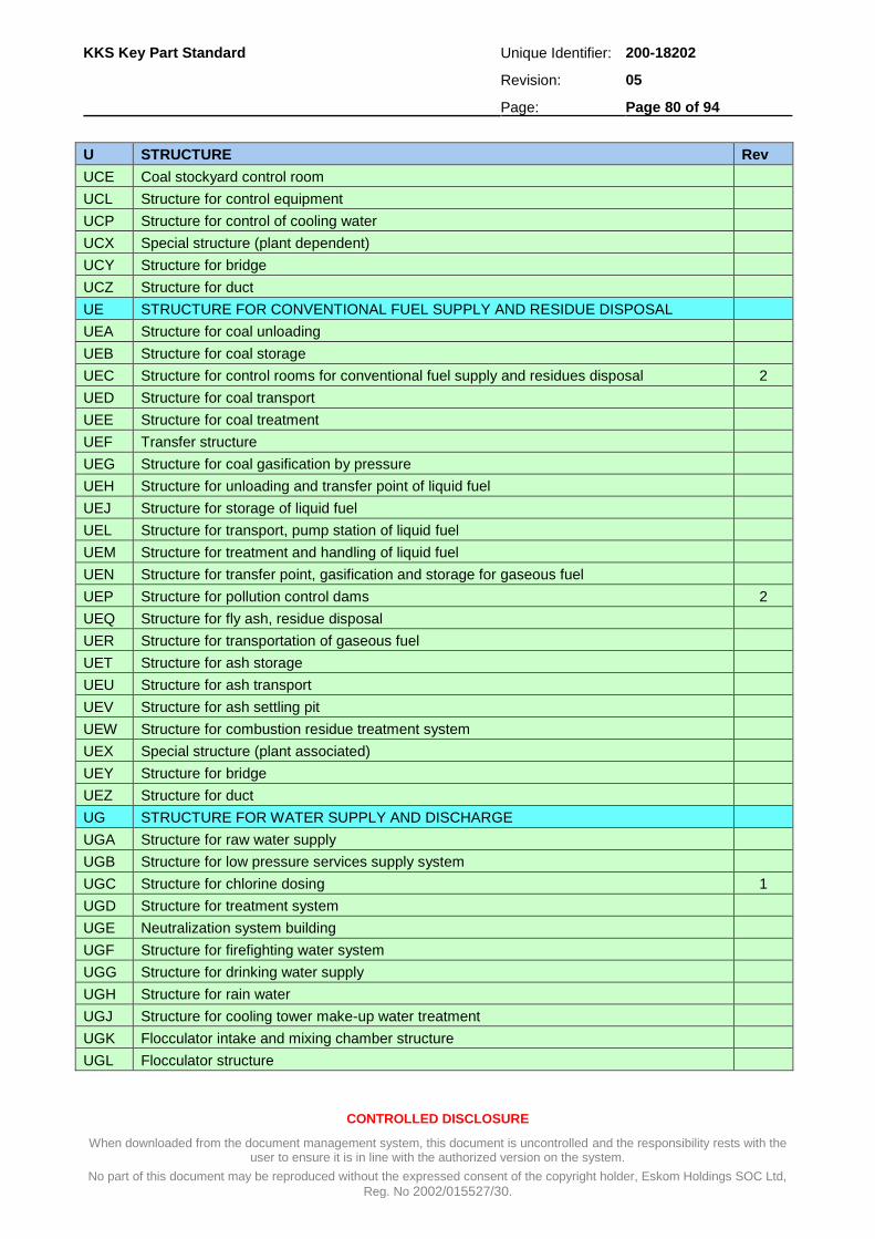
KKS Key Part Standard Unique Identifier: 200-18202
Revision: 05
Page: Page 80 of 94
CONTROLLED DISCLOSURE
When downloaded from the document management system, this document is uncontrolled and the responsibility rests with the user to ensure it is in line with the authorized version on the system.
No part of this document may be reproduced without the expressed consent of the copyright holder, Eskom Holdings SOC Ltd,
Reg. No 2002/015527/30.
U STRUCTURE Rev
UCE Coal stockyard control room
UCL Structure for control equipment
UCP Structure for control of cooling water
UCX Special structure (plant dependent)
UCY Structure for bridge
UCZ Structure for duct
UE STRUCTURE FOR CONVENTIONAL FUEL SUPPLY AND RESIDUE DISPOSAL
UEA Structure for coal unloading
UEB Structure for coal storage
UEC Structure for control rooms for conventional fuel supply and residues disposal 2
UED Structure for coal transport
UEE Structure for coal treatment
UEF Transfer structure
UEG Structure for coal gasification by pressure
UEH Structure for unloading and transfer point of liquid fuel
UEJ Structure for storage of liquid fuel
UEL Structure for transport, pump station of liquid fuel
UEM Structure for treatment and handling of liquid fuel
UEN Structure for transfer point, gasification and storage for gaseous fuel
UEP Structure for pollution control dams 2
UEQ Structure for fly ash, residue disposal
UER Structure for transportation of gaseous fuel
UET Structure for ash storage
UEU Structure for ash transport
UEV Structure for ash settling pit
UEW Structure for combustion residue treatment system
UEX Special structure (plant associated)
UEY Structure for bridge
UEZ Structure for duct
UG STRUCTURE FOR WATER SUPPLY AND DISCHARGE
UGA Structure for raw water supply
UGB Structure for low pressure services supply system
UGC Structure for chlorine dosing 1
UGD Structure for treatment system
UGE Neutralization system building
UGF Structure for firefighting water system
UGG Structure for drinking water supply
UGH Structure for rain water
UGJ Structure for cooling tower make-up water treatment
UGK Flocculator intake and mixing chamber structure
UGL Flocculator structure
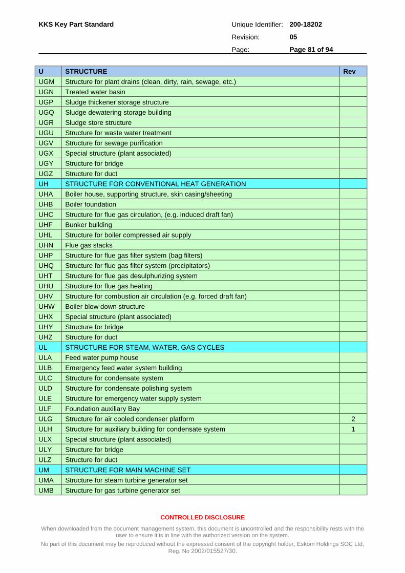
KKS Key Part Standard Unique Identifier: 200-18202
Revision: 05
Page: Page 81 of 94
CONTROLLED DISCLOSURE
When downloaded from the document management system, this document is uncontrolled and the responsibility rests with the user to ensure it is in line with the authorized version on the system.
No part of this document may be reproduced without the expressed consent of the copyright holder, Eskom Holdings SOC Ltd,
Reg. No 2002/015527/30.
U STRUCTURE Rev
UGM Structure for plant drains (clean, dirty, rain, sewage, etc.)
UGN Treated water basin
UGP Sludge thickener storage structure
UGQ Sludge dewatering storage building
UGR Sludge store structure
UGU Structure for waste water treatment
UGV Structure for sewage purification
UGX Special structure (plant associated)
UGY Structure for bridge
UGZ Structure for duct
UH STRUCTURE FOR CONVENTIONAL HEAT GENERATION
UHA Boiler house, supporting structure, skin casing/sheeting
UHB Boiler foundation
UHC Structure for flue gas circulation, (e.g. induced draft fan)
UHF Bunker building
UHL Structure for boiler compressed air supply
UHN Flue gas stacks
UHP Structure for flue gas filter system (bag filters)
UHQ Structure for flue gas filter system (precipitators)
UHT Structure for flue gas desulphurizing system
UHU Structure for flue gas heating
UHV Structure for combustion air circulation (e.g. forced draft fan)
UHW Boiler blow down structure
UHX Special structure (plant associated)
UHY Structure for bridge
UHZ Structure for duct
UL STRUCTURE FOR STEAM, WATER, GAS CYCLES
ULA Feed water pump house
ULB Emergency feed water system building
ULC Structure for condensate system
ULD Structure for condensate polishing system
ULE Structure for emergency water supply system
ULF Foundation auxiliary Bay
ULG Structure for air cooled condenser platform 2
ULH Structure for auxiliary building for condensate system 1
ULX Special structure (plant associated)
ULY Structure for bridge
ULZ Structure for duct
UM STRUCTURE FOR MAIN MACHINE SET
UMA Structure for steam turbine generator set
UMB Structure for gas turbine generator set

KKS Key Part Standard Unique Identifier: 200-18202
Revision: 05
Page: Page 82 of 94
CONTROLLED DISCLOSURE
When downloaded from the document management system, this document is uncontrolled and the responsibility rests with the user to ensure it is in line with the authorized version on the system.
No part of this document may be reproduced without the expressed consent of the copyright holder, Eskom Holdings SOC Ltd,
Reg. No 2002/015527/30.
U STRUCTURE Rev
UMC Turbine foundation 2
UME Structure for water turbine generator set
UMG Structure for storage pumping set
UMJ Structure for diesel set
UMM Structure for compressor system
UMR Structure for gas engine plant
UMV Structure for turbine lubrication oil storage 2
UMX Special structure (plant)
UMY Structure for bridge
UMZ Structure for duct
UN STRUCTURE FOR PROCESS ENERGY PREPARATION FOR USERS OUTSIDE POWER PLANT
UNX Special structure (plant associated)
UNY Structure for bridge
UNZ Structure for duct
UP STRUCTURE FOR COOLING WATER SYSTEM (e.g. COOLING WATER INTAKE)
UPA Cooling water intake structure
UPB Service cooling water intake structure (closed loop)
UPC Cooling water intake structure
UPD Service cooling water intake structure (closed loop)
UPH Structure for cooling water treatment
UPJ Structure for service cooling water treatment (closed loop)
UPN Cooling water intake channel
UPP Service cooling water intake channel
UPQ Biocide treatment building
UPS Flushing water channel
UPT Flushing water treatment structure
UPX Special structure (plant)
UPY Structure for bridge
UPZ Structure for duct
UQ STRUCTURE FOR COOLING WATER SYSTEM (e.g. COOLING WATER PUMPING AND DISCHARGE)
UQA Cooling water pumphouse structure
UQB Service cooling water pumphouse structure (closed loop)
UQG Cooling water overflow structure, surge
UQH Flushing water discharge channel
UQJ Cooling water sealing pit incl. cooling water aeration
UQK Cooling water aeration structure
UQL Intermediate reservoir for service cooling water (closed loop)
UQM Service cooling water collecting pit (closed loop)
UQN Cooling water discharge channel
UQP Service cooling water discharge channel (closed loop)

KKS Key Part Standard Unique Identifier: 200-18202
Revision: 05
Page: Page 83 of 94
CONTROLLED DISCLOSURE
When downloaded from the document management system, this document is uncontrolled and the responsibility rests with the user to ensure it is in line with the authorized version on the system.
No part of this document may be reproduced without the expressed consent of the copyright holder, Eskom Holdings SOC Ltd,
Reg. No 2002/015527/30.
U STRUCTURE Rev
UQQ Cooling water discharge structure
UQR Service cooling water discharge (closed loop)
UQS Cooling water discharge channel
UQT Service cooling water discharge channel (closed loop)
UQU Cooling water weir structure, incl. cooling water aeration
UQV Structure for artificial aeration of cooling water
UQW Guide structure of cooling water channel
UQX Special structure (plant associated)
UQY Structure for bridge
UQZ Structure for duct
UR STRUCTURE FOR COOLING WATER SYSTEM (E.G. RECIRCULATION COOLING)
URA Cooling tower structure (main cooling water)
URB Cooling tower structure (service cooling water)
URC Structure for direct cooling system (e.g. air cooled condenser structure
URD Cooling tower pumphouse structure (main cooling water)
URE Cooling tower pumphouse structure (service cooling water)
URG Cooling tower connecting structure
URH Cooling tower discharge structure
URJ Cooling tower discharge channel
URK Cooling tower discharge structure
URL Cooling tower discharge channel
URM Cooling water supply structure
URN Cooling tower bypass structure
URP Cooling tower overflow structure
URQ Cooling tower overflow channel
URX Special structure (plant associated)
URY Structure for bridge
URZ Structure for duct
US STRUCTURE FOR ANCILLARY SYSTEM
USA Structure for air ventilation system
USB Structure for heating plant
USC Structure for compressed air supply
USG Fire pump house structure
USL Building for low pressure services Pump House
USR Structure for weather tower
USS Structure for Ancillary system (radio tower)
UST Workshop building
USU Store building
USV Laboratory building
USX Special structure (plant associated)
USY Structure for bridge

KKS Key Part Standard Unique Identifier: 200-18202
Revision: 05
Page: Page 84 of 94
CONTROLLED DISCLOSURE
When downloaded from the document management system, this document is uncontrolled and the responsibility rests with the user to ensure it is in line with the authorized version on the system.
No part of this document may be reproduced without the expressed consent of the copyright holder, Eskom Holdings SOC Ltd,
Reg. No 2002/015527/30.
U STRUCTURE Rev
USZ Structure for duct
UT STRUCTURE FOR AUXILIARY SYSTEM
UTA Supply system, building for several auxiliary system
UTB Central chilled water system building (air conditioning)
UTF Structure for compressor
UTG Central gas supply (no fuel supply)
UTH Auxiliary boiler building
UTJ Auxiliary boiler stack
UTM Structure for gas storage 2
UTS Chemical storage tank
UTV Recovered used oil storage and treatment 1
UTX Special structure (plant associated)
UTY Structure for bridge
UTZ Structure for duct
UV STRUCTURE FOR CHEMICAL FLUE GAS TREATMENT INCL. RESIDUE
REMOVAL (FOR ‘HR’, ‘HS’ AND ‘HT’)
UVA Structure for flue gas side heat exchanger
UVB Structure for flue gas fan system
UVC Structure for flue gas scrubber, reactor
UVD Structure for absorbent/absorbent circuit
UVE Structure for reagent supply incl. preparation/treatment, storage, forwarding
UVG Structure for chemical flue gas treatment 1
UVF Structure for thickening and solids dewatering, solids drying and compacting system
UVH Structure for (solids/product) forwarding, storage, loading
UVJ Structure for chemical flue gas treatment incl. residues removal (for HR, HS, HT) 2
UVM Structure for catalyst handling and storage 2
UVN Structure for chemical flue gas treatment incl. residues removal (for HR, HS, HT) 2
UVX Special structure (plant specific)
UVY Bridge structure
UVZ Ducting structure
UX STRUCTURE FOR EXTERNAL SYSTEM (POWER PLANT ASSOCIATED)
UXB Structure for Gas Turbine Generator Sets
UXX Special structure (plant associated)
UXY Structure for bridge
UXZ Structure for duct
UY GENERAL SERVICE STRUCTURE
UYA Staff facility and office building
UYB Staff facility building
UYC Administration building
UYD Canteen
UYE Gate house

KKS Key Part Standard Unique Identifier: 200-18202
Revision: 05
Page: Page 85 of 94
CONTROLLED DISCLOSURE
When downloaded from the document management system, this document is uncontrolled and the responsibility rests with the user to ensure it is in line with the authorized version on the system.
No part of this document may be reproduced without the expressed consent of the copyright holder, Eskom Holdings SOC Ltd,
Reg. No 2002/015527/30.
U STRUCTURE Rev
UYF Control gate house
UYG Building for visitor information
UYH Training facility
UYJ Building for medical supply
UYL Security fence control building
UYN Locomotive shed
UYP Structure for fire prevention equipment
UYQ Garage building
UYR Car workshop
UYS Service station
UYV Seismic Station
UYX Special structure (plant associated)
UYY Structure for bridge
UYZ Structure for duct
UZ STRUCTURE FOR TRANSPORT, TRAFFIC, FENCING, GARDENS AND OTHER PURPOSES
UZA Plant streets and roads (incl. affiliated structure)
UZC Court yard
UZD Parking area
UZE Structure for railway installation
UZF Structure for crane and lifting equipment
UZJ Fencing and gate
UZK Site gardening and equipment (incl. structure)
UZL Structure for noise reduction
UZM Protection structure against external influences
UZN Structure for flood water protection
UZP Structure for quay protection
UZQ Structure for regulation of the river
UZR Harbour structure
UZS Jetty
UZT Aircraft landing field, outdoor area
UZU Structure for area safety - dog kennel
UZV Site preparation 1
UZW Housing, residential area
UZX Special structure (plant associated)
UZY Structure for bridge
UZZ Structure for duct
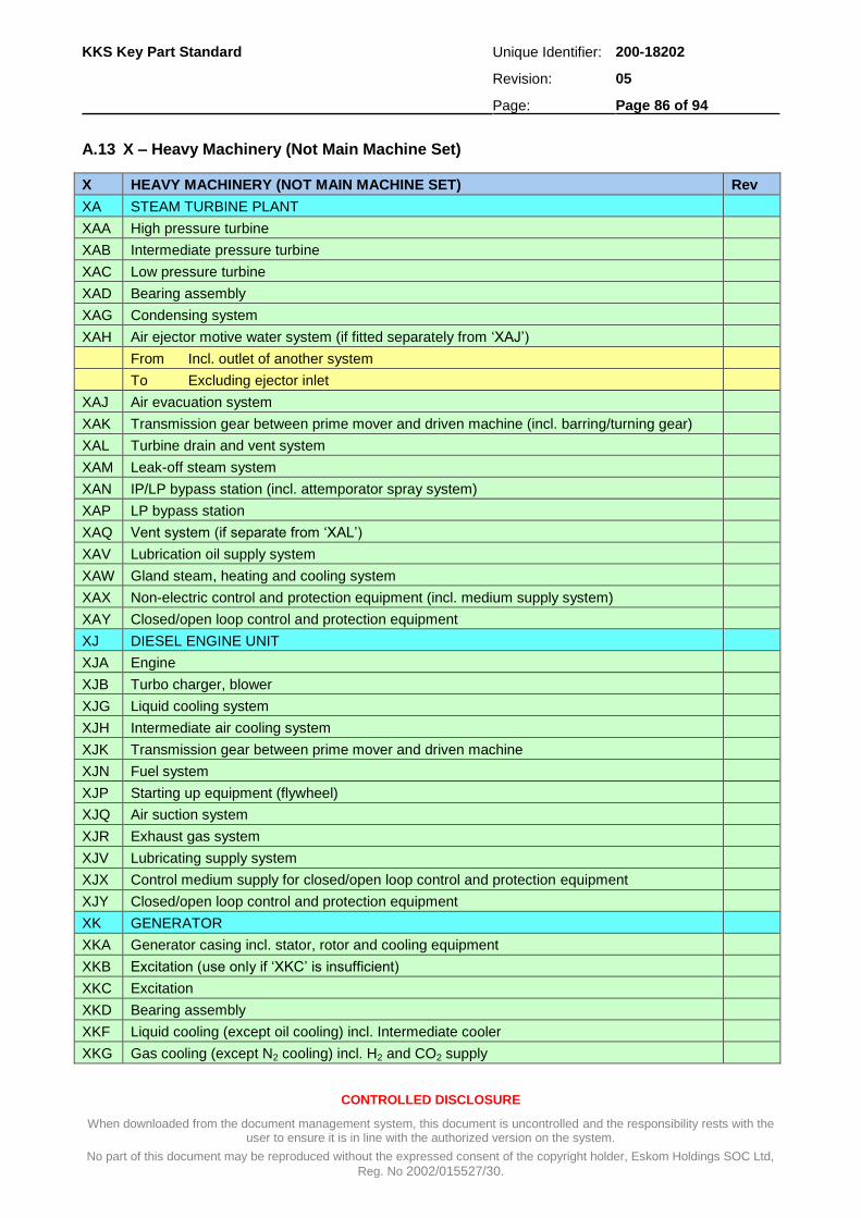
KKS Key Part Standard Unique Identifier: 200-18202
Revision: 05
Page: Page 86 of 94
CONTROLLED DISCLOSURE
When downloaded from the document management system, this document is uncontrolled and the responsibility rests with the user to ensure it is in line with the authorized version on the system.
No part of this document may be reproduced without the expressed consent of the copyright holder, Eskom Holdings SOC Ltd,
Reg. No 2002/015527/30.
A.13 X – Heavy Machinery (Not Main Machine Set)
X HEAVY MACHINERY (NOT MAIN MACHINE SET) Rev
XA STEAM TURBINE PLANT
XAA High pressure turbine
XAB Intermediate pressure turbine
XAC Low pressure turbine
XAD Bearing assembly
XAG Condensing system
XAH Air ejector motive water system (if fitted separately from ‘XAJ’)
From Incl. outlet of another system
To Excluding ejector inlet
XAJ Air evacuation system
XAK Transmission gear between prime mover and driven machine (incl. barring/turning gear)
XAL Turbine drain and vent system
XAM Leak-off steam system
XAN IP/LP bypass station (incl. attemporator spray system)
XAP LP bypass station
XAQ Vent system (if separate from ‘XAL’)
XAV Lubrication oil supply system
XAW Gland steam, heating and cooling system
XAX Non-electric control and protection equipment (incl. medium supply system)
XAY Closed/open loop control and protection equipment
XJ DIESEL ENGINE UNIT
XJA Engine
XJB Turbo charger, blower
XJG Liquid cooling system
XJH Intermediate air cooling system
XJK Transmission gear between prime mover and driven machine
XJN Fuel system
XJP Starting up equipment (flywheel)
XJQ Air suction system
XJR Exhaust gas system
XJV Lubricating supply system
XJX Control medium supply for closed/open loop control and protection equipment
XJY Closed/open loop control and protection equipment
XK GENERATOR
XKA Generator casing incl. stator, rotor and cooling equipment
XKB Excitation (use only if ‘XKC’ is insufficient)
XKC Excitation
XKD Bearing assembly
XKF Liquid cooling (except oil cooling) incl. Intermediate cooler
XKG Gas cooling (except N2 cooling) incl. H2 and CO2 supply
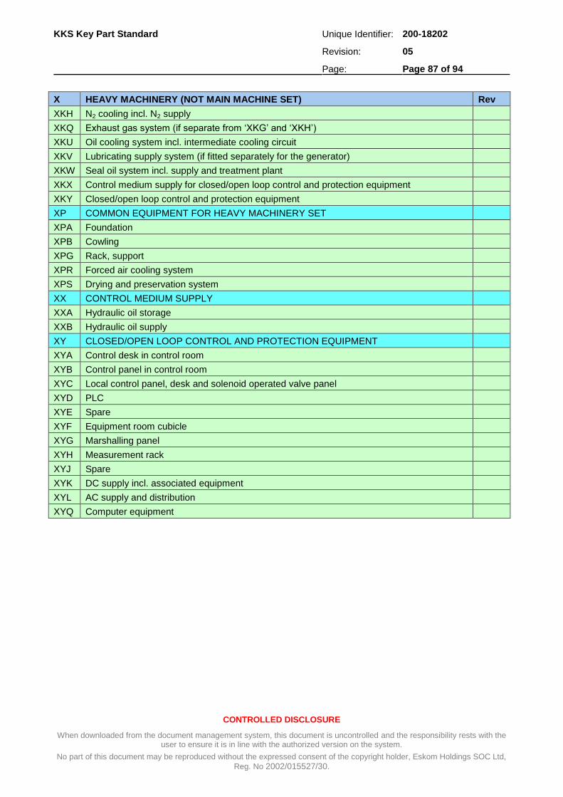
KKS Key Part Standard Unique Identifier: 200-18202
Revision: 05
Page: Page 87 of 94
CONTROLLED DISCLOSURE
When downloaded from the document management system, this document is uncontrolled and the responsibility rests with the user to ensure it is in line with the authorized version on the system.
No part of this document may be reproduced without the expressed consent of the copyright holder, Eskom Holdings SOC Ltd,
Reg. No 2002/015527/30.
X HEAVY MACHINERY (NOT MAIN MACHINE SET) Rev
XKH N2 cooling incl. N2 supply
XKQ Exhaust gas system (if separate from ‘XKG’ and ‘XKH’)
XKU Oil cooling system incl. intermediate cooling circuit
XKV Lubricating supply system (if fitted separately for the generator)
XKW Seal oil system incl. supply and treatment plant
XKX Control medium supply for closed/open loop control and protection equipment
XKY Closed/open loop control and protection equipment
XP COMMON EQUIPMENT FOR HEAVY MACHINERY SET
XPA Foundation
XPB Cowling
XPG Rack, support
XPR Forced air cooling system
XPS Drying and preservation system
XX CONTROL MEDIUM SUPPLY
XXA Hydraulic oil storage
XXB Hydraulic oil supply
XY CLOSED/OPEN LOOP CONTROL AND PROTECTION EQUIPMENT
XYA Control desk in control room
XYB Control panel in control room
XYC Local control panel, desk and solenoid operated valve panel
XYD PLC
XYE Spare
XYF Equipment room cubicle
XYG Marshalling panel
XYH Measurement rack
XYJ Spare
XYK DC supply incl. associated equipment
XYL AC supply and distribution
XYQ Computer equipment

KKS Key Part Standard Unique Identifier: 200-18202
Revision: 05
Page: Page 88 of 94
CONTROLLED DISCLOSURE
When downloaded from the document management system, this document is uncontrolled and the responsibility rests with the user to ensure it is in line with the authorized version on the system.
No part of this document may be reproduced without the expressed consent of the copyright holder, Eskom Holdings SOC Ltd,
Reg. No 2002/015527/30.
A.14 Second Breakdown Level Equipment Unit – Key
[1] [2] SECOND BREAKDOWN LEVEL EQUIPMENT UNIT - KEY [3]
[4] A [5] Mechanical equipment (machinery including driven or hand operated) [6]
[7] AA [8] Valve, damper including actuator, rupture disc, equipment, also manual, etc. [9]
[10] AB [11] Isolating element (access gates, doors, locks, etc.) [12]
[13] AC [14] Heat exchanger, heat transfer surface [15]
[16] AE [17] Turning, driving, lifting and slewing unit (manipulators also) [18]
[19] AF [20] Continuous conveyor unit (escalator) [21]
[22] AG [23] Generator unit [24]
[25] AH [26] Heating, cooling and air-conditioning unit [27]
[28] AJ [29] Size reduction equipment (crushing milling plant) [30]
[31] AK [32] Pressing and packaging unit [33]
[34] AM [35] Mixer, agitator, vibrating unit [36]
[37] AN [38] Compressor, fan and blower unit [39]
[40] AP [41] Pump unit [42]
[43] AS [44] Positioning and tensioning equipment number for non-electrical variable [45]
[46] AT [47] Purifying, drying, filtering, separating and screening unit, steam trap, equip. other than ‘BT’
[48]
[49] AU [50] Brake, coupling and gearbox unit, not electrical converter [51]
[52] AV [53] Combustion unit [54]
[55] AW
[56] Fixed workshop equipment [57]
[58] AX [59] Testing control and monitoring equipment (e.g. weighing devices) [60]
[61] AZ [62] blocked [63] 2
[64] B [65] MECHANICAL EQUIPMENT [66]
[67] BB [68] Storage equipment (vessel, tank, dam) [69]
[70] BE [71] Tunnel and trench (e.g. inspection/cable access) [72]
[73] BF [74] Foundation [75]
[76] BN [77] Ejector, injector, jet pump (attemporator) [78]
[79] BP [80] Flow restricting limiter, orifice (not for metering) [81]
[82] BQ [83] Hanger, support, frame, rack, pipe penetration, cable tray [84]
[85] BR [86] Piping, duct and channel [87]
[88] BS [89] Sound absorber (silencer) [90]
[91] BT [92] Flue gas catalytic converter module [93]
[94] BU [95] Insulation, cladding [96]
[97] BZ [98] blocked [99] 2
[100] C [101] DIRECT MEASURING CIRCUIT [102]
[103] CD [104] Density [105]
[106] CE [107] Electrical quantities (e.g. current, voltage, power, electrical frequency) [108]
[109] CF [110] Flow, mass flow [111]
[112] CG [113] Distance, length, position, direction of rotation [114]
[115] CH [116] Manual input (as manually operated sensor, e.g. fire detector) [117]

KKS Key Part Standard Unique Identifier: 200-18202
Revision: 05
Page: Page 89 of 94
CONTROLLED DISCLOSURE
When downloaded from the document management system, this document is uncontrolled and the responsibility rests with the user to ensure it is in line with the authorized version on the system.
No part of this document may be reproduced without the expressed consent of the copyright holder, Eskom Holdings SOC Ltd,
Reg. No 2002/015527/30.
[1] [2] SECOND BREAKDOWN LEVEL EQUIPMENT UNIT - KEY [3]
[118] CK [119] Time [120]
[121] CL [122] Level (also for dividing line) [123]
[124] CM [125] Humidity (moisture) [126]
[127] C [128] DIRECT MEASURING CIRCUIT [129]
[130] CP [131] Pressure [132]
[133] CQ [134] Quality quantities (analysis, material characteristic other than ‘CD’, ‘CM’ and ‘CV’)
[135]
[136] CR [137] Radiation quantities [138]
[139] CS [140] Rotational speed, velocity, frequency, acceleration (mechanical) [141]
[142] CT [143] Temperature [144]
[145] CU [146] Combined quantities [147]
[148] CV [149] Viscosity [150]
[151] CW [152] Weight, force, mass [153]
[154] CY [155] Vibration, expansion [156]
[157] D [158] CLOSED LOOP CONTROL CIRCUIT [159]
[160] DD [161] Density [162]
[163] DE [164] Electrical quantities (e.g. current, voltage, power, electrical frequency) [165]
[166] DF [167] Flow, mass flow [168]
[169] DG [170] Distance, length, position direction of rotation [171]
[172] DK [173] Time [174]
[175] DL [176] Level (also for dividing line) [177]
[178] DM [179] Humidity (moisture) [180]
[181] DP [182] Pressure [183]
[184] DQ [185] Quality quantities (analysis, material characteristic other than ‘DD’, ‘DM’ and ‘DV’)
[186]
[187] DR [188] Radiation quantities [189]
[190] DS [191] Rotational speed, velocity frequency, acceleration mechanical) [192]
[193] DT [194] Temperature [195]
[196] DU [197] Combined quantities [198]
[199] DV [200] Viscosity [201]
[202] DW [203] Weight, force, mass [204]
[205] DY [206] Vibration, expansion [207]
[208] E [209] ANALOGUE AND BINARY SIGNAL CONDITIONING [210]
[211] EA [212] Open loop control [213]
[214] EB [215] Open loop control [216]
[217] EC [218] Open loop control [219]
[220] ED [221] Open loop control [222]
[223] EE [224] Open loop control [225]
[226] EG [227] Alarm/annunciation [228]
[229] EH [230] Alarm/annunciation [231]
[232] EJ [233] Alarm/annunciation [234]

KKS Key Part Standard Unique Identifier: 200-18202
Revision: 05
Page: Page 90 of 94
CONTROLLED DISCLOSURE
When downloaded from the document management system, this document is uncontrolled and the responsibility rests with the user to ensure it is in line with the authorized version on the system.
No part of this document may be reproduced without the expressed consent of the copyright holder, Eskom Holdings SOC Ltd,
Reg. No 2002/015527/30.
[1] [2] SECOND BREAKDOWN LEVEL EQUIPMENT UNIT - KEY [3]
[235] EK [236] Alarm/annunciation [237]
[238] EM [239] Process computer (also for operating and monitoring) [240]
[241] EN [242] Process computer [243]
[244] EP [245] Process computer [246]
[247] EQ [248] Process computer [249]
[250] ER [251] Process computer [252]
[253] EU [254] Combined analogue and binary signal processing [255]
[256] EW [257] Protection [258]
[259] EX [260] Protection [261]
[262] EY [263] Protection [264]
[265] EZ [266] Protection [267]
[268] F [269] INDIRECT MEASURING CIRCUIT [270]
[271] FD [272] Density [273]
[274] FE [275] Electrical quantities (e.g. current, voltage, power, electrical frequency) [276]
[277] FF [278] Flow, mass flow [279]
[280] FG [281] Distance, length, position, direction of rotation [282]
[283] FK [284] Time [285]
[286] FL [287] Level (also for dividing line) [288]
[289] FM [290] Humidity (moisture) [291]
[292] FP [293] Pressure [294]
[295] FQ [296] Quality quantities (analysis, material characteristic other than ‘FD’, ‘FM’ and ‘FV’)
[297]
[298] FR [299] Radiation quantities [300]
[301] FS [302] Rotational speed, velocity, frequency, acceleration (mechanical) [303]
[304] FT [305] Temperature [306]
[307] FU [308] Combined quantities [309]
[310] FV [311] Viscosity [312]
[313] FW [314] Weight, force, mass [315]
[316] FY [317] Vibration, expansion [318]
[319] G [320] ELECTRICAL EQUIPMENT [321]
[322] GA [323] Sub-distributor/penetration [324]
[325] GB [326] Sub-distributor/penetration [327]
[328] GC [329] Sub-distributor/penetration [330]
[331] GD [332] Sub-distributor/penetration [333]
[334] GE [335] Sub-distributor/penetration [336]
[337] GF [338] Sub-distributor/penetration general [339]
[340] GG [341] Penetration - cable cover [342]
[343] GH [344] Cubicle, box for process control and electrical [345]
[346] GJ [347] Processing and storage equipment for automation systems [348] 2
[349] GK [350] Periphery equipment for information preparation [351]
[352] GM [353] Sub-distributor for GPO telecommunication system [354]

KKS Key Part Standard Unique Identifier: 200-18202
Revision: 05
Page: Page 91 of 94
CONTROLLED DISCLOSURE
When downloaded from the document management system, this document is uncontrolled and the responsibility rests with the user to ensure it is in line with the authorized version on the system.
No part of this document may be reproduced without the expressed consent of the copyright holder, Eskom Holdings SOC Ltd,
Reg. No 2002/015527/30.
[1] [2] SECOND BREAKDOWN LEVEL EQUIPMENT UNIT - KEY [3]
[355] GN [356] Network equipment [357] 2
[358] GP [359] Sub-distributor for lighting [360]
[361] GQ [362] Power socket [363]
[364] GR [365] Direct current power source device (battery) [366]
[367] GS [368] Switchgear equipment (not process related) [369]
[370] GT [371] Transformer winding [372]
[373] GU [374] Converter equipment including battery charger [375]
[376] GV [377] Structure related earthing and lightning protection, surge arrester [378]
[379] GW [380] Actuating device for electrical quantities e.g.(tap changer) [381]
[382] GX [383] Actuating equipment for electrical variables [384]
[385] GY [386] Sub-distributor for telecommunication system (not GPO) [387]
[388] GZ [389] Hangers , supports and racks for electrical and control and instrumentation equipment
[390] 1
[391] H [392] SUB-ASSEMBLY OF MAIN AND HEAVY MACHINE [393]
[394] HA [395] Machine static assembly [396]
[397] HB [398] Machine rotating assembly [399]
[400] HD [401] Bearing assembly [402]

KKS Key Part Standard Unique Identifier: 200-18202
Revision: 05
Page: Page 92 of 94
CONTROLLED DISCLOSURE
When downloaded from the document management system, this document is uncontrolled and the responsibility rests with the user to ensure it is in line with the authorized version on the system.
No part of this document may be reproduced without the expressed consent of the copyright holder, Eskom Holdings SOC Ltd,
Reg. No 2002/015527/30.
A.15 Equipment Numbering
NUMBERING AREA FOR VALVE, DAMPER, etc.
001-099 Control valve (analogue operated)
101-199 Valve with electrical actuator (binary operated)
201-299 Valve with pneumatic, hydraulic or solenoid actuator(binary operated)
301-399 First isolating valve for measuring devices at the tapping point
401-499 Drain and vent valve
501-599 Hand operated valve (except the valve referred to 301-399 and 401-499)
601-699 Mechanically operated valve (except the valve referred to 301-399 and 401-499)
901-999 Coded safety valve 2
NUMBERING AREAS FOR MEASURING CIRCUIT
001-099 Analogue remote measurement
100 - 299 May be used if 001 - 099 is insufficient. 2
301-399 Binary remote measurement
401-499 Test and adjustment measuring point
501-599 Local measurement
601-699 Temporary measuring circuit
901-999 Combined measuring circuit
For electrical measurement ‘CE’ the following rule is valid:
101-199 Voltage measurement
201-299 Current measurement
301-399 Frequency measurement
401-499 Megawatt
501-599 Mega volt amp reactive
601-699 Kilowatt hour
701-799 Kilovolt amp reactive hour
801-899 Power factor
CABLE NUMBER COUNTING RULES
0001 - 0999 = Power cables > 1 kV
1001 - 1999 = Power cables 1 kV
2001 - 3999 = Process cables > 60 V
4001 - 9999 = Process cables 60 V
COUNTING RULES FOR PIPELINE CODING
001 - 299 = Main Piping 1
301 - 399 = Instrument impulse piping 1
401 - 499 = Drains and vent piping 1
601 - 699 = Piping on safety lines 1
901 - 999 = Safety valve piping 1

KKS Key Part Standard Unique Identifier: 200-18202
Revision: 05
Page: Page 93 of 94
CONTROLLED DISCLOSURE
When downloaded from the document management system, this document is uncontrolled and the responsibility rests with the user to ensure it is in line with the authorized version on the system.
No part of this document may be reproduced without the expressed consent of the copyright holder, Eskom Holdings SOC Ltd,
Reg. No 2002/015527/30.
A.16 Third Breakdown Level Unit Component – Main Key
THIRD BREAKDOWN LEVEL UNIT COMPONENT - MAIN KEY Rev
K Mechanical unit component (production)
KA Gate valve, globe valve, cock, damper, rupture disk, orifice, etc.
KB Gate, door, dam door
KC Heat exchanger, cooler
KD Vessel, storage tank, surge tank
KE Turning, driving, lifting, and slewing devices
KF Endless conveyor, (escalator, conveyor)
KJ Crushing device
KK Pressing and packaging device
KM Mixer, stirrer
KN Compressor, fan, blower, ventilator
KP Pump
KT Purifier, drier, filter, separator
KV Burner
KW Workshop device
M MECHANICAL UNIT COMPONENT (AUXILIARY)
MB Brake
MF Foundation
MG Gearbox
MK Clutch and coupling
MM Engine (not electric)
MR Piping part, ducting component
MS Positioning drive (not electric)
MT Turbine
MU Transmission device, other than coupling and gearbox
Q UNIT COMPONENT (NOT ELECTRICAL) FOR CONTROL AND INSTRUMENTATION
QB Sensor/transducer (only, if not integrated in ‘QP’)
QH Annunciation system
QN Controller, flybolt governor
QP Measuring device (transmitter) testing equipment
QR Impulse pipework
QS Equalizing chamber
QT Protection tube, thermowell (only for protection of the sensor)
- ELECTRICAL UNIT COMPONENT
-A Assembly and sub-assembly
-B Transducer for non-electric to electric quantities and reverse, vice versa
-C Capacitor
-D Binary element, time delay equipment, memory equipment
-E Special unit component
-F Protection equipment (Fuse, overload device etc.) 2
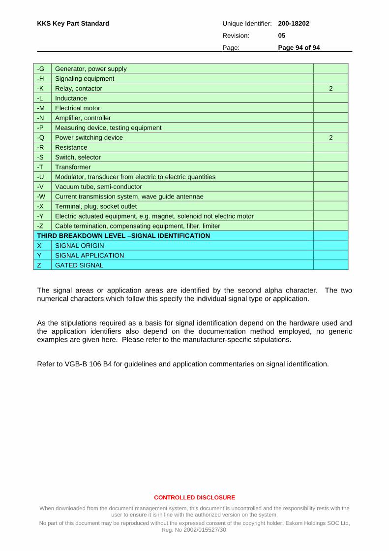
KKS Key Part Standard Unique Identifier: 200-18202
Revision: 05
Page: Page 94 of 94
CONTROLLED DISCLOSURE
When downloaded from the document management system, this document is uncontrolled and the responsibility rests with the user to ensure it is in line with the authorized version on the system.
No part of this document may be reproduced without the expressed consent of the copyright holder, Eskom Holdings SOC Ltd,
Reg. No 2002/015527/30.
-G Generator, power supply
-H Signaling equipment
-K Relay, contactor 2
-L Inductance
-M Electrical motor
-N Amplifier, controller
-P Measuring device, testing equipment
-Q Power switching device 2
-R Resistance
-S Switch, selector
-T Transformer
-U Modulator, transducer from electric to electric quantities
-V Vacuum tube, semi-conductor
-W Current transmission system, wave guide antennae
-X Terminal, plug, socket outlet
-Y Electric actuated equipment, e.g. magnet, solenoid not electric motor
-Z Cable termination, compensating equipment, filter, limiter
THIRD BREAKDOWN LEVEL –SIGNAL IDENTIFICATION
X SIGNAL ORIGIN
Y SIGNAL APPLICATION
Z GATED SIGNAL
The signal areas or application areas are identified by the second alpha character. The two numerical characters which follow this specify the individual signal type or application.
As the stipulations required as a basis for signal identification depend on the hardware used and the application identifiers also depend on the documentation method employed, no generic examples are given here. Please refer to the manufacturer-specific stipulations.
Refer to VGB-B 106 B4 for guidelines and application commentaries on signal identification.