pt. 1926, subpt. q, app. a 29 cfr ch. xvii (7–1–13 edition) pt. 1926, subpt. q, app. a 29 cfr...
TRANSCRIPT

404
29 CFR Ch. XVII (7–1–13 Edition) Pt. 1926, Subpt. Q, App. A
(5) The limited access zone shall re-main in place until the wall is ade-quately supported to prevent over-turning and to prevent collapse unless the height of wall is over eight feet, in which case, the limited access zone shall remain in place until the require-ments of paragraph (b) of this section have been met.
(b) All masonry walls over eight feet in height shall be adequately braced to prevent overturning and to prevent col-lapse unless the wall is adequately sup-ported so that it will not overturn or collapse. The bracing shall remain in place until permanent supporting ele-ments of the structure are in place.
APPENDIX A TO SUBPART Q OF PART 1926—REFERENCES TO SUBPART Q OF PART 1926
(This appendix is non-mandatory.)
The following non-mandatory references provide information which can be helpful in understanding and complying with the re-quirements contained in subpart Q.
• Accident Prevention Manual for Indus-trial Operations; Eighth Edition; National Safety Council.
• Building Code Requirements for Rein-forced Concrete (ACI 318–83).
• Formwork for Concrete (ACI SP–4). • Recommended Practice for Concrete
Formwork (ACI 347–78). • Safety Requirements for Concrete and
Masonry Work (ANSI A10.9–1983). • Standard Test Method for Compressive
Strength of Cylindrical Concrete Specimens (ASTM C39–86).
• Standard Test Method for Making and Curing Concrete Test Specimens in the Field (ASTM C31–85).
• Standard Test Method for Penetration Resistance of Hardened Concrete (ASTM C803–82).
• Standard Test Method for Compressive Strength of Concrete Cylinders Cast In-Place in Cylindrical Molds (ASTM C873–85).
• Standard Method for Developing Early Age Compressive Test Values and Projecting Later Age Strengths (ASTM C918–80).
• Recommended Practice for Inspection and Testing Agencies for Concrete, Steel and Bituminous Materials as Used in Construc-tion (ASTM E329–77).
• Method of Making and Curing Concrete Test Specimens in the Laboratory (ASTM C192–88).
• Methods of Obtaining and Testing Drilled Cores and Sawed Beams of Concrete (ASTM C42–87).
• Methods of Securing, Preparing and Test-ing Specimens from Hardened Lightweight
Insulating Concrete for Compressive Strength (ASTM C513–86).
• Test Method for Comprehensive Strength of Lightweight Insulating Concrete (ASTM C495–86).
• Method of Making, Accelerating Curing, and Testing of Concrete Compression Test Specimens (ASTM C684–81).
• Test Method for Compressive Strength of Concrete Using Portions of Beams Broken in Flexure (ASTM C116–68 (1980)).
Subpart R—Steel Erection
AUTHORITY: Section 3704 of the Contract Work Hours and Safety Standards Act (40 U.S.C. 3701); Sections 4, 6, and 8 of the Occu-pational Safety and Health Act of 1970 (29 U.S.C. 653, 655, 657); Secretary of Labor’s Order Nos. 3–2000 (65 FR 50017), 5–2002 (67 FR 65008), and 5–2007 (72 FR 31159); and 29 CFR part 1911.
SOURCE: 66 FR 5265, Jan. 18, 2001, unless otherwise noted.
§ 1926.750 Scope. (a) This subpart sets forth require-
ments to protect employees from the hazards associated with steel erection activities involved in the construction, alteration, and/or repair of single and multi-story buildings, bridges, and other structures where steel erection occurs. The requirements of this sub-part apply to employers engaged in steel erection unless otherwise speci-fied. This subpart does not cover elec-trical transmission towers, commu-nication and broadcast towers, or tanks.
NOTE TO PARAGRAPH (a): Examples of struc-tures where steel erection may occur include but are not limited to the following: Single and multi-story buildings; systems-engi-neered metal buildings; lift slab/tilt-up structures; energy exploration structures; energy production, transfer and storage structures and facilities; auditoriums; malls; amphitheaters; stadiums; power plants; mills; chemical process structures; bridges; trestles; overpasses; underpasses; viaducts; aqueducts; aerospace facilities and struc-tures; radar and communication structures; light towers; signage; billboards; score-boards; conveyor systems; conveyor supports and related framing; stairways; stair towers; fire escapes; draft curtains; fire containment structures; monorails; aerialways; catwalks; curtain walls; window walls; store fronts; el-evator fronts; entrances; skylights; metal roofs; industrial structures; hi-bay struc-tures; rail, marine and other transportation
VerDate Mar<15>2010 22:32 Aug 15, 2013 Jkt 229119 PO 00000 Frm 00414 Fmt 8010 Sfmt 8002 Q:\29\29V8.TXT ofr150 PsN: PC150

405
Occupational Safety and Health Admin., Labor § 1926.751
structures; sound barriers; water process and water containment structures; air and cable supported structures; space frames; geodesic domes; canopies; racks and rack support structures and frames; platforms; walkways; balconies; atriums; penthouses; car dumpers; stackers/reclaimers; cranes and craneways; bins; hoppers; ovens; furnaces; stacks; amusement park structures and rides; and artistic and monumental structures.
(b)(1) Steel erection activities in-clude hoisting, laying out, placing, connecting, welding, burning, guying, bracing, bolting, plumbing and rigging structural steel, steel joists and metal buildings; installing metal decking, curtain walls, window walls, siding sys-tems, miscellaneous metals, orna-mental iron and similar materials; and moving point-to-point while per-forming these activities.
(2) The following activities are cov-ered by this subpart when they occur during and are a part of steel erection activities: rigging, hoisting, laying out, placing, connecting, guying, bracing, dismantling, burning, welding, bolting, grinding, sealing, caulking, and all re-lated activities for construction, alter-ation and/or repair of materials and as-semblies such as structural steel; fer-rous metals and alloys; non-ferrous metals and alloys; glass; plastics and synthetic composite materials; struc-tural metal framing and related brac-ing and assemblies; anchoring devices; structural cabling; cable stays; perma-nent and temporary bents and towers; falsework for temporary supports of permanent steel members; stone and other non-precast concrete architec-tural materials mounted on steel frames; safety systems for steel erec-tion; steel and metal joists; metal decking and raceway systems and ac-cessories; metal roofing and acces-sories; metal siding; bridge flooring; cold formed steel framing; elevator beams; grillage; shelf racks; multi-pur-pose supports; crane rails and acces-sories; miscellaneous, architectural and ornamental metals and metal work; ladders; railings; handrails; fences and gates; gratings; trench cov-ers; floor plates; castings; sheet metal fabrications; metal panels and panel wall systems; louvers; column covers; enclosures and pockets; stairs; per-forated metals; ornamental iron work, expansion control including bridge ex-
pansion joint assemblies; slide bear-ings; hydraulic structures; fascias; sof-fit panels; penthouse enclosures; sky-lights; joint fillers; gaskets; sealants and seals; doors; windows; hardware; detention/security equipment and doors, windows and hardware; con-veying systems; building specialties; building equipment; machinery and plant equipment, furnishings and spe-cial construction.
(c) The duties of controlling contrac-tors under this subpart include, but are not limited to, the duties specified in §§ 1926.752 (a) and (c), 1926.755(b)(2), 1926.759(b), and 1926.760(e).
§ 1926.751 Definitions.
Anchored bridging means that the steel joist bridging is connected to a bridging terminus point.
Bolted diagonal bridging means diago-nal bridging that is bolted to a steel joist or joists.
Bridging clip means a device that is attached to the steel joist to allow the bolting of the bridging to the steel joist.
Bridging terminus point means a wall, a beam, tandem joists (with all bridg-ing installed and a horizontal truss in the plane of the top chord) or other ele-ment at an end or intermediate point(s) of a line of bridging that pro-vides an anchor point for the steel joist bridging.
Choker means a wire rope or syn-thetic fiber rigging assembly that is used to attach a load to a hoisting de-vice.
Cold forming means the process of using press brakes, rolls, or other methods to shape steel into desired cross sections at room temperature.
Column means a load-carrying vertical member that is part of the pri-mary skeletal framing system. Col-umns do not include posts.
Competent person (also defined in § 1926.32) means one who is capable of identifying existing and predictable hazards in the surroundings or working conditions which are unsanitary, haz-ardous, or dangerous to employees, and who has authorization to take prompt corrective measures to eliminate them.
Connector means an employee who, working with hoisting equipment, is
VerDate Mar<15>2010 22:32 Aug 15, 2013 Jkt 229119 PO 00000 Frm 00415 Fmt 8010 Sfmt 8002 Q:\29\29V8.TXT ofr150 PsN: PC150

406
29 CFR Ch. XVII (7–1–13 Edition) § 1926.751
placing and connecting structural members and/or components.
Constructibility means the ability to erect structural steel members in ac-cordance with subpart R without hav-ing to alter the over-all structural de-sign.
Construction load (for joist erection) means any load other than the weight of the employee(s), the joists and the bridging bundle.
Controlled Decking Zone (CDZ) means an area in which certain work (for ex-ample, initial installation and place-ment of metal decking) may take place without the use of guardrail systems, personal fall arrest systems, fall re-straint systems, or safety net systems and where access to the zone is con-trolled.
Controlled load lowering means low-ering a load by means of a mechanical hoist drum device that allows a hoisted load to be lowered with maximum con-trol using the gear train or hydraulic components of the hoist mechanism. Controlled load lowering requires the use of the hoist drive motor, rather than the load hoist brake, to lower the load.
Controlling contractor means a prime contractor, general contractor, con-struction manager or any other legal entity which has the overall responsi-bility for the construction of the project—its planning, quality and com-pletion.
Critical lift means a lift that (1) ex-ceeds 75 percent of the rated capacity of the crane or derrick, or (2) requires the use of more than one crane or der-rick.
Decking hole means a gap or void more than 2 inches (5.1 cm) in its least dimension and less than 12 inches (30.5 cm) in its greatest dimension in a floor, roof or other walking/working surface. Pre-engineered holes in cel-lular decking (for wires, cables, etc.) are not included in this definition.
Derrick floor means an elevated floor of a building or structure that has been designated to receive hoisted pieces of steel prior to final placement.
Double connection means an attach-ment method where the connection point is intended for two pieces of steel which share common bolts on either side of a central piece.
Double connection seat means a struc-tural attachment that, during the in-stallation of a double connection, sup-ports the first member while the sec-ond member is connected.
Erection bridging means the bolted di-agonal bridging that is required to be installed prior to releasing the hoisting cables from the steel joists.
Fall restraint system means a fall pro-tection system that prevents the user from falling any distance. The system is comprised of either a body belt or body harness, along with an anchorage, connectors and other necessary equip-ment. The other components typically include a lanyard, and may also in-clude a lifeline and other devices.
Final interior perimeter means the pe-rimeter of a large permanent open space within a building such as an atri-um or courtyard. This does not include openings for stairways, elevator shafts, etc.
Girt (in systems-engineered metal build-ings) means a ‘‘Z’’ or ‘‘C’’ shaped mem-ber formed from sheet steel spanning between primary framing and sup-porting wall material.
Headache ball means a weighted hook that is used to attach loads to the hoist load line of the crane.
Hoisting equipment means commer-cially manufactured lifting equipment designed to lift and position a load of known weight to a location at some known elevation and horizontal dis-tance from the equipment’s center of rotation. ‘‘Hoisting equipment’’ in-cludes but is not limited to cranes, der-ricks, tower cranes, barge-mounted derricks or cranes, gin poles and gan-try hoist systems. A ‘‘come-a-long’’ (a mechanical device, usually consisting of a chain or cable attached at each end, that is used to facilitate move-ment of materials through leverage) is not considered ‘‘hoisting equipment.’’
Leading edge means the unprotected side and edge of a floor, roof, or formwork for a floor or other walking/ working surface (such as deck) which changes location as additional floor, roof, decking or formwork sections are placed, formed or constructed.
Metal decking means a commercially manufactured, structural grade, cold rolled metal panel formed into a series of parallel ribs; for this subpart, this
VerDate Mar<15>2010 22:32 Aug 15, 2013 Jkt 229119 PO 00000 Frm 00416 Fmt 8010 Sfmt 8002 Q:\29\29V8.TXT ofr150 PsN: PC150

407
Occupational Safety and Health Admin., Labor § 1926.751
includes metal floor and roof decks, standing seam metal roofs, other metal roof systems and other products such as bar gratings, checker plate, ex-panded metal panels, and similar prod-ucts. After installation and proper fas-tening, these decking materials serve a combination of functions including, but not limited to: a structural ele-ment designed in combination with the structure to resist, distribute and transfer loads, stiffen the structure and provide a diaphragm action; a walking/ working surface; a form for concrete slabs; a support for roofing systems; and a finished floor or roof.
Multiple lift rigging means a rigging assembly manufactured by wire rope rigging suppliers that facilitates the attachment of up to five independent loads to the hoist rigging of a crane.
Opening means a gap or void 12 inches (30.5 cm) or more in its least di-mension in a floor, roof or other walk-ing/working surface. For the purposes of this subpart, skylights and smoke domes that do not meet the strength requirements of § 1926.754(e)(3) shall be regarded as openings.
Permanent floor means a structurally completed floor at any level or ele-vation (including slab on grade).
Personal fall arrest system means a system used to arrest an employee in a fall from a working level. A personal fall arrest system consists of an an-chorage, connectors, a body harness and may include a lanyard, decelera-tion device, lifeline, or suitable com-bination of these. The use of a body belt for fall arrest is prohibited.
Positioning device system means a body belt or body harness rigged to allow an employee to be supported on an ele-vated, vertical surface, such as a wall or column and work with both hands free while leaning.
Post means a structural member with a longitudinal axis that is essentially vertical, that: (1) weighs 300 pounds or less and is axially loaded (a load press-es down on the top end), or (2) is not axially loaded, but is laterally re-strained by the above member. Posts typically support stair landings, wall framing, mezzanines and other sub-structures.
Project structural engineer of record means the registered, licensed profes-
sional responsible for the design of structural steel framing and whose seal appears on the structural contract doc-uments.
Purlin (in systems-engineered metal buildings) means a ‘‘Z’’ or ‘‘C’’ shaped member formed from sheet steel span-ning between primary framing and sup-porting roof material.
Qualified person (also defined in § 1926.32) means one who, by possession of a recognized degree, certificate, or professional standing, or who by exten-sive knowledge, training, and experi-ence, has successfully demonstrated the ability to solve or resolve problems relating to the subject matter, the work, or the project.
Safety deck attachment means an ini-tial attachment that is used to secure an initially placed sheet of decking to keep proper alignment and bearing with structural support members.
Shear connector means headed steel studs, steel bars, steel lugs, and similar devices which are attached to a struc-tural member for the purpose of achieving composite action with con-crete.
Steel erection means the construction, alteration or repair of steel buildings, bridges and other structures, including the installation of metal decking and all planking used during the process of erection.
Steel joist means an open web, sec-ondary load-carrying member of 144 feet (43.9 m) or less, designed by the manufacturer, used for the support of floors and roofs. This does not include structural steel trusses or cold-formed joists.
Steel joist girder means an open web, primary load-carrying member, de-signed by the manufacturer, used for the support of floors and roofs. This does not include structural steel truss-es.
Steel truss means an open web mem-ber designed of structural steel compo-nents by the project structural engi-neer of record. For the purposes of this subpart, a steel truss is considered equivalent to a solid web structural member.
VerDate Mar<15>2010 22:32 Aug 15, 2013 Jkt 229119 PO 00000 Frm 00417 Fmt 8010 Sfmt 8002 Q:\29\29V8.TXT ofr150 PsN: PC150

408
29 CFR Ch. XVII (7–1–13 Edition) § 1926.752
Structural steel means a steel member, or a member made of a substitute ma-terial (such as, but not limited to, fi-berglass, aluminum or composite mem-bers). These members include, but are not limited to, steel joists, joist gird-ers, purlins, columns, beams, trusses, splices, seats, metal decking, girts, and all bridging, and cold formed metal framing which is integrated with the structural steel framing of a building.
Systems-engineered metal building means a metal, field-assembled build-ing system consisting of framing, roof and wall coverings. Typically, many of these components are cold-formed shapes. These individual parts are fab-ricated in one or more manufacturing facilities and shipped to the job site for assembly into the final structure. The engineering design of the system is normally the responsibility of the sys-tems-engineered metal building manu-facturer.
Tank means a container for holding gases, liquids or solids.
Unprotected sides and edges means any side or edge (except at entrances to points of access) of a walking/working surface, for example a, floor, roof, ramp or runway, where there is no wall or guardrail system at least 39 inches (1.0 m) high.
§ 1926.752 Site layout, site-specific erection plan and construction se-quence.
(a) Approval to begin steel erection. Be-fore authorizing the commencement of steel erection, the controlling con-tractor shall ensure that the steel erec-tor is provided with the following writ-ten notifications:
(1) The concrete in the footings, piers and walls and the mortar in the ma-sonry piers and walls has attained, on the basis of an appropriate ASTM standard test method of field-cured samples, either 75 percent of the in-tended minimum compressive design strength or sufficient strength to sup-port the loads imposed during steel erection.
(2) Any repairs, replacements and modifications to the anchor bolts were conducted in accordance with § 1926.755(b).
(b) Commencement of steel erection. A steel erection contractor shall not
erect steel unless it has received writ-ten notification that the concrete in the footings, piers and walls or the mortar in the masonry piers and walls has attained, on the basis of an appro-priate ASTM standard test method of field-cured samples, either 75 percent of the intended minimum compressive design strength or sufficient strength to support the loads imposed during steel erection.
(c) Site layout. The controlling con-tractor shall ensure that the following is provided and maintained:
(1) Adequate access roads into and through the site for the safe delivery and movement of derricks, cranes, trucks, other necessary equipment, and the material to be erected and means and methods for pedestrian and vehic-ular control. Exception: this require-ment does not apply to roads outside of the construction site.
(2) A firm, properly graded, drained area, readily accessible to the work with adequate space for the safe stor-age of materials and the safe operation of the erector’s equipment.
(d) Pre-planning of overhead hoisting operations. All hoisting operations in steel erection shall be pre-planned to ensure that the requirements of § 1926.753(d) are met.
(e) Site-specific erection plan. Where employers elect, due to conditions spe-cific to the site, to develop alternate means and methods that provide em-ployee protection in accordance with § 1926.753(c)(5), § 1926.757(a)(4) or § 1926.757(e)(4), a site-specific erection plan shall be developed by a qualified person and be available at the work site. Guidelines for establishing a site- specific erection plan are contained in appendix A to this subpart.
§ 1926.753 Hoisting and rigging.
(a) All the provisions of subpart CC apply to hoisting and rigging with the exception of § 1926.1431(a).
(b) In addition, paragraphs (c) through (e) of this section apply re-garding the hazards associated with hoisting and rigging.
(c) General. (1) Pre-shift visual in-spection of cranes.
(i) Cranes being used in steel erection activities shall be visually inspected
VerDate Mar<15>2010 22:32 Aug 15, 2013 Jkt 229119 PO 00000 Frm 00418 Fmt 8010 Sfmt 8002 Q:\29\29V8.TXT ofr150 PsN: PC150

409
Occupational Safety and Health Admin., Labor § 1926.753
prior to each shift by a competent per-son; the inspection shall include obser-vation for deficiencies during oper-ation. At a minimum this inspection shall include the following:
(A) All control mechanisms for mal-adjustments;
(B) Control and drive mechanism for excessive wear of components and con-tamination by lubricants, water or other foreign matter;
(C) Safety devices, including but not limited to boom angle indicators, boom stops, boom kick out devices, anti-two block devices, and load moment indica-tors where required;
(D) Air, hydraulic, and other pressur-ized lines for deterioration or leakage, particularly those which flex in normal operation;
(E) Hooks and latches for deforma-tion, chemical damage, cracks, or wear;
(F) Wire rope reeving for compliance with hoisting equipment manufactur-er’s specifications;
(G) Electrical apparatus for malfunc-tioning, signs of excessive deteriora-tion, dirt, or moisture accumulation;
(H) Hydraulic system for proper fluid level;
(I) Tires for proper inflation and con-dition;
(J) Ground conditions around the hoisting equipment for proper support, including ground settling under and around outriggers, ground water accu-mulation, or similar conditions;
(K) The hoisting equipment for level position; and
(L) The hoisting equipment for level position after each move and setup.
(ii) If any deficiency is identified, an immediate determination shall be made by the competent person as to whether the deficiency constitutes a hazard.
(iii) If the deficiency is determined to constitute a hazard, the hoisting equip-ment shall be removed from service until the deficiency has been corrected.
(iv) The operator shall be responsible for those operations under the opera-tor’s direct control. Whenever there is any doubt as to safety, the operator shall have the authority to stop and refuse to handle loads until safety has been assured.
(2) A qualified rigger (a rigger who is also a qualified person) shall inspect the rigging prior to each shift in ac-cordance with § 1926.251.
(3) The headache ball, hook or load shall not be used to transport per-sonnel except as provided in paragraph (c)(4) of this section.
(4) Cranes or derricks may be used to hoist employees on a personnel plat-form when work under this subpart is being conducted, provided that all pro-visions of § 1926.1431 (except for § 1926.1431(a)) are met.
(5) Safety latches on hooks shall not be deactivated or made inoperable ex-cept:
(i) When a qualified rigger has deter-mined that the hoisting and placing of purlins and single joists can be per-formed more safely by doing so; or
(ii) When equivalent protection is provided in a site-specific erection plan.
(d) Working under loads. (1) Routes for suspended loads shall be pre-planned to ensure that no employee is required to work directly below a suspended load except for:
(i) Employees engaged in the initial connection of the steel; or
(ii) Employees necessary for the hooking or unhooking of the load.
(2) When working under suspended loads, the following criteria shall be met:
(i) Materials being hoisted shall be rigged to prevent unintentional dis-placement;
(ii) Hooks with self-closing safety latches or their equivalent shall be used to prevent components from slip-ping out of the hook; and
(iii) All loads shall be rigged by a qualified rigger
(e) Multiple lift rigging procedure. (1) A multiple lift shall only be performed if the following criteria are met:
(i) A multiple lift rigging assembly is used;
(ii) A maximum of five members are hoisted per lift;
(iii) Only beams and similar struc-tural members are lifted; and
(iv) All employees engaged in the multiple lift have been trained in these procedures in accordance with § 1926.761(c)(1).
VerDate Mar<15>2010 22:32 Aug 15, 2013 Jkt 229119 PO 00000 Frm 00419 Fmt 8010 Sfmt 8002 Q:\29\29V8.TXT ofr150 PsN: PC150

410
29 CFR Ch. XVII (7–1–13 Edition) § 1926.754
(v) No crane is permitted to be used for a multiple lift where such use is contrary to the manufacturer’s speci-fications and limitations.
(2) Components of the multiple lift rigging assembly shall be specifically designed and assembled with a max-imum capacity for total assembly and for each individual attachment point. This capacity, certified by the manu-facturer or a qualified rigger, shall be based on the manufacturer’s specifica-tions with a 5 to 1 safety factor for all components.
(3) The total load shall not exceed: (i) The rated capacity of the hoisting
equipment specified in the hoisting equipment load charts;
(ii) The rigging capacity specified in the rigging rating chart.
(4) The multiple lift rigging assembly shall be rigged with members:
(i) Attached at their center of grav-ity and maintained reasonably level;
(ii) Rigged from top down; and (iii) Rigged at least 7 feet (2.1 m)
apart. (5) The members on the multiple lift
rigging assembly shall be set from the bottom up.
(6) Controlled load lowering shall be used whenever the load is over the con-nectors.
[66 FR 5265, Jan. 18, 2001, as amended at 75 FR 48134, Aug. 9, 2010]
§ 1926.754 Structural steel assembly. (a) Structural stability shall be
maintained at all times during the erection process.
NOTE TO PARAGRAPH (a): Federal Highway Administration (FHWA) regulations incor-porate by reference a number of standards, policies, and standard specifications pub-lished by the American Association of State Highway and Transportation Officials (AASHTO) and other organizations. (See 23 CFR 625.4). Many of these incorporated pro-visions may be relevant to maintaining structural stability during the erection proc-ess. For instance, as of May 17, 2010, in many cases FHWA requires a Registered Engineer to prepare and seal working drawings for falsework used in highway bridge construc-tion. (See AASHTO Specifications for High-way Bridges, Div. II, § 3.2.1, 15th edition, 1992, which FHWA incorporates by reference in 23 CFR 625.4). FHWA also encourages compli-ance with AASHTO Specifications that the FHWA regulations do not currently incor-
porate by reference. (See http:// www.fhwa.dot.gov/bridge/lrfd/index.htm.)
(b) The following additional require-ments shall apply for multi-story structures:
(1) The permanent floors shall be in-stalled as the erection of structural members progresses, and there shall be not more than eight stories between the erection floor and the upper-most permanent floor, except where the structural integrity is maintained as a result of the design.
(2) At no time shall there be more than four floors or 48 feet (14.6 m), whichever is less, of unfinished bolting or welding above the foundation or up-permost permanently secured floor, ex-cept where the structural integrity is maintained as a result of the design.
(3) A fully planked or decked floor or nets shall be maintained within two stories or 30 feet (9.1 m), whichever is less, directly under any erection work being performed.
(c) Walking/working surfaces—shear connectors and other similar devices—(1) Tripping hazards. Shear connectors (such as headed steel studs, steel bars or steel lugs), reinforcing bars, de-formed anchors or threaded studs shall not be attached to the top flanges of beams, joists or beam attachments so that they project vertically from or horizontally across the top flange of the member until after the metal deck-ing, or other walking/working surface, has been installed.
(2) Installation of shear connectors on composite floors, roofs and bridge decks. When shear connectors are used in con-struction of composite floors, roofs and bridge decks, employees shall lay out and install the shear connectors after the metal decking has been installed, using the metal decking as a working platform. Shear connectors shall not be installed from within a controlled decking zone (CDZ), as specified in § 1926.760(c)(8).
(d) Plumbing-up. (1) When deemed necessary by a competent person, plumbing-up equipment shall be in-stalled in conjunction with the steel erection process to ensure the stability of the structure.
(2) When used, plumbing-up equip-ment shall be in place and properly in-stalled before the structure is loaded
VerDate Mar<15>2010 22:32 Aug 15, 2013 Jkt 229119 PO 00000 Frm 00420 Fmt 8010 Sfmt 8002 Q:\29\29V8.TXT ofr150 PsN: PC150

411
Occupational Safety and Health Admin., Labor § 1926.755
with construction material such as loads of joists, bundles of decking or bundles of bridging.
(3) Plumbing-up equipment shall be removed only with the approval of a competent person.
(e) Metal decking—(1) Hoisting, landing and placing of metal decking bundles. (i) Bundle packaging and strapping shall not be used for hoisting unless specifi-cally designed for that purpose.
(ii) If loose items such as dunnage, flashing, or other materials are placed on the top of metal decking bundles to be hoisted, such items shall be secured to the bundles.
(iii) Bundles of metal decking on joists shall be landed in accordance with § 1926.757(e)(4).
(iv) Metal decking bundles shall be landed on framing members so that enough support is provided to allow the bundles to be unbanded without dis-lodging the bundles from the supports.
(v) At the end of the shift or when en-vironmental or jobsite conditions re-quire, metal decking shall be secured against displacement.
(2) Roof and floor holes and openings. Metal decking at roof and floor holes and openings shall be installed as fol-lows:
(i) Framed metal deck openings shall have structural members turned down to allow continuous deck installation except where not allowed by structural design constraints or constructibility.
(ii) Roof and floor holes and openings shall be decked over. Where large size, configuration or other structural de-sign does not allow openings to be decked over (such as elevator shafts, stair wells, etc.) employees shall be protected in accordance with § 1926.760(a)(1).
(iii) Metal decking holes and open-ings shall not be cut until immediately prior to being permanently filled with the equipment or structure needed or intended to fulfill its specific use and which meets the strength requirements of paragraph (e)(3) of this section, or shall be immediately covered.
(3) Covering roof and floor openings. (i) Covers for roof and floor openings shall be capable of supporting, without fail-ure, twice the weight of the employees, equipment and materials that may be imposed on the cover at any one time.
(ii) All covers shall be secured when installed to prevent accidental dis-placement by the wind, equipment or employees.
(iii) All covers shall be painted with high-visibility paint or shall be marked with the word ‘‘HOLE’’ or ‘‘COVER’’ to provide warning of the hazard.
(iv) Smoke dome or skylight fixtures that have been installed, are not con-sidered covers for the purpose of this section unless they meet the strength requirements of paragraph (e)(3)(i) of this section.
(4) Decking gaps around columns. Wire mesh, exterior plywood, or equivalent, shall be installed around columns where planks or metal decking do not fit tightly. The materials used must be of sufficient strength to provide fall protection for personnel and prevent objects from falling through.
(5) Installation of metal decking. (i) Ex-cept as provided in § 1926.760(c), metal decking shall be laid tightly and imme-diately secured upon placement to pre-vent accidental movement or displace-ment.
(ii) During initial placement, metal decking panels shall be placed to en-sure full support by structural mem-bers.
(6) Derrick floors. (i) A derrick floor shall be fully decked and/or planked and the steel member connections com-pleted to support the intended floor loading.
(ii) Temporary loads placed on a der-rick floor shall be distributed over the underlying support members so as to prevent local overloading of the deck material.
[66 FR 5265, Jan. 18, 2001, as amended at 71 FR 2885, Jan. 18, 2006; 71 FR 16674, Apr. 3, 2006; 75 FR 27429, May 17, 2010]
§ 1926.755 Column anchorage.
(a) General requirements for erection stability. (1) All columns shall be an-chored by a minimum of 4 anchor rods (anchor bolts).
(2) Each column anchor rod (anchor bolt) assembly, including the column- to-base plate weld and the column foundation, shall be designed to resist a minimum eccentric gravity load of 300 pounds (136.2 kg) located 18 inches (.46m) from the extreme outer face of
VerDate Mar<15>2010 22:32 Aug 15, 2013 Jkt 229119 PO 00000 Frm 00421 Fmt 8010 Sfmt 8002 Q:\29\29V8.TXT ofr150 PsN: PC150

412
29 CFR Ch. XVII (7–1–13 Edition) § 1926.756
the column in each direction at the top of the column shaft.
(3) Columns shall be set on level fin-ished floors, pre-grouted leveling plates, leveling nuts, or shim packs which are adequate to transfer the con-struction loads.
(4) All columns shall be evaluated by a competent person to determine whether guying or bracing is needed; if guying or bracing is needed, it shall be installed.
(b) Repair, replacement or field modi-fication of anchor rods (anchor bolts). (1) Anchor rods (anchor bolts) shall not be repaired, replaced or field-modified without the approval of the project structural engineer of record.
(2) Prior to the erection of a column, the controlling contractor shall pro-vide written notification to the steel erector if there has been any repair, re-placement or modification of the an-chor rods (anchor bolts) of that col-umn.
§ 1926.756 Beams and columns. (a) General. (1) During the final plac-
ing of solid web structural members, the load shall not be released from the hoisting line until the members are se-cured with at least two bolts per con-nection, of the same size and strength as shown in the erection drawings, drawn up wrench-tight or the equiva-lent as specified by the project struc-tural engineer of record, except as specified in paragraph (b) of this sec-tion.
(2) A competent person shall deter-mine if more than two bolts are nec-essary to ensure the stability of canti-levered members; if additional bolts are needed, they shall be installed.
(b) Diagonal bracing. Solid web struc-tural members used as diagonal brac-ing shall be secured by at least one bolt per connection drawn up wrench-tight or the equivalent as specified by the project structural engineer of record.
(c) (1) Double connections at columns and/or at beam webs over a column. When two structural members on opposite sides of a column web, or a beam web over a column, are connected sharing common connection holes, at least one bolt with its wrench-tight nut shall re-main connected to the first member unless a shop-attached or field-at-
tached seat or equivalent connection device is supplied with the member to secure the first member and prevent the column from being displaced (See appendix H to this subpart for exam-ples of equivalent connection devices).
(2) If a seat or equivalent device is used, the seat (or device) shall be de-signed to support the load during the double connection process. It shall be adequately bolted or welded to both a supporting member and the first mem-ber before the nuts on the shared bolts are removed to make the double con-nection.
(d) Column splices. Each column splice shall be designed to resist a minimum eccentric gravity load of 300 pounds (136.2 kg) located 18 inches (.46 m) from the extreme outer face of the column in each direction at the top of the col-umn shaft.
(e) Perimeter columns. Perimeter col-umns shall not be erected unless:
(1) The perimeter columns extend a minimum of 48 inches (1.2 m) above the finished floor to permit installation of perimeter safety cables prior to erec-tion of the next tier, except where constructibility does not allow (see ap-pendix F to this subpart);
(2) The perimeter columns have holes or other devices in or attached to pe-rimeter columns at 42–45 inches (107–114 cm) above the finished floor and the midpoint between the finished floor and the top cable to permit installa-tion of perimeter safety cables required by § 1926.760(a)(2), except where constructibility does not allow. (See appendix F to this subpart).
§ 1926.757 Open web steel joists. (a) General. (1) Except as provided in
paragraph (a)(2) of this section, where steel joists are used and columns are not framed in at least two directions with solid web structural steel mem-bers, a steel joist shall be field-bolted at the column to provide lateral sta-bility to the column during erection. For the installation of this joist:
(i) A vertical stabilizer plate shall be provided on each column for steel joists. The plate shall be a minimum of 6 inch by 6 inch (152 mm by 152 mm) and shall extend at least 3 inches (76 mm) below the bottom chord of the joist with a 13⁄16 inch (21 mm) hole to
VerDate Mar<15>2010 22:32 Aug 15, 2013 Jkt 229119 PO 00000 Frm 00422 Fmt 8010 Sfmt 8002 Q:\29\29V8.TXT ofr150 PsN: PC150

413
Occupational Safety and Health Admin., Labor § 1926.757
provide an attachment point for guying or plumbing cables.
(ii) The bottom chords of steel joists at columns shall be stabilized to pre-vent rotation during erection.
(iii) Hoisting cables shall not be re-leased until the seat at each end of the steel joist is field-bolted, and each end of the bottom chord is restrained by the column stabilizer plate.
(2) Where constructibility does not allow a steel joist to be installed at the column:
(i) an alternate means of stabilizing joists shall be installed on both sides near the column and shall:
(A) provide stability equivalent to paragraph (a)(1) of this section;
(B) be designed by a qualified person; (C) be shop installed; and (D) be included in the erection draw-
ings. (ii) hoisting cables shall not be re-
leased until the seat at each end of the steel joist is field-bolted and the joist is stabilized.
(3) Where steel joists at or near col-umns span 60 feet (18.3 m) or less, the joist shall be designed with sufficient strength to allow one employee to re-lease the hoisting cable without the need for erection bridging.
(4) Where steel joists at or near col-umns span more than 60 feet (18.3 m), the joists shall be set in tandem with all bridging installed unless an alter-native method of erection, which pro-vides equivalent stability to the steel joist, is designed by a qualified person and is included in the site-specific erec-tion plan.
(5) A steel joist or steel joist girder shall not be placed on any support structure unless such structure is sta-bilized.
(6) When steel joist(s) are landed on a structure, they shall be secured to pre-vent unintentional displacement prior to installation.
(7) No modification that affects the strength of a steel joist or steel joist girder shall be made without the ap-proval of the project structural engi-neer of record.
(8) Field-bolted joists. (i) Except for steel joists that have been pre-assem-bled into panels, connections of indi-vidual steel joists to steel structures in bays of 40 feet (12.2 m) or more shall be
fabricated to allow for field bolting during erection.
(ii) These connections shall be field- bolted unless constructibility does not allow.
(9) Steel joists and steel joist girders shall not be used as anchorage points for a fall arrest system unless written approval to do so is obtained from a qualified person.
(10) A bridging terminus point shall be established before bridging is in-stalled. (See appendix C to this sub-part.)
(b) Attachment of steel joists and steel joist girders. (1) Each end of ‘‘K’’ series steel joists shall be attached to the support structure with a minimum of two 1⁄8-inch (3 mm) fillet welds 1 inch (25 mm) long or with two 1⁄2-inch (13 mm) bolts, or the equivalent.
(2) Each end of ‘‘LH’’ and ‘‘DLH’’ se-ries steel joists and steel joist girders shall be attached to the support struc-ture with a minimum of two 1⁄4-inch (6 mm) fillet welds 2 inches (51 mm) long, or with two 3⁄4-inch (19 mm) bolts, or the equivalent.
(3) Except as provided in paragraph (b)(4) of this section, each steel joist shall be attached to the support struc-ture, at least at one end on both sides of the seat, immediately upon place-ment in the final erection position and before additional joists are placed.
(4) Panels that have been pre-assem-bled from steel joists with bridging shall be attached to the structure at each corner before the hoisting cables are released.
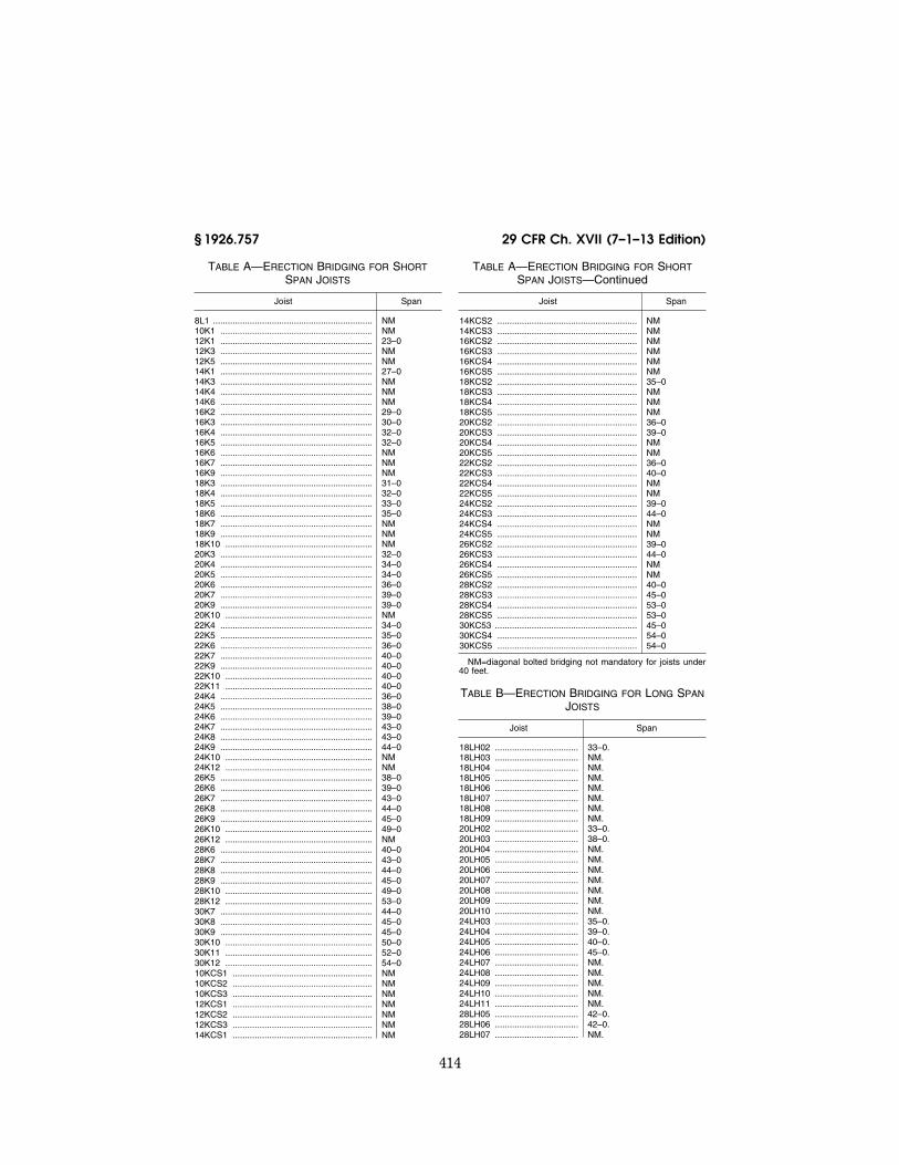
(c) Erection of steel joists. (1) Both sides of the seat of one end of each steel joist that requires bridging under Tables A and B shall be attached to the support structure before hoisting ca-bles are released.
(2) For joists over 60 feet, both ends of the joist shall be attached as speci-fied in paragraph (b) of this section and the provisions of paragraph (d) of this section met before the hoisting cables are released.
(3) On steel joists that do not require erection bridging under Tables A and B, only one employee shall be allowed on the joist until all bridging is in-stalled and anchored.
VerDate Mar<15>2010 22:32 Aug 15, 2013 Jkt 229119 PO 00000 Frm 00423 Fmt 8010 Sfmt 8002 Q:\29\29V8.TXT ofr150 PsN: PC150
414
29 CFR Ch. XVII (7–1–13 Edition) § 1926.757
TABLE A—ERECTION BRIDGING FOR SHORT SPAN JOISTS
Joist Span
8L1 ................................................................. NM 10K1 .............................................................. NM 12K1 .............................................................. 23–0 12K3 .............................................................. NM 12K5 .............................................................. NM 14K1 .............................................................. 27–0 14K3 .............................................................. NM 14K4 .............................................................. NM 14K6 .............................................................. NM 16K2 .............................................................. 29–0 16K3 .............................................................. 30–0 16K4 .............................................................. 32–0 16K5 .............................................................. 32–0 16K6 .............................................................. NM 16K7 .............................................................. NM 16K9 .............................................................. NM 18K3 .............................................................. 31–0 18K4 .............................................................. 32–0 18K5 .............................................................. 33–0 18K6 .............................................................. 35–0 18K7 .............................................................. NM 18K9 .............................................................. NM 18K10 ............................................................ NM 20K3 .............................................................. 32–0 20K4 .............................................................. 34–0 20K5 .............................................................. 34–0 20K6 .............................................................. 36–0 20K7 .............................................................. 39–0 20K9 .............................................................. 39–0 20K10 ............................................................ NM 22K4 .............................................................. 34–0 22K5 .............................................................. 35–0 22K6 .............................................................. 36–0 22K7 .............................................................. 40–0 22K9 .............................................................. 40–0 22K10 ............................................................ 40–0 22K11 ............................................................ 40–0 24K4 .............................................................. 36–0 24K5 .............................................................. 38–0 24K6 .............................................................. 39–0 24K7 .............................................................. 43–0 24K8 .............................................................. 43–0 24K9 .............................................................. 44–0 24K10 ............................................................ NM 24K12 ............................................................ NM 26K5 .............................................................. 38–0 26K6 .............................................................. 39–0 26K7 .............................................................. 43–0 26K8 .............................................................. 44–0 26K9 .............................................................. 45–0 26K10 ............................................................ 49–0 26K12 ............................................................ NM 28K6 .............................................................. 40–0 28K7 .............................................................. 43–0 28K8 .............................................................. 44–0 28K9 .............................................................. 45–0 28K10 ............................................................ 49–0 28K12 ............................................................ 53–0 30K7 .............................................................. 44–0 30K8 .............................................................. 45–0 30K9 .............................................................. 45–0 30K10 ............................................................ 50–0 30K11 ............................................................ 52–0 30K12 ............................................................ 54–0 10KCS1 ......................................................... NM 10KCS2 ......................................................... NM 10KCS3 ......................................................... NM 12KCS1 ......................................................... NM 12KCS2 ......................................................... NM 12KCS3 ......................................................... NM 14KCS1 ......................................................... NM
TABLE A—ERECTION BRIDGING FOR SHORT SPAN JOISTS—Continued
Joist Span
14KCS2 ......................................................... NM 14KCS3 ......................................................... NM 16KCS2 ......................................................... NM 16KCS3 ......................................................... NM 16KCS4 ......................................................... NM 16KCS5 ......................................................... NM 18KCS2 ......................................................... 35–0 18KCS3 ......................................................... NM 18KCS4 ......................................................... NM 18KCS5 ......................................................... NM 20KCS2 ......................................................... 36–0 20KCS3 ......................................................... 39–0 20KCS4 ......................................................... NM 20KCS5 ......................................................... NM 22KCS2 ......................................................... 36–0 22KCS3 ......................................................... 40–0 22KCS4 ......................................................... NM 22KCS5 ......................................................... NM 24KCS2 ......................................................... 39–0 24KCS3 ......................................................... 44–0 24KCS4 ......................................................... NM 24KCS5 ......................................................... NM 26KCS2 ......................................................... 39–0 26KCS3 ......................................................... 44–0 26KCS4 ......................................................... NM 26KCS5 ......................................................... NM 28KCS2 ......................................................... 40–0 28KCS3 ......................................................... 45–0 28KCS4 ......................................................... 53–0 28KCS5 ......................................................... 53–0 30KC53 .......................................................... 45–0 30KCS4 ......................................................... 54–0 30KCS5 ......................................................... 54–0
NM=diagonal bolted bridging not mandatory for joists under 40 feet.
TABLE B—ERECTION BRIDGING FOR LONG SPAN JOISTS
Joist Span
18LH02 .................................. 33–0. 18LH03 .................................. NM. 18LH04 .................................. NM. 18LH05 .................................. NM. 18LH06 .................................. NM. 18LH07 .................................. NM. 18LH08 .................................. NM. 18LH09 .................................. NM. 20LH02 .................................. 33–0. 20LH03 .................................. 38–0. 20LH04 .................................. NM. 20LH05 .................................. NM. 20LH06 .................................. NM. 20LH07 .................................. NM. 20LH08 .................................. NM. 20LH09 .................................. NM. 20LH10 .................................. NM. 24LH03 .................................. 35–0. 24LH04 .................................. 39–0. 24LH05 .................................. 40–0. 24LH06 .................................. 45–0. 24LH07 .................................. NM. 24LH08 .................................. NM. 24LH09 .................................. NM. 24LH10 .................................. NM. 24LH11 .................................. NM. 28LH05 .................................. 42–0. 28LH06 .................................. 42–0. 28LH07 .................................. NM.
VerDate Mar<15>2010 22:32 Aug 15, 2013 Jkt 229119 PO 00000 Frm 00424 Fmt 8010 Sfmt 8002 Q:\29\29V8.TXT ofr150 PsN: PC150

415
Occupational Safety and Health Admin., Labor § 1926.757
TABLE B—ERECTION BRIDGING FOR LONG SPAN JOISTS—Continued
Joist Span
28LH08 .................................. NM. 28LH09 .................................. NM. 28LH10 .................................. NM. 28LH11 .................................. NM. 28LH12 .................................. NM. 28LH13 .................................. NM. 32LH06 .................................. 47–0 through 60–0. 32LH07 .................................. 47–0 through 60–0. 32LH08 .................................. 55–0 through 60–0. 32LH09 .................................. NM through 60–0. 32LH10 .................................. NM through 60–0. 32LH11 .................................. NM through 60–0. 32LH12 .................................. NM through 60–0. 32LH13 .................................. NM through 60–0. 32LH14 .................................. NM through 60–0. 32LH15 .................................. NM through 60–0. 36LH07 .................................. 47–0 through 60–0. 36LH08 .................................. 47–0 through 60–0. 36LH09 .................................. 57–0 through 60–0. 36LH10 .................................. NM through 60–0. 36LH11 .................................. NM through 60–0. 36LH12 .................................. NM through 60–0. 36LH13 .................................. NM through 60–0. 36LH14 .................................. NM through 60–0. 36LH15 .................................. NM through 60–0.
NM = diagonal bolted bridging not mandatory for joists under 40 feet.
(4) Employees shall not be allowed on steel joists where the span of the steel joist is equal to or greater than the span shown in Tables A and B except in accordance with § 1926.757(d).
(5) When permanent bridging ter-minus points cannot be used during erection, additional temporary bridg-ing terminus points are required to provide stability. (See appendix C of this subpart.)
(d) Erection bridging. (1) Where the span of the steel joist is equal to or greater than the span shown in Tables A and B, the following shall apply:
(i) A row of bolted diagonal erection bridging shall be installed near the midspan of the steel joist;
(ii) Hoisting cables shall not be re-leased until this bolted diagonal erec-tion bridging is installed and anchored; and
(iii) No more than one employee shall be allowed on these spans until all other bridging is installed and an-chored.
(2) Where the span of the steel joist is over 60 feet (18.3 m) through 100 feet (30.5 m), the following shall apply:
(i) All rows of bridging shall be bolted diagonal bridging;
(ii) Two rows of bolted diagonal erec-tion bridging shall be installed near the third points of the steel joist;
(iii) Hoisting cables shall not be re-leased until this bolted diagonal erec-tion bridging is installed and anchored; and
(iv) No more than two employees shall be allowed on these spans until all other bridging is installed and an-chored.
(3) Where the span of the steel joist is over 100 feet (30.5 m) through 144 feet (43.9 m), the following shall apply:
(i) All rows of bridging shall be bolted diagonal bridging;
(ii) Hoisting cables shall not be re-leased until all bridging is installed and anchored; and
(iii) No more than two employees shall be allowed on these spans until all bridging is installed and anchored.
(4) For steel members spanning over 144 feet (43.9 m), the erection methods used shall be in accordance with § 1926.756.
(5) Where any steel joist specified in paragraphs (c)(2) and (d)(1), (d)(2), and (d)(3) of this section is a bottom chord bearing joist, a row of bolted diagonal bridging shall be provided near the sup-port(s). This bridging shall be installed and anchored before the hoisting cable(s) is released.
(6) When bolted diagonal erection bridging is required by this section, the following shall apply:
(i) The bridging shall be indicated on the erection drawing;
(ii) The erection drawing shall be the exclusive indicator of the proper place-ment of this bridging;
(iii) Shop-installed bridging clips, or functional equivalents, shall be used where the bridging bolts to the steel joists;
(iv) When two pieces of bridging are attached to the steel joist by a com-mon bolt, the nut that secures the first piece of bridging shall not be removed from the bolt for the attachment of the second; and
(v) Bridging attachments shall not protrude above the top chord of the steel joist.
(e) Landing and placing loads. (1) Dur-ing the construction period, the em-ployer placing a load on steel joists
VerDate Mar<15>2010 22:32 Aug 15, 2013 Jkt 229119 PO 00000 Frm 00425 Fmt 8010 Sfmt 8002 Q:\29\29V8.TXT ofr150 PsN: PC150

416
29 CFR Ch. XVII (7–1–13 Edition) § 1926.758
shall ensure that the load is distrib-uted so as not to exceed the carrying capacity of any steel joist.
(2) Except for paragraph (e)(4) of this section, no construction loads are al-lowed on the steel joists until all bridg-ing is installed and anchored and all joist-bearing ends are attached.
(3) The weight of a bundle of joist bridging shall not exceed a total of 1,000 pounds (454 kg). A bundle of joist bridging shall be placed on a minimum of three steel joists that are secured at one end. The edge of the bridging bun-dle shall be positioned within 1 foot (.30 m) of the secured end.
(4) No bundle of decking may be placed on steel joists until all bridging has been installed and anchored and all joist bearing ends attached, unless all of the following conditions are met:
(i) The employer has first determined from a qualified person and docu-mented in a site-specific erection plan that the structure or portion of the structure is capable of supporting the load;
(ii) The bundle of decking is placed on a minimum of three steel joists;
(iii) The joists supporting the bundle of decking are attached at both ends;
(iv) At least one row of bridging is in-stalled and anchored;
(v) The total weight of the bundle of decking does not exceed 4,000 pounds (1816 kg); and
(vi) Placement of the bundle of deck-ing shall be in accordance with para-graph (e)(5) of this section.
(5) The edge of the construction load shall be placed within 1 foot (.30 m) of the bearing surface of the joist end.
§ 1926.758 Systems-engineered metal buildings.
(a) All of the requirements of this subpart apply to the erection of sys-tems-engineered metal buildings ex-cept §§ 1926.755 (column anchorage) and 1926.757 (open web steel joists).
(b) Each structural column shall be anchored by a minimum of four anchor rods (anchor bolts).
(c) Rigid frames shall have 50 percent of their bolts or the number of bolts specified by the manufacturer (which-ever is greater) installed and tightened on both sides of the web adjacent to
each flange before the hoisting equip-ment is released.
(d) Construction loads shall not be placed on any structural steel frame-work unless such framework is safely bolted, welded or otherwise adequately secured.
(e) In girt and eave strut-to-frame connections, when girts or eave struts share common connection holes, at least one bolt with its wrench-tight nut shall remain connected to the first member unless a manufacturer-sup-plied, field-attached seat or similar connection device is present to secure the first member so that the girt or eave strut is always secured against displacement.
(f) Both ends of all steel joists or cold-formed joists shall be fully bolted and/or welded to the support structure before:
(1) Releasing the hoisting cables; (2) Allowing an employee on the
joists; or (3) Allowing any construction loads
on the joists. (g) Purlins and girts shall not be used
as an anchorage point for a fall arrest system unless written approval is ob-tained from a qualified person.
(h) Purlins may only be used as a walking/working surface when install-ing safety systems, after all permanent bridging has been installed and fall protection is provided.
(i) Construction loads may be placed only within a zone that is within 8 feet (2.5 m) of the center-line of the primary support member.
§ 1926.759 Falling object protection. (a) Securing loose items aloft. All mate-
rials, equipment, and tools, which are not in use while aloft, shall be secured against accidental displacement.
(b) Protection from falling objects other than materials being hoisted. The con-trolling contractor shall bar other con-struction processes below steel erec-tion unless overhead protection for the employees below is provided.
§ 1926.760 Fall protection. (a) General requirements. (1) Except as
provided by paragraph (a)(3) of this sec-tion, each employee engaged in a steel erection activity who is on a walking/ working surface with an unprotected
VerDate Mar<15>2010 22:32 Aug 15, 2013 Jkt 229119 PO 00000 Frm 00426 Fmt 8010 Sfmt 8002 Q:\29\29V8.TXT ofr150 PsN: PC150

417
Occupational Safety and Health Admin., Labor § 1926.761
side or edge more than 15 feet (4.6 m) above a lower level shall be protected from fall hazards by guardrail systems, safety net systems, personal fall arrest systems, positioning device systems or fall restraint systems.
(2) Perimeter safety cables. On multi- story structures, perimeter safety ca-bles shall be installed at the final inte-rior and exterior perimeters of the floors as soon as the metal decking has been installed.
(3) Connectors and employees work-ing in controlled decking zones shall be protected from fall hazards as provided in paragraphs (b) and (c) of this sec-tion, respectively.
(b) Connectors. Each connector shall: (1) Be protected in accordance with
paragraph (a)(1) of this section from fall hazards of more than two stories or 30 feet (9.1 m) above a lower level, whichever is less;
(2) Have completed connector train-ing in accordance with § 1926.761; and
(3) Be provided, at heights over 15 and up to 30 feet above a lower level, with a personal fall arrest system, po-sitioning device system or fall re-straint system and wear the equipment necessary to be able to be tied off; or be provided with other means of protec-tion from fall hazards in accordance with paragraph (a)(1) of this section.
(c) Controlled Decking Zone (CDZ). A controlled decking zone may be estab-lished in that area of the structure over 15 and up to 30 feet above a lower level where metal decking is initially being installed and forms the leading edge of a work area. In each CDZ, the following shall apply:
(1) Each employee working at the leading edge in a CDZ shall be pro-tected from fall hazards of more than two stories or 30 feet (9.1 m), whichever is less.
(2) Access to a CDZ shall be limited to only those employees engaged in leading edge work.
(3) The boundaries of a CDZ shall be designated and clearly marked. The CDZ shall not be more than 90 feet (27.4 m) wide and 90 (27.4 m) feet deep from any leading edge. The CDZ shall be marked by the use of control lines or the equivalent. Examples of acceptable procedures for demarcating CDZ’s can be found in appendix D to this subpart.
(4) Each employee working in a CDZ shall have completed CDZ training in accordance with § 1926.761.
(5) Unsecured decking in a CDZ shall not exceed 3,000 square feet (914.4 m2).
(6) Safety deck attachments shall be performed in the CDZ from the leading edge back to the control line and shall have at least two attachments for each metal decking panel.
(7) Final deck attachments and in-stallation of shear connectors shall not be performed in the CDZ.
(d) Criteria for fall protection equip-ment. (1) Guardrail systems, safety net systems, personal fall arrest systems, positioning device systems and their components shall conform to the cri-teria in § 1926.502 (see appendix G to this subpart).
(2) Fall arrest system components shall be used in fall restraint systems and shall conform to the criteria in § 1926.502 (see appendix G). Either body belts or body harnesses shall be used in fall restraint systems.
(3) Perimeter safety cables shall meet the criteria for guardrail systems in § 1926.502 (see appendix G).
(e) Custody of fall protection. Fall pro-tection provided by the steel erector shall remain in the area where steel erection activity has been completed, to be used by other trades, only if the controlling contractor or its author-ized representative:
(1) Has directed the steel erector to leave the fall protection in place; and
(2) Has inspected and accepted con-trol and responsibility of the fall pro-tection prior to authorizing persons other than steel erectors to work in the area.
§ 1926.761 Training.
The following provisions supplement the requirements of § 1926.21 regarding the hazards addressed in this subpart.
(a) Training personnel. Training re-quired by this section shall be provided by a qualified person(s).
(b) Fall hazard training. The employer shall train each employee exposed to a fall hazard in accordance with the re-quirements of this section. The em-ployer shall institute a training pro-gram and ensure employee participa-tion in the program.
VerDate Mar<15>2010 22:32 Aug 15, 2013 Jkt 229119 PO 00000 Frm 00427 Fmt 8010 Sfmt 8002 Q:\29\29V8.TXT ofr150 PsN: PC150

418
29 CFR Ch. XVII (7–1–13 Edition) Pt. 1926, Subpt. R, App. A
(c) Special training programs. In addi-tion to the training required in para-graphs (a) and (b) of this section, the employer shall provide special training to employees engaged in the following activities.
(1) Multiple lift rigging procedure. The employer shall ensure that each em-ployee who performs multiple lift rig-ging has been provided training in the following areas:
(i) The nature of the hazards associ-ated with multiple lifts; and
(ii) The proper procedures and equip-ment to perform multiple lifts required by § 1926.753(e).
(2) Connector procedures. The em-ployer shall ensure that each connector has been provided training in the fol-lowing areas:
(i) The nature of the hazards associ-ated with connecting; and
(ii) The establishment, access, proper connecting techniques and work prac-tices required by § 1926.756(c) and § 1926.760(b).
(3) Controlled Decking Zone Procedures. Where CDZs are being used, the em-ployer shall assure that each employee has been provided training in the fol-lowing areas:
(i) The nature of the hazards associ-ated with work within a controlled decking zone; and
(ii) The establishment, access, proper installation techniques and work prac-tices required by § 1926.760(c) and § 1926.754(e).
[66 FR 5265, Jan. 18, 2001, as amended at 73 FR 75589, Dec. 12, 2008]
APPENDIX A TO SUBPART R OF PART 1926—GUIDELINES FOR ESTABLISHING THE COMPONENTS OF A SITE-SPECIFIC ERECTION PLAN: NON-MANDATORY GUIDELINES FOR COMPLYING WITH § 1926.752(e)
(a) General. This appendix serves as a guideline to assist employers who elect to develop a site-specific erection plan in ac-cordance with § 1926.752(e) with alternate means and methods to provide employee pro-tection in accordance with § 1926.752(e), § 1926.753(c)(5), § 1926.757(a)(4) and § 1926.757(e)(4).
(b) Development of a site-specific erection plan. Pre-construction conference(s) and site
inspection(s) are held between the erector and the controlling contractor, and others such as the project engineer and fabricator before the start of steel erection. The pur-pose of such conference(s) is to develop and review the site-specific erection plan that will meet the requirements of this section.
(c) Components of a site-specific erection plan. In developing a site-specific erection plan, a steel erector considers the following elements:
(1) The sequence of erection activity, de-veloped in coordination with the controlling contractor, that includes the following:
(i) Material deliveries: (ii) Material staging and storage; and (iii) Coordination with other trades and
construction activities. (2) A description of the crane and derrick
selection and placement procedures, includ-ing the following:
(i) Site preparation; (ii) Path for overhead loads; and (iii) Critical lifts, including rigging sup-
plies and equipment. (3) A description of steel erection activities
and procedures, including the following: (i) Stability considerations requiring tem-
porary bracing and guying; (ii) Erection bridging terminus point; (iii) Anchor rod (anchor bolt) notifications
regarding repair, replacement and modifica-tions;
(iv) Columns and beams (including joists and purlins);
(v) Connections; (vi) Decking; and (vii) Ornamental and miscellaneous iron. (4) A description of the fall protection pro-
cedures that will be used to comply with § 1926.760.
(5) A description of the procedures that will be used to comply with § 1926.759.
(6) A description of the special procedures required for hazardous non-routine tasks.
(7) A certification for each employee who has received training for performing steel erection operations as required by § 1926.761.
(8) A list of the qualified and competent persons.
(9) A description of the procedures that will be utilized in the event of rescue or emergency response.
(d) Other plan information. The plan: (1) Includes the identification of the site
and project; and (2) Is signed and dated by the qualified per-
son(s) responsible for its preparation and modification.
APPENDIX B TO SUBPART R OF PART 1926 [RESERVED]
VerDate Mar<15>2010 22:32 Aug 15, 2013 Jkt 229119 PO 00000 Frm 00428 Fmt 8010 Sfmt 8002 Q:\29\29V8.TXT ofr150 PsN: PC150

419
Occupational Safety and Health Admin., Labor Pt. 1926, Subpt. R, App. C
APPENDIX C TO SUBPART R OF PART 1926—ILLUSTRATIONS OF BRIDGING TERMINUS POINTS: NON-MANDATORY
VerDate Mar<15>2010 22:32 Aug 15, 2013 Jkt 229119 PO 00000 Frm 00429 Fmt 8010 Sfmt 8006 Q:\29\29V8.TXT ofr150 PsN: PC150 ER
18JA
01.0
21<
/GP
H>

420
29 CFR Ch. XVII (7–1–13 Edition) Pt. 1926, Subpt. R, App. C
VerDate Mar<15>2010 22:32 Aug 15, 2013 Jkt 229119 PO 00000 Frm 00430 Fmt 8010 Sfmt 8006 Q:\29\29V8.TXT ofr150 PsN: PC150 ER
18JA
01.0
22<
/GP
H>

421
Occupational Safety and Health Admin., Labor Pt. 1926, Subpt. R, App. D
APPENDIX D TO SUBPART R OF PART 1926—ILLUSTRATION OF THE USE OF CONTROL LINES TO DEMARCATE CON-TROLLED DECKING ZONES (CDZS): NON-MANDATORY GUIDELINES FOR COMPLYING WITH § 1926.760(c)(3)
(1) When used to control access to areas where leading edge and initial securement of
metal deck and other operations connected with leading edge work are taking place, the controlled decking zone (CDZ) is defined by a control line or by any other means that re-stricts access.
(i) A control line for a CDZ is erected not less than 6 feet (1.8 m) nor more than 90 feet (27.4 m) from the leading edge.
(ii) Control lines extend along the entire length of the unprotected or leading edge
VerDate Mar<15>2010 22:32 Aug 15, 2013 Jkt 229119 PO 00000 Frm 00431 Fmt 8010 Sfmt 8002 Q:\29\29V8.TXT ofr150 PsN: PC150 ER
18JA
01.0
23<
/GP
H>

422
29 CFR Ch. XVII (7–1–13 Edition) Pt. 1926, Subpt. R, App. E
and are approximately parallel to the unpro-tected or leading edge.
(iii) Control lines are connected on each side to a guardrail system, wall, stanchion or other suitable anchorage.
(2) Control lines consist of ropes, wires, tapes, or equivalent materials, and sup-porting stanchions as follows:
(i) Each line is rigged and supported in such a way that its lowest point (including sag) is not less than 39 inches (1.0 m) from the walking/working surface and its highest point is not more than 45 inches (1.3 m) from the walking/working surface.
(ii) Each line has a minimum breaking strength of 200 pounds (90.8 kg).
APPENDIX E TO SUBPART R OF PART 1926—TRAINING: NON-MANDATORY GUIDELINES FOR COMPLYING WITH § 1926.761
The training requirements of § 1926.761 will be deemed to have been met if employees have completed a training course on steel erection, including instruction in the provi-sions of this standard, that has been ap-proved by the U.S. Department of Labor Bu-reau of Apprenticeship.
APPENDIX F TO SUBPART R OF PART 1926—PERIMETER COLUMNS: NON- MANDATORY GUIDELINES FOR COM-PLYING WITH § 1926.756(e) TO PRO-TECT THE UNPROTECTED SIDE OR EDGE OF A WALKING/WORKING SUR-FACE
In multi-story structures, when holes in the column web are used for perimeter safety cables, the column splice must be placed suf-ficiently high so as not to interfere with any attachments to the column necessary for the column splice. Column splices are rec-ommended to be placed at every other or fourth levels as design allows. Column splices at third levels are detrimental to the erection process and should be avoided if pos-sible.
APPENDIX G TO SUBPART R OF PART 1926—§ 1926.502 (b)–(e) FALL PROTEC-TION SYSTEMS CRITERIA AND PRAC-TICES
(b) ‘‘Guardrail systems.’’ Guardrail sys-tems and their use shall comply with the fol-lowing provisions:
(1) Top edge height of top rails, or equiva-lent guardrail system members, shall be 42 inches (1.1 m) plus or minus 3 inches (8 cm) above the walking/working level. When con-ditions warrant, the height of the top edge may exceed the 45-inch height, provided the guardrail system meets all other criteria of this paragraph (§ 1926.502(b)).
NOTE: When employees are using stilts, the top edge height of the top rail, or equivalent member, shall be increased an amount equal to the height of the stilts.
(2) Midrails, screens, mesh, intermediate vertical members, or equivalent inter-mediate structural members shall be in-stalled between the top edge of the guardrail system and the walking/working surface when there is no wall or parapet wall at least 21 inches (53 cm) high.
(i) Midrails, when used, shall be installed at a height midway between the top edge of the guardrail system and the walking/work-ing level.
(ii) Screens and mesh, when used, shall ex-tend from the top rail to the walking/work-ing level and along the entire opening be-tween top rail supports.
(iii) Intermediate members (such as balus-ters), when used between posts, shall be not more than 19 inches (48 cm) apart.
(iv) Other structural members (such as ad-ditional midrails and architectural panels) shall be installed such that there are no openings in the guardrail system that are more than 19 inches (.5 m) wide.
(3) Guardrail systems shall be capable of withstanding, without failure, a force of at least 200 pounds (890 N) applied within 2 inches (5.1 cm) of the top edge, in any out-ward or downward direction, at any point along the top edge.
(4) When the 200 pound (890 N) test load specified in paragraph (b)(3) of this section (§ 1926.502) is applied in a downward direc-tion, the top edge of the guardrail shall not deflect to a height less than 39 inches (1.0 m) above the walking/working level. Guardrail system components selected and constructed in accordance with the appendix B to subpart M of this part will be deemed to meet this re-quirement.
(5) Midrails, screens, mesh, intermediate vertical members, solid panels, and equiva-lent structural members shall be capable of withstanding, without failure, a force of at least 150 pounds (666 N) applied in any down-ward or outward direction at any point along the midrail or other member.
(6) Guardrail systems shall be so surfaced as to prevent injury to an employee from punctures or lacerations, and to prevent snagging of clothing.
(7) The ends of all top rails and midrails shall not overhang the terminal posts, ex-cept where such overhang does not con-stitute a projection hazard.
(8) Steel banding and plastic banding shall not be used as top rails or midrails.
(9) Top rails and midrails shall be at least one-quarter inch (0.6 cm) nominal diameter or thickness to prevent cuts and lacerations. If wire rope is used for top rails, it shall be flagged at not more than 6-foot intervals with high-visibility material.
VerDate Mar<15>2010 22:32 Aug 15, 2013 Jkt 229119 PO 00000 Frm 00432 Fmt 8010 Sfmt 8002 Q:\29\29V8.TXT ofr150 PsN: PC150

423
Occupational Safety and Health Admin., Labor Pt. 1926, Subpt. R, App. G
(10) When guardrail systems are used at hoisting areas, a chain, gate or removable guardrail section shall be placed across the access opening between guardrail sections when hoisting operations are not taking place.
(11) When guardrail systems are used at holes, they shall be erected on all unpro-tected sides or edges of the hole.
(12) When guardrail systems are used around holes used for the passage of mate-rials, the hole shall have not more than two sides provided with removable guardrail sec-tions to allow the passage of materials. When the hole is not in use, it shall be closed over with a cover, or a guardrail system shall be provided along all unprotected sides or edges.
(13) When guardrail systems are used around holes which are used as points of ac-cess (such as ladderways), they shall be pro-vided with a gate, or be so offset that a per-son cannot walk directly into the hole.
(14) Guardrail systems used on ramps and runways shall be erected along each unpro-tected side or edge.
(15) Manila, plastic or synthetic rope being used for top rails or midrails shall be in-spected as frequently as necessary to ensure that it continues to meet the strength re-quirements of paragraph (b)(3) of this section (§ 1926.502).
(c) Safety net systems. Safety net systems and their use shall comply with the fol-lowing provisions:
(1) Safety nets shall be installed as close as practicable under the walking/working sur-face on which employees are working, but in no case more than 30 feet (9.1 m) below such level. When nets are used on bridges, the po-tential fall area from the walking/working surface to the net shall be unobstructed.
(2) Safety nets shall extend outward from the outermost projection of the work surface as follows:
Vertical distance from working level to horizontal plane of net Minimum required horizontal distance of outer edge of net from the edge of the working surface
Up to 5 feet .................................................................................. 8 feet More than 5 feet up to 10 feet .................................................... 10 feet More than 10 feet ........................................................................ 13 feet
(3) Safety nets shall be installed with suffi-cient clearance under them to prevent con-tact with the surface or structures below when subjected to an impact force equal to the drop test specified in paragraph (4) of this section [§ 1926.502].
(4) Safety nets and their installations shall be capable of absorbing an impact force equal to that produced by the drop test spec-ified in paragraph (c)(4)(i) of this section [§ 1926.502].
(i) Except as provided in paragraph (c)(4)(ii) of this section (§ 1926.502), safety nets and safety net installations shall be drop-tested at the jobsite after initial instal-lation and before being used as a fall protec-tion system, whenever relocated, after major repair, and at 6-month intervals if left in one place. The drop-test shall consist of a 400 pound (180 kg) bag of sand 30+ or ¥2 inches (76+ or ¥5 cm) in diameter dropped into the net from the highest walking/working sur-face at which employees are exposed to fall hazards, but not from less than 42 inches (1.1 m) above that level.
(ii) When the employer can demonstrate that it is unreasonable to perform the drop- test required by paragraph (c)(4)(i) of this section (§ 1926.502), the employer (or a des-ignated competent person) shall certify that the net and net installation is in compliance with the provisions of paragraphs (c)(3) and (c)(4)(i) of this section (§ 1926.502) by pre-paring a certification record prior to the net being used as a fall protection system. The
certification record must include an identi-fication of the net and net installation for which the certification record is being pre-pared; the date that it was determined that the identified net and net installation were in compliance with paragraph (c)(3) of this section (§ 1926.502) and the signature of the person making the determination and cer-tification. The most recent certification record for each net and net installation shall be available at the jobsite for inspection.
(5) Defective nets shall not be used. Safety nets shall be inspected at least once a week for wear, damage, and other deterioration. Defective components shall be removed from service. Safety nets shall also be inspected after any occurrence which could affect the integrity of the safety net system.
(6) Materials, scrap pieces, equipment, and tools which have fallen into the safety net shall be removed as soon as possible from the net and at least before the next work shift.
(7) The maximum size of each safety net mesh opening shall not exceed 36 square inches (230 cm) nor be longer than 6 inches (15 cm) on any side, and the opening, meas-ured center-to-center of mesh ropes or web-bing, shall not be longer than 6 inches (15 cm). All mesh crossings shall be secured to prevent enlargement of the mesh opening.
(8) Each safety net (or section of it) shall have a border rope for webbing with a min-imum breaking strength of 5,000 pounds (22.2 kN).
VerDate Mar<15>2010 22:32 Aug 15, 2013 Jkt 229119 PO 00000 Frm 00433 Fmt 8010 Sfmt 8002 Q:\29\29V8.TXT ofr150 PsN: PC150
424
29 CFR Ch. XVII (7–1–13 Edition) Pt. 1926, Subpt. R, App. G
(9) Connections between safety net panels shall be as strong as integral net components and shall be spaced not more than 6 inches (15 cm) apart.
(d) ‘‘Personal fall arrest systems.’’ Per-sonal fall arrest systems and their use shall comply with the provisions set forth below. Effective January 1, 1998, body belts are not acceptable as part of a personal fall arrest system.
NOTE: The use of a body belt in a posi-tioning device system is acceptable and is regulated under paragraph (e) of this section (§ 1926.502).
(1) Connectors shall be drop forged, pressed or formed steel, or made of equivalent mate-rials.
(2) Connectors shall have a corrosion-re-sistant finish, and all surfaces and edges shall be smooth to prevent damage to inter-facing parts of the system.
(3) Dee-rings and snaphooks shall have a minimum tensile strength of 5,000 pounds (22.2 kN).
(4) Dee-rings and snaphooks shall be proof- tested to a minimum tensile load of 3,600 pounds (16 kN) without cracking, breaking, or taking permanent deformation.
(5) Snaphooks shall be sized to be compat-ible with the member to which they are con-nected to prevent unintentional disengage-ment of the snaphook by depression of the snaphook keeper by the connected member, or shall be a locking type snaphook designed and used to prevent disengagement of the snaphook by the contact of the snaphook keeper by the connected member. Effective January 1, 1998, only locking type snaphooks shall be used.
(6) Unless the snaphook is a locking type and designed for the following connections, snaphooks shall not be engaged:
(i) directly to webbing, rope or wire rope; (ii) to each other; (iii) to a dee-ring to which another
snaphook or other connector is attached; (iv) to a horizontal lifeline; or (v) to any object which is incompatibly
shaped or dimensioned in relation to the snaphook such that unintentional disengage-ment could occur by the connected object being able to depress the snaphook keeper and release itself.
(7) On suspended scaffolds or similar work platforms with horizontal lifelines which may become vertical lifelines, the devices used to connect to a horizontal lifeline shall be capable of locking in both directions on the lifeline.
(8) Horizontal lifelines shall be designed, installed, and used, under the supervision of a qualified person, as part of a complete per-sonal fall arrest system, which maintains a safety factor of at least two.
(9) Lanyards and vertical lifelines shall have a minimum breaking strength of 5,000 pounds (22.2 kN).
(10)(i) Except as provided in paragraph (d)(10)(ii) of this section [§ 1926.502], when vertical lifelines are used, each employee shall be attached to a separate lifeline.
(ii) During the construction of elevator shafts, two employees may be attached to the same lifeline in the hoistway, provided both employees are working atop a false car that is equipped with guardrails; the strength of the lifeline is 10,000 pounds [5,000 pounds per employee attached] (44.4 kN); and all other criteria specified in this paragraph for lifelines have been met.
(11) Lifelines shall be protected against being cut or abraded.
(12) Self-retracting lifelines and lanyards which automatically limit free fall distance to 2 feet (0.61 m) or less shall be capable of sustaining a minimum tensile load of 3,000 pounds (13.3 kN) applied to the device with the lifeline or lanyard in the fully extended position.
(13) Self-retracting lifelines and lanyards which do not limit free fall distance to 2 feet (0.61 m) or less, ripstitch lanyards, and tear-ing and deforming lanyards shall be capable of sustaining a minimum tensile load of 5,000 pounds (22.2 kN) applied to the device with the lifeline or lanyard in the fully extended position.
(14) Ropes and straps (webbing) used in lan-yards, lifelines, and strength components of body belts and body harnesses shall be made from synthetic fibers.
(15) Anchorages used for attachment of personal fall arrest equipment shall be inde-pendent of any anchorage being used to sup-port or suspend platforms and capable of sup-porting at least 5,000 pounds (22.2 kN) per employee attached, or shall be designed, in-stalled, and used as follows:
(i) as part of a complete personal fall ar-rest system which maintains a safety factor of at least two; and
(ii) under the supervision of a qualified person.
(16) Personal fall arrest systems, when stopping a fall, shall:
(i) limit maximum arresting force on an employee to 900 pounds (4 kN) when used with a body belt;
(ii) limit maximum arresting force on an employee to 1,800 pounds (8 kN) when used with a body harness;
(iii) be rigged such that an employee can neither free fall more than 6 feet (1.8 m), nor contact any lower level;
(iv) bring an employee to a complete stop and limit maximum deceleration distance an employee travels to 3.5 feet (1.07 m); and,
(v) have sufficient strength to withstand twice the potential impact energy of an em-ployee free falling a distance of 6 feet (1.8 m),
VerDate Mar<15>2010 22:32 Aug 15, 2013 Jkt 229119 PO 00000 Frm 00434 Fmt 8010 Sfmt 8002 Q:\29\29V8.TXT ofr150 PsN: PC150

425
Occupational Safety and Health Admin., Labor Pt. 1926, Subpt. R, App. H
or the free fall distance permitted by the system, whichever is less.
NOTE: If the personal fall arrest system meets the criteria and protocols contained in appendix C to subpart M, and if the system is being used by an employee having a com-bined person and tool weight of less than 310 pounds (140 kg), the system will be consid-ered to be in compliance with the provisions of paragraph (d)(16) of this section [§ 1926.502]. If the system is used by an employee having a combined tool and body weight of 310 pounds (140 kg) or more, then the employer must appropriately modify the criteria and protocols of the appendix to provide proper protection for such heavier weights, or the system will not be deemed to be in compli-ance with the requirements of paragraph (d)(16) of this section (§ 1926.502).
(17) The attachment point of the body belt shall be located in the center of the wearer’s back. The attachment point of the body har-ness shall be located in the center of the wearer’s back near shoulder level, or above the wearer’s head.
(18) Body belts, harnesses, and components shall be used only for employee protection (as part of a personal fall arrest system or positioning device system) and not to hoist materials.
(19) Personal fall arrest systems and com-ponents subjected to impact loading shall be immediately removed from service and shall not be used again for employee protection until inspected and determined by a com-petent person to be undamaged and suitable for reuse.
(20) The employer shall provide for prompt rescue of employees in the event of a fall or shall assure that employees are able to res-cue themselves.
(21) Personal fall arrest systems shall be inspected prior to each use for wear, damage and other deterioration, and defective com-ponents shall be removed from service.
(22) Body belts shall be at least one and five-eighths (15⁄8) inches (4.1 cm) wide.
(23) Personal fall arrest systems shall not be attached to guardrail systems, nor shall they be attached to hoists except as specified in other subparts of this Part.
(24) When a personal fall arrest system is used at hoist areas, it shall be rigged to allow the movement of the employee only as far as the edge of the walking/working sur-face.
(e) Positioning device systems. Positioning device systems and their use shall conform to the following provisions:
(1) Positioning devices shall be rigged such that an employee cannot free fall more than 2 feet (.9 m).
(2) Positioning devices shall be secured to an anchorage capable of supporting at least twice the potential impact load of an em-ployee’s fall or 3,000 pounds (13.3 kN), which-ever is greater.
(3) Connectors shall be drop forged, pressed or formed steel, or made of equivalent mate-rials.
(4) Connectors shall have a corrosion-re-sistant finish, and all surfaces and edges shall be smooth to prevent damage to inter-facing parts of this system.
(5) Connecting assemblies shall have a minimum tensile strength of 5,000 pounds (22.2 kN)
(6) Dee-rings and snaphooks shall be proof- tested to a minimum tensile load of 3,600 pounds (16 kN) without cracking, breaking, or taking permanent deformation.
(7) Snaphooks shall be sized to be compat-ible with the member to which they are con-nected to prevent unintentional disengage-ment of the snaphook by depression of the snaphook keeper by the connected member, or shall be a locking type snaphook designed and used to prevent disengagement of the snaphook by the contact of the snaphook keeper by the connected member. As of Jan-uary 1, 1998, only locking type snaphooks shall be used.
(8) Unless the snaphook is a locking type and designed for the following connections, snaphooks shall not be engaged:
(i) directly to webbing, rope or wire rope; (ii) to each other; (iii) to a dee-ring to which another
snaphook or other connector is attached; (iv) to a horizontal lifeline; or to depress
the snaphook keeper and release itself. (v) to any object which is incompatibly
shaped or dimensioned in relation to the snaphook such that unintentional disengage-ment could occur by the connected object being able to depress the snaphook keeper and release itself.
(9) Positioning device systems shall be in-spected prior to each use for wear, damage, and other deterioration, and defective com-ponents shall be removed from service.
(10) Body belts, harnesses, and components shall be used only for employee protection (as part of a personal fall arrest system or positioning device system) and not to hoist materials.
APPENDIX H TO SUBPART R OF PART 1926—DOUBLE CONNECTIONS: ILLUS-TRATION OF A CLIPPED END CONNEC-TION AND A STAGGERED CONNECTION: NON-MANDATORY GUIDELINES FOR COMPLYING WITH § 1926.756(c)(1)
VerDate Mar<15>2010 22:32 Aug 15, 2013 Jkt 229119 PO 00000 Frm 00435 Fmt 8010 Sfmt 8002 Q:\29\29V8.TXT ofr150 PsN: PC150

426
29 CFR Ch. XVII (7–1–13 Edition) Pt. 1926, Subpt. R, App. H
Clipped end connections are connection material on the end of a structural member which has a notch at the bottom and/or top to allow the bolt(s) of the first member placed on the opposite side of the central
member to remain in place. The notch(es) fits around the nut or bolt head of the oppos-ing member to allow the second member to be bolted up without removing the bolt(s) holding the first member.
Staggered connections are connection ma-terial on a structural member in which all of the bolt holes in the common member web are not shared by the two incoming members in the final connection. The extra hole in the column web allows the erector to maintain at least a one bolt connection at all times while making the double connection.
Subpart S—Underground Con-struction, Caissons, Cofferdams and Compressed Air
AUTHORITY: 40 U.S.C. 3701; 29 U.S.C. 653, 655, 657; and Secretary of Labor’s Orders 12–71 (36 FR 8754), 8–76 (41 FR 25059), 9–83 (48 FR 35736), 1–90 (55 FR 9033), 6–96 (62 FR 111), 5–2007 (72
VerDate Mar<15>2010 22:32 Aug 15, 2013 Jkt 229119 PO 00000 Frm 00436 Fmt 8010 Sfmt 8002 Q:\29\29V8.TXT ofr150 PsN: PC150 ER
18JA
01.0
24<
/GP
H>
ER
18JA
01.0
25<
/GP
H>