ptc system design with the td220x-0 2 - ge grid solutions syste… · ptc system design with the...
TRANSCRIPT
GE MDS, LLC Page 1 of 22
PTC System Design with the TD220X
Version 0.2 - 2013-06-21
Tom Mayo
Ken Tuttle
Rich Place
PTC System Design with the TD220X Version 0.2 - 2013-06-21
GE MDS, LLC Page 2 of 22
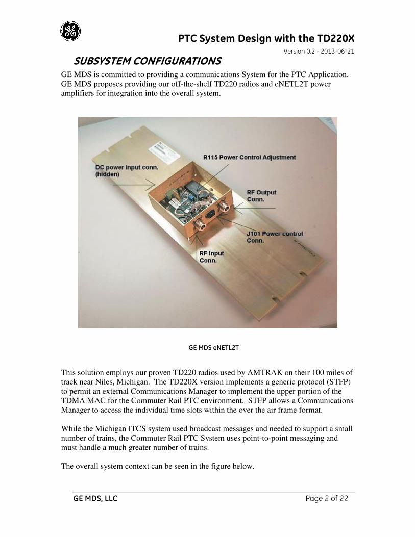
SUBSYSTEM CONFIGURATIONS GE MDS is committed to providing a communications System for the PTC Application.
GE MDS proposes providing our off-the-shelf TD220 radios and eNETL2T power
amplifiers for integration into the overall system.
GE MDS eNETL2T
This solution employs our proven TD220 radios used by AMTRAK on their 100 miles of
track near Niles, Michigan. The TD220X version implements a generic protocol (STFP)
to permit an external Communications Manager to implement the upper portion of the
TDMA MAC for the Commuter Rail PTC environment. STFP allows a Communications
Manager to access the individual time slots within the over the air frame format.
While the Michigan ITCS system used broadcast messages and needed to support a small
number of trains, the Commuter Rail PTC System uses point-to-point messaging and
must handle a much greater number of trains.
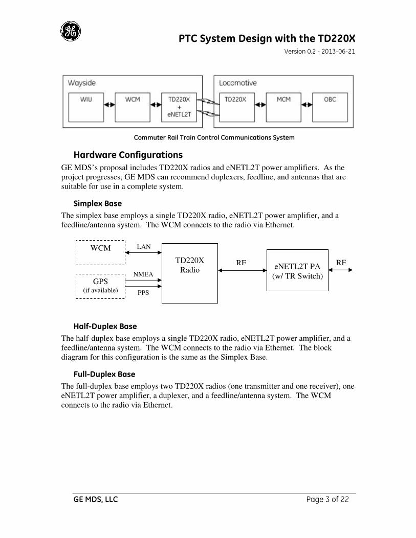
The overall system context can be seen in the figure below.
PTC System Design with the TD220X Version 0.2 - 2013-06-21
GE MDS, LLC Page 3 of 22
Commuter Rail Train Control Communications System
Hardware Configurations
GE MDS’s proposal includes TD220X radios and eNETL2T power amplifiers. As the
project progresses, GE MDS can recommend duplexers, feedline, and antennas that are
suitable for use in a complete system.
Simplex Base
The simplex base employs a single TD220X radio, eNETL2T power amplifier, and a
feedline/antenna system. The WCM connects to the radio via Ethernet.
Half-Duplex Base
The half-duplex base employs a single TD220X radio, eNETL2T power amplifier, and a
feedline/antenna system. The WCM connects to the radio via Ethernet. The block
diagram for this configuration is the same as the Simplex Base.
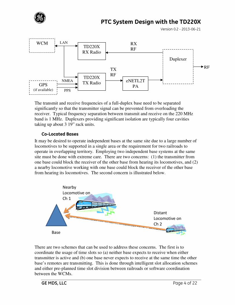
Full-Duplex Base
The full-duplex base employs two TD220X radios (one transmitter and one receiver), one
eNETL2T power amplifier, a duplexer, and a feedline/antenna system. The WCM
connects to the radio via Ethernet.
TD220X
Radio
LAN
RF
eNETL2T PA
(w/ TR Switch)
PPS
NMEA GPS
(if available)
RF
WCM
PTC System Design with the TD220X Version 0.2 - 2013-06-21
GE MDS, LLC Page 4 of 22
The transmit and receive frequencies of a full-duplex base need to be separated
significantly so that the transmitter signal can be prevented from overloading the
receiver. Typical frequency separation between transmit and receive on the 220 MHz
band is 1 MHz. Duplexers providing significant isolation are typically four cavities
taking up about 3 19” rack units.
Co-Located Bases
It may be desired to operate independent bases at the same site due to a large number of
locomotives to be supported in a single area or the requirement for two railroads to
operate in overlapping territory. Employing two independent base systems at the same
site must be done with extreme care. There are two concerns: (1) the transmitter from
one base could block the receiver of the other base from hearing its locomotives, and (2)
a nearby locomotive working with one base could block the receiver of the other base
from hearing its locomotives. The second concern is illustrated below.
There are two schemes that can be used to address these concerns. The first is to
coordinate the usage of time slots so (a) neither base expects to receive when either
transmitter is active and (b) one base never expects to receive at the same time the other
base’s remotes are transmitting. This is done through intelligent slot allocation schemes
and either pre-planned time slot division between railroads or software coordination
between the WCMs.
RF
TD220X
RX Radio
LAN RX
RF
TD220X
TX Radio
TX
RF
eNETL2T
PA PPS
NMEA GPS
(if available)
Duplexer
Nearby
Locomotive on
Ch 1
Distant
Locomotive on
Ch 2
Base
WCM
PTC System Design with the TD220X Version 0.2 - 2013-06-21
GE MDS, LLC Page 5 of 22
The second scheme is to provide enough isolation between units so that any transmitter
can be active when any receiver expects to receive. The isolation-based scheme is
problematic in that sufficient filter networks are physically large. Further, frequencies
must be separated by a significant amount. For example, a co-location plan used in an
RCL application in Houston, TX uses 217.8 MHz TX/218.8 MHz RX for one base and
220.10625 MHz TX/221.10625 MHz RX for the other. Note that 1 MHz separation is
used between the associated transmitters and receivers, while the minimum separation
between the independent receiver and transmitter is 1.30625 MHz. The filter network for
this configuration takes up the better part of a six-foot high 19” rack. As can be easily
seen from this example, it is much more desirable to employ a scheme where timeslots
are not reused at the same site (i.e. the first scheme).
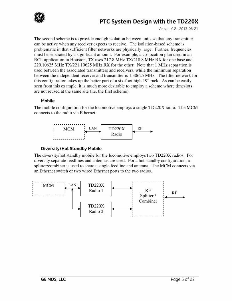
Mobile
The mobile configuration for the locomotive employs a single TD220X radio. The MCM
connects to the radio via Ethernet.
Diversity/Hot Standby Mobile
The diversity/hot standby mobile for the locomotive employs two TD220X radios. For
diversity separate feedlines and antennas are used. For a hot standby configuration, a
splitter/combiner is used to share a single feedline and antenna. The MCM connects via
an Ethernet switch or two wired Ethernet ports to the two radios.
TD220X
Radio
LAN RF
TD220X
Radio 1
LAN
TD220X
Radio 2
RF
Splitter /
Combiner
RF
MCM
MCM

PTC System Design with the TD220X Version 0.2 - 2013-06-21
GE MDS, LLC Page 6 of 22
TDMA MAC The TD220 is a Time Division Multiple Access (TDMA) Radio. The radio divides each
second into 8 equal length 125 ms time slots. The radio is able to transmit or receive one
message in each time slot.
Over the Air (OTA) Message Format
The OTA message is 148 bytes long. It consists of a 12-byte Header, a 117-byte payload
area, a 2-byte CRC value, 16 bytes FEC Code Words and a Guard Byte.
The message header contains bit patterns and values allowing the radio to obtain bit and
Byte synchronization. The Zone and Time Slot information allow Mobiles to
synchronize their time slots using messages from Base radios. The Zone and Time Slot
values are also passed up through the radio and are available to external equipment for
system monitoring.
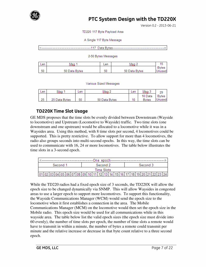
Message Payload Area
The radio can concatenate smaller messages into the 117-byte payload space. These
concatenated messages will be separated by the receiving radio and sent to the local
equipment in separate STFP messages.
PTC System Design with the TD220X Version 0.2 - 2013-06-21
GE MDS, LLC Page 7 of 22
TD220X Time Slot Usage
GE MDS proposes that the time slots be evenly divided between Downstream (Wayside
to locomotive) and Upstream (Locomotive to Wayside) traffic. Two time slots (one
downstream and one upstream) would be allocated to a locomotive while it was in a
Waysides area. Using this method, with 8 time slots per second, 4 locomotives could be
supported. This is pretty restrictive. To allow support for more than 4 locomotives, the
radio also groups seconds into multi-second epochs. In this way, the time slots can be
used to communicate with 16, 24 or more locomotives. The table below illustrates the
time slots in a 3-second epoch.
While the TD220 radios had a fixed epoch size of 3 seconds, the TD220X will allow the
epoch size to be changed dynamically via SNMP. This will allow Waysides in congested
areas to use a larger epoch to support more locomotives. To support this functionality,
the Wayside Communications Manager (WCM) would send the epoch size to the
locomotive when it first establishes a connection in the area. The Mobile
Communications Manager (MCM) on the locomotive would then set the epoch size in the
Mobile radio. This epoch size would be used for all communications while in this
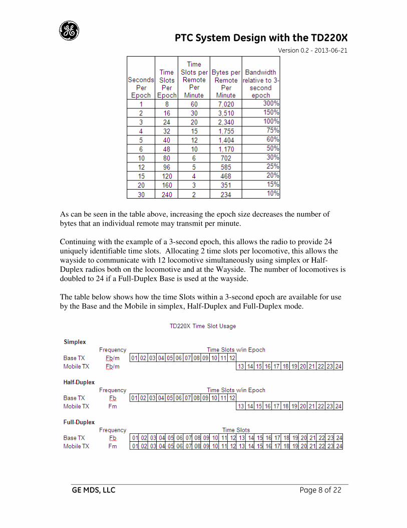
wayside area. The table below list the valid epoch sizes (the epoch size must divide into
60 evenly), the number of time slots per epoch, the number of time slots a remote would
have to transmit in within a minute, the number of bytes a remote could transmit per
minute and the relative increase or decrease in that byte count relative to a three second
epoch.
PTC System Design with the TD220X Version 0.2 - 2013-06-21
GE MDS, LLC Page 8 of 22
As can be seen in the table above, increasing the epoch size decreases the number of
bytes that an individual remote may transmit per minute.
Continuing with the example of a 3-second epoch, this allows the radio to provide 24
uniquely identifiable time slots. Allocating 2 time slots per locomotive, this allows the
wayside to communicate with 12 locomotive simultaneously using simplex or Half-
Duplex radios both on the locomotive and at the Wayside. The number of locomotives is
doubled to 24 if a Full-Duplex Base is used at the wayside.
The table below shows how the time Slots within a 3-second epoch are available for use
by the Base and the Mobile in simplex, Half-Duplex and Full-Duplex mode.
PTC System Design with the TD220X Version 0.2 - 2013-06-21
GE MDS, LLC Page 9 of 22
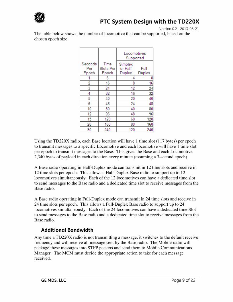
The table below shows the number of locomotive that can be supported, based on the
chosen epoch size.
Using the TD220X radio, each Base location will have 1 time slot (117 bytes) per epoch
to transmit messages to a specific Locomotive and each locomotive will have 1 time slot
per epoch to transmit messages to the Base. This gives the Base and each Locomotive
2,340 bytes of payload in each direction every minute (assuming a 3-second epoch).
A Base radio operating in Half-Duplex mode can transmit in 12 time slots and receive in
12 time slots per epoch. This allows a Half-Duplex Base radio to support up to 12
locomotives simultaneously. Each of the 12 locomotives can have a dedicated time slot
to send messages to the Base radio and a dedicated time slot to receive messages from the
Base radio.
A Base radio operating in Full-Duplex mode can transmit in 24 time slots and receive in
24 time slots per epoch. This allows a Full-Duplex Base radio to support up to 24
locomotives simultaneously. Each of the 24 locomotives can have a dedicated time Slot
to send messages to the Base radio and a dedicated time slot to receive messages from the
Base radio.
Additional Bandwidth
Any time a TD220X radio is not transmitting a message, it switches to the default receive
frequency and will receive all message sent by the Base radio. The Mobile radio will
package these messages into STFP packets and send them to Mobile Communications
Manager. The MCM must decide the appropriate action to take for each message
received.
PTC System Design with the TD220X Version 0.2 - 2013-06-21
GE MDS, LLC Page 10 of 22
This feature can be used to gain downstream bandwidth. The Wayside Communications
Manager can transmit “general interest” message in any Base transmit time slot that has
some room in it. Administrative messages such as a time slot allocation table or a time
slot request could be sent at any time.
There may also be ACSES messages of “general interest” to all locomotives in the area.
STFP PROTOCOL To provide the most flexibility, the TD220X radio acts as a “simple” conduit for
messages between Wayside and locomotive equipment. “Upper level” Media Access
Controller (MAC) logic and functionality are performed by equipment external to the
TD220X radio. The TD220X radio supports the GE MDS open STFP protocol that
allows ACSES equipment to use the TD220X radios to transmit and receive messages
over the air.
The radio provides the lower level Media Access Controller (MAC) functionality of the
communications link between the Wayside equipment and the equipment on the
Locomotive. This lower level MAC functionality includes accurately tracking the multi-
second epoch and TDMA time slots, passing payload received over the air to a
configured IP address and transmitting payload received via UDP using the specified
time slot within the epoch, frequency and output power level.
The radio also implements Forward Error Correction (FEC) to detect and correct errors
introduced due to the movement of the locomotive. Before each message is transmitted
over the air, the transmitting radio calculates and appends a 2 byte CRC and 16 bytes of
FEC code words to the message. The FEC code words allow the receiving radio to detect
and correct bit errors within the message while the CRC allows the receiving radio to
determine if all bit errors have been corrected and, therefore, the message is correct.
The upper level MAC functionality is performed by equipment external to the TD220X
radio. This functionality includes:
1. Ensuring that messages get sent in the first timeslot of a second periodically to
permit mobiles to synchronize their TDMA slots with the base.
2. Managing time slot usage (possibly by using dynamic time slot assignment).
3. Sending ACSES Payload to the radio via STFP message to instruct the radio
when (second and time slot) and how (Frequency and Output Power Level) the
payload should be transmitted.
4. Configure the radio’s receive frequency.
At the Wayside, the Wayside Interface Unit (WIU) contains the controlling logic for the
locomotives within the area of this wayside. The WIU send ACSES messages to the
Wayside Communications Manager (WCM). The WCM then determines which time slot
to use to communicate with the chosen locomotive. It constructs the appropriate STFP
message and sends it to the TD220X Base radio. The Base radio transmits the ACSES
PTC System Design with the TD220X Version 0.2 - 2013-06-21
GE MDS, LLC Page 11 of 22
payload using the Second, Time slot, Frequency and Power specified in the STFP
message.
On the locomotive, the Mobile radio receives the message over the air and passes it onto
the Mobile Communications Manager (MCM) in an STFP message. The MCM then
converts the message to an ACSES message and passes it onto the On Board Computer
(OBC).
Messages from the OBC to the WIU will use the reverse path.
RADIO SYNCHRONIZATION Both Base and Mobile radios must have precisely synchronized clocks in order for the
TDMA communications to work properly. The system has the potential for sending a
message every time slot of every second with only one 1 millisecond separating the
messages. A radio transmitting at an incorrect time can disrupt all PTC communications
within the area.
Base Radio Timing
The Base radios are the master timekeepers of the TD220X radio system. In turn, Base
radios rely on timing information from GPS units for their precise synchronization. A
Base radio uses the Time Of Day (TOD) information from the GPS NMEA GGA
sentence to precisely set its System Clock so it can accurately determine the second
within an epoch. The Base radio uses the GPS Pulse Per Second (PPS) signal to
precisely track the start of each second. The start of each time slot within a second is
then based on this start of second event.
Base Radios without GPS Access
To support wayside locations where GPS units cannot receive sufficient satellite signals
to work (such as in long tunnels), the TD220X Base radios will implement the Precision
Time Protocol (PTP v2, IEEE 1588), which will allow a Base Radio without GPS access
to establish accurate timing, based on IP messages exchanged with a PTP Grandmaster
device. Any device that supports PTP V2 may be used as the Grandmaster (such as the
Spectracom SecureSync). This Grandmaster device would need to be positioned such
that it could get a GPS Lock. A LAN connection is required between the Base radio and
the PTP Grandmaster to support this functionality.
Mobile Radio Synchronization
Mobile radios will not have access to GPS information. The TD220X Mobile radios
synchronize based upon the receipt of a message from a Base radio in the first time slot
of any second. The Mobile uses the header information of these Beacons to synchronize
their TOD and time slot clock. The payload of these Beacon messages is not used as a
part of this synchronization. Only the header information is used.
PTC System Design with the TD220X Version 0.2 - 2013-06-21
GE MDS, LLC Page 12 of 22
It is important that the Wayside Communications Manager send a message (any message)
in the first time slot of a second periodically. The Mobile radio will lose synchronization
lock, go into an alarm state and stop transmitting if it does not receive a Beacon message
every N seconds where N is coded as 6 seconds in our current implementation.
FREQUENCY ASSIGNMENT Careful radio system planning is required to optimize performance and minimize co-
channel interference. Base TX frequencies should be taken from one end of the available
frequency range while Mobile TX frequencies should be taken from the other. Adjacent
bases should be assigned frequencies that are as far apart from one another as practical.
In coordinating channel use for coverage of a PTC system, many spatial channel
assignment schemes have been introduced. Most schemes employ omnidirectional
antennas for even radio coverage and/or a single channel per base. A scheme that
deserves some thought is one that employs directional antennas and two or more channels
at each base site to allow closer channel reuse by counting on the front to back ratio
provided by directional antennas.
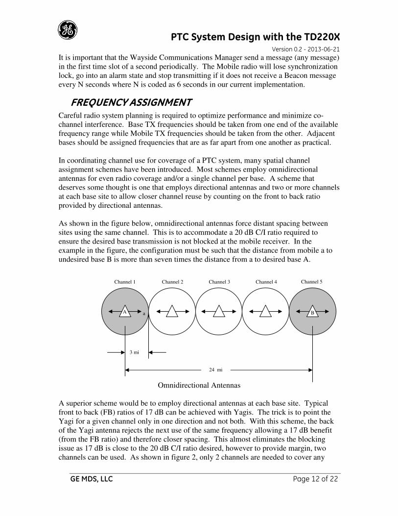
As shown in the figure below, omnidirectional antennas force distant spacing between
sites using the same channel. This is to accommodate a 20 dB C/I ratio required to
ensure the desired base transmission is not blocked at the mobile receiver. In the
example in the figure, the configuration must be such that the distance from mobile a to
undesired base B is more than seven times the distance from a to desired base A.
Omnidirectional Antennas
A superior scheme would be to employ directional antennas at each base site. Typical
front to back (FB) ratios of 17 dB can be achieved with Yagis. The trick is to point the
Yagi for a given channel only in one direction and not both. With this scheme, the back
of the Yagi antenna rejects the next use of the same frequency allowing a 17 dB benefit
(from the FB ratio) and therefore closer spacing. This almost eliminates the blocking
issue as 17 dB is close to the 20 dB C/I ratio desired, however to provide margin, two
channels can be used. As shown in figure 2, only 2 channels are needed to cover any
3 mi
24 mi
a
Channel 1 Channel 2 Channel 3 Channel 4 Channel 5
B A
PTC System Design with the TD220X Version 0.2 - 2013-06-21
GE MDS, LLC Page 13 of 22
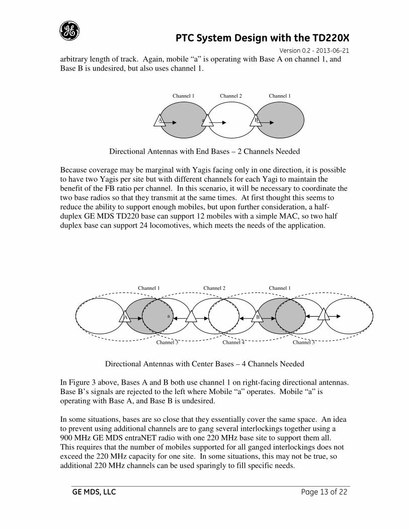
arbitrary length of track. Again, mobile “a” is operating with Base A on channel 1, and
Base B is undesired, but also uses channel 1.
Directional Antennas with End Bases – 2 Channels Needed
Because coverage may be marginal with Yagis facing only in one direction, it is possible
to have two Yagis per site but with different channels for each Yagi to maintain the
benefit of the FB ratio per channel. In this scenario, it will be necessary to coordinate the
two base radios so that they transmit at the same times. At first thought this seems to
reduce the ability to support enough mobiles, but upon further consideration, a half-
duplex GE MDS TD220 base can support 12 mobiles with a simple MAC, so two half
duplex base can support 24 locomotives, which meets the needs of the application.
Directional Antennas with Center Bases – 4 Channels Needed
In Figure 3 above, Bases A and B both use channel 1 on right-facing directional antennas.
Base B’s signals are rejected to the left where Mobile “a” operates. Mobile “a” is
operating with Base A, and Base B is undesired.
In some situations, bases are so close that they essentially cover the same space. An idea
to prevent using additional channels are to gang several interlockings together using a
900 MHz GE MDS entraNET radio with one 220 MHz base site to support them all.
This requires that the number of mobiles supported for all ganged interlockings does not
exceed the 220 MHz capacity for one site. In some situations, this may not be true, so
additional 220 MHz channels can be used sparingly to fill specific needs.
A a B
Channel 1 Channel 1 Channel 2
a
Channel 1 Channel 1 Channel 2
Channel 3
A
Channel 4
B
Channel 3
PTC System Design with the TD220X Version 0.2 - 2013-06-21
GE MDS, LLC Page 14 of 22
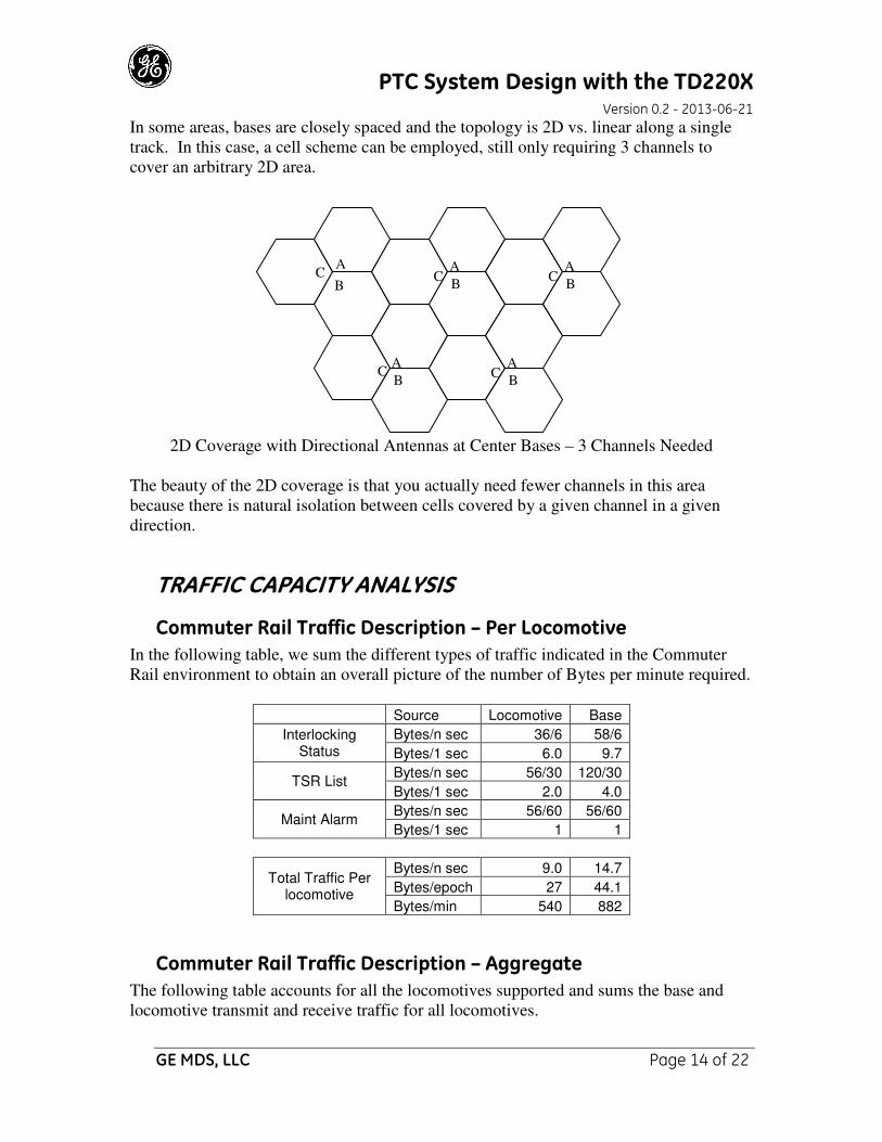
In some areas, bases are closely spaced and the topology is 2D vs. linear along a single
track. In this case, a cell scheme can be employed, still only requiring 3 channels to
cover an arbitrary 2D area.
2D Coverage with Directional Antennas at Center Bases – 3 Channels Needed
The beauty of the 2D coverage is that you actually need fewer channels in this area
because there is natural isolation between cells covered by a given channel in a given
direction.
TRAFFIC CAPACITY ANALYSIS
Commuter Rail Traffic Description – Per Locomotive
In the following table, we sum the different types of traffic indicated in the Commuter
Rail environment to obtain an overall picture of the number of Bytes per minute required.
Source Locomotive Base
Interlocking Status
Bytes/n sec 36/6 58/6
Bytes/1 sec 6.0 9.7
TSR List Bytes/n sec 56/30 120/30
Bytes/1 sec 2.0 4.0
Maint Alarm Bytes/n sec 56/60 56/60
Bytes/1 sec 1 1
Total Traffic Per locomotive
Bytes/n sec 9.0 14.7
Bytes/epoch 27 44.1
Bytes/min 540 882
Commuter Rail Traffic Description – Aggregate
The following table accounts for all the locomotives supported and sums the base and
locomotive transmit and receive traffic for all locomotives.
A
B C
B
A C
A
B C
A
B C
A
B C

PTC System Design with the TD220X Version 0.2 - 2013-06-21
GE MDS, LLC Page 15 of 22
Locomotives Bytes/min per
Locomotive Bytes/min
Base RX Traffic for 12 locomotives 12 540 6480
Base TX Traffic for 12 locomotives 12 882 10584
Base RX Traffic for 24 locomotives 24 540 12960
Base TX Traffic for 24 locomotives 24 882 21168
Capacity of the GE MDS Proposed TD220X Radio
The following table sums the traffic capacity provided by the GE MDS TD220X TDMA
scheme.
Total capacity
Bytes/ Sec
Bytes per EPOCH Bytes/Min
Half-Duplex Base RX Capacity 468 1404 28080
Half-Duplex Base TX Capacity 468 1404 28080
Full-Duplex Base RX Capacity 936 2808 56160
Full-Duplex Base TX Capacity 936 2808 56160
Simplex/Half-Duplex Mobile 117 2340
Comparison of Commuter Rail Traffic Requirement vs. TD220X Capacity
As can be seen in the following table, the TD220X provides sufficient capacity for the
traffic model provided for the Commuter Rail environment.
Commuter Rail Traffic
Requirement
TD220X Capacity
(assuming a 3-second epoch)
Excess Capacity
Source Bytes/Min. Bytes/Min %
Locomotive 540 2340 76.92%
Base RX Traffic for 12 locomotives 6480 28080 76.92%
Base TX Traffic for 12 Locomotives 10584 28080 62.31%
Base RX Traffic for 24 locomotives 12960 56160 76.92%
Base TX Traffic for 24 Locomotives 21168 56160 62.31%
PTC System Design with the TD220X Version 0.2 - 2013-06-21
GE MDS, LLC Page 16 of 22
APPLICATION OF FEC TO WIRELESS RAIL COMMUNICATIONS
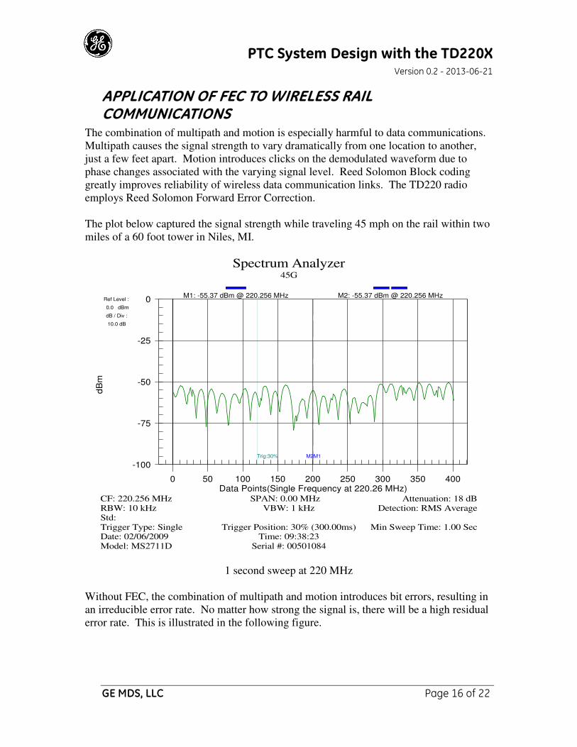
The combination of multipath and motion is especially harmful to data communications.
Multipath causes the signal strength to vary dramatically from one location to another,
just a few feet apart. Motion introduces clicks on the demodulated waveform due to
phase changes associated with the varying signal level. Reed Solomon Block coding
greatly improves reliability of wireless data communication links. The TD220 radio
employs Reed Solomon Forward Error Correction.
The plot below captured the signal strength while traveling 45 mph on the rail within two
miles of a 60 foot tower in Niles, MI.
-100
-75
-50
-25
0
0 50 100 150 200 250 300 350 400
Ref Level :
0.0 dBm
dB / Div :
10.0 dB
M1M2Trig:30%
Spectrum Analyzer45G
Model: MS2711D Serial #: 00501084Date: 02/06/2009 Time: 09:38:23Trigger Type: Single Trigger Position: 30% (300.00ms) Min Sweep Time: 1.00 SecStd: RBW: 10 kHz VBW: 1 kHz Detection: RMS AverageCF: 220.256 MHz SPAN: 0.00 MHz Attenuation: 18 dB
dB
m
Data Points(Single Frequency at 220.26 MHz)
M1: -55.37 dBm @ 220.256 MHz M2: -55.37 dBm @ 220.256 MHz
1 second sweep at 220 MHz
Without FEC, the combination of multipath and motion introduces bit errors, resulting in
an irreducible error rate. No matter how strong the signal is, there will be a high residual
error rate. This is illustrated in the following figure.
PTC System Design with the TD220X Version 0.2 - 2013-06-21
GE MDS, LLC Page 17 of 22
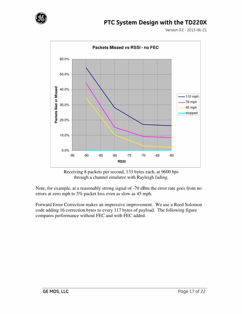
Receiving 8 packets per second, 133 bytes each, at 9600 bps
through a channel emulator with Rayleigh fading.
Note, for example, at a reasonably strong signal of -70 dBm the error rate goes from no
errors at zero mph to 5% packet loss even as slow as 45 mph.
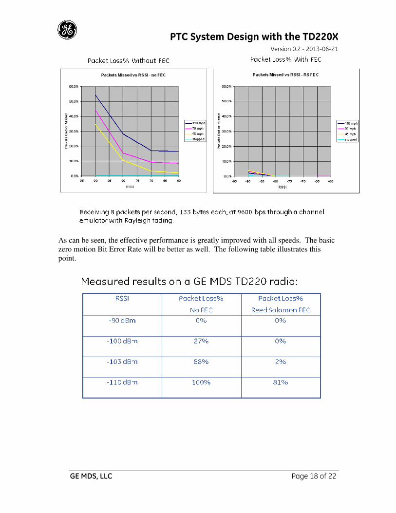
Forward Error Correction makes an impressive improvement. We use a Reed Solomon
code adding 16 correction bytes to every 117 bytes of payload. The following figure
compares performance without FEC and with FEC added.
Packets Missed vs RSSI - no FEC
0.0%
10.0%
20.0%
30.0%
40.0%
50.0%
60.0%
-95 -90 -85 -80 -75 -70 -65 -60
RSSI
Packets
Bad
or M
issed
110 mph
79 mph
45 mph
stopped
PTC System Design with the TD220X Version 0.2 - 2013-06-21
GE MDS, LLC Page 18 of 22
As can be seen, the effective performance is greatly improved with all speeds. The basic
zero motion Bit Error Rate will be better as well. The following table illustrates this
point.

PTC System Design with the TD220X Version 0.2 - 2013-06-21
GE MDS, LLC Page 19 of 22
SUGGESTED TIME SLOT ALLOCATION METHOD While GE MDS does not intend on implementing the slot allocation method described
below, we have prepared this information to serve as a starting point for a system
integrator’s development.
The GE MDS TD220X radio divides each second into 8 equal Time Slots, each 125 ms
long. The radio is able to send or receive a message in each time slot.
Although it has been decided to enhance the radio to support variable sized epochs (as
explained in the proposal), this paper will assume that 3-second epoch is used. Changing
the epoch size will change the number of time slots available to be allocated but the
allocation method will not change.
The radio supports the concept of a three-second epoch. This provides 24 Time slots in
each epoch. Using this TDMA configuration, a Simplex or Half-Duplex Base radio can
support up to 12 locomotives simultaneously and a Full-Duplex Base radio can support
up to 24 locomotives simultaneously.
In this time slot allocation method, the communications for each locomotive utilizes 2
time slots within the epoch. One time slot is for communication from the wayside to the
locomotive, the other is used for communications from the locomotive to the wayside.
Wayside functionality
The Wayside Communications Manager (WCM) or other equipment at the Wayside
locations will transmit a Slot Allocation Map message, through the Base radio, at least
once a second. This should be a fairly small message that can be sent in any time slot
that has room. As a Mobile radio is in Receive Mode if it is not transmitting, Mobiles
will receive and process all messages send by the Base. The Slot Allocation message will
contain a Slot Allocation bit map. Each bit in the bit map will represent the
corresponding time slot within an epoch. If the bit is set, the corresponding time slot is
allocated for use by a locomotive. If the Bit is clear, the corresponding time slot is not
allocated and is available to be requested by a locomotive.
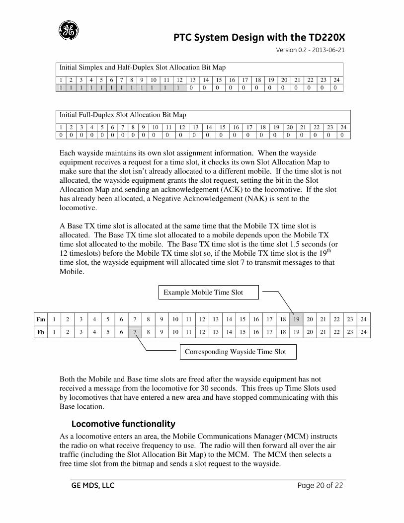
Wayside equipment using a Simplex or Half-Duplex Base radio will always report the
first 12 time slots as allocated. The Simplex and Half-Duplex radio will use these time
slots to transmit to the Mobiles. These time slots will be available in the Full-Duplex
environment as the Full-Duplex Base will be able to both transmit and receive in all time
slots.
PTC System Design with the TD220X Version 0.2 - 2013-06-21
GE MDS, LLC Page 20 of 22
Initial Simplex and Half-Duplex Slot Allocation Bit Map
1 2 3 4 5 6 7 8 9 10 11 12 13 14 15 16 17 18 19 20 21 22 23 24
1 1 1 1 1 1 1 1 1 1 1 1 0 0 0 0 0 0 0 0 0 0 0 0
Initial Full-Duplex Slot Allocation Bit Map
1 2 3 4 5 6 7 8 9 10 11 12 13 14 15 16 17 18 19 20 21 22 23 24
0 0 0 0 0 0 0 0 0 0 0 0 0 0 0 0 0 0 0 0 0 0 0 0
Each wayside maintains its own slot assignment information. When the wayside
equipment receives a request for a time slot, it checks its own Slot Allocation Map to
make sure that the slot isn’t already allocated to a different mobile. If the time slot is not
allocated, the wayside equipment grants the slot request, setting the bit in the Slot
Allocation Map and sending an acknowledgement (ACK) to the locomotive. If the slot
has already been allocated, a Negative Acknowledgement (NAK) is sent to the
locomotive.
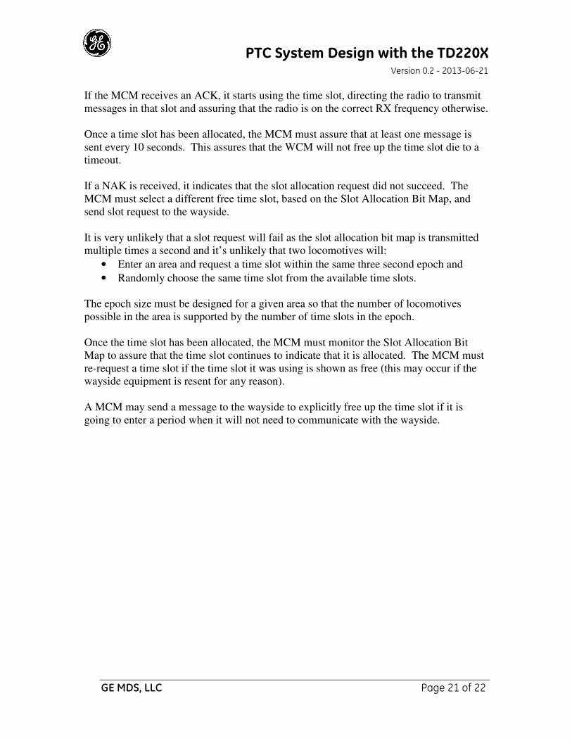
A Base TX time slot is allocated at the same time that the Mobile TX time slot is
allocated. The Base TX time slot allocated to a mobile depends upon the Mobile TX
time slot allocated to the mobile. The Base TX time slot is the time slot 1.5 seconds (or
12 timeslots) before the Mobile TX time slot so, if the Mobile TX time slot is the 19th
time slot, the wayside equipment will allocated time slot 7 to transmit messages to that
Mobile.
Fm 1 2 3 4 5 6 7 8 9 10 11 12 13 14 15 16 17 18 19 20 21 22 23 24
Fb 1 2 3 4 5 6 7 8 9 10 11 12 13 14 15 16 17 18 19 20 21 22 23 24
Both the Mobile and Base time slots are freed after the wayside equipment has not
received a message from the locomotive for 30 seconds. This frees up Time Slots used
by locomotives that have entered a new area and have stopped communicating with this
Base location.
Locomotive functionality
As a locomotive enters an area, the Mobile Communications Manager (MCM) instructs
the radio on what receive frequency to use. The radio will then forward all over the air
traffic (including the Slot Allocation Bit Map) to the MCM. The MCM then selects a
free time slot from the bitmap and sends a slot request to the wayside.
Example Mobile Time Slot
Corresponding Wayside Time Slot
PTC System Design with the TD220X Version 0.2 - 2013-06-21
GE MDS, LLC Page 21 of 22
If the MCM receives an ACK, it starts using the time slot, directing the radio to transmit
messages in that slot and assuring that the radio is on the correct RX frequency otherwise.
Once a time slot has been allocated, the MCM must assure that at least one message is
sent every 10 seconds. This assures that the WCM will not free up the time slot die to a
timeout.
If a NAK is received, it indicates that the slot allocation request did not succeed. The
MCM must select a different free time slot, based on the Slot Allocation Bit Map, and
send slot request to the wayside.
It is very unlikely that a slot request will fail as the slot allocation bit map is transmitted
multiple times a second and it’s unlikely that two locomotives will:
• Enter an area and request a time slot within the same three second epoch and
• Randomly choose the same time slot from the available time slots.
The epoch size must be designed for a given area so that the number of locomotives
possible in the area is supported by the number of time slots in the epoch.
Once the time slot has been allocated, the MCM must monitor the Slot Allocation Bit
Map to assure that the time slot continues to indicate that it is allocated. The MCM must
re-request a time slot if the time slot it was using is shown as free (this may occur if the
wayside equipment is resent for any reason).
A MCM may send a message to the wayside to explicitly free up the time slot if it is
going to enter a period when it will not need to communicate with the wayside.
PTC System Design with the TD220X Version 0.2 - 2013-06-21
GE MDS, LLC Page 22 of 22
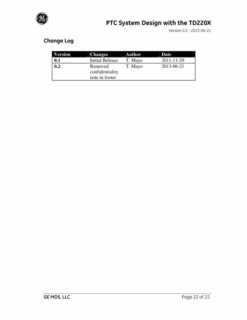
Change Log
Version Changes Author Date
0.1 Initial Release T. Mayo 2011-11-29
0.2 Removed
confidentiality
note in footer
T. Mayo 2013-06-21