ptech: msw for gasification to h2 and other gases. 1... · plasma gasification technology is...
TRANSCRIPT

0
PTech: MSW for gasification to H2 and
other gases.
DR. JOSÉ RAMOS SARAVIA
César Díaz Leigh, from UTEC (University of
Engineering and Technology)
Sebastián Amaru Escalante Ccoyllo, from UTEC
(University of Engineering and Technology)
EmIlio Roger Grandy Gonzáles, from UNI (National
University of Engineering)
Juan Antonio Lorenzo Loo Kung Baffigo, from UTEC
(University of Engineering and Technology)
Cynthia Mori Córdova, from UNI (National University of Engineering)
Fabian Mauricio Rivera Verde, from UTEC (University of Engineering and Technology)
Wilmar Huaccachi Herrera, from UNI (National University of Engineering)
1
Executive Summary
On Perú, treatment and elimination of municipal solid waste (MSW) is responsibility of local
authority and Health Minister. At national level, on 2012 it has generated 4.68 millions of ton of
MSW. In Lima, most of this waste is disposed in authorized landfills. However the rest of this
waste does not have a good treatment and is incinerated. On one side, energy is a solution and
at the same time a problem for a sustainable development, because of being necessary for
everything, its current use constitutes the main source of contamination of the environment.
Plasma gasification is one of the technologies which is being develop on the last years in order
to give a potential use of this problem (MSW). On the other hand, hydrogen is a suitable fuel for
refineries which uses it in their desulphurization processes. A combine facility of electrolysis and
gasification by MSW could attend the hydrogen demand in a refinery. On the next pages, an
evaluation of the technical and economical feasibility of the implementation in Peruvian
refineries is made in order to produce hydrogen and other gases to be commercially sold [1].
The present report is developed as an alternative of the problematic MSW bad treated in Lima.
The report is compound by a methodology of 3 parts: Research-phase: where the team collects
all the information available of the necessity on the refinery. On the design-phase: the team
collects information about the technologies available on the market and how could this
technology help us on the facility. Finally, on the post-design-phase, an evaluation of the
environmental analysis, economics and legally are make to suggest a possible optimization and
analyze if this implementation is feasible or not.
Commented [1]: http://www.ods.org.pe/material-de-consulta/24-informe-anual-de-residuos-solidos-municipales-y-no-municipales-en-el-peru-gestion-2012/file
2
Table of Contents 1. Introduction
a. Description and proposal solution b. Resources evaluation c. Clients and final uses
2. Project Methodology
3. Conceptual Design
a. General plant scheme b. Subsystem production
i. Desalination process ii. Hydrogen and oxygen production iii. Syngas production iv. Gases purification
1. Syngas purification 2. Hydrogen purification
v. Methanation process
4. Technical assessment
5. Economic assessment a. Investments costs b. Operation costs
6. Environmental impact and security analysis
a. Environmental impact analysis b. Specific consideration security for the resources
7. Siting
8. Design security and plant operation
9. Marketing and customer education
10. References

3
1. 1. Introduction
Electricity supplying to peruvian energy market is based on hydroelectric (54,6 %), natural gas (40,5 %) , and renewable - solar and wind (less than 5%) - power plants [2]. It means that there is an opportunity for renewable energy - such as municipal solid waste (MSW) or biomass - to participate in the peruvian energy matrix. MSW can be converted to fuel (hydrogen, methane, etc.) and/or electricity. On the one side, in Lima city (Peru), MSW production is 9 ton/day, and it will increase to 16 ton/day for year 2034 [3]. On the other side, some companies are hydrogen-intensive consumer, such as “La Pampilla” refinery, where hydrogen is fundamental to desulphurization processes. This refinery is located 1,5 km from the beach at the coast of Callao (Lima) refinery, which is located 1,5 km from the beach at the coast of Callao. We will design a facility supplying hydrogen to “La Pampilla” refinery. The facility will integrate the following main processes: (i) water desalination from sea-water, to feed the (ii) electrolysis, to produce oxygen and hydrogen, (iii) plasma gasification to produce syngas using oxygen (from electrolyzer), and (iv) syngas cleaning, finally, a (v) methanation process to produce methane and other gases such as carbon dioxide and methane. All processes will use electricity from the public grid. By-products (methane and carbon dioxide) of the facility will be commercialized locally.
2. 2. Project Design/Methodology
A three phase approach has been implemented to design the facility developed in this report:
(1) Research phase: Data collection. Information regarding the MSW availability, refinery’ hydrogen demand, equipment investment cost and technical specifications, and safety codes and standards were collected.
(2) Design Phase: Sizing equipment. Using technical/economic information, we select
commercial equipment (plasma gasifier, electrolyzer, water desalinator) and evaluate different alternatives matching refinery’ hydrogen demand and MSW availability.
(3) Post-Design Phase: Environmental assessment and safety operation. In addition,
educational material will be prepared.
4
3. 3. Conceptual Design
3.1. 3.1 General plant design
Our project proposes the addition of a facility plant that uses MSW plasma gasification
technology coupled with water electrolysis in order to satisfy the oxygen necessary for
gasification processes. This plant/process consists of an electrolyzer, which will provide
oxygen for gasification process and hydrogen for the refinery and methanation
processes. The plasma gasification reactor will produce the raw syngas. This raw
syngas will pass through purification systems in order to bring high quality syngas. At the
same time, supplied by the oxygen of the electrolysis process and the raw products of
the gasification, methane reactor will produce other gases. Then, all hydrogen produced
will be supplied to pipelines in the refinery to use it directly on their desulphurization
processes. Other products such as methane and carbon dioxide will be storage and sold
them locally.
3.2. 3.2 Seawater desalination
Seawater will be used as input of the oxygen and hydrogen production system. In order
to preserve the electrolyzer in ideal conditions and to increase its efficiency a
desalination system will pre-treat the water.
3.3. 3.3 Production of Hydrogen and Oxygen
Water electrolysis is used in order to separate hydrogen from water through electric
current producing hydrogen and oxygen. Some of the most used technologies are
proton exchange membrane electrolyzer (PEM), alkaline electrolyzer, electrolyzer based
on solid oxides and reversible fuel cells.
Hydrogenics Inc. has been selected as the provider of the electrolyzer technology. According to an investigation made by ECS (Electrochemical Society) in 2010, the PEM technology is more advantageous than alkaline due his high efficiency. Thus, “HyLIZER 3000” of 15MW will be used. This equips counts with a 3000Nm3/h flow. Also, it can help to reduce the energy use of the compressor to storage the hydrogen due machine the exit press (until 35 bar). Besides the purity level obtained of the hydrogen is 99.998% [4]
This equipment will provide 50% of the oxygen required by the plasma gasification reactor while the remaining 50% will come from air separation unit.
The air separation unit extracts the necessary oxygen from air using pressure swing adsorption (PSA). This technology was chosen due to its high reliability, extensive use in other industries and low costs.
The hydrogen produced in this system will be utilized by the refinery covering the 50% of its demand. The other 50% will be send in a methanation reactor in order to produce methane
5
3.4. 3.4 Municipal Solid Waste treatment
MSW will be shredded and dehumidified in order to reduce the plasma torches energy consumption. A belt dryer will be employed due to its simple configuration; perforated belts through which hot steam passes. The hot steam will be produced in a heat exchanger where cold water receives heat from the hot syngas exiting the reactor, thus, no energy consumption will take place in the dehumidifier. Although these types of dryers have a lower moisture discharge capacity, they allow them to operate at low temperatures, thus avoiding unwanted emissions and risk of fire, reducing their cost.
3.5. 3.5 Plasma Gasification Reactor
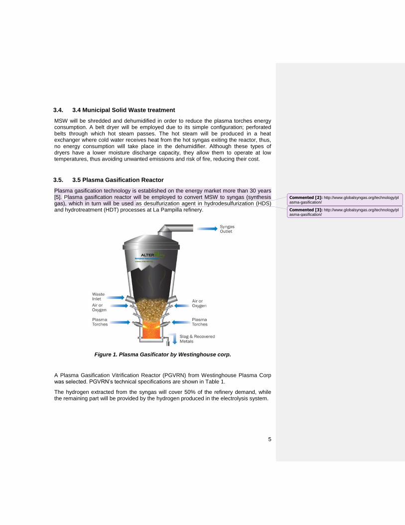
Plasma gasification technology is established on the energy market more than 30 years [5]. Plasma gasification reactor will be employed to convert MSW to syngas (synthesis gas), which in turn will be used as desulfurization agent in hydrodesulfurization (HDS) and hydrotreatment (HDT) processes at La Pampilla refinery.
Figure 1. Plasma Gasificator by Westinghouse corp.
A Plasma Gasification Vitrification Reactor (PGVRN) from Westinghouse Plasma Corp was selected. PGVRN’s technical specifications are shown in Table 1.
The hydrogen extracted from the syngas will cover 50% of the refinery demand, while the remaining part will be provided by the hydrogen produced in the electrolysis system.
Commented [2]: http://www.globalsyngas.org/technology/plasma-gasification/
Commented [3]: http://www.globalsyngas.org/technology/plasma-gasification/

6
3.6. 3.6 Purification Systems
3.6.1. 3.6.1 Syngas purification System
A Syngas purification system is a system that is used to obtain a clean syngas. Syngas typically requires some level of cleanup in order to meet specific requirements for downstream processes. This includes removal of particulate matter, sulfur compounds, chlorine compounds, unreacted hydrocarbons, and heavy metals. These contaminants can plug up reactors, cause corrosion, poison downstream catalysts, or prevent the plant from complying with environmental permits
3.6.2. 3.6.2 Hydrogen Purification System
A hydrogen purification system is a system that is commonly used to obtain a degree of purity of our final product that is hydrogen. But to be able to choose a purification system it must be observed what its use will be, because of this there are these types of systems. First we have of Pressure Swing Adsorption (PSA). With this technology, they can be achieved very high purity hydrogen. Currently it is the most widespread process in any type of refinery for the purification of hydrogen in a steam reforming process due to the high purity with which it is obtained. PSA is a very complex cyclic process that uses fixed beds of solid adsorbent to remove impurities from the gas. These impurities are retained in the adsorbent. There is also the membrane separation system based on selective permeability and separation by cryogenic systems. These systems are not widely used because the hydrogen comes out with a lower percentage of impurity than the PSA method and also are not widely used due to their high investment costs and, above all, their operation.
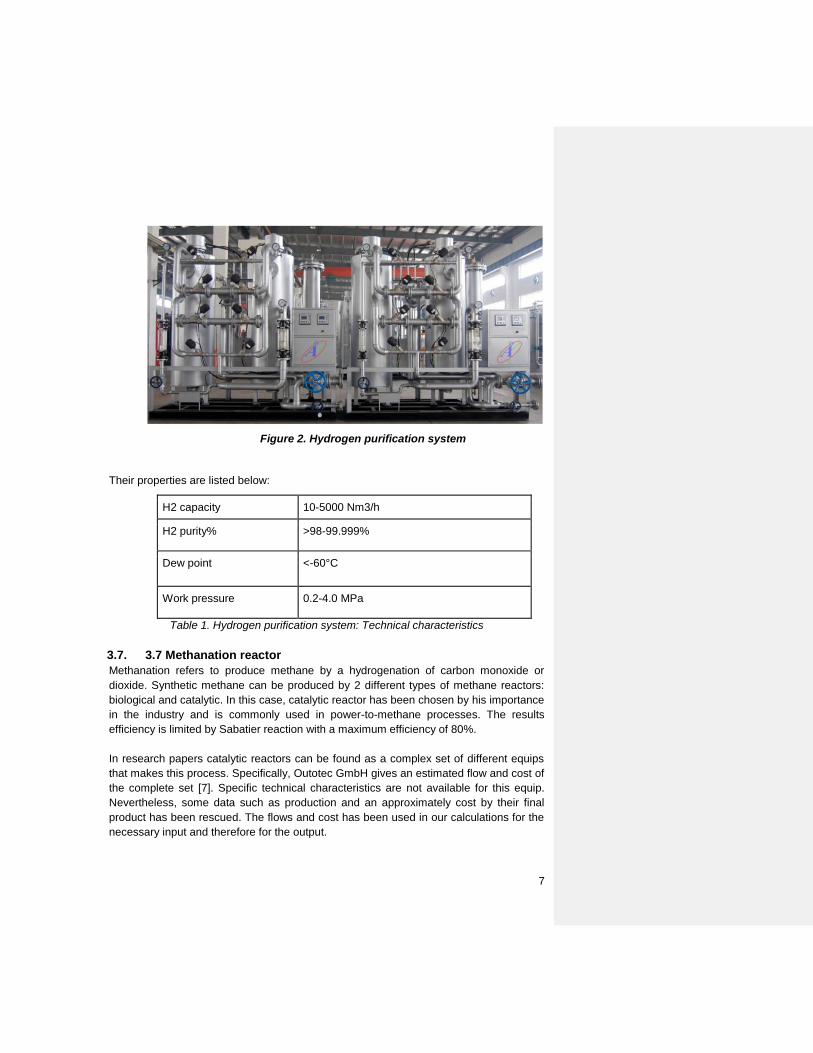
Our system removes oxygen from hydrogen via a catalyst to get high purity H2 after adsorption of drying through the dusty filter. Through one step of purification, the purity can reach to 98-99.999% and dew point can be lower than - 70°C; Through a second purification step, O2 can be lowered down to less than 0.1 ppm and dew point can be lowered to -90°C [6].
7
Figure 2. Hydrogen purification system
Their properties are listed below:
H2 capacity 10-5000 Nm3/h
H2 purity% >98-99.999%
Dew point <-60°C
Work pressure 0.2-4.0 MPa
Table 1. Hydrogen purification system: Technical characteristics
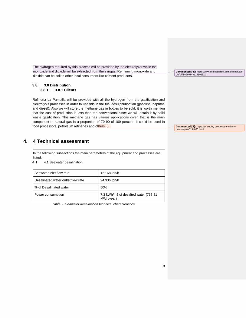
3.7. 3.7 Methanation reactor
Methanation refers to produce methane by a hydrogenation of carbon monoxide or
dioxide. Synthetic methane can be produced by 2 different types of methane reactors:
biological and catalytic. In this case, catalytic reactor has been chosen by his importance
in the industry and is commonly used in power-to-methane processes. The results
efficiency is limited by Sabatier reaction with a maximum efficiency of 80%.
In research papers catalytic reactors can be found as a complex set of different equips
that makes this process. Specifically, Outotec GmbH gives an estimated flow and cost of
the complete set [7]. Specific technical characteristics are not available for this equip.
Nevertheless, some data such as production and an approximately cost by their final
product has been rescued. The flows and cost has been used in our calculations for the
necessary input and therefore for the output.
8
The hydrogen required by this process will be provided by the electrolyzer while the
monoxide and dioxide will be extracted from the syngas. Remaining monoxide and
dioxide can be sell to other local consumers like cement producers.
3.8. 3.8 Distribution
3.8.1. 3.8.1 Clients
Refineria La Pampilla will be provided with all the hydrogen from the gasification and
electrolysis processes in order to use this in the fuel desulphurisation (gasoline, naphtha
and diesel). Also we will store the methane gas in bottles to be sold, it is worth mention
that the cost of production is less than the conventional since we will obtain it by solid
waste gasification. This methane gas has various applications given that is the main
component of natural gas in a proportion of 70-90 of 100 percent. It could be used in
food processors, petroleum refineries and others [8].
4. 4 Technical assessment
In the following subsections the main parameters of the equipment and processes are
listed.
4.1. 4.1 Seawater desalination
Seawater inlet flow rate 12.168 ton/h
Desalinated water outlet flow rate 24.336 ton/h
% of Desalinated water 50%
Power consumption 7.3 kWh/m3 of desalted water (768,81 MWh/year)
Table 2. Seawater desalination technical characteristics
Commented [4]: https://www.sciencedirect.com/science/article/pii/S0960148115301610
Commented [5]: https://sciencing.com/uses-methane-natural-gas-6134860.html

9
4.2. 4.2 Oxygen production
Participation in O2 50.0%
H2O inlet flow rate 9.8568 ton/h
H2O converted 81%
O2 outlet flow rate 8.7624 ton/h
H2 outlet flow rate 1.0944 ton/h
H2O outlet flow rate 2.3112 ton/h
Power consumption 5 kWh/ Nm3_H2 (531321.07 MWh/year)
Table 3. Technical specification of oxygen production
4.3. 4.3 MSW treatment
MSW inlet flow rate 17.02 t/h (146378.88t/year)
Inlet humidity % 44%
Outlet humidity % 17.81%
MSW outlet flow rate 12.56 t/h (108037.17t/year)
Shredder power consumption 360 kW
Dehumidifier power consumption 0 kW
Annual treatment power consumption 3119.04 MWh
Table 4. Technical specification of the MSW treatment
4.4. 4.4 Raw Syngas production
% participation in H2 for refinery 50%
MSW inlet flow rate 12.56 t/h (108037.17t/year)
O2 inlet flow rate 17.5212 ton/h
Plasma torch air consumption 4.3128 ton/h
Vitrified outlet flow rate 3.15 ton/h
Syngas outlet flow rate 35.712 ton/h
10
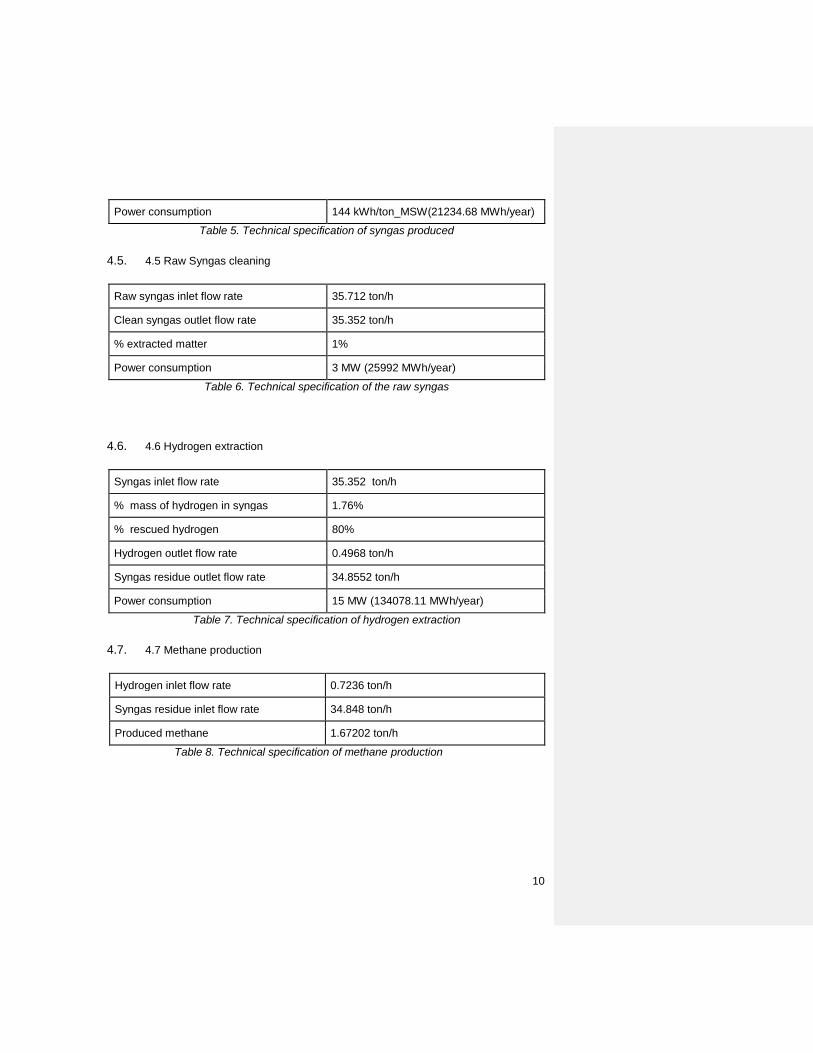
Power consumption 144 kWh/ton_MSW(21234.68 MWh/year)
Table 5. Technical specification of syngas produced
4.5. 4.5 Raw Syngas cleaning
Raw syngas inlet flow rate 35.712 ton/h
Clean syngas outlet flow rate 35.352 ton/h
% extracted matter 1%
Power consumption 3 MW (25992 MWh/year)
Table 6. Technical specification of the raw syngas
4.6. 4.6 Hydrogen extraction
Syngas inlet flow rate 35.352 ton/h
% mass of hydrogen in syngas 1.76%
% rescued hydrogen 80%
Hydrogen outlet flow rate 0.4968 ton/h
Syngas residue outlet flow rate 34.8552 ton/h
Power consumption 15 MW (134078.11 MWh/year)
Table 7. Technical specification of hydrogen extraction
4.7. 4.7 Methane production
Hydrogen inlet flow rate 0.7236 ton/h
Syngas residue inlet flow rate 34.848 ton/h
Produced methane 1.67202 ton/h
Table 8. Technical specification of methane production
11
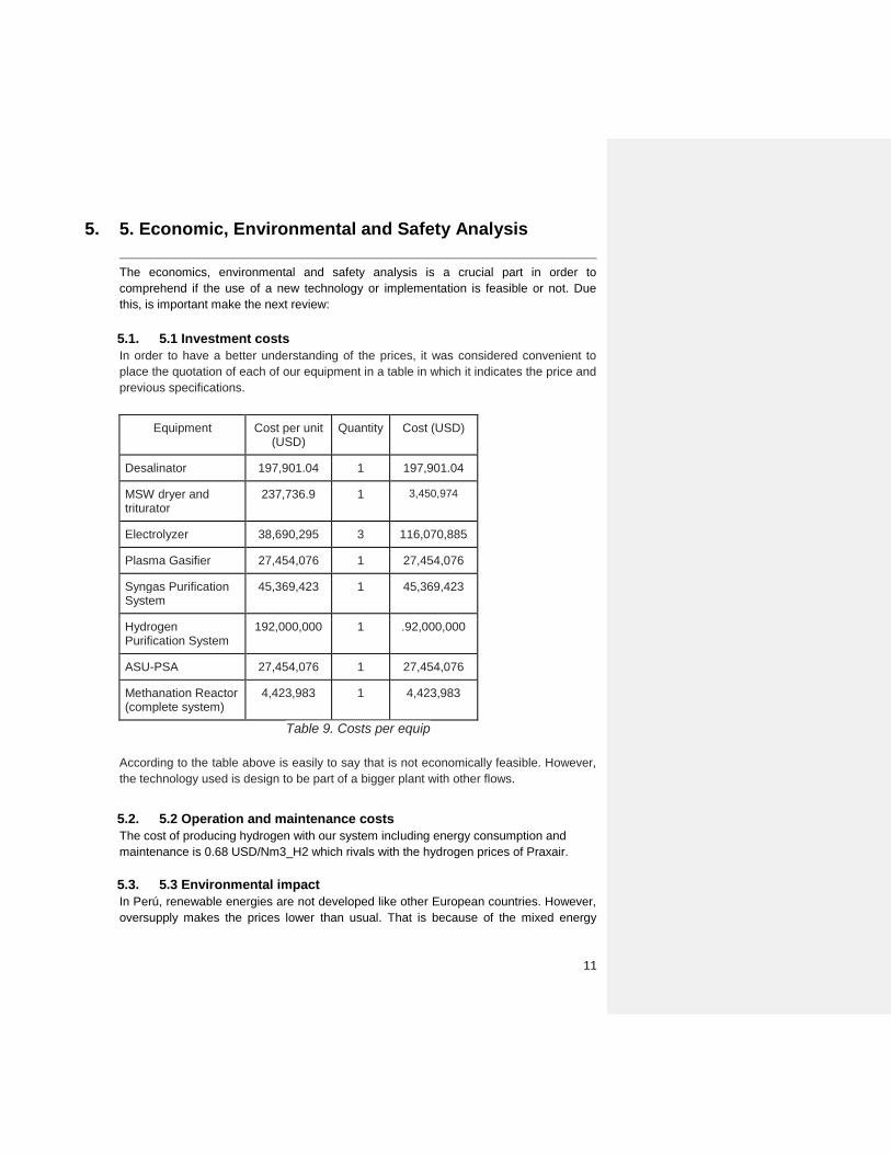
5. 5. Economic, Environmental and Safety Analysis
The economics, environmental and safety analysis is a crucial part in order to
comprehend if the use of a new technology or implementation is feasible or not. Due
this, is important make the next review:
5.1. 5.1 Investment costs
In order to have a better understanding of the prices, it was considered convenient to
place the quotation of each of our equipment in a table in which it indicates the price and
previous specifications.
Equipment Cost per unit (USD)
Quantity Cost (USD)
Desalinator 197,901.04 1 197,901.04
MSW dryer and triturator
237,736.9 1 3,450,974
Electrolyzer 38,690,295 3 116,070,885
Plasma Gasifier 27,454,076 1 27,454,076
Syngas Purification System
45,369,423 1 45,369,423
Hydrogen Purification System
192,000,000 1 .92,000,000
ASU-PSA 27,454,076 1 27,454,076
Methanation Reactor (complete system)
4,423,983 1 4,423,983
Table 9. Costs per equip
According to the table above is easily to say that is not economically feasible. However,
the technology used is design to be part of a bigger plant with other flows.
5.2. 5.2 Operation and maintenance costs
The cost of producing hydrogen with our system including energy consumption and
maintenance is 0.68 USD/Nm3_H2 which rivals with the hydrogen prices of Praxair.
5.3. 5.3 Environmental impact
In Perú, renewable energies are not developed like other European countries. However,
oversupply makes the prices lower than usual. That is because of the mixed energy
12
matrix which we have explained before. Because of this our work seeks to take
advantage of this fact and use it to transform in gas to supply the hydrogen demand in
“La Pampilla” refinery. In fact, one of the advantages of our project is that each
compound will be used in any of our processes or will be sold and commercialized.
Nevertheless, different pollutants are likely to be produced during the process of
gasification and each one will be removed. The principal environmental emission offset
in any plant is the drop of CO2. In our case the emission of CO2 is so lower because we
need to respect laws and norms that regulate CO2 and CO. For example Kyoto Protocol
is a protocol that various industries agreed to reduce emission of six gases of its
greenhouse gases (GHG) initially by the end of 2012, carbon dioxide (CO2), nitrous
oxide (N2O), methane (CH4), (HFC), (PFC), sulfur hexafluoride (SF6), contributed
mainly by industrial activities [Generación eléctrica mediante gasificacion por plasma de
residuos solidos- Tesis de emilio]. Other pollutants are dioxins, TCDD, PCBs,
Hydrochloric acid and CO but this pollutants are produced in less quantities and these
can be controlled[Technical and economic analysis of plasm].
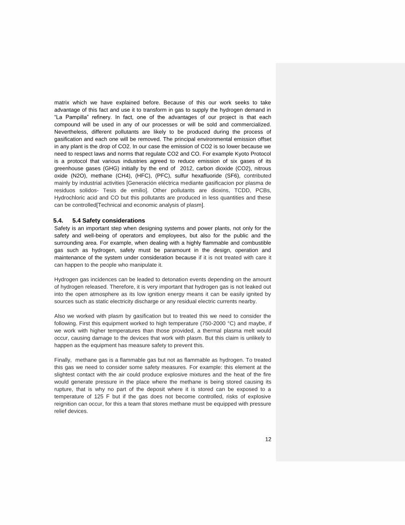
5.4. 5.4 Safety considerations
Safety is an important step when designing systems and power plants, not only for the
safety and well-being of operators and employees, but also for the public and the
surrounding area. For example, when dealing with a highly flammable and combustible
gas such as hydrogen, safety must be paramount in the design, operation and
maintenance of the system under consideration because if it is not treated with care it
can happen to the people who manipulate it.
Hydrogen gas incidences can be leaded to detonation events depending on the amount
of hydrogen released. Therefore, it is very important that hydrogen gas is not leaked out
into the open atmosphere as its low ignition energy means it can be easily ignited by
sources such as static electricity discharge or any residual electric currents nearby.
Also we worked with plasm by gasification but to treated this we need to consider the
following. First this equipment worked to high temperature (750-2000 °C) and maybe, if
we work with higher temperatures than those provided, a thermal plasma melt would
occur, causing damage to the devices that work with plasm. But this claim is unlikely to
happen as the equipment has measure safety to prevent this.
Finally, methane gas is a flammable gas but not as flammable as hydrogen. To treated
this gas we need to consider some safety measures. For example: this element at the
slightest contact with the air could produce explosive mixtures and the heat of the fire
would generate pressure in the place where the methane is being stored causing its
rupture, that is why no part of the deposit where it is stored can be exposed to a
temperature of 125 F but if the gas does not become controlled, risks of explosive
reignition can occur, for this a team that stores methane must be equipped with pressure
relief devices.

13
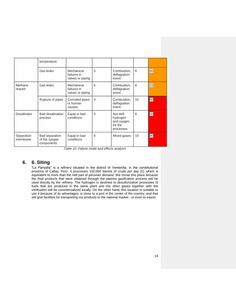
Failure mode and effect analysis
Process Area Failure Mode Potential Causes
Likelihood of failure
Failure Effects
Risk Severity
Overall associated
risk
Electrolysis Oxygen accumulation
Oxygen gas vent blocked
5 Combustion, deflagration event, detonation event
10 50
Water purification failure
Clogged purification membranes, high levels of impurity in source water
6 Impurity and water residue build up
2 12
Gas leaks Mechanical failures in valves or piping
5 Combustion 8 40
Process control and feedback systems
Uncontrolled inflow or outflow of gas in different components
Control system failures
6 Unequal pressure build up, electrolysis and compression failure
6 36
Overpressure effects cause in components
Blockages in piping valve failures or compressor suction leaks
6 Combustion, deflagration event, detonation event
10 60
Gasification Bad condition input flow
Human error 3 Poor syngas, combustion, deflagration event
8 40
Excessive plasma torch
Cooling system error
9 Poor syngas 7 45
14
temperature
Gas leaks Mechanical failures in valves or piping
5 Combustion, deflagration event
8 40
Methane reactor
Gas leaks Mechanical failures in valves or piping
5 Combustion, deflagration event
8 10
Rupture of pipes Corroded pipes or human causes
4 Combustion, deflagration event
10 60
Desalinator Bad desalination process
Equip in bad conditions
4 Not well hydrogen and oxygen for the processes
8 50
Separation membrane
Bad separation of the syngas components
Equip in bad conditions
9 Mixed gases 10 80
Table 10. Failure mode and effects analysis
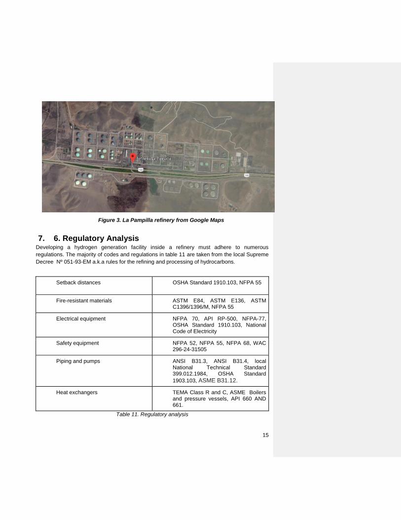
6. 6. Siting “La Pampilla” is a refinery situated in the district of Ventanilla, in the constitutional province of Callao, Perú. It processes 102,000 barrels of crude per day [1], which is equivalent to more than the half part of peruvian demand. We chose this place because the final products that were obtained through the plasma gasification process will be used directly by the refinery. The hydrogen is destined to desulfurization processes of fuels that are produced in the same plant and the other gases together with the vitrification will be commercialized locally. On the other hand, this location is suitable to use it because of its advantages: is close to a port in the center of the country, and that will give facilities for transporting our products to the national market - or even to export.
15
Figure 3. La Pampilla refinery from Google Maps
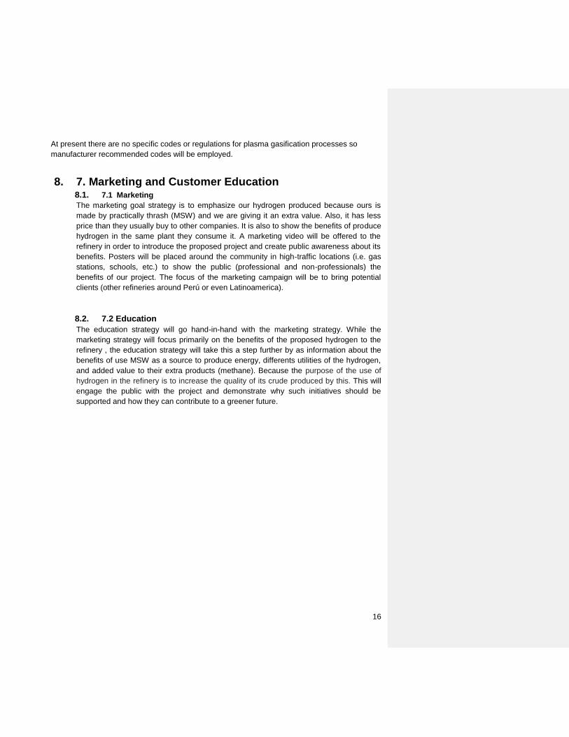
7. 6. Regulatory Analysis Developing a hydrogen generation facility inside a refinery must adhere to numerous
regulations. The majority of codes and regulations in table 11 are taken from the local Supreme
Decree Nº 051-93-EM a.k.a rules for the refining and processing of hydrocarbons.
Setback distances
OSHA Standard 1910.103, NFPA 55
Fire-resistant materials ASTM E84, ASTM E136, ASTM C1396/1396/M, NFPA 55
Electrical equipment NFPA 70, API RP-500, NFPA-77, OSHA Standard 1910.103, National Code of Electricity
Safety equipment NFPA 52, NFPA 55, NFPA 68, WAC 296-24-31505
Piping and pumps ANSI B31.3, ANSI B31.4, local National Technical Standard 399.012.1984, OSHA Standard
1903.103, ASME B31.12.
Heat exchangers TEMA Class R and C, ASME Boilers and pressure vessels, API 660 AND 661.
Table 11. Regulatory analysis
16
At present there are no specific codes or regulations for plasma gasification processes so
manufacturer recommended codes will be employed.
8. 7. Marketing and Customer Education 8.1. 7.1 Marketing
The marketing goal strategy is to emphasize our hydrogen produced because ours is
made by practically thrash (MSW) and we are giving it an extra value. Also, it has less
price than they usually buy to other companies. It is also to show the benefits of produce
hydrogen in the same plant they consume it. A marketing video will be offered to the
refinery in order to introduce the proposed project and create public awareness about its
benefits. Posters will be placed around the community in high-traffic locations (i.e. gas
stations, schools, etc.) to show the public (professional and non-professionals) the
benefits of our project. The focus of the marketing campaign will be to bring potential
clients (other refineries around Perú or even Latinoamerica).
8.2. 7.2 Education
The education strategy will go hand-in-hand with the marketing strategy. While the
marketing strategy will focus primarily on the benefits of the proposed hydrogen to the
refinery , the education strategy will take this a step further by as information about the
benefits of use MSW as a source to produce energy, differents utilities of the hydrogen,
and added value to their extra products (methane). Because the purpose of the use of
hydrogen in the refinery is to increase the quality of its crude produced by this. This will
engage the public with the project and demonstrate why such initiatives should be
supported and how they can contribute to a greener future.
17
References
[1] Ministerio del Ambiente, «Informe anual de Residuos Sólidos municipales y no municipales
en el Perú - Gestión 2012,» Lima, 2013.
[2] Osinergmin, La industria de la electricidad en el Perú: 25 años de aportes al crecimiento
económico del país, Lima, 2016.
[3] Municipalidad Metropolitana de Lima, «Plan integral de Gestión Ambiental de Residuos
Sólidos de la Provincia de Limna 2015-2025,» Lima, 2014.
[4] Hydrogenics, «Renewable Hydrogen Solutions,» 2016. [En línea]. Available:
http://www.hydrogenics.com/wp-content/uploads/Renewable-Hydrogen-Brochure.pdf.
[5] Westinghouse corp, «Plasma Gasification,» 2018. [En línea]. Available:
http://www.globalsyngas.org/technology/plasma-gasification/.
[6] Angstrom Advanced, «Hydrogen Plant by Pressure Swing Adsorption with Purifying
System,» 2017. [En línea]. Available: http://www.angstrom-
advanced.com/index.asp?page=hydrogenpurify.
[7] M. Götz, «Science Direct,» January 2016. [En línea]. Available:
https://www.sciencedirect.com/science/article/pii/S0960148115301610.
[8] Sciencing, «Uses of Methane Natural Gas,» 24 April 2017. [En línea]. Available:
https://sciencing.com/uses-methane-natural-gas-6134860.html.