ptj-3-2021 - pipeline planning & construction
TRANSCRIPT

PIPELINE PLANNING & CONSTRUCTION
Pipeline Technology Journal
Journale
ISSN 2196-4300www.pipeline-journal.net
Issu
e 3/
202
1
Only DENSOLEN® protects like DENSOLEN®. The only corrosion prevention tape with 40 years’ proven durability. Extremely resilient. Easy to process – using DENSOMAT® wrapping machines. denso-group.com
DENSOLEN® Protection for Eternity
DENSOLEN®
Your job is too hard
weld seam.to have a badly protected
The NEW standard: DENSOLEN®-AS40 HTSecure protection up to 100°C/212°F.
005-21_AZ_Image_GB_210505.indd 1 05.05.21 13:41

Responsibility Stimulates Flight Forward – Eco-Sensitive Solutions For Planning And ConstructionToday, still reeling from the effects of the pandemic, which we hope will soon be overcome, the focus is fortunately once again on the future. And to ensure that this one future does not just happen, we in the pipeline industry must do everything we can, to make the future as sustainable as possible.
Together, we are challenged, each of us in our own special field, to analyse the experiences of the past and present and, together with the foresight of R&D, to create sustainable new eco-sensitive solu-tions that comprehensively revolutinise the planning and construc-tion of pipeline construction sites.
In other words: The responsibility of all of us to preserve this world for future generations forces us to flight forward! The good news is that the solutions are already available for almost all areas of our indus-trial sector. The future has arrived. No boundaries. No excuses. What are you waiting for?
In this issue of the Pipeline Technology Journal, you will learn e.g. about the use of AI to protect against geohazards, the latest Double Block and Vacuum Isolation Technology as well as fully-electric driven HDD rigs as an intelligent and eco-sensitive solution to decarbonize the footprint of pipeline job-sites.
In addition to the optimisation of the processes, the use of the latest in regard to noise and CO2 emis-sions fully-electric, with hydrogen or fuel cell powered low-emission construction equipment and the many logistical tasks associated with building pipelines and related plants, the most recent innovations in pipeline pre-commissioning as well as the implications for routing, construction and operation of long distance large diameter pipelines are worth to be considered.
I am very confident that the cross-border understanding of the need for joint action, coupled with the sense of responsibility of all of us, will not only prompt the decision-makers in the energy sector to just talk green, but can also initiate a lightning start, true to the motto “action speaks louder than words”. We at the STREICHER GROUP already live this philosophy. Are you also ready to push for the breakthrough?
Yours,
Boris Böhm
BD Project Division/ Business Development & Equipment
Max Streicher GmbH & Co. KG aA
Boris BöhmBD Project Division
Max Streicher GmbH & Co. KG aA
EDITORIALPIPELINE TECHNOLOGY JOURNAL 3

THIS ISSUE’S COMPLETE CONTENTSEPTEMBER 2021
STREICHER launches fully-electric driven HDD rig -An intelligent and eco-sensitive solution to decarbonize the job-site footprint Boris Böhm Max Streicher GmbH & Co.KG aA 10
Trenchless pipeline instal-lations in European key projects Diana Rennkamp, Michael Lubberger Herrenknecht AG
22
Double Block and Vacuum Isolation Technology Martin F. Meehan, Bader M. Al-Jarallah, Hassan A. AlSalloum Saudi Aramco
16
The Sivas Gypsum Karst - Implications for Routing, Construction and Opera-tion of the Trans Anatolian Natural Gas Pipeline Klaus Robl; Alper Taşdemir, Ahmet Şaşmaz ILF Consulting Engineers Austria; TANAP 30
www.pipeline-journal.net
Pipeline Technology Journal - ptj@pipelinejournal
www.rosen-group.com
VERSATILE.
Always a leading innovator, we supply customers with cutting-edge diagnostic and system integrity solutions. This, bound with our focuson flexibility, reliability, cost and quality, leads to offerings beyondyour expectations.
Spec Breaks: Application of Codes for Launchers and Receivers Alan Morton, Neil McKnight T.D.Williamson
40
Artificial Intelligence in the Design of Offshore Pipelines against Geohaz-ards Prodromos Psarropoulos, Nikolaos Makrakis National Technical University of Athens
46
4 PIPELINE TECHNOLOGY JOURNAL
Event Calendar 56
Pipeline Technology Journal Ask The Experts
Company Directory
52

www.rosen-group.com
VERSATILE.
Always a leading innovator, we supply customers with cutting-edge diagnostic and system integrity solutions. This, bound with our focuson flexibility, reliability, cost and quality, leads to offerings beyondyour expectations.

Journale
Pipeline Technology Journal Pipeline Technology Journal
ptj Editorial BoardCHAIRMAN
Dr. Michael Beller, Director Global
Market Strategy, ROSEN Europe
MEMBERS
Max Wedekind, Managing Director,
DENSO
Asle Venas, Senior Principle Pipeline
Specialist, DNV
Steffen Paeper, ConsultantAndreas Antoniou, Senior Research
Associate, National Technical
University of Athens
Mark Iden, Chief Executive Officer,
SkyData Air & Space
Tobias Walk, Managing Director, ILF
Consulting Engineers
Belkacem Bechka, Freelance Pipeline
Consultant
Mahmoud Abdel Hakim, Pipeline
Engineering Team Leader, ADNOC
Offshore
6 PIPELINE TECHNOLOGY JOURNAL
President: Dr. Klaus RitterRegister Court: Amtsgericht HannoverCompany Registration Number: HRB 56648Value Added Tax Identification Number: DE 182833034
Editor in ChiefDr. Klaus RitterE-Mail: [email protected]: +49 (0)511 90992-10
Editorial Boardptj Editorial Board
Editorial Management Dennis FandrichE-Mail: [email protected]: +49 (0)511 90992-22
Marian RitterE-Mail: [email protected]: +49 (0)511 90992-15
AdvertisingRana Alnasir-BoulosE-Mail: [email protected]: +49 (0)511 90992-19
Design & LayoutConstantin Schreiber: [email protected]
Editorial StaffMark Iden: [email protected]
PublisherEuro Institute for Information and Technology Transfer GmbHMarie-Jahn-Straße 2030177 Hannover, GermanyTel: +49 (0)511 90992-10Fax: +49 (0)511 90992-69URL: www.eitep.de
Terms of publication: Four times a year
Used Copyright Material: P. 1 ©Klaus Robl,ILF Consulting Engineers

atmosi.com
To find out more about our products and services, contact us on +44 161 445 8080 or [email protected]
Improve operational efficiency and protect your pipelines
Atmos International’s range of powerful simulation tools and multi-method leak and theft detection deliver innovative solutions for pipeline operators.
Journale
Pipeline Technology Journal Pipeline Technology Journal

Pipeline Technology Journal Ask The Experts

Pipeline Technology Journal Ask The Experts
Each month, „Ask the Experts“ focuses on a new topic of particular relevance to the pipeline industry.
We would like to invite you to send in your questions which will afterwards be answered publicly by selected experts from the respective field.

Boris Böhm > Max Streicher GmbH & Co. KG aA
Abstract
In recent years, the issues of the environmental protection and nature conservation - and thus the question of re-generative energy sources - have become particularly important. STREICHER also holds the objective to reduce CO2 emissions in the future in order to reduce the ecological footprint. Therefore, the group has made it a primary objec-tive to concentrate on the development and manufacturing of products that are powered electrically, with hydrogen or with a fuel cell, among others.
These efforts are combined under a separate, appropriate label called ecotec. In line with the goal of decarbonisation, the ecotec label brings together innovative technologies with future-focused trends and essentially summarises the issues of resource conservation, environment protection, energy efficiency and optimisation of the entire energy cycle.
The experience and expertise in large scale pipeline projects with different construction methods have led to a cus-tom-tailored solution for a series of fully-electric driven HDD rigs – which have been employed for internal operations and external customer use alike. Whereas the regular HDD-drive technology is based on a Diesel-driven hydraulic system, the new power supply system for the electrified drilling rig has been entirely re-designed. The system is, in accordance with STREICHER’s electrical design concept, constructed as electrical in its entirety: The drives – spindle, carriage (thrust / pullback), mud pump and crawler tracks are run by electric motors.
The following article shows the numerous advantages of the HDD-E-rig – e.g. reduction of CO2 emissions and noise, intuitive operating concept, safety advantages.
STREICHER launches fully-electric driven HDD rig -An intelligent and eco-sensitive solution to decarbonize the job-site footprint

1. INTRODUCTION
The necessity to protect Mother Nature as far as possible from negative environmental influences is fortunately not only on everyone’s lips at the time being, but also undis-puted in terms of content.
A corresponding ecological awareness is gradually coming to the fore among private individuals, politicians and com-panies. The need for action and the possibilities for action exist on a large and small scale at more or less all levels of human existence. Responsible use of resources will be essential if we want to preserve our planet.
The industrial landscape is changing rapidly because the requirements for safety and efficiency are constantly increasing. In recent years, the issues of the environmental protection and nature conservation - and thus the question of regenerative energy sources - have become particu-larly important. STREICHER also holds the objective to reduce CO2 emissions in the future to counteract climate change. Repeatedly, it has been discerned that the solu-tions customary on the market can no longer meet these stated goals and, accordingly, neither the requirements of the new era. STREICHER has made it a primary objective to close the gap by manufacturing equipment driven electri-cally, with hydrogen or with a fuel cell, among others. The many years of practical experience and the multilayered competences within the group of companies are providing support in integrating the new technologies into related modifications and new developments.
2. ECOTEC PRODUCTS – REDUC-ING THE ECOLOGICAL FOOTPRINT
These efforts are combined under a separate, appropriate label called ecotec. In line with the goal of decarbonization, the ecotec label brings together innovative technologies with future-focused trends and essentially summarizes the issues of resource conservation, environment protection, energy efficiency and optimization of the entire energy cycle – which helps to significantly reduce the ecological footprint. The specially designed label will be found on the STREICHER machines in the future. It ensures that the brand is recognizable, serves as an umbrella symbol for existing products and shall continue to unite all new mem-bers of the ecotec product family in future. STREICHER recognizes an enormous market potential in the transition to innovative and electrified machines.
Against the background of the current circumstances, looking ahead and thinking beyond the boundaries of fossil industrial structures is required. STREICHER wants to take advantage of this opportunity and establish them-selves with their own products at an early stage.
3. HDD RIG – ELECTRICAL IN ITS ENTIRETY
MAX STREICHER GmbH & Co. KG aA ranks among the experts, as an international provider of systems for the public energy infrastructure, in the field of planning, build-ing construction and systemic maintenance of the most diverse public supply facilities such as gas, water, elec-tricity, long-distance heating, sewage, as well as commu-nications and broadband systems. The many years of the STREICHER employees’ international experience and the high standards of quality, safety, environmental technolo-gy and energy management contribute to the successful implementation of a wide variety of large-scale projects on an EPC basis, even under the most adverse technical and climatic conditions. Numerous laying methods come to use in the construction of pipelines – depending on the requirements of the respective project. Among other items, this applies to the trenchless horizontal directional drilling (HDD) method. The experience and expertise that such projects have yielded to the STREICHER Group in the field of pipeline construction has subsequently led to a cus-tom-tailored solution for a series of full-electrically driven HDD rigs – which have been employed for internal opera-tions and external customer use alike.
The HDD rig, as a new design, is the result of a highly am-bitious project, which has combined STREICHER’s broad-range expertise in a unique manner: The development was carried out by an interdisciplinary team of specialists from the relevant technical departments, by drillers and designers. Whereas the regular HDD-drive technology is based on a Diesel-driven hydraulic system – it has been used by STRE-ICHER over the past 15 years – the new power supply system for the electrified drilling rig has been entirely re-designed. This meets the new technology requirements und takes full
Figure 1: HDD80-E –STREICHER’s fully-electric driven HDD rig
RESEARCH / DEVELOPMENT / TECHNOLOGYPIPELINE TECHNOLOGY JOURNAL 11

advantage of the resultant technological enhancements. The system is, in accordance with STREICHER’s electrical design concept, constructed as electrical in its entirety: the drives – spindle, carriage (thrust / pullback), mud pump and crawler tracks are driven by electric motors. The complete concept of electrification attains its fullest efficiency by the device of an integrated battery and an intelligent circuit of power distribution throughout the system. Hybrid solutions of other manufacturers, in contrast, may use an electric motor instead of a Diesel engine but will also apply a classic hydraulic drive for all their other functions of the drilling rig.
4. THE HDD-E-RIG WILL OPEN UP NUMEROUS ADVANTAGES
A great advantage is that the system is compatible with the public power energy supply when working on inner city projects. It provides a flexible compatibility for proj-ect-specific requirements. A feed-in module generates with an Active-Front-End technology a mutual direct current intermediate circuit. Due to the system structure with an integrated battery, it is possible to feed back braking energy and later return it into the system where required. Conversely, this also means that less energy has to be replenished from the supply grid or the energy store. With the energy storage located in a high-voltage intermediate circuit battery, it is possible to temporarily store excess energy and use it flexibly only when required. The system is accordingly designed for efficient use of space. By using the integrated battery, the drilling rig can be moved up to 4 km without the need of any external power supply. The subsequent erection of the rig and the during operation necessary alignments are also fully electrically powered by the available capacity of the built-in battery. In terms of maintenance, the new system has generally noticeable advantages as the electrical drive technology is subject to comparatively little wear.
Moreover, due to the electric drive technology, the system is significantly quieter than any previous models. The thus resulting operation with “whispering volume” ensures a tremendously better acceptance of the related construc-tion work in populated areas and shows its advantages for the protection of the environment in nature reserves. This will be a benefit to the drilling construction personnel and the operators of the drilling rig, as the noise level is clearly reduced. Obviously, this remarkable low noise level holds numerous advantages to the occupational health and safety of the personnel. Furthermore, not only the noise but also the CO2 emissions are distinctly reduced by this new technology. The holistic improvement of environmental protection in construction projects through the reduction of direct and indirect emissions is an important industry trend that is gaining more and more significance and importance when it comes to RFQs and calls for projects.
5. A COMPLETELY NEW AND IN-TUITIVE OPERATING CONCEPT
STREICHER has used its many years of experience and extensive know-how to select the right components and suppliers in order to ensure the mentioned advantages of their electrically driven HDD rigs. Along with many further innovations and design concepts, these rigs have been rendered highly efficient for their designated pur-pose during practical project operations. The entire power electronics, as one of the feature items, has been built with elements from the mobile electric drive technology. These are particularly shock and vibration resistant and offer good protection against dirt and water. With the wa-ter-cooled and specifically developed synchronous motors, the rig drive technology is very robust, powerful and highly efficient compared to the conventional devices.
The completely newly developed, intuitive operating con-cept of the HDD80-E rig adds another highlight feature. From the technical field of drilling to construction and software development, the design process has comprised a close cooperation of the STREICHER internal depart-ments to integrate valuable suggestions, experiences and objectives. On this basis, a simple and highly functional
Figure 2: 19” touch panel displays all relevant drilling parameters and mainte-nance data
RESEARCH / DEVELOPMENT / TECHNOLOGY12 PIPELINE TECHNOLOGY JOURNAL

control cabin was designed with two joysticks and two cab controls for the control of all main functions and settings. The large and clearly designed 19” touch panel displays all relevant drilling parameters and maintenance data of the system at a glance. Because of the intuitive menu navigation, information on maintenance and servicing can be found quickly. Many elaborate automated functions facilitate the operation of the system at the convenience of the system’s operator.
Besides the mentioned features there is also available vari-ous optional equipment, e.g.: An enabled device of automatic recording of drilling data provides a further feature that can be re-applied for later analysis. The integrated anti-collision system should also be noted here, which harmonises the interaction of the various mobile components and prevents possible collisions.
The drilling rig can be moved, maneuvered and erected by re-mote control – even in confined spaces, ensuring an optimal field of vision and a reduced risk of accidents. A system with four cameras installed in key positions will ensure that the drilling operator has an overview of all ongoing activities. The HDD80-E highly supports the working personnel in terms of occupational safety.
6. CONVINCING AS A COM-PLETE PACKAGE – AND IN DETAIL
A look at the performance data, moreover, shows the new rig’s high technological level of sophistication. The crawl-er-based rig has a thrust and pullback force of 80 tons and is designed for Range 2 drill rods (i.e., 9.5 m drill rod length).
The spindle drive has a powerful drilling torque of 57,000 Nm and a maximum speed of 100 revolutions per minute. In order to run these high-performance components, the power electronics and the entire electric system have been made suitable for a feed-in power of 400 kVA. The same power source also drives an integrated mud pump, which is easily accessible to the maintenance working personnel.
Drill rods are handled by the new rig with a loading crane and an ingenious rod handling system. The loading crane places up to five drill rods on an intermediate rod rack next to the mast, from which two gripping arms feed the rod individually to the drilling process. Two automatically height-adjustable rod supports are also integrated into the mast structure for handling special components and for readjustment. These can move at a high precision rate to previously taught positions by the push of a button.
The drill rods are screwed and unscrewed by the breakout system, which can be moved along the mast. Accessi-bility and work safety for the drilling crew is significantly improved by use of a wide walkway along the mast for cable-guided drilling and by clear separation between the working and rod handling area. The system is equipped with an on-board high-pressure cleaner. All these are fea-tures that bring along significant advantages for daily work.
In the course of this year, within the full-electrically driven HDD series STREICHER will complete a new electrified HDD rig as a smaller design model, based on the impres-sive HDD80-E design. It will wield 45 tons of thrust and pullback force and will be equipped with a specialised rod handling system with rod boxes.
Figure 3: The new designed HDD80-E has already been field-proven during different projects.
RESEARCH / DEVELOPMENT / TECHNOLOGYPIPELINE TECHNOLOGY JOURNAL 13

7. GREAT POTENTIAL FOR PIPE-LINE CONSTRUCTION
The potential of this unique overall package is great. With its state-of-the-art technology, the HDD80-E is suitable for a wide array of projects. An interdisciplinary development team of STREICHER particularly emphasised the group’s strengths in this new development. The fact that these strengths have brought noticeable improvements, not only in theory but also in practice, was shown on the one hand by their intensive test operations and internal acceptance tests, and, on the other hand, by the system support and optimisation within the framework of a pilot project.By now, the HDD80-E drilling rig has been used at sever-al projects for the trenchless laying of pipelines conduit systems and electric mid- and high voltage power lines and was immediately 100 per cent convincing. For example, in addition to various drilling projects in the Emsland region, crossings under the rivers Isar and Danube have also been carried out successfully with this innovative HDD rig, sometimes in very challenging ground conditions. STRE-ICHER has created with these projects a product that is second to none.
The STREICHER Group heralds a new era - with the HDD80-E project – and the all-electric welding tractor, previously designed and developed prior to this project – bringing with it many exciting new developments. Expe-rience gained from these projects shall come to use for future design and construction of machines. According to
the motto “from practitioners to practitioners”, STREICHER continues to break new grounds in the pipeline construc-tion business. Future-focused, sustainable solutions and conventional technology find their improvement in all core areas of technological development, from occupational safety and environmental protection to operative efficiency. These projects will stand for better results and a healthier environment.
Author
Boris Böhm
Max Streicher GmbH & Co. KG aA
BD Project Division /
Business Development &
Equipment
RESEARCH / DEVELOPMENT / TECHNOLOGY14 PIPELINE TECHNOLOGY JOURNAL

The power of hydrogenLET’S MAKE TOMORROW DIFFERENT TODAY
siemens-energy.com/hydrogenSiem
ens
Ener
gy is
a tr
adem
ark
licen
sed
by S
iem
ens
AG.

Martin F. Meehan, Bader M. Al-Jarallah, Hassan A. AlSalloum > Saudi Aramco
Abstract
In the Oil & Gas industry, pipelines often handle fluids which may be hazardous, flammable and/or toxic. Any interrup-tion to operations for unplanned maintenance or operation activities is considered a risk of release of harmful energy or materials into the work area.
Proper isolation of equipment is selected considering the nature of work activity, materials involved, and piping arrangement. Positive isolation (blinding) of process lines and equipment is used to prevent the release of harmful energy or materials to the work area during maintenance or construction activities. However, cases can arise where this option is not always achievable or cannot be placed safely because of leaking valves, and operators require other methods of isolation.
Double Block and Vacuum is an option that can be used to enhance an isolation procedure and permit continuous monitoring throughout the isolation period.
This paper presents the performance of DBV isolation during a field trial in a gas pipeline application.
Double Block and Vacuum Isolation Technology
1. INTRODUCTION
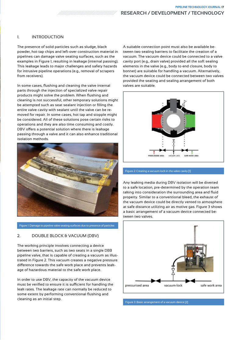
The presence of solid particles such as sludge, black powder, hot-tap chips and left-over construction material in pipelines can damage valve seating surfaces, such as the examples in Figure 1, resulting in leakage (internal passing). This leakage leads to major challenges and safety hazards for intrusive pipeline operations (e.g., removal of scrapers from receivers).
In some cases, flushing and cleaning the valve internal parts through the injection of specialized valve repair products might solve the problem. When flushing and cleaning is not successful, other temporary solutions might be attempted such as seat sealant injection or filling the entire valve cavity with sealant until the valve can be re-moved for repair. In some cases, hot tap and stopple might be considered. All of these solutions pose certain risks to operations and they are also time consuming and costly. DBV offers a potential solution where there is leakage passing through a valve and it can also enhance traditional isolation methods.
2. DOUBLE BLOCK & VACUUM (DBV)
The working principle involves connecting a device between two barriers, such as two seats in a single DBB pipeline valve, that is capable of creating a vacuum as illus-trated in Figure 2. This vacuum creates a negative pressure difference towards the safe work place and prevents leak-age of hazardous material to the safe work place.
In order to use DBV, the capacity of the vacuum device must be verified to ensure it is sufficient for handling the leak rates. The leakage rate can normally be reduced to some extent by performing conventional flushing and cleaning as an initial step.
A suitable connection point must also be available be-tween two sealing barriers to facilitate the creation of a vacuum. The vacuum device could be connected to a valve cavity port (e.g., drain valve) provided all the soft sealing elements in the valve (e.g., body to end closure, body to bonnet) are suitable for handling a vacuum. Alternatively, the vacuum device could be connected between two valves provided the seating and sealing arrangement of both valves are suitable.
Any leaking media during DBV isolation will be diverted to a safe location, pre-determined by the operation team taking into consideration the surrounding area and fluid property. Similar to a conventional bleed, the exhaust of the vacuum device could be directly vented to atmosphere at safe distance utilizing air as motive gas. Figure 3 shows a basic arrangement of a vacuum device connected be-tween two valves.
Figure 1: Damage to pipeline valve seating surfaces due to presence of particles
Figure 2: Creating a vacuum lock in the valve cavity [1]
Figure 3: Basic arrangement of a vacuum device [2]
RESEARCH / DEVELOPMENT / TECHNOLOGYPIPELINE TECHNOLOGY JOURNAL 17

The vacuum device can also be connected to a flare sys-tem with nitrogen as a motive instead of compressed air to avoid the creation of an explosive mixture in the vent pipe. The mixture must be kept outside the flammability zone, such as the example shown in Figure 4, with consideration for the leak rate.
In case of wet gas service, a liquid catcher vessel can be placed between the bleed connection and the vacuum device. For liquid applications, the vacuum device can be equipped with a liquid removal tool consisting of two ves-sels, one atmospherically drained and the other in service with switching over functionality based on operation pref-erence. For liquified gas applications, the vacuum device can be equipped with an evaporator to ensure the liquids are vaporized before reaching the device inlet.
The vacuum device selected went through formal HAZOP and HAZID studies and had PED, CE, EMC and ATEX explosion proof certifications. Class 1 Div. 1 versions are also available. The vacuum device was supplied as part of
a fully integrated small skid providing in-built overpres-sure protection, full automation, allowing monitoring and recording of the bleed section automatically every second without human interaction, fail safe functionality, local visual alarms, local audible alarms, remote wireless online alarm functionality to the safe work area and control room, permitting several pre-alarm functionalities.
3. DBV CATEGORIZATION
Industrial isolation categories for the safe isolation of plant and equipment are shown in Figure 5. While DBV is not included, DBV surpasses the safety level of traditional Double Block and Bleed configurations and can offer en-hancements for process isolation and in cases such as the field trial discussed it can provide a feasible solution.
Figure 4: Flammability diagram showing Air to Nitrogen Safe Mixture [3]
Figure 5: Isolation Categories [4]
Figure 6: Trial location
RESEARCH / DEVELOPMENT / TECHNOLOGY18 PIPELINE TECHNOLOGY JOURNAL

4. FIELD TRIAL
• LOCATION
A 40” class 600 Scraper trap in sweet gas service was selected for testing the usage and performance of the vac-uum device and all of its integrated features, settings and alarms. A photograph of the location is shown in Figure 6. This location was selected as the single API 6D trunnion mounted ball valve isolating the scraper trap had been scheduled for replacement in the next shutdown window due to severe passing which was restricting the pipeline scraping activities. Operations had made several attempts to isolate the trap by flushing, cleaning and inject sealant compounds into the valve with no success. This location was deemed a good opportunity for evaluating the perfor-mance and usage of DBV.
• PRE-TRIAL ASSESSMENT
A pre-trial assessment was conducted to establish the ac-tual leakage rate and the required capacity for the vacuum device. After depressurizing the scraper trap and the valve cavity, the leakage rate was determined by monitoring the rate of pressure build up in the valve cavity and in the scraper trap.
The leakage through the valve was audible and cooling of piping was noticeable indicating significant passing. The rate of pressure increases in the valve cavity and in the scraper, trap is illustrated in Figure 7. The leakage rate past the upstream seat (pipeline side) was calculated to be 150 ft ³ / minute. The downstream seat (scraper trap side) which had a double piston effect configuration had severe damage allowing the pressure in the valve cavity and the scraper trap to equalize in 15 minutes. The pressure con-tinued to increase rapidly and the pressure in the trap was equalized with the pipeline within 120 min.
• TRIAL TEST
The vacuum device as supplied by a specialized third-party company who invented this isolation method was hooked up to both body cavity vent and drain connections via high pressure flexible hoses. Figure 8 shows the vacuum device undergoing hook-up. The outlet of the device was connect-ed to the blow down system.Similar to the pre-trial assessment, the pressure in the valve cavity and in the scraper trap were monitored throughout the trial. The pressure build-up in the valve cav-ity and in the scraper trap is illustrated in Figure 9.
Figure 7: Pressure Reading in the Valve Cavity and Trap
Figure 8: Hook-up of the vacuum device to the valve body cavity connections
Figure 9: Pressure build up with the vacuum device in operation
RESEARCH / DEVELOPMENT / TECHNOLOGYPIPELINE TECHNOLOGY JOURNAL 19

Immediately after starting the vacuum device, a pressure drop was noticed. The pressure in the trap remained at 0 psi throughout the trial. The valve cavity pressure could not reach sub-atmospheric conditions due to resistance in the vent outlet and the 1 inch bleed connections.
After approximately 55 minutes, grease was injected to the upstream seat through the injection fittings and the pressure in the valve body cavity started dropping once the effective seating was established a vacuum was achieved in approximately 10 minutes. After that, the pressure start-ed to drop further until levelling out at -167 mbarg
The trial was concluded after three hours of continuous operation. Zero pressure was maintained in the scrapper trap for the duration of the test and the device successfully monitored the leakage rate continuously every second.
As part of the trial scope, the safety features of the vacuum device were tested by simulating the following potential risks:
• increase in the leakage rate.• blockage in the suction.• loss of motive gas supply.
The vacuum device responded in accordance with a series of pre-determined visual and audible alarms. In each of the three scenarios, the response of the DBV device was found to be satisfactory. Overall, the skid mounted design provided a relatively straight forward and quick hook-up procedure compared to other isolation methods.
5. CONCLUSION
The evaluation and trial of DBV technology confirmed the capability of the device to create a vacuum lock between the two seats of a single DBB valve allowing the isolation of the trap and maintaining the isolation for the entire du-ration of the trial which was not possible using traditional isolation methods.
The response of the vacuum device to different risks includ-ing increase in the leakage rate, blockage in the suction and loss of motive gas supply were simulated, examined and found to be satisfactory during the trial.
The vacuum lock prevented leakage of hazardous mate-rial to the safe work place and the fully automated design provided continuous isolation proving and monitoring with fail-safe functionality.
ACKNOWLEDGMENTS
The authors would like to acknowledge Saudi Aramco for support in presenting this paper and Valvetight for provid-ing their vacuum device and participating in the trial.
References
1. Working behind leaking valves: Dilemma Between Safety and Operational Targets (Valve World Magazine November 2018)
2. DBB-Saver by Valvetight (https://valvetight.com)3. Chemical Process Safety: Fundamentals with Applications, Prentice Hall (2002)4. HSG253 the Safe Isolation of Plant and Equipment (second edition, published 2006)
Authors
Martin F. Meehan
Saudi Aramco
Engineering Specialist
Bader M. Al-Jarallah
Saudi Aramco
Engineering Consultant
Hassan A. AlSalloum
Saudi Aramco
Valve Engineer
RESEARCH / DEVELOPMENT / TECHNOLOGY20 PIPELINE TECHNOLOGY JOURNAL

TECHNICAL SESSIONS PANEL DISCUSSIONS NETWORKINGEXHIBITION
17TH PIPELINE TECHNOLOGY CONFERENCE 7-10 MARCH 2022, BERLIN, GERMANY (+ PTC REMOTE)
Meet the international Pipeline Community in Berlin
CALL FOR PAPERS OPEN UNTIL 30 SEPTEMBER 2021
10 % EXHIBITION EARLY BIRD UNTIL 30 NOVEMBER 2021
www.pipeline-conference.com
SUPPORTERS
SPONSORS
WITH

Diana Rennkamp, Michael Lubberger > Herrenknecht AG
Abstract
For the gas supply in Europe, a reliable pipeline network has the highest priority. Besides the construction of the main supply routes, the fast and safe installation of the regional country-specific distribution networks play a key role.
Different points of view of all involved parties have to be considered when it comes to the planning of routes and the evaluation of potential installation technologies. Due to a rising public attention paid to environmental issues and landowners´ concerns, the impact of pipeline construction on the surroundings has to be reduced to a mini-mum. While a large proportion of cross-country pipeline installations are still executed by conventional open-trench methods, trenchless technologies are considered for sensitive crossings or pipeline landfalls. Pipe Express®, as a semi-trenchless method, presents an alternative where open-cut methods would cause high efforts, reducing re-quired right of way (ROW) by 70% with less impact on surroundings.
For the crossings of waterways or protected areas, trenchless solutions are usually considered. Along the TAP route for example, various Direct Pipe® and HDD crossings have been executed. The TAP landfall in Southern Italy (Adri-atic Sea) was designed as a pipe jacked casing tunnel, similar to the TurkStream connections in Anapa (Black Sea), Russia.
Proven in more than 160 crossings worldwide, the Direct Pipe® technology has been used in Bulgaria and in Serbia, setting Europe´s distance record of 1,409 meters in 2019 in Serbia. This paper will present the latest trenchless and semi-trenchless pipeline installations along Europe´s major pipeline routes, including examples for the offshore-on-shore connection of LNG terminals and gas fields.
Trenchless pipeline installations in European key projects

1. INTRODUCTION
Even though renewable energies are being significantly ex-panded throughout Europe as part of the energy transition, gas still plays a major role as a fossil fuel, especially as a bridging technology in the phase-out of nuclear energy and lignite. As their own reserves run out, European countries will be increasingly dependent on gas imports in the future to ensure the production of heat and electricity for private households and energy for the industry. Connections to new gas supply routes, such as through the Baltic Sea or to offshore gas deposits as in Azerbaijan via the TAP pipeline, are expected to provide security of supply and flexibility to the European gas market. New LNG terminals will deliver additional gas to Europe’s coasts.
In order to create a reliable and sustainable network for the upcoming decades, existing pipelines have to be expanded and new pipeline capacities have to be built. Innovative construction methods are needed to fulfill the project re-quirements, to match the time schedule and to comply with environmental regulations and concerns.
Open-trench construction methods are commonly the most efficient and fastest pipeline construction methods for cross-country pipeline installations. But in most pipeline projects it is not possible to trench the whole pipeline route.
Hence, it will be necessary to cross existing surface and sub-surface obstacles such as roads, railways, underground installations and waterways along the pipeline route.
Different trenchless pipeline construction methods are available to cross obstacles on the route in a safe, effec-tive and environmentally acceptable manner. Innovative technical concepts enable these technologies to be used also in the construction of outfall structures and pipeline landfalls. Whereas in conventional HDD or Direct Pipe® the product pipeline is directly installed, methods from the tun-nelling industry provide pipe jacked or segmentally lined casing tunnels in which the pipeline is inserted in a second step. In order to assure Europe´s gas supply for the next decades, the whole range of technologies can be applied along the main pipeline routes and national distribution networks.
2. CASING TUNNELS IN SENSITIVE AREAS
In sensitive areas such as for coastal sections or under rivers, safety plays a particularly important role during installation and subsequent pipeline operation. The con-struction of an accessible casing tunnel, into which the pipeline is pulled or pushed in at a later stage, is often the
SEMITRENCHLESS
TRENCHLESS
Pipe Express® Auger Boring HDD Direct Pipe® E-Power Pipe® Casing tunnel
Pipe Jacking Segment Lining
Installation product pipe
one-step one-step / multi-stage
multi-stage one-step multi-stage direct / indirect
indirect
Material product pipe
pressure- resistant
all all pressure- resistant
all all all
Diameter product pipe
30”– 60” 4”– 56” 10”– 60” 24”– 60” 10”– 28” 250 – 4,000 mm tunnel ID
> 2,300 mm tunnel ID
Max. installation length
2,000 m 100 m 5,000 m 2,000 m 1,000 m 2,500 m 10,000 m
Min. installation depth
1 m 1.5 × pipe (OD)
10 – 15 × pipe (OD)
3 × pipe (OD)
1.5 m 2 – 3 × tunnel (OD)
2 – 3 × tunnel (OD)
Geology all rock < 15 MPa
all rock < 30 MPa
stable all rock < 150 MPa
all rock < 30 MPa (temp. 150 MPa)
all all
Overview and comparison of pipeline installation methods
The information in this table is intended as an initial guideline; the parameters may vary depending on the project.
Table 1: Overview and comparison of pipeline installation methods
RESEARCH / DEVELOPMENT / TECHNOLOGYPIPELINE TECHNOLOGY JOURNAL 23

safest solution for pipeline landfalls and river crossings. In this way, the impact on the environment can be minimized. Emissions and vibrations caused by conventional pipeline installation are significantly reduced. Existing pipeline net-works can be maintained. Laying operations are largely in-dependent of external conditions such as weather, storms, high tides or sediment transport. Underground installation extends the life cycle of the pipeline, the pipeline remains protected underground from damage by ships or sabotage, with lower subsidence risk and higher earthquake resis-tance.
2.1. PIPELINE LANDFALLS IN CASING TUNNEL
Pipeline landfalls are often installed in casing tunnels, which can be safely constructed by pipe jacking technolo-gy from the coast into the open sea, where the tunnelling machine is recovered from the seabed.
Due to the complex ground conditions in a highly seis-mic region, the two landfalls of the Turkstream Pipeline in Anapa, Russia, were designed as microtunnels to host the 32” steel gas pipelines. Two Herrenknecht AVN 2000 remote-controlled slurry machines for pipe jacking (outer pipe diameter 2,450 mm) were used for the excavation of the 1,440 m and 1,470 m long casing tunnels. Due to the topography of the Caucasus Mountains near the coast, the tunnel into the Black Sea had to pass under a partly frac-tured rock face with up to 163 m overburden starting from the launch shaft. Down to the target point in 30 meters below sea level, a partly very steep gradient of 11.5% and an altitude difference of 80 meters had to be overcome. The tunnelling machine, the slurry system and the pumps were designed specifically for the project for 8 bar pressure.
Due to the very long drive length, a total of 10 intermediate jacking stations were installed to provide sufficient jacking force. A volume-controlled bentonite lubrication system was successfully used to keep jacking forces as low as possible. Through a highly variable and partially fractured rock mass with anticipated groundwater, the average per-formance rate was 15-21 m/day. Both landfall microtunnels were completed in April 2017.
The pipe jacking method is also repeatedly used for land-falls of gas pipelines on the coasts of the Baltic Sea for the safe construction of casing tunnels. In most cases, the geological boundary conditions and safety aspects are the decisive points in the selection of this construction method in coastal areas. Environmental aspects are often another important criterion, as for example on the Southern coast of Italy, where a 1,566 meter long microtunnel with an outer diameter of 3 meter was constructed in 2018 to land the TAP pipeline.
2.2. LONG RIVER CROSSING IN CASING TUNNEL
In Great Britain, a new gas pipeline under River Humber replaces the existing Pipeline 9 which was laid in a trench just below the riverbed, exposed to shifting tides. The pipeline replacement project consists of a segment lining tunnel which will house a 42” gas pipeline to connect the national network in Goxhill in North Lincolnshire to Paull in East Yorkshire, where the gas comes onshore. The 4,862 meter long tunnel runs with 10 meter coverage below the Humber River bed. With a slope of up to 4% in both riv-erbank areas, the tunnel alignment is situated in chalk, alluvium and glacial deposits. The main challenge in tunnel construction was the length of the tunnel section without intermediate shaft, with impact on detailed planning and design for working safety and logistics in this relatively small inner tunnel diameter of approximately 3,650 mm. A Mixshield TBM with a shield outer diameter of approxi-mately 4,340 mm was used for the project. Logistics have been handled by a Multi Service Vehicle (MSV), not by a rail-bound locomotive, which was a premiere in England for this diameter range. A sophisticated safety concept was implemented to assure additional working safety at all times during the tunnelling progress.
2.3 PIPELINE INSTALLATION WITH PIPE THRUSTER
Several solutions are available for inserting a pipeline into a completed casing tunnel. One possibility is pipeline in-sertion by means of a Pipe Thruster, a thrust unit originally developed for HDD, which is installed in the launch shaft to push the prefabricated pipeline into the casing tunnel.
This procedure was also used for the River Humber Cross-ing in England described above, as for safety reasons welding was not permitted in the tunnel to join the 12-me-ter-long concrete-sheathed pipes. After completion of
Figure 1: View into completed segment lining tunnel
RESEARCH / DEVELOPMENT / TECHNOLOGY24 PIPELINE TECHNOLOGY JOURNAL

the tunnelling work, all tunnel installations were removed from the tunnel and two Herrenknecht Pipe Thrusters with maximum push forces of 500 and 750 tons respectively were erected in the launch shaft. A total of 8 pipe sections up to 624 m long were welded together in the area of the launch shaft and pushed into the flooded tunnel with the help of the Pipe Thrusters. With a length of almost 5 km, this is a world record in the Guinness Book of Records for this special type of pipeline insertion.
3. DIRECT PIPELINE INSTAL-LATION WITH DIRECT PIPE®
The Direct Pipe® technology for the trenchless installation of prefabricated steel pipelines has become established worldwide over the last 15 years. It combines the microtun-neling and the Pipe Thruster technologies, bringing their advantages together to enable trenchless installation of pipelines in difficult ground conditions while reducing the risks. Direct Pipe® allows excavation of the borehole and simultaneous trenchless installation of a prefabricated and tested pipeline in a single continuous step. Typically, Direct Pipe® is used to safely cross rivers or other obstacles.
As a result of further technical development and growing popularity among clients and construction companies, the range of applications for Direct Pipe® has steadily been expanded in recent years. Today, Direct Pipe® is also in-creasingly used for pipeline landfalls. In this case, the AVN tunneling system can be decoupled from the pipeline at its target point to be recovered from the seabed. At the same time, the technology has also evolved in terms of installa-tion length and diameter. In New Zealand, a world record was achieved in 2020 with the installation of a 2,021-me-ter-long wastewater pipeline into the open sea. New devel-opments in machine technology today make Direct Pipe® possible even in small diameters from 24” upwards.
3.1. DANUBE RIVER CROSSING, SERBIA
A gas pipeline system of 402 km length and a diameter of 48” will connect Bulgaria and Hungary throughout the Serbian territory. On its way, the Transmission Gas Pipeline (Interconnector) had to cross several obstacles. About 10 of the larger crossings between 500 and 1000 m length were undertaken using the HDD technology.
In Kovin, 50 km east of Belgrad, the Danube River had to be crossed on a length of 1,409 m. As HDD appeared too risky to apply in the highly permeable soil, the crossing was originally designed as a microtunnel. Due to the tight time schedule, the installation of the concrete pipe casing and the subsequent insertion of the steel pipeline was con-sidered as a too time-consuming procedure making two single steps necessary. Finally, Direct Pipe® was chosen as the preferred installation method, as excavation and instal-lation of the prefabricated steel pipeline are taking place in one single step, providing safe excavation and continuous support of tunnel face and borehole at the same time.
With two Pipe Thrusters of available maximum 750 ton push force each, all 4 pipeline sections were successful-ly installed to complete this 1,409 m long river crossing. Whereas the Direct Pipe® distance world record has been set in New Zealand in 2020 at 2,021 m length, the Danube crossing in Serbia presents the current European distance record.
The drive through mixed formations of sand, silt and gravel was completed end of November 2019 with a best daily performance of 120.8 m (24h) and a maximum weekly progress of 407.5 m.
Figure 2: Pipe Thruster clamping the 42” pipeline for pushing into the segment lining tunnel
Figure 3: Direct Pipe jobsite installation at Danube River with two Pipe Thrust-ers HK750PT
RESEARCH / DEVELOPMENT / TECHNOLOGYPIPELINE TECHNOLOGY JOURNAL 25

3.2. ALIAKMONAS RIVER CROSSING, GREECE
The TAP (Trans Adriatic Pipeline) pipeline is connected to the TANAP (Trans-Anatolian Natural Gas Pipeline) pipe-line in Tipoi, close to the Turkish-Greek border. Along the further TAP route through Greece and Albania various HDD crossings have been undertaken. For two 48” crossings of the Aliakmonas River in Kastoria, Northwestern Greece, close to the Albanian border, HDD was also considered in the early design stage of the project. But geotechnical investigation indicated a high content of gravel exceeding 70% share on some of the sections with layers of hard rock and loam. Due to these conditions, Direct Pipe® turned out to be the better suited technology. A special cutting wheel of the AVN 1000 Direct Pipe® machine was designed to face the geological conditions on the project. On the first crossing of 540 m length, one single pipeline section was installed. The pipeline for the second crossing of 612 m length was divided into 3 pipe sections.
4. SHORT PIPELINE CROSSINGS
4.1. SHORT RIVER, RAILWAY & ROAD CROSSINGS WITH STEEL PIPE JACKING
On the Southern section of EUGAL (Lot 13 & 14), close to the Czech border, an AVN1200TB microtunnelling machine was used to cross five of the smaller obstacles, e.g. Highway BAB A4, the Bobritzsch River and a street with an important sewer line. Individual drilling lengths between 18 m and 96 m had to be overcome.
The 18m long 56” gas pipes with a wall thickness of 22 mm were directly pushed behind the AVN machine into the borehole with the aid of a long jacking frame. This proce-dure necessitates, that after each installed pipe a new pipe has to be lowered into the shaft, welded, tested and coated. Because the alignment of these kind of trenchless cross-ings are normally designed as short as possible, the launch shaft has to be nearly as deep as the traversed obstacle. In comparison to the Direct Pipe® technology, where the Pipe Thruster is setup near the surface and generally longer pipe sections are continuously installed, this type of steel product pipe jacking method requires the jacking frame to be setup in a very long launch shaft with lengths of minimum 20m. On the five described crossings for the Eugal shafts of up to 14m depth had to be built.
Due to the project conditions, two of the crossings had to be executed following an upward inclination of 13-14%. A hydraulic pipe brake was mounted in the launch shaft to hold the installed pipeline in its position during the transi-tion of the jacking frame position and during the coupling and welding of the next pipe section. A further challenge on four of the crossings was the compressive strength of the Erzgebirge (Ore Mountains) rock with up to 266 MPa paired with very high abrasivity. However, the extremely strong main bearing and main drive of the AVN-machine in combination with the assembled rock cutting head were able to achieve acceptable performances even under these demanding circumstances. Drilling speeds of around 30-70 mm/min in the softer rock (around 30 MPa) and of approx. 10-40 mm/min in the very strong rocks (160-266 MPa) could be reached. With regard to the experiences gained from the construction of the OPAL pipeline ten years ago, a considerable wear of
Figure 4.Overview on Direct Pipe® jobsite in Greece with Pipe Thruster HK500PT installed in launch shaft [Source: Chrobok PPI]
RESEARCH / DEVELOPMENT / TECHNOLOGY26 PIPELINE TECHNOLOGY JOURNAL

the cutting tools was expected. Therefore, the machine was regularly equipped with new cutting tools.
4.2. SHORT CROSSINGS WITH AUGER BORING
The most cost-effective method for short crossings of roads or railroad tracks is the auger boring method, thanks to its very fast installation and simple operation. The steel pipe can be installed directly in the ground even with small overburden. The dry discharge of the excavated soil eliminates the need for the relatively costly separation measures required by slurry machines. Although the scope of auger boring technology is limited to relatively short crossings of up to 100 meters in length, the method is a competitive alternative under certain conditions. The geo-logical application possibilities, also in non-displaceable soils and rock, could be significantly extended by technical advancements such as the so-called front steering.
The expansion of the South Caucasus Pipeline (SCPX) is part of the Shah Deniz Full Field Development project. This expansion involves the laying of a new pipeline across Azerbaijan and the construction of two new compressor stations in Georgia.
Guided Auger Boring is very often used for short pipeline crossings such as under traffic routes. As part of the SCPX, solely in Azerbaijan more than 100 of such underground crossings with maximum lengths of up to 95 m have been
executed with steel pipe jacking. The project involved crossing roads and highways, rail lines, the BTC pipeline (Baku-Tibilisi-Ceyhan pipeline) and the WREP pipeline (Western Route Export pipeline), irrigation channels and local oil and gas pipelines. The overburden was between 1.5 m and 6 m, the launch shafts had depths of 3 m to 7.5 m, The diameter of the pipeline was 48”. The geology mainly consisted of medium-dense to dense clay with partly high groundwater levels, which, however, was unproblematic owing to the cohesive soil.
Figure 5: Overview of the Southern Corridor gas pipeline projects [Source: Herrenknecht AG]
Figure 6: Installation of final product pipe [Source: Bohrtec GmbH]
RESEARCH / DEVELOPMENT / TECHNOLOGYPIPELINE TECHNOLOGY JOURNAL 27
The contractor responsible for the steel pipe jacking and decided in consultation with Herrenknecht/Bohrtec to use two long frame machines of the types BM 800 L and BM 800 LS, which only differ in their torque. Due to the toler-ances of max. 1% specified by the client and because of the displaceable soil, Guided Pilot Pipe Jacking with intermedi-ate reaming was chosen as the method variant.
Since jacking the product pipes directly with the augers inside was not permitted, initially temporary steel pipes with a diameter of 1245 mm (49”) were jacked. The inter-mediate reaming diameter was 609 mm. After completion
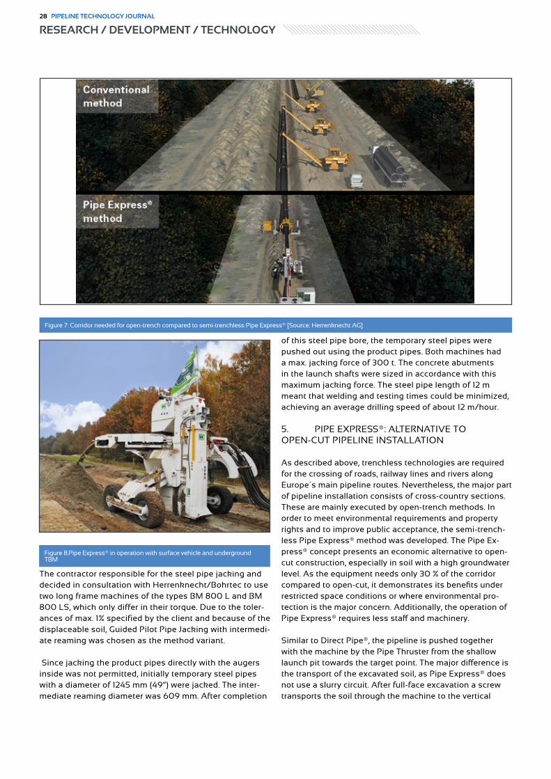
of this steel pipe bore, the temporary steel pipes were pushed out using the product pipes. Both machines had a max. jacking force of 300 t. The concrete abutments in the launch shafts were sized in accordance with this maximum jacking force. The steel pipe length of 12 m meant that welding and testing times could be minimized, achieving an average drilling speed of about 12 m/hour.
5. PIPE EXPRESS®: ALTERNATIVE TO OPEN-CUT PIPELINE INSTALLATION
As described above, trenchless technologies are required for the crossing of roads, railway lines and rivers along Europe´s main pipeline routes. Nevertheless, the major part of pipeline installation consists of cross-country sections. These are mainly executed by open-trench methods. In order to meet environmental requirements and property rights and to improve public acceptance, the semi-trench-less Pipe Express® method was developed. The Pipe Ex-press® concept presents an economic alternative to open-cut construction, especially in soil with a high groundwater level. As the equipment needs only 30 % of the corridor compared to open-cut, it demonstrates its benefits under restricted space conditions or where environmental pro-tection is the major concern. Additionally, the operation of Pipe Express® requires less staff and machinery.
Similar to Direct Pipe®, the pipeline is pushed together with the machine by the Pipe Thruster from the shallow launch pit towards the target point. The major difference is the transport of the excavated soil, as Pipe Express® does not use a slurry circuit. After full-face excavation a screw transports the soil through the machine to the vertical
Figure 7: Corridor needed for open-trench compared to semi-trenchless Pipe Express® [Source: Herrenknecht AG]
Figure 8.Pipe Express® in operation with surface vehicle and underground TBM
RESEARCH / DEVELOPMENT / TECHNOLOGY28 PIPELINE TECHNOLOGY JOURNAL

trenching unit (30 to 40 cm width) to the surface. Up to 2,000 m long pipelines with a diameter of 760 – 1,500 mm (30” - 60”) can be laid quickly and cost-efficiently. Pipe Express® can also be used for the construction of pipeline landfalls. Therefore, the machine is pushed together with the pipeline into the water and following the seabed level. The advantage of the lower space requirement and the use in sensitive environments with high groundwater levels are decisive arguments. Pipe Express® proves to be particularly advantageous if it is already taken into account in the early approval planning phase when looking for a possibly short pipeline route. Since much narrower route corridors can be considered when using Pipe Express®, otherwise neces-sary bypasses can be saved and thus shorter routes can be planned.
6. OUTLOOK
The planning and approval process for new gas pipelines requires the use of innovative trenchless technologies. Under the given project conditions, the methods under consideration must be examined in terms of feasibility and economic viability. New areas of focus in the con-struction industry will be the environmental footprint and impact of construction projects. Environmentally friendly technologies that are efficient and provide a high degree of economic planning security will have to be used in the construction of sustainable pipeline networks in order to implement the visions of tomorrow’s energy supply.
Authors
Michael Lubberger
Herrenknecht AG
Head of Business Division
Pipeline
Lubberger.Michael@
herrenknecht.de
Diana Rennkamp
Herrenknecht AG
Sales Engineer Pipeline
Rennkamp.Diana@herrenknecht.
de
PIPELINE INSTALLATION IN ONE STEP
DIRECT PIPE®
With the unique Direct Pipe® technology, Herrenknecht has opened up new possibilities for installing pipelines in every geology in one single step. This facilitates speedy and highly economical installation of pipelines up to 2,021 meters. Impressively proven in 170 crossings around the globe. www.herrenknecht.com/directpipe/
Client: Watercare
Customer: McConnell Dowell
21-08-25_002_ID21182_eAz_DirectPipe_Pipeline Technology Journal_210x148_RZcd.indd 121-08-25_002_ID21182_eAz_DirectPipe_Pipeline Technology Journal_210x148_RZcd.indd 1 26.08.21 4:15 PM26.08.21 4:15 PM
RESEARCH / DEVELOPMENT / TECHNOLOGYPIPELINE TECHNOLOGY JOURNAL 29

Klaus Robl; Alper Taşdemir, Ahmet Şaşmaz > ILF Consulting Engineers Austria; TANAP
Abstract
The TANAP route runs 92 km through one of the world´s largest gypsum karst terrains, covering an area of 2140km² (Günay 2002; Doğan & Yeşilyurt 2019) located in the Turkish Province of Sivas. A fantastic place for the geologist but a big challenge for the routing and construction of a pipeline.
Based on the morphology a karst classification, comprising of 5 karst types, was set up. The development of a genetic karst model enabled the assignment of specific hazards to each of the identified karst types. These hazards comprise of collapse dolines, subsidence sinkholes, internal erosion and pinnacled bedrock. Each karst type required a specific risk mitigation depending on type and severity of the hazard, to be considered either by routing or by ap-plying technical measures.
Construction finally proofed that the karst model was correct. This was also underlined by the discovery of a large cave on the right of way during grading works within one of two short route sections with a predicted high risk of large cavities. Detailed ground investigations were necessary to assess the irregular shape of the cave and to move the alignment to safe ground.
Experience from BTC and Nabucco Projects which also cross this gypsum karst area on different routes were highly beneficial for the successful completion of the task.
The Sivas Gypsum Karst - Implications for Routing, Construction and Operation of the Trans Anatolian Natural Gas Pipeline

1. INTRODUCTION
TANAP aims to convey natural gas from the Caspian region via Turkey to Europe. It is part of the Southern Gas Corridor, which consists of three main elements: the South Caucasus Pipeline (SCPX) running form Azerbaijan’s giant Shah Deniz gas field through Georgia to Turkey, TANAP which traverses Turkey from East to West between Posof at the Turkish-Georgian border and Ipsala at the Turk-ish-Greek border and the Trans-Adriatic Pipeline (TAP) starting from the Greece/Turkey border, passing through Albania and being tied to Italy through the Adriatic Sea.
The pipeline has a length of 1811 km and crosses various forms of landscapes from coastal plains to high altitude mountain ranges, climbing to an altitude of 2,750 m above sea level. The pipe diameter is 56” for the first 1338 km and 48” for the remaining 455 km up to the Greek border. The Sea of Marmara is being crossed North of the Dardanelles Strait by 2x36” pipes each having a length of 18 km. In its final extension, the pipeline system will comprise of 7 compressor stations and produce 31 bcm/a gas throughput with a design pressure of 95.5 barg.
The various landscapes encountered along the pipeline route as well as the geotectonic position of Turkey at the boundary between the converging Eurasian and African Plates and its geological history make this country almost
unique in terms of type and number of terrain and ground related geohazards, including landslides, active faults, seis-micity, liquefaction, lateral spreading, karst and sinkholes, soil erosion, flooding, and fluvial erosion.
This paper gives an overview over the karst types encoun-tered along the pipeline route between the town of and focusses on the challenges of routing and construction of TANAP in the Sivas gypsum karst, one of the world´s larg-est gypsum karst terrains.
2. GEOLOGIC SETTING
The Sivas basin developed after the closure of the North Tethys Ocean in Upper Cretaceous to Lower Tertiary ages (Yılmaz & Yılmaz 2006). After the sedimentation of flysch like deposits in the Palaeocene and Eocene further crustal shortening resulted in uplift and the deposition of conti-nental strata and massive gypsum which was deposited in a sabkha type environment (Hafik Formation) during the Oligocene (Ciner et al. 2002). The gypsum deposits reach a thickness of up to 500 m (Doĝan & Yeşilyurt 2004). A number of large salt springs and diapiritic structures indicate significant salt bodies at depth. The gypsum strata are overlain by Miocene marine and Pliocene continental formations.
Figure 1: Overview of the TANAP route. The section where TANAP runs through the gypsum karst is marked by the blue rectangle
RESEARCH / DEVELOPMENT / TECHNOLOGYPIPELINE TECHNOLOGY JOURNAL 31

At present much of the gypsum outcrop is bare rock, usu-ally weathered and fractured to a depth of several meters while large areas are covered by plastic residual clays which have been left by surface dissolution of the impure gypsum.
3. GENETIC KARST MODEL
The term karst describes landforms derived by the dissolu-tion of soluble rocks such as limestone, dolomite, gypsum or rocksalt. Karst terrains typically have an underground drainage system. Due to the high solubility in water the karst evolution in gypsum is, unlike limestone karst, a very dynamic process.
The Sivas gypsum karst is exposed on a 280 km long and up to 55 km wide ENE-WSW trending stretch (Doĝan & Yeşilyurt 2020). Three major rivers, Kızılırmak and its tributaries Acısu and Acıçay drain the area. They act as the receiving streams for all karst groundwater of the region and thus set the base level for karstification processes. The evolution of the Sivas gypsum karst is inextricably linked with the spatio-temporal development of these rivers. Un-derstanding the geologic history which led to the present karst topography proofed to be crucial for assessing the karst risks.
Karst formation started after the erosion of the Miocene cover sediments with the exposure of the gypsum strata.
Through fissures and fractures surface water made its way underground forming a large number of solution dolines on the surface and phreatic caves at the groundwater level. Thousands of solution dolines, separated by a polygonal net of low interfluve ridges developed on the gypsum plat-forms (polygonal karst).
The Proto - Kızılırmak and its tributaries which had their sources outside the karst terrain went underground as soon as they reached the gypsum. They were able to dis-solve large cave chambers in massive gypsum, especially if the caves were completely water filled.
Where cave chambers exceeded a certain size and where the overburden was limited, collapse dolines formed. By the time these collapse structures expanded and eventual-ly coalesced with nearby collapse dolines due to continued dissolution, undercutting and a long sequence of progres-sive breakdown failures.
The next stage of karst evolution is represented by the formation of poljes either due to expanding and coalescing collapse dolines or long lasting dissolution processes at the karst margins. Poljes can grow to huge landforms, fre-quently several kilometres wide. Often they contain lakes which are mostly fed by underground streams. It has to be assumed that Proto - Kızılırmak was flowing through a series of poljes which were separated by gypsum plateaus but hydrologically connected by cave systems.
Figure 2: Large river cave in the Sivas Gypsum karst
RESEARCH / DEVELOPMENT / TECHNOLOGY32 PIPELINE TECHNOLOGY JOURNAL

Continued dissolution along the active parts of these cave systems led to the last stage in the karstic surface lower-ing which is represented by alluviated basins hosting the current course of Kızılırmak.
Within the project area karst evolution did not take place simultaneously and at the same pace so that today all stages of karstification are present within short distance.
Based on this genetic model and the present day karst morphology a karst classification could be created which enabled the assignment of specific hazards to each of the identified karst types.
4. KARST FEATURES AND HAZARDS
4.1 GENERAL
The main geohazard in karst is represented by sinkholes, also known as dolines. The hazard is related to the devel-opment of new sinkholes which can form suddenly without any warning signs anywhere within karst terrain but also to ground movement in existing sinkholes. Pinnacled rock-head beneath the pipeline, transfer of bedding / padding material into open karstic voids and groundwater with high concentrations of sulfate and chloride are further hazards to be considered in gypsum karst.
The Karst hazard is very often not recognized or under-estimated. The USGS (United States Geological Survey) estimates that sinkhole damages in the USA over the last 15 years cost on average at least $300 million per year. Much of these damages could have been avoided if a prop-er karst assessment had been carried out and mitigation measures taken.
4.2 SINKHOLES
Within the Sivas gypsum karst three types of sinkholes or dolines can be distinguished.
• SOLUTION DOLINES Solution dolines form by the dissolution of gypsum around the drainage outlet, a relatively slow process which typically lasts over several tens of thousands of years. The doline floors are frequently covered by cohesive residual soils. Commonly surface water is discharged into narrow karst fissures. Even in very old and large solution dolines the width of these fissures rarely exceeds half a meter. Thus the hazard to the pipeline is considered to be low.
• COLLAPSE DOLINES Collapse dolines occur when large, near surface cave chambers get instable and collapse. As opposed to limestone karst, caves in gypsum usually form smaller chambers. Nevertheless there are examples of more than 40 metres wide cavities in gypsum. Field map-ping showed that initial collapse dolines may be up to 20m across and further widened by subsequent phases of progressive wall collapse.
Figure 4: TANAP is passing on the upper side of a large solution doline
Figure 3: Main types of sinkholes found in the Sivas gypsum karst (Waltham 2013)
RESEARCH / DEVELOPMENT / TECHNOLOGYPIPELINE TECHNOLOGY JOURNAL 33
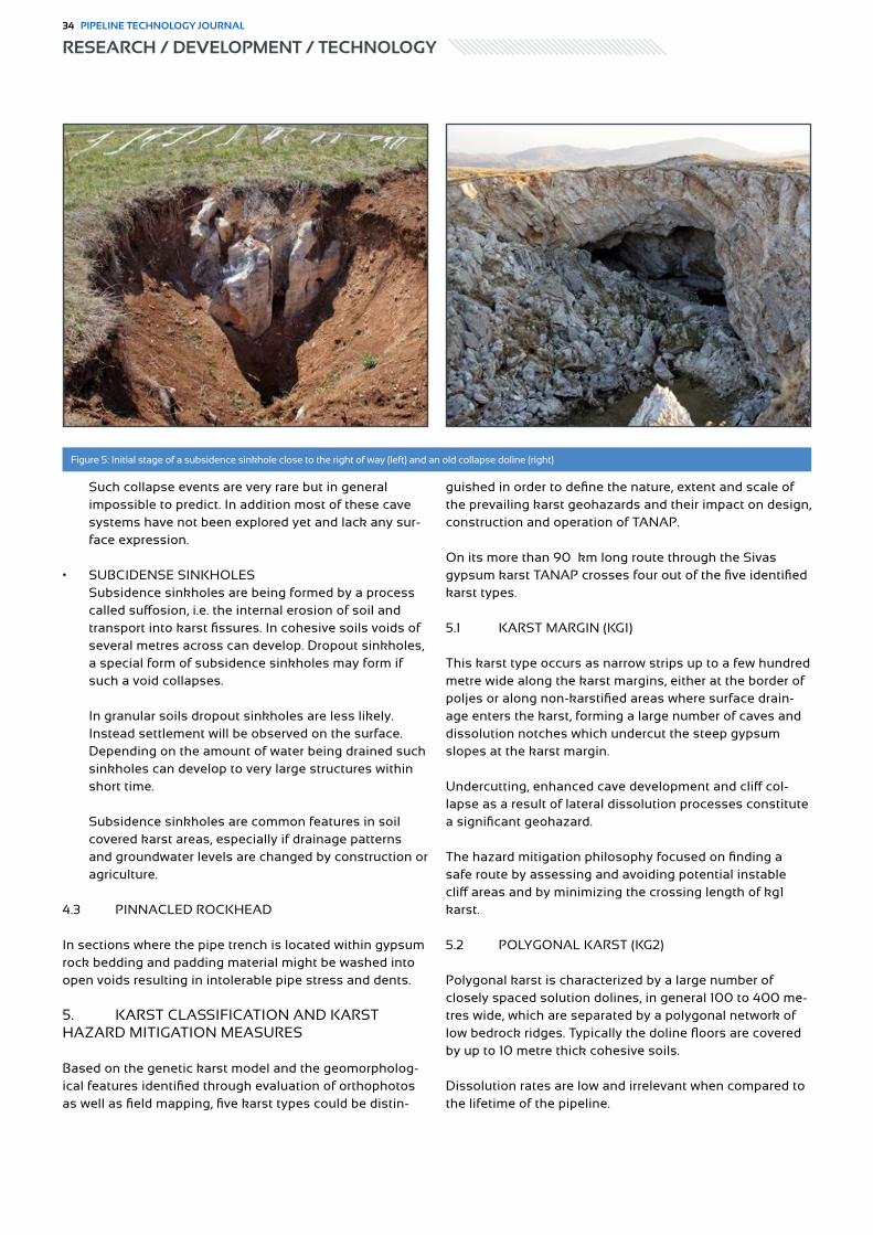
Such collapse events are very rare but in general impossible to predict. In addition most of these cave systems have not been explored yet and lack any sur-face expression.
• SUBCIDENSE SINKHOLES Subsidence sinkholes are being formed by a process called suffosion, i.e. the internal erosion of soil and transport into karst fissures. In cohesive soils voids of several metres across can develop. Dropout sinkholes, a special form of subsidence sinkholes may form if such a void collapses. In granular soils dropout sinkholes are less likely. Instead settlement will be observed on the surface. Depending on the amount of water being drained such sinkholes can develop to very large structures within short time. Subsidence sinkholes are common features in soil covered karst areas, especially if drainage patterns and groundwater levels are changed by construction or agriculture.
4.3 PINNACLED ROCKHEAD
In sections where the pipe trench is located within gypsum rock bedding and padding material might be washed into open voids resulting in intolerable pipe stress and dents.
5. KARST CLASSIFICATION AND KARST HAZARD MITIGATION MEASURES
Based on the genetic karst model and the geomorpholog-ical features identified through evaluation of orthophotos as well as field mapping, five karst types could be distin-
guished in order to define the nature, extent and scale of the prevailing karst geohazards and their impact on design, construction and operation of TANAP.
On its more than 90 km long route through the Sivas gypsum karst TANAP crosses four out of the five identified karst types.
5.1 KARST MARGIN (KG1)
This karst type occurs as narrow strips up to a few hundred metre wide along the karst margins, either at the border of poljes or along non-karstified areas where surface drain-age enters the karst, forming a large number of caves and dissolution notches which undercut the steep gypsum slopes at the karst margin.
Undercutting, enhanced cave development and cliff col-lapse as a result of lateral dissolution processes constitute a significant geohazard.
The hazard mitigation philosophy focused on finding a safe route by assessing and avoiding potential instable cliff areas and by minimizing the crossing length of kg1 karst.
5.2 POLYGONAL KARST (KG2)
Polygonal karst is characterized by a large number of closely spaced solution dolines, in general 100 to 400 me-tres wide, which are separated by a polygonal network of low bedrock ridges. Typically the doline floors are covered by up to 10 metre thick cohesive soils.
Dissolution rates are low and irrelevant when compared to the lifetime of the pipeline.
Figure 5: Initial stage of a subsidence sinkhole close to the right of way (left) and an old collapse doline (right)
RESEARCH / DEVELOPMENT / TECHNOLOGY34 PIPELINE TECHNOLOGY JOURNAL

Table 1: Karst types along the TANAP route
Figure 6: Large collapsed cave at karst margin bordered by a polje
RESEARCH / DEVELOPMENT / TECHNOLOGYPIPELINE TECHNOLOGY JOURNAL 35

Settlement within the doline soils due to suffosion and for-mation of new subsidence sinkholes constitute the main geohazards within the polygonal karst. Also pinnacled rockhead has to be accounted for and, as in all other karst types where the pipe trench was excavated in gypsum rock, geotextile was used to prevent the bedding / padding from being washed into karstic voids.
The pipeline was preferably routed along the ridges be-tween the dolines or on the doline flanks.
Where doline floors had to be crossed measures to control the drainage were implemented to mitigate these hazards.
Mitigation measures comprised of trench breakers to prevent water from concentrating in the trench and flowing down the internal doline slopes where it could accelerate suffosion processes and the installation of impermeable material at the trench bottom which should impede exces-sive water infiltration and reduce suffosion significantly.
New subsidence sinkholes within the doline soils are typi-cally only a few metres wide at their initial stage and could be safely spanned by the pipeline.
The danger coming from pinnacled rockhead was mitigat-ed by increasing the bedding thickness.
5.3 PLATEAU KARST (KG3)
Large collapse structures are the most striking features of these karst plateaus. The collapse dolines which are scat-tered over the plateau karst are up to 400 metres across and up to 50 metres deep. These are very old features, though some are still active and have lakes on their floors corresponding to the wider karst water table and the water level of the major receiving streams. Field assessments indicate that initial surface failure did not exceed 20 me-tres across. These collapse dolines give a good testimony of the cave chambers that have existed and most certainly still do exist in kg3 karst. They are the remnants of large water filled cave systems which originally interconnected poljes. Apart from the collapse dolines these caves have no surface expression. A new collapse could occur anywhere on these plateaus.
Large collapse events are assumed to be extremely rare. Waltham (2013) suggests that the chances of a collapse 20 metres in diameter developing beneath the pipeline during a hypothetical 200 year pipeline lifetime are no more than
Figure 8: Polygonal karst near Imranlı
Figure 7: Polygonal karst, aerial view
RESEARCH / DEVELOPMENT / TECHNOLOGY36 PIPELINE TECHNOLOGY JOURNAL

1 in 2500.
Based on the genetic karst model and geomorphologic studies, areas with an elevated risk of large cavities could be identified and investigated by boreholes. Experience from the BTC pipeline which is also crossing the Sivas gypsum karst and other projects such as the Nuremberg – Ingolstadt high speed railway line (Germany) showed that the detection of cave chambers by means of geophysical methods comprising of seismic methods, geo-electric, gravimetry, geo-radar) is not very reliable. In the best case brecciated rock mass or sediment filled voids could be detected. Therefore a geophysical investigation was not taken into consideration.
Pipe stress analysis performed for all credible scenarios proofed that in the unlikely event of a cave collapse the pipe will be capable of spanning 30m wide gaps which is far beyond the maximum credible initial collapse width of 20m.
Mitigation measures aimed at avoiding karst plateaus located between active or former poljes. Where this was not possible boreholes were drilled to investigate potential large voids. During the right of way clearing and grading works near the town of Hafik it turned out that at one location the boreholes missed a large cave chamber just by a few meters.
The cave was investigated using ground penetrating radar that was limited by the high clay content and a total of 107 percussion probe drillings. Performing a survey inside the cave was not permitted for health and safety reasons.
After the cave had been opened and partly backfilled the alignment of the pipeline was shifted several metres to the North where the cave dimensions decreased and the thickness of the cave roof clearly exceeded the size of the void beneath.
Figure 9: Large cave on the right of way after grading works (left) and after it had been opened (right)
Figure 10: Approximate footprint of the cave based on the results of 107 percussion probe drillings. Red dots indicate borehole locations
RESEARCH / DEVELOPMENT / TECHNOLOGYPIPELINE TECHNOLOGY JOURNAL 37
5.4 MANTLED KARST (KG5)
Large areas of the Sivas gypsum karst have a thick sed-iment cover, either residual clays or alluvial sediments. Subsidence sinkholes are rare. Pinnacled rockhead is an issue where the soil cover is reduced.
Avoiding topographic low points with internal drainage by routing and drainage control were the most important measures applied.
6. CONCLUSIONS
The TANAP pipeline crosses one of the world´s largest gypsum karst terrains on a length of more than 90 kilo-metres. A genetic karst model could be developed through extensive geomorphologic studies in the field and desktop. A karst classification was set up distinguishing five karst types.
Both, genetic karst model and karst classification, served as a basis for a karst hazard assessment and the resulting mitigation measures.
Hazards mainly arise from subsidence sinkholes and to a smaller extent from collapse dolines which, despite their extremely rare occurrence pose a risk due to their poten-tial consequences while solution dolines are irrelevant to construction and operation.
Mitigation measures ranged from avoiding areas of higher risk by routing as much as practical to simple technical solutions such as use of geotextiles to prevent bedding material from being transported into open voids or in-crease of bedding thickness in sections with pinnacled rockhead. Most important was the drainage control. This included measures inside the trench which should pre-vent the trench from becoming a new conduit as well as measures on the right of way to reinstate the original flow pattern as far as possible and to divert surface runoff away from the right of way.
Large collapse events affecting the right of way are highly unlikely to occur within the design life of the pipeline whereas the development of smaller subsidence sinkholes has to be expected. Both, collapse dolines and subsidence sinkholes are well within the spanning capability of the pipeline and will not lead to a failure.
Regular karst surveys which are carried out after snow melt and severe rainfall events in the operation phase of the pipeline shall identify potential subsidence and sinkhole development at an early stage so that remediation actions can be taken in a timely manner if required.
ACKNOWLEDGEMENTS
Tony Waltham is gratefully acknowledged for his extensive expertise and support in assessing the karst hazard and in setting up a karst classification.
References
1. Arthur, J., Haas, C., Shilston, D., Waltham, T. 2005, The Sivas Karst – From Terrain Evaluation to Ground Truth, International Conference on: Terrain and Geohazard Challenges Facing Onshore Oil and Gas Pipelines.
2. Cater, J., Hanna, S., Ries, A., Turner, P. 1991, Tertiary evolution of the Sivas Basin, Central Turkey, Tectonophysics 195, pp 29-46.
3. Çiner, A., Koşun, E., Deynoux, M. 2002, Fluvial, evaporitic and shallow-marine facies architec-ture, depositional evolution and cyclicity in the Sivas Basin ( Lower to Middle Miocene), Central Turkey. J Asian Earth Sci 21, pp147 – 165.
4. Doğan, U., Yeşilyurt, S., 2019, Gypsum Karst Landscape in the Sivas Basin; in Landscapes and Landforms of Turkey (World Geomorphological Landscapes), pp 197-207, Springer
5. Doğan, U., Yeşilyurt, S., 2004, Gypsum Karst south of Imranlı. Cave Karst Sci 31 (1), pp 7 – 14.6. Günay, G. 2002, Gypsum Karst, Sivas, Turkey. Environmental Geology 42, pp 387 – 398.7. Haas, C., Lotter, M., Kainz, W., Robl, K., 2005, Geohazard Assessment and its Influence on
Pipeline Integrity, World Pipelines Vol. 5, Number 8, pp. 35-42.8. Robl K., Taşdemir A. & Şaşmaz A 2020, The Impact Of Geohazards On The Trans Anatolian
Natural Gas Pipeline Project – TANAP; Pipeline Technology Journal, 1 / 2020, pp. 115-121.9. Waltham, T. 2013, Geohazards on gypsum karst within the TANAP pipeline corridor east of
Sivas, Central Turkey (unpublished study)10. Waltham, T., Fookes, P. 2005, Engineering classification of karst ground conditions, Speleoge-
nesis and Evolution of Karst Aquifers.
Authors
Klaus Robl
ILF Consulting Engineers Austria
Job Position
Alper Taşdemir
TANAP
Director of Engineering
Ahmet Şaşmaz
TANAP
Pipeline Engineering Manager
6th Virtual Pipeline Summit “Offshore Pipeline Technologies“15 December 2021, Online
www.pipeline-virtual.com
Knowledge Transfer
Networking
Competitive Technology Showcase
RESEARCH / DEVELOPMENT / TECHNOLOGY38 PIPELINE TECHNOLOGY JOURNAL

15 Nov. 2021
www.infrastructuredevelopment.africa
International Trade Fair for the Development of the African Infrastructure Market
Online Event
IDA INFRASTRUCTUREDEVELOPMENT AFRICA
Germany
ITIDAEuro Institute for Information
and Technology Transfer
Tunisia
Reconstruct Libya
To g e t h e r With
Special Focus
6th Virtual Pipeline Summit “Offshore Pipeline Technologies“15 December 2021, Online
www.pipeline-virtual.com
Knowledge Transfer
Networking
Competitive Technology Showcase

Alan Morton, Neil McKnight > T.D.Williamson
Abstract
Safety and compliance are priorities for the design and operation of pipeline pig launchers and receivers, also known as traps. During design, different codes and standards can be applied depending on the product that will be trans-ported and where the equipment will be located. Because of code interpretation, an operator or equipment provider may over or under design the equipment for their pipeline.
This paper focuses on the codes that influence the materials and designs of pipeline traps, including the transitions from one design code to another, so called “spec breaks”. The spec break is the interface at the connecting mainline valve and hence this can permit the use of a pipeline code versus a pressure vessel code. Such spec break designs can result in designs that are simpler, easier to acquire material, have less lead time and lower cost.
In addition, this paper will discuss the lengths of traps, reducer types and closure integration, flanged or welded. The codes and standards that are discussed include ASME BPVC Section VIII, ASME B31.3, B31.4, B31.8, API 5L and CSA Z662.
Spec Breaks: Application of Codes for Launchers and Receivers

1. INTRODUCTION
Codes, specifications and standards provide guidance about the design, materials, ratings, manufacturing process, inspection and testing of equipment to be used safely on a pipeline. Some codes provide guidance on how to design a pipeline, while other codes provide guidance on how to design and manufacture components that are used for pipeline operations. Where the influence from one code stops and the other starts can be difficult to determine and could impact the cost of a project.
Pipeline codes like ASME B31.4 [1], ASME B31.8 [2], and CSA Z662 [6] can be used to manage the majority of pipe-line designs for liquid and gas applications. ASME B31.3 [0] handles the process piping needs of most operators, a code generally used within process facilities. A common thread between these four specifications is their gover-nance over the safe moving of product and containing pressures. All codes list ASME Boiler and Pressure Vessel Code (BPVC) Section VIII [4] as the controlling method to design characteristics of the closure head. Both ASME B31.4 and B31.8 require end closure doors to be equipped with safety locking devices in compliance with ASME BPVC Section VIII, Division 1, UG-35(b).
ASME BPVC Section VIII, Division 1 is referenced by other codes and regulatory documents and is used in conjunc-tion with the pipeline and piping codes. One of the funda-mental industry challenges is where should an owner-oper-ator designate specification / code breaks with respect to a launcher and receiver. Launcher and receivers are originally developed to provide safe access to a pipeline and to launch and receive inspection tools and pigs such as those designed for cleaning and batching operations. Therefore, based on this information, traps should be designed in accordance with the pipeline code and not in accordance with ASME BPVC Section VIII, Division 1. However, there are instances when using ASME BPVC Section VIII, Divi-sion 1 is used for the entire trap. Figure 1 shows the typical configuration of a trap.
1 – End closure 2 – Major barrel 3 – Reducer 4 – Nominal section (minor barrel) 5 – Connection to the trap valve 6 – Pressure connection 7 – Vent connection 8 – Drain 9 – Kicker or by-pass line
The question is: are traps at end points on a pipeline or piping system considered part of the pipeline or are they considered vessels? The influence of these codes will be explored, and the pipeline operator’s needs will be exam-ined in this regard.
2. NOMENCLATURE
For reference within this paper, here are a few definitions to provide clarity when discussing the parts of this equip-ment.
Launcher A pipeline component designed to launch various types of scrapers and inspection tools into a pipeline.
Receiver A pipeline component designed to receive various types of scrapers and inspection tools from the pipeline.
Trap A term used when describing either a launcher or a receiver.
Closure assembly A component to allow safe and fast access to the interior of a pipeline.
Major barrel The oversized section of the trap where the closure is attached.
Reducer The section of the trap used to transition from the barrel section to the nominal section.
Nominal section The section of the trap between the reducer and the trap valve. The size of the nominal size section is the same size as the pipeline.
Kicker line The piping that provides the pressure and flow to the launcher.
By-pass line The piping that allows pressure and flow out of the receiver. This is the opposite of a kicker line.Figure 1: Typical Trap Layout
RESEARCH / DEVELOPMENT / TECHNOLOGYPIPELINE TECHNOLOGY JOURNAL 41
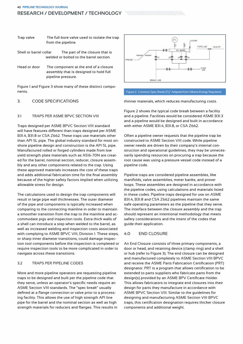
Trap valve The full-bore valve used to isolate the trap from the pipeline.
Shell or barrel collar The part of the closure that is welded or bolted to the barrel section.
Head or door The component at the end of a closure assembly that is designed to hold full pipeline pressure.
Figure 1 and Figure 3 show many of these distinct compo-nents.
3. CODE SPECIFICATIONS
3.1 TRAPS PER ASME BPVC SECTION VIII
Traps designed per ASME BPVC Section VIII standard will have features different than traps designed per ASME B31.4, B31.8 or CSA Z662. These traps use materials other than API 5L pipe. The global industry standard for most on-shore pipeline design and construction is the API 5L pipe. Manufactured rolled or forged cylinders made from low yield strength plate materials such as A516-70N are creat-ed for the barrel, nominal section, reducer, closure assem-bly and any other components related to the trap. Using these approved materials increases the cost of these traps and adds additional fabrication time for the final assembly because of the higher safety factors implied when utilizing allowable stress for design.
The calculations used to design the trap components will result in large pipe wall thicknesses. The outer diameter of the pipe and components is typically increased when comparing to the connecting mainline in order to maintain a smoother transition from the trap to the mainline and ac-commodate pigs and inspection tools. Extra thick walls of a shell can introduce a step when welded to the barrel, as well as increased welding and inspection costs associated with complying to ASME BPVC VIII, Division 1. These steps, or sharp inner diameter transitions, could damage inspec-tion tool components before the inspection is completed or require inspection tools to be more complicated in order to navigate across these transitions.
3.2 TRAPS PER PIPELINE CODES
More and more pipeline operators are requesting pipeline traps to be designed and built per the pipeline code that they serve, unless an operator’s specific needs require an ASME Section VIII standards. The “spec break” usually defined at a flange connection or valve prior to a process-ing facility. This allows the use of high strength API line pipe for the barrel and the nominal section as well as high strength materials for reducers and flanges. This results in
thinner materials, which reduces manufacturing costs.
Figure 2 shows the typical code break between a facility and a pipeline. Facilities would be considered ASME B31.3 and a pipeline would be designed and built in accordance with either ASME B31.4, B31.8, or CSA Z662.
Often a pipeline owner requests that the pipeline trap be constructed to ASME Section VIII code. While pipeline owner needs are driven by their company’s internal con-struction and operational guidelines, they may be unneces-sarily spending resources on procuring a trap because the root cause was using a pressure vessel code instead of a pipeline code.
Pipeline traps are considered pipeline assembles, like manifolds, valve assemblies, meter banks, and prover loops. These assembles are designed in accordance with the pipeline codes, using calculations and materials listed in these codes. Pipeline traps designed for use on ASME B31.4, B31.8 and CSA Z662 pipelines maintain the same safe operating parameters as the pipeline that they serve. The interface between the closure assembly and the trap should represent an intentional methodology that meets safety considerations and the intent of the codes that guide their application.
4.0 END CLOSURE
An End Closure consists of three primary components, a door or head, and retaining device (clamp ring) and a shell or hub (refer to Figure 3). The end closure can be designed and manufactured completely to ASME Section VIII BPVC and receive the ASME Parts Fabrication Certification (PRT) designator. PRT is a program that allows certification to be extended to parts suppliers who fabricate parts from the design(s) provided by an ASME BPV Certificate Holder. This allows fabricators to integrate end closures into their design for parts they manufacture in accordance with ASME BPVC Section VIII. Similar to the guidelines for designing and manufacturing ASME Section VIII BPVC traps, this certification designation requires thicker closure components and additional weight.
Figure 2: Common Spec Break [7] (* Adapted from Alberta Energy Regulator)
RESEARCH / DEVELOPMENT / TECHNOLOGY42 PIPELINE TECHNOLOGY JOURNAL

While complete design to ASME BPVC Section VIII is possible for the end closure, complete design is also not necessary nor recommended, considering that its function is not to provide access to the inside of a vessel, but to provide internal access to a pipeline system. Therefore, to maximize closure value and maintain industry safety standards, a recommended approach is to design the shell of the closure to pipeline codes and the head of the closure ASME Section VIII code. To further enhance safety and to comply with code, ASME BPVC Section VIII should be used
to incorporate a safety locking mechanism to prevent the ability to open the closure while it is under pressure. To visually explain the application of the codes and standards, Figure 4 shows the codes in effect near and across the launcher and receiver. The ASME Section VIII of the Boiler and Pressure Vessel Code is part of a robust industry resource for a variety of pressurized applications. Additional requirements towards an application will usually bring additional costs and additional effort. These addition-al efforts need be realized as a value-added benefit to the overall pipeline operation. In some instances, the addi-tional requirements can be a detriment when functionality is not fully integrated into the pipeline design. To use the trap valve as an equalization point, it makes safety, design, and operational sense to have balance on each side of the valve.
The pipeline codes determine how to safely design the trap and end closure shell / hub, and the Section VIII code determines how to safely design a flat plate for holding pressure. This approach leverages the design methodolo-gy and experience of the pipeline industry and the de-sign methodology and experience of the pressure vessel industry, allowing practical application of expertise for the best closure solution. It also allows for the shell design to utilize higher strength materials, allowing a smooth, low cost solution to mate with the trap’s major barrel. This is permitted with the pipeline codes
Figure 3: End Closure Components
Figure 4: Visual application of the ASME and API Codes
RESEARCH / DEVELOPMENT / TECHNOLOGYPIPELINE TECHNOLOGY JOURNAL 43

5. TRAP LENGTH
The design length of a trap is driven by the purpose, the available physical field site space, the use of the tools that are to be placed into the pipeline and the ability to man-age pipeline product during blowdown/drain. Traps that manage cleaning and batching scrapers can be shorter and take less time to blowdown/drain, and the distance to engage a scraper into the launcher can be shorter and easier to manage. Traps that will launch in-line inspection (ILI) tools need to be longer to accommodate the longer segmented tools. These longer traps increase the volume of pipeline product to expel prior to operating a closure.
This increased volume represents potential lost product and could require a flare or storage collection tank to be sized according to the trap length.
As an example, ILI tools vary in length depending on the tool technology and sensors type(s). As an example, 4 ILI tools are shown in Figure 5.
6. TRAP REDUCER
These pipeline components can be concentric — with both diameters sharing the same centre-line—or eccentric, with an inner surface remaining linear (Figure 6). Concentric
Figure 5: Type and Length of In-line Inspection Tools
Figure 6: Reducers
RESEARCH / DEVELOPMENT / TECHNOLOGY44 PIPELINE TECHNOLOGY JOURNAL

reducers add complexity to launching tools or scrapers due to the step up from the barrel to the nominal section. Eccentric reducers allow the scraper or tool to stay aligned with the pipeline’s centre-line during the launch process.
Eccentric reducers may cost extra initially, but their bene-fits to trap performance are realized for years. Of the two trap configurations, having an eccentric reducer at the launcher is the priority to minimize sensor damage during in-line inspection tool launch. Also, when longer ILI tools are used, it is sometimes necessary to pull them into the nominal and eccentric reducers aid in this process.
Two reasons to have an eccentric reducer on the receiver design are 1) stay consistent with the launcher design (trap standard) and 2) can launch scrapers or tools from the receiver in the future.
7. FLANGED OR WELDED TRAPS
Flanges at the trap/valve interface or the trap/closure interface provide flexibility to handling inspection tools and cleaning scrapers. Flanged traps can be configured to be short for the scraper usage and have bolted extensions for the times when the longer inspection tools are used. This flexibility optimizes the efficiency of the trap with minimal changeover. However, the flanged connections can be a source of leak path so managing this risk is usually an operator’s preference.
8. ADDITIONAL CONSIDERATIONS
Additional fabrication process monitoring that is desired to the trap design and manufacturing process, inspection and testing can be added to the requirement of the trap without requiring the full Section VIII designation. This way, the trap is completed with any added requirements the operator has determined to be necessary (a one-time experience) and the completed trap operates (a pipeline lifetime experience) in better harmony with the pipeline that it services.
9. CONCLUSION
When it comes to the design and operation of traps and receivers, knowing which specifications are being fol-lowed can influence decisions around what materials to use. These decisions impact both the timeline of a project and the budget. The guidelines and requirements of the pipeline operator may be more specific than the ASME, CSA and API codes and standards. It is recommended to understand the value of the traps that are specified and their purpose to the pipeline.
Be intentional with the scope of specifying a launcher or receiver for a pipeline. If a design requirement does
not provide a value to the pipeline and is not part of the operator’s written plan, unnecessary cost and delays can be experienced. As the guidelines and requirements of the pipeline operator are evaluated, match the needs of the pipeline operation with the equipment that is being purchased and placed into service.
10. ABBREVIATIONS/ ACRONYMS
API American Petroleum InstituteASME American Society of Mechanical EngineersBVPC Boiler and Pressure Vessel CodeCSA Canadian Standards AssociationPRT ASME Certification (Parts Fabrication)ILI In-line Inspection
11. ACKNOWLEDGEMENTS
The authors would like to acknowledge the support of T.D. Williamson and colleagues who helped in formulating the content of this paper.
References
1. Anon, “Transportation Systems for Liquid Hydrocarbons and Other Liquids”, American Society of Mechanical Engineers, ASME B31.4, 2012.
2. Anon, “Gas Transmission and Distribution Piping Systems”, American Society of Mechanical Engineers, ASME B31.8, 2018.
3. Anon, “Process Piping”, American Society of Mechanical Engineers, ASME B31.1, 2016.4. Anon “Pressure Vessels”, American Society of Mechanical Engineers, ASME BVPC Section
VIII, 2019.5. Anon “Specification for Linepipe”, American Petroleum Institute, API 5L, 2018.6. Anon, “Oil and Gas Pipeline Systems”, Canadian Standards Association, CSA Z662-19, 2019.7. Anon, “Pipelines – Requirements and Reference Tools”, Alberta Energy Regulator, March 20118. Morton, Kirkwood, “Specification Breaks for Launchers and Receivers”, 2019 PPIM-Middle East,
Muscat, Oman
Authors
Alan Morton
T.D.Williamson
Director, Product Development
Neil McKnight
T.D.Williamson
Business Development Manager
RESEARCH / DEVELOPMENT / TECHNOLOGYPIPELINE TECHNOLOGY JOURNAL 45

Prodromos Psarropoulos, Nikolaos Makrakis > National Technical University of Athens
Abstract
Depending on the local site conditions (i.e. bathymetry, geomorphology, geology), an offshore geohazard may have a detrimental impact on an offshore high-pressure gas pipeline during its lifetime. This fact is more pronounced in areas characterized by seismicity and the associated earthquake-related geohazards. Therefore, the design of an offshore pipeline should avoid any geohazardous area or alternatively should take into consideration the anticipated permanent ground displacements (PGDs) that may be developed on the seabed. The latter requires, apart from the quantitative assessment of the PGDs, a realistic assessment of the subsequent pipeline distress, in terms of com-pressive or tensile strains. The complete avoidance of a geohazardous area is a common design practise that may be performed either empirically/manually or utilizing a GIS-based software. Nevertheless, since the option of avoidance is not feasible in many real cases, crossing of a geohazardous area may be accepted, provided that the PGDs and the corresponding pipeline strains (that are quantitatively assessed, usually via finite-element simulations) are below the allowable levels. Since the numerical simulations on a case-by-case basis are demanding and time-consuming pro-cedures, modern tools based on Artificial Intelligence (AI) may be utilized to substantially reduce the computational cost. Based on the aforementioned, scope of the current study is the application of AI, and more specifically Artificial Neural Networks (ANNs), in the design of offshore pipelines against geohazards. In particular, the prediction of the response of offshore pipelines that cross active seismic faults has been studied in order to develop a smart GIS-based tool capable to indicate the optimal pipeline routing(s). Through a realistic case study in the Mediterranean Sea, it was shown that ANNs can reliably predict the distress of offshore pipelines subjected to PGDs due to active seismic faults, provided that they are based on datasets that are extracted from accurate finite-element simulations.
Artificial Intelligence in the Design of Offshore Pipelines against Geohazards

1. INTRODUCTION
During the last decades many offshore gas pipelines have been constructed worldwide, while many more are expect-ed to be installed in the near future. Furthermore, intense seismicity in several areas and improved environmental standards are directly related to the safety requirements in construction and maintenance of offshore gas pipelines. Hence, an optimal pipeline route selection could undeni-ably minimize the probability of failure of such infrastruc-tures and prevent devastating economic, environmental and social consequences. One of the most critical factors which affect the procedure of offshore pipeline optimal route selection is related to the offshore geohazards. The latter consist geological and hydro-geological processes which can lead to deformations of the seabed of all ocean-ic environments that are potential threats to any offshore structure (Randolph and Gourvenec, 2017). The main off-shore geohazards, which are capable of causing failure of an offshore gas pipeline, are submarine slides, shallow gas and dissociation of gas hydrates, shallow water flow, mud volcanism, and seismicity.
Nevertheless, in regions characterized by seismicity, the geomorphology of the seabed (e.g., either steep submarine slopes vulnerable to offshore landslides or valleys with soft sediments), the geological and tectonic conditions may lead to offshore earthquake-related geohazards, which can be categorized as dynamic and quasi-static, such as:
a. strong ground motion (i.e., vibrations of the seafloor), b. tectonic movements and seismic fault ruptures, c. slope instabilities (i.e., submarine landslides), d. soil-liquefaction phenomena.
During an earthquake, an offshore gas pipeline (charac-terized by limited mass) may be slightly distressed by the inertial forces developed due to the strong ground motion. On the contrary, an offshore pipeline may fail due to the potential PGDs on the seafloor as a result of an offshore earthquake-related geohazard. PGDs are considered as the most severe type of loading, since the induced strains may become fairly large.
Recently, the authors of the current paper and their colleagues developed a smart decision-support tool to optimize the route of an onshore and/or offshore pipeline taking into account the potential geohazards under static and seismic conditions (Psarropoulos et al., 2019; Makrakis et al., 2020). The tool can support engineers in making a decision regarding optimal route selection of a pipeline through: (a) the qualitative and quantitative assessment of the major geohazards along a possible pipeline routing, (b) the quantitative assessment of their potential impact on the pipeline, and (c) the selection of the optimum pipeline route. The tool combines:
a. a Geographic Information System (GIS) provided by ESRI (ArcGIS) (ESRI, 2016) that • manipulates all the available spatiotemporal geo-data, and• performs the final route optimization
b. the Finite Element software ABAQUS (Simulia, 2014) which is capable of performing • realistic geotechnical analyses and reliable as-sessments of the examined geohazards, and • soil-pipe interaction simulations for the evaluation of the pipeline distress.
Additionally, the tool is based on a multi-criteria process hence it is also capable of selecting the optimum routing taking also into consideration many other criteria apart from the geohazards, such as distance minimization or avoidance of “no-go” areas.
Scope of the present study is to demonstrate an improved version of the aforementioned smart tool, which includes ANNs that have been trained through the MATLAB com-putational platform (MATLAB, 2015). The efficiency of the improved tool has been verified through a case study in the Mediterranean Sea.
2. SIMULATION OF FAULT-RUPTURE PROPAGATION & SOIL-PIPE INTERACTION
As it was mentioned, the current study focuses on the geo-hazard of active seismic faults and their potential impact on pipelines, taking also into account the soft sediments that usually exist at the seafloor. The seismic faults may be categorized depending on their location and the geological conditions as “outcropped” or “covered” (i.e., blind). The rupture of an outcropped fault is a direct threat to a cross-ing pipeline, while in the case of a covered fault the local seabed conditions may alter the fault rupture propagation and the PGD pattern at the seafloor. This alteration inevita-bly would cause straining to the pipeline, which should be designed to sustain this fault-induced strains. Unfortunate-ly, the assessment of the faulting hazard (dislocation and angle of emergence) is possible only within rock forma-tions. Whereas the fault rupture at the bedrock is unambig-uously defined by the dip angle and the magnitude of the expected dislocation (i.e., offset), as the rupture propagates through the softer soil layers, it usually deviates, bends and causes a rather smooth deformation of the surface, at least when compared with the abrupt dislocation at the rock (Figure 1).
PGD is a function of the fault displacement and angle, and the mechanical and geometrical properties of the sediments. To predict the deformation of the soil surface induced by the rupture propagation, a special analysis is
RESEARCH / DEVELOPMENT / TECHNOLOGYPIPELINE TECHNOLOGY JOURNAL 47

required. The fault rupture propagation analysis can be performed with a finite-element software. Such numerical results demonstrate that the existence of sediments cover-ing the hard bedrock leads to the following phenomenon: the applied fault offset within a very narrow zone at the bedrock is transformed to a PGD which is extended along a certain zone at the seafloor. This phenomenon will certain-ly lead to lower tensile strain levels at any pipeline lying on the seafloor (compared to the case of a pipeline lying on a rocky formation).
The impact of the sediments to the PGDs at the surface has been investigated in many studies of the literature, and a general conclusion was the fact that may be very crucial for the design. Therefore, further research is needed in cas-es where the optimal route of offshore pipelines crosses blind faults with soft sediments. The latter can be per-formed by estimating and assessing the geometrical and mechanical properties of the sediments and the fault type, as well as the process of the induced offset at the bedrock. Subsequently, the assessed PGDs can be imposed on the pipeline as a quasi-static loading and the pipeline distress can be calculated (Trimintziou et al., 2015).
In the case of an offshore pipeline crossing an active seismic fault, the pipeline behaviour could be analyzed as a typical soil-structure interaction (SSI) problem. The term “structure” is used to describe the pipeline itself, while “soil” represents the sediments of the seafloor. In the case that sediments do not exist (e.g. at the landfall areas), “soil” represents the rocky formations. The verification of the pipeline against fault rupture should be performed utilizing a finite-element tool, while the compliance of the sediments around the pipeline is usually represented by soil springs at various directions, depending on the cir-cumstances. The properties of the soil springs are directly
related to the mechanical properties of the sediments, while the finite-element analyses should account for non-linear soil and pipeline behaviour. The analysis of the pipeline could be performed with three-dimensional (3-D) numerical models in which the pipeline is simulated with pipe finite elements or shell finite elements. More details on the finite-element modelling of pipelines can be found in Psarropoulos et al., 2021.
3. ARTIFICIAL INTELLIGENCE & AR-TIFICIAL NEURAL NETWORKS
In general, AI methods are used either to reduce the computational cost, or when the complexity and/or the size of the problem prohibit the use of conventional tech-niques (Lagaros et al., 2006). Especially, ANNs have been widely-used in many fields of science and technology, as well as into an increasing number of various engineering applications (Tsompanakis et al., 2008). Simulation, in-verse simulation and identification problems are the most popular paradigms among general engineering problems that can be analyzed by means of SC techniques. Simula-tion is linked with direct methods of numerical analysis, i.e. for known inputs and characteristics of the system under investigation the unknown outputs (responses of the system) are searched. In contrast, inverse simulation (for example the identification of an unknown load of a given structural response) takes place if inputs represent known responses of the system and the “excitations” that caused this behaviour of the certain system are searched as outputs. Identification is also associated with the inverse analysis of systems, including structures and materials. In this case excitations and responses are known and characteristics of the system are searched. Apart from the aforementioned ANN-based applications in various engi-neering problems, an increasing number of articles have been published over the last decades where the efficient implementation of ANNs in geotechnical earthquake engi-neering is presented.
4. SMART DECISION-SUPPORT TOOL FOR ROUTE OPTIMIZATION
As aforementioned, the authors and their colleagues, uti-lizing the environment of GIS, had developed a smart-deci-sion support tool which was capable to optimize the route of offshore pipelines. It is noted that the tool can be used for the route optimization of onshore pipelines as well. The optimization of offshore pipelines is performed via a multi-criteria analysis, taking also into account the offshore geohazards (i.e., the problematic areas and the potentially problematic areas). In the initial version of the tool, the main criteria were (a) the pipeline length minimization (b) the avoidance of “no-go” areas (e.g., shipwrecks or bombs), and (c) avoidance of the (potentially) problematic areas or minimization of pipeline length at the crossings with
Figure 1: Schematic of the fault rupture propagation through sediments
RESEARCH / DEVELOPMENT / TECHNOLOGY48 PIPELINE TECHNOLOGY JOURNAL

these areas. It is noted that each criterion can be weighted, depending on the circumstances and the requirements of the user.
In its standard version, the tool has been combined with the FE software ABAQUS, which is capable of performing two decoupled types of analyses / simulations:
a) Geotechnical analyses / simulationsThese analyses are performed to simulate the geohazard-ous areas along the offshore pipeline and to realistically quantify the geohazard (usually in terms of PDGs). They are performed in two (or even three) dimensions, and they are based on the available geodata that have initially been in-corporated in the GIS system (i.e., bathymetrical, geological, geotechnical, seismotectonical and seismological data). The analyses may quantify the main earthquake-related geohazards.
b) Soil-structure interaction (SSI) analyses The SSI analyses are performed in order to assess the distress of the pipeline (i.e., stresses and strains) when the pipeline is subjected to the aforementioned PGDs. Then, the numerical results of the SSI analyses, along with the allowable levels of distress are taken into consideration by the GIS tool to find the optimum routing.
Initially, two-dimensional finite element (FE) models are created in ABAQUS. In the first model the active fault rupture is simulated, while in the second model the impact of the imposed displacements are investigated. Numer-ous parametric analyses are performed, that are emerged through the alteration of the seabed sediment thickness (H), the angle of the internal friction (φ) and the cohesion (c) of the soil. For each and every one of the models several
analyses take place and results are yielded regarding the displacements of the seabed (U1, U2) and the pipe’s strain.
As shown in Figure 2, the whole procedure combines GIS and FE analyses and includes four steps. The prediction of the response of offshore pipelines that cross active seismic faults has been studied to improve the smart tool described in the previous section.
As shown in Figure 3, the whole procedure combines GIS and ANNs (that have been trained by the results of pre-per-formed FE analyses) and includes four main steps. It is not-ed that in both versions the comparison of pipeline strains with the allowable levels (in Step 3) will actually lead to the distinction between (potentially) problematic areas and critical areas, while Step 4 should take into account all the criteria (i.e., pipeline length minimization, avoidance of “no-go” areas, and avoidance of all critical areas which cannot be crossed).
5. CASE STUDY: AN OFFSHORE GAS PIPELINE IN THE MEDITERRANEAN SEA
5.1 APPLICATION OF THE STAN-DARD VERSION OF THE SMART TOOL
The standard version of the tool had been applied to a case study referring to a gas pipeline that will be possibly constructed in the Eastern-Mediterranean Sea, between Cyprus and Crete, as shown in Figure 4. As the pipeline approaches Crete, it is expected to cross three seismic fault zones, and in particular: (i) the East-Mediterranean Ridge, (ii) the Hellenic Trench, and (iii) the Cretan-Rhodes Ridge, as represented in Figure 5. The examined area is
Figure 2: The four main steps of the standard version of the smart tool. Figure 3: The four main steps of the improved version of the smart tool.
RESEARCH / DEVELOPMENT / TECHNOLOGYPIPELINE TECHNOLOGY JOURNAL 49

very active tectonically, characterized by displacements at the bedrock of the order of 2m during the 50-year lifetime period of the pipeline (Apel et al., 2007).
Undoubtedly, the role of sediments covering an active seismic fault is expected to be beneficial for the pipeline design. In the area of South-Eastern Mediterranean Sea sediment thickness varies from 0 to 800m (Gennesseaux and Winnock, 1993). The maximum depth where the pipe-line will be placed in this area is approximately 2,5km. The high-pressure offshore gas pipeline is assumed to have an outer diameter of D = 0.66m, and wall thickness t = 27mm.Despite the fact that the thickness of the sediments, H, may be of the order of 800m in this region, in the present case study three rather conservative scenarios with respect to the thickness of the sedimentary layers were examined: 50 m, 100 m, and 150 m. Indicative results for the case of H = 100 m are depicted in Figure 6a. It is obvious that at the surface of the seabed the PGDs are smoother than the PGDs at the bedrock. Additionally, Figure 6 presents the results of the numerical simulations of the soil-structure interaction in terms of axial deformation of the pipeline crossing the seismic fault. It is apparent that when the pipeline crosses an active seismic fault zone with sedi-ments of zero or small thickness, then it will be exposed to greater distress.
Finally, Figure 7 shows the final pipeline route that has been proposed by the smart decision-support tool. After the assessment of the quantitative geohazard and of the subsequent pipeline distress, the (potentially) problematic area at the East Mediterranean Ridge may be crossed with safety. The Hellenic Trench can be avoided, despite the fact that its limits are not so well defined. Nevertheless, it is has to be emphasized that crossing of the Cretan-Rhodes Ridge may be extremely risky since the sediments in this area are rather limited, apart from the extra geohazard of slope instability that has not been examined in the current study.
5.2 APPLICATION OF THE IMPROVED VERSION OF THE SMART TOOL
As it was mentioned in Section 4, in order to train the ANNs, the performance of geotechnical and structural FE analyses is required in advance. Therefore, a parametric study has been pre-performed utilizing software ABAQUS, where the main parameters are the geometrical and me-chanical properties of the sediments (i.e. thickness H, inter-nal angle of friction, φ, and cohesion, c, while the PGDs in x and y direction (i.e. U1, U2), as well as the pipe axial strain ε, are the final numerical results. Regarding the parameters of the pre-performed FE analyses, H ranges between 45m and 100m, φ ranges between 16o and 30o, and c varies from 20kPa to 40kPa. Note that parameters H, φ, and c are the input variables for the training procedure of ANNs, while U1, U2 and ε are the
output variables. After their training through the MATLAB computational platform, ANNs are applied in order to rap-idly predict PGDs (i.e., U1 and U2) and the pipeline distress (i.e., ε) for any combination of input values.
Therefore, trained ANNs were initially configured, utilizing the suggested values of the software for the neural net-work architecture corresponding to 10 hidden levels as well as for the training samples which amount to 70%, valida-tion samples 15% and 15% control samples. Then, the ability
Figure 4: The area of interest between Cyprus and the island of Crete, Greece. The yellow points show the starting point in Cyprus and the end point in Crete.(source: Google Earth)
Figure 5: Bathymetry of the East Mediterranean Sea and main active fault zones: (i) East Mediterranean Ridge, (ii) Hellenic Trench, and (iii) Cretan-Rhodes Ridge.
Figure 6: Numerical results: (a) the differential settlement of the sedimentary layer due to fault rupture, and (b) the axial pipeline deformations.
RESEARCH / DEVELOPMENT / TECHNOLOGY50 PIPELINE TECHNOLOGY JOURNAL

of these neural networks to predict random data belonging to the range of the preliminary FE analyses was tested. Ta-ble 1 shows the errors in the prediction of U1 and ε, where it becomes evident that ANNs can predict U1 very efficiently, with maximum errors less than 1%, while the prediction of ε has a less reliable performance.
The results were compared with the corresponding data of the neural network for method testing. The prediction error for the axial strain of the pipe was smaller than 0.5%. In conclusion, the objectives were met in a sufficient degree. It was proved that ANNs can predict the behaviour of sub-sea pipelines, which are subjected to the displacements of active faults’ rapture, provided that they are based on datasets that are extracted from accurate FE simulations.
6. CONCLUSIONS
The current study focuses on route optimization of offshore pipelines taking into consideration the poten-tial crossing of extensive submarine areas, facing the geohazard of active fault rupture. Combining the capabil-ities of ArcGIS platform with the FE software ABAQUS, a smart decision-support tool had been developed in the past by the authors and their colleagues to facilitate: (a) the qualitative and quantitative assessment of the major earthquake-related geohazards along a possible lifeline routing, (b) the quantitative assessment of their potential impact on the lifeline, and (c) the selection of the optimum pipeline route. In the current study the standard version of the smart tool has been improved with the application of AI. The tool has been applied in a characteristic case study
in a region characterized by: (a) great potential for offshore development in the near future, and (b) high seismicity and consequent earthquake-related geohazards. Although the new tool requires further improvement, the preliminary results demonstrate its capability to handle, analyze and manage all the available spatial data that are directly or indirectly linked with the earthquake-related geohazards and to support the geoscientists and engineers to quan-tify the geohazards and the relevant risks, and to make a prompt and clear distinction between the actual critical ar-eas that a pipeline cannot cross and the non-critical areas that a pipeline can safely cross.
Figure 7: The final pipeline route that has been proposed by the decision-sup-port tool.
References
1. Apel, E., Bürgmann, R., Serpelloni, E., 2007. Rigid Block Motion, Interseismic Strain, and Backarc Deformation in the Aegean, in: AGU Fall Meeting Abstracts.
2. ESRI (Environmental Systems Resource Institute), 2016. ArcGIS Desktop: Release 10.4. Redlands CA.
3. Gennesseaux, M., Winnock, E., 1993. Thickness of Mediterranean plio-quaternary sediment [WWW Document]. Charts Div. Head Dep. Navig. Oceanogr. Russ. under Auth. Intergov. Oce-anogr. Comm. UNESCO. URL https://www.ngdc.noaa.gov/mgg/ibcm/ibcmsedt.html.
4. Lagaros, N.D., Tsompanakis, Y., 2006. Intelligent computational paradigms in earthquake engineering, Idea Publi. ed.
5. Makrakis, N., Psarropoulos, P., Chatzidakis, D., Tsompanakis, Y., 2020. Route Optimization of Offshore Lifelines Taking Into Account Potential Earthquake-Related Geohazards. Front. Built Environ. 6, 1–16. https://doi.org/10.3389/fbuil.2020.00112
6. Psarropoulos, P.N., Antoniou, A.A., Tsompanakis, Y., 2019. Offshore earthquake-related geoha-zards and route optimization of offshore pipelines, risers, and cables, in: Pipeline Technology Conference, Berlin.
7. Psarropoulos, P.N., Makrakis, N., Boutikas, K., Papathoma, M., 2021. Artificial Neural Networks in the Design of Offshore Pipelines against Geohazards: Pipeline Technology Conference, Berlin.
8. Randolph, M., Gourvenec, S., 2017. Offshore geotechnical engineering, Offshore Geotechnical Engineering. https://doi.org/10.1201/9781315272474
9. Simulia, 2014. Abaqus 6.14 analysis user’s manual.10. The MathWorks Inc., 2015. Matlab Release 2015a [WWW Document]. Massachusetts, United
States.11. Trimintziou, M.S., Sakellariou, M.G., Psarropoulos, P.N., 2015. Designing Offshore Pipelines
Facing the Geohazard of Active Seismic Faults Designing Offshore Pipelines Facing the Geoha-zard of Active Seismic Faults. Int. J. Civil, Environ. Struct. Constr. Archit. Eng.
12. Tsompanakis, Y., Lagaros, N.D., Stavroulakis, G.E., 2008. Soft computing techniques in parame-ter identification and probabilistic seismic analysis of structures. Adv. Eng. Softw. https://doi.org/10.1016/j.advengsoft.2007.06.004
Table 1: Errors of the ANNs for U1 and ε.
Authors
Prodromos Psarropoulos
National Technical University of
Athens
Structural & Geotechnical
Engineer
Nikolaos Makrakis
Independent Consultant
Surveying & Earthquake Engineer
RESEARCH / DEVELOPMENT / TECHNOLOGYPIPELINE TECHNOLOGY JOURNAL 51

.
Association
IAOT - International Association of Oil Transporters
Czech Republicwww.iaot.eu/
DVGW - German Technical and Scientific Association for Gas and Water
Germanywww.dvgw.de
Automation
Siemens EnergyGermanywww.siemens.com
Certification
Bureau VeritasGermanywww.bureauveritas.de
DNVNorwaywww.dnvgl.com
TÜV SÜD Indutrie ServiceGermanywww.tuev-sued.de/is
Cleaning
Reinhart HydrocleaningSwitzerlandwww.rhc-sa.ch/rhc/
Coating
DensoGermanywww.denso.de
Kebulin-gesellschaft KettlerGermanywww.kebu.de
POLINOM Russiawww.rikol.ru
Polyguard Products United Stateswww.polyguard.com
Premier CoatingsUnited Kingdomwww.premiercoatings.com/
RPR TechnologiesNorwaywww.rprtech.com/
ShawcorUnited Stateswww.shawcor.com
Sulzer Mixpac Switzerlandwww.sulzer.com
TDC InternationalSwitzerlandwww.tdc-int.com
TIAL Russiawww.tial.ru
TIB ChemicalsGermanywww.tib-chemicals.com
Construction
BIL - Federal German Construction Enquiry
Portal
Germanywww.bil-leitungsauskunft.de
Herrenknecht Germanywww.herrenknecht.com
IPLOCA - International Pipe Line & Offshore Contractors Association
Switzerlandwww.iploca.com
LiderrollBrasilwww.liderroll.com.br
LogICFrancewww.logic-sas.com
COMPANY DIRECTORY52 PIPELINE TECHNOLOGY JOURNAL

MAX STREICHERGermanywww.streicher.de/en
Petro IT Irelandwww.petroit.com
VACUWORXNetherlandswww.vacuworx.com
Vintri Technologies Canadawww.vintritech.com
VlentecNetherlandswww.vlentec.com
Construction Machinery
MaatsNetherlandswww.maats.com
Worldwide GroupGermanywww.worldwidemachinery.com
VIETZGermanywww.vietz.de
Engineering
ILF Consulting Engineers Germanywww.ilf.com
KÖTTER Consulting EngineersGermanywww.koetter-consulting.com
Inline Inspection
3P ServicesGermanywww.3p-services.com
A.Hak Industrial ServicesNetherlandswww.a-hak-is.com
Baker HughesUnited Stateswww.bakerhughes.com
Intero Integrity ServicesNetherlandswww.intero-integrity.com/
Kontrolltechnik Germanywww.kontrolltechnik.com
KTN AS Norwaywww.ktn.no
LIN SCAN United Arab Emirateswww.linscaninspection.com
NDT Global Germany www.ndt-global.com
Pipesurvey InternationalNetherlandswww.pipesurveyinternational.com
PPSA - Pigging Products and Services AssociationUnited Kingdomwww.ppsa-online.com
RomstarMalaysia www.romstargroup.com
RosenSwitzerlandwww.rosen-group.com
Ametek – Division Creaform Germany
www.creaform3d.com
Applus RTD Germanywww.applusrtd.com
EMPITGermanywww.empit.com
INGUCanadawww.inguc.com
COMPANY DIRECTORYPIPELINE TECHNOLOGY JOURNAL 53

Integrity Management
Metegrity Canadawww.metegrity.com
Pipeline Innovations United Kingdomwww.pipeline-innovations.com
Leak Detection
Asel-TechBrazilwww.asel-tech.com
Atmos InternationalUnited Kingdomwww.atmosi.com
EntegraUnited Stateswww.entegrasolutions.com
Fotech Solutions United Kingdomwww.fotech.com
GOTTSBERG Leak DetectionGermanywww.leak-detection.de
MSA Germanywww.MSAsafety.com/detection
OptaSenseUnited Kingdomwww.optasense.com
Monitoring
Airborne Technologies Austriawww.airbornetechnologies.at
Krohne Messtechnik Germanywww.krohne.com
PHOENIX CONTACT Germanywww.phoenixcontact.de/prozess
SolSpec United Stateswww.solspec.solutions
Hifi Engineering Canadawww.hifieng.com
PSI SoftwareGermanywww.psioilandgas.com
VallourecFrancewww.vallourec.com
Materials
Prisma PhotonicsIsraelwww.prismaphotonics.com
Associated Technology Pipeline LtdUnited Kingdomwww.atpuk.co.uk
PermAlertUnited Stateswww.permalert.com
Pergam Suisse Switzerlandwww.pergam-suisse.ch
Fibersonics United Stateswww.fibersonics.com
SolAres (Solgeo / Aresys) Italywww.solaresweb.com
OGE (Open Grid Europe) Germanywww.oge.net
Operators
AP Sensing Germanywww.apsensing.com
sebaKMT Germanywww.sebakmt.com
COMPANY DIRECTORY54 PIPELINE TECHNOLOGY JOURNAL

TransneftRussiawww.en.transneft.ru/
Qualification & Recruitment
YPPE - Young Pipeline Professionals Europe International
www.yppeurope.org
Pump and Compressor Stations
TNO The Netherlandswww.pulsim.tno.nl
Repair
CITADEL TECHNOLOGIESUnited Stateswww.cittech.com
Clock Spring NRIUnited Stateswww.clockspring.com
T.D. WilliamsonUnited Stateswww.tdwilliamson.com
Research & Development
Pipeline Transport Institute (PTI LLC)Russiawww.en.niitn.transneft.ru
Safety
DEHN & SÖHNEGermanywww.dehn-international.com/en
HIMAGermanywww.hima.de
Signage
Franken PlastikGermanywww.frankenplastik.de/en
Surface Preparation
MONTI - Werkzeuge GmbH Germanywww.monti.de
Trenchless Technologies
BohrtecGermanywww.bohrtec.com
GSTT - German Society for Trenchless Technology
Germanywww.gstt.de
Rädlinger Primus Line Germanywww.primusline.com
Valves & Fittings
AUMAGermanywww.auma.com
Zwick ArmaturenGermanywww.zwick-armaturen.de
Pipeline Technology Journal
Further boost your brand awareness and list your company within the ptj - Company Directory
www.pipeline-journal.net/advertise
TRAPILFrancewww.trapil.com/en/
COMPANY DIRECTORYPIPELINE TECHNOLOGY JOURNAL 55

Find Us! Young Pipeline
Professionals Europe
yppeurope.org
Host a webinar / site visit Promote membership Provide support / mentoring Sponsor a YPPE event Don’t just be in
the industry, be a part of it
IF YOU ARE READING THIS WE NEED YOU
Event Calendar
Infrastructure Development Africa 15 November 2021 Online
gat | wat 202124 - 25 November 2021
Cologne & Online
17th Pipeline Technology Conference 7 - 10 March 2022 Berlin, Germany & Online
5th Trenchless Romania - Conference & Exhibition 19 October 2021 Bucharest, Romania
6th Virtual Pipeline Summit „Offshore Pipeline Tech-nologies“
15 December 2021 Online

Pipeline Technology Journal
PTJ ADVERTISING & MARKETING SERVICES SUPPORTING
YOUR CORPORATE COMMUNICATION
www.pipeline-journal.net/advertise

We are taking energy forward–making your pipeline assets safer, cleaner, and more efficient
We’re helping operators manage their assets and prepare for their energy future, partnering to deliver data, technology, solutions, and expertise.
Our unique portfolio includes:
• Advanced pipeline inspection technologies and integrity engineering expertise to drive enhanced pipeline safety
• Extensive pre-commissioning and maintenance services help enable event free start-up, improve efficiency, and maximize throughput
• World-class rotating equipment, including the NovaLT™ hydrogen blend turbine for gas and zero-emission compression solutions —providing optimal performance while reducing carbon footprint
bakerhughes.com
BakerHughes_PTC_Ad-022521.indd 1BakerHughes_PTC_Ad-022521.indd 1 2021-02-25 10:40 AM2021-02-25 10:40 AM