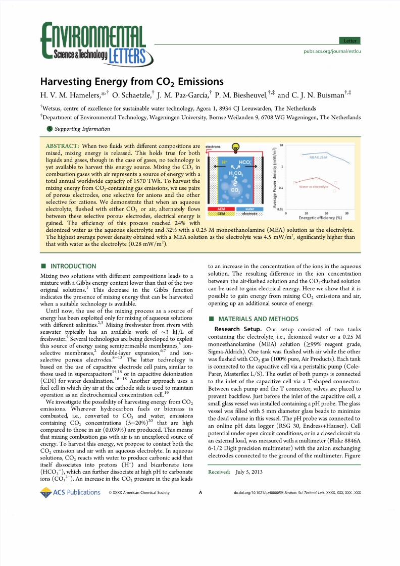
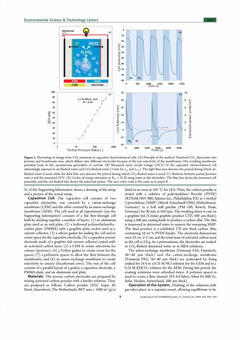
Harvesting Energy from CO 2 Emissions H. V. M. Hamelers,* ,† O. Schaetzle, † J. M. Paz-García, † P. M. Biesheuvel, † ,‡ and C. J. N. Buisman † ,‡ † Wetsus, centre of excellence for sustainable water technology, Agora 1, 8934 CJ Leeuwarden, The Netherlands ‡ Department of Environmental Technology, Wageningen University, Bornse Weilanden 9, 6708 WG Wageningen, The Netherlands * S Supporting Information ABSTRACT: When two fluids with diff erent compositions are mix ed, mi xin g ene rgy is rel eased. This hol ds tru e for both liquids and gases, though in the case of gases, no technology is yet available to harvest this energy source. Mixing the CO 2 in combustion gases with air represents a source of energy with a total annual worldwide capacity of 1570 TWh. To harvest the mixing energy from CO 2 -containing gas emissions, we use pairs of porous electrodes, one selective for anions and the other selective for cations. We demonstrate that when an aqueous electrolyte, flushed with either CO 2 or air, alternatel y flows between these selective porous electrodes, electrical energy is ga ined. The efficienc y of th is pr ocess reac hed 24% wi th deionized water as the aqueous electrolyte and 32% with a 0.25 M monoethanolamine (MEA) solution as the electrolyte. The highest average power density obtain ed with a MEA soluti on as the elect rolyt e was 4.5 mW/ m 2 , significantly higher than that with water as the electrolyte (0.28 mW/m 2 ). ■ INTRODUCTION Mixing two solutions with di ff erent compositions leads to a mixture with a Gib bs energy content lower than that of the two origin al solutions. 1 Th is dec rease in the Gi bbs funct io n indicates the presence of mixing energy that can be harvested when a suitable technology is available. Until now, the use of the mixing process as a source of energy has been exploited only for mixing of aqueous solutions with diff erent salinities. 2,3 Mixing freshwater from rivers with sea wat er t y pi ca ll y ha s an avai la bl e wo rk of ∼3 kJ/L of freshwater. 4 Several technologies are being developed to ex ploit this source of energy using semipermeable membranes, 5 ion- selective membra nes, 2 double-la yer expansion, 6 ,7 and io n- sel ecti ve poro us elec trod es. 8−13 The la tte r tec hnolo gy is based on the use of capaciti ve electrode cell pairs, similar to those used in supercapacitors 14,15 or in capacitive deionization (CDI) for water desalination. 16−18 Another approach uses a fuel cell in which dry air at the cathode side is used to maintain operation as an electrochemical concentration cell. 19 We investigate the possibility of harvesting energy from CO 2 emissions. Wherever hydrocarbon fuels or biomass is combus ted , i. e., converte d to CO 2 and w ater, emiss ions contai ning CO 2 concentrations (5−20%) 20 that are hi gh compared to those in air (0.039%) are produced. This means that mixing combustion gas with air is an unexplored source of energy. To harvest this energy, we propose to contact both the CO 2 emission and air with an aqueous electrolyte. In aqueous solutions, CO 2 reacts with water to produce carbonic acid that itself di sso cia tes int o pro ton s (H + ) and bicarbonate ions (HCO 3 − ), which can further dissociate at high pH to carbonate ions (CO 3 2− ). An incre ase in the CO 2 pressure in the gas leads to an increase in the concentration of the ions in the aqueous solution. The resul ting di ff ere nce in the ion co nce ntr ati on between the air- flushed solution and the CO 2 -flushed solution can be used to gain electrical energy. Here we show that it is possible to gain energy from mixing CO 2 emissions and air, opening up an additional source of energy. ■ MATERIALS AND METHODS Research Setup. Our setup consisted of two ta nks containing the electrolyte, i.e., deionized water or a 0.25 M mono ethanolamine (MEA) solu tion (≥99% rea gen t grade, Sigma-Aldrich). One tank was flushed with air while the other was flushed with CO 2 gas (100% pure, Air Products). Each tank is connected to the capacitive cell via a peristaltic pump (Cole- Parer, Masterflex L/S). The outlet of both pumps is connected to the inlet of the capacitive cell via a T-shaped connector. Between each pump and the T connector, valves are placed to prevent back flow. Just before the inlet of the capacitive cell, a small glass vessel was installed containing a pH probe. The glass vessel was filled with 5 mm diameter glass beads to minimize the dead volume in this vessel. The pH probe was connected to an online pH data logger (RSG 30, Endress+Hauser). Cell potential under open circuit conditions, or in a closed circuit via an external load, was measured with a multimeter (Fluke 8846A 6-1/2 Digit precision multimeter) with the anion exchanging electrodes connected to the ground of the multimeter. Figure Received: July 5, 2013 Letter pubs.acs.org/journal/estlcu © XXXX American Chemical Society A dx.doi.org/10.1021/ez4000059| Environ. Sci. Technol. Lett. XXXX, XXX, XXX−XXX