public input no. 3-nfpa 24-2015 [ new section after … · awwa c206, field welding of steel water...
TRANSCRIPT

Public Input No. 3-NFPA 24-2015 [ New Section after 1.4 ]
A.1.4
It is the intent of the committee to recognize that future editions of this standard are a further refinement ofthis edition and earlier editions. The changes in future editions will reflect the continuing input of the fireprotection community in its attempt to meet the purpose stated in this standard. Compliance with allrequirements of a future edition could be considered as providing an equivalent level of system integrity andperformance of the system.
Statement of Problem and Substantiation for Public Input
Many AHJ's will not recognize future editions. This annex note is intended to give guidance that use of an entire future edition of the standard could be considered an equivalency as allowed in 1.4. This language will be proposed to other sprinkler standards and has been accepted by NFPA 14 & NFPA 25.
Submitter Information Verification
Submitter Full Name: Peter Schwab
Organization: Wayne Automatic Fire Sprinkler
Street Address:
City:
State:
Zip:
Submittal Date: Tue Dec 22 10:32:25 EST 2015
Committee Statement
Resolution: FR-21-NFPA 24-2016
Statement: Many AHJ's will not recognize future editions. This annex note is intended to give guidance that useof an entire future edition of the standard could be considered an equivalency as allowed in 1.4. Thislanguage will be proposed to other sprinkler standards and has been accepted by NFPA 14 & NFPA25.
See attached document for new language in A.1.4.
National Fire Protection Association Report http://submittals.nfpa.org/TerraViewWeb/ContentFetcher?commentPara...
1 of 51 11/4/2016 7:43 AM

Public Input No. 1-NFPA 24-2015 [ Chapter 2 ]
Chapter 2 Referenced Publications
2.1 General.
The documents or portions thereof listed in this chapter are referenced within this standard and shall beconsidered part of the requirements of this document.
2.2 NFPA Publications.
National Fire Protection Association, 1 Batterymarch Park, Quincy, MA 02169-7471.
NFPA 13, Standard for the Installation of Sprinkler Systems, 2016 edition.
NFPA 13D, Standard for the Installation of Sprinkler Systems in One- and Two-Family Dwellings andManufactured Homes, 2016 edition.
NFPA 13R, Standard for the Installation of Sprinkler Systems in Low-Rise Residential Occupancies, 2016edition.
NFPA 20, Standard for the Installation of Stationary Pumps for Fire Protection, 2016 edition.
NFPA 22, Standard for Water Tanks for Private Fire Protection, 2013 edition.
NFPA 25, Standard for the Inspection, Testing, and Maintenance of Water-Based Fire Protection Systems,2014 edition.
NFPA 780, Standard for the Installation of Lightning Protection Systems, 2014 edition.
NFPA 1961, Standard on Fire Hose, 2013 edition.
NFPA 1963, Standard for Fire Hose Connections, 2014 edition.
2.3 Other Publications.
2.3.1 ASME Publications.
American Society of Mechanical Engineers ASME International , Two Park Avenue, New York, NY10016-5990.
ASME B1.20.1, Pipe Threads, General Purpose (Inch), 2001 2013 .
ASME B16.1, Gray Iron Pipe Flanges and Flanged Fittings, Classes 12, 125, and 250, 2010 2015 .
ASME B16.3, Malleable Iron Threaded Fittings, Classes 150 and 300, 2006 2011 .
ASME B16.4, Gray Iron Threaded Fittings, Classes 125 and 250, 2006 2011 .
ASME B16.5, Pipe Flanges and Flanged Fittings NPS 1⁄2 through 24, 2013.
ASME B16.9, Factory-Made Wrought Steel Buttweld Fittings, 2007 2012 .
ASME B16.11, Forged Steel Fittings, Socket- Welded and Threaded, 2005 2011 .
ASME B16.18, Cast Bronze Solder Cast Copper Alloy Solder Joint Pressure Fittings, 2001 2012 .
ASME B16.22, Wrought Copper and Bronze Solder and Copper Alloy Solder - Joint Pressure Fittings,2001 2013 .
ASME B16.25, Buttwelding Ends, 2007 2012 .
National Fire Protection Association Report http://submittals.nfpa.org/TerraViewWeb/ContentFetcher?commentPara...
2 of 51 11/4/2016 7:43 AM

2.3.2 ASTM Publications.
ASTM International, 100 Barr Harbor Drive, P.O. Box C700, West Conshohocken, PA 19428-2959.
ASTM A234/A234M, Specification for Piping Fittings of Wrought Carbon Steel and Alloy Steel forModerate and Elevated Temperatures , 2013e1.ASTM A53/A53M, Standard Specification for Pipe, Steel,Black and Hot-Dipped, Zinc-Coated, Welded and Seamless, 2012.
ASTM A135/A135M, Standard Specification for Electric-Resistance-Welded Steel Pipe, 20 09( ,reapproved 2014 ) .
ASTM A234/A234M, Specification for Piping Fittings of Wrought Carbon Steel and Alloy Steel forModerate and High Temperature Service , 2015 .
ASTM A795/A795MStandard Specification for Black and Hot-Dipped Zinc-Coated (Galvanized)Welded andSeamless Steel Pipe for Fire Protection Use, 2013.
ASTM B43, Specification for Seamless Red Brass Pipe , 2009 Standard Sizes , 2015 .
ASTM B75/B75M , Specification for Seamless Copper Tube, 2011.
ASTM B88, Specification for Seamless Copper Water Tube, 2009 2014 .
ASTM B251, Requirements for Wrought Seamless Copper and Copper-Alloy Tube, 2010.
IEEE/ASTM-SI-10 ASTM SI10 , Standard for Use of the International System of Units (SI): The ModernMetric System, 2010.
National Fire Protection Association Report http://submittals.nfpa.org/TerraViewWeb/ContentFetcher?commentPara...
3 of 51 11/4/2016 7:43 AM

2.3.3 AWWA Publications.
American Water Works Association, 6666 West Quincy Avenue, Denver, CO 80235.
AWWA C104/A21.4 , Cement- Mortar Lining for Ductile- Iron Pipe and Fittings for Water , 2008 2014 .
AWWA C105/A21.5 , Polyethylene Encasement for Ductile- Iron Pipe Systems, 2005 2010 .
AWWA C110/A21.10 , Ductile- Iron and Gray- Iron Fittings, 2008 2012 .
AWWA C111/A21.11 , Rubber-Gasket Joints for Ductile- Iron Pressure Pipe and Fittings, 2000 2012 .
AWWA C115/A21.15 , Flanged Ductile- Iron Pipe with Ductile- Iron or Gray- Iron Threaded Flanges, 20052011 .
AWWA C116/A21.16 , Protective Fusion-Bonded Epoxy Coatings for the Interior and Exterior Surfaces ofDuctile-Iron and Gray-Iron Fittings for Water Supply Service , 2003 , 2009, Erratum, 2010 .
AWWA C150/A21.50 , Thickness Design of Ductile- Iron Pipe, 2008 2014 .
AWWA C151/A21.51 , Ductile- Iron Pipe, Centrifugally Cast for Water , 2002 2009 .
AWWA C153/A21.53 , Ductile-Iron Compact Fittings for Water Service , 2006 2011 .
AWWA C200, Steel Water Pipe 6 in. and (150 mm) and Larger, 2005 2012, Errata, 2012 .
AWWA C203, Coal-Tar Protective Coatings and Linings for Steel Water Pipelines Enamel and Tape — HotApplied , 2002 Pipe , 2015 .
AWWA C205, Cement-Mortar Protective Lining and Coating for Steel Water Pipe 4 in. and Larger — ShopApplied, 2007 2012 .
AWWA C206, Field Welding of Steel Water Pipe, 2003 2011 .
AWWA C207, Steel Pipe Flanges for Waterworks Service — Sizes 4 in. Through 144 in., 2007 (100mmThrough 3,600mm) , 2013 .
AWWA C208, Dimensions for Fabricated Steel Water Pipe Fittings, 2007 2012 .
AWWA C300, Reinforced Concrete Pressure Pipe, Steel-Cylinder Type, 2004 2011 .
AWWA C301, Prestressed Concrete Pressure Pipe, Steel-Cylinder Type, 2007 2014 .
AWWA C302, Reinforced Concrete Pressure Pipe, Non-Cylinder Type, 2004 2011 .
AWWA C303, Reinforced Concrete Pressure Pipe, Bar-Wrapped, Steel-Cylinder Type, Pretensioned ,2002 2008 .
AWWA C400, Standard for Asbestos-Cement Distribution Pipe, 4 in. Through 16 in. (100 mm through400 mm), for Water Distribution Systems , 2003. Withdrawn .
AWWA C600, Standard for the Installation of Ductile Iron Water Mains and Their Appurtenances, 20052010 .
AWWA C602, Cement-Mortar Lining of Water Pipe Lines 4 in. in Place 4 in. (100mm) and Larger — inPlace , 2006 2011 .
AWWA C603, Standard for the Installation of Asbestos-Cement Pressure Pipe , 2005 Withdrawn .
AWWA C900, Polyvinyl Chloride (PVC) Pressure Pipe, 4 in. Through 12 in. (100mm Through 300mm) , forWater Transmission and Distribution, 2007, Errata, 2008 .
AWWA C905, AWWA Standard for Polyvinyl Chloride (PVC) Pressure Pipe and Fabricated Fittings, 14 in.Through 48 in. (350 mm Through 1200 mm), 2010 for Water Transmission and Distribution, 2010 ,Erratum, 2013 .
AWWA C906, Polyethylene (PE) Pressure Pipe and Fittings, 4 in. (100 mm) Through 63 in. (1575 mm) forWater Distribution Waterworks , 2007 2015 .
AWWA C909, Molecularly Oriented Polyvinyl Chloride (PVCO) Pressure Pipe, 4 in. through 24 in. (100 mmthrough 600 mm), for Water, Wastewater, and Reclaimed Water Service, 2010 2009 .
2.3.4 Other Publications.
Merriam-Webster’s Collegiate Dictionary, 11th edition, Merriam-Webster, Inc., Springfield, MA, 2003.
National Fire Protection Association Report http://submittals.nfpa.org/TerraViewWeb/ContentFetcher?commentPara...
4 of 51 11/4/2016 7:43 AM
2.4 References for Extracts in Mandatory Sections.
NFPA 20, Standard for the Installation of Stationary Pumps for Fire Protection, 2016 edition.
Statement of Problem and Substantiation for Public Input
Referenced current SDO names, addresses, standard names, numbers, and editions.
Related Public Inputs for This Document
Related Input Relationship
Public Input No. 2-NFPA 24-2015 [Chapter E]
Submitter Information Verification
Submitter Full Name: Aaron Adamczyk
Organization: [ Not Specified ]
Street Address:
City:
State:
Zip:
Submittal Date: Sun Dec 20 21:34:45 EST 2015
Committee Statement
Resolution: FR-1-NFPA 24-2016
Statement: Referenced current SDO names, addresses, standard names, numbers, and editions.
National Fire Protection Association Report http://submittals.nfpa.org/TerraViewWeb/ContentFetcher?commentPara...
5 of 51 11/4/2016 7:43 AM

Public Input No. 25-NFPA 24-2016 [ Section No. 2.3.3 ]
2.3.3 AWWA Publications.
American Water Works Association, 6666 West Quincy Avenue, Denver, CO 80235.
AWWA C104, Cement Mortar Lining for Ductile Iron Pipe and Fittings for Water, 2008.
AWWA C105, Polyethylene Encasement for Ductile Iron Pipe Systems, 2005.
AWWA C110, Ductile Iron and Gray Iron Fittings, 2008.
AWWA C111, Rubber-Gasket Joints for Ductile Iron Pressure Pipe and Fittings, 2000.
AWWA C115, Flanged Ductile Iron Pipe with Ductile Iron or Gray Iron Threaded Flanges, 2005.
AWWA C116, Protective Fusion-Bonded Epoxy Coatings for the Interior and Exterior Surfaces ofDuctile-Iron and Gray-Iron Fittings for Water Supply Service, 2003.
AWWA C150, Thickness Design of Ductile Iron Pipe, 2008.
AWWA C151, Ductile Iron Pipe, Centrifugally Cast for Water, 2002.
AWWA C153, Ductile-Iron Compact Fittings for Water Service, 2006.
AWWA C200, Steel Water Pipe 6 in. and Larger, 2005.
AWWA C203, Coal-Tar Protective Coatings and Linings for Steel Water Pipelines Enamel and Tape — HotApplied, 2002.
AWWA C205, Cement-Mortar Protective Lining and Coating for Steel Water Pipe 4 in. and Larger — ShopApplied, 2007.
AWWA C206, Field Welding of Steel Water Pipe, 2003.
AWWA C207, Steel Pipe Flanges for Waterworks Service — Sizes 4 in. Through 144 in., 2007.
AWWA C208, Dimensions for Fabricated Steel Water Pipe Fittings, 2007.
AWWA C300, Reinforced Concrete Pressure Pipe, Steel-Cylinder Type, 2004.
AWWA C301, Prestressed Concrete Pressure Pipe, Steel-Cylinder Type, 2007.
AWWA C302, Reinforced Concrete Pressure Pipe, Non-Cylinder Type, 2004.
AWWA C303, Reinforced Concrete Pressure Pipe, Steel-Cylinder Type, Pretensioned, 2002.
AWWA C400, Standard for Asbestos-Cement Distribution Pipe, 4 in. Through 16 in. (100 mm through400 mm), for Water Distribution Systems, 2003.
AWWA C600, Standard for the Installation of Ductile Iron Water Mains and Their Appurtenances, 2005.
AWWA C602, Cement-Mortar Lining of Water Pipe Lines 4 in. and Larger — in Place, 2006.
AWWA C603, Standard for the Installation of Asbestos-Cement Pressure Pipe, 2005.
AWWA C900, Polyvinyl Chloride (PVC) Pressure Pipe, 4 in. Through 12 in., for Water Distribution, 2007.
AWWA C905, AWWA Standard for Polyvinyl Chloride (PVC) Pressure Pipe and Fabricated Fittings, 14 in.Through 48 in. (350 mm Through 1200 mm), 2010.
AWWA C906, Polyethylene (PE) Pressure Pipe and Fittings, 4 in. (100 mm) Through 63 in. (1575 mm) forWater Distribution, 2007.
AWWA C909, Molecularly Oriented Polyvinyl Chloride (PVCO) Pressure Pipe, 4 in. through 24 in. (100 mmthrough 600 mm), for Water, Wastewater, and Reclaimed Water Service, 2010.
AWWA M11, A Guide for Steel Pipe Design and Installation, 4th edition, 2004.
Statement of Problem and Substantiation for Public Input
National Fire Protection Association Report http://submittals.nfpa.org/TerraViewWeb/ContentFetcher?commentPara...
6 of 51 11/4/2016 7:43 AM

Reference is made to the statement of problem and substantiation of Public Input No. 24-NFPA 24-2016 [ Section No. 10.1.1.1 ].
Related Public Inputs for This Document:Public Input No. 376-NFPA 13-2016 [ Section No. 2.3.6 ]Public Input No. 375-NFPA 13-2016 [ Section No. 10.1.1.1 ]
Related Public Inputs for This Document
Related Input Relationship
Public Input No. 24-NFPA 24-2016 [Section No. 10.1.1.1]
Submitter Information Verification
Submitter Full Name: Ariel Carp
Organization: On my behalf
Street Address:
City:
State:
Zip:
Submittal Date: Sun Jun 26 10:17:18 EDT 2016
Committee Statement
Resolution: Steel piping used for underground needs to be listed due to issues surrounding corrosion.
National Fire Protection Association Report http://submittals.nfpa.org/TerraViewWeb/ContentFetcher?commentPara...
7 of 51 11/4/2016 7:43 AM

Public Input No. 11-NFPA 24-2016 [ New Section after 5.1.2 ]
5.1.2.1 Where a waterflow test was conducted, the volume and pressure available for use for a fireprotection system shall be determined from either 5.1.2.1.1 or 5.1.2.1.2.
5.1.2.1.1* Knowledge of the water supply and engineering judgment taking into account reasonabledaily and seasonal fluctuations not extreme conditions.
5.1.2.1.2* Use of the following formula:
P = The pressure available from the water supply to use for a fire protection system that willbe calculated for a given flow (Q)
Q = The flow that will be used to calculate the available pressure from the water supply.
P R = The residual pressure measured during the waterflow test while the flow Q R was
discharging from the water supply.
P S = The static pressure measured during the waterflow test.
Q R = The flow discharging from the water supply when P R was measured.
P L = The expected low static pressure at the location of the test results accounting for
daily and seasonal fluctuations (not extreme conditions) obtained from the water utility. Where the water authority does not provide P L , see 24.2.2.2.1.3.
5.1.2.1.3 Where the water authority does not provide a value for P L , the value of P L shall be
calculated from the following formula:
P L = P S – 10 psi
Additional Proposed Changes
File Name Description Approved
Safety_Margin_Proposal-NFPA_24.docx
This is how the three proposals on this subject will look when put together. Note that this also has the formula in it, which I cannot get into Terra View
Statement of Problem and Substantiation for Public Input
There needs to be a reasonable adjustment to water supply data in order to accommodate changes due to daily and seasonal fluctuations. The fact that this is currently not a requirement allows the design of fire protection systems that are known by the designer to have an ineffective water supply almost immediately after installation.
This proposal takes care of the traditional arguments against a mandated safety margin by creating a standardized method of calculating that safety margin; however, this standardized method is only used if there is no information regarding the water utility. So, those situations where the fluctuations in the water delivery are known at a particular location, then these take priority.
Spelling out the fact that NFPA 24 is not expecting unusual circumstances like water main breaks and 100 year droughts should help alleviate liability concerns on the part of the water utility, which should lead to a more open dialog between the fire protection professional and the water utility representative. The reality is that extreme conditions like 100 year droughts and water main breaks are better handled by the Impairment Procedures of NFPA 25.
One of the concerns about this proposal last cycle was that there was no way to account for the situation where the water utility brings more pumps on line as the flow demand increases. These situations produce a water
National Fire Protection Association Report http://submittals.nfpa.org/TerraViewWeb/ContentFetcher?commentPara...
8 of 51 11/4/2016 7:43 AM
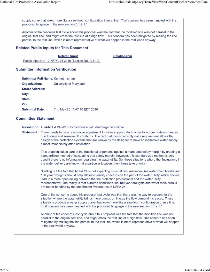
supply curve that looks more like a saw-tooth configuration than a line. That concern has been handled with the proposed language in the new section 5.1.2.1.1.
Another of the concerns last cycle about this proposal was the fact that the modified line was not parallel to the original test line, and might cross the test line at a high flow. This concern has been mitigated by making the line parallel to the test line, which is more representative of what will happen in the real world anyway.
Related Public Inputs for This Document
Related Input Relationship
Public Input No. 12-NFPA 24-2016 [Section No. A.5.1.2]
Submitter Information Verification
Submitter Full Name: Kenneth Isman
Organization: University of Maryland
Street Address:
City:
State:
Zip:
Submittal Date: Thu May 26 11:47:10 EDT 2016
Committee Statement
Resolution: CI-4-NFPA 24-2016 To coordinate with discharge committee.
Statement: There needs to be a reasonable adjustment to water supply data in order to accommodate changesdue to daily and seasonal fluctuations. The fact that this is currently not a requirement allows thedesign of fire protection systems that are known by the designer to have an ineffective water supplyalmost immediately after installation.
This proposal takes care of the traditional arguments against a mandated safety margin by creating astandardized method of calculating that safety margin; however, this standardized method is onlyused if there is no information regarding the water utility. So, those situations where the fluctuations inthe water delivery are known at a particular location, then these take priority.
Spelling out the fact that NFPA 24 is not expecting unusual circumstances like water main breaks and100 year droughts should help alleviate liability concerns on the part of the water utility, which shouldlead to a more open dialog between the fire protection professional and the water utilityrepresentative. The reality is that extreme conditions like 100 year droughts and water main breaksare better handled by the Impairment Procedures of NFPA 25.
One of the concerns about this proposal last cycle was that there was no way to account for thesituation where the water utility brings more pumps on line as the flow demand increases. Thesesituations produce a water supply curve that looks more like a saw-tooth configuration than a line.That concern has been handled with the proposed language in the new section 5.1.2.1.1.
Another of the concerns last cycle about this proposal was the fact that the modified line was notparallel to the original test line, and might cross the test line at a high flow. This concern has beenmitigated by making the line parallel to the test line, which is more representative of what will happenin the real world anyway.
National Fire Protection Association Report http://submittals.nfpa.org/TerraViewWeb/ContentFetcher?commentPara...
9 of 51 11/4/2016 7:43 AM

Water Supply Adjustment Proposals Put Together Insert new sections as follows: 5.1.2.1 Where a waterflow test was conducted, the volume and pressure available for use for a fire protection system shall be determined from either 5.1.2.1.1 or 5.1.2.1.2. 5.1.2.1.1* Knowledge of the water supply and engineering judgment taking into account reasonable daily and seasonal fluctuations not extreme conditions. 5.1.2.1.2* Use of the following formula:
LR
SR PQ
QPPP
85.1
P = The pressure available from the water supply to use for a fire protection system that will be calculated for a given flow (Q) Q = The flow that will be used to calculate the available pressure from the water supply. PR = The residual pressure measured during the waterflow test while the flow QR was discharging from the water supply. PS = The static pressure measured during the waterflow test. QR = The flow discharging from the water supply when PR was measured. PL = The expected low static pressure at the location of the test results accounting for daily and seasonal fluctuations (not extreme conditions) obtained from the water utility. Where the water authority does not provide PL, see 24.2.2.2.1.3.
5.1.2.1.3 Where the water authority does not provide a value for PL, the value of PL shall be calculated from the following formula:
PL = PS – 10 psi A.5.1.2 An adjustment to the waterflow test data to account for the following should be made, as appropriate: (1) Daily and seasonal fluctuations (2) Possible interruption by flood or ice conditions (3) Large simultaneous industrial use (4) Future demand on the water supply system (5) Other conditions that could affect the water supply

A.5.1.2.1.1 The purpose of the adjustment is to take into account reasonable daily and seasonal variations in the water supply, which are easily predicted and tracked by a water utility. It is not the intent to use this section to account for unusual conditions such as 100 year droughts or water main breaks. These unusual conditions are handled through the Impairment Procedures of NFPA 25 and should not be considered when determining the ability of a water supply to meet the demand of a fire protection system under more normal circumstances. A.5.1.2.1.2 Consider the following example. A waterflow test is conducted at a location where a city water main is going to be tapped for a new sprinkler system. During the test, the static pressure is measured at 70 psi, the residual pressure is measured at 50 psi while 1300 gpm was discharging from a nearby hydrant. The water utility is contacted and they indicate that a reasonable low static pressure accounting for typical daily and seasonal fluctuations in this area is 55 psi. The equation that describes the water supply available for a fire sprinkler system would be:
551300
705085.1
QP
There are two ways to use this formula. One would be to assume two different values for Q, calculate P and then draw a graph on log 1.85 paper. Any fire sprinkler system demand falling on or below the line on this graph would be acceptable in accordance with NFPA 13 to work with this water supply. In this case, the two easiest flows to pick for Q would be 0 and 1300 gpm. When Q = 0, P is simply 55 psi. When Q = 1300 gpm, P = 35 psi. These two points can be plotted on log 1.85 paper as shown in Figure A.5.1.2.1.2. The second way to use this formula would be to calculate the fire protection system and determine the flow necessary to make the system work. Plug this flow into the formula above and see what the available pressure from the water supply will be at that flow. For example, if a sprinkler system connected to this water supply had a demand of 580 gpm, the available pressure from the water supply would be:
551300
5807050
85.1
P
P = (-20)(0.225) + 55
P = 50.5 psi
So, as long as the sprinkler system has a pressure demand less than or equal to 50.5 psi, it will work with this water supply.

Figure A.5.1.2.1.2 Available Water Supply Curve for Example in Section A.5.1.2.1.2
Sprinkler system demand can be anywhere in shaded region

Public Input No. 16-NFPA 24-2016 [ Section No. 5.1.2 ]
5.1.2*
The volume flow and pressure of a public water supply shall be determined from waterflow test data orother approved method.
Statement of Problem and Substantiation for Public Input
The flow (volume rate), typically measured or calculated in gallons/minute, is required to be determined of a public water supply, not the volume (gallons).
Submitter Information Verification
Submitter Full Name: James Richardson
Organization: Lisle Woodridge Fire District
Street Address:
City:
State:
Zip:
Submittal Date: Fri Jun 03 16:49:41 EDT 2016
Committee Statement
Resolution: FR-7-NFPA 24-2016
Statement: The flow (volume rate), typically measured or calculated in gallons/minute, is required to bedetermined of a public water supply, not the volume (gallons).
National Fire Protection Association Report http://submittals.nfpa.org/TerraViewWeb/ContentFetcher?commentPara...
10 of 51 11/4/2016 7:43 AM

Public Input No. 30-NFPA 24-2016 [ Section No. 6.1.1.4 ]
6.1.1.4 *
A new connection to a municipal water supply shall be permitted to utilize a nonlisted, nonindicatingvalve, including a T-wrench as part of a tapping assembly, shall be permitted .
6.1.1.4.1
For new installations, where more than one nonindicating underground gate valve is installed in a watersystem, all underground gate valves shall be of the same opening direction.
Statement of Problem and Substantiation for Public Input
This proposal is offered to provide better clarification to the type of valves is to be installed. Without the reference to a new connection to a municipal water supply, the current text in the 2016 edition of the standard suggests that a nonlisted, nonindicating valve is permitted at any time, as long as it is part of a tapping assembly.
Submitter Information Verification
Submitter Full Name: Larry Keeping
Organization: PLC Fire Safety Solutions
Street Address:
City:
State:
Zip:
Submittal Date: Tue Jun 28 23:42:57 EDT 2016
Committee Statement
Resolution: FR-6-NFPA 24-2016
Statement: This proposal is offered to provide clarification of the type of valves to be installed. Without thereference to a new connection to a municipal water supply, the current text in the 2016 edition of thestandard suggests that a nonlisted, nonindicating valve is permitted at any time, as long as it is part ofa tapping assembly.
National Fire Protection Association Report http://submittals.nfpa.org/TerraViewWeb/ContentFetcher?commentPara...
11 of 51 11/4/2016 7:43 AM

Public Input No. 13-NFPA 24-2016 [ Section No. 7.1.1.1 ]
7.1.1.1
The connection from the hydrant to the main shall not be less than 6 in on a grid system with crossconnections no greater than 600 feet . (150) (nominal). If installed on a end line the minimum size shall be8 inch
Statement of Problem and Substantiation for Public Input
AWWA Manual M31, "Distribution System Requirements for Fire Protection" states under a table heading "Typical Minimum Values", for "Smallest pipes in networks" as "6 in.", and for "Smallest branching pipes (dead ends) "8 in.". This information was found on the internet
Submitter Information Verification
Submitter Full Name: Ed White
Organization: Greenville Fire Rescue
Street Address:
City:
State:
Zip:
Submittal Date: Mon May 30 01:14:15 EDT 2016
Committee Statement
Resolution: NFPA 24 limits minimum size to 6" if caluculations can be provided that support use of smaller than 8"piping, there is no reason to mandate 8" piping.
National Fire Protection Association Report http://submittals.nfpa.org/TerraViewWeb/ContentFetcher?commentPara...
12 of 51 11/4/2016 7:43 AM

Public Input No. 31-NFPA 24-2016 [ Section No. 7.1.1.2 ]
7.1.1.2
A control valve in accordance with Section 6.1 shall be installed in each hydrant connection.
7.1.1.2.1
Valves required by 7.1.1.2 shall be installed within 20 ft (6.1 m) of the hydrant.
7.1.1.2.1.1
Valves shall be clearly identified and kept free of obstructions.
7.1.1.2.2
Where valves cannot be located in accordance with 7.1.1.2.1, valve locations shall be permitted whereapproved by the AHJ.
Statement of Problem and Substantiation for Public Input
This proposal is offered to provide clarification to the type of valve is to be installed to control a hydrant. Without the reference to Section 6.1, the current edition of the standard does not even specify that the valve be listed.
Additionally, a separate proposal has also been offered, to change the illustrations of the hydrant connection valves Figure A.7.3.1(a) and Figure A.7.3.1(b) from the nonindicating type to the post indicator type, because as per the charging statement Section 6.1.1, indicating type valves are called for, whereas the nonindicating type are only allowed under 6.1.1.3 with the permission of the AHJ.
Submitter Information Verification
Submitter Full Name: Larry Keeping
Organization: PLC Fire Safety Solutions
Street Address:
City:
State:
Zip:
Submittal Date: Tue Jun 28 23:45:56 EDT 2016
Committee Statement
Resolution:
National Fire Protection Association Report http://submittals.nfpa.org/TerraViewWeb/ContentFetcher?commentPara...
13 of 51 11/4/2016 7:43 AM

Public Input No. 32-NFPA 24-2016 [ Section No. 7.3.2.1 ]
7.3.2.1
Where soil is of such a nature that the hydrants will not drain properly with the arrangement specified in7.3.1 2 , or where groundwater stands at levels above that of the drain, the hydrant drain shall be pluggedbefore installation.
7.3.2.1.1 *
Hydrants with drain plugs shall be marked to indicate the need for pumping out after usage.
Statement of Problem and Substantiation for Public Input
Editorial correction. 7.3.1 speaks on the support of hydrants, whereas it is 7.3.2 that deals with drainage preparation.
Submitter Information Verification
Submitter Full Name: Larry Keeping
Organization: PLC Fire Safety Solutions
Street Address:
City:
State:
Zip:
Submittal Date: Tue Jun 28 23:49:02 EDT 2016
Committee Statement
Resolution: FR-9-NFPA 24-2016
Statement: Editorial correction. 7.3.1 speaks on the support of hydrants, whereas it is 7.3.2 that deals withdrainage preparation.
National Fire Protection Association Report http://submittals.nfpa.org/TerraViewWeb/ContentFetcher?commentPara...
14 of 51 11/4/2016 7:43 AM

Public Input No. 24-NFPA 24-2016 [ Section No. 10.1.1.1 ]
National Fire Protection Association Report http://submittals.nfpa.org/TerraViewWeb/ContentFetcher?commentPara...
15 of 51 11/4/2016 7:43 AM

10.1.1.1 Listing.
National Fire Protection Association Report http://submittals.nfpa.org/TerraViewWeb/ContentFetcher?commentPara...
16 of 51 11/4/2016 7:43 AM

Piping manufactured in accordance with Table 10.1.1.1 shall be permitted to be used..
Table 10.1.1.1 Manufacturing Standards for Underground Pipe
Materials and Dimensions Standard
Ductile Iron
Cement Mortar Lining for Ductile Iron Pipe and Fittings for WaterAWWAC104
Polyethylene Encasement for Ductile Iron Pipe SystemsAWWAC105
Rubber-Gasket Joints for Ductile Iron Pressure Pipe and Fittings AWWA C111
Flanged Ductile Iron Pipe with Ductile Iron or Gray Iron Threaded FlangesAWWAC115
Thickness Design of Ductile Iron PipeAWWAC150
Ductile Iron Pipe, Centrifugally Cast for WaterAWWAC151
Standard for the Installation of Ductile Iron Water Mains and Their AppurtenancesAWWAC600
Steel
Steel Water Pipe 6 in. and LargerAWWAC200
Coal-Tar Protective Coatings and Linings for Steel Water Pipelines Enamel and Tape — HotApplied
AWWAC203
Cement-Mortar Protective Lining and Coating for Steel Water Pipe 4 in. and Larger — ShopApplied
AWWAC205
Field Welding of Steel Water PipeAWWAC206
Steel Pipe Flanges for Waterworks Service — Sizes 4 in. Through 144 in.AWWAC207
Dimensions for Fabricated Steel Water Pipe FittingsAWWAC208
A Guide for Steel Pipe Design and Installation AWWA M11
Concrete
Reinforced Concrete Pressure Pipe, Steel-Cylinder TypeAWWAC300
Prestressed Concrete Pressure Pipe, Steel-Cylinder TypeAWWAC301
Reinforced Concrete Pressure Pipe, Non-Cylinder TypeAWWAC302
Reinforced Concrete Pressure Pipe, Steel-Cylinder Type, PretensionedAWWAC303
Standard for Asbestos-Cement Distribution Pipe, 4 in. Through 16 in., for Water DistributionSystems
AWWAC400
Cement-Mortar Lining of Water Pipe Lines 4 in. and Larger — in PlaceAWWAC602
Plastic
Polyvinyl Chloride (PVC) Pressure Pipe, 4 in. Through 12 in., for Water DistributionAWWAC900
Polyvinyl Chloride (PVC) Pressure Pipe, 14 in. Through 48 in., for Water DistributionAWWAC905
National Fire Protection Association Report http://submittals.nfpa.org/TerraViewWeb/ContentFetcher?commentPara...
17 of 51 11/4/2016 7:43 AM

Materials and Dimensions Standard
Polyethylene (PE) Pressure Pipe and Fittings, 4 in. (100 mm) Through 63 in. (1575 mm) forWater Distribution
AWWAC906
Molecularly Oriented Polyvinyl Chloride (PVCO) 4 in. Through 12 in. (100 mm Through600 mm) for Water Distribution
AWWAC909
Brass
Specification for Seamless Red Brass Pipe ASTM B43
Copper
Specification for Seamless Copper Tube ASTM B75
Specification for Seamless Copper Water Tube ASTM B88
Requirements for Wrought Seamless Copper and Copper-Alloy Tube ASTM B251
Statement of Problem and Substantiation for Public Input
Related Public Inputs for This Document:Public Input No. 25-NFPA 24-2016 [ Section No. 2.3.3 ]Public Input No. 376-NFPA 13-2016 [ Section No. 2.3.6 ]Public Input No. 375-NFPA 13-2016 [ Section No. 10.1.1.1 ]
The Resolution for the “Public Comment No. 2-NFPA 24-2014 [ Section No. 10.1.1.1 ]” says (page 25/35 of file “24_A2015_SD_PCStatements.pdf”):
“The document has required steel piping for general underground service to be listed for the last few editions.”
The document has required steel piping for general underground service to be listed in the NFPA 13/24-2002/7/10/13 editions.The document has required steel piping for general underground service to not be nonlisted in the NFPA 13/24-2002/7/10/13 editions.
The document has required steel piping for other than general underground service to be listed or to be nonlisted in the NFPA 13-2002/7/10/13 and NFPA 24-2002/10/13 editions.The current NFPA 13/24-2016 edition requires steel piping for other than general underground service to be listed.
This Public Input restores the document to the requirement in the NFPA 13-2002/7/10/13 and NFPA 24-2002/10/13 editions: steel piping for other than general underground service is required to be listed (through 10.1.1.2) or to be nonlisted (through Table 10.1.1.1) .
Related Public Inputs for This Document
Related Input Relationship
Public Input No. 25-NFPA 24-2016 [Section No. 2.3.3]
Submitter Information Verification
Submitter Full Name: Ariel Carp
Organization: On my behalf
Street Address:
City:
State:
Zip:
Submittal Date: Sun Jun 26 10:01:54 EDT 2016
Committee Statement
National Fire Protection Association Report http://submittals.nfpa.org/TerraViewWeb/ContentFetcher?commentPara...
18 of 51 11/4/2016 7:43 AM

Resolution: Steel piping used for underground needs to be listed due to issues surrounding corrosion.
National Fire Protection Association Report http://submittals.nfpa.org/TerraViewWeb/ContentFetcher?commentPara...
19 of 51 11/4/2016 7:43 AM

Public Input No. 17-NFPA 24-2016 [ Section No. 10.1.4 ]
10.1.4
Where piping installed in a private fire service main must be installed above grade, the piping materialsshall conform to NFPA 13.
10.1.4.1 * *
Underground piping shall be permitted to extend into the building through the slab or wall not more than
24 in
24 in . (
600 mm
600 mm ).
Statement of Problem and Substantiation for Public Input
Chapter 10 applies to private fire service mains installed below grade. Chapter 12 applies to private fire service mains installed above grade.
Submitter Information Verification
Submitter Full Name: James Richardson
Organization: Lisle Woodridge Fire District
Street Address:
City:
State:
Zip:
Submittal Date: Fri Jun 03 17:18:57 EDT 2016
Committee Statement
Resolution: FR-22-NFPA 24-2016
Statement: Chapter 10 applies to private fire service mains installed below grade. Chapter 12 applies to privatefire service mains installed above grade. Renumber annex section accordingly.
National Fire Protection Association Report http://submittals.nfpa.org/TerraViewWeb/ContentFetcher?commentPara...
20 of 51 11/4/2016 7:43 AM

Public Input No. 33-NFPA 24-2016 [ Section No. 10.3 ]
10.3 Connection of Pipe, Fittings, and Appurtenances.
10.3.1 *
Connection of all fittings and appurtenances to piping shall be in accordance with Section 10.3.
10.3.2 Threaded Pipe and Fittings.
Connections of pipe and fittings indicated in Table 10.1.1.1 and Table 10.2.1.1 shall be in accordance withthe referenced standard in the table.
10.3.3 Listed Connections.
Connections utilizing listed products shall be in accordance with the listing limitations and themanufacturer’s installation instructions.
10.3.3.1
Where listing limitations or installation instructions differ from the requirements of this standard, the listinglimitations and installation instructions shall apply.
10.3.4 Threaded Pipe and Fittings.
Where pipe, fittings or appurtenances are connected using threads, all threads shall be in accordance withANSI/ASME B1.20.1.
10.3.5 Grooved Connections.
Where pipe, fittings, or appurtenances are connected using grooves, they shall be connected inaccordance with 10.3.5.1 through 10.3.5.3.
10.3.5.1
Pipe, fittings, and appurtenances to be joined with grooved couplings shall contain cut, rolled, or castgrooves that are dimensionally compatible with the couplings.
10.3.5.2
Pipe, fittings, and appurtenances that are connected with grooved couplings and are part of a listedassembly shall be permitted to be used.
10.3.5.3 *
Pipe joined with grooved fittings shall be joined by a listed combination of fittings, gaskets, and grooves.
10.3.6
All joints for the connection of copper tube shall be brazed or joined using pressure fittings as specified inTable 10.2.1.1.
Statement of Problem and Substantiation for Public Input
Editorial correction. 10.3.2 speaks to all of the various types of connections, whereas it is 10.3.4 that specifically deals with pipe threads.
Submitter Information Verification
Submitter Full Name: Larry Keeping
Organization: PLC Fire Safety Solutions
Street Address:
City:
State:
National Fire Protection Association Report http://submittals.nfpa.org/TerraViewWeb/ContentFetcher?commentPara...
21 of 51 11/4/2016 7:43 AM

Zip:
Submittal Date: Tue Jun 28 23:51:39 EDT 2016
Committee Statement
Resolution: FR-10-NFPA 24-2016
Statement: Editorial correction. 10.3.2 speaks to all of the various types of connections, whereas it is 10.3.4 thatspecifically deals with pipe threads.
National Fire Protection Association Report http://submittals.nfpa.org/TerraViewWeb/ContentFetcher?commentPara...
22 of 51 11/4/2016 7:43 AM

Public Input No. 19-NFPA 24-2016 [ Sections 10.4.2.1.4, 10.4.2.1.5, 10.4.2.1.6, 10.4.2.1.7 ]
Sections 10.4.2.1.4, 10.4.2.1.5, 10.4.2.1.6, 10.4.2.1.7
10.4.2.1.4
Where private fire service mains are installed above ground, they shall be protected from freezing inaccordance with NFPA 13.
10.4.2.1.5
Private fire service mains installed in water raceways or shallow streams shall be installed so that the pipingwill remain in the running water throughout the year.
10.4.2.1.6 5
Where piping is installed adjacent to a vertical face, it shall be installed from the vertical face at the samedistance as if the piping were buried.
10.4.2.1.7 6
Protection of private fire service mains from freezing using heat tracing shall be permitted when the heattracing is specifically listed for underground use.
10.4.2.1.7.1
Heat tracing not listed for underground use shall be permitted when piping is installed
Where an underground fire service main extends into a building in accordance with 10.1.4 , the exposedpipe shall be protected from freezing in accordance with 12 .2.3.
Statement of Problem and Substantiation for Public Input
Chapter 10 is underground requirements. Chapter 12 is aboveground requirements.
Submitter Information Verification
Submitter Full Name: James Richardson
Organization: Lisle Woodridge Fire District
Street Address:
City:
State:
Zip:
Submittal Date: Fri Jun 03 23:01:26 EDT 2016
Committee Statement
Resolution: Guidance for aboveground piping is needed.
National Fire Protection Association Report http://submittals.nfpa.org/TerraViewWeb/ContentFetcher?commentPara...
23 of 51 11/4/2016 7:43 AM

Public Input No. 15-NFPA 24-2016 [ Section No. 10.4.2.2 [Excluding any Sub-Sections] ]
The depth of cover for private fire service mains and their appurtenances to protect against mechanicaldamage shall be in accordance with 10.4.2.2.3 .
Statement of Problem and Substantiation for Public Input
Correction of typo. The entire section of 10.4.2.2 applies to the protection of piping from mechanical damage, not just section 10.4.2.2.3.
Submitter Information Verification
Submitter Full Name: James Richardson
Organization: Lisle Woodridge Fire District
Street Address:
City:
State:
Zip:
Submittal Date: Fri Jun 03 16:37:00 EDT 2016
Committee Statement
Resolution: FR-11-NFPA 24-2016
Statement: Correction of typo. The entire section of 10.4.2.2 applies to the protection of piping from mechanicaldamage, not just section 10.4.2.2.3.
National Fire Protection Association Report http://submittals.nfpa.org/TerraViewWeb/ContentFetcher?commentPara...
24 of 51 11/4/2016 7:43 AM

Public Input No. 20-NFPA 24-2016 [ Section No. 10.4.2.2.6 ]
10.4.2.2.6
Where private fire service mains are installed above ground, they shall be protected with bollards or othermeans as approved by the AHJ when subject to mechanical damage.
Statement of Problem and Substantiation for Public Input
Chapter 10 is underground requirements. Chapter 12 is aboveground requirements. Relocate section to Chapter 12.
Submitter Information Verification
Submitter Full Name: James Richardson
Organization: Lisle Woodridge Fire District
Street Address:
City:
State:
Zip:
Submittal Date: Fri Jun 03 23:11:53 EDT 2016
Committee Statement
Resolution: Guidance on protection of pipe is needed.
National Fire Protection Association Report http://submittals.nfpa.org/TerraViewWeb/ContentFetcher?commentPara...
25 of 51 11/4/2016 7:43 AM

Public Input No. 14-NFPA 24-2016 [ Section No. 10.4.3.1.1 ]
10.4.3.1.1*
Pipe joints and fittings shall not be located directly under foundation fittings footings .
Statement of Problem and Substantiation for Public Input
Change of language to be consistent with intent of section and Figure A.10.4.3.1.1.
Submitter Information Verification
Submitter Full Name: James Richardson
Organization: Lisle Woodridge Fire District
Street Address:
City:
State:
Zip:
Submittal Date: Fri Jun 03 16:29:56 EDT 2016
Committee Statement
Resolution: See FR based on PI 34.
National Fire Protection Association Report http://submittals.nfpa.org/TerraViewWeb/ContentFetcher?commentPara...
26 of 51 11/4/2016 7:43 AM

Public Input No. 34-NFPA 24-2016 [ Section No. 10.4.3.1.1 ]
10.4.3.1.1 *
Pipe joints shall not be located directly under foundation fittings footings .
Statement of Problem and Substantiation for Public Input
Editorial Correction.
Submitter Information Verification
Submitter Full Name: Larry Keeping
Organization: PLC Fire Safety Solutions
Street Address:
City:
State:
Zip:
Submittal Date: Tue Jun 28 23:54:15 EDT 2016
Committee Statement
Resolution: FR-12-NFPA 24-2016
Statement: Editorial Correction.
National Fire Protection Association Report http://submittals.nfpa.org/TerraViewWeb/ContentFetcher?commentPara...
27 of 51 11/4/2016 7:43 AM

Public Input No. 26-NFPA 24-2016 [ Section No. 10.4.3.2 ]
10.4.3.2 *
Where approved, private fire service mains supplying systems within the building shall be permitted toextend more than 10 ft (3.0 m) under the building when all the requirements of 10.4.3.2.1 , through10.4.3.2.4 are met.
10.4.3.2.1
Where the piping is installed under the building, all foundations or footers over the private fire service mainshall be arched to create a minimum of 24 in (600 mm) clearance.
10.4.3.2.2
It shall be acceptable to install the piping in covered trenches where the trenches are accessible fromwithin the building.
10.4.3.2.3
All joints shall be mechanically restrained.
10.4.3.2.4
A valve shall be installed before the piping enters under the building and within 24 in. (600 mm) of wherethe piping enters the building.
Additional Proposed Changes
File Name Description Approved
Trench_Task_Group.docx Trench Task Group Work
Statement of Problem and Substantiation for Public Input
During the last revision, a task group was formed to work on trench language for piping running under buildings. During the second draft the task group proposed language to the committee and the language was accepted. However, the first draft language was published. Attached is the language that the task group created.
Submitter Information Verification
Submitter Full Name: Peter Schwab
Organization: Wayne Automatic Fire Sprinkler
Street Address:
City:
State:
Zip:
Submittal Date: Tue Jun 28 12:06:54 EDT 2016
Committee Statement
Resolution: FR-14-NFPA 24-2016
Statement: During the last revision, a task group was formed to work on trench language for piping running underbuildings. During the second draft the task group proposed language to the committee and thelanguage was accepted. However, the first draft language was published. Attached is the languagethat the task group created.
National Fire Protection Association Report http://submittals.nfpa.org/TerraViewWeb/ContentFetcher?commentPara...
28 of 51 11/4/2016 7:43 AM

10.4.3.2 Private fire service mains shall not be permitted to extend more than 10 ft (3 m) under the building except as allowed in 10.4.3.2.1. 10.4.3.2.1 Where private fire service mains extend more than 10 ft (3 m) into the building, they shall be run in a trench. 10.4.3.2.1.1 The trench shall be accessible from within the building. A.10.4.3.2.1.1 A grate or steel plate are common methods of accessing the trench. 10.4.3.2.1.2 The trench shall have rigid walls and a base. 10.4.3.2.1.3 The trench shall be constructed of non‐combustible materials. 10.4.3.2.1.4 Provisions for draining water shall be provided for the trench. A.10.4.3.2.1.4 The intent of this requirement is to prevent the piping from being exposed to standing water. Draining can be accomplished by providing a floor drain, sloping of the trench, or other approved method. 10.4.3.2.1.5 Where the piping in the trench is installed under foundations or footers, the foundation or footer shall be arched to create a minimum of 24 in (610 mm) clearance. 10.4.3.2.1.5.1 Where acceptable to the Authority Having Jurisdiction, pipe sleeves shall be permitted to be used. 10.4.3.2.2 Piping in the trench shall be permitted to be in accordance with 10.1.1. 10.4.3.2.2.1 Where the trench is entirely of concrete construction, aboveground piping in accordance with NFPA 13 shall be permitted to be used. 10.4.3.2.2.2 Where piping installed in the trench is in accordance with 10.1.1, all joints shall be restrained in accordance with 10.6.2 or 10.6.3. 10.4.3.2.3 Where piping is installed in a trench as allowed by 10.4.3.2.1, a valve shall be provided where the underground piping enters the trench.

A.10.4.3.2.3 It is the intent of this section to require a valve at each point where the pipe enters the trench when the trench traverses the entire building. Generally if the piping terminates at a point within the building usually a valve is provided at a riser, allowing isolation of the pipe section in the trench.

Public Input No. 27-NFPA 24-2016 [ Section No. 10.9.3 ]
10.9.3
In the absence of specific guidleines, the maximum allowable particle size for backfill within 1' of the pipeshould be 3/4". Nominal pipe sizes of 4" or smaller should not exceed 1/2" maximum particle size. Rockslarger than 1-1/2" shall not be used for backfill.
Statement of Problem and Substantiation for Public Input
The comment of Rocks shall not be used for backfill seems to be vague and without definition. I have proposed language that was borrowed from Amster Howard's book Pipeline Installation 2.0. I added the 1/2" size limitation as that is a recommendation for HDPE pipe and feel it may be appropriate for other piping materials.
Submitter Information Verification
Submitter Full Name: Donald McGriff
Organization: Isco Industries
Street Address:
City:
State:
Zip:
Submittal Date: Tue Jun 28 12:51:37 EDT 2016
Committee Statement
Resolution: PI contained unenforceable language however has technical merit. A Task Group has been formed tofurther study the issue.
National Fire Protection Association Report http://submittals.nfpa.org/TerraViewWeb/ContentFetcher?commentPara...
29 of 51 11/4/2016 7:43 AM

Public Input No. 4-NFPA 24-2016 [ Section No. 10.10.1 ]
10.10.1 Approval of Underground Piping.
The installing contractor shall be responsible for the following:
(1) Notifying the AHJ and the owner's representative of the time and date testing is to be performed
(2) Performing all required acceptance tests
(3) Completing and signing the contractor's material and test certificate(s) shown in Figure 10.10.1 Revise Figure 10.10. 1 to remove the use of a burlap bag while flushing.
Figure 10.10.1 Sample of Contractor's Material and Test Certificate for Underground Piping.
Statement of Problem and Substantiation for Public Input
The figure calls out the use of a burlap bag during flushing in the sample and as such becomes a defacto requirement. However, the use of this bag is not discussed in the body of the standard and should not be treated as a requirement. Other methods of inspecting for debris can be used.
Submitter Information Verification
Submitter Full Name: Charles McKnight
Organization: Bechtel National, Inc.
Street Address:
City:
State:
Zip:
Submittal Date: Mon Jan 18 15:08:01 EST 2016
Committee Statement
National Fire Protection Association Report http://submittals.nfpa.org/TerraViewWeb/ContentFetcher?commentPara...
30 of 51 11/4/2016 7:43 AM

Resolution: FR-15-NFPA 24-2016
Statement: Change the test certificate under Instructions to read:
"Have copies of appropriate instructions and care and maintenance charts been provided to theowner or owner's representative."
Some AHJ's have been requiring that a copy NFPA 25 be left at each building of apartmentcomplexes.
Revise Figure 10.10.1 to remove the use of a burlap bag while flushing. (remove "in burlap bags"from flushing section on form. The revised language will read as follows:
Flushing: Flow the required rate until water is clear as indicated by no collection of foreign material atoutlets such as hydrants and blow-offs. Flush at one of the flow rates as specified in 10.10.2.1.3.
National Fire Protection Association Report http://submittals.nfpa.org/TerraViewWeb/ContentFetcher?commentPara...
31 of 51 11/4/2016 7:43 AM

Public Input No. 5-NFPA 24-2016 [ Section No. 10.10.1 ]
National Fire Protection Association Report http://submittals.nfpa.org/TerraViewWeb/ContentFetcher?commentPara...
32 of 51 11/4/2016 7:43 AM

10.10.1 Approval of Underground Piping.
The installing contractor shall be responsible for the following:
(1) Notifying the AHJ and the owner's representative of the time and date testing is to be performed
(2) Performing all required acceptance tests
(3) Completing and signing the contractor's material and test certificate(s) shown in Figure 10.10.1
Figure 10.10.1 Sample of Contractor's Material and Test Certificate for Underground Piping.
Statement of Problem and Substantiation for Public Input
Change the test certificate to read "Have copies of appropriate instructions and care and maintenance charts been provided to the owner or owner's representative." Some AHJ's have been requiring that a copy NFPA 25 be left at
National Fire Protection Association Report http://submittals.nfpa.org/TerraViewWeb/ContentFetcher?commentPara...
33 of 51 11/4/2016 7:43 AM

each building of apartment complexes.
Submitter Information Verification
Submitter Full Name: Peter Schwab
Organization: Wayne Automatic Fire Sprinkler
Street Address:
City:
State:
Zip:
Submittal Date: Sun Feb 14 15:46:24 EST 2016
Committee Statement
Resolution: FR-15-NFPA 24-2016
Statement: Change the test certificate under Instructions to read:
"Have copies of appropriate instructions and care and maintenance charts been provided to theowner or owner's representative."
Some AHJ's have been requiring that a copy NFPA 25 be left at each building of apartmentcomplexes.
Revise Figure 10.10.1 to remove the use of a burlap bag while flushing. (remove "in burlap bags"from flushing section on form. The revised language will read as follows:
Flushing: Flow the required rate until water is clear as indicated by no collection of foreign material atoutlets such as hydrants and blow-offs. Flush at one of the flow rates as specified in 10.10.2.1.3.
National Fire Protection Association Report http://submittals.nfpa.org/TerraViewWeb/ContentFetcher?commentPara...
34 of 51 11/4/2016 7:43 AM
Public Input No. 22-NFPA 24-2016 [ New Section after 10.10.2.1.3.1 ]
10.10.2.1.3.2
A means shall be provided to verify that the flow rate required by 10.10.2.1.3 or 10.10.2.1.3.1 was achievedduring the flushing operation.
Statement of Problem and Substantiation for Public Input
There is currently no requirement for verification that the required flow was achieved during the flush test and therefore, when the test is performed, it is unknown whether or not the correct flow was achieved.
Submitter Information Verification
Submitter Full Name: James Richardson
Organization: Lisle Woodridge Fire District
Street Address:
City:
State:
Zip:
Submittal Date: Fri Jun 03 23:19:03 EDT 2016
Committee Statement
Resolution: Options are already provided to allow for flushing a system i.e.: opening the valve completely ormeasuring flow.
National Fire Protection Association Report http://submittals.nfpa.org/TerraViewWeb/ContentFetcher?commentPara...
35 of 51 11/4/2016 7:43 AM

Public Input No. 10-NFPA 24-2016 [ Section No. 10.10.2.2.1 ]
10.10.2.2.1 *
All piping and attached appurtenances subjected to system working pressure shall be hydrostatically testedat gauge pressure of 200 psi (13.8 bar) or 50 psi (3.4 bar) in excess of the system working pressure,whichever is greater, and shall maintain that pressure at gauge pressure of ±5 psi (0.34 bar) for 2 hours. Aternatively, pressure testing of Polyethylene piping may be conducted in accordance with therequirements and recommendations of ASTM F 2164(Field Leak Testing of Polyethylene Pressure PipingSystems Using Hydrostatic Pressure).
Statement of Problem and Substantiation for Public Input
due to the viscoelastic stress relieving nature of polyethylene pipe, the actual loss as shown by gauge pressure may fall below the allowable listed in 10.10.2.2.1 as currently written. The proposed addition of the ASTM standard would allow for a testing protocol that is commonly used with HDPE piping systems. This change may be better suited as a new subparagraph to section 10.10.2.3 instead of where I proposed placement.
Submitter Information Verification
Submitter Full Name: Donald McGriff
Organization: Isco Industries
Street Address:
City:
State:
Zip:
Submittal Date: Mon May 02 14:23:59 EDT 2016
Committee Statement
Resolution: FR-16-NFPA 24-2016
Statement: Alternate test methods should be permitted but not required.
National Fire Protection Association Report http://submittals.nfpa.org/TerraViewWeb/ContentFetcher?commentPara...
36 of 51 11/4/2016 7:43 AM

Public Input No. 21-NFPA 24-2016 [ New Section after 12.2.6 ]
12.2.7
Aboveground private fire service mains shall be protected with bollards or other means as approved by theAHJ when subject to mechanical damage.
Statement of Problem and Substantiation for Public Input
Relocation of section 10.4.2.2.6 to chapter 12 for aboveground requirements.
Submitter Information Verification
Submitter Full Name: James Richardson
Organization: Lisle Woodridge Fire District
Street Address:
City:
State:
Zip:
Submittal Date: Fri Jun 03 23:13:10 EDT 2016
Committee Statement
Resolution: FR-24-NFPA 24-2016
Statement: Relocation of section 10.4.2.2.6 to chapter 12 for aboveground requirements.
National Fire Protection Association Report http://submittals.nfpa.org/TerraViewWeb/ContentFetcher?commentPara...
37 of 51 11/4/2016 7:43 AM

Public Input No. 12-NFPA 24-2016 [ Section No. A.5.1.2 ]
National Fire Protection Association Report http://submittals.nfpa.org/TerraViewWeb/ContentFetcher?commentPara...
38 of 51 11/4/2016 7:43 AM

A.5.1.2
An adjustment to the waterflow test data to account for the following should be made, as appropriate:
(1) Daily and seasonal fluctuations
(2) Possible interruption by flood or ice conditions
(3) Large simultaneous industrial use
(4) Future demand on the water supply system
(5) Other conditions that could affect the water supply
.1.1 The purpose of the adjustment is to take into account reasonable daily and seasonal variations in thewater supply, which are easily predicted and tracked by a water utility. It is not the intent to use thissection to account for unusual conditions such as 100 year droughts or water main breaks. These unusualconditions are handled through the Impairment Procedures of NFPA 25 and should not be consideredwhen determining the ability of a water supply to meet the demand of a fire protection system under morenormal circumstances.
A.5.1.2.1.2 Consider the following example. A waterflow test is conducted at a location where a city watermain is going to be tapped for a new sprinkler system. During the test, the static pressure is measured at70 psi, the residual pressure is measured at 50 psi while 1300 gpm was discharging from a nearbyhydrant. The water utility is contacted and they indicate that a reasonable low static pressure accountingfor typical daily and seasonal fluctuations in this area is 55 psi. The equation that describes the watersupply available for a fire sprinkler system would be:
There are two ways to use this formula. One would be to assume two different values for Q, calculate Pand then draw a graph on log 1.85 paper. Any fire sprinkler system demand falling on or below the line onthis graph would be acceptable in accordance with NFPA 13 to work with this water supply. In this case,the two easiest flows to pick for Q would be 0 and 1300 gpm. When Q = 0, P is simply 55 psi. When Q =1300 gpm, P = 35 psi. These two points can be plotted on log 1.85 paper as shown in Figure A.5.1.2.1.2.
The second way to use this formula would be to calculate the fire protection system and determine the flownecessary to make the system work. Plug this flow into the formula above and see what the availablepressure from the water supply will be at that flow. For example, if a sprinkler system connected to thiswater supply had a demand of 580 gpm, the available pressure from the water supply would be:
P = (-20)(0.225) 55
P = 50.5 psi
So, as long as the sprinkler system has a pressure demand less than or equal to 50.5 psi, it will work withthis water supply.
Sprinkler system demand can be anywhere in shadedregion
FigureA-24-2-2-2-1.tiff
Figure A.5.1.2.1.2 Available Water Supply Curve for Example in Section A.5.1.2.1.2
National Fire Protection Association Report http://submittals.nfpa.org/TerraViewWeb/ContentFetcher?commentPara...
39 of 51 11/4/2016 7:43 AM

Additional Proposed Changes
File Name Description Approved
Safety_Margin_Proposal-NFPA_24.docx
This is what the proposal will look like if both PI's are accepted. Note that this also has the formulas and figures that I could not figure out how to get into Terra View.
Statement of Problem and Substantiation for Public Input
This is the annex companion to the adjustment issues proposed for the body of the standard. The examples are helpful in explaining how to perform the calculations and use the formula.
Related Public Inputs for This Document
Related Input Relationship
Public Input No. 11-NFPA 24-2016 [New Section after 5.1.2]
Submitter Information Verification
Submitter Full Name: Kenneth Isman
Organization: University of Maryland
Street Address:
City:
State:
Zip:
Submittal Date: Thu May 26 11:53:35 EDT 2016
Committee Statement
Resolution: CI-4-NFPA 24-2016 To coordinate with discharge committee.
Statement: There needs to be a reasonable adjustment to water supply data in order to accommodate changesdue to daily and seasonal fluctuations. The fact that this is currently not a requirement allows thedesign of fire protection systems that are known by the designer to have an ineffective water supplyalmost immediately after installation.
This proposal takes care of the traditional arguments against a mandated safety margin by creating astandardized method of calculating that safety margin; however, this standardized method is onlyused if there is no information regarding the water utility. So, those situations where the fluctuations inthe water delivery are known at a particular location, then these take priority.
Spelling out the fact that NFPA 24 is not expecting unusual circumstances like water main breaks and100 year droughts should help alleviate liability concerns on the part of the water utility, which shouldlead to a more open dialog between the fire protection professional and the water utilityrepresentative. The reality is that extreme conditions like 100 year droughts and water main breaksare better handled by the Impairment Procedures of NFPA 25.
One of the concerns about this proposal last cycle was that there was no way to account for thesituation where the water utility brings more pumps on line as the flow demand increases. Thesesituations produce a water supply curve that looks more like a saw-tooth configuration than a line.That concern has been handled with the proposed language in the new section 5.1.2.1.1.
Another of the concerns last cycle about this proposal was the fact that the modified line was notparallel to the original test line, and might cross the test line at a high flow. This concern has beenmitigated by making the line parallel to the test line, which is more representative of what will happenin the real world anyway.
National Fire Protection Association Report http://submittals.nfpa.org/TerraViewWeb/ContentFetcher?commentPara...
40 of 51 11/4/2016 7:43 AM

Water Supply Adjustment Proposals Put Together Insert new sections as follows: 5.1.2.1 Where a waterflow test was conducted, the volume and pressure available for use for a fire protection system shall be determined from either 5.1.2.1.1 or 5.1.2.1.2. 5.1.2.1.1* Knowledge of the water supply and engineering judgment taking into account reasonable daily and seasonal fluctuations not extreme conditions. 5.1.2.1.2* Use of the following formula:
LR
SR PQ
QPPP
85.1
P = The pressure available from the water supply to use for a fire protection system that will be calculated for a given flow (Q) Q = The flow that will be used to calculate the available pressure from the water supply. PR = The residual pressure measured during the waterflow test while the flow QR was discharging from the water supply. PS = The static pressure measured during the waterflow test. QR = The flow discharging from the water supply when PR was measured. PL = The expected low static pressure at the location of the test results accounting for daily and seasonal fluctuations (not extreme conditions) obtained from the water utility. Where the water authority does not provide PL, see 24.2.2.2.1.3.
5.1.2.1.3 Where the water authority does not provide a value for PL, the value of PL shall be calculated from the following formula:
PL = PS – 10 psi A.5.1.2 An adjustment to the waterflow test data to account for the following should be made, as appropriate: (1) Daily and seasonal fluctuations (2) Possible interruption by flood or ice conditions (3) Large simultaneous industrial use (4) Future demand on the water supply system (5) Other conditions that could affect the water supply

A.5.1.2.1.1 The purpose of the adjustment is to take into account reasonable daily and seasonal variations in the water supply, which are easily predicted and tracked by a water utility. It is not the intent to use this section to account for unusual conditions such as 100 year droughts or water main breaks. These unusual conditions are handled through the Impairment Procedures of NFPA 25 and should not be considered when determining the ability of a water supply to meet the demand of a fire protection system under more normal circumstances. A.5.1.2.1.2 Consider the following example. A waterflow test is conducted at a location where a city water main is going to be tapped for a new sprinkler system. During the test, the static pressure is measured at 70 psi, the residual pressure is measured at 50 psi while 1300 gpm was discharging from a nearby hydrant. The water utility is contacted and they indicate that a reasonable low static pressure accounting for typical daily and seasonal fluctuations in this area is 55 psi. The equation that describes the water supply available for a fire sprinkler system would be:
551300
705085.1
QP
There are two ways to use this formula. One would be to assume two different values for Q, calculate P and then draw a graph on log 1.85 paper. Any fire sprinkler system demand falling on or below the line on this graph would be acceptable in accordance with NFPA 13 to work with this water supply. In this case, the two easiest flows to pick for Q would be 0 and 1300 gpm. When Q = 0, P is simply 55 psi. When Q = 1300 gpm, P = 35 psi. These two points can be plotted on log 1.85 paper as shown in Figure A.5.1.2.1.2. The second way to use this formula would be to calculate the fire protection system and determine the flow necessary to make the system work. Plug this flow into the formula above and see what the available pressure from the water supply will be at that flow. For example, if a sprinkler system connected to this water supply had a demand of 580 gpm, the available pressure from the water supply would be:
551300
5807050
85.1
P
P = (-20)(0.225) + 55
P = 50.5 psi
So, as long as the sprinkler system has a pressure demand less than or equal to 50.5 psi, it will work with this water supply.

Figure A.5.1.2.1.2 Available Water Supply Curve for Example in Section A.5.1.2.1.2
Sprinkler system demand can be anywhere in shaded region

Public Input No. 36-NFPA 24-2016 [ Sections A.7.2.3, A.7.3.1 ]
Sections A.7.2.3, A.7.3.1
A.7.2.3
Where wall hydrants are used, the AHJ should be consulted regarding the necessary water supply andarrangement of control valves at the point of supply in each individual case. (See Figure A.7.2.3.)
Figure A.7.2.3 Typical Wall Fire Hydrant Installation.
A.7.3.1
See Figure A.7.3.1(a) and Figure A.7.3.1(b) .
Revise Figure A.7.3.1(a) and Figure A.7.3.1(b) to change the illustrations of the hydrantconnection valves from the nonindicating type to the post indicator type.
Figure A.7.3.1(a) Typical Hydrant Connection with Minimum Height Requirement.
Figure A.7.3.1(b) Typical Hydrant Connection with Maximum Height Requirement.
National Fire Protection Association Report http://submittals.nfpa.org/TerraViewWeb/ContentFetcher?commentPara...
41 of 51 11/4/2016 7:43 AM

Statement of Problem and Substantiation for Public Input
This proposal is offered to because as per the charging statement Section 6.1.1, indicating type valves are called for, whereas the nonindicating type, while are currently illustrated, are only allowed under 6.1.1.3 with the permission of the AHJ.
Currently, because non-indicating valves are shown in the two Figures and 6.1 is not referenced in either Section 7.1.1.2 or Section 7.3.1, it is not clear that the hydrant control valve should be selected in the same manner as other water supply control valves are. With this, hydrants with nonindicating control valves are being specified without consultation with the AHJ.
A separate proposal has also been offered, to revise 7.1.1.2 to add a clarifying reference Section 6.1. Without such a reference the current edition of the standard does not even specify that a hydrant control valve is required to be listed.
Submitter Information Verification
Submitter Full Name: Larry Keeping
Organization: PLC Fire Safety Solutions
Street Address:
City:
State:
Zip:
Submittal Date: Wed Jun 29 00:07:37 EDT 2016
Committee Statement
Resolution: See committee action and statement on PI#31.
National Fire Protection Association Report http://submittals.nfpa.org/TerraViewWeb/ContentFetcher?commentPara...
42 of 51 11/4/2016 7:43 AM

Public Input No. 28-NFPA 24-2016 [ Section No. A.10.1.1 ]
A.10.1.1
The type and class of pipe for a particular underground installation should be determined throughconsideration of the following factors:
(1) Maximum system working pressure
(2) Maximum pressure from pressure surges and anticipated frequency of surges
(3) Depth at which the pipe is to be installed
(4) Soil conditions
(5) Corrosion
(6) Susceptibility of pipe to external loads, including earth loads, installation beneath buildings, and trafficor vehicle loads
The following pipe design manuals and standards can be used as guides:
(1) AWWA C150, Thickness Design of Ductile Iron Pipe
(2) AWWA C900, Polyvinyl Chloride (PVC) Pressure Pipe, 4 in.. Through 12 in. for Water Distribution
(3) AWWA C905, AWWA Standard for Polyvinyl Chloride (PVC) Pressure Pipe and Fabricated Fittings,14 in. through 48 in. (350 mm through 1,200 mm)
AWWA C906, Standard for Polyethylene (PE) Pressure Pipe and Fittings, 4 in. (100 mm) through 68 in.(1,600 mm), for Water Distribution and Transmission
(4) AWWA M23 PVC Pipe-Design and Installation
(5) AWWA M55 PE Pipe- Design and Installation
(6) AWWA M41, Ductile Iron Pipe and Fittings
(7) Concrete Pipe Handbook, American Concrete Pipe Association
Statement of Problem and Substantiation for Public Input
the current reference is to AWWA standards that describe the requirements for the production of pipe and fittings. the proposed replacement are to manuals relating to the design and installation of the referenced plastic pipes.
Submitter Information Verification
Submitter Full Name: Donald McGriff
Organization: Isco Industries
Street Address:
City:
State:
Zip:
Submittal Date: Tue Jun 28 17:03:41 EDT 2016
Committee Statement
Resolution: FR-19-NFPA 24-2016 These references are already mandated in the main body of the standard.
Statement: The current reference is to AWWA standards that describe the requirements for the production of pipeand fittings. The proposed replacement are to manuals relating to the design and installation of thereferenced plastic pipes.
National Fire Protection Association Report http://submittals.nfpa.org/TerraViewWeb/ContentFetcher?commentPara...
43 of 51 11/4/2016 7:43 AM

National Fire Protection Association Report http://submittals.nfpa.org/TerraViewWeb/ContentFetcher?commentPara...
44 of 51 11/4/2016 7:43 AM

Public Input No. 18-NFPA 24-2016 [ Section No. A.10.1.4.1 ]
A.10.1.4.1
Where nonmetallic underground piping is provided above grade or inside a building, the following should beconsidered:
(1) Exposure from direct rays of sunlight
(2) Compatibility with chemicals such as floor coatings and termiticides/insecticides
(3) Support of piping and appurtenances attached thereto (e.g., sprinkler risers, backflow preventers)
Statement of Problem and Substantiation for Public Input
Change to correlate to revised section 10.1.4
Submitter Information Verification
Submitter Full Name: James Richardson
Organization: Lisle Woodridge Fire District
Street Address:
City:
State:
Zip:
Submittal Date: Fri Jun 03 17:27:46 EDT 2016
Committee Statement
Resolution: See committee action and statement on PI#17.
National Fire Protection Association Report http://submittals.nfpa.org/TerraViewWeb/ContentFetcher?commentPara...
45 of 51 11/4/2016 7:43 AM

Public Input No. 29-NFPA 24-2016 [ New Section after A.10.10.2.1 ]
TITLE OF NEW CONTENT
Type your content here ... A.10.8.2 Recommendations and design assistance for verifying the proper bolttorque for Polyethylene(PE) flange joints can be found in the Plastic Pipe Institute Technical Note TN-38,Bolt Torque For Polyethylene Flanged Joints.
Statement of Problem and Substantiation for Public Input
to assist the reader, a reference is supplied in the Annex section for a industry accepted document that can help with the verification requirement identified in section 10.8.2.
Submitter Information Verification
Submitter Full Name: Donald McGriff
Organization: Isco Industries
Street Address:
City:
State:
Zip:
Submittal Date: Tue Jun 28 17:23:23 EDT 2016
Committee Statement
Resolution: Committee has no technical justification for this to be added to the standard. Section 10.8.2 alreadyaddresses this topic.
National Fire Protection Association Report http://submittals.nfpa.org/TerraViewWeb/ContentFetcher?commentPara...
46 of 51 11/4/2016 7:43 AM

Public Input No. 35-NFPA 24-2016 [ Section No. A.10.10.2.2.1 ]
A.10.10.2.2.1
A For example, consider a sprinkler system has for its water supply a connection to a public water servicemain. A 100 psi (6.9 bar) rated pump is installed in the connection. With a maximum normal public watersupply of 70 psi (4.8 bar), at the low elevation point of the individual system or portion of the system beingtested and a 120 psi (8.3 bar) pump (churn) pressure, the hydrostatic test pressure is 70 psi (4.8 bar) +120 psi (8.3 bar) + 50 psi (3.5 bar), or 240 psi (16.5 bar).
To reduce the possibility of serious water damage in case of a break, pressure can be maintainedbe introduced by a small pump, the main controlling gate meanwhile being kept shut during the test.
Polybutylene pipe will undergo expansion during initial pressurization. In this case, a reduction in gaugepressure might not necessarily indicate a leak. The pressure reduction should not exceed themanufacturer's specifications and listing criteria.
When systems having rigid thermoplastic piping such as CPVC are pressure tested, the sprinkler systemshould be filled with water. The air should be bled from the highest and farthest sprinklers. Compressed airor compressed gas should never be used to test systems with rigid thermoplastic pipe.
A recommended test procedure is as follows: The water pressure is to be increased in 50 psi (3.5 bar)increments until the test pressure described in 10.10.2.2.1 is attained. After each increase in pressure,observations are to be made of the stability of the joints. These observations are to include such items asprotrusion or extrusion of the gasket, leakage, or other factors likely to affect the continued use of a pipe inservice. During the test, the pressure is not to be increased by the next increment until the joint has becomestable. This applies particularly to movement of the gasket. After the pressure has been increased to therequired maximum value and held for 1 hour, the pressure is to be decreased to 0 psi while observationsare made for leakage. The pressure is again to be slowly increased to the value specified in 10.10.2.2.1and held for 1 more hour value it is held for 2 hours while observations are made for leakage and theleakage measurement is made pressure readings are checked .
Statement of Problem and Substantiation for Public Input
The revisions to the first paragraph are just editorial, to provide better clarity that the matter is just an example of how to determine the test pressure.
The revision to the second paragraph is necessary because after the test pressure is introduced into the system, the pump needs to be shut off, whereas the current text suggests that it can be used to “maintain” the pressure.
The revisions to the last paragraph are to provide better coordination between the Annex text and the requirement of Section 10.10.2.2.1, which deals with a pressure variation of ±5 psi and not with leakage measurement. Also, it makes no sense to reduce the pressure after 1 hour to check for leakage. If the pressure is reduced the test would be skewed, because the leakage could be expected to be reduced as well.
Submitter Information Verification
Submitter Full Name: Larry Keeping
Organization: PLC Fire Safety Solutions
Street Address:
City:
State:
Zip:
Submittal Date: Tue Jun 28 23:56:50 EDT 2016
Committee Statement
National Fire Protection Association Report http://submittals.nfpa.org/TerraViewWeb/ContentFetcher?commentPara...
47 of 51 11/4/2016 7:43 AM

Resolution: FR-20-NFPA 24-2016 There is no need to reduce the pressure to 0psi, pressure should bemaintained throughout the test.
Statement: The revisions to the first paragraph are just editorial, to provide better clarity that the matter is just anexample of how to determine the test pressure.
The revision to the second paragraph is necessary because after the test pressure is introduced intothe system, the pump needs to be shut off, whereas the current text suggests that it can be used to“maintain” the pressure.
The revisions to the last paragraph are to provide better coordination between the Annex text and therequirement of Section 10.10.2.2.1, which deals with a pressure variation of ±5 psi and not withleakage measurement. Also, it makes no sense to reduce the pressure after 1 hour to check forleakage. If the pressure is reduced the test would be skewed, because the leakage could beexpected to be reduced as well.
National Fire Protection Association Report http://submittals.nfpa.org/TerraViewWeb/ContentFetcher?commentPara...
48 of 51 11/4/2016 7:43 AM

Public Input No. 2-NFPA 24-2015 [ Chapter E ]
Annex E Informational References
E.1 Referenced Publications.
The documents or portions thereof listed in this annex are referenced within the informational sections ofthis standard and are not part of the requirements of this document unless also listed in Chapter 2 for otherreasons.
E.1.1 NFPA Publications.
National Fire Protection Association, 1 Batterymarch Park, Quincy, MA 02169-7471.
NFPA 20, Standard for the Installation of Stationary Pumps for Fire Protection, 2016 edition.
NFPA 22, Standard for Water Tanks for Private Fire Protection, 2013 edition.
NFPA 70 ®, National Electrical Code ®, 2014 edition.
NFPA 72 ®, National Fire Alarm and Signaling Code, 2016 edition.
NFPA 291, Recommended Practice for Fire Flow Testing and Marking of Hydrants, 2016 edition.
NFPA 780, Standard for the Installation of Lightning Protection Systems, 2014 edition.
NFPA 1962, Standard for the Care, Use, Inspection, Service Testing, and Replacement of Fire Hose,Couplings, Nozzles, and Fire Hose Appliances, 2013 edition.
E.1.2 Other Publications.
E.1.2.1 ACPA Publications.
American Concrete Pipe Association, 1303 West Walnut Hill Lane 8445 Freeport Pkwy. , Suite 305 350 ,Irving, TX 75038-3008 75063 .
Concrete Pipe Handbook.
E.1.2.2 ASME Publications.
American Society of Mechanical Engineers ASME International , Two Park Avenue, New York, NY10016-5990.
ASME B16.1,Cast Gray Iron Pipe Flanges and Flanged Fittings, 1989 Classes 25, 125, and 250 ,2015 .
E.1.2.3 ASTM Publications.
ASTM International, 100 Barr Harbor Drive, P.O. Box C700, West Conshohocken, PA 19428-2959.
ASTM A126, Standard Specification for Gray Iron Castings for Valves, Flanges and Pipe Fittings, 19932004, reapproved 2014 .
ASTM A197/A197M , Standard Specification for Cupola Malleable Iron, 1987 2000, reapproved 2015 .
ASTM A307, Standard Specification for Carbon Steel Bolts and , Studs, 1994 Threaded Rod 60,000PSI Tensile Strength, 2014 .
IEEE/ASTM-SI-10 ASTM SI10 , Standard for Use of the International System of Units (SI): The ModernMetric System, 1997 2010 .
National Fire Protection Association Report http://submittals.nfpa.org/TerraViewWeb/ContentFetcher?commentPara...
49 of 51 11/4/2016 7:43 AM

E.1.2.4 AWWA Publications.
American Water Works Association, 6666 West Quincy Avenue, Denver, CO 80235.
AWWA C104/A21.4 , Cement- Mortar Lining for Ductile- Iron Pipe and Fittings for Water , 2008 2013 .
AWWA C105/A21.5 , Polyethylene Encasement for Ductile Iron Pipe Systems, 2005 2010 .
AWWA C111/A21.11 , Rubber-Gasket Joints for Ductile- Iron Pressure Pipe and Fittings, 2000 2012 .
AWWA C115/A21.15 , Flanged Ductile- Iron Pipe with Ductile- Iron or Gray- Iron Threaded Flanges, 20052011 .
AWWA C150/A21.50 , Thickness Design of Ductile- Iron Pipe, 2008 2014 .
AWWA C205, Cement-Mortar Protective Lining and Coating for Steel Water Pipe 4 in. and Larger — ShopApplied, 2007 2012 .
AWWA C206, Field Welding of Steel Water Pipe, 2003 2011 .
AWWA C606, Grooved and Shouldered Joints, 1997 2015 .
AWWA C900, Polyvinyl Chloride (PVC) Pressure Pipe, 4 in. Through 12 in. (100mm Through 300mm) , forWater Distribution Water Transmission And Distribution , 2007, Errata, 2008 .
AWWA C905, AWWA Standard for Polyvinyl Chloride (PVC) Pressure Pipe and Fabricated Fittings 14 in.Through 48 in. (350 mm Through 1,200 mm), 2010 for Water Transmission and Distribution, 2010 ,Erratum, 2013 .
AWWA C906, Standard for Polyethylene (PE) Pressure Pipe and Fittings, 4 in. (100 mm) Through 63 in.(1,600 mm 6 5 0 mm ), for Water Distribution and Transmission, 2007 Waterworks , 2015 .
AWWA M9, Concrete Pressure Pipe, 2008, Errata, 2013 .
AWWA M11,A Guide for Steel Pipe - A Guide Design and Installation, 4th edition, 2004, Errata, 2013 .
AWWA M14, Recommended Practice for Backflow Prevention and Cross- Connection ControlRecommended Practices , 2004 2015 .
AWWA M41, Ductile- Iron Pipe and Fittings, 2003 2009 .
E.1.2.5 EBAA Iron Publications.
EBAA Iron, Inc., P.O. Box 857, Eastland, TX 76448.
Thrust Restraint Design Equations and Tables for Ductile Iron and PVC Pipe.
E.2 Informational References.
The following documents or portions thereof are listed here as informational resources only. They are not apart of the requirements of this document.
AWWA M17, Installation, Field Testing and Maintenance of Fire Hydrants, 1989 2006 .
E.3 References for Extracts in Informational Sections. (Reserved)
Statement of Problem and Substantiation for Public Input
Referenced current SDO names, addresses, standard names, numbers, and editions.
Related Public Inputs for This Document
Related Input Relationship
Public Input No. 1-NFPA 24-2015[Chapter 2]
Referenced current SDO names, addresses, standard names,numbers, and editions.
Submitter Information Verification
Submitter Full Name: Aaron Adamczyk
Organization: [ Not Specified ]
Street Address:
National Fire Protection Association Report http://submittals.nfpa.org/TerraViewWeb/ContentFetcher?commentPara...
50 of 51 11/4/2016 7:43 AM

City:
State:
Zip:
Submittal Date: Sun Dec 20 23:52:12 EST 2015
Committee Statement
Resolution: FR-2-NFPA 24-2016
Statement: Referenced current SDO names, addresses, standard names, numbers, and editions.
National Fire Protection Association Report http://submittals.nfpa.org/TerraViewWeb/ContentFetcher?commentPara...
51 of 51 11/4/2016 7:43 AM