publicationversion:v265m/enm/a005 - nexpo.kr ... protection enabling i pick-up setting prot ok ok ok...
TRANSCRIPT

VAMP 265M
Motor differential protection relay
Publication version: V265M/en M/A005
User Manual

Trace back information:Workspace Main version a67Checked in 2015-04-08Skribenta version 4.1.081

Table of Contents
71 General .....................................................................................71.1 Legal notice ......................................................................71.2 Safety information and password protection ....................91.3 Relay features ..................................................................101.3.1 User interface ......................................................101.4 Related documents ..........................................................101.5 Abbreviations ...................................................................121.6 Periodical testing ..............................................................
132 Local panel user interface ......................................................132.1 Relay front panel ..............................................................152.1.1 Display ................................................................162.1.2 Adjusting display contrast ...................................172.2 Local panel operations .....................................................202.2.1 Menu structure of protection functions ................232.2.2 Setting groups .....................................................242.2.3 Fault logs .............................................................252.2.4 Operating levels ..................................................272.3 Operating measures ........................................................272.3.1 Control functions .................................................282.3.2 Measured data ....................................................302.3.3 Reading event register ........................................312.3.4 Forced control (Force) .........................................322.4 Configuration and parameter setting ...............................332.4.1 Parameter setting ................................................342.4.2 Setting range limits ..............................................342.4.3 Disturbance recorder menu DR ..........................352.4.4 Configuring digital inputs DI ................................362.4.5 Configuring digital outputs DO ............................362.4.6 Protection menu Prot ..........................................362.4.7 Configuration menu CONF ..................................392.4.8 Protocol menu Bus ..............................................432.4.9 Single line diagram editing ..................................432.4.10 Blocking and Interlocking configuration ..............
443 VAMPSET PC software ...........................................................443.1 Folder view .......................................................................
464 Introduction .............................................................................464.1 Main features ...................................................................474.2 Principles of numerical protection techniques .................
3V265M/en M/A005
Table of Contents

495 Protection functions ...............................................................
495.1 Maximum number of protection stages in one
application ........................................................................495.2 General features of protection stages ..............................535.3 Frequent start protection N> (66) .....................................555.4 Differential overcurrent protection ΔI> (87) ......................605.5 Overcurrent protection I> (50/51) .....................................645.5.1 Remote controlled overcurrent scaling ...............655.6 Stall protection IST> (48) ..................................................675.6.1 Motor status ........................................................695.7 Undercurrent protection I< (37) ........................................705.8 Current unbalance protection I2>, I’2> (46) ......................
725.9 Phase reversal/incorrect phase sequence protection I2>>
(47) ...................................................................................735.10 Earth fault protection I0> (50N/51N) .................................775.10.1 Earth fault faulty phase detection algorithm ........805.11 Thermal overload protection T> (49) ...............................845.12 Magnetishing inrush If2 > (68F2) ......................................855.13 Transformer over exicitation If5> (68F5) ..........................865.14 Circuit breaker failure protection CBFP (50BF) ...............875.15 Programmable stages (99) ..............................................905.16 Arc fault protection (50ARC/50NARC) optional ...............945.17 Inverse time operation .....................................................965.17.1 Standard inverse delays IEC, IEEE, IEEE2, RI ...
1075.17.2 Free parameterization using IEC, IEEE and IEEE2
equations .............................................................1085.17.3 Programmable inverse time curves ....................
1096 Supporting functions ..............................................................1096.1 Event log ..........................................................................1116.2 Disturbance recorder .......................................................1156.2.1 Running virtual comtrade files .............................1166.3 Current transformer supervision ......................................1176.4 Circuit breaker condition monitoring ................................1226.5 System clock and synchronization ...................................1286.6 Running hour counter ......................................................1296.7 Timers ..............................................................................1316.8 Combined overcurrent status ...........................................1336.9 Self-supervision ...............................................................1336.9.1 Diagnostics ..........................................................
1357 Measurement functions ..........................................................1367.1 Measurement accuracy ....................................................1367.2 RMS values ......................................................................1377.3 Harmonics and Total Harmonic Distortion (THD) .............1387.4 Demand values ................................................................1387.5 Minimum and maximum values .......................................1397.6 Maximum values of the last 31 days and 12 months .......
V265M/en M/A0054
Table of Contents

1397.7 Primary secondary and per unit scaling ...........................1407.7.1 Current scaling ....................................................
1438 Control functions ....................................................................1438.1 Output relays ....................................................................1448.2 Digital inputs ....................................................................1468.3 Virtual inputs and outputs ................................................1478.4 Output matrix ...................................................................1488.5 Blocking matrix .................................................................1498.6 Controllable objects .........................................................1508.6.1 Controlling with DI ...............................................1508.6.2 Local/Remote selection .......................................1518.7 Logic functions .................................................................
1539 Communication .......................................................................1539.1 Communication ports .......................................................1549.1.1 Local port X4 .......................................................1569.1.2 Remote port X5 ...................................................1579.1.3 Extension port X4 ................................................1589.1.4 Ethernet port .......................................................1609.2 Communication protocols ................................................1609.2.1 PC communication ..............................................1619.2.2 Modbus TCP and Modbus RTU ..........................1629.2.3 Profibus DP .........................................................1649.2.4 SPA-bus ..............................................................1659.2.5 IEC 60870-5-103 .................................................1679.2.6 DNP 3.0 ...............................................................1689.2.7 IEC 60870-5-101 .................................................1699.2.8 External I/O (Modbus RTU master) .....................1699.2.9 IEC 61850 ...........................................................1709.2.10 EtherNet/IP ..........................................................1709.2.11 FTP server ..........................................................1719.2.12 DeviceNet ............................................................
17210 Applications .............................................................................17210.1 Restricted earth fault protection .......................................
17310.2 Restricted earth fault protection for a transformer with
neutral connection ............................................................17410.2.1 CT Requirements ................................................
17510.3 Calculating the stabilizing resistance RS, VDR value and
actual sensitivity ...............................................................17510.3.1 Value of stabilizing resistor RS ............................17610.3.2 Voltage limit .........................................................17710.3.3 Actual operating sensitivity ..................................17710.3.4 Example ..............................................................17810.4 Current Transformer Selection .........................................17810.4.1 CT classification according IEC 60044-1, 1996 ...18110.4.2 CT Requirement for Protection ...........................
5V265M/en M/A005
Table of Contents

18210.4.3 Example ..............................................................
18410.5 Application example of differential protection using VAMP
265M ................................................................................18510.6 Trip circuit supervision .....................................................18510.6.1 Trip circuit supervision with one digital input .......19410.6.2 Trip circuit supervision with DI19 and DI20 .........
19811 Connections .............................................................................19811.1 Rear panel .......................................................................20211.2 Auxiliary voltage ...............................................................20211.3 Serial communication connection ....................................20211.3.1 Front panel connector .........................................20311.3.2 Rear panel connector X5 (REMOTE) ..................
20811.3.3 X4 rear panel connector (local RS232 and
extension RS485 ports) .......................................20811.4 Optional two channel arc protection card ........................20911.5 Optional digital I/O card (DI19/DI20) ................................21011.6 External option modules ..................................................21011.6.1 External LED module VAM 16D ..........................21011.6.2 External input / output module ............................21611.7 Block optional diagram .....................................................21711.8 Block diagrams of option modules ...................................21711.8.1 Block diagrams of optional arc modules .............21711.8.2 Block diagram of optional DI19/DI20 ..................
21812 Technical data ..........................................................................21812.1 Connections .....................................................................22212.2 Test and environmental conditions ..................................22412.3 Protection functions .........................................................22412.3.1 Differential protection ..........................................22512.3.2 Non-directional current protection .......................22912.3.3 Circuit-breaker failure protection CBFP (50BF) ...22912.3.4 Magnetising inrush 68F2 .....................................22912.3.5 Over exicitation 68F5 ..........................................23012.3.6 Arc fault protection (option) .................................23112.4 Supporting functions ........................................................
23213 Construction ............................................................................
23414 Order information ....................................................................
23615 Revision history ......................................................................
V265M/en M/A0056
Table of Contents
1 General
1.1 Legal noticeCopyright
2015 Schneider Electric. All rights reserved.
Disclaimer
No responsibility is assumed by Schneider Electric for anyconsequences arising out of the use of this document. This documentis not intended as an instruction manual for untrained persons. Thisdocument gives instructions on device installation, commissioningand operation. However, the manual cannot cover all conceivablecircumstances or include detailed information on all topics. In theevent of questions or specific problems, do not take any actionwithout proper authorization. Contact Schneider Electric and requestthe necessary information.
Contact information
35 rue Joseph Monier
92506 Rueil-Malmaison
FRANCE
Phone: +33 (0) 1 41 29 70 00
Fax: +33 (0) 1 41 29 71 00
www.schneider-electric.com
1.2 Safety information and passwordprotectionImportant Information
Read these instructions carefully and look at the equipment tobecome familiar with the device before trying to install, operate,service or maintain it. The following special messages may appearthroughout this bulletin or on the equipment to warn of potentialhazards or to call attention to information that clarifies or simplifiesa procedure.
7V265M/en M/A005
1 General

The addition of either symbol to a “Danger” or “Warning” safety labelindicates that an electrical hazard exists which will result in personalinjury if the instructions are not followed.
This is the safety alert symbol. It is used to alert you to potentialpersonal injury hazards. Obey all safety messages that follow thissymbol to avoid possible injury or death.
DANGERDANGER indicates an imminently hazardous situation which, ifnot avoided, will result in death or serious injury.
WARNINGWARNING indicates a potentially hazardous situation which, ifnot avoided, can result in death or serious injury.
CAUTIONCAUTION indicates a potentially hazardous situation which, ifnot avoided, can result in minor or moderate injury.
NOTICE
NOTICE is used to address practices not related to physicalinjury.
User qualification
Electrical equipment should be installed, operated, serviced, andmaintained only by trained and qualified personnel. No responsibilityis assumed by Schneider Electric for any consequences arising outof the use of this material. A qualified person is one who has skillsand knowledge related to the construction, installation, and operationof electrical equipment and has received safety training to recognizeand avoid the hazards involved.
Password protection
Use IED's password protection feature in order to protect untrainedperson interacting this device.
V265M/en M/A0058
1 General1.2 Safety information and password protection

WARNINGWORKING ON ENERGIZED EQUIPMENT
Do not choose lower Personal Protection Equipment whileworking on energized equipment.
Failure to follow these instructions can result in death orserious injury.
1.3 Relay featuresTable 1.1: List of protection functions
Function nameIEC symbolIEEE/ANSI code
Undercurrent protectionI<37
Current unbalance protectionI2>, I’2>46
Phase reversal / incorrect phase sequence protectionI2>>47
Stall protectionIST>48
Thermal overload protectionT>49
Overcurrent protection3I>, 3I>>, 3I’>, 3I’>>50/51
Optional arc fault protectionArcI>, ArcI’>, ArcI01>, ArcI02>50ARC/ 50NARC
Circuit-breaker failure protectionCBFP50BF
Earth fault protectionI0>, I0>>, I0>>>, I0>>>>50N/51N
Frequent start protectionN>66
Magnetishing inrushIf2>68F2
Transfomer overexitationIf5>68F5
Differential overcurrent protectionΔI>, ΔI>>87
Programmable stagesPrg1-899
Further the relay includes a disturbance recorder. Arc protection isoptionally available.
The relay communicates with other systems using common protocols,such as the Modbus RTU, ModbusTCP, Profibus DP, IEC60870-5-103, IEC 60870-5-101, IEC 61850, SPA bus, Ethernet / IPand DNP 3.0.
9V265M/en M/A005
1.3 Relay features1 General

1.3.1 User interfaceThe relay can be controlled in three ways:
• Locally with the push-buttons on the relay front panel
• Locally using a PC connected to the serial port on the front panelor on the rear panel of the relay (both cannot be usedsimultaneously)
• Via remote control over the optional remote control port on therelay rear panel.
1.4 Related documentsIdentification*)Document
VRELAY_MC_xxxxVAMP Relay Mounting and Commissioning Instructions
VVAMPSET_EN_M_xxxxVAMPSET Setting and Configuration Tool User Manual
*) xxxx = revision number
Download the latest software at www.schneider-electric.com orm.vamp.fi.
1.5 AbbreviationsAmerican National Standards Institute. A standardization organisation.ANSI
Circuit breakerCB
Circuit breaker failure protectionCBFP
Active power divided by apparent power = P/S. (See power factor PF). Negative sign indicates reversepower.
cosφ
Current transformerCT
Nominal primary value of current transformerCTPRINominal secondary value of current transformerCTSECSee hysteresis.Dead band
Digital inputDI
Digital output, output relayDO
Stores information about the IED settings, events and fault logs.Document file
Data set ready. An RS232 signal. Input in front panel port of VAMP relays to disable rear panel localport.
DSR
Daylight saving time. Adjusting the official local time forward by one hour for summer time.DST
Data terminal ready. An RS232 signal. Output and always true (+8 Vdc) in front panel port of VAMPrelays.
DTR
Fast Fourier transform. Algorithm to convert time domain signals to frequency domain or to phasors.FFT
Human-machine interfaceHMI
I.e. dead band. Used to avoid oscillation when comparing two near by values.Hysteresis
Nominal current. Rating of CT primary or secondary.IN
V265M/en M/A00510
1 General1.4 Related documents

Another name for pick up setting value I>ISETNominal current of I0 input in generalI0NNominal current of the I01 input of the deviceI01NNominal current of the I02 input of the deviceI02NInternational Electrotechnical Commission. An international standardization organisation.IEC
Abbreviation for communication protocol defined in standard IEC 60870-5-101IEC-101
Abbreviation for communication protocol defined in standard IEC 60870-5-103IEC-103
Intelligent electronic deviceIED
Institute of Electrical and Electronics EngineersIEEE
Local area network. Ethernet based network for computers and IEDs.LAN
Output relays and indication LEDs can be latched, which means that they are not released when thecontrol signal is releasing. Releasing of latched devices is done with a separate action.
Latching
Liquid crystal displayLCD
Light-emitting diodeLED
IED front panel with display and push-buttonsLocal HMI
Network Time Protocol for LAN and WWWNTP
See VTPT
Per unit. Depending of the context the per unit refers to any nominal value. For example for overcurrentsetting 1 pu = 1 x IMOT.
pu
Root mean squareRMS
IED status inoperativeSF
Simple Network Time Protocol for LAN and WWWSNTP
Trip circuit supervisionTCS
Total harmonic distortionTHD
Configuration tool for VAMP protection devicesVAMPSET
http configuration interfaceWebset
11V265M/en M/A005
1.5 Abbreviations1 General

1.6 Periodical testingThe protection IED, cabling and arc sensors must periodically betested according to the end-user's safety instructions, national safetyinstructions or law. Manufacturer recommends functional testingbeing carried minimum every five (5) years.
It is proposed that the periodic testing is conducted with a secondaryinjection principle for those protection stages which are used in theIED.
V265M/en M/A00512
1 General1.6 Periodical testing

2 Local panel user interface
2.1 Relay front panelThe figure below shows, as an example, the front panel of the deviceand the location of the user interface elements used for local control.
1. Navigation push-buttons
2. LED indicators
3. LCD
4. RS 232 serial communication port for PC
Navigation push-button functionCANCEL push-button for returning to the previous menu. To return to the first menu item in the mainmenu, press the button for at least three seconds.
INFO push-button for viewing additional information, for entering the password view and for adjustingthe LCD contrast.
ENTER push-button for activating or confirming a function.
arrow UP navigation push-button for moving up in the menu or increasing a numerical value.
arrow DOWN navigation push-button for moving down in the menu or decreasing a numerical value.
arrow LEFT navigation push-button for moving backwards in a parallel menu or selecting a digit in anumerical value.
arrow RIGHT navigation push-button for moving forwards in a parallel menu or selecting a digit in anumerical value.
13V265M/en M/A005
2 Local panel user interface

LED indicators
The relay is provided with eight LED indicators:Measure/ RemarksMeaningLED indicator
Normal operation stateThe auxiliary power has been switchedon
Power LED lit
The relay attempts to reboot[REBOOT]. If the error LEDremains lit, call for mainten-ance.
Internal fault, operates in parallel withthe self supervision output relay
Error LED lit
Normal operation stateThe serial bus is in use and transferringinformation
Com LED lit orflashing
The LED is switched off whenthe signal that caused outputAl to activate, e.g. the STARTsignal, is reset. The resettingdepends on the type of config-uration, connected or latched.
One or several signals of the output re-lay matrix have been assigned to outputAL and the output has been activatedby one of the signals. (For more inform-ation about output matrix, please seeChapter2.4.5 Configuring digital outputsDO).
Alarm LED lit
The LED is switched off whenthe signal that caused outputTr to activate, e.g. the TRIPsignal, is reset. The resettingdepends on the type of config-uration, connected or latched.
One or several signals of the output re-lay matrix have been assigned to outputTr, and the output has been activatedby one of the signals. (For more inform-ation about output relay configuration,please see Chapter 2.4.5 Configuringdigital outputs DO).
Trip LED lit
ConfigurableApplication-related status indicators.A- C LED lit
Adjusting LCD contrast1.
On the local HMI, push and .
2. Enter the four-digit password and push .
3.Push and adjust the contrast.
• To increase the contrast, push .
• To decrease the contrast, push .
4.To return to the main menu, push .
V265M/en M/A00514
2 Local panel user interface2.1 Relay front panel
Resetting latched indicators and output relays
All the indicators and output relays can be given a latching functionin the configuration.
There are several ways to reset latched indicators and relays:
• From the alarm list, move back to the initial display by pushing
for approx. 3s. Then reset the latched indicators and outputrelays by pushing .
• Acknowledge each event in the alarm list one by one by pushingequivalent times. Then, in the initial display, reset the latched
indicators and output relays by pushing .
The latched indicators and relays can also be reset via a remotecommunication bus or via a digital input configured for that purpose.
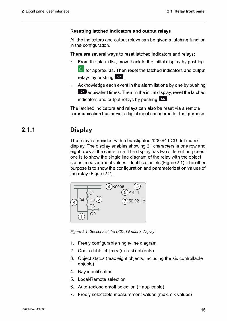
2.1.1 DisplayThe relay is provided with a backlighted 128x64 LCD dot matrixdisplay. The display enables showing 21 characters is one row andeight rows at the same time. The display has two different purposes:one is to show the single line diagram of the relay with the objectstatus, measurement values, identification etc (Figure2.1). The otherpurpose is to show the configuration and parameterization values ofthe relay (Figure 2.2).
23
4 5
1
6
K0006 L
AR: 1
50.02 Hz
Q1
Q0
Q3
Q9
Q4 7
Figure 2.1: Sections of the LCD dot matrix display
1. Freely configurable single-line diagram
2. Controllable objects (max six objects)
3. Object status (max eight objects, including the six controllableobjects)
4. Bay identification
5. Local/Remote selection
6. Auto-reclose on/off selection (if applicable)
7. Freely selectable measurement values (max. six values)
15V265M/en M/A005
2.1 Relay front panel2 Local panel user interface

2
3
4
5
1
6
PHASE CURRENTS
0A
0A
0A
0A
0A
0A
Mont
Evnt
Dr
IL1
IL2
IL3
I'L1
I'L2
I'L3
Meas
Imax
Figure 2.2: Sections of the LCD dot matrix display
1. Main menu column
2. The heading of the active menu
3. The cursor of the main menu
4. Possible navigating directions (push buttons)
5. Measured/setting parameter
6. Measured/set value
Backlight control
Display backlight can be switched on with a digital input, virtual inputor virtual output. LOCALPANELCONF/Display backlight ctrl settingis used for selecting trigger input for backlight control. When theselected input activates (rising edge), display backlight is set on for60 minutes.
2.1.2 Adjusting display contrastThe readability of the LCD varies with the brightness and thetemperature of the environment. The contrast of the display can beadjusted via the PC user interface, see Chapter 3 VAMPSET PCsoftware.
V265M/en M/A00516
2 Local panel user interface2.1 Relay front panel

2.2 Local panel operationsThe front panel can be used to control objects, change the local/remote status, read the measured values, set parameters, and toconfigure relay functions. Some parameters, however, can only beset by means of a PC connected to the local communication port.Some parameters are factory-set.
Moving in the menus
Main menu Submenus
protection enabling
I pick-up setting
Prot
OK
OK OK
moving in the menus_relay
Figure 2.3: Moving in the menus using local HMI
• To move in the main menu, push or .
• To move in submenus, push or .
• To enter a submenu, push and use or for movingdown or up in the menu.
•To edit a parameter value, push and .
•To go back to the previous menu, push .
•To go back to the first menu item in the main menu, push forat least three seconds.
NOTE: To enter the parameter edit mode, give the password. When thevalue is in edit mode, its background is dark.
17V265M/en M/A005
2.2 Local panel operations2 Local panel user interface

Main menu
The menu is dependent on the user’s configuration and the optionsaccording the order code. For example only the enabled protectionstages will appear in the menu.
A list of the local main menu
NoteANSI codeDescriptionNumber of menusMain menu
1Interactive mimic display1
1Double size measurements defined by the user5
Title screen with device name, time and firmwareversion.
1
Phase and winding current measurements, currentdifferential and angles, winding angles, Io, f, Phasesequence, symmetric currents and harmonics
13Meas
Time stamped min & max of currents9Imax
Maximum values of the last 31 days and the lasttwelve months
21Month
Events2Evnt
2Disturbance recorder2DR
Running hour counter. Active time of a selecteddigital input and time stamps of the latest start andstop.
2Runh
Day and week timers6TIMR
Digital inputs including virtual inputs5DI
Digital outputs (relays) and output matrix4DO
3External analogue inputs3ExtAI
3Externa analogue outputs3ExtAO
3External digital inputs3ExDI
3External digital outputs3ExDO
Protection counters, combined overcurrent status,protection status, protection enabling, cold loadand inrush detectionIf2> and block matrix
27Prot
Motor status1Mstat
466quent start protection4N>
1st differential stages7ΔI>
2nd differential stage5ΔI>>
450/511st overcurrent stage (primary side)5I>
450/512nd overcurrent stage (primary side)3I>>
450/511st overcurrent stage (secondary side)5I’>
450/512nd overcurrent stage (secondary side)3I’>>
448Stall protection stage3Ist>
446Current unbalance stage (primary side)3I2>
446Phase reversal / incorrect phase sequence stage3I2>>
446Current unbalance stage (secondary side)3I’2>
437Undercurrent stage3I<
V265M/en M/A00518
2 Local panel user interface2.2 Local panel operations

NoteANSI codeDescriptionNumber of menusMain menu
449Thermal overload stage3T>
450N/51N1st earth fault stage5Io>
450N/51N2nd earth fault stage3Io>>
450N/51N3rd earth fault stage3Io>>>
450N/51N4th earth fault stage3Io>>>>
41st programmable stage3Prg1
42nd programmable stage3Prg2
43rd programmable stage3Prg3
44th programmable stage3Prg4
45th programmable stage3Prg5
46th programmable stage3Prg6
47th programmable stage3Prg7
48th programmable stage3Prg8
468F2Second harmonic O/C stage3If2>
468F5Fifth harmonic O/C stage3If5>
450BFCircuit breaker failure protection3CBFP
4Circuit breaker wearing supervision4CBWE
4CT supervisor1CTSV
4CT’ supervisor1CT’SV
450ARCOptional arc protection stage for phase-to-phasefaults and delayed light signal.
4ArcI>
450NARCOptional arc protection stage for earth faults. Cur-rent input = I01
3ArcIo1>
450NARCOptional arc protection stage for earth faults. Cur-rent input = I02
3ArcIo2>
5Object definitions11OBJ
1Status and counters of user's logic2Lgic
6Device setup, scaling etc.10+2CONF
7Serial port and protocol configuration13Bus
Device selfdiagnosis6Diag
Notes
1. Configuration is done with VAMPSET
2. Recording files are read with VAMPSET
3. The menu is visible only if protocol "ExternalIO" is selected for one of the serial ports. Serial ports are configured inmenu "Bus".
4. The menu is visible only if the stage is enabled.
5. Objects are circuit breakers, disconnectors etc. Their position or status can be displayed and controlled in the inter-active mimic display.
6. There are two extra menus, which are visible only if the access level "operator" or "configurator" has been openedwith the corresponding password.
7. Detailed protocol configuration is done with VAMPSET.
19V265M/en M/A005
2.2 Local panel operations2 Local panel user interface

2.2.1 Menu structure of protection functionsThe general structure of all protection function menus is similaralthough the details do differ from stage to stage. As an example thedetails of the second overcurrent stage I>>menus are shown below.
First menu of I>> 50/51 stage
I>> STATUS 50 / 51
StatusSCntrTCntrSetGrpSGrpDIForce
-521-
OFF
ExDOProtI>
Iv>I >
I>>
Figure 2.4: First menu of I>> 50/51 stage
This is the status, start and trip counter and setting group menu. Thecontent is:
• Status –The stage is not detecting any fault at the moment. The stagecan also be forced to pick-up or trip is the operating level is“Configurator” and the force flag below is on. Operating levelsare explained in Chapter 2.2.4 Operating levels.
• SCntr 5The stage has picked-up a fault five times since the last reset orrestart. This value can be cleared if the operating level is at least“Operator”.
• TCntr 1The stage has tripped two times since the last reset or restart.This value can be cleared if the operating level is at least“Operator”.
• SetGrp 1The active setting group is one. This value can be edited if theoperating level is at least “Operator”. Setting groups are explainedin Chapter 2.2.2 Setting groups
• SGrpDI –The setting group is not controlled by any digital input. This valuecan be edited if the operating level is at least “Configurator”.
• Force OffThe status forcing and output relay forcing is disabled. This forceflag status can be set to “On” or back to “Off” if the operatinglevel is at least “Configurator”. If no front panel button is pressedwithin five minutes and there is no VAMPSET communication,the force flag will be set to “Off” position. The forcing is explainedin Chapter 2.3.4 Forced control (Force).
V265M/en M/A00520
2 Local panel user interface2.2 Local panel operations

Second menu of I>> 50/51 stage
I>> SET 50 / 51Stage setting group 1
ILmaxStatusI>>I>>t>>
403A-
1013A2.50xIn0.60s
ExDIExDOProt
CBWEOBJ
I>>
Figure 2.5: Second menu(next on the right) of I>> 50/51 stage
This is the main setting menu. The content is:
• Stage setting group 1These are the group 1 setting values. The other setting groupcan be seen by pressing push buttons and then or .Setting groups are explained in Chapter 2.2.2 Setting groups.
• ILmax 403AThe maximum of three measured phase currents is at themoment 403 A. This is the value the stage is supervising.
• Status –Status of the stage. This is just a copy of the status value in thefirst menu.
• I>> 1013 AThe pick-up limit is 1013 A in primary value.
• I>> 2.50 x INThe pick-up limit is 2.50 times the rated current of the generator.This value can be edited if the operating level is at least“Operator”. Operating levels are explained in Chapter 2.2.4Operating levels.
• t>> 0.60sThe total operation delay is set to 600 ms. This value can beedited if the operating level is at least “Operator”.
21V265M/en M/A005
2.2 Local panel operations2 Local panel user interface

Third menu of I>> 50/51 stage
I>> LOG 50/51
2006-09-1412:25:10.288TypeFltLoadEDly
1-22.86xIn0.99xIn81%
ExDIExDOProt
CBWEOBJ
I>>
FAULT LOG 1
SetGrp 1
Figure 2.6: Third and last menu (next on the right) of I>> 50/51 stage
This is the menu for registered values by the I>> stage. Fault logsare explained in Chapter 2.2.3 Fault logs.
• FAULT LOG 1This is the latest of the eight available logs. You may movebetween the logs by pressing push buttons and thenor .
• 2006-09-14Date of the log.
• 12:25:10.288Time of the log.
• Type 1-2The overcurrent fault has been detected in phases L1 and L2 (A& B, red & yellow, R/S, u&v).
• Flt 2.86 x INThe fault current has been 2.86 per unit.
• Load 0.99 x INThe average load current before the fault has been 0.99 pu.
• EDly 81%The elapsed operation delay has been 81% of the setting 0.60s = 0.49 s. Any registered elapsed delay less than 100 %meansthat the stage has not tripped, because the fault duration hasbeen shorter that the delay setting.
• SetGrp 1The setting group has been 1. This line can be reached bypressing and several times .
V265M/en M/A00522
2 Local panel user interface2.2 Local panel operations

2.2.2 Setting groupsMost of the protection functions of the relay have two setting groups.These groups are useful for example when the network topology ischanged frequently. The active group can be changed by a digitalinput, through remote communication or locally by using the localpanel.
The active setting group of each protection function can be selectedseparately. Figure 2.7 shows an example where the changing of theI> setting group is handled with digital input one (SGrpDI). If thedigital input is TRUE, the active setting group is group two andcorrespondingly, the active group is group one, if the digital input isFALSE. If no digital input is selected (SGrpDI = -), the active groupcan be selected by changing the value of the parameter SetGrp.
Figure 2.7: Example of protection submenu with setting group parameters
The changing of the setting parameters can be done easily. Whenthe desired submenu has been found (with the arrow keys), press
to select the submenu. Now the selected setting group isindicated in the down-left corner of the display (See Figure2.8). Set1is setting group one and Set2 is setting group two. When the neededchanges, to the selected setting group, have been done, pressor to select another group ( is used when the active settinggroup is 2 and is used when the active setting group is 1).
Figure 2.8: Example of I> setting submenu
23V265M/en M/A005
2.2 Local panel operations2 Local panel user interface

2.2.3 Fault logsAll the protection functions include fault logs. The fault log of afunction can register up to eight different faults with time stampinformation, fault values etc. The fault logs are stored in non-volatilememory. Each function has its own logs. The fault logs are notcleared when power is switched off. The user is able to clear all logsusing VAMPSET. Each function has its own logs (Figure 2.9).
Figure 2.9: Example of fault log
To see the values of, for example, log two, press then to selectthe current log (log one). The current log number is then indicatedin the down-left corner of the display (SeeFigure 2.10, Log2 = logtwo). The log two is selected by pressing once.
Figure 2.10: Example of selected fault log
V265M/en M/A00524
2 Local panel user interface2.2 Local panel operations
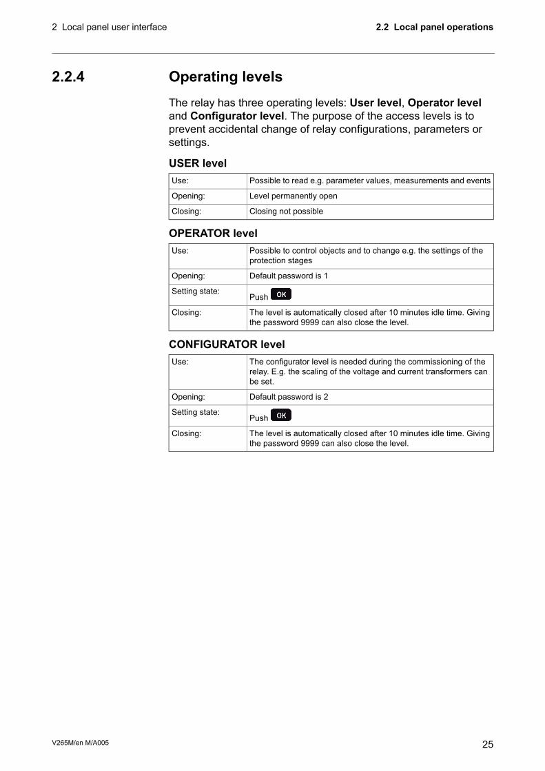
2.2.4 Operating levelsThe relay has three operating levels: User level, Operator leveland Configurator level. The purpose of the access levels is toprevent accidental change of relay configurations, parameters orsettings.
USER levelPossible to read e.g. parameter values, measurements and eventsUse:
Level permanently openOpening:
Closing not possibleClosing:
OPERATOR levelPossible to control objects and to change e.g. the settings of theprotection stages
Use:
Default password is 1Opening:
PushSetting state:
The level is automatically closed after 10 minutes idle time. Givingthe password 9999 can also close the level.
Closing:
CONFIGURATOR levelThe configurator level is needed during the commissioning of therelay. E.g. the scaling of the voltage and current transformers canbe set.
Use:
Default password is 2Opening:
PushSetting state:
The level is automatically closed after 10 minutes idle time. Givingthe password 9999 can also close the level.
Closing:
25V265M/en M/A005
2.2 Local panel operations2 Local panel user interface

Opening access1.
Push and on the front panel
ENTER PASSWORD
0***
Figure 2.11: Opening the access level
2. Enter the password needed for the desired level: the passwordcan contain four digits. The digits are supplied one by one byfirst moving to the position of the digit using and then settingthe desired digit value using .
3. Push .
Password handling
It is possible to restore the password(s) in case the password is lostor forgotten. In order to restore the password(s), a relay program isneeded. The virtual serial port settings are 38400 bps, 8 data bits,no parity and one stop bit. The bit rate is configurable via the frontpanel.
DescriptionCommand
Get the break code (Example: 6569403)get pwd_break
Get the serial number of the relay (Example: 12345)get serno
Send both the numbers to your nearest Schneider Electric CustomerCare Centre and ask for a password break. A device specific breakcode is sent back to you. That code will be valid for the next twoweeks.
DescriptionCommand
Restore the factory default passwords (“4435876” is just anexample. The actual code should be asked from from yournearest Schneider Electric Customer Care Centre.)
set pwd_break=4435876
Now the passwords are restored to the default values (SeeChapter 2.2.4 Operating levels ).
V265M/en M/A00526
2 Local panel user interface2.2 Local panel operations

2.3 Operating measures
2.3.1 Control functionsThe default display of the local panel is a single-line diagram includingrelay identification, Local/Remote indication, Auto-reclose on/offselection and selected analogue measurement values.
Please note that the operator password must be active in order tobe able to control the objects. Please refer to Chapter2.2.4 Operatinglevels.
Toggling Local/Remote control1. Push . The previously activated object starts to blink.
2. Select the Local/Remote object (“L” or “R” squared) by usingarrow keys.
3. Push . The L/R dialog opens. Select “REMOTE” to enableremote control and disable local control. Select “LOCAL” toenable local control and disable remote control.
4. Confirm the setting by pushing . The Local/Remote state willchange.
Object control1. Push . The previously activated object starts to blink.
2. Select the object to control by using arrow keys. Please note thatonly controllable objects can be selected.
3. Push . A control dialog opens.
4. Select the “Open” or “Close” command by using the or .
5. Confirm the operation by pushing . The state of the objectchanges.
Toggling virtual inputs1. Push . The previously activated object starts to blink.
2. Select the virtual input object (empty or black square)
3. The dialog opens
4. Select “VIon” to activate the virtual input or select “VIoff” todeactivate the virtual input
27V265M/en M/A005
2.3 Operating measures2 Local panel user interface

2.3.2 Measured dataThe measured values can be read from the main menus and theirsubmenus. Furthermore, any measurement value in the followingtable can be displayed on the main view next to the single linediagram. Up to six measurements can be shown.
DescriptionMenu/SubmenuValue
Phase current IL1 [A]Meas/PHASE CURRENTSIL1
Phase current IL2 [A]Meas/PHASE CURRENTSIL2
Phase current IL3 [A]Meas/PHASE CURRENTSIL3
Phase current I’L1 [A]Meas/PHASE CURRENTSI’L1
Phase current I’L2 [A]Meas/PHASE CURRENTSI’L2
Phase current I’L3 [A]Meas/PHASE CURRENTSI’L3
Winding current IL1 [xImot]Meas/WINDING CURRENTSIL1w
Winding current IL2 [xImot]Meas/WINDING CURRENTSIL2w
Winding current IL3 [xImot]Meas/WINDING CURRENTSIL3w
Winding current I’L1 [xImot]Meas/WINDING CURRENTSI’L1w
Winding current I’L2 [xImot]Meas/WINDING CURRENTSI’L2w
Winding current IL’3 [xImot]Meas/WINDING CURRENTSI’L3w
Differential current IL1 [xImot]Meas/CURRENT DIFFdIL1
Differential current IL2 [xImot]Meas/CURRENT DIFFdIL2
Differential current IL3 [xImot]Meas/CURRENT DIFFdIL3
Differential angle IL1 / I’l1 [deg]Meas/CURRENT DIFFΔIL1φ
Differential angle IL2 / I’l2 [deg]Meas/CURRENT DIFFΔIL2φ
Differential angle IL3 /I’l3 [deg]Meas/CURRENT DIFFΔIL3φ
Measured phase angle L1 [deg]Meas/ANGLESIL1
Measured phase angle L2 [deg]Meas/ANGLESIL2
Measured phase angle L3 [deg]Meas/ANGLESIL3
Measured phase angle L’1 [deg]Meas/ANGLESI’L1
Measured phase angle L’2 [deg]Meas/ANGLESI’L2
Measured phase angle L’3 [deg]Meas/ANGLESI’L3
Measured winding angle L1 [deg]Meas/ WINDING ANGLESIL1
Measured winding angle L2 [deg]Meas/ WINDING ANGLESIL2
Measured winding angle L3 [deg]Meas/ WINDING ANGLESIL3
Measured winding angle L’1 [deg]Meas/ WINDING ANGLESI’L1
Measured winding angle L’2 [deg]Meas/WINDING ANGLESI’L2
Measured winding angle L’3 [deg]Meas/WINDING ANGLESI’L3
Primary value of zerosequence/ residual current Io [A]Meas/Io,f,PHASE SEQ.Io
Primary value of zero-sequence/residual current Io2 [A]Meas/Io,f,PHASE SEQ.Io2
Frequency [Hz]Meas/Io,f,PHASE SEQ.f
Adopted Frequency [Hz]Meas/Io,f,PHASE SEQfAdop
Meas/Io,f,PHASE SEQIseq
Meas/Io,f,PHASE SEQI’seq
V265M/en M/A00528
2 Local panel user interface2.3 Operating measures

DescriptionMenu/SubmenuValue
Calculated Io [A]Meas/SYMMETRIC CURRENTS.IoCalc
Positive sequence current [A]Meas/SYMMETRIC CURRENTSI1
Negative sequence current [A]Meas/SYMMETRIC CURRENTSI2
Calculated I’o [A]Meas/SYMMETRIC CURRENTS.I’oCalc
Positive sequence current [A]Meas/SYMMETRIC CURRENTSI’1
Negative sequence current [A]Meas/SYMMETRIC CURRENTSI’2
Total harmonic distortion of the mean value of phase currents [%]Meas/HARM. DISTORTIONTHDIL
Total harmonic distortion of phase current IL1 [%]Meas/HARM. DISTORTIONTHDIL1
Total harmonic distortion of phase current IL2 [%]Meas/HARM. DISTORTIONTHDIL2
Total harmonic distortion of phase current IL3 [%]Meas/HARM. DISTORTIONTHDIL3
Total harmonic distortion of the mean value of phase currents [%]Meas/HARM. DISTORTIONTHDI’L
Total harmonic distortion of phase current I’L1 [%]Meas/HARM. DISTORTIONTHDI’L1
Total harmonic distortion of phase current I’L2 [%]I/HARM. DISTORTIONTHDI’L2
Total harmonic distortion of phase current I’L3 [%]I/HARM. DISTORTIONTHDI’L3
Harmonics of phase current IL1 [%] (see Figure 2.12)I/HARMONICS of IL1Diagram
Harmonics of phase current IL2 [%] (see Figure 2.12)I/HARMONICS of IL2Diagram
Harmonics of phase current IL3 [%] (see Figure 2.12)I/HARMONICS of IL3Diagram
Harmonics of phase current I’L1 [%] (see Figure 2.12)I/HARMONICS of I’L1Diagram
Harmonics of phase current I’L2 [%] (see Figure 2.12)I/HARMONICS of I’L2Diagram
Harmonics of phase current I’L3 [%] (see Figure 2.12)I/HARMONICS of I’L3Diagram
Figure 2.12: Example of harmonics bar display
29V265M/en M/A005
2.3 Operating measures2 Local panel user interface

2.3.3 Reading event registerThe event register can be read from the Evnt submenu:
1. Push once.
2. The EVENT LIST appears. The display contains a list of all theevents that have been configured to be included in the eventregister.
Figure 2.13: Example of an event register
3. Scroll through the event list with the and .
4. Exit the event list by pushing .
It is possible to set the order in which the events are sorted. If the“Order” -parameter is set to “New-Old”, then the first event in theEVENT LIST is the most recent event.
V265M/en M/A00530
2 Local panel user interface2.3 Operating measures

2.3.4 Forced control (Force)In some menus it is possible to switch a function on and off by usinga force function. This feature can be used, for instance, for testinga certain function. The force function can be activated as follows:
1. Open Access level CONFIGURATION.
2. Move to the setting state of the desired function, for example DO(see Chapter 2.4 Configuration and parameter setting).
3. Select the Force function (the background color of the force textis black).
force
DO
Pick RELAY OUTPUTS 1Enable forcing
T1T2A1A2
Force
0000
OFF
Figure 2.14: Selecting Force function
4. Push .
5. Push the or to change the "OFF" text to "ON", that is,to activate the Force function.
6. Push to return to the selection list. Choose the signal to becontrolled by force with the and , for instance the T1signal.
7. Push to confirm the selection. Signal T1 can now becontrolled by force.
8. Push the or to change the selection from "0" (not alert)to "1" (alert) or vice versa.
9. Push to execute the forced control operation of the selectedfunction, e.g., making the output relay of T1 to pick up.
10. Repeat the steps 7 and 8 to alternate between the on and offstate of the function.
11. Repeat the steps 1 – 4 to exit the Force function.
12.Push to return to the main menu.
NOTE: All the interlockings and blockings are bypassed when the forcecontrol is used.
31V265M/en M/A005
2.3 Operating measures2 Local panel user interface

2.4 Configuration and parameter settingThe minimum procedure to configure a device is
1. Open the access level "Configurator". The default password forconfigurator access level is 2.
2. Set the rated values in menu [CONF] including at least currenttransformers and a protected transformer rating. Also the dateand time settings are in this same main menu.
3. Enable the needed protection functions and disable the rest ofthe protection functions in main menu [Prot].
4. Set the setting parameter of the enable protection stagesaccording the application.
5. Connect the output relays to the start and trip signals of theenabled protection stages using the output matrix. This can bedone in main menu [DO], although the VAMPSET program isrecommended for output matrix editing.
6. Configure the needed digital inputs in main menu [DI].
7. Configure blocking and interlockings for protection stages usingthe block matrix. This can be done in main menu [Prot], althoughVAMPSET is recommended for block matrix editing.
Some of the parameters can only be changed via the RS-232 serialport using the VAMPSET software. Such parameters, (for examplepasswords, blockings and mimic configuration) are normally set onlyduring commissioning.
Some of the parameters require the restarting of the relay. Thisrestarting is done automatically when necessary. If a parameterchange requiresrestarting, the display will show as Figure 2.15
Figure 2.15: Example of auto-reset display
Press to return to the setting view. If a parameter must bechanged, press again. The parameter can now be set. Whenthe parameter change is confirmed with , a [RESTART]- textappears to the top-right corner of the display. This means thatauto-resetting is pending. If no key is pressed, the auto-reset will beexecuted within few seconds.
V265M/en M/A00532
2 Local panel user interface2.4 Configuration and parameter setting
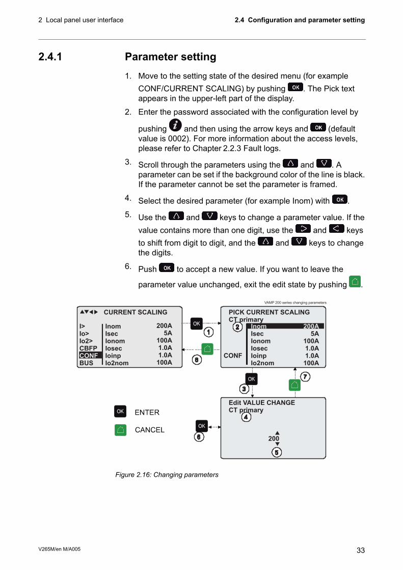
2.4.1 Parameter setting1. Move to the setting state of the desired menu (for example
CONF/CURRENT SCALING) by pushing . The Pick textappears in the upper-left part of the display.
2. Enter the password associated with the configuration level by
pushing and then using the arrow keys and (defaultvalue is 0002). For more information about the access levels,please refer to Chapter 2.2.3 Fault logs.
3. Scroll through the parameters using the and . Aparameter can be set if the background color of the line is black.If the parameter cannot be set the parameter is framed.
4. Select the desired parameter (for example Inom) with .
5. Use the and keys to change a parameter value. If thevalue contains more than one digit, use the and keysto shift from digit to digit, and the and keys to changethe digits.
6. Push to accept a new value. If you want to leave the
parameter value unchanged, exit the edit state by pushing .
VAMP 200 series changing parameters
Figure 2.16: Changing parameters
33V265M/en M/A005
2.4 Configuration and parameter setting2 Local panel user interface

2.4.2 Setting range limitsIf the given parameter setting values are out-of-range values, a faultmessage will be shown when the setting is confirmed with .Adjust the setting to be within the allowed range.
Figure 2.17: Example of a fault message
The allowed setting range is shown in the display in the setting mode.
To view the range, push . Push to return to the setting mode.
Figure 2.18: Allowed setting ranges show in the display
2.4.3 Disturbance recorder menu DRVia the submenus of the disturbance recorder menu the followingfunctions and features can be read and set:
Distrubance settings
1. Manual trigger (ManTrg)
2. Status (Status)
3. Clear oldest record (Clear)
4. Clear all records (ClrAll)
5. Recording completion (Stored)
6. Count of ready records (ReadyRec)
V265M/en M/A00534
2 Local panel user interface2.4 Configuration and parameter setting

Recorder settings
1. Manual trigger (MnlTrig)
2. Sample rate (SR)
3. Recording time (Time)
4. Pre trig time (PreTrig)
5. Mximum time (MaxLen)
6. Count of ready records (ReadyRec)
Rec. channels
• Add a link to the recorder (AddCh)
• Clear all links (ClrCh)
Available links
• DO, DI
• f
• IoCalc, I’oCalc
• I1, I2, I’1, I’2
• I2/I1, I2/Imot, I’2/I1, I’2/Imot
• IL, I’L
• IL3, IL2, IL1, I’L3, I’L2, I’L1
• IL1RMS, IL2RMS, IL3RMS
• ILmin, ILmax, I’Lmin, I’Lmax
• T
• Io2, Io1
• THD1, THD2, THD3
• ΔIL1, ΔIL2, ΔIL3
• IL1w, IL2w, IL3w, I’L1w, I’L2w, I’L3w
2.4.4 Configuring digital inputs DIThe following functions can be read and set via the submenus of thedigital inputs menu:
1. The status of digital inputs (DIGITAL INPUTS 1-6)
2. Operation counters (DI COUNTERS)
3. Operation delay (DELAYs for DigIn)
4. The polarity of the input signal (INPUT POLARITY). Eithernormally open (NO) or normally closed (NC) circuit.
5. Event enabling EVENT MASK1
35V265M/en M/A005
2.4 Configuration and parameter setting2 Local panel user interface
2.4.5 Configuring digital outputs DOThe following functions can be read and set via the submenus of thedigital outputs menu:
• The status of the output relays (RELAY OUTPUTS1 and 2)
• The forcing of the output relays (RELAYOUTPUTS1 and 2) (onlyif Force = ON):
- Forced control (0 or 1) of the Trip relays
- Forced control (0 or 1) of the Alarm relays
- Forced control (0 or 1) of the SF relay
• The configuration of the output signals to the output relays. Theconfiguration of the operation indicators (LED) Alarm and Tripand application specific alarm leds A, B and C (that is, the outputrelay matrix).
NOTE: The amount of Trip and Alarm relays depends on the relay type andoptional hardware.
2.4.6 Protection menu ProtThe following functions can be read and set via the submenus of theProt menu:
1. Reset all the counters (PROTECTION SET/ClAll)
2. Read the status of all the protection functions (PROTECTSTATUS 1 – x)
3. Enable and disable protection functions (ENABLED STAGES 1– x)
4. Define the interlockings using block matrix (only with VAMPSET)
Each stage of the protection functions can be disabled or enabledindividually in the Prot menu. When a stage is enabled, it will be inoperation immediately without a need to reset the relay.
The relay includes several protection functions. However, theprocessor capacity limits the number of protection functions that canbe active at the same time.
2.4.7 Configuration menu CONFThe following functions and features can be read and set via thesubmenus of the configuration menu:
V265M/en M/A00536
2 Local panel user interface2.4 Configuration and parameter setting

Device setup
• Bit rate for the command line interface in ports X4 and the frontpanel. The front panel is always using this setting. If SPABUS isselected for the rear panel local port X4, the bit rate is accordingSPABUS settings.
• Access level [Acc]
• PC access level [PCAcc]
Language
• List of available languages in the relay
Current scaling
• Rated phase CT primary current (Inom)
• Rated phase CT secondary current (Isec)
• Rated input of the relay [Iinput]. 5 A or 1 A. This is specified inthe order code of the device.
• Rated phase CT’ primary current (I’nom)
• Rated phase CT’ secondary current (I’sec)
• Rated input of the relay [I’input]. 5 A or 1 A. This is specified inthe order code of the device.
• Rated value of I0 CT primary current (Ionom)
• Rated value of I0 CT secondary current (Iosec)
• Rated I01 input of the relay [Ioinp]. 5 A or 1 A. This is specifiedin the order code of the device.
• Rated value of I02 CT primary current (Io2nom)
• Rated value of I02 CT secondary current (Io2sec)
• Rated I02 input of the relay [Io2inp]. 5A, 1 A or 0.2 A. This isspecified in the order code of the device.
The rated input values are usually equal to the rated secondary valueof the CT.
The rated CT secondary may be greater than the rated input but thecontinuous current must be less than four times the rated input. Incompensated, high impedance earthed and isolated networks usingcable transformer to measure residual current I0, it is quite usual touse a relay with 1 A or 0.2 A input although the CT is 5 A or 1A. Thisincreases the measurement accuracy.
The rated CT secondary may also be less than the rated input butthe measurement accuracy near zero current will decrease.
37V265M/en M/A005
2.4 Configuration and parameter setting2 Local panel user interface

Motor setting
• Motor nominal current
Frequency adaptation
The relay can automatically detect the correct network frequency.User can also fix the frequency if the mode is set to manual and thefrequency value is set.
• Automatic or manual mode of frequency adaptation (MODE)
• Adopted frequency (fAdop)
Device info
• Relay type (Type VAMP 265M)
• Serial number (SerN)
• Software version (PrgVer)
• Bootcode version (BootVer)
Date/time setup
• Day, month and year (Date)
• Time of day (Time)
• Date format (Style). The choices are "yyyy-mm-dd", "dd.nn.yyyy"and "mm/dd/yyyy".
Clock synchronisation
• Digital input for minute sync pulse (SyncDI). If any digital inputis not used for synchronization, select "-".
• UTC time zone for SNTP synchronization (TZone)
NOTE: This is a decimal number. For example for state of Nepal thetime zone 5:45 is given as 5.75
• Daylight saving time for NTP synchronization (DST).
• Detected source of synchronization (SyScr).
• Synchronization message counter (MsgCnt).
• Latest synchronization deviation (Dev).
The following parameters are visible only when the access level ishigher than "User".
• Offset, i.e. constant error, of the synchronization source (SyOS).
• Auto adjust interval (AAIntv).
• Average drift direction (AvDrft): "Lead" or "lag".
• Average synchronization deviation (FilDev).
V265M/en M/A00538
2 Local panel user interface2.4 Configuration and parameter setting

SW options
• Application mode, fixed Motor (ApplMod)
• External led module installed (Ledmodule)
• Mimic display selection (MIMIC)
2.4.8 Protocol menu BusThere are three communication ports in the rear panel. In additionthere is a connector in the front panel overruling the local port in therear panel.
Remote port
• Communication protocol for remote port X5 [Protocol].
• Message counter [Msg#]. This can be used to verify that thedevice is receiving messages.
• Communication error counter [Errors].
• Communication time-out error counter [Tout].
• Information of bit rate/data bits/parity/stop bits. This value is notdirectly editable. Editing is done in the appropriate protocol settingmenus.
The counters are useful when testing the communication.
Local port X4 (pins 2, 3 and 5)
This port is disabled, if a cable is connected to the front panelconnector.
• Communication protocol for the local port X4 [Protocol]. ForVAMPSET use "None" or "SPABUS".
• Message counter [Msg#]. This can be used to verify that thedevice is receiving messages.
• Communication error counter [Errors].
• Communication time-out error counter [Tout].
• Information of bit rate/data bits/parity/stop bits. This value is notdirectly editable. Editing is done in the appropriate protocol settingmenus. For VAMPSET and protocol "None" the setting is donein menu CONF/DEVICE SETUP.
The counters are useful when testing the communication.
39V265M/en M/A005
2.4 Configuration and parameter setting2 Local panel user interface

PC (Local/SPA-bus)
This is a second menu for local port X4. The VAMPSETcommunication status is showed.
• Bytes/size of the transmitter buffer [Tx].
• Message counter [Msg#]. This can be used to verify that thedevice is receiving messages.
• Communication error counter [Errors]
• Communication time-out error counter [Tout].
• Same information as in the previous menu.
Extension port (pins 7, 8 and 5)
• Communication protocol for extension port X4 [Protocol].
• Message counter [Msg#]. This can be used to verify that thedevice is receiving messages.
• Communication error counter [Errors].
• Communication time-out error counter [Tout].
• Information of bit rate/data bits/parity/stop bits. This value is notdirectly editable. Editing is done in the appropriate protocol settingmenus.
Ethernet port
These parameters are used by the ethernet interface module. Forchanging the nnn.nnn.nnn.nnn style parameter values, VAMPSETis recommended.
• Ethernet port protocol [Protoc].
• IP Port for protocol [Port]
• IP address [IpAddr].
• Net mask [NetMsk].
• Gateway [Gatew].
• Name server [NameSw].
• Network time protocol (NTP) server [NTPSvr].
• TCP Keep alive interval [KeepAlive]
• MAC address [MAC]
• IP Port for VAMPSET [VS Port]
• Message counter [Msg#]
• Error counter [Errors]
• Timeout counter [Tout]
V265M/en M/A00540
2 Local panel user interface2.4 Configuration and parameter setting
Modbus
• Modbus address for this slave device [Addr]. This address hasto be unique within the system.
• Modbus bit rate [bit/s]. Default is "9600".
• Parity [Parity]. Default is "Even".
For details, see Chapter 9.2.2 Modbus TCP and Modbus RTU.
External I/O protocol
This is a Modbus master protocol to communicate with the extensionI/O modules connected to the extension port. Only one instance ofthis protocol is possible.
• Bit rate [bit/s]. Default is "9600".
• Parity [Parity]. Default is "Even".
For details, see Chapter 9.2.8 External I/O (Modbus RTU master).
SPA-bus
Several instances of this protocol are possible.
• SPA-bus address for this device [Addr]. This address has to beunique within the system.
• Bit rate [bit/s]. Default is "9600".
• Event numbering style [Emode]. Default is "Channel".
For details, see Chapter 9.2.4 SPA-bus.
IEC 60870-5-103
Only one instance of this protocol is possible.
• Address for this device [Addr]. This address has to be uniquewithin the system.
• Bit rate [bit/s]. Default is "9600".
• Minimum measurement response interval [MeasInt].
• ASDU6 response time mode [SyncRe].
• Debug mode [SyncDebug].
For details, see Chapter 9.2.5 IEC 60870-5-103.
IEC 103 Disturbance recordings
For details, see Table 9.11.
41V265M/en M/A005
2.4 Configuration and parameter setting2 Local panel user interface

Profibus
Only one instance of this protocol is possible.
• [Mode]
• Bit rate [bit/s]. Use 2400 bps. This parameter is the bit ratebetween the main CPU and the Profibus ASIC. The actualProfibus bit rate is automatically set by the Profibus master andcan be up to 12 Mbit/s.
• Event numbering style [Emode].
• Size of the Profibus Tx buffer [InBuf].
• Size of the Profibus Rx buffer [OutBuf].When configuring the Profibus master system, the length of thesebuffers are needed. The size of the both buffers is set indirectlywhen configuring the data items for Profibus.
• Address for this slave device [Addr]. This address has to beunique within the system.
• Profibus converter type [Conv]. If the shown type is a dash “-“,either Profibus protocol has not been selected or the device hasnot restarted after protocol change or there is a communicationproblem between the main CPU and the Profibus ASIC.
For details, see Chapter 9.2.3 Profibus DP.
DNP3
Only one instance of this protocol is possible.
• Bit rate [bit/s]. Default is "9600".
• [Parity].
• Address for this device [SlvAddr]. This address has to be uniquewithin the system.
• Master's address [MstrAddr].
For details, see Chapter 9.2.6 DNP 3.0.
IEC 60870-5-101
• Bit rate [bit/s]. Default is “9600”.
• [Parity].
• Link layer address for this device [LLAddr].
• ASDU address [ALAddr].
For details, see Chapter 9.2.7 IEC 60870-5-101.
V265M/en M/A00542
2 Local panel user interface2.4 Configuration and parameter setting

DeviceNet
• Bit rate [bit/s]. Default is “125kbps”.
• Slave address [SlvAddr]
For details, see Chapter 9.2.12 DeviceNet.
2.4.9 Single line diagram editingThe single-line diagram is drawn with the VAMPSET software. Formore information, please refer to the VAMPSET manual(VVAMPSET/EN M/xxxx).
Bay 0 L
0A
0.000A
0kW
0Kva r
Figure 2.19: Single line diagram
2.4.10 Blocking and Interlocking configurationThe configuration of the blockings and interlockings is done with theVAMPSET software. Any start or trip signal can be used for blockingthe operation of any protection stage. Furthermore, the interlockingbetween objects can be configured in the same blocking matrix ofthe VAMPSET software. For more information, please refer to theVAMPSET manual (VVAMPSET/EN M/xxxx).
43V265M/en M/A005
2.4 Configuration and parameter setting2 Local panel user interface

3 VAMPSET PC software
The PC user interface can be used for:
• On-site parameterization of the relay
• Loading relay software from a computer
• Reading measured values, registered values and events to acomputer
• Continuous monitoring of all values and events
Two RS 232 serial ports are available for connecting a local PC withVAMPSET to the relay; one on the front panel and one on the rearpanel of the relay. These two serial ports are connected in parallel.However, if the connection cables are connected to both ports, onlythe port on the front panel will be active. To connect a PC to a serialport, use a connection cable of type VX 003-3.
The VAMPSET program can also use TCP/IP LAN connection.Optional hardware is required.
There is a free of charge PC program called VAMPSET availablefor configuration and setting of VAMP relays. Please download thelatest VAMPSET.exe from our web page. For more information aboutthe VAMPSET software, please refer to the user’s manual with thecode VVAMPSET/EN M/xxxx. Also the VAMPSET user’s manual isavailable at our web site.
3.1 Folder viewIn VAMPSET version 2.2.136, a feature called ”Folder view” wasintroduced.
The idea of folder view is to make it easier for the user to work withrelay functions inside VAMPSET. When folder view is enabled,VAMPSET gathers similar functions together and places themappropriately under seven different folders (GENERAL,MEASUREMENTS, INPUTS/OUTPUTS, MATRIX, LOGS andCOMMUNICATION). The contents (functions) of the folders dependon the relay type and currently selected application mode.
Folder view can be enabled in VAMPSET via ProgramSettings dialog(Settings -> Program Settings), see Figure 3.1.
V265M/en M/A00544
3 VAMPSET PC software

Figure 3.1: Enable folder view setting in Program Settings dialog
NOTE: It is possible to enable/ disable the folder view only when VAMPSETis disconnected from the relay and there is no configuration fileopened.
When folder view is enabled, folder buttons become visible inVAMPSET, see Figure3.2. Currently selected folder appears in bold.
Figure 3.2: Folder view buttons
45V265M/en M/A005
3.1 Folder view3 VAMPSET PC software

4 Introduction
The numerical VAMP differential protection include all the essentialprotection functions needed to protect asynchronous andsynchronous motors for industry, power plants and offshoreapplications including motor and generator differential protection.Further, the device includes several programmable functions, suchas arc (option), circuit breaker protection and communicationprotocols for various protection and communication situations.
The generator and motor differential protection relay VAMP 265Mcan be used for selective differential overcurrent, short-circuitprotection of generators and motors in solidly or impedance earthedpower systems. The relay can also be used for single, two orthree-phase overcurrent and/or sensitive earth fault protection.
4.1 Main features• Fully digital signal handling with a powerful 16-bit microprocessor,
and high measuring accuracy on all the setting ranges due to anaccurate 16-bit A/D conversion technique.
• Wide setting ranges for the protection functions, e.g. the earthfault protection can reach a sensitivity of 0.5%.
• The device can bematched to the requirements of the applicationby disabling the functions that are not needed.
• Flexible control and blocking possibilities due to digital signalcontrol inputs (DI) and outputs (DO).
• Easy adaptability of the device to various substations and alarmsystems due to flexible signal-grouping matrix in the device.
• Freely configurable display with six measurement values.
• Freely configurable interlocking schemes with basic logicfunctions.
• Recording of events and fault values into an event register fromwhich the data can be read via a keypad and a local HMI or bymeans of a PC based VAMPSET user interface.
• Latest events and indications are in non-volatile memory.
• Easy configuration, parameterisation and reading of informationvia local HMI, or with a VAMPSET user interface.
• Easy connection to power plant automation system due to aversatile serial connection and several available communicationprotocols.
V265M/en M/A00546
4 Introduction

• Built-in, self-regulating ac/dc converter for auxiliary power supplyfrom any source within the range from 40 to 265 Vdc or Vac. Thealternative power supply is for 18 to 36 Vdc.
• Built-in disturbance recorder for evaluating all the analogue anddigital signals.
• Eight (8) programmable stages for alarming or protectionpurposes
4.2 Principles of numerical protectiontechniquesThe device is using numerical technology. This means that all thesignal filtering, protection and control functions are implementedthrough digital processing.
The numerical technique used is primarily based on an adapted FastFourier Transformation (FFT) algorithm. Synchronized sampling ofthe measured voltage and current signals is used. The sample rateis 32 samples/cycle within the frequency range 45 Hz – 65 Hz. Thefrequency is measured from the current signals L1 and L2 and usedto synchronize the sampling rate. Therefore secondary testing of abrand new device should be started by injecting stabile systemfrequency current signal in nominal magnitude. The learned frequencyis used for sampling rate synchronization when the measured currentis less than 20% of nominal value. The local network frequency canalso be manually given for the relay.
Apart from the FFT calculations, some protection functions alsorequire the symmetrical components to be calculated for obtainingthe positive, negative and zero phase sequence components of themeasured quantity. For example, the function of the unbalanced loadprotection stage is based on the use of the negative phase sequencecomponent of the current.
Figure 4.1 shows a hardware block diagram of the relay. The maincomponents are the current and voltage inputs, digital input elements,output relays, A/D converters and the microcomputer and a powersupply unit.
Figure 4.2 shows the inputs and outputs of a general protectionfunction. The FFT block is calculating the fundamental frequencyphasors and also harmonics used by some protection functions. Theblock matrix is used for simple interlocking. (More complexinterlocking is done with the user's programmable logic). The outputmatrix is used to connect the pick-up and trip signals from protectionblocks to the output relays and indicators.
Figure 4.3 shows a block diagram of a basic overcurrent orovervoltage function with definite and inverse operation time.
47V265M/en M/A005
4.2 Principles of numerical protection techniques4 Introduction

A
D
Current inputs
Digital inputs
Auxiliary power
Antialiasingfilter
16 bitA/D coonverter
Display andkeyboard
µP&
menory
Trip
relays
Alarm
relays
SPA bus, Modbus
Profibus DP,
fibre connectors
VAMP265K211
Figure 4.1: Principle block diagram of the VAMP hardware
Figure 4.2: Block diagram of signal processing and protection software
Figure 4.3: Block diagram of a basic protection function
V265M/en M/A00548
4 Introduction4.2 Principles of numerical protection techniques

5 Protection functions
Each protection stage can independently be enabled or disabledaccording to the requirements of the intended application.
5.1 Maximum number of protection stagesin one applicationThe device limits the maximum number of enabled stages to about30, depending of the type of the stages.
For more information, please see the configuration instructions inChapter 2.4 Configuration and parameter setting.
5.2 General features of protection stagesSetting groups
Most stages have two setting groups. Changing between settinggroups can be controlled manually or using any of the digital inputs,virtual inputs, virtual outputs or LED indicator signals. By using virtualI/O the active setting group can be controlled using the local paneldisplay, any communication protocol or using the inbuiltprogrammable logic functions.
Forcing start or trip condition for testing
The status of a protection stage can be one of the followings:
• Ok = ‘-‘The stage is idle and is measuring the analog quantity for theprotection. No fault detected.
• BlockedThe stage is detecting a fault but blocked by some reason.
• StartThe stage is counting the operation delay.
• TripThe stage has tripped and the fault is still on.
The blocking reason may be an active signal via the block matrixfrom other stages, the programmable logic or any digital input. Somestages also have inbuilt blocking logic. For example an underfrequency stage is blocked if voltage is too low. For more detailsabout block matrix, see Chapter 8.5 Blocking matrix.
49V265M/en M/A005
5 Protection functions
Forcing start or trip condition for testing purposes
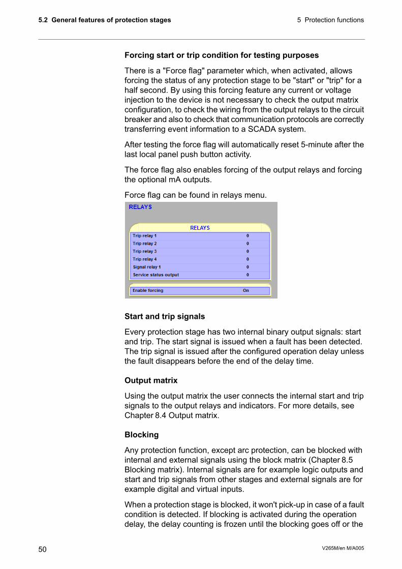
There is a "Force flag" parameter which, when activated, allowsforcing the status of any protection stage to be "start" or "trip" for ahalf second. By using this forcing feature any current or voltageinjection to the device is not necessary to check the output matrixconfiguration, to check the wiring from the output relays to the circuitbreaker and also to check that communication protocols are correctlytransferring event information to a SCADA system.
After testing the force flag will automatically reset 5-minute after thelast local panel push button activity.
The force flag also enables forcing of the output relays and forcingthe optional mA outputs.
Force flag can be found in relays menu.
Start and trip signals
Every protection stage has two internal binary output signals: startand trip. The start signal is issued when a fault has been detected.The trip signal is issued after the configured operation delay unlessthe fault disappears before the end of the delay time.
Output matrix
Using the output matrix the user connects the internal start and tripsignals to the output relays and indicators. For more details, seeChapter 8.4 Output matrix.
Blocking
Any protection function, except arc protection, can be blocked withinternal and external signals using the block matrix (Chapter 8.5Blocking matrix). Internal signals are for example logic outputs andstart and trip signals from other stages and external signals are forexample digital and virtual inputs.
When a protection stage is blocked, it won't pick-up in case of a faultcondition is detected. If blocking is activated during the operationdelay, the delay counting is frozen until the blocking goes off or the
V265M/en M/A00550
5 Protection functions5.2 General features of protection stages
pick-up reason, i.e. the fault condition, disappears. If the stage isalready tripping, the blocking has no effect.
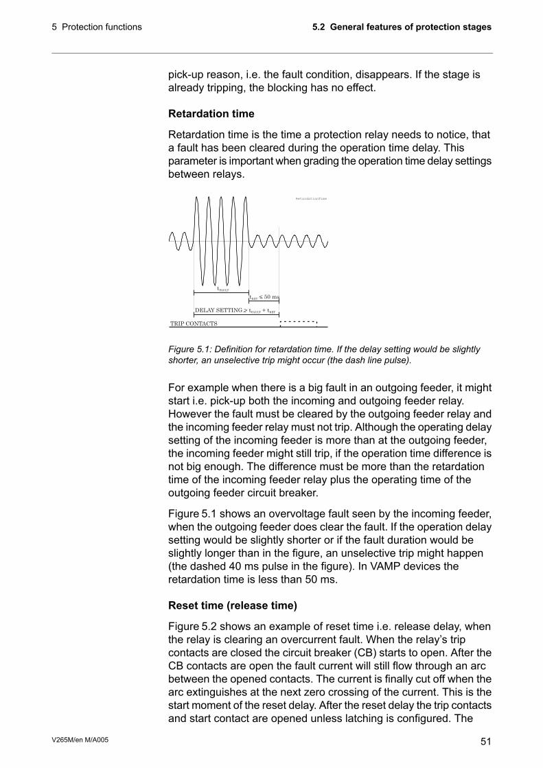
Retardation time
Retardation time is the time a protection relay needs to notice, thata fault has been cleared during the operation time delay. Thisparameter is important when grading the operation time delay settingsbetween relays.
DELAY SETTING > t + tFAULT RET
TRIP CONTACTS
t < 50 msRET
tFAULT
RetardationTime
Figure 5.1: Definition for retardation time. If the delay setting would be slightlyshorter, an unselective trip might occur (the dash line pulse).
For example when there is a big fault in an outgoing feeder, it mightstart i.e. pick-up both the incoming and outgoing feeder relay.However the fault must be cleared by the outgoing feeder relay andthe incoming feeder relay must not trip. Although the operating delaysetting of the incoming feeder is more than at the outgoing feeder,the incoming feeder might still trip, if the operation time difference isnot big enough. The difference must be more than the retardationtime of the incoming feeder relay plus the operating time of theoutgoing feeder circuit breaker.
Figure 5.1 shows an overvoltage fault seen by the incoming feeder,when the outgoing feeder does clear the fault. If the operation delaysetting would be slightly shorter or if the fault duration would beslightly longer than in the figure, an unselective trip might happen(the dashed 40 ms pulse in the figure). In VAMP devices theretardation time is less than 50 ms.
Reset time (release time)
Figure 5.2 shows an example of reset time i.e. release delay, whenthe relay is clearing an overcurrent fault. When the relay’s tripcontacts are closed the circuit breaker (CB) starts to open. After theCB contacts are open the fault current will still flow through an arcbetween the opened contacts. The current is finally cut off when thearc extinguishes at the next zero crossing of the current. This is thestart moment of the reset delay. After the reset delay the trip contactsand start contact are opened unless latching is configured. The
51V265M/en M/A005
5.2 General features of protection stages5 Protection functions

precise reset time depends on the fault size; after a big fault the resettime is longer. The reset time also depends on the specific protectionstage.
The maximum reset time for each stage is specified in Chapter 12.3Protection functions. For most stages it is less than 95 ms.
TRIP CONTACTS
tSET
tCB
tRESET
Figure 5.2: Reset time is the time it takes the trip or start relay contacts to openafter the fault has been cleared.
Hysteresis or dead band
When comparing a measured value against a pick-up value, someamount of hysteresis is needed to avoid oscillation near equilibriumsituation. With zero hysteresis any noise in the measured signal orany noise in themeasurement itself would cause unwanted oscillationbetween fault-on and fault-off situations.
> PICK UP
PICK UP LEVEL
hyst
ere
sis Hysteresis_GT
Figure 5.3: Behaviour of a greater than comparator. For example in overvoltagestages the hysteresis (dead band) acts according this figure.
< PICK UP
PICK UP LEVEL
hyst
ere
sis Hysteresis_LT
Figure 5.4: Behaviour of a less than comparator. For example in under-voltageand under frequency stages the hysteresis (dead band) acts according this figure.
V265M/en M/A00552
5 Protection functions5.2 General features of protection stages

5.3 Frequent start protection N> (66)The simplest way to start an asynchronous motor is just to switchthe stator windings to the supply voltages. However every such startwill heat up the motor considerably because the initial currents aresignificantly above the rated current.
If the motor manufacturer has defined the maximum number of startswithin an hour or/and the minimum time between two consecutivestarts this stage is easy to apply to prevent too frequent starts.
When current has been less than 10% of the motor nominal currentand then exceeds the value Motor start detection current of IST>(Stall protection stage), situation is recognized as a motor start. Afterthe recognition of the motor start if current drops to a less than 10% of the motor nominal current, stage considers motor to be stopped.
Frequent start protection stage will provide N> alarm signal whenthe second last start has been done and remains active until themaximum amount of motor starts are reached or one hour of time ispassed.
The N> motor start inhibit signal activates after starting the motorand remains active a period of time that is defined for parameter Mintime between motor starts. After the given time has passed, inhibitsignal returns to inactive state.
When start counter of stage reaches the value defined for Max. motorstarts/hour, N> motor start inhibit signal activates and remains activeuntil one hour has passed.
Frequent start protection stage correlation to output contacts isdefined in output matrix menu. See Chapter 8.4 Output matrix.Figure 5.5 shows an application.
53V265M/en M/A005
5.3 Frequent start protection N> (66)5 Protection functions

N> motor start inhibit
I> trip
N> alarm
I> start
T1 A1
VAMP relay
Output matrix
+
− −
+ +
M
STOP STARTOpen
Coil
Close
Coil
Figure 5.5: Application for preventing too frequent starting using the N> stage.The signal relay A1 has been configured to normal closed (NC) in device “relays”menu and is controlled by N> motor start inhibit signal. Whenever N> motor startinhibit signal becomes active, it prevents circuit breaker to be closed.
Table 5.1: Parameters of the frequent start protection N> (66)DescriptionValue/unitParameter
Stage statusDisabled/ EnabledStatusMeasured value
Start counterSCntr
Motor starts in last hourMot strs
Elapsed time from motor startMinT
Force flag for status forcing for test purposes. This isa common flag for all stages and output relays, too.This flag is automatically reset 5 minutes after the lastfront panel push button pressing
On/OffForce
Max. starts in one hourMot strsSetting values
Elapsed time from motor startMint
Stage statusStatus
Start counterSCntr
Max. motor start per hourSts/h
Min. interval between two consecutive startsMinInterval
Date and time of tripLOG1Recorded values
Motor starts / hourN.st / h
Elapsed time from motor startTimeFromSt
Number of total motor startsTot Mot Strs
Fault typeType
Alarm on eventAlr_onEvent Enabling
Alarm off EventAlr_off
Motor start disabledMoStrt_dis
Motor start enabledMotStrt_En
V265M/en M/A00554
5 Protection functions5.3 Frequent start protection N> (66)

5.4 Differential overcurrent protection ΔI>(87)The differential overcurrent protection comprises two separatelyadjustable stages, stage ΔI> and stage ΔI>>.
The differential protection is based on winding currents differencebetween IL and I’L side. In Yy0 connection measured currents arealso winding currents, see Figure 5.6. In motor and generatorapplications the connection group is always Yy0 and measuredcurrents are also winding currents.
Figure 5.6: Winding currents in connection group Yy0.
Bias current calculation is only used in protection stage ΔI>. Biascurrent describes the average current flow in transformer. Bias anddifferential currents are calculated individually for each phase.
5.Harm/
Fund
5.Harm
setting
Figure 5.7: Block diagram of the differential overcurrent stage ΔI>.
The stage ΔI> can be configured to operate as shown in Figure 5.8.This dual slope characteristic allows more differential current athigher currents before tripping.
55V265M/en M/A005
5.4 Differential overcurrent protection ΔI> (87)5 Protection functions

Figure 5.8: Example of differential overcurrent characteristics.
The stage also includes second harmonics blocking. The secondharmonic is calculated from winding currents. Harmonic ratio is:
100 x If2_Winding / If1_Winding [%].
Fast differential overcurrent stage ΔI>> does not include slopecharacteristics and second harmonics blocking.
V265M/en M/A00556
5 Protection functions5.4 Differential overcurrent protection ΔI> (87)

Table 5.2: Parameters of the differential overcurrent stages ΔI> (87)DescriptionValue/UnitParameter
Current difference valuexImotdIL1
dIL2
dIL3
Measured values(1
Setting value%lmotΔI>Setting values (2
Bias current start of slope 1xImotIbias1
Slope 1 setting%Slope1
Bias current start of slope 2xImotIbias2
Slope 2 setting%Slope2
2. harmonic blocking enable/disableOn/OffHarm2>
2. harmonic block limit%Harm2>
Cumulative trip counterTCntr
Fault type/single-phase fault e.g.: 1 – N = fault on phase L11-N, 2-N, 3-NType
Fault type/two-phase fault e.g.: 2 – 3 = fault between L2 and L31-2, 2-3, 1-3
Fault type/three-phase fault1-2-3
Max. value of fault differential current as compared to ImotxImotFlt
Value of bias current of faulted phase as compared to ImotxImotBias
1 s mean value of pre-fault phase currents IL1 – IL3xImotLoad
1) Measurement ranges are described in Table 12.1.
2) Setting ranges are described in Chapter 12.3.1 Differential protection.
Table 5.3: Parameters of the differential overcurrent stages ΔI>> (87)DescriptionValue/UnitParameter
Current difference valuexImotdIL1Measured values
dIL2
dIL3
Setting valuexImotΔI>>Setting values
Cumulative trip counterTCntrRecorded values
Fault type/single-phase fault e.g.: 1-N = fault on phase L11-N, 2-N, 3-NTypeRecorded values
Fault type/two-phase fault e.g.: 2-3 = fault between L2 and L31-2, 2-3, 1-3
Fault type/three-phase fault1-2-3
Max. value of fault differential current as compared to IMOTxImotFlt
1 s mean value of pre-fault phase currents IL1 – IL3xImotLoad
57V265M/en M/A005
5.4 Differential overcurrent protection ΔI> (87)5 Protection functions

Differential Protection using 6 CTs
X1-1X1-2
X1-3
X1-5
X1-4
X1-6
X1-11
X1-12
X1-13
X1-14
X1-15
X1-16
L1
L2
L3
M
Figure 5.9: VAMP 265M connected as a motor differential protection using 6 CTs.
In this application mode the settings in VAMP 265M relay’s menuSCALING should be set as described in the following section.
CT settings
Here the motor high and low side primary and secondary CT ratingsare set according to the actual CT ratios.
Set motor nominal current
Settings of the differential protection
ΔI> 87 function shall be enabled for differential protection.
ΔI> pick-up setting range is user selectable from 5 % to 50 % .
Slope 1 can be set to 5 %
IBIAS for start of slope 2 can be set to 3 x IN
Slope 2 can be set to 50 %
If CTs are saturating at through faults, the Slope 2 settings must bechanged accordingly.
ΔI> 2nd harmonic block enable can be set OFF (disabled).
ΔI> 2nd harmonic block limit can be disregarded and the factorydefault setting can be left intact.
V265M/en M/A00558
5 Protection functions5.4 Differential overcurrent protection ΔI> (87)

Motor differential protection using flux balancing principle
X1-1X1-2
M
X1-3
X1-5
X1-4
X1-6
X1-11
X1-12
X1-13X1-14
X1-15X1-16
Leave unconnected
L1
L2
L3
Figure 5.10: VAMP 265M connected as a motor differential protection using 3 corebalance CT’s connected using flux balancing principle.
In this application mode the settings in VAMP 265M relay’s menuSCALING should be set as described in the following section.
NOTE: If motor protection functions are used, connect the differentialconnection to the LV side CT inputs (I’L1, I’L2, I’L3).
CT Settings
CT Primary and CT Secondary settings shall be set according to theactual core balance CT ratios.
CT’ Primary and CT’ Secondary settings can be disregarded andthe factory default settings can be left intact.
Set motor nominal current
Settings of the differential protection
ΔI> 87 function shall be enabled for differential protection.
ΔI> pick-up setting range is user selectable from 5 % to 50 %.
Slope 1 can be set to 5 %
IBIAS for start of slope 2 can be set to 3 x IN
Slope 2 can be set to 50 %
ΔI> 2nd harmonic block enable can be set OFF (disabled).
ΔI> 2nd harmonic block limit can be disregarded and the factorydefault setting can be left intact.
59V265M/en M/A005
5.4 Differential overcurrent protection ΔI> (87)5 Protection functions

5.5 Overcurrent protection I> (50/51)Overcurrent protection is used against short circuit faults and heavyoverloads.
The overcurrent function measures the fundamental frequencycomponent of the phase currents. The protection is sensitive for thehighest of the three phase currents. Whenever this value exceedsthe user's pick-up setting of a particular stage, this stage picks upand a start signal is issued. If the fault situation remains on longerthan the user's operation delay setting, a trip signal is issued.
Two independent stages
There are two separately adjustable overcurrent stages: I>, I>>, I’>and I’>>. The first stage I> can be configured for definite time (DT)or inverse time operation characteristic (IDMT). The stage I>> hasdefinite time operation characteristic. By using the definite delay typeand setting the delay to its minimum, an instantaneous (ANSI 50)operation is obtained.
Figure 5.11 shows a functional block diagram of the I> overcurrentstage with definite time and inverse time operation time. Figure 5.12shows a functional block diagram of the I>> overcurrent stage withdefinite time operation delay.
Inverse operation time
Inverse delay means that the operation time depends on the amountthe measured current exceeds the pick-up setting. The bigger thefault current is the faster will be the operation. Accomplished inversedelays are available for the I> stage. The inverse delay types aredescribed in Chapter 5.17 Inverse time operation. The device willshow the currently used inverse delay curve graph on the local paneldisplay.
Inverse time limitation
The maximum measured secondary current is 50 x IN. This limitsthe scope of inverse curves with high pick-up settings. SeeChapter 5.17 Inverse time operation for more information.
Setting groups
There are two settings groups available for each stage. Switchingbetween setting groups can be controlled by digital inputs, virtualinputs (communication, logic) and manually.
V265M/en M/A00560
5 Protection functions5.5 Overcurrent protection I> (50/51)

Figure 5.11: Block diagram of the three-phase overcurrent stage I> and I'>.
Figure 5.12: Block diagram of the three-phase overcurrent stage I>> and I’>>.
Table 5.4: Parameters of the overcurrent stage I> and I’> (50/51)NoteDescriptionUnitValueParameter
-Current status of the stage-Status
-Blocked
FStart
FTrip
Estimated time to tripsTripTime
ClrCumulative start counterSCntr
ClrCumulative trip counterTCntr
SetActive setting group1 or 2SetGrp
SetDigital signal to select the active setting groupSGrpDI
None-
Digital inputDIx
Virtual inputVIx
LED indicator signalLEDx
Virtual outputVOx
61V265M/en M/A005
5.5 Overcurrent protection I> (50/51)5 Protection functions

NoteDescriptionUnitValueParameter
SetForce flag for status forcing for test purposes. This is a commonflag for all stages and output relays, too. This flag is automaticallyreset 5 minutes after the last front panel push button pressing.
Off
On
Force
The supervised value. Max. of IL1, IL2 and IL3AILmax
Current status of the stageStatus
Pick-up value scaled to primary valueAI>
SetPick-up settingxIMOTI>
SetDelay curve family:-Curve
Definite timeDT
Inverse time. See Chapter 5.17 Inverse time operation.IEC, IEEE,IEEE2, RI, PrgN
SetDelay type-Type
Definite timeDT
Inverse time. See Chapter 5.17 Inverse time operation.NI, VI, EI, LTI,Parameters
SetDefinite operation time (for definite time only)st>
SetInverse delay multiplier (for inverse time only)k>
Delay at 20xIsetsDly20x
Delay at 4xIsetsDly4x
Delay at 2xIsetsDly2x
Delay at 1xIsetsDly1x
Include Harmonics (Not in I'>stage)On/offIncHarm
Graphic delay curve picture (only local display)Delay curves
SetUser's constants for standard equations. Type=Parameters.Chapter 5.17 Inverse time operation.
A, B, C, D, E
Date and time of tripLOG1Recordedvalues Fault typeType
Fault currentxIMOTFlt
Pre-fault currentxIMOTLoad
Elapsed delay time%Edly
Active set group during faultSetGrp
Set = An editable parameter (password needed). C = Can be cleared to zero. F = Editable when force flag is on.
For details of setting ranges, see Chapter 12.3 Protection functions
Table 5.5: Parameters of the overcurrent stages I>>, I’>> (50/51)NoteDescriptionUnitValueParameter
-Current status of the stage-Status
-Blocked
FStart
FTrip
CCumulative start counterSCntr
CCumulative trip counterTCntr
SetActive setting group1 or 2SetGrp
V265M/en M/A00562
5 Protection functions5.5 Overcurrent protection I> (50/51)

NoteDescriptionUnitValueParameter
SetDigital signal to select the active setting groupSGrpDI
None-
Digital inputDIx
Virtual inputVIx
LED indicator signalLEDx
Virtual outputVOx
SetForce flag for status forcing for test purposes. This is a commonflag for all stages and output relays, too. Automatically reset by a5-minute timeout.
Off
On
Force
The supervised value. Max. of IL1, IL2 and IL3AILmax
Pick-up value scaled to primary valueAI>>, I>>>
SetPick-up settingxIMOTI>>, I>>>
SetDefinite operation timest>>, t>>>
SetInclude HarmonicsOn/offIncHarm
Set = An editable parameter (password needed), C = Can be cleared to zero, F = Editable when force flag is on.
For details of setting ranges, see Chapter 12.3 Protection functions
Recorded values of the latest eight faults
There is detailed information available of the eight latest faults: Timestamp, fault type, fault current, load current before the fault, elapseddelay and setting group.Table 5.6: Recorded values of the overcurrent stages (8 latest faults) I>, I>>,I>>> (50/51)
DescriptionUnitValueParameter
Time stamp of the recording, dateyyyy-mm-dd
Time stamp, time of dayhh:mm:ss.ms
Fault type
Ground fault
Ground fault
Ground fault
Two phase fault
Two phase fault
Two phase fault
Three phase fault
-
1-N
2-N
3-N
1-2
2-3
3-1
1-2-3
Type
Maximum fault currentxIMOTFlt
1 s average phase currents before the faultxIMOTLoad
Elapsed time of the operating time setting. 100% = trip%EDly
Active setting group during fault1, 2SetGrp
63V265M/en M/A005
5.5 Overcurrent protection I> (50/51)5 Protection functions

5.5.1 Remote controlled overcurrent scalingPick-up setting of the three over current stages can also be controlledremotely. In this case only two scaling coefficients are possible:100% (the scaling is inactive) and any configured value between10% - 200% (the scaling is active). When scaling is enabled allsettings of group one are copied to group two but the pick-up valueof group two is changed according the given value (10-200%).
• This feature can be enabled/disabled via VAMPSET or by usingthe local panel. When using VAMPSET the scaling can beactivated and adjusted in the “protection stage status 2” –menu.When using the local panel similar settings can be found fromthe “prot” -menu.
• It is also possible to change the scaling factor remotely by usingthe modbus TCP –protocol. When changing the scaling factorremotely value of 1% is equal to 1. Check the correct modbusaddress for this application from the VAMPSET or from thecommunication parameter list.
Figure 5.13: Remote scaling example.
In the Figure 5.13 can be seen the affect of remote scaling. Afterenabling group is changed from group one to group two and allsettings from group one are copied to group two. The difference isthat group two uses scaled pick-up settings.
NOTE: When remote scaling function is used, it replaces all the settings ofgroup 2. So this function cannot be used simultaneously with normalgroup change.
V265M/en M/A00564
5 Protection functions5.5 Overcurrent protection I> (50/51)

5.6 Stall protection IST> (48)The stall protection unit IST> measures the fundamental frequencycomponent of the phase currents.
Stage IST> can be configured for definite time or inverse timeoperation characteristic.
The stall protection stage protects the motor against prolongeddirect-on-line (DOL) starts caused by e.g. a stalled rotor, too highinertia of the load or too low voltage. This function is sensitive to thefundamental frequency component of the phase currents.
The IST> stage can be configured for definite operation time or inversetime operation characteristic. For a weak voltage supply the inversecharacteristics is useful allowing more start time when a voltage dropdecreases the start current and increases the start time. Equation5.1defines the inverse operation time. Figure 5.15 shows an exampleof the inverse characteristics.
Inverse operation time.T =
Rated start current of the motor “Nommotor start current”IMOTST. The default setting is 6.00xIMOT.
ISTART =
Measured currentIMEAS =
Maximum allowed start time “Inv. time coefficient” k> forthe motor at rated voltage.TSTART =
Equation 5.1:
start
meas
startT
I
IT
2
=
The pick-up setting “Motor start detection current” IST> is the startdetection level of the start current. While the current has been lessthan 10% of Imot and then within 200 milliseconds exceeds thesetting IST>, the stall protection stage starts to count the operationtime TSTART. When current drops below 120 % x IMOT the stallprotection stage releases. Stall protection is active only during thestarting of the motor.
&
t
³1
&
&
> ts trMAX
Istlohko
Motor nom.start current
Delay Definite / inversetime
Enable eventsInverse delay
Start
Trip
Registerevent
Registerevent
Im1
Im2
Im3
Block
Figure 5.14: Block diagram of the stall protection stage IST>.
65V265M/en M/A005
5.6 Stall protection IST> (48)5 Protection functions

Figure 5.15: Example of an inverse operation time delay of the stall protectionstage. If the measured current is less than the specified start current ISTART theoperation time will be longer than the specified start time TSTART and vice versa.
Table 5.7: Parameters of the stall protection stage IST> (48)DescriptionValue/unitParameter
Status of the stageStatusStatus
Cumulative start counterSCntr
Cumulative trip counterTCntr
Force flag for status forcing for test purposes. This isa common flag for all stages and output relays, too.This flag is automatically reset 5 minutes after the lastfront panel push button pressing.
ON/OffForce
Phase current IL, not settableAIlParameters
Status of stageStatus
Motor start detection current scaled to primary value,calculated by relay
AIst>
Motor start detection current. Must be less than initialmotor starting current.
xImotIst>
Nominal motor starting current scaled to primary value,calculated by relay
AImotSt
Nominal motor starting currentxImotImotSt
Operation charact./ definite timeDTType
Operation charact./ inverse timeInv
Operation time [s]St>
Time multiplier at inverse timeStInv>
Start and trip timeLogRecorded values
Maximum fault current.xImotFlt
Elapsed time of the operating time setting. 100% =trip
%EDly
V265M/en M/A00566
5 Protection functions5.6 Stall protection IST> (48)

5.6.1 Motor statusThere are three possible startus for a motor: stopped, starting orrunning.
• Motor stopped: Motor average current is less than 10% of themotor nominal current.
• Motor starting: To reach the starting position motor has to bestopped for least 500ms before starting. Motor average currenthas to increase above the motor start detection current (settingvalue) within 200ms. Motor will remain starting as long as theterms for turning into running condition are not filled.
• Motor running: Motor is able to turn into a running position fromboth stopped and starting position. Low limit for motor runningis 20% of the motors nominal and the high limit for motor runningis 120% of the motors nominal current.
Figure 5.16: Motor status via VAMPSETand local panel.
The status of the motor can be viewed via VAMPSET -software orby looking from the local panel of the relay (Mstat). Statuses Startingand running can be found from the output –and block matrix.Therefore it is possible to use these signals for tripping or indicationand for blocking purposes.
Figure 5.17: Motor status in output –and block matrix.
67V265M/en M/A005
5.6 Stall protection IST> (48)5 Protection functions

Softstart
Frequency converter drives and soft starter applications will notinitiate motor start signal due to the low current while starting motor.Motor will change directly from stopped to running position when thecurrent increases into a certain level.
Figure 5.18: The terms of soft start.
Normal starting sequence
As a default for the motor start detection, relay uses value of 6 timesmotor nominal. This value is editable.
Figure 5.19: The terms of normal starting sequence.
V265M/en M/A00568
5 Protection functions5.6 Stall protection IST> (48)
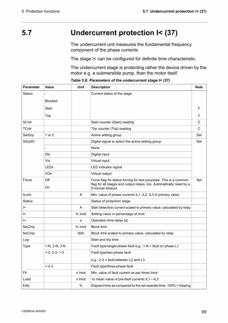
5.7 Undercurrent protection I< (37)The undercurrent unit measures the fundamental frequencycomponent of the phase currents.
The stage I< can be configured for definite time characteristic.
The undercurrent stage is protecting rather the device driven by themotor e.g. a submersible pump, than the motor itself.Table 5.8: Parameters of the undercurrent stage I< (37)
NoteDescriptionUnitValueParameter
-
-
F
F
Current status of the stage-
Blocked
Start
Trip
Status
CStart counter (Start) readingSCntr
CTrip counter (Trip) readingTCntr
SetActive setting group1 or 2SetGrp
SetDigital signal to select the active setting groupSGrpDI
None-
Digital inputDIx
Virtual inputVIx
LED indicator signalLEDx
Virtual outputVOx
SetForce flag for status forcing for test purposes. This is a commonflag for all stages and output relays, too. Automatically reset by a5-minute timeout.
Off
On
Force
Min. value of phase currents IL1, IL2, IL3 in primary valueAILmin
Status of protection stageStatus
Start detection current scaled to primary value, calculated by relayAI<
Setting value in percentage of Imot% ImotI<
Operation time delay [s]st<
Block limit% ImotNoCmp
Block limit scaled to primary value, calculated by relay60ANoCmp
Start and trip timeLog
Fault type/single-phase fault e.g.: 1-N = fault on phase L11-N, 2-N, 3-NType
Fault type/two-phase fault
e.g.: 2-3 = fault between L2 and L3
1-2, 2-3, 1-3
Fault type/three-phase fault1-2-3
Min. value of fault current as per times Imotx ImotFlt
1s mean value of pre-fault currents IL1—IL3x ImotLoad
Elapsed time as compared to the set operate time, 100% = tripping%Edly
69V265M/en M/A005
5.7 Undercurrent protection I< (37)5 Protection functions

5.8 Current unbalance protection I2>, I’2>(46)The current unbalance stage protects against unbalanced phasecurrents and single phasing. The protection is based on the negativesequence current. Both definite time and inverse time characteristicsare available. The inverse delay is based on Equation 5.2. Only thebase frequency components of the phase currents are used tocalculate the negative sequence value I2.
Inverse delay
The inverse delay is based on the following equation.
Operation timeT =
Delay multiplierK1 =
Measured and calculated negative sequence phasecurrent of fundamental frequency.
I2 =
Nominal current of the motorIMOT =
Pick-up setting I2> in pu. The maximum allowed degreeof unbalance.
K2 =
Example:15 sK1 =
22.9 % = 0.229 x IMOTI2 =
5 % = 0.05 x IMOTK2 =
Equation 5.2:
2
2
2
2
1
KI
I
KT
MOT
−
=
4.300
05.01
229.0
15
2
2=
−
=t
The operation time in this example will be five minutes.
More stages (definite time delay only)
If more than one definite time delay stages are needed for currentunbalance protection, the freely programmable stages can be used(Chapter 5.15 Programmable stages (99)).
Setting groups
There are two settings groups available. Switching between settinggroups can be controlled by digital inputs, virtual inputs(communication, logic) and manually.
V265M/en M/A00570
5 Protection functions5.8 Current unbalance protection I2>, I’2> (46)

01
10
100
1000
2
20
200
2000
5
50
500
20Negative sequence current I (%)2
CurrentUnbalanceChar
Op
erat
ion
tim
e (
s)
40 60 80 100
K = 1 s1
K = 50 s1
K = 2 %2
K = 2 %2
K = 40 %2
K = 40 %2
K = 70 %2
K = 70 %2
Figure 5.20: Inverse operation delay of current unbalance stage I2>. The longestdelay is limited to 1000 seconds (=16min 40s).
Table 5.9: Parameters of the current unbalance stage I2>, I’2> (46)NoteDescriptionUnitValueParameter
-Current status of the stage-Status
-Blocked
FStart
FTrip
CCumulative start counterSCntr
CCumulative trip counterTCntr
SetActive setting group1 or 2SetGrp
SetDigital signal to select the active setting groupSGrpDI
None-
Digital inputDIx
Virtual inputVIx
LED indicator signalLEDx
Virtual outputVOx
SetForce flag for status forcing for test purposes. This is acommon flag for all stages and output relays, too. Automat-ically reset by a 5-minute timeout.
Off
On
Force
The supervised value.% ImotI2/Imot
SetPick-up setting% ImotI2>
SetDefinite operation time (Type=DT)st>
SetDefinite timeDTType
Inverse time (Equation 5.2)INV
SetDelay multiplier (Type =INV)sK1
Set = An editable parameter (password needed). C = Can be cleared to zero. F = Editable when force flag is on.
For details of setting ranges, see Chapter 12.3 Protection functions
71V265M/en M/A005
5.8 Current unbalance protection I2>, I’2> (46)5 Protection functions

Recorded values of the latest eight faults
There is detailed information available of the eight latest faults: Timestamp, unbalance current, elapsed delay and setting group.Table 5.10: Recorded values of the current unbalance stage (8 latest faults)I2>, I’2> (46)
DescriptionUnitValueParameter
Time stamp of the recording, dateyyyy-mm-dd
Time stamp, time of dayhh:mm:ss.ms
Maximum unbalance current% ImotFlt
Elapsed time of the operating time setting. 100% = trip%EDly
Active setting group during the fault1
2
SetGrp
5.9 Phase reversal/incorrect phasesequence protection I2>> (47)The phase sequence stage prevents the motor from being startedin to wrong direction, thus protecting the load.
When the ratio between negative and positive sequence currentexceeds 80% and the average of three phase currents exceeds 0.2x IMOT in the start-up situation, the phase sequence stage starts andtrips after 100 ms after start-up.Table 5.11: Parameters of the incorrect phase sequence stage I2>> (47)
DescriptionValue/unitParameter
Neg. phase seq. current/pos. phase seq. current%I2/I1Measured value
Start counter (Start) readingSCntrRecorded values
Trip counter (Trip) readingTCntr
Max. value of fault current%Flt
Elapsed time as compared to the set operate time,100% = tripping
%EDly
V265M/en M/A00572
5 Protection functions5.9 Phase reversal/incorrect phase sequence protection I2>> (47)
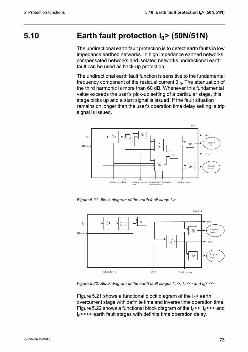
5.10 Earth fault protection I0> (50N/51N)The undirectional earth fault protection is to detect earth faults in lowimpedance earthed networks. In high impedance earthed networks,compensated networks and isolated networks undirectional earthfault can be used as back-up protection.
The undirectional earth fault function is sensitive to the fundamentalfrequency component of the residual current 3I0. The attenuation ofthe third harmonic is more than 60 dB. Whenever this fundamentalvalue exceeds the user's pick-up setting of a particular stage, thisstage picks up and a start signal is issued. If the fault situationremains on longer than the user's operation time delay setting, a tripsignal is issued.
Figure 5.21: Block diagram of the earth fault stage I0>
Figure 5.22: Block diagram of the earth fault stages I0>>, I0>>> and I0>>>>
Figure 5.21 shows a functional block diagram of the I0> earthovercurrent stage with definite time and inverse time operation time.Figure 5.22 shows a functional block diagram of the I0>>, I0>>> andI0>>>> earth fault stages with definite time operation delay.
73V265M/en M/A005
5.10 Earth fault protection I0> (50N/51N)5 Protection functions

Input signal selection
Each stage can be connected to supervise any of the following inputsand signals:
• Input I01 for all networks other than rigidly earthed.
• Input I02 for all networks other than rigidly earthed.
• Calculated signal I0Calc for rigidly and low impedance earthednetworks. I0Calc = IL1 + IL2 + IL3.
Intermittent earth fault detection
Short earth faults make the protection to start (to pick up), but willnot cause a trip. (Here a short fault means one cycle or more. Forshorter than 1 ms transient type of intermittent earth faults incompensated networks there is a dedicated stage I0INT> 67NI.) Whenstarting happens often enough, such intermittent faults can be clearedusing the intermittent time setting.
When a new start happens within the set intermittent time, theoperation delay counter is not cleared between adjacent faults andfinally the stage will trip.
Four independent undirectional earth fault overcurrent stages
There are four separately adjustable earth fault stages: I0>, I0>>,I0>>>, and I0>>>>. The first stage I0> can be configured for definitetime (DT) or inverse time operation characteristic (IDMT). The otherstages have definite time operation characteristic. By using thedefinite delay type and setting the delay to its minimum, aninstantaneous (ANSI 50N) operation is obtained.
Inverse operation time (I0> stage only)
Inverse delay means that the operation time depends on the amountthe measured current exceeds the pick-up setting. The bigger thefault current is the faster will be the operation. Accomplished inversedelays are available for the I0> stage. The inverse delay types aredescribed in Chapter 5.17 Inverse time operation. The device willshow a scaleable graph of the configured delay on the local paneldisplay.
Inverse time limitation
The maximum measured secondary residual current is 10 x I0N andmaximum measured phase current is 50 x IN. This limits the scopeof inverse curves with high pick-up settings. See Chapter5.17 Inversetime operation for more information.
V265M/en M/A00574
5 Protection functions5.10 Earth fault protection I0> (50N/51N)

Setting groups
There are two settings groups available for each stage. Switchingbetween setting groups can be controlled by digital inputs, virtualinputs (communication, logic) and manually.
Table 5.12: Parameters of the undirectional earth fault stage I0> (50N/51N)NoteDescriptionUnitValueParameter
-Current status of the stage-Status
-Blocked
FStart
FTrip
Estimated time to tripsTripTime
ClrCumulative start counterSCntr
ClrCumulative trip counterTCntr
SetActive setting group1 or 2SetGrp
SetDigital signal to select the active setting groupSGrpDI
None-
Digital inputDIx
Virtual inputVIx
LED indicator signalLEDx
Virtual outputVOx
SetForce flag for status forcing for test purposes. Thisis a common flag for all stages and output relays,too. Automatically reset by a 5-minute timeout.
Off
On
Force
The supervised value according the parameter "In-put" below.
puIo1, Io2, IoCalc,I’oCalc, Io1Peak,Io2Peak
Pick-up value scaled to primary valueAIo>
SetPick-up setting relative to the parameter "Input" andthe corresponding CT value
puIo>
SetDelay curve family:-Curve
Definite timeDT
Inverse time. Chapter 5.17 Inverse time operation.IEC, IEEE,IEEE2, RI, PrgN
SetDelay type.-Type
Definite timeDT
Inverse time. Chapter 5.17 Inverse time operation.NI, VI, EI, LTI,Parameters
SetDefinite operation time (for definite time only)st>
SetInverse delay multiplier (for inverse time only)k>
75V265M/en M/A005
5.10 Earth fault protection I0> (50N/51N)5 Protection functions

NoteDescriptionUnitValueParameter
SetX1:7 – 8. See Chapter 11 Connections.Io1Input
X1:9 – 10Io2
IL1 + IL2 + IL3IoCalc
I’L1 + I’L2 + I’L3I’oCalc
X1:7 – 8. peak mode (I0φ> only)Io1Peak
X1:9 – 10 peak mode (I0φ> only)Io2Peak
SetIntermittent timesIntrmt
Delay at 20 x IsetsDly20x
Delay at 4 x IsetsDly4x
Delay at 2 x IsetsDly2x
Delay at 1 x IsetDly1x
SetUser’s constants for standard equations.Type=Parameters. See Chapter 5.17 Inverse timeoperation.
A, B, C, D, E
Set = An editable parameter (password needed). C = Can be cleared to zero. F = Editable when force flag is on.
For details of setting ranges, see Chapter 12.3 Protection functions
Table 5.13: Parameters of the undirectional earth fault stage I0>>, I0>>>, I0>>>> (50N/51N)NoteDescriptionUnitValueParameter
-Current status of the stage-Status
-Blocked
FStart
FTrip
Estimated time to tripsTripTime
ClrCumulative start counterSCntr
ClrCumulative trip counterTCntr
SetActive setting group1 or 2SetGrp
SetDigital signal to select the active setting group-SgrpDI
None-
Digital inputDix
Virtual inputVix
LED indicator signalLEDx
Virtual outputVOx
SetForce flag for status forcing for test purposes. Thisis a common flag for all stages and output relays,too. Automatically reset by a 5-minute timeout.
Off
On
Force
The supervised value according the parameter “In-put” below.
puIo1
Io2
IoCalc
Pick-up value scaled to primary valueAIo>>, Io>>>, Io>>>>
SetPick-up setting relative to the parameter "Input" andthe corresponding CT value
puIo>>, Io>>>, Io>>>>
SetDefinite operation time (for definite time only)st>
V265M/en M/A00576
5 Protection functions5.10 Earth fault protection I0> (50N/51N)

NoteDescriptionUnitValueParameter
SetX1:7-8. See Chapter 11 Connections.Io1Input
X1:9-10Io2
IL1 + IL2 + IL3IoCalc
I’L1 + I’L2 + I’L3I’oCalc
Set = An editable parameter (password needed). C = Can be cleared to zero. F = Editable when force flag is on.
For details of setting ranges, see Chapter 12.3 Protection functions
Recorded values of the latest eight faults
There is detailed information available of the eight latest earth faults:Time stamp, fault current, elapsed delay and setting group.Table 5.14: Recorded values of the undirectional earth fault stages (8 latestfaults) I0>, I0>>, I0>>>, I0>>>> (50N/51N)
DescriptionUnitValueParameter
Time stamp of the recording, dateyyyy-mm-dd
Time stamp, time of dayhh:mm:ss.ms
Maximum earth fault currentpuFlt
Elapsed time of the operating time setting. 100% = trip%EDly
Active setting group during fault1, 2SetGrp
5.10.1 Earth fault faulty phase detection algorithmPhase recognition:
A zero sequence overcurrent has been detected.
Faulted phase/ phases are detected in 2 stage system.
1. Algorithm is using delta principle to detect the faulty phase/phases.
2. Algorithm confirms the faulty phase with neutral current anglecomparison to the suspected faulted phase.
Ideal grounded network:
When there is forward earth fault in phase L1, its current will increasecreating calculated or measured zero sequence current in phaseangle of 0 degrees. If there is reverse earth fault in phase L1, itscurrent will degrease creating calculated or measured zero sequencecurrent in phase angle of 180 degrees.
When there is forward earth fault in phase L2, its current will increasecreating calculated or measured zero sequence current in phaseangle of -120 degrees. If there is reverse earth fault in phase L2, itscurrent will degrease creating calculated or measured zero sequencecurrent in phase angle of 60 degrees.
77V265M/en M/A005
5.10 Earth fault protection I0> (50N/51N)5 Protection functions

When there is forward earth fault in phase L3, its current will increasecreating calculated or measured zero sequence current in phaseangle of 120 degrees. If there is reverse earth fault in phase L3 itscurrent will degrease creating calculated or measured zero sequencecurrent in phase angle of -60 degrees.
Implementation:
When faulty phase is recognized, it will be recorded in 50N protectionfault log (also in event list and alarm screen). This faulted phase anddirection recording function has a tick box for enabling/disabling inprotection stage settings. For compensated network, this is not a100% reliable algorithm because it depends on the networkcompensation degree. So for compensated networks this featurecan be turned off so it will not cause confusion. For high impedanceearthed networks, there will be drop down menu in both settinggroups to choose between RES/CAP. RES is default and it is forearthed networks.When CAP is chosen, the Io angle will be correctedto inductive direction 90 degrees and after that faulty phase detectionis made.
Possible outcomes and conditions for those detections:
• FWD L1Phase L1 increases above the set limit and two other phasesremain inside the set (delta) limit. Io current angle is +/- 60degrees from L1 phase angle.
• FDW L2Phase L2 increases above the set limit and two other phasesremain inside the set (delta) limit. Io current angle is +/- 60degrees from L2 phase angle.
• FDW L3Phase L3 increases above the set limit and two other phasesremain inside the set (delta) limit. Io current angle is +/- 60degrees from L3 phase angle.
• FWD L1-L2Phase L1 and L2 increase above the set limit and phase L3remains inside the set (delta) limit. Io current angle is betweenL1 and L2 phase angles.
• FWD L2-L3Phase L2 and L3 increase above the set limit and phase L1remains inside the set (delta) limit. Io current angle is betweenL2 and L3 phase angles.
• FWD L3-L1Phase L3 and L1 increase above the set limit and phase L2remains inside the set (delta) limit. Io current angle is betweenL3 and L3 phase angles.
V265M/en M/A00578
5 Protection functions5.10 Earth fault protection I0> (50N/51N)

• FWD L1-L2-L3All three phase currents increase above the set delta limit.
• REV 1 (any one phase)One phase decreases below the set delta limit and other twophases remain inside the delta limit.
• REV 2 (any two phase)Two phases decrease below the set delta limit and third phaseremains inside the delta limit.
• REV 3 (all three phases)All three phase currents decrease below the set delta limit.
Below are simulated different fault scenarios:
Figure 5.23: Phase L1 forward
Figure 5.24: Phase L2 forward
Figure 5.25: Phase L3 forward
79V265M/en M/A005
5.10 Earth fault protection I0> (50N/51N)5 Protection functions

5.11 Thermal overload protection T> (49)The thermal overload function protects the transformer againstexcessive temperatures.
Thermal model
The temperature is calculated using rms values of phase currentsand a thermal model according IEC 60255-8. The rms values arecalculated using harmonic components up to the 15th.
22
22
lnaI
IIt
P
−
−⋅=τ
Trip time:
IkkaMOT
alarm⋅⋅⋅=Θ (Alarm 60% = 0.6)
Alarm:
MOTIkka ⋅⋅=
Θ
Trip:
22
2
lnIa
ICt
P
−
⋅⋅=τ
τ
Release time:
MOTIka ××= 95.0
Trip release:
IkaMOT
alarm×××= 95.0 (Alarm 60% = 0.6)Start release:
Operation timeT =
Thermal time constant tau (Setting value)=
Natural logarithm functionln =
Measured rms phase current (the max. value ofthree phase currents)
I =
Preload current,
MOTPIkI ××= θ (If temperature
rise is 120%(θ = 1.2). This parameter is thememory of the algorithm and corresponds to theactual temperature rise.
Ip =
Overload factor (Maximum continuous current),i.e. service factor.(Setting value)
k =
Ambient temperature factor (Permitted current dueto tamb).
kΘ =
The rated currentIMOT =
Relay cooling time constant (Setting value) τC =
V265M/en M/A00580
5 Protection functions5.11 Thermal overload protection T> (49)
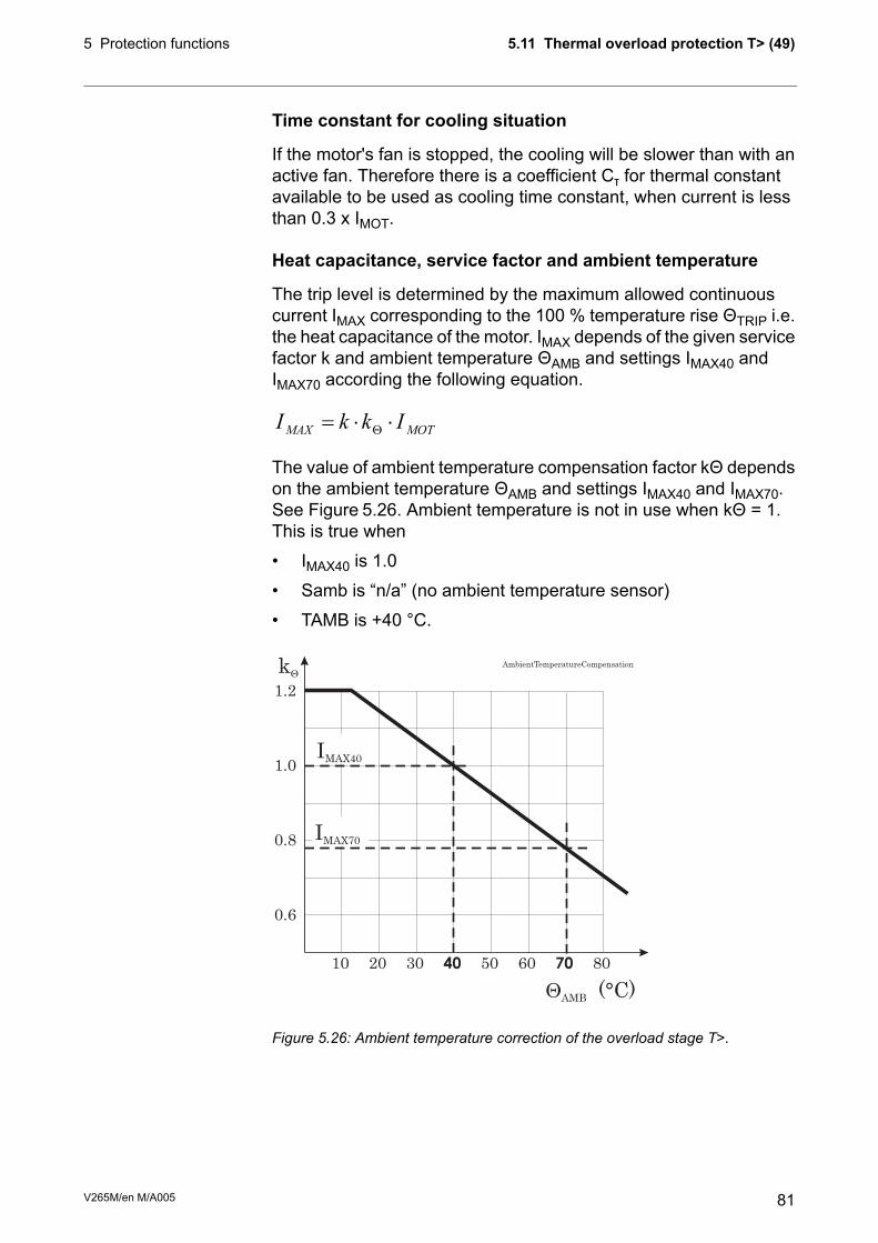
Time constant for cooling situation
If the motor's fan is stopped, the cooling will be slower than with anactive fan. Therefore there is a coefficient Cτ for thermal constantavailable to be used as cooling time constant, when current is lessthan 0.3 x IMOT.
Heat capacitance, service factor and ambient temperature
The trip level is determined by the maximum allowed continuouscurrent IMAX corresponding to the 100 % temperature rise ΘTRIP i.e.the heat capacitance of the motor. IMAX depends of the given servicefactor k and ambient temperature ΘAMB and settings IMAX40 andIMAX70 according the following equation.
MOTMAXIkkI ⋅⋅=
Θ
The value of ambient temperature compensation factor kΘ dependson the ambient temperature ΘAMB and settings IMAX40 and IMAX70.See Figure 5.26. Ambient temperature is not in use when kΘ = 1.This is true when
• IMAX40 is 1.0
• Samb is “n/a” (no ambient temperature sensor)
• TAMB is +40 °C.
kQ
IMAX70
IMAX40
QAMB (°C)
AmbientTemperatureCompensation
0.6
10 20 30 40 50 60 70 80
0.8
1.0
1.2
Figure 5.26: Ambient temperature correction of the overload stage T>.
81V265M/en M/A005
5.11 Thermal overload protection T> (49)5 Protection functions

Example of a behaviour of the thermal model
Figure 5.26 shows an example of the thermal model behaviour. Inthis example = 30 minutes, k = 1.06 and kΘ = 1 and the currenthas been zero for a long time and thus the initial temperature rise is0 %. At time = 50 minutes the current changes to 0.85 x IMOT andthe temperature rise starts to approach value (0.85/1.06)2 = 64 %according the time constant. At time = 300 min, the temperature isabout stable, and the current increases to 5 % over the maximumdefined by the rated current and the service factor k. The temperaturerise starts to approach value 110 %. At about 340 minutes thetemperature rise is 100 % and a trip follows.
Initial temperature rise after restart
When the device is switched on, an initial temperature rise of 70 %is used. Depending of the actual current, the calculated temperaturerise then starts to approach the final value.
Alarm function
The thermal overload stage is provided with a separately settablealarm function. When the alarm limit is reached the stage activatesits start signal.
Figure 5.27: Example of the thermal model behaviour.
V265M/en M/A00582
5 Protection functions5.11 Thermal overload protection T> (49)
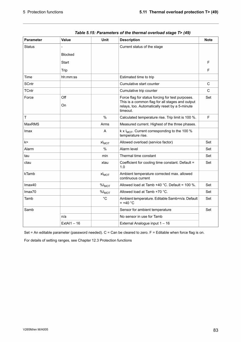
Table 5.15: Parameters of the thermal overload stage T> (49)NoteDescriptionUnitValueParameter
-Current status of the stage-Status
-Blocked
FStart
FTrip
Estimated time to triphh:mm:ssTime
CCumulative start counterSCntr
CCumulative trip counterTCntr
SetForce flag for status forcing for test purposes.This is a common flag for all stages and outputrelays, too. Automatically reset by a 5-minutetimeout.
Off
On
Force
FCalculated temperature rise. Trip limit is 100 %.%T
Measured current. Highest of the three phases.ArmsMaxRMS
k x IMOT. Current corresponding to the 100 %temperature rise.
AImax
SetAllowed overload (service factor)xIMOTk>
SetAlarm level%Alarm
SetThermal time constantmintau
SetCoefficient for cooling time constant. Default =1.0
xtauctau
Ambient temperature corrected max. allowedcontinuous current
xIMOTkTamb
SetAllowed load at Tamb +40 °C. Default = 100 %.%IMOTImax40
SetAllowed load at Tamb +70 °C.%IMOTImax70
SetAmbient temperature. Editable Samb=n/a. Default= +40 °C
°CTamb
SetSensor for ambient temperatureSamb
No sensor in use for Tambn/a
External Analogue input 1 – 16ExtAI1 – 16
Set = An editable parameter (password needed). C = Can be cleared to zero. F = Editable when force flag is on.
For details of setting ranges, see Chapter 12.3 Protection functions
83V265M/en M/A005
5.11 Thermal overload protection T> (49)5 Protection functions

5.12 Magnetishing inrush If2 > (68F2)This stage is mainly used to block other stages. The ratio betweenthe second harmonic component and the fundamental frequencycomponent is measured on all the phase currents. When the ratioin any phase exceeds the setting value, the stage gives a start signal.After a settable delay, the stage gives a trip signal.
The start and trip signals can be used for blocking the other stages.
The trip delay is irrelevant if only the start signal is used for blocking.
The trip delay of the stages to be blocked must be more than 60 msto ensure a proper blocking.
&
t
&
&
Im1
Im2
Im3MAX
2ndHarm
ts tr> Start
Trip
Registerevent
Registerevent
Setting2.Harm
Block
Delay Enable events
Figure 5.28: Block diagram of the magnetishing inrush stage.
Table 5.16: Setting parameters of magnetishing inrush blocking (68F2)DescriptionDefaultUnitValueParameter
Setting value If2/Ifund10%10 – 100If2>
Definite operating time0.05s0.05 – 300.0t_f2
Start on eventEnabled-Enabled; DisabledS_On
Start off eventEnabled-Enabled; DisabledS_Off
Trip on eventEnabled-Enabled; DisabledT_On
Trip off eventEnabled-Enabled; DisabledT_Off
Table 5.17: Measured and recorded values of magnetishing inrush blocking(68F2)
DescriptionUnitValueParameter
2. harmonic of IL1, proportional to the fundamental value ofIL1
%IL1H2.Measured values
2. harmonic of IL2%IL2H2.
2. harmonic of IL3%IL3H2.
The max. fault value%FltRecorded values
Elapsed time as compared to the set operating time; 100%= tripping
%EDly
V265M/en M/A00584
5 Protection functions5.12 Magnetishing inrush If2 > (68F2)

5.13 Transformer over exicitation If5> (68F5)Overexiting for example a transformer creates odd harmonics. Thisover exicitation stage can be used detect overexcitation. This stagecan also be used to block some other stages.
The ratio between the over exicitation component and thefundamental frequency component is measured on all the phasecurrents. When the ratio in any phase exceeds the setting value, thestage gives a start signal. After a settable delay, the stage gives atrip signal.
The trip delay of the stages to be blocked must be more than 60 msto ensure a proper blocking.Table 5.18: Setting parameters of over exicitation blocking (68F5)
DescriptionDefaultUnitValueParameter
Setting value If2/Ifund10%10 – 100If5>
Definite operating time0.05s0.05 – 300.0t_f5
Start on eventEnabled-Enabled; DisabledS_On
Start off eventEnabled-Enabled; DisabledS_Off
Trip on eventEnabled-Enabled; DisabledT_On
Trip off eventEnabled-Enabled; DisabledT_Off
Table 5.19: Measured and recorded values of over exicitation blocking (68F5)DescriptionUnitValueParameter
5. harmonic of IL1, proportional to the fundamentalvalue of IL1
%IL1H5.Measured values
5. harmonic of IL2%IL2H5.
5. harmonic of IL3%IL3H5.
The max. fault value%FltRecorded values
Elapsed time as compared to the set operating time;100% = tripping
%EDly
85V265M/en M/A005
5.13 Transformer over exicitation If5> (68F5)5 Protection functions

5.14 Circuit breaker failure protection CBFP(50BF)The circuit breaker failure protection can be used to trip any upstreamcircuit breaker (CB), if the fault has not disappeared within a giventime after the initial trip command. A different output contact of thedevice must be used for this backup trip.
The operation of the circuit-breaker failure protection (CBFP) is basedon the supervision of the signal to the selected trip relay and the timethe fault remains on after the trip command.
If this time is longer than the operating time of the CBFP stage, theCBFP stage activates another output relay, which will remainactivated until the primary trip relay resets.
The CBFP stage is supervising all the protection stages using thesame selected trip relay, since it supervises the control signal of thisdevice. See Chapter 8.4 Output matrixTable 5.20: Parameters of the circuit breaker failure stage CBFP (50BF)
NoteDescriptionUnitValueParameter
-
-
F
F
Current status of the stage-
Blocked
Start
Trip
Status
CCumulative start counterSCntr
CCumulative trip counterTCntr
SetForce flag for status forcing for test purposes. This isa common flag for all stages and output relays, too.Automatically reset by a 5-minute timeout.
Off
On
Force
SetThe supervised output relay*).Cbrelay
Relay T11
Relay T22
SetDefinite operation time.st>
*) This setting is used by the circuit breaker condition monitoring, too. See Chapter 6.4 Circuit breaker condition monitoring.
Set = An editable parameter (password needed). C = Can be cleared to zero. F = Editable when force flag is on.
For details of setting ranges, see Chapter 12.3 Protection functions
Recorded values of the latest eight faults
There are detailed information available of the eight latest faults:Time stamp and elapsed delay.
V265M/en M/A00586
5 Protection functions5.14 Circuit breaker failure protection CBFP (50BF)

Table 5.21: Recorded values of the circuit breaker failure stage (8 latestfaults) CBFP (50BF)
DescriptionUnitValueParameter
Time stamp of the recording, dateyyyy-mm-dd
Time stamp, time of dayhh:mm:ss.ms
Elapsed time of the operating time setting. 100% = trip%EDly
5.15 Programmable stages (99)For special applications the user can built own protection stages byselecting the supervised signal and the comparison mode.
The following parameters are available:
• PriorityIf operation times less than 80 milliseconds are needed select10 ms. For operation times under one second 20 ms isrecommended. For longer operation times and THD signals 100ms is recommended.
• Coupling AThe name of the supervised signal in “>” and “<” modes (seetable below). Also the name of the supervised signal 1 in “Diff”and “AbsDiff” modes.
• Coupling BThe name of the supervised signal 2 in “Diff” and “AbsDiff”modes.
• Compare conditionCompare mode. ‘>’ for over or ‘<’ for under comparison, “Diff”and “AbsDiff” for comparing Coupling A and Coupling B.
• Pick-upLimit of the stage. The available setting range and the unitdepend on the selected signal.
• Operation delayDefinite time operation delay
• HysteresisDead band (hysteresis)
• No Compare limit for mode <Only used with compare mode under (‘<’). This is the limit to startthe comparison. Signal values under NoCmp are not regardedas fault.
87V265M/en M/A005
5.15 Programmable stages (99)5 Protection functions

Table 5.22: Available signals to be supervised by the programmable stagesTask intervalAlarm stages link signals
100msIL1 – IL3, IL1W – IL3W, I’L1W – I’L3W, IL, I’L
Io1, Io2, Iocalc, I’oCalc, I1, I2, I2/I1, I2/In, I’1, I’2, I’2/I’1, I’2/In,dIL1, dIL2, dIL3
THDIL1, THDIL2, THDIL3
Virtual analog inputs 1, 2,3, 4, 5 (GOOSE)
VAI1, VAI2, VAI3, VAI4, VAI5
Eight independent stages
The device has eight independent programmable stages. Eachprogrammable stage can be enabled or disabled to fit the intendedapplication.
Setting groups
There are two settings groups available. Switching between settinggroups can be controlled by digital inputs, virtual inputs (mimicdisplay, communication, logic) and manually.
There are two identical stages available with independent settingparameters.
V265M/en M/A00588
5 Protection functions5.15 Programmable stages (99)

Table 5.23: Parameters of the programmable stages PrgN (99)NoteDescriptionUnitValueParameter
-
-
F
F
Current status of the stage-
Blocked
Start
Trip
Status
CCumulative start counterSCntr
CCumulative trip counterTCntr
SetActive setting group1 or 2SetGrp
SetDigital signal to select the active setting groupSGrpDI
None-
Digital inputDIx
Virtual inputVIx
LED indicator signalLEDx
Virtual outputVOx
SetForce flag for status forcing for test purposes. This is acommon flag for all stages and output relays, too. Automat-ically reset by a 5-minute timeout.
Off
On
Force
Name for the supervised signalSee Table 5.22Link
Value of the supervised signalSee Table 5.22
SetMode of comparisonCmp
Over protection>
Under protection<
DifferenceDiff
Absolut differenceAbsDiff
Pick up value scaled to primary levelPickup
SetPick up setting in pupuPickup
SetDefinite operation time.st
SetDead band setting%Hyster
SetMinimum value to start under comparison. (Mode='<')puNoCmp
Set = An editable parameter (password needed). C = Can be cleared to zero. F = Editable when force flag is on.
Recorded values of the latest eight faults
There is detailed information available of the eight latest faults: Timestamp, fault value and elapsed delay.Table 5.24: Recorded values of the programmable stages PrgN (99)
DescriptionUnitValueParameter
Time stamp of the recording, dateyyyy-mm-dd
Time stamp, time of dayhh:mm:ss.ms
Fault valuepuFlt
Elapsed time of the operating time setting. 100% = trip%EDly
Active setting group during fault1, 2SetGrp
89V265M/en M/A005
5.15 Programmable stages (99)5 Protection functions

5.16 Arc fault protection (50ARC/50NARC)optional
NOTE: This protection function needs optional hardware in slot X6. Moredetails of the hardware can be found in Chapter 11.4 Optional twochannel arc protection card and Table 12.9).
Arc protection is used for fast arc protection. The function is basedon simultaneous light and current measurement. Special arc sensorsare used to measure the light of an arc.
Stages for arc faults
There are four separate stages for the various current inputs:
for phase-to-phase arc faults. Current inputs IL1, IL2, IL3are used.
ArcI>:
for phase-to-phase arc faults. Current inputs I’L1, I’L2,I’L3 are used.
ArcI’>:
for phase-to-earth arc faults. Current input I01 is used.ArcI01>:
for phase-to-earth arc faults. Current input I02 is used.ArcI02>:
Light channel selection
The light information source to the stages can be selected from thefollowing list.
• - : No sensor selected. The stage will not work.
• S1: Light sensor S1.
• S2: Light sensor S2.
• S1/S2: Either one of the light sensors S1 or S2.
• BI: Binary input of the arc card. 48 Vdc.
• S1/BI: Light sensor S1 or the binary input.
• S2/BI: Light sensor S2 or the binary input.
• S1/S2/BI: Light sensor S1 or S2 or the binary input.
Binary input
The binary input (BI) on the arc option card (see Chapter 11.4Optional two channel arc protection card) can be used to get thelight indication from another relay to build selective arc protectionsystems.
The BI signal can also be connected to any of the output relays, BO,indicators etc. offered by the output matrix (see Chapter 8.4 Outputmatrix). BI is a dry input for 48 Vdc signal from binary outputs ofother VAMP devices or dedicated arc protection devices by VAMP.
V265M/en M/A00590
5 Protection functions5.16 Arc fault protection (50ARC/50NARC) optional

Binary output
The binary output (BO) on the arc option card (see Chapter 11.4Optional two channel arc protection card) can be used to give thelight indication signal or any other signal or signals to another relay'sbinary input to build selective arc protection systems.
Selection of the BO connected signal(s) is done with the output matrix(see Chapter 8.4 Output matrix). BO is an internally wetted 48 Vdcsignal for BI of other VAMP relays or dedicated arc protection devicesby VAMP.
Delayed light indication signal
Relay output matrix has a delayed light indication output signal(Delayed Arc L>) available for building selective arc protectionsystems. Any light source combination and a delay can be configuredstarting from 0.01 s to 0.15 s. The resulting signal is available in theoutput matrix to be connected to BO, output relays etc.
Pick up scaling
The per unit (pu) values for pick up setting are based on the currenttransformer values.
1 pu = 1 x IN = rated phase current CT valueArcI>:
1 pu = 1 x I'N = rated phase current CT valueArcI'>:
1 pu = 1 x I01N = rated residual current CT value for inputI01.
ArcI01>:
1 pu = 1 x I02N = rated residual current CT value for inputI02.
ArcI02>:
Table 5.25: Parameters of arc protection stages ArcI>, ArcI’>, ArcI01>, ArcI02>(50ARC/50NARC)
NoteDescriptionUnitValueParameter
-Current status of the stage-Status
FLight detected according ArcINStart
FLight and overcurrent detectedTrip
CCumulative light indication counter. S1, S2 or BI.LCntr
CCumulative light indication counter for the selected in-puts according parameter ArcIN
SCntr
CCumulative trip counterTCntr
SetForce flag for status forcing for test purposes. This is acommon flag for all stages and output relays, too.Automatically reset by a 5-minute timeout.
Off
On
Force
91V265M/en M/A005
5.16 Arc fault protection (50ARC/50NARC) optional5 Protection functions
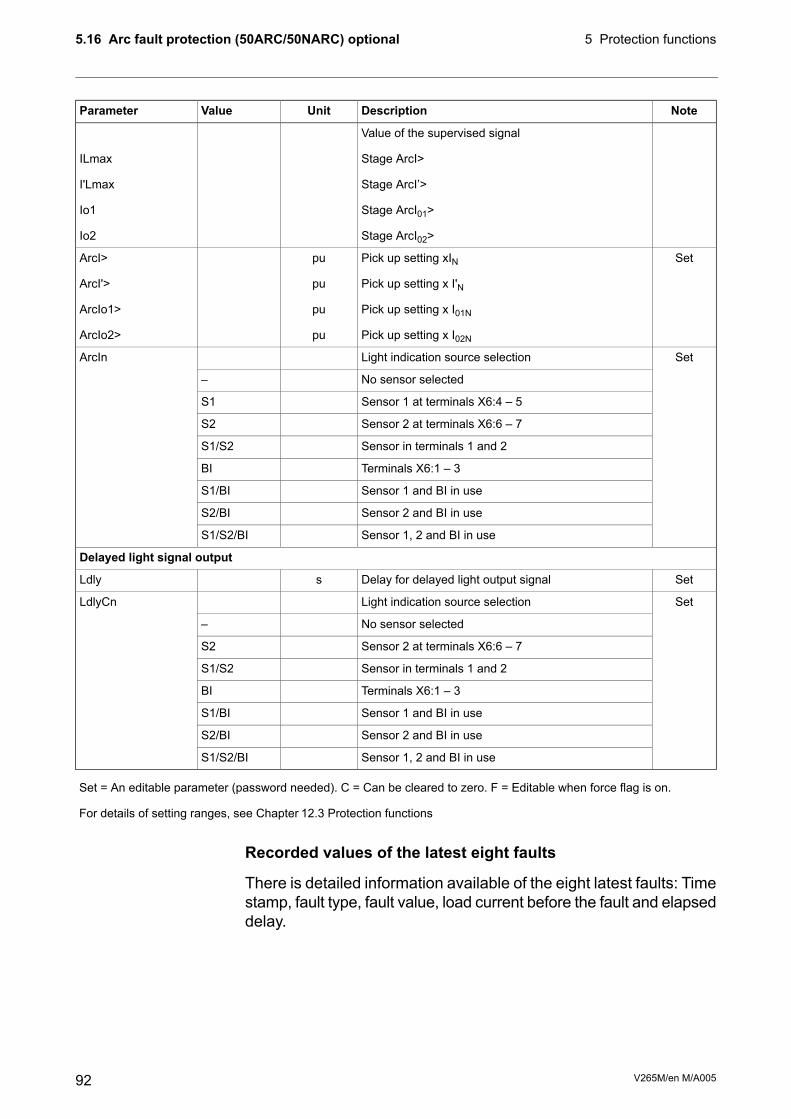
NoteDescriptionUnitValueParameter
Value of the supervised signal-
Stage ArcI>ILmax
Stage ArcI’>I'Lmax
Stage ArcI01>Io1
Stage ArcI02>Io2
SetPick up setting xINpuArcI>
Pick up setting x I'NpuArcI'>
Pick up setting x I01NpuArcIo1>
Pick up setting x I02NpuArcIo2>
SetLight indication source selectionArcIn
No sensor selected–
Sensor 1 at terminals X6:4 – 5S1
Sensor 2 at terminals X6:6 – 7S2
Sensor in terminals 1 and 2S1/S2
Terminals X6:1 – 3BI
Sensor 1 and BI in useS1/BI
Sensor 2 and BI in useS2/BI
Sensor 1, 2 and BI in useS1/S2/BI
Delayed light signal output
SetDelay for delayed light output signalsLdly
SetLight indication source selectionLdlyCn
No sensor selected–
Sensor 2 at terminals X6:6 – 7S2
Sensor in terminals 1 and 2S1/S2
Terminals X6:1 – 3BI
Sensor 1 and BI in useS1/BI
Sensor 2 and BI in useS2/BI
Sensor 1, 2 and BI in useS1/S2/BI
Set = An editable parameter (password needed). C = Can be cleared to zero. F = Editable when force flag is on.
For details of setting ranges, see Chapter 12.3 Protection functions
Recorded values of the latest eight faults
There is detailed information available of the eight latest faults: Timestamp, fault type, fault value, load current before the fault and elapseddelay.
V265M/en M/A00592
5 Protection functions5.16 Arc fault protection (50ARC/50NARC) optional

Table 5.26: Recorded values of the arc protection stagesDescriptionUnitValueParameter
Time stamp of the recording, dateyyyy-mm-dd
Time stamp, time of dayhh:mm:ss.ms
Fault type value. Only for ArcI> stage.puType
Fault valuepuFlt
Pre fault current. Only for ArcI> stage.puLoad
Elapsed time of the operating time setting. 100% = trip%EDly
93V265M/en M/A005
5.16 Arc fault protection (50ARC/50NARC) optional5 Protection functions

5.17 Inverse time operationThe inverse time operation - i.e. inverse delay minimum time (IDMT)type of operation - is available for several protection functions. Thecommon principle, formulae and graphic representations of theavailable inverse delay types are described in this chapter.
Inverse delay means that the operation time depends on themeasured real time process values during a fault. For example withan overcurrent stage using inverse delay a bigger a fault currentgives faster operation. The alternative to inverse delay is definitedelay. With definite delay a preset time is used and the operationtime does not depend on the size of a fault.
Stage specific inverse delay
Some protection functions have their own specific type of inversedelay. Details of these dedicated inverse delays are described withthe appropriate protection function.
Operation modes
There are three operation modes to use the inverse timecharacteristics:
• Standard delaysUsing standard delay characteristics by selecting a curve family(IEC, IEEE, IEEE2, RI) and a delay type (Normal inverse, Veryinverse etc). See Chapter 5.17.1 Standard inverse delays IEC,IEEE, IEEE2, RI.
• Standard delay formulae with free parametersselecting a curve family (IEC, IEEE, IEEE2) and defining one'sown parameters for the selected delay formula. This mode isactivated by setting delay type to ‘Parameters’, and then editingthe delay function parameters A – E. See Chapter 5.17.2 Freeparameterization using IEC, IEEE and IEEE2 equations.
• Fully programmable inverse delay characteristicsBuilding the characteristics by setting 16 [current, time] points.The relay interpolates the values between given points with 2nddegree polynomials. This mode is activated by setting curvefamily to ‘PrgN’'. There are maximum three differentprogrammable curves available at the same time. Eachprogrammed curve can be used by any number of protectionstages. See Chapter 5.17.3 Programmable inverse time curves.
Local panel graph
The device will show a graph of the currently used inverse delay onthe local panel display. Up and down keys can be used for zooming.Also the delays at 20 x ISET, 4 x ISET and 2 x ISET are shown.
V265M/en M/A00594
5 Protection functions5.17 Inverse time operation

Inverse time setting error signal
If there are any errors in the inverse delay configuration theappropriate protection stage will use definite time delay.
There is a signal ‘Setting Error’ available in output matrix, whichindicates three different situations:
1. Settings are currently changed with VAMPSET or local panel,and there is temporarily an illegal combination ofcurve/delay/points. For example if previous settings were IEC/NIand then curve family is changed to IEEE, the setting error willactive, because there is no NI type available for IEEE curves.After changing valid delay type for IEEE mode (for example MI),the ‘Setting Error’ signal will release.
2. There are errors in formula parameters A – E, and the device isnot able to build the delay curve
3. There are errors in the programmable curve configuration andthe device is not able to interpolate values between the givenpoints.
Limitation
The maximum measured phase current is 50 x IN and the maximumdirectly measured earth fault current is 5 x I0N. This limits the scopeof inverse curves when the setting is more than 2.5 x IN (overcurrentstages and earth fault stages using I0Calc input) or 0.25 x I01N (earthfault stages using I01 input or I02 input). The IN and I01N and I02Ndepend on the order code (See Chapter 14 Order information). Thetable below gives the limit values in secondary amperes.
Example of limitation
CT = 750 / 5
IN = 577 A
CT0 = 100 / 1 (a cable CT for I0)
Secondary scaled IMOTSEC is now 3.85 A
For 5 A CT secondaries and 1 A residual current inputs VAMP relayVAMP 265-5D7AAA is used. It has 5 A phase current inputs and 1A residual inputs.
For overcurrent stage I> the table below gives 12.5 A. Thus themaximum setting for I> stage giving full inverse delay range is 12.5A / 3.85 A = 3.25 x IMOT.
For earth fault stage I0> and input I01 the table below gives 0.25 A.Thus the maximum setting for I0> stage giving full inverse delayrange is 0.25 A / 1 A = 0.25 pu. This equals a 25 A primary earthfault current.
95V265M/en M/A005
5.17 Inverse time operation5 Protection functions
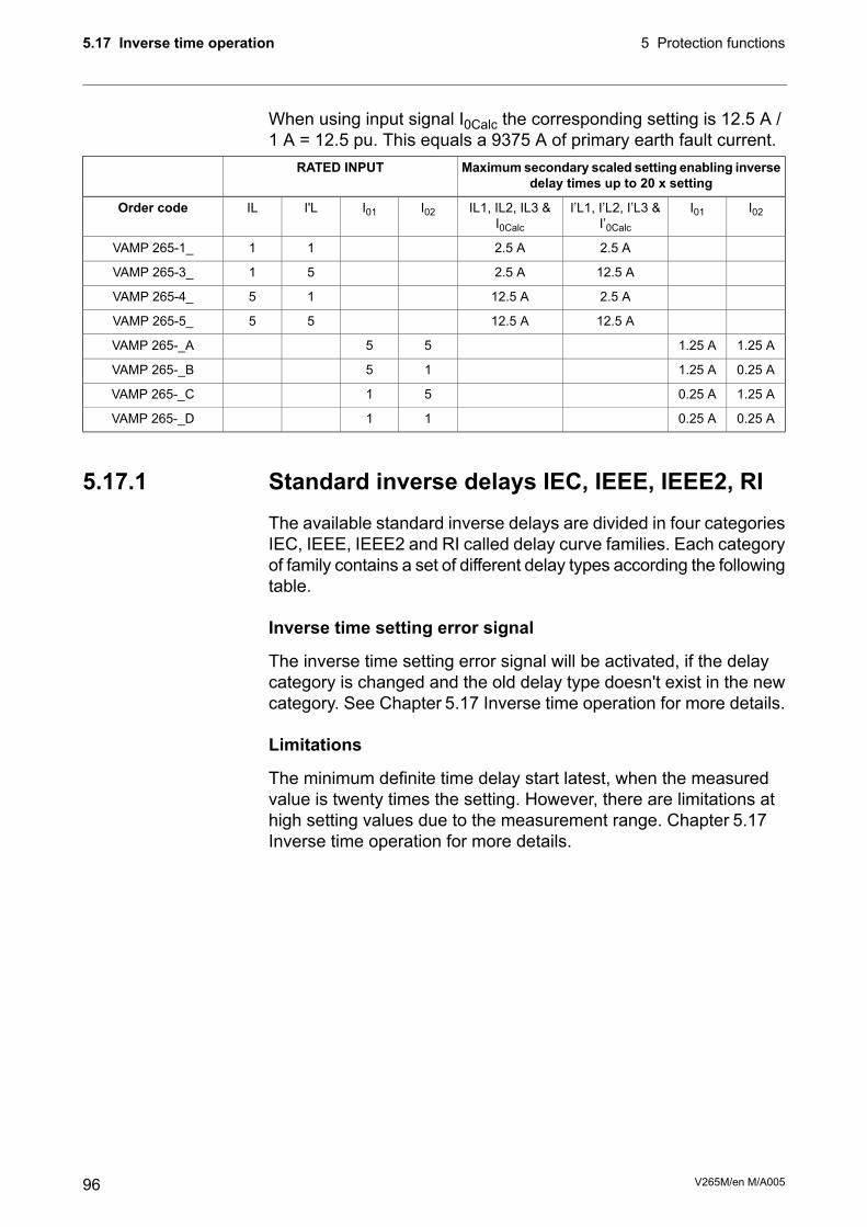
When using input signal I0Calc the corresponding setting is 12.5 A /1 A = 12.5 pu. This equals a 9375 A of primary earth fault current.
Maximumsecondary scaled setting enabling inversedelay times up to 20 x setting
RATED INPUT
I02I01I’L1, I’L2, I’L3 &I’0Calc
IL1, IL2, IL3 &I0Calc
I02I01I'LILOrder code
2.5 A2.5 A11VAMP 265-1_
12.5 A2.5 A51VAMP 265-3_
2.5 A12.5 A15VAMP 265-4_
12.5 A12.5 A55VAMP 265-5_
1.25 A1.25 A55VAMP 265-_A
0.25 A1.25 A15VAMP 265-_B
1.25 A0.25 A51VAMP 265-_C
0.25 A0.25 A11VAMP 265-_D
5.17.1 Standard inverse delays IEC, IEEE, IEEE2, RIThe available standard inverse delays are divided in four categoriesIEC, IEEE, IEEE2 and RI called delay curve families. Each categoryof family contains a set of different delay types according the followingtable.
Inverse time setting error signal
The inverse time setting error signal will be activated, if the delaycategory is changed and the old delay type doesn't exist in the newcategory. See Chapter 5.17 Inverse time operation for more details.
Limitations
The minimum definite time delay start latest, when the measuredvalue is twenty times the setting. However, there are limitations athigh setting values due to the measurement range. Chapter 5.17Inverse time operation for more details.
V265M/en M/A00596
5 Protection functions5.17 Inverse time operation

Table 5.27: Available standard delay families and the available delay typeswithin each family.
Curve familyDelay type
RIIEEE2IEEEIECDT
XDefinite timeDT
XXNormal inverseNI
XXXVery inverseVI
XXXExtremely inverseEI
XXLong time inverseLTI
XLong time extremely inverseLTEI
XLong time very inverseLTVI
XXModerately inverseMI
XShort time inverseSTI
XShort time extremely inverseSTEI
XOld ASEA typeRI
XOld ASEA typeRXIDG
IEC inverse time operation
The operation time depends on the measured value and otherparameters according Equation 5.3. Actually this equation can onlybe used to draw graphs or when the measured value I is constantduring the fault. A modified version is implemented in the relay forreal time usage.
t = Operation delay in secondsEquation 5.3:
1−
=B
PICKUPI
I
Akt
k = User’s multiplier
I = Measured value
IPICKUP = User’s pick up setting
A, B = Constants parameters according Table 5.28.
There are three different delay types according IEC 60255-3, Normalinverse (NI), Extremely inverse (EI), Very inverse (VI) and a VIextension. Additional there is a de facto standard Long time inverse(LTI).Table 5.28: Constants for IEC inverse delay equation
ParameterDelay type
BA
0.020.14Normal inverseNI
280Extremely inverseEI
113.5Very inverseVI
1120Long time inverseLTI
97V265M/en M/A005
5.17 Inverse time operation5 Protection functions

Example for Delay type "Normal inverse (NI)":
k = 0.50
I = 4 pu (constant current)
IPICKUP = 2 pu
A = 0.14
B = 0.02
0.5
12
4
14.050.0
02.0=
−
⋅=t
The operation time in this example will be 5 seconds. The sameresult can be read from Figure 5.29.
Figure 5.30: IEC extremely inverse delay.Figure 5.29: IEC normal inverse delay.
V265M/en M/A00598
5 Protection functions5.17 Inverse time operation

Figure 5.32: IEC long time inverse delay.Figure 5.31: IEC very inverse delay.
IEEE/ANSI inverse time operation
There are three different delay types according IEEE StdC37.112-1996 (MI, VI, EI) and many de facto versions accordingTable 5.29. The IEEE standard defines inverse delay for both tripand release operations. However, in the VAMP relay only the triptime is inverse according the standard but the release time isconstant.
The operation delay depends on the measured value and otherparameters according Equation 5.4. Actually this equation can onlybe used to draw graphs or when the measured value I is constantduring the fault. A modified version is implemented in the relay forreal time usage.
t = Operation delay in secondsEquation 5.4:
+
−
= B
I
I
Akt
C
PICKUP
1
k = User’s multiplier
I = Measured value
IPICKUP = User’s pick up setting
A,B,C = Constant parameter according Table 5.29.
99V265M/en M/A005
5.17 Inverse time operation5 Protection functions

Table 5.29: Constants for IEEE/ANSI inverse delay equationParameterDelay type
CBA
0.020.1850.086Long time inverseLTI
20.71228.55Long time very inverseLTVI
20.25064.07Long time extremely inverseLTEI
0.020.11400.0515Moderately inverseMI
20.49119.61Very inverseVI
20.121728.2Extremely inverseEI
0.020.118580.16758Short time inverseSTI
20.0051.281Short time extremely inverseSTEI
Example for Delay type "Moderately inverse (MI)":
k = 0.50
I = 4 pu
IPICKUP = 2 pu
A = 0.0515
B = 0.114
C = 0.02
9.11140.0
12
4
0515.050.0
02.0=
+
−
⋅=t
The operation time in this example will be 1.9 seconds. The sameresult can be read from Figure 5.36.
V265M/en M/A005100
5 Protection functions5.17 Inverse time operation

Figure 5.34: ANSI/IEEE long time very inverse delayFigure 5.33: ANSI/IEEE long time inverse delay
Figure 5.36: ANSI/IEEE moderately inverse delayFigure 5.35: ANSI/IEEE long time extremely inversedelay
101V265M/en M/A005
5.17 Inverse time operation5 Protection functions

Figure 5.38: ANSI/IEEE short time extremely inversedelay
Figure 5.37: ANSI/IEEE short time inverse delay
IEEE2 inverse time operation
Before the year 1996 and ANSI standard C37.112 microprocessorrelays were using equations approximating the behaviour of variousinduction disc type relays. A quite popular approximation isEquation 5.5, which in VAMP relays is called IEEE2. Another namecould be IAC, because the old General Electric IAC relays have beenmodeled using the same equation.
There are four different delay types according Table 5.30. The oldelectromechanical induction disc relays have inverse delay for bothtrip and release operations. However, in VAMP relays only the triptime is inverse the release time being constant.
The operation delay depends on the measured value and otherparameters according Equation 5.5. Actually this equation can onlybe used to draw graphs or when the measured value I is constantduring the fault. A modified version is implemented in the relay forreal time usage.
V265M/en M/A005102
5 Protection functions5.17 Inverse time operation

Equation 5.5:
−
+
−
+
−
+=32
CI
I
E
CI
I
D
CI
I
BAkt
PICKUPPICKUPPICKUP
t = Operation delay in seconds
k = User’s multiplier
I = Measured value
IPICKUP = User’s pick up setting
A, B, C, D = Constant parameter according Table 5.30.Table 5.30: Constants for IEEE2 inverse delay equation
ParameterDelay type
EDCBA
0.1271-0.080.80.67910.1735Moderately inverseMI
9.1272-0.18990.32.26140.0274Normally inverseNI
4.0505-0.2840.340.79890.0615Very inverseVI
0.72223.00940.50.22940.0399Extremely inverseEI
Example for Delay type "Moderately inverse (MI)":
k = 0.50
I = 4 pu
IPICKUP = 2 pu
A = 0.1735
B = 0.6791
C = 0.8
D = -0.08
E = 0.127
38.0
8.02
4
127.0
8.02
4
08.0
8.02
4
6791.01735.05.0
32=
−
+
−
−+
−
+⋅=t
The operation time in this example will be 0.38 seconds. The sameresult can be read from Figure 5.39.
103V265M/en M/A005
5.17 Inverse time operation5 Protection functions

Figure 5.40: IEEE2 normal inverse delayFigure 5.39: IEEE2 moderately inverse delay
Figure 5.42: IEEE2 extremely inverse delayFigure 5.41: IEEE2 very inverse delay
V265M/en M/A005104
5 Protection functions5.17 Inverse time operation

RI and RXIDG type inverse time operation
These two inverse delay types have their origin in old ASEA(nowadays ABB) earth fault relays.
The operation delay of types RI and RXIDG depends on themeasured value and other parameters according Equation 5.6 andEquation 5.7. Actually these equations can only be used to drawgraphs or when the measured value I is constant during the fault.Modified versions are implemented in the relay for real time usage.
Equation 5.7: RXIDG
PICKUP
RXIDG
Ik
It ln35.18.5 −=
Equation 5.6: RI
−
=
PICKUP
RI
I
I
kt
236.0339.0
t = Operation delay in seconds
k = User’s multiplier
I = Measured value
IPICKUP = User’s pick up setting
Example for Delay type RI
k = 0.50
I = 4 pu
IPICKUP = 2 pu
3.2
2
4
236.0339.0
5.0=
−
=RIt
The operation time in this example will be 2.3 seconds. The sameresult can be read from Equation 5.6.
Example for Delay type RXIDG
k = 0.50
I = 4 pu
IPICKUP = 2 pu
9.325.0
4ln35.18.5 =
⋅−=
RXIDGt
105V265M/en M/A005
5.17 Inverse time operation5 Protection functions

The operation time in this example will be 3.9 seconds. The sameresult can be read from Figure 5.44.
Figure 5.44: Inverse delay of type RXIDG.Figure 5.43: Inverse delay of type RI.
V265M/en M/A005106
5 Protection functions5.17 Inverse time operation

5.17.2 Free parameterization using IEC, IEEE andIEEE2 equationsThis mode is activated by setting delay type to ‘Parameters’, andthen editing the delay function constants, i.e. the parameters A – E.The idea is to use the standard equations with one’s own constantsinstead of the standardized constants as in the previous chapter.
Example for GE-IAC51 delay type inverse:
k = 0.50
I = 4 pu
IPICKUP = 2 pu
A = 0.2078
B = 0.8630
C = 0.8000
D = - 0.4180
E = 0.1947
37.0
8.02
4
1947.0
8.02
4
4180.0
8.02
4
8630.02078.05.0
32=
−
+
−
−+
−
+⋅=t
The operation time in this example will be 0.37 seconds.
The resulting time/current characteristic of this example matchesquite well with the characteristic of the old electromechanical IAC51induction disc relay.
Inverse time setting error signal
The inverse time setting error signal will become active, ifinterpolation with the given parameters is not possible. SeeChapter 5.17 Inverse time operation for more details.
Limitations
The minimum definite time delay start latest, when the measuredvalue is twenty times the setting. However, there are limitations athigh setting values due to the measurement range. See Chapter5.17Inverse time operation for more details.
107V265M/en M/A005
5.17 Inverse time operation5 Protection functions

5.17.3 Programmable inverse time curvesOnly with VAMPSET, requires rebooting.
The [current, time] curve points are programmed using VAMPSETPC program. There are some rules for defining the curve points:
• configuration must begin from the topmost line
• line order must be as follows: the smallest current (longestoperation time) on the top and the largest current (shortestoperation time) on the bottom
• all unused lines (on the bottom) should be filled with [1.00 0.00s]
Here is an example configuration of curve points:Operation delayCurrent I/IPICKUPPoint
10.00 s1.001
6.50 s2.002
4.00 s5.003
3.00 s10.004
2.00 s20.005
1.00 s40.006
0.00 s1.007
0.00 s1.008
0.00 s1.009
0.00 s1.0010
0.00 s1.0011
0.00 s1.0012
0.00 s1.0013
0.00 s1.0014
0.00 s1.0015
0.00 s1.0016
Inverse time setting error signal
The inverse time setting error signal will be activated, if interpolationwith the given points fails. See Chapter 5.17 Inverse time operationfor more details.
Limitations
The minimum definite time delay start latest, when the measuredvalue is twenty times the setting. However, there are limitations athigh setting values due to the measurement range. See Chapter5.17Inverse time operation for more details.
V265M/en M/A005108
5 Protection functions5.17 Inverse time operation

6 Supporting functions
6.1 Event logEvent log is a buffer of event codes and time stamps including dateand time. For example each start-on, start-off, trip-on or trip-off ofany protection stage has a unique event number code. Such a codeand the corresponding time stamp is called an event.
Communicationprotocols
Local panelDescriptionEVENT
YesYesChannel 30, event 2Code: 30E2
NoYesEvent textU> trip on
NoYesFault value1.2 x Imot
YesYesDate2007-01-31
YesYesTime08:35:13.413
NoYesFault typeType: U12, 23, 31
Events are the major data for a SCADA system. SCADA systemsare reading events using any of the available communicationprotocols. Event log can also be scanned using the front panel orusing VAMPSET. With VAMPSET the events can be stored to a fileespecially in case the relay is not connected to any SCADA system.
Only the latest event can be read when using communicationprotocols or VAMPSET. Every reading increments the internal readpointer to the event buffer. (In case of communication interruptions,the latest event can be reread any number of times using anotherparameter.) On the local panel scanning the event buffer back andforth is possible.
Event enabling/masking
In case of an uninteresting event, it can be masked, which preventsthe particular event(s) to be written in the event buffer. As a defaultthere is room for 200 latest events in the buffer. Event buffer sizecan be modified from 50 to 2000.
Modification can be done in “Local panel conf” –menu.
Indication screen (popup screen) can also be enabled in this samemenu when VAMPSET –setting tool is used. The oldest one will beoverwritten, when a new event does occur. The shown resolution ofa time stamp is one millisecond, but the actual resolution dependsof the particular function creating the event. For example mostprotection stages create events with 5ms, 10 ms or 20 ms resolution.The absolute accuracy of all time stamps depends on the timesynchronizing of the relay. See Chapter 6.5 System clock andsynchronization for system clock synchronizing.
109V265M/en M/A005
6 Supporting functions

Event buffer overflow
The normal procedure is to poll events from the device all the time.If this is not done then the event buffer could reach its limits. In suchcase the oldest event is deleted and the newest displayed with OVFcode in HMI.Table 6.1: Setting parameters for events
NoteDescriptionValueParameter
Number of eventsCount
SetClear event buffer-
Clear
ClrEn
SetOrder of the event buffer for local displayOld-New
New-Old
Order
SetScaling of event fault valueFVSca
Per unit scalingPU
Primary scalingPri
SetIndication dispaly is enabled
No indication display
On
Off
Display
Alarms
FORMAT OF EVENTS ON THE LOCAL DISPLAY
CH = event channel, NN=event codeCode: CHENN
Event channel and code in plain textEvent description
Date
(for available date formats, see Chapter 6.5 System clock and synchronization)
yyyy-mm-dd
Timehh:mm:ss.nnn
V265M/en M/A005110
6 Supporting functions6.1 Event log

6.2 Disturbance recorderThe disturbance recorder can be used to record all the measuredsignals, that is, currents, voltage and the status information of digitalinputs (DI) and digital outputs (DO).
The digital inputs include also the arc protection signals S1, S2, BIand BO, if the optional arc protection is available.
Triggering the recorder
The recorder can be triggered by any start or trip signal from anyprotection stage or by a digital input. The triggering signal is selectedin the output matrix (vertical signal DR). The recording can also betriggered manually. All recordings are time stamped.
Reading recordings
The recordings can be uploaded, viewed and analysed with theVAMPSET program. The recording is in COMTRADE format. Thisalso means that other programs can be used to view and analysethe recordings made by the relay.
For more details, please see a separate VAMPSET manual.
Number of channels
At the maximum, there can be 12 recordings, and the maximumselection of channels in one recording 12 (limited in wave form) anddigital inputs reserve one channel (includes all the inputs). Also thedigital outputs reserve one channel (includes all the outputs). If digitalinputs and outputs are recorded, there will be still 10 channels leftfor analogue waveforms.
111V265M/en M/A005
6.2 Disturbance recorder6 Supporting functions

Table 6.2: VAMP 265M Distrubance recorder waveformAvailable for waveformDescriptionChannel
YesPhase currentIL1, IL2, IL3
YesPhase currentI’L1, I’L2, I’L3
YesMeasured residual currentIo1, Io2
-Frequencyf
-Phasor sum Io = (IL1 + IL2 + IL3) / 3IoCalc
-Phasor sum Io = (I’L1 + I’L2 + I’L3) / 3I’oCalc
-Positive sequence currentI1, I’1
-Negative sequence currentI2, I’2
-Relative current unbalanceI2/I1, I’2/I’1
-Current unbalance [x IN]I2/In, I’2/I’n
-Average (IL1 + IL2 + IL3) / 3IL
-Average (I’L1 + I’L2 + I’L3) / 3I’L
YesDigital outputsDO
YesDigital inputsDI
-Total harmonic distortion of IL1THDIL1
-Total harmonic distortion of I’L1THDI’L1
-Total harmonic distortion of IL2THDIL2
-Total harmonic distortion of I’L2THDI’L2
-Total harmonic distortion of IL3THDIL3
-Total harmonic distortion of I’L3THDI’L3
-IL1 RMS for average samplingIL1RMS
-IL2 RMS for average samplingIL2RMS
-IL3 RMS for average samplingIL3RMS
ILmin
I’Lmin
ILmax
I’Lmax
ΔIL1,ΔIL2,ΔIL3
IL1w,IL2w,IL3w
I’L1w,I’L2w,I’L3w
V265M/en M/A005112
6 Supporting functions6.2 Disturbance recorder

Table 6.3: Disturbance recorder parametersNoteDescriptionUnitValueParameter
SetBehavior in memory full situation:Mode
No more recordings are acceptedSaturated
The oldest recorder will be overwrittenOverflow
SetSample rateSR
Waveform32/cycle
Waveform16/cycle
Waveform8/cycle
One cycle value *)1/10ms
One cycle value **)1/20ms
Average1/200 ms
Average1/1s
Average1/5s
Average1/10s
Average1/15s
Average1/30s
Average1/1min
SetRecording lengthsTime
SetAmount of recording data before the trig moment%PreTrig
Maximum time setting.sMaxLen
This value depends on sample rate, number and type of the se-lected channels and the configured recording length.
Status of recordingStatus
Not active-
Waiting a triggeringRun
RecordingTrig
Memory is full in saturated modeFULL
SetManual triggering-, TrigManTrig
n = Available recordings / m = maximum number of recordingsn/mReadyRec
The value of 'm' depends on sample rate, number and type ofthe selected channels and the configured recording length.
113V265M/en M/A005
6.2 Disturbance recorder6 Supporting functions

NoteDescriptionUnitValueParameter
SetAdd one channel. Maximum simultaneous number of channelsis 12.
AddCh
Phase currentIL1, IL2, IL3
Phase current (lV side)I’L1, I’L2, I’L3
Measured residual currentIo1, Io2
Frequencyf
Phasor sum Io = (IL1+IL2+IL3)/3 (HV side)IoCalc
Positive sequence current (HV side)I1
Negative sequence current (HV side)I2
Relative current unbalance (HV side)I2/I1
Current unbalance [x IMOT]I2/Imot
Current unbalance [x IN] (HV side)
Positive sequence current (LV side)I’1
Negative sequence current (LV side)I’2
Relative current unbalance (LV side)I’2/I’1
Current unbalance [x I'N] (LV side)I’2/I’n
Phasor sum Io = (I'L1+I'L2+I'L3)/3 (LV side)I’oCalc
Average (IL1 + IL2 + IL3) / 3IL
Average (I'L1 + I'L2 + I'L3) / 3I’L
Digital inputs, Digital outputsDI, DO
Total harmonic distortion of IL1, IL2 or IL3THDIL1, THDIL2,THDIL3
IL1, IL2, IL3 RMS for average samplingIL1RMS, IL2MRS,IL3RMS
Min and max of phase currentsILmin, ILmax
Min and max of phase currents (LV side)I’Lmin, I’Lmax
Differential currentΔIL1, ΔIL2, ΔIL3
Winding current (HV side)IL1w, IL2w, IL3w
Winding current (LV side)I’L1w, I’L2w, I’L3w
Protection stage start signalsStarts
Protection stage trip signalsTrips
Delete selected channelDelete recorderchannel
SetRemove all channels-, ClearClrCh
List of selected channels(Ch)
Set = An editable parameter (password needed).
*) This is the fundamental frequency rms value of one cycle updated every 10 ms.
**) This is the fundamental frequency rms value of one cycle updated every 20 ms.
For details of setting ranges, see Chapter 12.4 Supporting functions
V265M/en M/A005114
6 Supporting functions6.2 Disturbance recorder

6.2.1 Running virtual comtrade filesVirtual comtrade files can be run with VAMP relays with the v.10.74software or a later version. Relay behaviour can be analysed byplaying the recorder data over and over again in the relay memory.
Steps of opening the VAMPSET setting tool:
1. Go to “Disturbance record” and select Open… (A).
2. Select the comtrade file from you hard disc or equivalent.VAMPSET is now ready to read the recording.
3. The virtual measurement has to be enabled (B) in order to sendrecord data to the relay (C).
4. Sending the file to the device’s memory takes a few seconds.Initiate playback of the file by pressing the Go! button (D). The“Change to control mode” button takes you back to the virtualmeasurement.
NOTE: The sample rate of the comtrade file has to be 32/cycle (625 microseconds when 50 Hz is used). The channel names have tocorrespond to the channel names in VAMP relays: IL1, IL2, IL3, I01,I02, U12, U23, UL1, UL2, UL3 and U0.
115V265M/en M/A005
6.2 Disturbance recorder6 Supporting functions

6.3 Current transformer supervisionThe relay supervise the external wiring between the relay terminalsand current transformers (CT) and the CT themselves. Furthermore,this is a safety function as well, since an open secondary of a CT,causes dangerous voltages.
The CT supervisor function measures phase currents. If one of thethree phase currents drops below IMIN< setting, while another phasecurrent is exceeding the IMAX> setting, the function will issue an alarmafter the operation delay has elapsed.Table 6.4: Setting parameters of CT, CT’ supervisor CTSV
DescriptionDefaultUnitValueParameter
Upper setting for CT supervisor currentscaled to primary value, calculated by relay
2.0xImot0.0 – 10.0Imax>
Lower setting for CT supervisor currentscaled to primary value, calculated by relay
0.2xImot0.0 – 10.0Imin<
Operation delay0.10s0.02 – 600.0t>
CT supervisor on eventOn-On; OffCT on
CT supervisor off eventOn-On; OffCT off
Table 6.5: Measured and recorded values of CT, CT’ supervisor CTSVDescriptionUnitValueParameter
Maximum of phase currentsAILmaxMeasured value
Minimum of phase currentsAILmin
Setting values as primary valuesAImax>, Imin<Display
Date of CT supervision alarm-DateRecorded values
Time of CT supervision alarm-Time
Maximum phase currentAImax
Minimum phase currentAImin
For details of setting ranges, see Chapter 12.4 Supporting functions
V265M/en M/A005116
6 Supporting functions6.3 Current transformer supervision

6.4 Circuit breaker condition monitoringThe relay has a condition monitoring function that supervises thewearing of the circuit-breaker. The condition monitoring can givealarm for the need of CB maintenance well before the CB conditionis critical.
The CB wear function measures the breaking current of each CBpole separately and then estimates the wearing of the CB accordinglythe permissible cycle diagram. The breaking current is registeredwhen the trip relay supervised by the circuit breaker failure protection(CBFP) is activated. (See Chapter 5.14 Circuit breaker failureprotection CBFP (50BF) for CBFP and the setting parameter"CBrelay".)
Breaker curve and its approximation
The permissible cycle diagram is usually available in thedocumentation of the CB manufacturer (Figure 6.1). The diagramspecifies the permissible number of cycles for every level of thebreaking current. This diagram is parameterised to the conditionmonitoring function with maximum eight [current, cycles] points. SeeTable 6.6. If less than eight points needed, the unused points areset to [IBIG, 1], where IBIG is more than the maximum breakingcapacity.
If the CB wearing characteristics or part of it is a straight line on alog/log graph, the two end points are enough to define that part ofthe characteristics. This is because the relay is using logarithmicinterpolation for any current values falling in between the givencurrent points 2 – 8.
The points 4 – 8 are not needed for the CB in Figure 6.1. Thus theyare set to 100 kA and one operation in the table to be discarded bythe algorithm.
10
20
50
100
1000
10000
100000
100 200 500 1000 10000 100000
Num
ber
of perm
itte
d o
pera
tions
Breaked current (A) CBWEARcharacteristics
Figure 6.1: An example of a circuit breaker wearing characteristic graph.
117V265M/en M/A005
6.4 Circuit breaker condition monitoring6 Supporting functions

Table 6.6: An example of circuit breaker wearing characteristics in a tableformat. The values are taken from the figure above. The table is edited withVAMPSET under menu "BREAKER CURVE".
Number of permitted
operations
Interrupted current
(kA)
Point
100000 (mechanical age)1
100001.25 (rated current)2
8031.0 (maximum breaking current)3
11004
11005
11006
11007
11008
Setting alarm points
There are two alarm points available having two setting parameterseach.
• CurrentThe first alarm can be set for example to nominal current of theCB or any application typical current. The second alarm can beset for example according a typical fault current.
• Operations left alarm limitAn alarm is activated when there are less operation left at thegiven current level than this limit.
Any actual interrupted current will be logarithmically weighted for thetwo given alarm current levels and the number of operations left atthe alarm points is decreased accordingly. When the "operationsleft" i.e. the number of remaining operations, goes under the givenalarm limit, an alarm signal is issued to the output matrix. Also anevent is generated depending on the event enabling.
Clearing "operations left" counters
After the breaker curve table is filled and the alarm currents aredefined, the wearing function can be initialised by clearing thedecreasing operation counters with parameter "Clear" (Clear oper.left cntrs). After clearing the relay will show the maximum allowedoperations for the defined alarm current levels.
Operation counters to monitor the wearing
The operations left can be read from the counters "Al1Ln" (Alarm 1)and "Al2Ln" (Alarm2). There are three values for both alarms, onefor each phase. The smallest of three is supervised by the two alarmfunctions.
V265M/en M/A005118
6 Supporting functions6.4 Circuit breaker condition monitoring
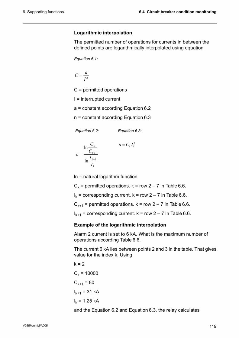
Logarithmic interpolation
The permitted number of operations for currents in between thedefined points are logarithmically interpolated using equation
Equation 6.1:
nI
aC =
C = permitted operations
I = interrupted current
a = constant according Equation 6.2
n = constant according Equation 6.3
Equation 6.3:
2
kkICa =
Equation 6.2:
k
k
k
k
I
I
C
C
n
1
1
ln
ln
+
+=
ln = natural logarithm function
Ck = permitted operations. k = row 2 – 7 in Table 6.6.
Ik = corresponding current. k = row 2 – 7 in Table 6.6.
Ck+1 = permitted operations. k = row 2 – 7 in Table 6.6.
Ik+1 = corresponding current. k = row 2 – 7 in Table 6.6.
Example of the logarithmic interpolation
Alarm 2 current is set to 6 kA. What is the maximum number ofoperations according Table 6.6.
The current 6 kA lies between points 2 and 3 in the table. That givesvalue for the index k. Using
k = 2
Ck = 10000
Ck+1 = 80
Ik+1 = 31 kA
Ik = 1.25 kA
and the Equation 6.2 and Equation 6.3, the relay calculates
119V265M/en M/A005
6.4 Circuit breaker condition monitoring6 Supporting functions

5038.1
1250
31000ln
80
10000ln
==n
65038.110454125010000 ⋅=⋅=a
Using Equation6.1 the relay gets the number of permitted operationsfor current 6 kA.
9456000
10454
5038.1
6
=⋅
=C
Thus the maximum number of current breaking at 6 kA is 945. Thiscan be verified with the original breaker curve in Figure 6.1. Indeed,the figure shows that at 6 kA the operation count is between 900and 1000. A useful alarm level for operation-left, could be in thiscase for example 50 being about five per cent of the maximum.
Example of operation counter decrementing when the CB isbreaking a current
Alarm2 is set to 6 kA. CBFP is supervising trip relay T1 and trip signalof an overcurrent stage detecting a two phase fault is connected tothis trip relay T1. The interrupted phase currents are 12.5 kA, 12.5kA and 1.5 kA. How many are Alarm2 counters decremented?
Using Equation 6.1 and values n and a from the previous example,the relay gets the number of permitted operation at 10 kA.
31312500
10454
5038.1
6
10=
⋅=
kAC
At alarm level 2, 6 kA, the corresponding number of operations iscalculated according
Equation 6.4:
C
CAlarmMax
=∆
3
313
945
21==∆=∆
LL
Thus Alarm2 counters for phases L1 and L2 are decremented by 3.In phase L1 the currents is less than the alarm limit current 6 kA. Forsuch currents the decrement is one.
ΔL3 = 1
V265M/en M/A005120
6 Supporting functions6.4 Circuit breaker condition monitoring

Table 6.7: Local panel parameters of CBWEAR functionSetDescriptionUnitValueParameter
CBWEAR STATUS
Operations left for
- Alarm 1, phase L1
- Alarm 1, phase L2
- Alarm 1, phase L3
- Alarm 2, phase L1
- Alarm 2, phase L2
- Alarm 2, phase L3
-
Al1L1
Al1L2
Al1L3
Al2L1
Al2L2
Al2L3
Latest trip
Time stamp of the latest trip operationDate
time
Broken current of phase L1
Broken current of phase L2
Broken current of phase L3
A
A
A
IL1
IL2
IL3
CBWEAR SET
Alarm1
SetAlarm1 current levelkA0.00 – 100.00Current
SetAlarm1 limit for operations left100000 – 1Cycles
Alarm2
SetAlarm2 current levelkA0.00 – 100.00Current
SetAlarm2 limit for operations left100000 – 1Cycles
CBWEAR SET2
Set'Alarm1 on' event enablingOn
Off
Al1On
Set'Alarm1 off' event enablingOn
Off
Al1Off
Set'Alarm2 on' event enablingOn
Off
Al2On
Set'Alarm2 off' event enablingOn
Off
Al2Off
SetClearing of cycle counters-
Clear
Clear
Set = An editable parameter (password needed).
The breaker curve table is edited with VAMPSET.
121V265M/en M/A005
6.4 Circuit breaker condition monitoring6 Supporting functions

6.5 System clock and synchronizationThe internal clock of the relay is used to time stamp events anddisturbance recordings.
The system clock should be externally synchronised to getcomparable event time stamps for all the relays in the system.
The synchronizing is based on the difference of the internal time andthe synchronising message or pulse. This deviation is filtered andthe internal time is corrected softly towards a zero deviation.
Time zone offsets
Time zone offset (or bias) can be provided to adjust the local timefor IED. The Offset can be set as a Positive (+) or Negative (-) valuewithin a range of -15.00 to +15.00 hours and a resolution of 0.01/h.Basically quarter hour resolution is enough.
Daylight saving time (DST)
IED provides automatic daylight saving adjustments when configured.A daylight savings time (summer time) adjustment can be configuredseparately and in addition to a time zone offset.
Daylight time standards vary widely throughout the world. Traditionaldaylight/summer time is configured as one (1) hour positive bias.The new US/Canada DST standard, adopted in the spring of 2007is: one (1) hour positive bias, starting at 2:00am on the secondSunday in March, and ending at 2:00am on the first Sunday inNovember. In the European Union, daylight change times are definedrelative to the UTC time of day instead of local time of day (as inU.S.) European customers, please carefully find out local countryrules for DST.
V265M/en M/A005122
6 Supporting functions6.5 System clock and synchronization

The daylight saving rules for Finland are the IED defaults (24-hourclock):
- Daylight saving time start: Last Sunday of March at 03.00
- Daylight saving time end: Last Sunday of October at 04.00
To ensure proper hands-free year-around operation, automaticdaylight time adjustments must be configured using the “EnableDST” and not with the time zone offset option.
Adapting auto adjust
During tens of hours of synchronizing the device will learn its averagedeviation and starts to make small corrections by itself. The targetis that when the next synchronizing message is received, thedeviation is already near zero. Parameters "AAIntv" and "AvDrft" willshow the adapted correction time interval of this ±1 ms auto-adjustfunction.
Time drift correction without external sync
If any external synchronizing source is not available and the systemclock has a known steady drift, it is possible to roughly correct theclock deviation by editing the parameters "AAIntv" and "AvDrft". Thefollowing equation can be used if the previous "AAIntv" value hasbeen zero.
WeekDriftInOneAAIntv
8.604=
If the auto-adjust interval "AAIntv" has not been zero, but furthertrimming is still needed, the following equation can be used tocalculate a new auto-adjust interval.
8.604
1
1
WeekDriftInOne
AAIntv
AAIntv
PREVIOUS
NEW
+
=
The term DriftInOneWeek/604.8 may be replaced with the relativedrift multiplied by 1000, if some other period than one week has been
123V265M/en M/A005
6.5 System clock and synchronization6 Supporting functions

used. For example if the drift has been 37 seconds in 14 days, therelative drift is 37*1000/(14*24*3600) = 0.0306 ms/s.
Example 1
If there has been no external sync and the relay's clock is leadingsixty-one seconds a week and the parameter AAIntv has been zero,the parameters are set as
sAAIntv
LeadAvDrft
9.961
8.604==
=
With these parameter values the system clock corrects itself with –1ms every 9.9 seconds which equals –61.091 s/week.
Example 2
If there is no external sync and the relay's clock has been laggingfive seconds in nine days and the AAIntv has been 9.9 s, leading,then the parameters are set as
6.10
3600249
5000
9.9
1
1=
⋅⋅
−
=NEW
AAIntv
LeadAvDrft =
When the internal time is roughly correct – deviation is less than fourseconds – any synchronizing or auto-adjust will never turn the clockbackwards. Instead, in case the clock is leading, it is softly sloweddown to maintain causality.
V265M/en M/A005124
6 Supporting functions6.5 System clock and synchronization

Table 6.8: System clock parametersNoteDescriptionUnitValueParameter
SetCurrent dateDate
SetCurrent timeTime
SetDate formatStyle
Year-Month-Dayy-d-m
Day.Month.Yeard.m.y
Month/Day/Yearm/d/y***)DI not used for synchronizing-SyncDI
Minute pulse inputDI1 – DI6
SetUTC time zone for SNTP synchronization.
Note: This is a decimal number. For example for stateof Nepal the time zone 5:45 is given as 5.75
-15.00 – +15.00 *)TZone
SetDaylight saving time for SNTPNo; YesDST
Clock synchronisation sourceSySrc
No sync recognized since 200sInternal
Digital inputDI
Protocol syncSNTP
Protocol syncSpaBus
Protocol syncModBus
Protocol syncModBus TCP
Protocol syncProfibusDP
Protocol syncIEC101
Protocol syncIEC103
Protocol syncDNP3
IRIG timecode B003 ****)IRIG-B003
The number of received synchronisation messages orpulses
0 – 65535,
0 – etc.
MsgCnt
Latest time deviation between the system clock andthe received synchronization
ms±32767Dev
SetSynchronisation correction for any constant deviationin the synchronizing source.
s±10000.000SyOS
Set**)Adapted auto adjust interval for 1 ms corrections±10000AAIntv
Set**)Adapted average clock drift signLead; LagAvDrft
Filtered synchronisation deviationms±125FilDev
Set = An editable parameter (password needed).
*) A range of -11 h – +12 h would cover the whole Earth but because the International Date Line does not follow the 180°meridian, a more wide range is needed.
**) If external synchronization is used this parameter will be set automatically.
***) Set the DI delay to its minimum and the polarity such that the leading edge is the synchronizing edge.
****) Relay needs to be equipped with suitable hardware option module to receive IRIG-B clock synchronization signal.(Chapter 14 Order information).
125V265M/en M/A005
6.5 System clock and synchronization6 Supporting functions

Synchronisation with DI
Clock can be synchronized by reading minute pulses from digitalinputs, virtual inputs or virtual outputs. Sync source is selected withSyncDI setting. When rising edge is detected from the selected input,system clock is adjusted to the nearest minute. Length of digital inputpulse should be at least 50 ms. Delay of the selected digital inputshould be set to zero.
Synchronisation correction
If the sync source has a known offset delay, it can be compensatedwith SyOS setting. This is useful for compensating hardware delaysor transfer delays of communication protocols. A positive value willcompensate a lagging external sync and communication delays. Anegative value will compensate any leading offset of the externalsynch source.
Sync source
When the device receives new sync message, the sync sourcedisplay is updated. If no new sync messages are received withinnext 1.5 minutes, the device will change to internal sync mode.
Sync source: IRIG-B003
IRIG-B003 synchronization is supported with a dedicatedcommunication option with either a two-pole or two pins in a D9 rearconnector (See Chapter 14 Order information).
IRIG-B003 input clock signal voltage level is TLL. The input clocksignal originated in the GPS receiver must be taken to multiple relaystrough an IRIG-B distribution module. This module acts as acentralized unit for a point-to-multiple point connection. Note: Daisychain connection of IRIG-B signal inputs in multiple relays must beavoided.
V265M/en M/A005126
6 Supporting functions6.5 System clock and synchronization

IRIG-B
Distribution
Module
GPS-Clock
Antenna
IRIG-B signal
from clock
Recommended wiring: shielded cable of twisted-pair or coaxial type with a maximum length of 10 meters.
VAMP50 VAMP300 VAMP200
VAMP Relay Series with IRIG-B synchronization capability
VAMP 321 Arc Flash Protection System
The recommended cable must be shielded and either of coaxial ortwisted pair type. Its length should not exceed a maximum of 10meters.
Deviation
The time deviation means how much system clock time differs fromsync source time. Time deviation is calculated after receiving newsync message. The filtered deviation means how much the systemclock was really adjusted. Filtering takes care of small deviation insync messages.
Auto-lag/lead
The device synchronizes to the sync source, meaning it startsautomatically leading or lagging to stay in perfect sync with themaster. The learning process takes few days.
127V265M/en M/A005
6.5 System clock and synchronization6 Supporting functions
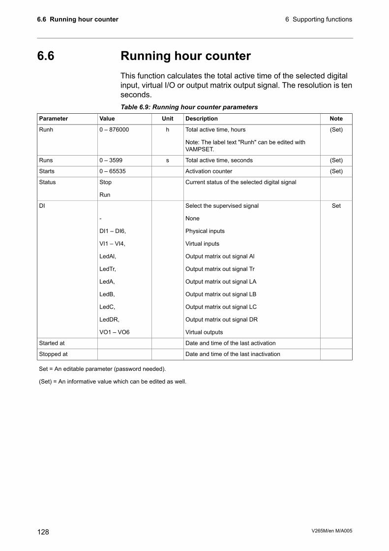
6.6 Running hour counterThis function calculates the total active time of the selected digitalinput, virtual I/O or output matrix output signal. The resolution is tenseconds.Table 6.9: Running hour counter parameters
NoteDescriptionUnitValueParameter
(Set)Total active time, hours
Note: The label text "Runh" can be edited withVAMPSET.
h0 – 876000Runh
(Set)Total active time, secondss0 – 3599Runs
(Set)Activation counter0 – 65535Starts
Current status of the selected digital signalStop
Run
Status
SetSelect the supervised signal
None
Physical inputs
Virtual inputs
Output matrix out signal Al
Output matrix out signal Tr
Output matrix out signal LA
Output matrix out signal LB
Output matrix out signal LC
Output matrix out signal DR
Virtual outputs
-
-
DI1 – DI6,
VI1 – VI4,
LedAl,
LedTr,
LedA,
LedB,
LedC,
LedDR,
VO1 – VO6
DI
Date and time of the last activationStarted at
Date and time of the last inactivationStopped at
Set = An editable parameter (password needed).
(Set) = An informative value which can be edited as well.
V265M/en M/A005128
6 Supporting functions6.6 Running hour counter

6.7 TimersThe VAMP protection platform includes four settable timers that canbe used together with the user's programmable logic or to controlsetting groups and other applications that require actions based oncalendar time. Each timer has its own settings. The selected on-timeand off-time is set and then the activation of the timer can be set tobe as daily or according the day of week (See the setting parametersfor details). The timer outputs are available for logic functions andfor the block and output matrix.
Figure 6.2: Timer output sequence in different modes.
The user can force any timer, which is in use, on or off. The forcingis done by writing a new status value. No forcing flag is needed asin forcing i.e. the output relays.
The forced time is valid until the next forcing or until the next reversingtimed act from the timer itself.
The status of each timer is stored in non-volatile memory when theauxiliary power is switched off. At start up, the status of each timeris recovered.
129V265M/en M/A005
6.7 Timers6 Supporting functions

Table 6.10: Setting parameters of timersDescriptionValueParameter
Timer status
Not in use
Output is inactive
Output is active
-
-
0
1
TimerN
Activation time of the timerhh:mm:ssOn
De-activation time of the timerhh:mm:ssOff
For each four timers there are 12 different modes available:Mode
The timer is off and not running. The output is off i.e. 0 all the time.-
The timer switches on and off once every day.Daily
The timer switches on and off every Monday.Monday
The timer switches on and off every Tuesday.Tuesday
The timer switches on and off every Wednesday.Wednesday
The timer switches on and off every Thursday.Thursday
The timer switches on and off every Friday.Friday
The timer switches on and off every Saturday.Saturday
The timer switches on and off every Sunday.Sunday
The timer switches on and off every day except Saturdays and SundaysMTWTF
The timer switches on and off every day except Sundays.MTWTFS
The timer switches on and off every Saturday and Sunday.SatSun
V265M/en M/A005130
6 Supporting functions6.7 Timers
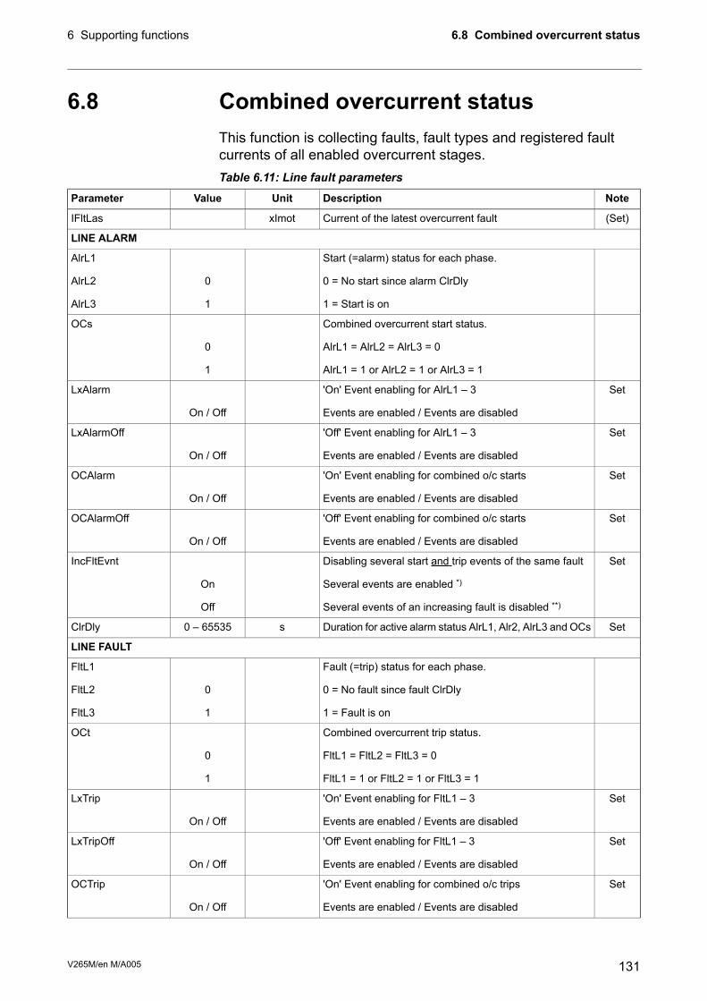
6.8 Combined overcurrent statusThis function is collecting faults, fault types and registered faultcurrents of all enabled overcurrent stages.Table 6.11: Line fault parameters
NoteDescriptionUnitValueParameter
(Set)Current of the latest overcurrent faultxImotIFltLas
LINE ALARM
Start (=alarm) status for each phase.-AlrL1
0 = No start since alarm ClrDly0AlrL2
1 = Start is on1AlrL3
Combined overcurrent start status.-OCs
AlrL1 = AlrL2 = AlrL3 = 00
AlrL1 = 1 or AlrL2 = 1 or AlrL3 = 11
Set'On' Event enabling for AlrL1 – 3-LxAlarm
Events are enabled / Events are disabledOn / Off
Set'Off' Event enabling for AlrL1 – 3-LxAlarmOff
Events are enabled / Events are disabledOn / Off
Set'On' Event enabling for combined o/c starts-OCAlarm
Events are enabled / Events are disabledOn / Off
Set'Off' Event enabling for combined o/c starts-OCAlarmOff
Events are enabled / Events are disabledOn / Off
SetDisabling several start and trip events of the same fault-IncFltEvnt
Several events are enabled *)On
Several events of an increasing fault is disabled **)Off
SetDuration for active alarm status AlrL1, Alr2, AlrL3 and OCss0 – 65535ClrDly
LINE FAULT
Fault (=trip) status for each phase.-FltL1
0 = No fault since fault ClrDly0FltL2
1 = Fault is on1FltL3
Combined overcurrent trip status.-OCt
FltL1 = FltL2 = FltL3 = 00
FltL1 = 1 or FltL2 = 1 or FltL3 = 11
Set'On' Event enabling for FltL1 – 3-LxTrip
Events are enabled / Events are disabledOn / Off
Set'Off' Event enabling for FltL1 – 3-LxTripOff
Events are enabled / Events are disabledOn / Off
Set'On' Event enabling for combined o/c trips-OCTrip
Events are enabled / Events are disabledOn / Off
131V265M/en M/A005
6.8 Combined overcurrent status6 Supporting functions

NoteDescriptionUnitValueParameter
Set'Off' Event enabling for combined o/c starts-OCTripOff
Events are enabled / Events are disabledOn / Off
SetDisabling several events of the same fault-IncFltEvnt
Several events are enabled *)On
Several events of an increasing fault is disabled **)Off
SetDuration for active alarm status FltL1, Flt2, FltL3 and OCts0 – 65535ClrDly
Set = An editable parameter (password needed).
*) Used with IEC 60870-105-103 communication protocol. The alarm screen will show the latest if it's the biggest registeredfault current, too. Not used with Spabus, because Spabus masters usually don't like to have unpaired On/Off events.
**) Used with SPA-bus protocol, because most SPA-bus masters do need an off-event for each corresponding on-event.
V265M/en M/A005132
6 Supporting functions6.8 Combined overcurrent status

6.9 Self-supervisionThe functions of the microcontroller and the associated circuitry, aswell as the program execution are supervised bymeans of a separatewatchdog circuit. Besides supervising the relay, the watchdog circuitattempts to restart the micro controller in an inoperable situation. Ifthe micro controller does not resart, the watchdog issues aself-supervision signal indicating a permanent internal condition.
When the watchdog circuit detects a permanent fault, it always blocksany control of other output relays (except for the self-supervisionoutput relay). In addition, the internal supply voltages are supervised.Should the auxiliary supply of the IED disappear, an indication isautomatically given because the IED status inoperative (SF) outputrelay functions on a working current principle. This means that theSF relay is energized when the auxiliary supply is on and the arcflash protection is healthy.
6.9.1 DiagnosticsThe device runs self-diagnostic tests for hardware and software inboot sequence and also performs runtime checking.
Permanent inoperative state
If permanent inoperative state has been detected, the device releasesSF relay contact and status LED is set on. Local panel will alsodisplay a detected fault message. Permanet inoperative state isentered when the device is not able to handle main functions.
Temporal inoperative state
When self-diagnostic function detects a temporal inoperative state,Selfdiag matrix signal is set and an event (E56) is generated. In casethe inoperative state was only temporary, an off event is generated(E57). Self diagnostic state can be reset via local HMI.
Diagnostic registers
There are four 16-bit diagnostic registers which are readable throughremote protocols. The following table shows the meaning of eachdiagnostic register and their bits.
133V265M/en M/A005
6.9 Self-supervision6 Supporting functions
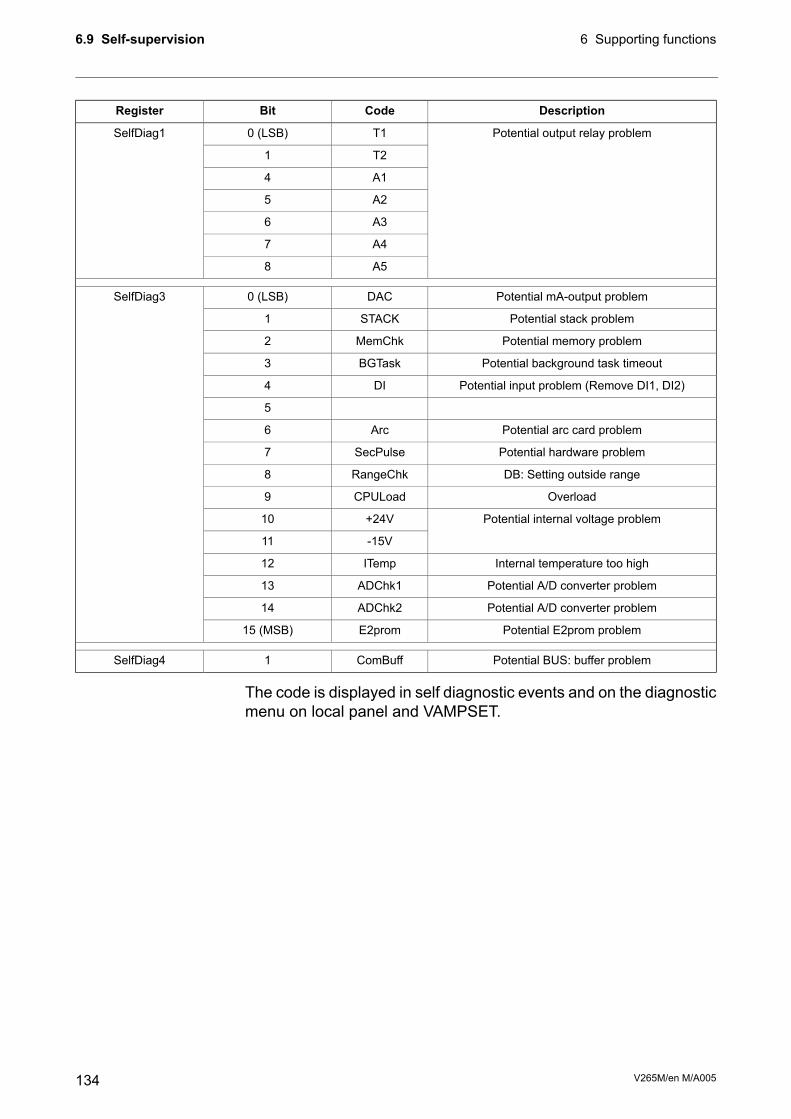
DescriptionCodeBitRegister
Potential output relay problemT10 (LSB)SelfDiag1
T21
A14
A25
A36
A47
A58
Potential mA-output problemDAC0 (LSB)SelfDiag3
Potential stack problemSTACK1
Potential memory problemMemChk2
Potential background task timeoutBGTask3
Potential input problem (Remove DI1, DI2)DI4
5
Potential arc card problemArc6
Potential hardware problemSecPulse7
DB: Setting outside rangeRangeChk8
OverloadCPULoad9
Potential internal voltage problem+24V10
-15V11
Internal temperature too highITemp12
Potential A/D converter problemADChk113
Potential A/D converter problemADChk214
Potential E2prom problemE2prom15 (MSB)
Potential BUS: buffer problemComBuff1SelfDiag4
The code is displayed in self diagnostic events and on the diagnosticmenu on local panel and VAMPSET.
V265M/en M/A005134
6 Supporting functions6.9 Self-supervision

7 Measurement functions
All the direct measurements are based on fundamental frequencyvalues. The exceptions are frequency and instantaneous current forarc protection.
The figure shows a current waveform and the correspondingfundamental frequency component f1, second harmonic f2 and rmsvalue in a special case, when the current deviates significantly froma pure sine wave.
0.00 0.05 0.10 0.15 0.20 0.25 0.30
-10
-5
0
5
rms
IL2
f1
f2
0
50
100
f2/f1 (%)Cu
rre
nt
(PU
)
Time (s)
Load = 0%
Re
lative
2n
d h
arm
oic
f2
/f1
(%
)
Figure 7.1: Example of various current values of a transformer inrush current
135V265M/en M/A005
7 Measurement functions

7.1 Measurement accuracyTable 7.1: Phase current inputs IL1, IL2, IL3, I’L1, I’L2, I’L3
25mA – 250 A (5A)Measuring range
5mA – 50 A (1A)
-Inaccuracy:
±0.5 % of value or ±15 mAI ≤ 7.5 A
±3 % of valueI > 7.5 A
The specified frequency range is 45 Hz – 65 Hz.
Squelch limit:
Phase current inputs: 0.5% of INOM (tolerance ±0.05%)
Residual current: 0.2% of I0NOM (tolerance ±0.05%)
Table 7.2: Residual current inputs I01, I020 – 5 x I0NMeasuring range
-Inaccuracy:
±0.3 % of value or ±0.2 % of I0NI ≤ 1.5 xIN
±3 % of valueI > 1.5 xINThe rated input I0N is 5A or 1A. This must be specified when ordering the relay.
The specified frequency range is 45 Hz – 65 Hz.
Table 7.3: Frequency16 Hz – 75 HzMeasuring range
±10 mHzInaccuracy
In VAMP 265M, the frequency is measured from current signals.
Table 7.4: THD and harmonics±2 % unitsInaccuracy I > 0.1 PU
Once a secondUpdate rate
The specified frequency range is 45 Hz – 65 Hz.
7.2 RMS valuesRMS currents
The device calculates the RMS value of each phase current. Theminimum and the maximum of RMS values are recorded and stored(see Chapter 7.5 Minimum and maximum values).
2
15
2
2
2
1...
fffRMSIIII +++=
V265M/en M/A005136
7 Measurement functions7.1 Measurement accuracy

7.3 Harmonics and Total HarmonicDistortion (THD)The device calculates the THDs as percentage of the base frequencyfor currents and voltages. The device calculates the harmonics fromthe 2nd to the 15th of phase currents and voltages. (The 17thharmonic component will also be shown partly in the value of the15th harmonic component. This is due to the nature of digitalsampling.)
The harmonic distortion is calculated using equation
Fundamental valueh1 =
Harmonicsh2 – 15 =
1
15
2
2
h
h
THDi
i∑=
=
Exampleh11 = 8 Ah7 = 3 A,h3 = 10 A,h1 = 100 A,
%2.13100
8310222
=++
=THD
For reference the RMS value is
ARMS 9.1008310100
2222=+++=
Another way to calculate THD is to use the RMS value as referenceinstead of the fundamental frequency value. In the example abovethe result would then be 13.0 %.
137V265M/en M/A005
7.3 Harmonics and Total Harmonic Distortion (THD)7 Measurement functions

7.4 Demand valuesThe relay calculates average, i.e. demand values of phase currentsIL1, IL2, IL3.
The demand time is configurable from 10minutes to 30 minutes withparameter "Demand time".Table 7.5: Demand value parameters
SetDescriptionUnitValueParameter
SetDemand time (averaging time)min10 – 30Time
Fundamental frequency values
Demand of phase current IL1AIL1da
Demand of phase current IL2AIL2da
Demand of phase current IL3AIL3da
RMS values
Demand of phase current IL1AIL1da
Demand of phase current IL2AIL2da
Demand of phase current IL3AIL3da
Set = An editable parameter (password needed).
7.5 Minimum and maximum valuesMinimum andmaximum values are registered with time stamps sincethe latest manual clearing or since the device has been restarted.The available registered min & max values are listed in the followingtable.
DescriptionMin & Max measurement
Phase current (fundamental frequency value)IL1, IL2, IL3
Phase current, rms valueIL1RMS, IL2RMS, IL3RMS
Residual currentI01, I02Frequencyf
Demand values of phase currentsIL1da, IL2da, IL3da
Demand values of phase currents, rms valuesIL1da, IL2da, IL3da (rms value)
The clearing parameter "ClrMax" is common for all these values.Table 7.6: Parameters
SetDescriptionValueParameter
SetReset all minimum and maximum values-
-
Clear
ClrMax
V265M/en M/A005138
7 Measurement functions7.4 Demand values
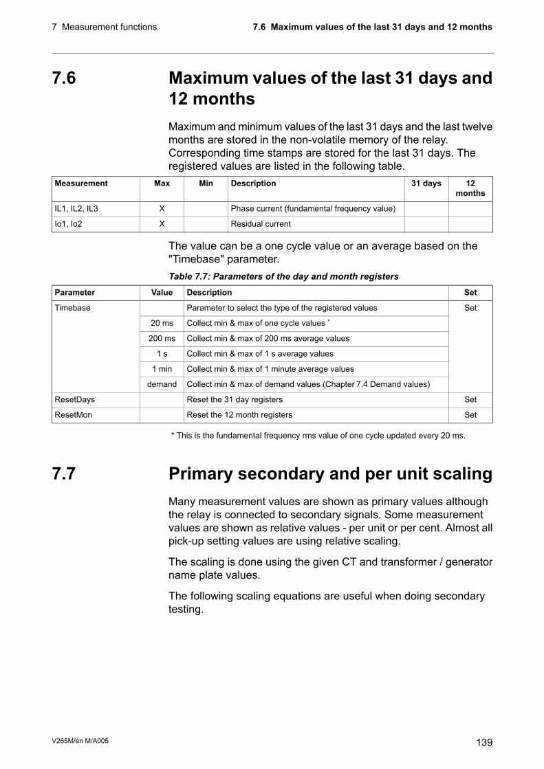
7.6 Maximum values of the last 31 days and12 monthsMaximum andminimum values of the last 31 days and the last twelvemonths are stored in the non-volatile memory of the relay.Corresponding time stamps are stored for the last 31 days. Theregistered values are listed in the following table.
12months
31 daysDescriptionMinMaxMeasurement
Phase current (fundamental frequency value)XIL1, IL2, IL3
Residual currentXIo1, Io2
The value can be a one cycle value or an average based on the"Timebase" parameter.Table 7.7: Parameters of the day and month registers
SetDescriptionValueParameter
SetParameter to select the type of the registered valuesTimebase
Collect min & max of one cycle values *20 ms
Collect min & max of 200 ms average values200 ms
Collect min & max of 1 s average values1 s
Collect min & max of 1 minute average values1 min
Collect min & max of demand values (Chapter 7.4 Demand values)demand
SetReset the 31 day registersResetDays
SetReset the 12 month registersResetMon
* This is the fundamental frequency rms value of one cycle updated every 20 ms.
7.7 Primary secondary and per unit scalingMany measurement values are shown as primary values althoughthe relay is connected to secondary signals. Some measurementvalues are shown as relative values - per unit or per cent. Almost allpick-up setting values are using relative scaling.
The scaling is done using the given CT and transformer / generatorname plate values.
The following scaling equations are useful when doing secondarytesting.
139V265M/en M/A005
7.6 Maximum values of the last 31 days and 12 months7 Measurement functions

7.7.1 Current scaling
NOTE: The rated value of the device's current input, for example 5 A or 1A,does not have any effect in the scaling equations, but it defines themeasurement range and the maximum allowed continuous current.See Table 12.1 for details.
Primary and secondary scalingCurrent scaling
SEC
PRI
SECPRI
CT
CTII ⋅=secondary → primary
PRI
SEC
PRISEC
CT
CTII ⋅=primary → secondary
For residual current to input I01 or I02 use the corresponding CTPRIand CTSEC values. For ground fault stages using I0Calc signals usethe phase current CT values for CTPRI and CTSEC.
Examples:
1. Secondary to primaryCT = 500 / 5Current to the relay's input is 4 A.=> Primary current is IPRI = 4 x 500 / 5 = 400 A
2. Primary to secondaryCT = 500 / 5The relay displays IPRI = 400 A=> Injected current is ISEC = 400 x 5 / 500 = 4 A
Per unit [pu] scaling
For phase currents excluding ArcI> stage:
1 pu = 1 x IMOT = 100%, where IMOT is the rated current of the motor.
The rated current for high voltage side (HV) and low voltages side(LV) are calculated by the device itself using Equation 7.1.
IMOT = The rated current 1 pu.Equation 7.1:
MOT
MOT
U
S
MOT
⋅
=
3
I
SMOT = Rated apparent power of the protected device
UMOT = Rated line-to-line voltage of the protected device
V265M/en M/A005140
7 Measurement functions7.7 Primary secondary and per unit scaling

For residual currents
1 pu = 1 x CTSEC for secondary side and 1 pu = 1 x CTPRI for primaryside.
Residual current (3I0) scaling and phasecurrent scaling for ArcI> stage
Phase current scaling excluding ArcI> stage
SEC
SEC
PU
CT
II =
MOTSEC
PRISEC
PU
ICT
CTII
⋅
⋅=secondary → per unit
SECPUSEC
CTII ⋅=
PRI
MOT
SECPUSEC
CT
ICTII ⋅⋅=per unit → secondary
Examples:
1. Secondary to per unit and percent for phase currentsexcluding ArcI>.CTPRI = 150/1CTSEC = 800/5SMOT = 25 MVAUMOT = 110 kVU'MOT = 21 kVCurrent injected to the relay's primary side input is 175 mA and859 mA for the secondary side input.The rated current on HV and LV side will beIMOT = 25 MVA/( 3 x 110 kV) = 131.2 AI'MOT = 25 MVA/( 3 x 21 kV) = 687.3 APer unit currents areIPU = 0.175 x 150 / (1 x 131.2) = 0.20 pu = 20 % x IMOT (HV side)I'PU = 0.859 x 800 / (5 x 687.3) = 0.20 pu = 20 % (LV side)
2. Secondary to per unit for ArcI>.CT = 750 / 5Current injected to the relay's inputs is 7 A.Per unit current is IPU = 7 / 5 = 1.4 pu = 140 %
3. Per unit and percent to secondary for phase currentsexcluding ArcI>.CTPRI = 150 / 1CTSEC = 800 / 5SMOT = 25 MVAUMOT = 110 kVU'MOTMOT = 21 kVThe relay setting is 0.20 pu = 20 % x IMOT.The rated current on HV and LV side will be same as in example1.The corresponding secondary currents areISEC = 0.20 x IMOT = 0.20 x 131.2 x 1 / 150 = 175 mA (HV side)I'SEC = 0.20 x I'MOT = 0.20 x 687.3 x 5 / 800 = 859 mA (LV side)
141V265M/en M/A005
7.7 Primary secondary and per unit scaling7 Measurement functions

4. Per unit to secondary for ArcI>.CT = 750 / 5The relay setting is 2 pu = 200 %.Secondary current is ISEC = 2 x 5 = 10 A
5. Secondary to per unit for residual current.Input is I01 or I02.CT0 = 50 / 1Current injected to the relay's input is 30 mA.Per unit current is IPU = 0.03 / 1 = 0.03 pu = 3 %
6. Per unit to secondary for residual current.Input is I01 or I02.CT0 = 50 / 1The relay setting is 0.03 pu = 3 %.Secondary current is ISEC = 0.03 x 1 = 30 mA
7. Secondary to per unit for residual current.Input is I0Calc.CT = 750 / 5Currents injected to the relay's IL1 input is 0.5 A.IL2 = IL3 = 0.Per unit current is IPU = 0.5 / 5 = 0.1 pu = 10 %
8. Per unit to secondary for residual current.Input is I0Calc.CT = 750 / 5The relay setting is 0.1 pu = 10 %.If IL2 = IL3 = 0, then secondary current to IL1 is ISEC = 0.1 x 5 =0.5 A
V265M/en M/A005142
7 Measurement functions7.7 Primary secondary and per unit scaling
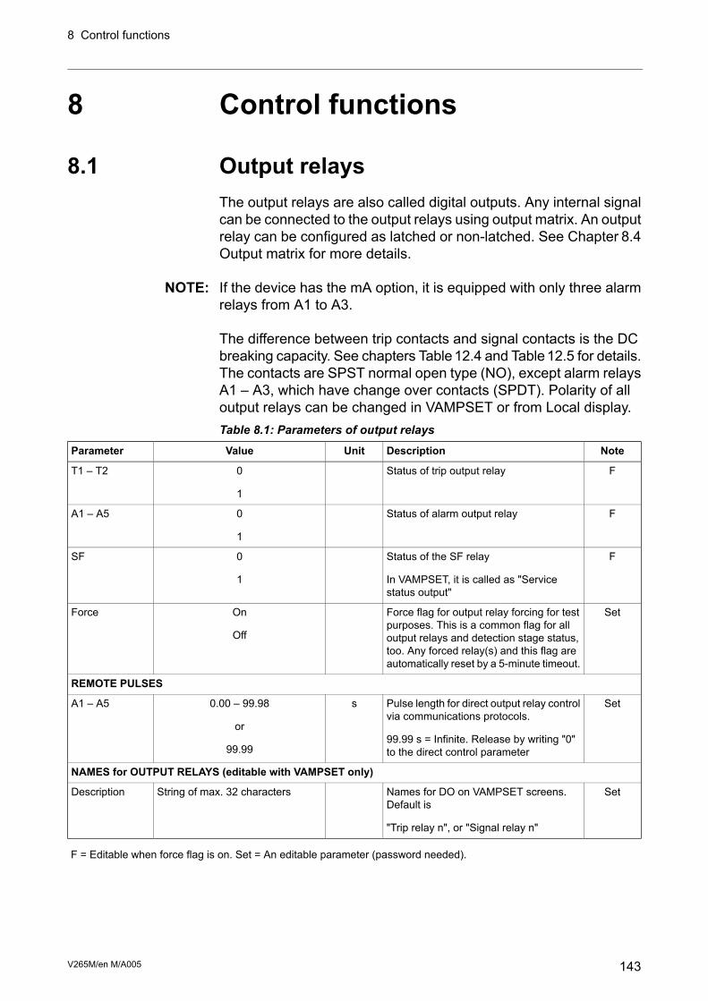
8 Control functions
8.1 Output relaysThe output relays are also called digital outputs. Any internal signalcan be connected to the output relays using output matrix. An outputrelay can be configured as latched or non-latched. See Chapter 8.4Output matrix for more details.
NOTE: If the device has the mA option, it is equipped with only three alarmrelays from A1 to A3.
The difference between trip contacts and signal contacts is the DCbreaking capacity. See chapters Table12.4 and Table12.5 for details.The contacts are SPST normal open type (NO), except alarm relaysA1 – A3, which have change over contacts (SPDT). Polarity of alloutput relays can be changed in VAMPSET or from Local display.Table 8.1: Parameters of output relays
NoteDescriptionUnitValueParameter
FStatus of trip output relay0
1
T1 – T2
FStatus of alarm output relay0
1
A1 – A5
FStatus of the SF relay
In VAMPSET, it is called as "Servicestatus output"
0
1
SF
SetForce flag for output relay forcing for testpurposes. This is a common flag for alloutput relays and detection stage status,too. Any forced relay(s) and this flag areautomatically reset by a 5-minute timeout.
On
Off
Force
REMOTE PULSES
SetPulse length for direct output relay controlvia communications protocols.
99.99 s = Infinite. Release by writing "0"to the direct control parameter
s0.00 – 99.98
or
99.99
A1 – A5
NAMES for OUTPUT RELAYS (editable with VAMPSET only)
SetNames for DO on VAMPSET screens.Default is
"Trip relay n", or "Signal relay n"
String of max. 32 charactersDescription
F = Editable when force flag is on. Set = An editable parameter (password needed).
143V265M/en M/A005
8 Control functions

8.2 Digital inputsThere are 6 digital inputs available for control purposes. The polarity- normal open (NO) / normal closed (NC) - and a delay can beconfigured according the application. The signals are available forthe output matrix, block matrix, user's programmable logic etc.
The contacts connected to digital inputs DI1 – DI6 must be dry(potential free). These inputs use the common internal 48 Vdc wettingvoltage from pin X3:1, only.
NOTE: These digital inputs must not be connected parallel with inputs ofanother device.
Table 8.2: Summary of digital inputs:AvailabilityOperating voltagePinsDI
48VDC supply for DI1 – 6X3:1<-
Internal 48V dc
X3:21
X3:32
X3:43
X3:54
X3:65
X3:76
ARC card with 2 DIsExternal 18 – 265 V dc
50 – 250 V ac
X6:1 – 219
ARC card with 2 DIsExternal 18 – 265 V dc
50 – 250 V ac
X6:3 – 420
Label and description texts can be edited with VAMPSET accordingthe application. Labels are the short parameter names used on thelocal panel and descriptions are the longer names used byVAMPSET.
V265M/en M/A005144
8 Control functions8.2 Digital inputs

Table 8.3: Parameters of digital inputsNoteDescriptionUnitValueParameter
Status of digital input0; 1DI1 – DI6
DI COUNTERS
(Set)Cumulative active edge counter0 – 65535DI1 – DI6
DELAYS FOR DIGITAL INPUTS
SetDefinite delay for both on and off transitionss0.00 – 60.00DI1 – DI6
CONFIGURATION DI1 – DI6
SetFor normal open contacts (NO). Active edge is0 -> 1
noInverted
For normal closed contacts (NC). Active edgeis 1 -> 0
yes
SetNo pop-up displaynoIndication display
Indication display is activated at active DI edgeyes
SetActive edge event enabledOnOn event
Active edge event disabledOff
SetInactive edge event enabledOnOff event
Inactive edge event disabledOff
NAMES for DIGITAL INPUTS (editable with VAMPSET only)
SetShort name for DIs on the local display. Defaultis
"DIn", n = 1 – 6
String of max. 10 charactersLabel
SetLong name for DIs. Default is
"Digital input n", n = 1 – 6
String of max. 32 charactersDescription
Set = An editable parameter (password needed).
145V265M/en M/A005
8.2 Digital inputs8 Control functions

8.3 Virtual inputs and outputsThere are four virtual inputs and six virtual outputs. The four virtualinputs acts like normal digital inputs. The state of the virtual inputcan be changed from display, communication bus and fromVAMPSET. For example setting groups can be changed using virtualinputs.Table 8.4: Parameters of virtual inputs
NoteDescriptionUnitValueParameter
Status of virtual input0; 1VI1 – VI4
SetEvent enablingOn; OffEvents
NAMES for VIRTUAL INPUTS (editable with VAMPSET only)
SetShort name for VIs on the local displayString of max. 10 charactersLabel
Default is "VIn", n = 1 – 4
SetLong name for VIs. Default is "Virtual input n",n = 1 – 4
String of max. 32 charactersDescription
Set = An editable parameter (password needed).
The six virtual outputs do act like output relays, but there are nophysical contacts. Virtual outputs are shown in the output matrix andthe block matrix. Virtual outputs can be used with the user'sprogrammable logic and to change the active setting group etc.
V265M/en M/A005146
8 Control functions8.3 Virtual inputs and outputs

8.4 Output matrixBy means of the output matrix, the output signals of the variousprotection stages, digital inputs, logic outputs and other internalsignals can be connected to the output relays, front panel indicators,virtual outputs etc.
There are two LED indicators named "Alarm" and "Trip" on the frontpanel. Furthermore there are three general purpose LED indicators- "A", "B" and "C" - available for customer-specific indications. Inaddition, the triggering of the disturbance recorder (DR) and virtualoutputs are configurable in the output matrix. See an example inFigure 8.1.
An output relay or indicator LED can be configured as latched ornon-latched. A non-latched relay follows the controlling signal. Alatched relay remains activated although the controlling signalreleases.
There is a common "release latched" signal to release all the latchedrelays. This release signal resets all the latched output relays andindicators. The reset signal can be given via a digital input, via akeypad or through communication. Any digital input can be used forresetting. The selection of the input is done with the VAMPSETsoftware under the menu "Release output matrix latches". Under thesame menu, the "Release latches" parameter can be used forresetting.
OUTPUT MATRIX
connected
I> start
I>> start
Io> start
Io>> start
I> trip
I>> trip
Io> trip
Io>> trip
T1 T2 A1 A2 A3 A4 A5 Alarm Trip A B C DR VO1
connected and latched
OutputMatrix
Figure 8.1: Output matrix.
147V265M/en M/A005
8.4 Output matrix8 Control functions

8.5 Blocking matrixBy means of a blocking matrix, the operation of any protection stagecan be blocked. The blocking signal can originate from the digitalinputs DI1 to DI6, or it can be a start or trip signal from a protectionstage or an output signal from the user's programmable logic. In theblock matrix Figure 8.2 an active blocking is indicated with a blackdot () in the crossing point of a blocking signal and the signal to beblocked.
Figure 8.2: Blocking matrix and output matrix
V265M/en M/A005148
8 Control functions8.5 Blocking matrix

8.6 Controllable objectsThe device allows controlling of six objects, that is, circuit-breakers,disconnectors and grounding switches. Controlling can be done by"select-execute" or "direct control" principle.
The object block matrix and logic functions can be used to configureinterlocking for a safe controlling before the output pulse is issued.The objects 1 – 6 are controllable while the objects 7 – 8 are onlyable to show the status.
Controlling is possible by the following ways:
• through the local HMI
• through a remote communication
• through a digital input
The connection of an object to specific output relays is done via anoutput matrix (object 1 – 6 open output, object 1 – 6 close output).There is also an output signal “Object failed”, which is activated ifthe control of an object is not completed.
Object states
Each object has the following states:DescriptionValueSetting
Actual state of the objectUndefined (00)Object state
Open
Close
Undefined (11)
Basic settings for controllable objects
Each controllable object has the following settings:DescriptionValueSetting
Open informationNone, any digital input, virtual input or virtualoutput
DI for ‘obj open’
Close informationDI for ‘obj close’
Ready informationDI for ‘obj ready’
Pulse length for open and close commands0.02 – 600 sMax ctrl pulse length
Timeout of ready indication0.02 – 600 sCompletion timeout
Direct object controlOpen/CloseObject control
If changing states takes longer than the time defined by “Max ctrlpulse length” setting, object is inoperative and “Object failure” matrixsignal is set. Also undefined-event is generated. “Completion timeout”is only used for the ready indication. If “DI for ‘obj ready’” is not set,completion timeout has no meaning.
149V265M/en M/A005
8.6 Controllable objects8 Control functions

Each controllable object has 2 control signals in matrix:DescriptionOutput signal
Open control signal for the objectObject x Open
Close control signal for the objectObject x Close
These signals send control pulse when an object is controlled bydigital input, remote bus, auto-reclose etc.
Settings for read-only objectsDescriptionValueSetting
Open informationNone, any digital input, virtual input or virtualoutput
DI for ‘obj open’
Close informationDI for ‘obj close’
Timeout for state changes0.02 – 600 sObject timeout
If changing states takes longer than the time defined by “Objecttimeout” setting, and “Object failure” matrix signal is set. Alsoundefined-event is generated.
8.6.1 Controlling with DIObjects can be controlled with digital input, virtual input or virtualoutput. There are four settings for each controllable object:
ActiveSetting
In remote stateDI for remote open / close control
In local stateDI for local open / close control
If the device is in local control state, the remote control inputs areignored and vice versa. Object is controlled when a rising edge isdetected from the selected input. Length of digital input pulse shouldbe at least 60 ms.
8.6.2 Local/Remote selectionIn Local mode, the output relays can be controlled via a local HMI,but they cannot be controlled via a remote serial communicationinterface.
In Remote mode, the output relays cannot be controlled via a localHMI, but they can be controlled via a remote serial communicationinterface.
The selection of the Local/Remote mode is done by using a localHMI, or via one selectable digital input. The digital input is normallyused to change a whole station to a local or remote mode. Theselection of the L/R digital input is done in the “Objects” menu of theVAMPSET software.
NOTE: A password is not required for a remote control operation.
V265M/en M/A005150
8 Control functions8.6 Controllable objects

8.7 Logic functionsThe device supports customer-defined programmable logic forboolean signals. The logic is designed by using the VAMPSET settingtool and downloaded to the device. Functions available are:
• COUNTERs
• RS & D flip-flops
• XOR
• NOT
• AND
• OR
Logic is made with VAMPSET setting tool. Consumed memory isdynamically shown on the configuration view in percentage. The firstvalue indicates amount of used inputs, second amount of gates andthird values shows amount of outputs consumed.
Figure 8.3: Logic can be found and modified in “logic” menu in VAMPSET setting tool
Percentages show used memory amount.
Inputs/Logical functions/Outputs- used. None of these is not allowedto exceed 100%. See guide below to learn basics of logic creation:
1
4
2
3
Figure 8.4: How to create logical nodes.
1. Press empty area to add a logic gate, confirm new function bypressing “Yes”.
2. Logic function is always "AND" -gate as a default.
3. While logic increases the capacity is increasing as well.
4. To joint logic functions, go on top of the output line of gate andhold down mouse left -> make the connection to other logicfunctions input.
151V265M/en M/A005
8.7 Logic functions8 Control functions

6
31
2
4
5
Figure 8.5: Logic creation.
1. Left click on top of any logic function to activate the “Selectoperation” view.
2. Edit properties button opens the “Function properties” window.
3. Generally it is possible to choose the type of logic functionbetween and/or/counter/swing -gate.
4. When counter is selected, count setting may be set here.
5. Separate delay setting for logic activation and dis-activation.
6. Possible to invert the output of logic. Inverted logic output ismarked with circle.
1
2
3
4
Figure 8.6: Logic creation
1. Select input signals can be done by pressing the following buttonor by clicking mouse left on top of the logic input line.
2. Select outputs can be done by pressing the following button orby clicking mouse left on top of the logic output line.
3. This deletes the logic function.
4. When logic is created and settings are written to the IED the unitrequires a restart. After restarting the logic output is automaticallyassigned in output matrix as well.
NOTE: Whenever writing new logic to the IED the unit has to be restarted.
V265M/en M/A005152
8 Control functions8.7 Logic functions
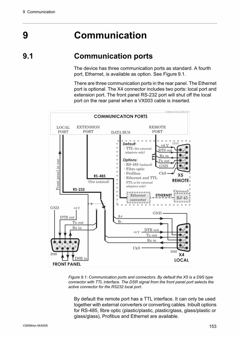
9 Communication
9.1 Communication portsThe device has three communication ports as standard. A fourthport, Ethernet, is available as option. See Figure 9.1.
There are three communication ports in the rear panel. The Ethernetport is optional. The X4 connector includes two ports: local port andextension port. The front panel RS-232 port will shut off the localport on the rear panel when a VX003 cable is inserted.
123456789
X4
LOCAL
X5
REMOTE
1
1
5
D9S
D9S
6
6
7
7
8
8
9
95
2
2
3
3
4
4
RJ-45
D9S
Fro
nt
pan
el
in u
se
Rx in
Rx in
Tx out
RTS out
GND
CkS
CkS
+8 V
DSR in
LOCAL
PORT
EXTENSION
PORT DATA BUS
REMOTE
PORT
Tx out
Tx out
Rx inTTL
DTR out
B-
(Not isolated)
A+
RS-485
RS-232
ETHERNET
GNDDTR out
+8 V
+8 V
GND
FRONT PANEL
COMMUNICATION PORTS
Default
Options
:
- TTL
:
- RS-485
- Fibre optic
- Profibus
- Ethernet and TTL
(for external
adapters only)
(isolated)
(TTL is for external
adapters only)
(Optional)
CommunicationPorts
Ethernet
converter
Figure 9.1: Communication ports and connectors. By default the X5 is a D9S typeconnector with TTL interface. The DSR signal from the front panel port selects theactive connector for the RS232 local port.
By default the remote port has a TTL interface. It can only be usedtogether with external converters or converting cables. Inbuilt optionsfor RS-485, fibre optic (plastic/plastic, plastic/glass, glass/plastic orglass/glass), Profibus and Ethernet are available.
153V265M/en M/A005
9 Communication

9.1.1 Local port X4The local port has two connectors:
• On the front panel
• X4 the rear panel (D9S pins 2, 3 and 5)
Only one can be used at a time.
NOTE: The extension port is locating in the same X4 connector.
When the VX003 cable is inserted to the front panel connector itactivates the front panel port and disables the rear panel local portby connecting the DTR pin 6 and DSR pin 4 together. See Figure9.1.
Protocol for the local port
The front panel port is always using the command line protocol forVAMPSET regardless of the selected protocol for the rear panel localport.
If other than "None" protocol is selected for the rear panel local port,the front panel connector, when activated, is still using the plaincommand line interface with the original speed, parity etc. Forexample if the rear panel local port is used for remote VAMPSETcommunication using SPA-bus default 9600/7E1, it is possible totemporarily connect a PCwith VAMPSET to the front panel connectorwith the default 38400/8N1. While the front panel connector is inuse, the rear panel local port is disabled. The communicationparameter display on the local display will show the active parametervalues for the local port.
Physical interface
The physical interface of this port is RS-232.
V265M/en M/A005154
9 Communication9.1 Communication ports

Table 9.1: ParametersNoteDescriptionUnitValueParameter
SetProtocol selection for the rear panel local port.Protocol
Command line interface for VAMPSETNone
SPA-bus (slave)SpaBus
Profibus DB (slave)ProfibusDP
Modbus RTU slaveModbusSla
Modbus TCP slaveModbusTCPs
IEC-60870-5-103 (slave)IEC-103
Modbus RTU master for external I/O-modulesExternalIO
DNP 3.0DNP3
ClrMessage counter since the device has restartedor since last clearing
0 – 232-1Msg#
ClrProtocol errors since the device has restartedor since last clearing
0 – 216-1Errors
ClrTimeout errors since the device has restartedor since last clearing
0 – 216-1Tout
1)Display of actual communication parameters.
Speed = bit/s
D = number of data bits
P = parity: none, even, odd
S = number of stop bits
-
speed/DPS
Default = 38400/8N1 forVAMPSET
VAMPSET communication (Direct or SPA-bus embedded command line interface)
Unsent bytes in transmitter buffer/size of thebuffer
bytes/sizeTx
ClrMessage counter since the device has restartedor since last clearing
0 – 232-1Msg#
ClrErrors since the device has restarted or sincelast clearing
0 – 216-1Errors
ClrTimeout errors since the device has restartedor since last clearing
0 – 216-1Tout
Set = An editable parameter (password needed). Clr = Clearing to zero is possible.
1) The communication parameters are set in the protocol specific menus. For the local port command line interface theparameters are set in configuration menu.
155V265M/en M/A005
9.1 Communication ports9 Communication

9.1.2 Remote port X5
Physical interface
The physical interface of this port depends of the communicationletter in the order code. See Figure 9.1, Chapter 11.3.2 Rear panelconnector X5 (REMOTE) and the table below. The TTL interface isfor external converters and converter cables only. It is not suitablefor direct connection to distances more than one meter.Table 9.2: Parameters
NoteDescriptionUnitValueParameter
SetProtocol selection for remote portProtocol
-None
SPA-bus slaveSPA-bus
Profibus DB slaveProfibusDP
Modbus RTU slaveModbusSla
Modbus TCP slaveModbusTCPs
IEC-60870-5-103 slaveIEC-103
Modbus RTU master for external I/O-modulesExternalIO
DNP 3.0DNP3
ClrMessage counter since the device has restarted orsince last clearing
0 – 232-1Msg#
ClrProtocol errors since the device has restarted or sincelast clearing
0 – 216-1Errors
ClrTimeout errors since the device has restarted or sincelast clearing
0 – 216-1Tout
1)Display of current communication parameters.
Speed = bit/s
D = number of data bits
P = parity: none, even, odd
S = number of stop bits
-
speed/DPS
SetEcho to local port
No echo
For binary protocols
For SPA-bus protocol
-
No
Binary
ASCII
Debug
Set = An editable parameter (password needed). Clr = Clearing to zero is possible.
1) The communication parameters are set in the protocol specific menus. For the local port command line interface theparameters are set in configuration menu.
V265M/en M/A005156
9 Communication9.1 Communication ports

9.1.3 Extension port X4This is a non-isolated RS-485 port for external I/O devices. The portis located in the same rear panel D9S connector X4 as the local port,but pins (7, 8, 5) are used instead of the standard RS-232 pins (2,3, 5) used by the local port. See Figure 9.1.Table 9.3: Parameters
NoteDescriptionUnitValueParameter
SetProtocol selection for extension portProtocol
Command line interface for VAMPSETNone
SPA-bus slaveSPA-bus
Profibus DB slaveProfibusDP
Modbus RTU slaveModbusSla
Modbus TCP slaveModbusTCPs
IEC-60870-5-103 slaveIEC-103
Modbus RTU master for external I/O-modulesExternalIO
DNP 3.0DNP3
ClrMessage counter since the device has restarted orsince last clearing
0 – 232-1Msg#
ClrProtocol errors since the device has restarted or sincelast clearing
0 – 216-1Errors
ClrTimeout errors since the device has restarted or sincelast clearing
0 – 216-1Tout
1)Display of current communication parameters.
Speed = bit/s
D = number of data bits
P = parity: none, even, odd
S = number of stop bits
-
speed/DPS
Default = 38400/8N1for VAMPSET
Set = An editable parameter (password needed). Clr = Clearing to zero is possible.
1) The communication parameters are set in the protocol specific menus. For the local port command line interface theparameters are set in configuration menu.
157V265M/en M/A005
9.1 Communication ports9 Communication

9.1.4 Ethernet portTCP port 1st INST and TCP port 2nd INST are ports for ethernetcommunication protocols. Ethernet communication protocols can beselected to these ports when such hardware option is installed. Theparameters for these ports are set via local HMI or with VAMPSETin menus TCP port 1st INST and TCP port 2nd INST. Two differentprotocols can be used simultaneously on one physical interface (bothprotocols use the same IP address and MAC address but differentIP port).
Protocol configuration menu contains address and other relatedinformation for the ethernet port. TCP port 1st and 2nd instanceinclude selection for the protocol, IP port settings andmessage/error/timeout counters. More information about the protocolconfiguration menu on table below.Table 9.4: Main configuration parameters (local display), inbuilt Ethernetport
NoteDescriptionUnitValueParameter
SetProtocol selection for the extension portProtocol
Command line interface for VAMPSETNone
Modbus TCP slaveModbusTCPs
IEC-101IEC-101
IEC-61850 protocolIEC 61850
Ethernet/IP protocolEtherNet/IP
DNP/TCPDNP3
SetIp port for protocol, default 102nnnPort
SetInternet protocol address (set withVAMPSET)
n.n.n.nIpAddr
SetNet mask (set with VAMPSET)n.n.n.nNetMsk
SetGateway IP address (set with VAMPSET)default = 0.0.0.0Gatew
SetNetwork time protocol server (set withVAMPSET)
n.n.n.nNTPSvr
0.0.0.0 = no SNTP
Set (1TCP keepalive intervalnnKeepAlive
SetEnable FTP serveron/offFTP server
SetMaximum transmission speed for FTP4 Kb/s (default)FTP speed
SetFTP password? (user)FTP password
config (configurator)
MAC address001ADnnnnnnnMAC address
SetIP port for VampsetnnVS Port
23 (default)
Message counternnnMsg#
Error counternnnErrors
Timeout counternnnTout
V265M/en M/A005158
9 Communication9.1 Communication ports

NoteDescriptionUnitValueParameter
SetSniffer port enableon/offEthSffEn
Sniffer portPort2SniffPort
Set = An editable parameter (password needed)
1) KeepAlive: The KeepAlive parameter sets in seconds the time between two keepalive packets that are sent from theIED. The setting range for this parameter is between zero (0) and 20 seconds; with the exception that zero (0) meansactually 120 seconds (2 minutes). A keep alive’s packet purpose is for the VAMP IED to send a probe packet to a connectedclient for checking the status of the TCP-connection when no other packet is being sent e.g. client does not poll data fromthe IED. If the keepalive packet is not acknowledged, the IED will close the TCP connection. Connection must be resumedon the client side.
Table 9.5: TCP PORT 1st INSTNoteDescriptionUnitValueParameter
SetProtocol selection for the extension port.Protocol
Command line interface for VAMPSETNone
Modbus TCP slaveModbusTCPs
IEC-61850 protocolIEC 61850
Ethernet/IP protocolEtherNet/IP
DNP/TCPDNP3
SetIp port for protocol, default 502nnnPort
Message counternnnMsg#
Error counternnnErrors
Timeout counternnnTout
Table 9.6: CP PORT 2nd INSTNoteDescriptionUnitValueParameter
SetProtocol selection for the extension port.Ethernet port protocol
(TCP PORT 2nd INST) Command line interface for VAMPSETNone
Modbus TCP slaveModbusTCPs
IEC-61850 protocolIEC 61850
Ethernet/IP protocolEtherNet/IP
DNP/TCPDNP3
SetIp port for protocol, default 502nnnPort
Message counternnnMsg#
Error counternnnErrors
Timeout counternnnTout
Set = An editable parameter (password needed).
159V265M/en M/A005
9.1 Communication ports9 Communication

9.2 Communication protocolsThe protocols enable the transfer of the following type of data:
• events
• status information
• measurements
• control commands.
• clock synchronizing
• Settings (SPA-bus and embedded SPA-bus only)
9.2.1 PC communicationPC communication is using a VAMP specified command lineinterface. The VAMPSET program can communicate using the localRS-232 port or using ethernet interface.
It is also possible to select SPA-bus protocol for the local port andconfigure the VAMPSET to embed the command line interface insideSPA-bus messages.
For Ethernet configuration, see Chapter 9.1.4 Ethernet port.
V265M/en M/A005160
9 Communication9.2 Communication protocols

9.2.2 Modbus TCP and Modbus RTUThese Modbus protocols are often used in power plants and inindustrial applications. The difference between these two protocolsis the media. Modbus TCP uses Ethernet and Modbus RTU usesasynchronous communication (RS-485, optic fibre, RS-232).
VAMPSET will show the list of all available data items for Modbus.
The Modbus communication is activated usually for remote port viaa menu selection with parameter "Protocol". See Chapter 9.1Communication ports.
For ethernet interface configuration, see Chapter9.1.4 Ethernet port.Table 9.7: Parameters
NoteDescriptionUnitValueParameter
SetModbus address for the device.
Broadcast address 0 can be used for clock synchronizing.Modbus TCP uses also the TCP port settings.
1 – 247Addr
SetCommunication speed for Modbus RTUbps1200
2400
4800
9600
19200
bit/s
SetParity for Modbus RTUNone
Even
Odd
Parity
Set = An editable parameter (password needed)
161V265M/en M/A005
9.2 Communication protocols9 Communication

9.2.3 Profibus DPThe Profibus DP protocol is widely used in industry. An external VPA3CG is required.
Device profile "continuous mode"
In this mode, the device is sending a configured set of dataparameters continuously to the Profibus DP master. The benefit ofthis mode is the speed and easy access to the data in the Profibusmaster. The drawback is the maximum buffer size of 128 bytes,which limits the number of data items transferred to the master. SomePLCs have their own limitation for the Profibus buffer size, whichmay further limit the number of transferred data items.
Device profile "Request mode"
Using the request mode it is possible to read all the available datafrom the VAMP device and still use only a very short buffer forProfibus data transfer. The drawback is the slower overall speed ofthe data transfer and the need of increased data processing at theProfibus master as every data item must be separately requestedby the master.
NOTE: In request mode, it is not possible to read continuously only onesingle data item. At least two different data items must be read inturn to get updated data from the device.
There is a separate manual for VPA 3CG (VVPA3CG/EN M/xxxx)for the continuous mode and request mode. The manual is availableto download from our website.
Available data
VAMPSETwill show the list of all available data items for both modes.A separate document “Profibus parameters.pdf” is also available.
The Profibus DP communication is activated usually for remote portvia a menu selection with parameter "Protocol". See Chapter 9.1Communication ports.
V265M/en M/A005162
9 Communication9.2 Communication protocols
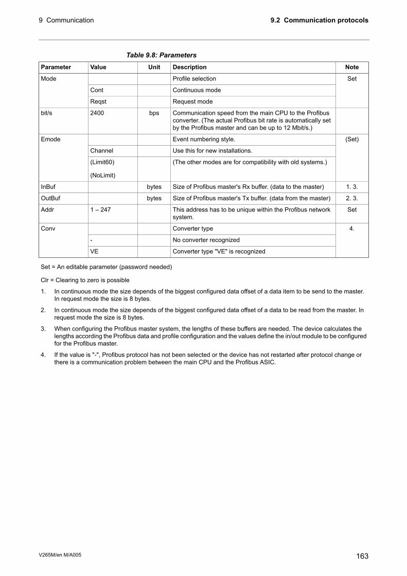
Table 9.8: ParametersNoteDescriptionUnitValueParameter
SetProfile selectionMode
Continuous modeCont
Request modeReqst
Communication speed from the main CPU to the Profibusconverter. (The actual Profibus bit rate is automatically setby the Profibus master and can be up to 12 Mbit/s.)
bps2400bit/s
(Set)Event numbering style.Emode
Use this for new installations.Channel
(The other modes are for compatibility with old systems.)(Limit60)
(NoLimit)
1. 3.Size of Profibus master's Rx buffer. (data to the master)bytesInBuf
2. 3.Size of Profibus master's Tx buffer. (data from the master)bytesOutBuf
SetThis address has to be unique within the Profibus networksystem.
1 – 247Addr
4.Converter typeConv
No converter recognized-
Converter type "VE" is recognizedVE
Set = An editable parameter (password needed)
Clr = Clearing to zero is possible
1. In continuous mode the size depends of the biggest configured data offset of a data item to be send to the master.In request mode the size is 8 bytes.
2. In continuous mode the size depends of the biggest configured data offset of a data to be read from the master. Inrequest mode the size is 8 bytes.
3. When configuring the Profibus master system, the lengths of these buffers are needed. The device calculates thelengths according the Profibus data and profile configuration and the values define the in/out module to be configuredfor the Profibus master.
4. If the value is "-", Profibus protocol has not been selected or the device has not restarted after protocol change orthere is a communication problem between the main CPU and the Profibus ASIC.
163V265M/en M/A005
9.2 Communication protocols9 Communication
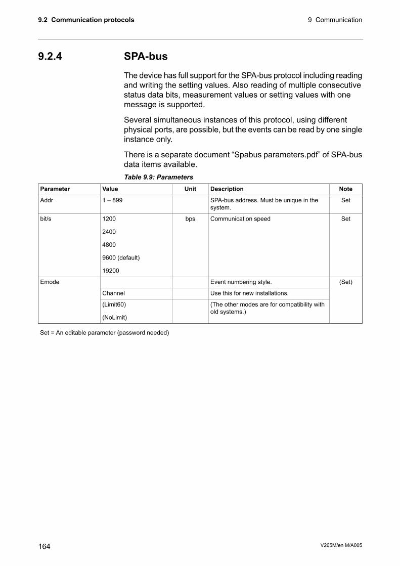
9.2.4 SPA-busThe device has full support for the SPA-bus protocol including readingand writing the setting values. Also reading of multiple consecutivestatus data bits, measurement values or setting values with onemessage is supported.
Several simultaneous instances of this protocol, using differentphysical ports, are possible, but the events can be read by one singleinstance only.
There is a separate document “Spabus parameters.pdf” of SPA-busdata items available.Table 9.9: Parameters
NoteDescriptionUnitValueParameter
SetSPA-bus address. Must be unique in thesystem.
1 – 899Addr
SetCommunication speedbps1200
2400
4800
9600 (default)
19200
bit/s
(Set)Event numbering style.Emode
Use this for new installations.Channel
(The other modes are for compatibility withold systems.)
(Limit60)
(NoLimit)
Set = An editable parameter (password needed)
V265M/en M/A005164
9 Communication9.2 Communication protocols

9.2.5 IEC 60870-5-103The IEC standard 60870-5-103 "Companion standard for theinformative interface of protection equipment" provides standardizedcommunication interface to a primary system (master system).
The unbalanced transmission mode of the protocol is used, and thedevice functions as a secondary station (slave) in the communication.Data is transferred to the primary system using "data acquisition bypolling"-principle.
The IEC functionality includes application functions:
• station initialization
• general interrogation
• clock synchronization and
• command transmission.
It is not possible to transfer parameter data or disturbance recordingsvia the IEC 103 protocol interface.
The following ASDU (Application Service Data Unit) types will beused in communication from the device:
• ASDU 1: time tagged message
• ASDU 3: Measurands I
• ASDU 5: Identification message
• ASDU 6: Time synchronization and
• ASDU 8: Termination of general interrogation.
The device will accept:
• ASDU 6: Time synchronization
• ASDU 7: Initiation of general interrogation and
• ASDU 20: General command.
The data in a message frame is identified by:
• type identification
• function type and
• information number.
These are fixed for data items in the compatible range of the protocol,for example, the trip of I> function is identified by: type identification= 1, function type = 160 and information number = 90. "Private range"function types are used for such data items, which are not definedby the standard (e.g. the status of the digital inputs and the controlof the objects).
165V265M/en M/A005
9.2 Communication protocols9 Communication

The function type and information number used in private rangemessages is configurable. This enables flexible interfacing to differentmaster systems.
For more information on IEC 60870-5-103 in VAMP devices refer tothe “IEC103 Interoperability List” document.Table 9.10: Parameters
NoteDescriptionUnitValueParameter
SetAn unique address within the system1 – 254Addr
SetCommunication speedbps9600
19200
bit/s
SetMinimum measurement response intervalms200 – 10000MeasInt
SetASDU6 response time modeSync
Sync+Proc
Msg
Msg+Proc
SyncRe
Set = An editable parameter (password needed)
Table 9.11: Parameters for disturbance record readingNoteDescriptionUnitValueParameter
SetEnable record info messageOnASDU23
Off
SetRecord samples in one message1 – 25Smpls/msg
SetRecord reading timeouts10 – 10000Timeout
Fault identifier number for IEC-103. Starts +trips of all stages.
Fault
Position of read pointerTagPos
Active channelChn
Channel read positionChnPos
Fault numbering
Total number of faultsFaults
Fault burst identifier numberGridFlts
SetTime window to classify faults together to thesame burst.
Grid
Set = An editable parameter (password needed)
V265M/en M/A005166
9 Communication9.2 Communication protocols

9.2.6 DNP 3.0The relay supports communication using DNP 3.0 protocol. Thefollowing DNP 3.0 data types are supported:
• binary input
• binary input change
• double-bit input
• binary output
• analog input
• counters
Additional information can be obtained from the “DNP 3.0 DeviceProfile Document” and “DNP 3.0 Parameters.pdf”. DNP 3.0communication is activated via menu selection. RS-485 interface isoften used but also RS-232 and fibre optic interfaces are possible.Table 9.12: Parameters
SetDescriptionUnitValueParameter
SetCommunication speedbps4800
9600 (default)
19200
38400
bit/s
SetParityNone (default)
Even
Odd
Parity
SetAn unique address for the device within thesystem
1 – 65519SlvAddr
SetAddress of master1 – 65519
255 = default
MstrAddr
SetLink layer confirmation timeoutms0 – 65535LLTout
SetLink layer retry count1 – 255
1 = default
LLRetry
SetApplication layer confirmation timeoutms0 – 65535
5000 = default
APLTout
SetApplication layer confirmation modeEvOnly (default)
All
CnfMode
SetDouble-bit input supportNo (default)
Yes
DBISup
SetClock synchronization request interval.
0 = only at boot
s0 – 65535SyncMode
Set = An editable parameter (password needed)
167V265M/en M/A005
9.2 Communication protocols9 Communication

9.2.7 IEC 60870-5-101The IEC 60870-5-101 standard is derived from the IEC 60870-5protocol standard definition. In VAMP devices, IEC 60870-5-101communication protocol is available via menu selection. The VAMPunit works as a controlled outstation (slave) unit in unbalancedmode.
Supported application functions include process data transmission,event transmission, command transmission, general interrogation,clock synchronization, transmission of integrated totals, andacquisition of transmission delay.
For more information on IEC 60870-5-101 in VAMP devices, referto the “IEC 101 Profile checklist & datalist.pdf” document.Table 9.13: Parameters
NoteDescriptionUnitValueParameter
SetBitrate used for serial communication.bps1200bit/s
2400
4800
9600
SetParity used for serial communicationNoneParity
Even
Odd
SetLink layer address1 – 65534LLAddr
SetSize of Link layer addressBytes1 – 2LLAddrSize
SetASDU address1 – 65534ALAddr
SetSize of ASDU addressBytes1 – 2ALAddrSize
SetInformation object address size. (3-octetaddresses are created from 2-octet ad-dresses by adding MSB with value 0.)
Bytes2 – 3IOAddrSize
Cause of transmission sizeBytes1COTsize
SetThe parameter determines time tag format:3-octet time tag or 7-octet time tag.
Short
Full
TTFormat
SetThe parameter determines measurementdata format: normalized value or scaledvalue.
Scaled
Normalized
MeasFormat
SetDead-band calculation enable flagNoDbandEna
Yes
SetDead-band calculation intervalms100 – 10000DbandCy
Set = An editable parameter (password needed)
V265M/en M/A005168
9 Communication9.2 Communication protocols

9.2.8 External I/O (Modbus RTU master)External Modbus I/O devices can be connected to the relay usingthis protocol. (See Chapter 11.6.2 External input / output modulemodule for more information).
9.2.9 IEC 61850The relay supports communication using IEC 61850 protocol withnative implementation. IEC 61850 protocol is available with theoptional inbuilt Ethernet port. The protocol can be used to read /write static data from the relay or to receive events and to receive /send GOOSE messages to other relays.
IEC 61850 server interface is capable of
• Configurable datamodel: selection of logical nodes correspondingto active application functions
• Configurable pre-defined data sets
• Supported dynamic data sets created by clients
• Supported reporting function with buffered and unbuffered ReportControl Blocks
• Sending analogue values over GOOSE
• Supported control modes:
- direct with normal security
- direct with enhanced security
- select before operation with normal security
- select before operation with enhanced security
• Supported horizontal communication with GOOSE: configurableGOOSE publisher data sets, configurable filters for GOOSEsubscriber inputs, GOOSE inputs available in the applicationlogic matrix
Additional information can be obtained from the separate documents“IEC 61850 conformance statement.pdf”, “IEC 61850 Protocoldata.pdf” and “Configuration of IEC 61850 interface.pdf”.
169V265M/en M/A005
9.2 Communication protocols9 Communication

9.2.10 EtherNet/IPThe device supports communication using EtherNet/IP protocol whichis a part of CIP (Common Industrial Protocol) family. EtherNet/IPprotocol is available with the optional inbuilt Ethernet port. Theprotocol can be used to read / write data from the device usingrequest / response communication or via cyclic messagestransporting data assigned to assemblies (sets of data).
For more detailed information and parameter lists for EtherNet/IP,refer to a separate application note “Application NoteEtherNet/IP.pdf”.
For the complete data model of EtherNet/IP, refer to the document“Application Note DeviceNet and EtherNetIP Data Model.pdf”.
9.2.11 FTP serverThe FTP server is available on VAMP IEDs equipped with an inbuiltor optional Ethernet card.
The server enables downloading of the following files from an IED:
• Disturbance recordings.
• The MasterICD and MasterICDEd2 files.
TheMasterICD andMasterICDEd2 files are VAMP-specific referencefiles that can be used for offline IEC61850 configuration.
The inbuilt FTP client in Microsoft Windows or any other compatibleFTP client may be used to download files from the device.
NoteDescriptionUnitValueParameter
SetEnable or disable the FTP server.YesEnable FTP server
No
SetRequired to access the FTP server with an FTPclient. Default is “config”. The user name is al-ways “vamp”.
Max 33 charactersFTP password
SetThe maximum speed at which the FTP serverwill transfer data.
KB/s1 – 10FTP max speed
V265M/en M/A005170
9 Communication9.2 Communication protocols

9.2.12 DeviceNetThe device supports communication using DeviceNet protocol whichis a part of CIP (Common Industrial Protocol) family. DeviceNetprotocol is available with the optional external VSE009 module. Theprotocol can be used to read / write data from the device usingrequest / response communication or via cyclic messagestransporting data assigned to assemblies (sets of data).
For more detailed information about DeviceNet, refer to a separateapplication note “Application Note DeviceNet.pdf”.
For the complete data model of DeviceNet, refer to the document“Application Note DeviceNet and EtherNetIP Data Model.pdf”.
171V265M/en M/A005
9.2 Communication protocols9 Communication

10 Applications
10.1 Restricted earth fault protectionRestricted earth fault (REF) protection is a sensitive way to protecta zone between two measuring points against earth faults. SeeFigure 10.1.
Figure 10.1: Principle of restricted earth fault protection. The CT secondaries arewired to cancel each other's currents during through faults and to drive all to therelay when the fault is inside the protected zone. (Saturation of the CTs makesthe situation a little more complicated than that.) The stabilizing resistor RSguarantees that the relay will not trip during a through fault. The VDR is used toprotect the CTs and the wiring by limiting the voltage VS during heavy inside faults.
When there is a fault outside the protected zone the CT secondarieswill cancel each other's currents. This is partly true even if both oronly one of the CTs saturates, because the impedance of a saturatedCT secondary will collapse to near zero. The non-zero wiringimpedance and CT impedance will however cause a voltage VS, butthe resistor RS will prevent the relay from tripping. RS is called thestabilizing resistor.
During an inside fault the secondary currents of the two CTs haveno other way to go than the relay. The relay will trip when the currentI = VS / RS exceeds the setting IS of the relay. The voltage dependentresistor (VDR, varistor, METROSIL) is used to protect the CTs andwiring by limiting the voltage VS during heavy inside faults.
The resistance of the secondary loop connecting the CTs togethershould be as low as possible.
V265M/en M/A005172
10 Applications
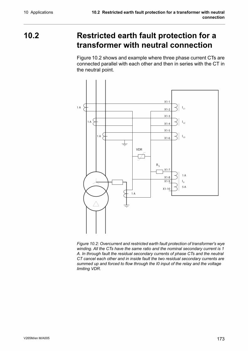
10.2 Restricted earth fault protection for atransformer with neutral connectionFigure 10.2 shows and example where three phase current CTs areconnected parallel with each other and then in series with the CT inthe neutral point.
RS
VDR
IL1
IL2
IL3
1 A
1 A
1 A
1 A
1 A
5 A
I0
X1-1
X1-2
X1-3
X1-4
X1-5
X1-6
X1-7
X1-8
X1-9
X1-10
Figure 10.2: Overcurrent and restricted earth fault protection of transformer's wyewinding. All the CTs have the same ratio and the nominal secondary current is 1A. In through fault the residual secondary currents of phase CTs and the neutralCT cancel each other and in inside fault the two residual secondary currents aresummed up and forced to flow through the I0 input of the relay and the voltagelimiting VDR.
173V265M/en M/A005
10.2 Restricted earth fault protection for a transformer with neutralconnection
10 Applications
10.2.1 CT RequirementsAny difference between the CTs will give a misleading residualcurrent signal to the relay. Especially during heavy through faults(i.e. the fault is outside the protected zone) the dissimilar saturationof the CTs should not yield to a REF trip. On the other hand a veryhigh fault current causing an unselective earth fault start or trip isnot a fatal error.
Class X CT
In restricted earth fault protection the high and low side CTs shouldgive similar responses even for high over currents.
Class X CTs will fulfil this requirement. Their performance is definedin terms of a knee-point voltage (VKP), the magnetizing current atthe knee point voltage and the resistance of the secondary windingat +75°C.
Knee point voltage (VKP) is the secondary voltage at which a 50 %increase of primary current is needed to increase the secondaryvoltage by 10 %.
V265M/en M/A005174
10 Applications10.2 Restricted earth fault protection for a transformer with neutralconnection

10.3 Calculating the stabilizing resistance RS,VDR value and actual sensitivity
10.3.1 Value of stabilizing resistor RSThe voltage VS (Figure 10.1) is:
Equation 10.1:
WCT
PRIM
SEC
MAXTSRR
CT
CTIV +=
IMAXT = Maximum through fault current not to cause an REF trip *
CTSEC = Nominal secondary current of the CT
CTPRI = Nominal primary current of the CT
RCT = Resistance of CT secondary.
RW = Total resistance of wiring, connections etc.
The CT should be of class X (see Chapter 10.2.1 CT Requirements)and the knee point voltage should be twice the calculated VS.
The stabilizing resistor RS is calculated as:
Equation 10.2:
R
V
IS
S
Set
=
ISET = Setting value of the relay as secondary value.
-
* Selecting a low value helps to achieve more sensitivity and helpsto avoid the usage of a voltage limiting VDR. An unselective earthfault pick-up/trip is not always a problem if a fast overcurrent stagewill clear the fault anyway.
175V265M/en M/A005
10.3 Calculating the stabilizing resistance RS, VDR value and actualsensitivity
10 Applications

10.3.2 Voltage limitDuring heavy inside faults the voltage in the secondary circuit mayrise to several kilovolts depending on the fault currents, CT propertiesand the stabilizing resistor RS. If the secondary voltage would exceed2 kV it should be limited using a voltage dependent resistor (VDR).
The peak voltage according a linear CT model is:
Equation 10.3:
SWCT
PRIM
SEC
MAXFpRRB
CT
CTIV ++=
Maximum fault current when the fault is inside theprotected zone
=IMAXF
Nominal secondary current of the CT=CTSECNominal primary current of the CT=CTPRIResistance of CT secondary.=RCT
Total resistance of wiring, connections, relay input etc.=RW
Stabilizing resistor according Equation 10.2.=RS
The peak voltage of a saturating CT can be approximated using P.Mathews' formula:
Equation 10.4:
KPPKPspVVVV −= 22
Knee point voltage of the CT. The secondary voltage atwhich a 50 % increase of primary current is needed toincrease the secondary voltage by 10%.
=VKP
Peak voltage according linear model of a CT=VP
This approximating formula does not hold for an open circuit conditionand is inaccurate for very high burden resistances.
V265M/en M/A005176
10 Applications10.3 Calculating the stabilizing resistance RS, VDR value and actualsensitivity

10.3.3 Actual operating sensitivityThe differential scheme will multiply the fault current by two thusincreasing the sensitivity from the actual setting. The quiescentcurrent of the possible VDR will decrease the sensitivity from theactual setting value.
10.3.4 ExampleCT = 2000/1 A
VKP = 100 V
IMAXT = 16 kA = 8 x IN
IREF = 5 % = 50 mA, setting value scaled to secondary level
RCT = 6 Ω
RW = 0.4 Ω
IMAXF = 25 kA
Maximum secondary voltage during a through fault (Equation 10.1):
V 2.514.062000
116000 −+=
SV
Conclusion: The knee point voltage of 100 V is acceptable beingabout twice the VS.
Serial resistance for the relay input (Equation 10.2):
RS= = ≈
512
0 051024 1000
.
. Ω Ω
Maximum peak voltage during inside fault using a linear model forCT (Equation 10.3):
kV 6.12)10004.06(2000
125000 =++=
pV
Approximation of peak voltage during inside fault using a non-linearmodel for a saturating CT (Equation 10.4): kV 2.3)10012600(10022 =−⋅=spV
This is a too high value and a VDR must be used to reduce thevoltage below 3 kV.
A zinc oxide varistor (i.e. VDR, METROSIL) of 1 kV will limit thevoltage. Using a 400 J model allows two 20 VA CTs feeding tentimes their nominal power during one second before the energycapacity of the varistor is exceeded.
177V265M/en M/A005
10.3 Calculating the stabilizing resistance RS, VDR value and actualsensitivity
10 Applications

10.4 Current Transformer SelectionIron core current transformers (CT) are accurate in amplitude andphase when used near their nominal values. At very low and at veryhigh currents they are far from ideal. For over-current and differentialprotection, the actual performance of CTs at high currents must bechecked to ensure correct function of the protection relay.
10.4.1 CT classification according IEC 60044-1, 1996
m m
p s
s
s
w
Figure 10.3: A CT equivalent circuit. Lm is the saturable magnetisation inductance,L is secondary of an ideal current transformer, RCT is resistance of the CTsecond¬ary winding, RW is resistance of wiring and RL is the burden i.e. theprotection relay.
Composite error εCComposite error is the difference between the ideal secondary currentand the actual secondary current under steady-state conditions. Itincludes amplitude and phase errors and also the effects of anypossible harmonics in the exciting current.
Equation 10.5:
%100
)(1 2
0⋅
−
=
∫
P
T
PSN
C
I
dtiiKT
ε
T = Cycle time
KN = Rated transformation ratio INPrimary / INsecondary
iS = Instantaneous secondary current
iP = Instantaneous primary current
IP = Rms value of primary current
V265M/en M/A005178
10 Applications10.4 Current Transformer Selection

NOTE: All current based protection functions of VAMP relays, except arcprotection, thermal protection and 2nd harmonic blocking functions,are using the fundamental frequency component of the measuredcurrent. The IEC formula includes an RMS value of the current. Thatis why the composite error defined by IEC 60044-1 is not ideal forVAMP relays. However the difference is not big enough to preventrough estimation.
Standard accuracy classes
At rated frequency and with rated burden connected, the amplitudeerror, phase error and composite error of a CT shall not exceed thevalues given in the following table.
Composite error εCat rated accuracylimit primary cur-rent (%)
Phasedisplacementat rated primarycurrent (°)
Amplitude error atrated primary cur-rent (%)
Accuracy class
5±1±15P
10-±310P
Marking:
The accuracy class of a CT is written after the rated power.
E.g. 10 VA 5P10, 15 VA 10P10, 30 VA 5P20
Accuracy limit current IALCurrent transformers for protectionmust retain a reasonable accuracyup to the largest relevant fault current. Rated accuracy limit currentis the value of primary current up to which the CT will comply withthe requirements for composite error εC.
Accuracy limit factor kALFThe ratio of the accuracy limit current to the rated primary current.
Equation 10.6:
N
AL
ALF
I
IK =
The standard accuracy limit factors are 5, 10, 15, 20 and 30.
Marking:
Accuracy limit factor is written after the accuracy class.
E.g. 0 VA 5P10, 15 VA 10P10, 30 VA 5P20.
The actual accuracy limit factor kA depends on the actual burden.
179V265M/en M/A005
10.4 Current Transformer Selection10 Applications

Equation 10.7:
Ai
Ni
ALFA
SS
SSkk
+
+=
Accuracy limit factor at rated current and rated burdenkALF =
Internal secondary burden. (Winding resistance RCT inFigure 10.3)
Si =
Rated burdenSN =
Actual burden including wiring and the load.SA =
Figure 10.4: This figure of Equation 10.4.1 3 shows that it is essential to know thewinding resistance RCT of the CT if the load is much less than the nominal. A 10VA 5P10 CT with 25% load gives actual ALF values from 15 - 30 when the windingresistance varies from 0.5 Ω to 0.05 Ω.
V265M/en M/A005180
10 Applications10.4 Current Transformer Selection

10.4.2 CT Requirement for ProtectionWhen the through current equals and exceeds kA x IN there may beenough secondary differential current to trip a relay although thereis no in zone fault. This is because the CTs are unique and they donot behave equally when approaching saturation.
To avoid false trips caused by heavy through faults the actualaccuracy limit factor kA of the CTs should exceed the relative settingISET of the non-stabilized differential stage.
Equation 10.8:
NCT
NTra
SET
A
I
IIck ⋅⋅>
Safety factorc =
Relative setting of the non-stabilized differential currentstage
ISET =
Rated current of the transformer (primary side or secondaryside)
INTra =
Rated primary current of the CT (primary side or secondaryside)
INCT =
Using slightly smaller safety factor than indicated in the table willincrease the setting inaccuracy.
Safety factor cProtection application
2Overcurrent
3Earth-fault, cable transformer
6Earth-fault overcurrent, sum of three phase currents *
3Transformer differential, Δ-winding or unearthed Y-winding
4Transformer differential, earthed Y-winding
3Generator differential
* Sensitive earth-fault current settings, < 5% x IN, should be avoidedin this configuration because a set of three CTs are not exactly similarand will produce some secondary residual current even though thereis no residual current in the primary side.
Formula to solve needed CT power SN
By replacing the complex power termswith corresponding resistancesin Equation 10.7, we get
181V265M/en M/A005
10.4 Current Transformer Selection10 Applications

Equation 10.9:
LWCT
NCT
ALFA
RRR
RRkk
++
+=
where the nominal burden resistance is
Equation 10.10:
2
secNCT
N
N
I
SR =
RCT = Winding resistance (See Figure 10.3)
RW = Wiring resistance (from CT to the relay and back)
RL = Resistance of the protection relay input
SN = Nominal burden of the CT
INCTsec = Nominal secondary current of the CT
By solving SN and substituting kA according Equation 10.9, we get
Equation 10.11:
( )2
secNCTCTLWCT
NCTALF
NTraSET
NIRRRR
Ik
IcIS
−++>
10.4.3 ExampleTransformer:
16 MVA YNd11 Zk = 10%
110 kV / 21 kV (84 A / 440 A)
CT’s on HW side:
100/5 5P10
Winding resistance RCT = 0.07 Ω
(RCT depends on the CT type, INCT and power rating. Let's say thatthe selected CT type, 100 A and an initial guess of 15 VA yields to0.07 Ω.)
Safety factor c = 4.
(Transformer differential, earthed Y.)
V265M/en M/A005182
10 Applications10.4 Current Transformer Selection
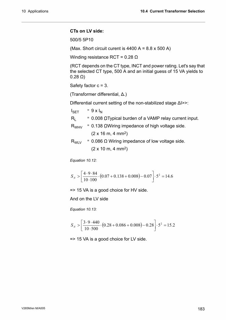
CTs on LV side:
500/5 5P10
(Max. Short circuit curent is 4400 A = 8.8 x 500 A)
Winding resistance RCT = 0.28 Ω
(RCT depends on the CT type, INCT and power rating. Let's say thatthe selected CT type, 500 A and an initial guess of 15 VA yields to0.28 Ω)
Safety factor c = 3.
(Transformer differential, Δ.)
Differential current setting of the non-stabilized stage ΔI>>:
9 x IN=ISET0.008 ΩTypical burden of a VAMP relay current input.=RL
0.138 ΩWiring impedance of high voltage side.=RWHV
(2 x 16 m, 4 mm2)
0.086 Ω Wiring impedance of low voltage side.=RWLV
(2 x 10 m, 4 mm2)
Equation 10.12:
( ) 6.14507.0008.0138.007.010010
8494 2=⋅
−++⋅
⋅
⋅⋅>
NS
=> 15 VA is a good choice for HV side.
And on the LV side
Equation 10.13:
( ) 2.15528.0008.0086.028.050010
44093 2=⋅
−++⋅
⋅
⋅⋅>
NS
=> 15 VA is a good choice for LV side.
183V265M/en M/A005
10.4 Current Transformer Selection10 Applications

10.5 Application example of differentialprotection using VAMP 265M
VAMP 265Remote
Local
Front
A1
X3:10
X3:9
X3:11
T2
T1
X3:13
X3:14
X3:15
X3:12
A2
A3
A4
A5
IF
X2:13
X2:14
X2:15
X2:10
X2:11
X2:12
X2:7
X2:8
X2:6
X2:5
X2:16
X2:17
X2:18
X5
X4
IL1
IL2
IL3
I 01
I 02
DI
X1:1
X1:2
X1:3
X1:4
X1:5
X1:6
X1:11
X1:12
X1:13
X1:16
X1:7
X1:8
X1:9
X1:10
X1:14
X1:15
X3:17
X3:18
I’L1
I’L2
I’L3
~
L1 L2 L3
++
X3:1+48VDC
X3:2DI1
X3:3DI2
X3:4DI3
X3:5DI4
X3:6DI5
X3:7DI6
X6:1
X6:2
X6:3
X6:4
X6:5
X6:6
X6:7
2
P1
P2
S1 S2
BI/O
L>
Arcoption
P1
P2
S1
S2
M
Figure 10.5: Differential protection of a motor using VAMP 265M.
Settings:Yy0ConnGrp
OFFIoCmps
OFFI’oCmps
Generator nominal voltageUn
Generator nominal voltageU’n
V265M/en M/A005184
10 Applications10.5 Application example of differential protection using VAMP 265M

10.6 Trip circuit supervisionTrip circuit supervision is used to ensure that the wiring from theprotective device to a circuit-breaker is in order. This circuit is unusedmost of the time, but when a protection device detects a fault in thenetwork, it is too late to notice that the circuit-breaker cannot betripped because of a broken trip circuitry.
The digital inputs of the device can be used for trip circuit monitoring.The dry digital inputs are most suitable for trip circuit supervision.The first six digital inputs of VAMP 200 series relays are not dry andan auxiliary miniature relay is needed, if these inputs are used fortrip circuit supervision.
Also the closing circuit can be supervised, using the same principle.
In many applications the optimum digital inputs for trip circuitsupervision are the optional inputs DI19 and DI20. They don't sharetheir terminals with any other digital inputs.
10.6.1 Trip circuit supervision with one digital inputThe benefits of this scheme is that only one digital inputs is neededand no extra wiring from the relay to the circuit breaker (CB) isneeded. Also supervising a 24 Vdc trip circuit is possible.
The drawback is that an external resistor is needed to supervise thetrip circuit on both CB positions. If supervising during the closedposition only is enough, the resistor is not needed.
• The digital input is connected parallel with the trip contacts(Figure 10.6).
• The digital input is configured as Normal Closed (NC).
• The digital input delay is configured longer than maximum faulttime to inhibit any superfluous trip circuit fault alarm when thetrip contact is closed.
• The digital input is connected to a relay in the output matrix givingout any trip circuit alarm.
• The trip relay should be configured as non-latched. Otherwise,a superfluous trip circuit fault alarm will follow after the trip contactoperates, and the relay remains closed because of latching.
• By utilizing an auxiliary contact of the CB for the external resistor,also the auxiliary contact in the trip circuit can be supervised.
• When using the dry digital inputs DI7 –, using the other inputsof the same group, sharing a common terminal, is limited.
• When using the wet digital inputs DI1 – DI6, an auxiliary relay isneeded.
185V265M/en M/A005
10.6 Trip circuit supervision10 Applications

Using optional DI19 or DI20
NOTE: In the VAMP 265M, only the optional digital inputs DI19 and DI20are dry (see the ordering code for this option).
52b 52a
TCS1DIclosed_1
Figure 10.6: Trip circuit supervision using a single digital input and an external resistorR. The circuit-breaker is in the closed position. The supervised circuitry in this CBposition is double-lined. The digital input is in active state when the trip circuit iscomplete. This is applicable for dry inputs DI19 – DI20.
NOTE: The need for the external resistor R depends on the application andcircuit breaker manufacturer's specifications.
V265M/en M/A005186
10 Applications10.6 Trip circuit supervision

52a
TCS1DIclosed_2
Figure 10.7: Alternative connection without using circuit breaker 52b auxiliary contacts.Trip circuit supervision using a single digital input and an external resistor R. Thecircuit-breaker is in the closed position. The supervised circuitry in this CB positionis double-lined. The digital input is in active state when the trip circuit is complete.This is applicable for dry inputs DI19 – DI20.
187V265M/en M/A005
10.6 Trip circuit supervision10 Applications

52b 52a
TCS1DIopen_1
Figure 10.8: Trip circuit supervision using a single dry digital input, when the circuitbreaker is in open position.
V265M/en M/A005188
10 Applications10.6 Trip circuit supervision

52a
TCS1DIopen_2
Figure 10.9: Alternative connection without using circuit breaker 52b auxiliary contacts.Trip circuit supervision using a single dry digital input, when the circuit breaker is inopen position.
Figure 10.10: An example of digital input DI19 configuration for trip circuitsupervision with one dry digital input.
189V265M/en M/A005
10.6 Trip circuit supervision10 Applications

Figure 10.11: An example of output matrix configuration for trip circuit supervisionwith one digital input.
Example of dimensioning the external resistor R:110 Vdc - 20% + 10%, Auxiliary voltage with toleranceUAUX =
18 Vdc, Threshold voltage of the digital inputUDI =
3 mA, Typical current needed to activate the digitalinput including a 1 mA safety margin.
IDI =
50 W, Rated power of the open coil of the circuitbreaker. If this value is not known, 0 Ω can be usedfor the RCOIL.
PCOIL =
UAUX - 20 % = 88 VUMIN =
UAUX + 10 % = 121 VUMAX =
U2AUX / PCOIL = 242 Ω.RCOIL =
The external resistance value is calculated using Equation 10.14.
Equation 10.14:
DI
CoilDIDIMIN
I
RIUUR
⋅−−=
R = (88 – 18 – 0.003*242)/0.003 = 23.1 kΩ
(In practice the coil resistance has no effect.)
By selecting the next smaller standard size we get 22 kΩ.
The power rating for the external resistor is estimated usingEquation 10.15 and Equation 10.16. The Equation 10.15 is for theCB open situation including a 100 % safety margin to limit themaximum temperature of the resistor.
Equation 10.15:
RIPDI⋅⋅=
22
P = 2*0.003^2 x 22000 = 0.40 W
Select the next bigger standard size, for example 0.5 W.
V265M/en M/A005190
10 Applications10.6 Trip circuit supervision

When the trip contacts are still closed and the CB is already open,the resistor has to withstand much higher power (Equation 10.16)for this short time.
Equation 10.16:
R
UP
MAX
2
=
P = 121^2 / 22000 = 0.67 W
A 0.5 W resistor will be enough for this short time peak power, too.However, if the trip relay is closed for longer time than a few seconds,a 1 W resistor should be used.
Using any of the non-dry digital inputs DI1 – DI6
In this scheme an auxiliary relay is needed to connect the wet digitalinput to the trip circuit (Figure 10.12). The rated coil voltage of theauxiliary relay is selected according the rated auxiliary voltage usedin the trip circuit. The operating voltage range of the relay should beas wide as possible to cover the tolerance of the auxiliary voltage.
In this application using the other wet inputs for other purposes isnot limited unlike, when using the dry inputs.
191V265M/en M/A005
10.6 Trip circuit supervision10 Applications

52b 52a
Figure 10.12: Trip circuit supervision using one of the VAMP 200 series internallywetted digital input (DI1 – DI6) and auxiliary relay K1 and an external resistor R. Thecircuit-breaker is in the closed position. The supervised circuitry in this CB positionis double-lined. The digital input is in active state when the trip circuit is complete.
Figure 10.13: An example of digital input DI1 configuration for trip circuit supervisionwith one wet digital input.
V265M/en M/A005192
10 Applications10.6 Trip circuit supervision
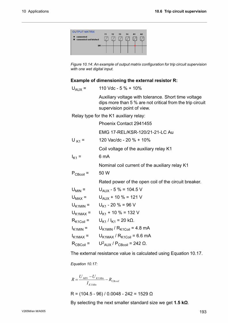
Figure 10.14: An example of output matrix configuration for trip circuit supervisionwith one wet digital input.
Example of dimensioning the external resistor R:110 Vdc - 5 % + 10%UAUX =
Auxiliary voltage with tolerance. Short time voltagedips more than 5 % are not critical from the trip circuitsupervision point of view.
Relay type for the K1 auxiliary relay:
Phoenix Contact 2941455
EMG 17-REL/KSR-120/21-21-LC Au
120 Vac/dc - 20 % + 10%U K1 =
Coil voltage of the auxiliary relay K1
6 mAIK1 =
Nominal coil current of the auxiliary relay K1
50 WPCBcoil =
Rated power of the open coil of the circuit breaker.
UAUX - 5 % = 104.5 VUMIN =
UAUX + 10 % = 121 VUMAX =
UK1 - 20 % = 96 VUK1MIN =
UK1 + 10 % = 132 VUK1MAX =
UK1 / IK1 = 20 kΩ.RK1Coil =
UK1MIN / RK1Coil = 4.8 mAIK1MIN =
UK1MAX / RK1Coil = 6.6 mAIK1MAX =
U2AUX / PCBcoil = 242 Ω.RCBCoil =
The external resistance value is calculated using Equation 10.17.
Equation 10.17:
CBcoil
MinK
MinKMINR
I
UUR −
−=
1
1
R = (104.5 - 96) / 0.0048 - 242 = 1529 Ω
By selecting the next smaller standard size we get 1.5 kΩ.
193V265M/en M/A005
10.6 Trip circuit supervision10 Applications

The power rating for the external resistor is calculated usingEquation 10.18. This equation includes a 100 % safety margin tolimit the maximum temperature of the resistor, because modernresistors are extremely hot at their rated maximum power.
Equation 10.18:
RIPMaxK
⋅⋅=2
12
P = 2*0.0066^2 x 1500 = 0.13 W
Select the next bigger standard size, for example 0.5 W.
When the trip contacts are still closed and the CB is already open,the resistor has to withstand much higher power (Equation 10.16)for this short time.
P = 121^2 / 1500 = 9.8 W
A 1 W resistor should be selected to withstand this short time peakpower. However, if the trip relay can be closed for longer time thana few seconds, a 20 W resistor should be used.
10.6.2 Trip circuit supervision with DI19 and DI20The benefits of this scheme is that no external resistor is needed.
The drawbacks are, that two digital inputs from two separate groupsare needed and two extra wires from the relay to the CB compartmentis needed. Additionally the minimum allowed auxiliary voltage is 48Vdc, which is more than twice the threshold voltage of the dry digitalinput, because when the CB is in open position, the two digital inputsare in series.
• The first digital input is connected parallel with the auxiliarycontact of the open coil of the circuit breaker.
• Another auxiliary contact is connected in series with the circuitryof the first digital input. This makes it possible to supervise alsothe auxiliary contact in the trip circuit.
• The second digital input is connected in parallel with the tripcontacts.
• Both inputs are configured as normal closed (NC).
• The user’s programmable logic is used to combine the digitalinput signals with an AND port. The delay is configured longerthan maximum fault time to inhibit any superfluous trip circuitfault alarm when the trip contact is closed.
• The output from the logic is connected to a relay in the outputmatrix giving out any trip circuit alarm.
V265M/en M/A005194
10 Applications10.6 Trip circuit supervision

• The trip relay should be configured as non-latched. Otherwise,a superfluous trip circuit fault alarm will follow after the trip contactoperates, and the relay remains closed because of latching.
• Both digital inputs must have their own common potential.Using the other digital inputs in the same group as the upper DIin the Figure 10.15 is not possible in most applications. Usingthe other digital inputs in the same group as the lower DI in theFigure 10.15 is limited, because the whole group will be tied tothe auxiliary voltage VAUX.
NOTE: In many applications the optimum digital inputs for trip circuitsupervision are the optional inputs DI19 and DI20 because they don'tshare their terminals with any other digital inputs.
52b 52a
Figure 10.15: Trip circuit supervision with two digital inputs. The CB is closed. Thesupervised circuitry in this CB position is double-lined. The digital input is in activestate when the trip circuit is complete. This is applicable for dry inputs DI7 – D20 only.
195V265M/en M/A005
10.6 Trip circuit supervision10 Applications

52b 52a
Figure 10.16: Trip circuit supervision with two digital inputs. The CB is in the openposition. The two digital inputs are now in series.
V265M/en M/A005196
10 Applications10.6 Trip circuit supervision

Figure 10.17: An example of digital input configuration for trip circuit supervisionwith two dry digital inputs DI19 and DI20
NOTE: Only inputs DI19 and DI20 can be used for this function in VAMP265M.
Figure 10.18: An example of logic configuration for trip circuit supervision with twodry digital inputs DI19 and DI20.
NOTE: Only inputs DI19 and DI20 can be used for this function in VAMP265M.
Figure 10.19: An example of output matrix configuration for trip circuit supervisionwith two digital inputs.
197V265M/en M/A005
10.6 Trip circuit supervision10 Applications

11 Connections
11.1 Rear panel
1
2
3
4
5
6
7
8
9
10
11
12
13
14
15
16
17
18
1
2
3
4
5
6
7
8
9
10
11
12
13
14
15
16
17
18
1
3
5
7
9
11
13
15
17
19
2
4
6
8
10
12
14
16
18
20
X3 X6 X1
VY
X0
60
A
VAMP265rearPanel
40..265V
AC
/DC
LO
CA
L(R
S 2
32)
RE
MO
TE
(TT
L)
Digitalinputs
48V
DI1
DI2
DI3
DI4
DI5
DI6
A1
A5
A4
A3
A2
IF
T1
Uaux
T2
I´
I
I´
I
I
I I
I
I I
I I
I´ I´
I´ I´
L1L1
L3
0101
0202
L3
L2L2
L1L1
L2L2
L3L3
1
2
3
4
5
6
7
X5
X4
X2
Figure 11.1: Connections on the rear panel of the VAMP 265
VAMP 265M is connected to the protected object through thefollowing measuring and control connections:
• Phase currents IL1, IL2 and IL3 (terminals X1: 1-6)
• Phase currents I’L1, I’L2 and I’L3 (terminals X1: 11-16)
• Earth fault current I01 (terminals X1: 7-8)
• Earth fault current I02 (terminals X1: 9-10)
V265M/en M/A005198
11 Connections

Terminal X1 left side
DescriptionSymbolNo
Phase current IL1 (S1), high voltage side
Phase current IL2 (S1), high voltage side
Phase current IL3 (S1), high voltage side
Residual current Io1 (S1)
Residual current Io2 (S1)
Phase current I’L1 (S1), low voltage side
Phase current I’L2 (S1), low voltage side
Phase current I’L3 (S1), low voltage side
--
--
IL1
IL2
IL3
Io1
Io2
I’L1
I’L2
I’L3
--
--
1
3
5
7
9
11
13
15
17
19
Terminal X1 right side
DescriptionSymbolNo
Phase current L1 (S2), high voltage side
Phase current L2 (S2), high voltage side
Phase current L3 (S2), high voltage side
Residual current Io1 (S2)
Residual current Io2 (S2)
Phase current I’L1 (S2), low voltage side
Phase current I’L2 (S2), low voltage side
Phase current I’L3 (S2), low voltage side
--
--
IL1
IL2
IL3
Io1
Io2
I’L1
I’L2
I’L3
--
--
2
4
6
8
10
12
14
16
18
20
199V265M/en M/A005
11.1 Rear panel11 Connections

Terminal X2 without the analogue output
DescriptionSymbolNo
--
--
--
--
Alarm relay 5
Alarm relay 5
Alarm relay 4
Alarm relay 4
--
Alarm relay 3, common connector
Alarm relay 3, normal closed connector
Alarm relay 3, normal open connector
Alarm relay 2, common connector
Alarm relay 2, normal closed connector
Alarm relay 2, normal open connector
Internal fault relay, common connector
Internal fault relay, normal closed connector
Internal fault relay, normal open connector
--
--
--
--
A5
A5
A4
A4
--
A3 COM
A3 NC
A3 NO
A2 COM
A2 NC
A2 NO
SF COM
SF NC
SF NO
1
2
3
4
5
6
7
8
9
10
11
12
13
14
15
16
17
18
V265M/en M/A005200
11 Connections11.1 Rear panel

Terminal X3
DescriptionSymbolNo
Internal control voltage for digital inputs 1 – 6
Digital input 1
Digital input 2
Digital input 3
Digital input 4
Digital input 5
Digital input 6
--
Alarm relay 1, common connector
Alarm relay 1, normal open connector
Alarm relay 1, normal closed connector
Trip relay 2
Trip relay 2
Trip relay 1
Trip relay 1
--
Auxiliary voltage
Auxiliary voltage
+48V
DI1
DI2
DI3
DI4
DI5
DI6
--
A1 COM
A1 NO
A1 NC
T2
T2
T1
T1
--
Uaux
Uaux
1
2
3
4
5
6
7
8
9
10
11
12
13
14
15
16
17
18
Terminal X6
DescriptionSymbolNo
External arc light input
Arc light output
Common for BI and BO
Arc sensor 1, positive connector *
Arc sensor 1, negative connector *
Arc sensor 2, positive connector *
Arc sensor 2, negative connector *
BI
BO
COM
S1>+
S1>-
S2>+
S2>-
1
2
3
4
5
6
7
*) Arc sensor itself is polarity free
201V265M/en M/A005
11.1 Rear panel11 Connections

Terminal X6 with DI19/DI20 option
DescriptionSymbolNo
Digital input 19
Digital input 19
Digital input 20
Digital input 20
--
Arc sensor 1, positive connector *
Arc sensor 1, negative connector *
DI19
DI19
DI20
DI20
--
S1>+
S1>-
1
2
3
4
5
6
7
*) Arc sensor itself is polarity free
11.2 Auxiliary voltageThe external auxiliary voltage UAUX (standard 40 – 265 V ac/dc oroptional 18 – 36 Vdc) for the pin is connected to the pins X3: 17 –18.
NOTE: When optional 18 – 36 Vdc power module is used the polarity is asfollows: X3:17 negative, X3:18 positive.
11.3 Serial communication connectionThe pin assignments of communication connectors including internalcommunication converters are presented in the following figures andtables.
11.3.1 Front panel connector
RS232 signalPin
Not connected1
Rx in2
Tx out3
DTR out (+8 V)4
GND5
DSR in (activates this port and disables the X4 RS232 port)6
RTS in (Internally connected to pin 8)7
CTS out (Internally connected to pin 7)8
IRIG-B input9
Figure 11.2: Pin numbering of the frontpanel D9S connector
NOTE:DSR must be connected to DTR to activate the front panel connector and disable the rearpanel X4 RS232 port. (The other port in the same X4 connector will not be disabled.)
V265M/en M/A005202
11 Connections11.2 Auxiliary voltage

11.3.2 Rear panel connector X5 (REMOTE)The X5 remote port communication connector options are shown inFigure 11.3. The connector types are listed in Table 11.1.
Without any internal options, X5 is a TTL port for external converters.Some external converters (VSE) are attached directly to the rearpanel and X5. Some other types (VEA, VPA) need variousTTL/RS-232 converter cables. The available accessories are listedin Chapter 14 Order information.
2 & 4-wire galvanically isolated RS-485 (Figure11.4), internal optionsfor fibre optic (Figure 11.5), and Profibus (Figure 11.6) are available.See ordering code in Chapter 14 Order information.Table 11.1: Physical interface and connector types of remote port X5 withvarious options. Serial interface (A) is the default.
Pin usageConnector typeCommunication interfaceOrderCode
1 = reservedD9SSerial interface for external converters only(REMOTE port)
A
2 = TX_out / TTL
3 = RX_in /TTL
4 = RTS out /TTL
7 = GND
9 = +8V out
HFBR-0500Plastic fibre interface (REMOTE port)B
3=RXD/TXD+/PD9SProfibus interface (REMOTE port)C
4=RTS
5= GND
6=+5V
8= RXD/TXD-/N
1= Signal groundscrew terminalRS-485, isolated (REMOTE port)D
2= Reciever -
3= Reciever +
4= Transmitter -
5= Transmitter +
STGlass fibre interface (62.5/125 μm) (REMOTEport)
E
Plastic RxHFBR-0500/STPlastic / glass (62.5/125 μm) fibre interface(REMOTE port)
F
Glass Tx
Glass RxST/HFBR-0500Glass (62.5/125 μm) / plastic fibre interface(REMOTE port)
G
Plastic Tx
203V265M/en M/A005
11.3 Serial communication connection11 Connections
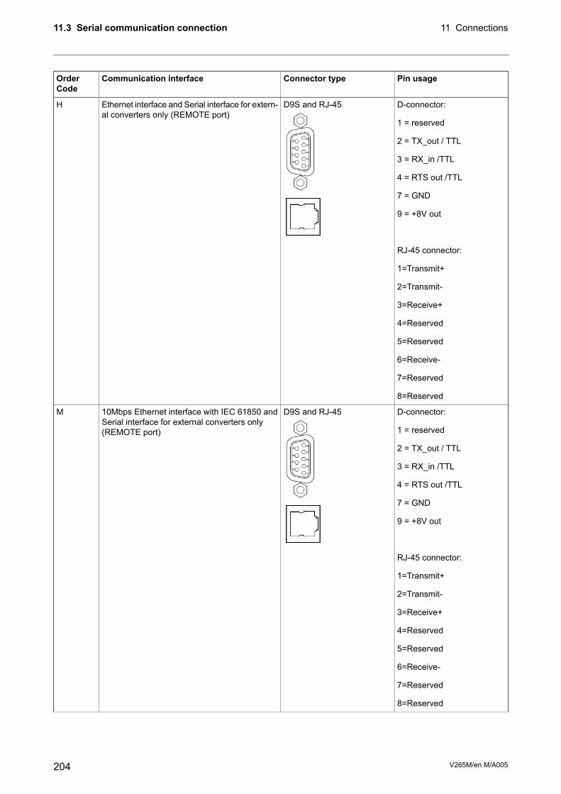
Pin usageConnector typeCommunication interfaceOrderCode
D-connector:D9S and RJ-45Ethernet interface and Serial interface for extern-al converters only (REMOTE port)
H
1 = reserved
2 = TX_out / TTL
3 = RX_in /TTL
4 = RTS out /TTL
7 = GND
9 = +8V out
-
RJ-45 connector:
1=Transmit+
2=Transmit-
3=Receive+
4=Reserved
5=Reserved
6=Receive-
7=Reserved
8=Reserved
D-connector:D9S and RJ-4510Mbps Ethernet interface with IEC 61850 andSerial interface for external converters only(REMOTE port)
M
1 = reserved
2 = TX_out / TTL
3 = RX_in /TTL
4 = RTS out /TTL
7 = GND
9 = +8V out
-
RJ-45 connector:
1=Transmit+
2=Transmit-
3=Receive+
4=Reserved
5=Reserved
6=Receive-
7=Reserved
8=Reserved
V265M/en M/A005204
11 Connections11.3 Serial communication connection

Pin usageConnector typeCommunication interfaceOrderCode
D-connector:D9S and LC100 Mbps Ethernet fibre interface with IEC61850 and Serial interface for external convert-ers only (REMOTE port)
O
1 = reserved
2 = TX_out / TTL
3 = RX_in /TTL
4 = RTS out /TTL
7 = GND
9 = +8V out
-
Fiber connector:
TX=Upper LC-connector
RX=Lower LC-connector
D-connector:D9S and RJ-45100Mbps Ethernet interface with IEC 61850 andSerial interface for external converters only(REMOTE port)
P
1 = reserved
2 = TX_out / TTL
3 = RX_in /TTL
4 = RTS out /TTL
7 = GND
9 = +8V out
-
RJ-45 connector:
1=Transmit+
2=Transmit-
3=Receive+
4=Reserved
5=Reserved
6=Receive-
7=Reserved
8=Reserved
LC-connector from top:2 x LC100 Mbps Ethernet fibre interface with IEC61850
R
-Port 2 Tx
-Port 2 Rx
-Port 1 Tx
-Port 1 Rx
205V265M/en M/A005
11.3 Serial communication connection11 Connections
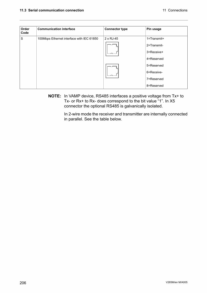
Pin usageConnector typeCommunication interfaceOrderCode
1=Transmit+2 x RJ-45100Mbps Ethernet interface with IEC 61850S
2=Transmit-
3=Receive+
4=Reserved
5=Reserved
6=Receive-
7=Reserved
8=Reserved
NOTE: In VAMP device, RS485 interfaces a positive voltage from Tx+ toTx- or Rx+ to Rx- does correspond to the bit value “1”. In X5connector the optional RS485 is galvanically isolated.
In 2-wire mode the receiver and transmitter are internally connectedin parallel. See the table below.
V265M/en M/A005206
11 Connections11.3 Serial communication connection
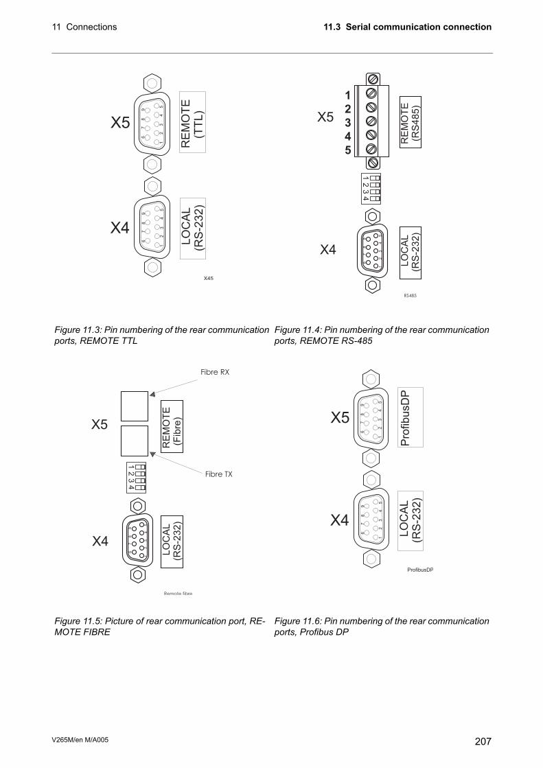
LO
CA
L(R
S-2
32
)R
EM
OT
E(R
S4
85
)
1
2
3
4
5
6
7
8
9
12
34
1
2
3
4
5
X5
X4
RS485
LO
CA
L(R
S-2
32
)
X4
1
2
3
4
5
6
7
8
9
X5
RE
MO
TE
(TT
L)
6
7
8
9
1
2
3
4
5
X45
Figure 11.4: Pin numbering of the rear communicationports, REMOTE RS-485
Figure 11.3: Pin numbering of the rear communicationports, REMOTE TTL
LO
CA
L(R
S-2
32
)
X4
1 2 3
4 5
6 7 8
9
X5P
rofib
usD
P
6 7 8
9
1 2 3
4 5
ProfibusDP
1 2 3
4 5
6 7 8
9
LO
CA
L(R
S-2
32)
RE
MO
TE
(Fib
re)
12
34
Fibre RX
Fibre TX
Remote fibre
X5
X4
Figure 11.6: Pin numbering of the rear communicationports, Profibus DP
Figure 11.5: Picture of rear communication port, RE-MOTE FIBRE
207V265M/en M/A005
11.3 Serial communication connection11 Connections

Figure 11.7: Dip switches inRS-485 and optic fibre op-tions.
Function
Fibre optics
Function
RS-485
Switch positionDip switch number
Echo off2 wire connectionLeft1
Echo on4 wire connectionRight1
Light on in idle state2 wire connectionLeft2
Light off in idle state4 wire connectionRight2
Not applicableTermination OnLeft3
Not applicableTermination OffRight3
Not applicableTermination OnLeft4
Not applicableTermination OffRight4
11.3.3 X4 rear panel connector (local RS232 andextension RS485 ports)
SignalPinRear panel port(LOCAL)
No connection1
X4
Rx in, RS232 local2
Tx out, RS232 local3
DTR out (+8 V)4
GND5
No connection6
B- RS485 extension port7
A+ RS485 extension port8
No connection9
NOTE: In VAMP devices, a positive RS485 voltage from A+ to B-corresponds to bit value “1”. In X4 connector the RS485 extensionport is not galvanically isolated.
11.4 Optional two channel arc protection cardNOTE: When this option card is installed, the parameter "Arc card type" has
value "2Arc+BI/O". Please check the ordering code in Chapter 14Order information.
If the slot X6 is already occupied with the DI19 / DI20 digital inputcard, this option is not available, but there is still one arc sensorchannel available. See Chapter 11.5 Optional digital I/O card(DI19/DI20).
V265M/en M/A005208
11 Connections11.4 Optional two channel arc protection card

The optional arc protection card includes two arc sensor channels.The arc sensors are connected to terminals X6: 4-5 and 6-7.
The arc information can be transmitted and/or received through digitalinput and output channels. This is a 48 V dc signal.
Connections:
Binary input (BI)X6: 1
Binary output (BO)X6: 2
Common for BI and BO.X6: 3
Sensor 1X6: 4-5
Sensor 2X6: 6-7
The binary output of the arc option card may be activated by the arcsensors or by any available signal in the output matrix. The binaryoutput can be connected to an arc binary input of another VAMPprotection device.
11.5 Optional digital I/O card (DI19/DI20)NOTE: When this option card is installed, the parameter "Arc card type" has
value "Arc+2DI". With DI19/DI20 option only one arc sensor channelis available. Please check the ordering code in Chapter 14 Orderinformation.
If the slot X6 is already occupied with the two channel arc sensorcard (Chapter 11.4 Optional two channel arc protection card), thisoption is not available.
The DI19/DI20 option enables two more digital inputs. These inputsare useful in applications where the contact signals are not potentialfree. For example trip circuit supervision is such application. Theinputs are connected to terminals X6:1 – X6:2 and X6:3 – X6:4.
Connections:
DI19+X6:1
DI19-X6:2
DI20+X6:3
DI20-X6:4
NCX6:5
L+X6:6
L-X6:7
209V265M/en M/A005
11.5 Optional digital I/O card (DI19/DI20)11 Connections

11.6 External option modules
11.6.1 External LED module VAM 16DThe optional external VAM 16D led module provides 16 extraled-indicators in external casing. Module is connected to the serialport of the device’s front panel. Please refer the User manual VAM16D for details.
11.6.2 External input / output moduleThe device supports an optional external input/output modules usedto extend the number of digital inputs and outputs. Also modules foranalogue inputs and outputs are available.
The following types of devices are supported:
• Analog input modules (RTD)
• Analog output modules (mA-output)
• Binary input/output modules
EXTENSION port is primarily designed for I/O modules. This port isfound in the LOCAL connector of the device backplane and I/Odevices should be connected to the port with VSE003 adapter.
NOTE: If External I/O protocol is not selected to any communication port,VAMPSET doesn’t display the menus required for configuring theI/O devices. After changing EXTENSION port protocol to ExternalI/O, restart the relay and read all settings with VAMPSET.
V265M/en M/A005210
11 Connections11.6 External option modules

External analog inputs configuration (VAMPSET only)
DescriptionRange
Communication read errors
-
Point 2Scaled valueY2
-
S
c
a
l
i
n
g
X: -32000 – 32000
Y: -1000 – 1000
Modbus valueX2
-
Point 1Scaled valueY1
-
Modbus valueX1
-
Subtracted from Modbus value, before runningXY scaling
-
Offset-32000 – 32000
-
-
Modbus register type
-
InputR or HoldingR
-
-
Modbus register for the measurement
-
1 – 9999
-
-
-
Modbus address of the I/O device
-
-
1 – 247
-
Unit selection
-
C, F, K, mA, Ohm or V/A
-
-
Active value
-
Enabling for measurement
-
On / Off
211V265M/en M/A005
11.6 External option modules11 Connections

Alarms for external analog inputs
DescriptionRange
-
Hysteresis for alarm limits
-
-
0 – 10000
-
Limit setting
Alarm >>-
-21x107 – +21x107
-
-
-
Active state
-
-
-
- / Alarm
-
Limit setting
Alarm >-
-21x107 – +21x107
-
-
-
Active state
-
-
- / Alarm
-
Active value
-
-
Modbus register for the measurement
-
-
-
1 – 9999
-
Modbus address of the I/O device
-
-
1 – 247
Enabling for measurementOn / Off
Analog input alarms have also matrix signals, “Ext. Aix Alarm1” and“Ext. Aix Alarm2”.
V265M/en M/A005212
11 Connections11.6 External option modules
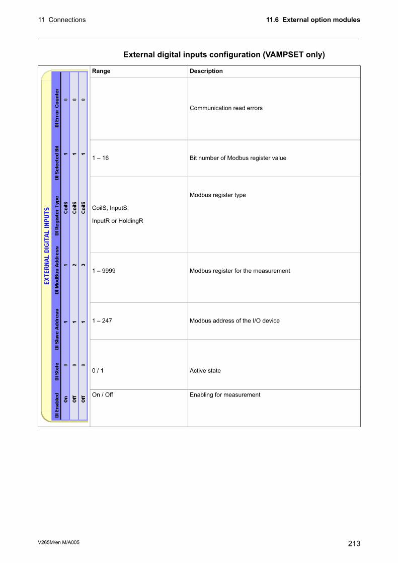
External digital inputs configuration (VAMPSET only)
DescriptionRange
-
-
Communication read errors
-
-
-
Bit number of Modbus register value
-
1 – 16
-
Modbus register type
-
-
CoilS, InputS,
InputR or HoldingR
-
-
-
Modbus register for the measurement
-
-
-
1 – 9999
-
Modbus address of the I/O device
-
-
1 – 247
-
-
Active state
-
-
-
0 / 1
-
Enabling for measurementOn / Off
213V265M/en M/A005
11.6 External option modules11 Connections

External digital outputs configuration (VAMPSET only)
DescriptionRange
-
-
Communication errors
-
-
-
-
Modbus register for the measurement
-
-
-
-
1 – 9999
-
-
Modbus address of the I/O device
-
-
-
-
1 – 247
-
-
Output state
-
-
-
-
0 / 1
Enabling for measurement-
V265M/en M/A005214
11 Connections11.6 External option modules

External analog outputs configuration (VAMPSET only)
DescriptionRange
-
Communication errors
-
-
Modbus value corresponding Linked Val. Max
--32768 – +32767
(0 – 65535) -
Modbus value corresponding Linked Val. Min
-
-
Modbus register type
-
-
InputR or HoldingR
-
Modbus register for the output
-
-
-
1 – 9999
-
Modbus address of the I/O device
-
-
1 – 247
-
Maximum limit for lined value, corresponding to “Modbus Max”
-0 – 42x108,
-21x108 – +21x108 -
Minimum limit for lined value, corresponding to “Modbus Min”
-
-
Link selection
-
-
Minimum & maximum output values
-
-21x107 – +21x107
-
-
Active value
-
Enabling for measurementOn / Off
215V265M/en M/A005
11.6 External option modules11 Connections

11.7 Block optional diagram
IL1
IL2
IL3
I01
I02
DI
Blocking andoutput matrix
Remote
Local
Front
X1:1
X1:2
X1:3
X1:4
X1:5
X1:6
X1:11
X1:12
X1:13
X1:16
X1:7
X1:8
X1:9
X1:10
X1:14
X1:15
X3:17
X3:18
A1
X3:10
X3:9
X3:11
T1
T2X3:15
X3:12
X3:13
X3:14
A2
A3
A4
A5
SF
X2:13
X2:14
X2:15
X2:10
X2:11
X2:12
X2:7
X2:8
X2:6
X2:5
X2:16
X2:17
X2:18
X5
X4
X3:1 +48V
X3:2 DI1
X3:3 DI2
X3:4 DI3
X3:5 DI4
X3:6 DI5
X3:7 DI6
Protection functions
X6:1
X6:2
X6:3
X6:4
X6:5
X6:6
X6:7
I’L1
I’L2
I’L3
~
T >
49
I >2 , I' >2
46
I >0
I >>0
50N/51N
3I>3I3I>>>>>
50 / 51
CBFP
50BF
ArcI>
50ARC
ArcI >01
02ArcI >
50NARC
Prg 1...8
9987
I>
ArcI'>
BI/O
L>
Figure 11.8: Block diagram of VAMP 265M
V265M/en M/A005216
11 Connections11.7 Block optional diagram

11.8 Block diagrams of option modules
11.8.1 Block diagrams of optional arc modules
Figure 11.9: Block diagram of optional arc protection module.
11.8.2 Block diagram of optional DI19/DI20
Figure 11.10: Block diagram of optional DI19/DI20 module with one arc channel.
217V265M/en M/A005
11.8 Block diagrams of option modules11 Connections

12 Technical data
12.1 ConnectionsTable 12.1: Measuring circuits
5 A (configurable for CT secondaries 1–10 A)Rated phase current
0 – 250 A- Current measuring range
20 A (continuously) / 100 A (for 10 s) / 500 A (for 1 s)- Thermal withstand
0.125 VA- Burden
0.005 Ohm- Impedance
1 A (configurable for CT secondaries 1 – 10 A)Rated phase current
0 – 50 A- Current measuring range
4 A (continuously) / 20 A (for 10 s) / 100 A (for 1 s)- Thermal withstand
0.04 VA- Burden
0.04 Ohm- Impedance
5 A (configurable for CT secondaries 1 – 10 A)Rated residual current (optional)
0 – 25 A- Current measuring range
20 A (continuously) / 100 A (for 10 s) / 500 A (for 1 s)- Thermal withstand
0.125 VA- Burden
0.005 Ohm- Impedance
1 A (configurable for CT secondaries 0.1 – 10.0 A)Rated residual current
0 – 5 A- Current measuring range
4 A (continuously) / 20 A (for 10 s) / 100 A (for 1 s)- Thermal withstand
0.04 VA- Burden
0.04 Ohm- Impedance
45 – 65 HzRated frequency fNMaximum wire dimension:Terminal block:
4 mm2 (10 – 12 AWG)- Solid or stranded wire
V265M/en M/A005218
12 Technical data

Table 12.2: Auxiliary voltageType B (option)Type A (standard)
18 – 36 V dc
Note! Polarity
X3:17= negative (-)
X3:18= positive (+)
40 – 265 V ac/dcRated voltage UAUX
-
15A with time constant of 1ms
25A with time constant of 1ms
Start-up peak (DC)
110V (Type A)
220V (Type A)
< 15 W (normal conditions)
< 25 W (output relays activated)
< 50 ms (110 V dc)
Power consumption
-
Max. permitted interruption time
Maximum wire dimension:
2.5 mm2 (13 – 14 AWG)
Terminal block:
- Phoenix MVSTBW or equivalent
Table 12.3: Digital inputs internal operating voltage6Number of inputs
0.00 – 60.00 s (step 0.01 s)Operation time
NO (normal open) or NC (normal closed)Polarity
-Inaccuracy:
±1% or ±10 ms- Operate time
48 V dcInternal operating voltage
approx. 20 mACurrent drain when active (max.)
< 1 mACurrent drain, average value
Maximum wire dimension:Terminal block:
2.5 mm2 (13 – 14 AWG)- Phoenix MVSTBW or equivalent
Table 12.4: Trip contact2 making contactsNumber of contacts
250 V ac/dcRated voltage
5 AContinuous carry
30 A
15 A
Make and carry, 0.5 s
Make and carry, 3s
Breaking capacity, DC (L/R=40ms)
5 Aat 48 V dc:
3 Aat 110 V dc:
1 Aat 220 V dc
AgNi 90/10Contact material
Wire dimension:
Maximum 2.5 mm2 (13 – 14 AWG)
Minimum 1.5 mm2 (15 – 16 AWG)
Terminal block:
- MSTB2.5 - 5.08
219V265M/en M/A005
12.1 Connections12 Technical data

Table 12.5: Signal contacts3 change-over contacts (relays A1, A2 and A3)Number of contacts:
2 making contacts (relays A4 and A5)
1 change-over contact (SF relay)
250 V ac/dcRated voltage
15 AMax. make current, 4s at duty cycle10%
5 AContinuous carry
2 000 VABreaking capacity, AC
Breaking capacity, DC (L/R=40ms)
1.3 Aat 48 V dc:
0.4 Aat 110 V dc:
0.2 Aat 220 V dc
Wire dimensionTerminal block
Maximum 2.5 mm2 (13 – 14 AWG)- MSTB2.5 - 5.08
Minimum 1.5 mm2 (15 – 16 AWG)
Table 12.6: Ethernet connection1Number of ports
Ethernet RJ-45 (Ethernet 10-Base-T)Electrical connection
VAMPSETProtocols
Modbus TCP
IEC 61850
10 Mb/sData transfer rate
Table 12.7: Local serial communication port1 on front and 1 on rear panelNumber of ports
RS 232Electrical connection
1200 - 38 400 kb/sData transfer rate
V265M/en M/A005220
12 Technical data12.1 Connections
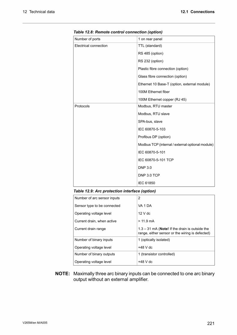
Table 12.8: Remote control connection (option)1 on rear panelNumber of ports
TTL (standard)
RS 485 (option)
RS 232 (option)
Plastic fibre connection (option)
Glass fibre connection (option)
Ethernet 10 Base-T (option, external module)
100M Ethernet fiber
100M Ethernet copper (RJ 45)
Electrical connection
Modbus, RTU master
Modbus, RTU slave
SPA-bus, slave
IEC 60870-5-103
Profibus DP (option)
Modbus TCP (internal / external optional module)
IEC 60870-5-101
IEC 60870-5-101 TCP
DNP 3.0
DNP 3.0 TCP
IEC 61850
Protocols
Table 12.9: Arc protection interface (option)2
VA 1 DA
12 V dc
> 11.9 mA
1.3 – 31 mA (Note! If the drain is outside therange, either sensor or the wiring is defected)
Number of arc sensor inputs
Sensor type to be connected
Operating voltage level
Current drain, when active
Current drain range
1 (optically isolated)
+48 V dc
Number of binary inputs
Operating voltage level
1 (transistor controlled)
+48 V dc
Number of binary outputs
Operating voltage level
NOTE: Maximally three arc binary inputs can be connected to one arc binaryoutput without an external amplifier.
221V265M/en M/A005
12.1 Connections12 Technical data

12.2 Test and environmental conditionsTable 12.10: Disturbance tests
Test valueStandard & Test class / levelTest
EN 61000-6-4 / IEC 60255-26Emission
0.15 – 30 MHzEN 55011, Class A / IEC 60255-25- Conducted
30 – 1000 MHzEN 55011, Class A / IEC 60255-25 / CISPR 11- Emitted
EN 61000-6-2 / IEC 60255-26Immunity
±2.5kVp CM, ±1.0kVp DMIEC 60255-22-1- 1Mhz damped oscillatory wave
80 - 1000 MHz, 10 V/mEN 61000-4-3 Level 3 / IEC 60255-22-3- Emitted HF field
2 kV, 5/50 ns, 5 kHzEN 61000-4-4 Level 3 / IEC 60255-22-4 ClassB
- Fast transients (EFT)
2 kV, 1.2/50 µs, CMEN 61000-4-5 Level 3 / IEC 60255-22-5- Surge
1 kV, 1.2/50 µs, DM
0.15 - 80 MHz, 10 VemfEN 61000-4-6 Level 3 / IEC 60255-22-6- Conducted HF field
300A/m (continuous)EN 61000-4-8- Power-frequency magnetic field
1000A/m, 1.2/50 µsEN 61000-4-9 Level 5- Pulse magnetic field
100ms / 100%IEC 60255-11- Voltage interruptions
12% of operating voltage (DC)IEC 60255-11- Voltage alternative component
30%/10ms, 100%/10ms,60%/100ms, >95%/5000ms
EN 61000-4-11- Voltage dips and short interrup-tions
Table 12.11: Electrical safety testsTest valueStandard & Test class / levelTest
5 kV, 1.2/50 µsEN 60255-5, Class III- Impulse voltage withstand
2 kV, 50 HzEN 60255-5, Class III- Dielectric test
EN 60255-5- Insulation resistance
EN 60255-27- Protective bonding resistance
IEC 60255-1- Power supply burden
Table 12.12: Mechanical tests10 – 60 Hz, amplitude ±0.035 mmVibration (IEC 60255-21-1)
60 – 150 Hz, acceleration 0.5gClass I
sweep rate 1 octave/min
20 periods in X-, Y- and Z axis direction
half sine, acceleration 5 g, duration 11 msShock (IEC 60255-21-1)
3 shocks in X-, Y- and Z axis directionClass I
Table 12.13: Environmental conditions-40 – 60°C (-40 – 140°F)Ambient temperature, in-service
-40 – 70°C (-40 – 158°F)Ambient temperature, storage
< 95%Relative air humidity
V265M/en M/A005222
12 Technical data12.2 Test and environmental conditions

Table 12.14: CasingIP54Degree of protection (IEC 60529)
208 x 155 x 225 mm / 8.19 x 6.10 x 8.86 inStandard model (w x h x d):
1 mm (0.039 in) steel plateMaterial
4.2 kg (9.272 lb)Weight
RAL 7032 (Casing) / RAL 7035 (Back plate)Colour code
Table 12.15: Package215 x 160 x 275 mm / 8.46 x 6.30 x 10.83 inDimensions (W x H x D)
5.2 kg (11.479 lb)Weight (Terminal, Package andManual)
223V265M/en M/A005
12.2 Test and environmental conditions12 Technical data

12.3 Protection functions*) EI = Extremely Inverse, NI = Normal Inverse, VI = Very Inverse, LTI = Long Time Inverse,MI= Moderately Inverse
**) This is the instantaneous time i.e. the minimum total operational time including thefault detection time and operation time of the trip contacts.
12.3.1 Differential protectionTable 12.16: Differential overcurrent stage ΔI> (87)
5 – 50 % INSetting range
0.50 x INBias current for start of slope 1
5 – 100 %Slope 1
1.00 – 3.00 x INBias current for start of slope 2
100 – 200 %Slope 2
5 – 30 %, or disableSecond harmonic blocking
20 – 50 %, or disableFifth harmonic blocking
< 95 ms
0.95
Reset time
Reset ratio
Inaccuracy:
±2% - unit- 2nd harmonic blocking
±3% - unit- 5th harmonic blocking
±3% of set value or 0.02 x INwhen currents are < 200 mA
- Starting
< 60 ms- Operating time (ID > 1.2 x ISET)
< 50 ms- Operating time (ID > 3.5 x ISET)
NOTE: The amplitude of second harmonic content has to be at least 2% ofthe nominal of CT. If the nominal current is 5 A, the 100 Hzcomponent needs to exceed 100 mA.
Table 12.17: Differential overcurrent stage ΔI>> (87)5.0 – 40.0 x INSetting range
< 95 msReset time
0.95Reset ratio
Inaccuracy:
±3% of set value or ±0.5% of rated value- Starting
< 40 ms- Operating time (ID > 3.5 x ISET)
V265M/en M/A005224
12 Technical data12.3 Protection functions
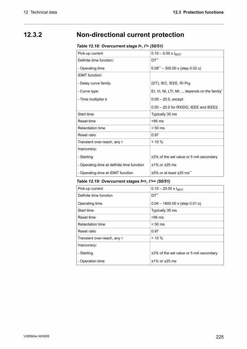
12.3.2 Non-directional current protectionTable 12.18: Overcurrent stage I>, I’> (50/51)
0.10 – 5.00 x IMOTPick-up current
DT**Definite time function:
0.08** – 300.00 s (step 0.02 s)- Operating time
-IDMT function:
(DT), IEC, IEEE, RI Prg- Delay curve family
EI, VI, NI, LTI, MI…, depends on the family*- Curve type
0.05 – 20.0, except- Time multiplier k
0.50 – 20.0 for RXIDG, IEEE and IEEE2
Typically 30 msStart time
<95 msReset time
< 50 msRetardation time
0.97Reset ratio
< 10 %Transient over-reach, any τ
-Inaccuracy:
±3% of the set value or 5 mA secondary- Starting
±1% or ±25 ms- Operating time at definite time function
±5% or at least ±25 ms**- Operating time at IDMT function
Table 12.19: Overcurrent stages I>>, I’>> (50/51)0.10 – 20.00 x IMOTPick-up current
DT**
0.04 – 1800.00 s (step 0.01 s)
Definite time function
Operating time
Typically 30 msStart time
<95 msReset time
< 50 msRetardation time
0.97Reset ratio
< 10 %Transient over-reach, any τ
-
±3% of the set value or 5 mA secondary
±1% or ±25 ms
Inaccuracy:
- Starting
- Operation time
225V265M/en M/A005
12.3 Protection functions12 Technical data

Table 12.20: Thermal overload stage T> (49)0.1 – 2.40 x IMOTMaximum continuous current:
60 – 99 % (step 1%)Alarm setting range:
2 – 180 min (step 1)Time constant Tau:
1.0 – 10.0 x Tau (step 0.1)Cooling time coefficient:
70 – 120 %IMOT (step 1)Max. overload at +40°C
50 – 100 %IMOT (step 1)Max. overload at +70°C
-55 – 125°C (step 1°)Ambient temperature
0.95Resetting ratio (Start & trip)
-
±5% or ±1 s
Accuracy:
- operating time
Table 12.21: Unbalance stage I2>, I’2> (46)2 – 70% (step 1%)Setting range:
-
1.0 – 600.0s s (step 0.1)
Definite time characteristic:
- operating time
-
Inv
1 – 50 s (step 1)
1000 s
Inverse time characteristic:
- 1 characteristic curve
- time multiplier
- upper limit for inverse time
Typically 300 msStart time
< 450 msReset time
0.95Reset ratio
-
±1% - unit
±5% or ±200 ms
Inaccuracy:
- Starting
- Operate time
NOTE: Stage is operational when all secondary currents are above 250 mA.
V265M/en M/A005226
12 Technical data12.3 Protection functions

Table 12.22: Stall protection stage (48)-
1.30 – 10.00 x IMOT (step 0.01)
1.50 – 10.00 x IMOT (step 0.01)
Setting range:
- Motor start detection current
- Nominal motor start current
DT, INVDelay type:
-
1.0 – 300.0 s (step 0.1)**)
Definite time characteristic (DT):
- operating time
-
1.0 – 300.0 s (step 0.1)
1.0 – 200.0 s (step 0.1)
Inverse time characteristic (INV):
- operation delay
- Inverse time coefficient, k
500 msMinimum motor stop time to activate stallprotection
200 msMaximum current raise time frommotor stopto start
0.10 x IMOT
0.20 x IMOT
1.20 x IMOT
Motor stopped limit
Motor running lower limit
Motor running limit after starting
Typically 60 msStart time
<95 msReset time
0.95Reset ratio
-
±3% of the set value or 5 mA secondary
±1% or at ±30 ms
±5% or at least ±30 ms
Inaccuracy:
- Starting
- Operating time at definite time function
- Operating time at IDMT function
NOTE: Motor stopped and running limits are based on the average of three phase currents.
227V265M/en M/A005
12.3 Protection functions12 Technical data

Table 12.23: Earth fault stage I0> (50N/51N)I01 (input X1:7 – 8)
I02 (input X1:9 – 10)
I0Calc (= IL1 + IL2 + IL3)
Input signal
0.005 – 8.00 pu (when I01 or I02)
0.05 – 20.0 pu (when I0Calc)
Setting range I0>
DT**
0.04** – 300.00 s (step 0.02 s)
Definite time function:
- Operating time
-
(DT), IEC, IEEE, RI Prg
EI, VI, NI, LTI, MI..., depends on the family*
0.05 – 20.0, except
0.50 – 20.0 for RXIDG, IEEE and IEEE2
IDMT function:
- Delay curve family
- Curve type
- Time multiplier k
Typically 30 msStart time
<95 msReset time
0.95Reset ratio
Inaccuracy:
±2% of the set value or ±0.3% of the ratedvalue
- Starting
±5% of the set value or ±2% of the ratedvalue (Sine wave <65 Hz)
- Starting (Peak mode)
±1% or ±25 ms- Operating time at definite time function
±5% or at least ±25 ms**- Operating time at IDMT function
Table 12.24: Earth fault stages I0>>, I0>>>, I0>>>> (50N/51N)I01 (input X1:7 – 8)
I02 (input X1:9 – 10)
I0Calc (= IL1 + IL2 + IL3)
Input signal
0.01 – 8.00 pu (When I01 or I02)
0.05 – 20.0 pu (When I0Calc)
Setting range
-
0.04** – 300.00 s (step 0.02 s)
Definite time function:
- Operating time
Typically 30 msStart time
<95 msReset time
0.95Reset ratio
Inaccuracy:
±2% of the set value or ±0.3% of the ratedvalue
- Starting
±5% of the set value or ±2% of the ratedvalue (Sine wave <65 Hz)
- Starting (Peak mode)
±1% or ±25 ms- Operate time
V265M/en M/A005228
12 Technical data12.3 Protection functions

12.3.3 Circuit-breaker failure protection CBFP (50BF)Table 12.25: Circuit-breaker failure protection CBFP (50BF)
-
0.1** – 10.0 s (step 0.1 s)
Definite time function
- Operating time
-Inaccuracy
- Operating time
12.3.4 Magnetising inrush 68F2Table 12.26: Magnetising inrush 68F2
-
10 – 100 %
0.05 – 300.00 s (step 0.01 s)
Settings:
- Setting range magnetishing inrush
- Operating time
-
±1% - unit
Inaccuracy:
- Starting
NOTE: The amplitude of second harmonic content has to be at least 2% of the nominalof CT. If the moninal current is 5 A, the 100 Hz component needs to exceed 100mA.
12.3.5 Over exicitation 68F5Table 12.27: Over exicitation 68F5
-
10 – 100 %
0.05 – 300.00 s (step 0.01 s)
Settings:
- Setting range over exicitation
- Operating time
-
±2%- unit
Inaccuracy:
- Starting
NOTE: The amplitude of fifth harmonic content has to be at least 2% of the nominal ofCT. If the moninal current is 5 A, the 250 Hz component needs to exceed 100 mA.
229V265M/en M/A005
12.3 Protection functions12 Technical data

12.3.6 Arc fault protection (option)The operation of the arc protection depends on the setting value ofthe ArcI>, ArcI01> and ArcI02> current limits.
The arc current limits cannot be set, unless the relay is provided withthe optional arc protection card.Table 12.28: Arc protection stage ArcI> (50ARC), ArcI01> (50NARC), ArcI02>(50NARC)
0.5 – 10.0 x INSetting range
S1, S2, S1/S2, BI, S1/BI, S2/BI, S1/S2/BI
13 ms
17ms
10 ms
0.01 – 0.15 s
< 3 ms
Arc sensor connection:
- Operating time (Light only)
- Operating time (4 x ISET + light)
- Operating time (BIN)
- Operating time (Delayed Arc L>)
- BO operating time
<95 msReset time
<120 msReset time (Delayed ARC L)
< 85 msReset time (BO)
0.90Reset ratio
-
10% of the set value
±5 ms
±10 ms
Inaccuracy:
- Starting
- Operating time
- Delayed ARC light
V265M/en M/A005230
12 Technical data12.3 Protection functions

12.4 Supporting functionsThe operation of disturbance recorder depends on the followingsettings. The recording time and the number of records depend onthe time setting and the number of selected channels.Table 12.29: Disturbance recorder (DR)
Saturated / OverflowMode of recording
Sample rate:
32/cycle, 16/cycle, 8/cycle- Waveform recording
10, 20, 200 ms- Trend curve recording
1, 5, 10, 15, 30 s
1 min
0.1 s – 12 000 min (According recorder set-ting)
Recording time (one record)
0 – 100%Pre-trigger rate
0 – 12Number of selected channels
The recording time and the number of records depend on the time setting and thenumber of selected channels.
231V265M/en M/A005
12.4 Supporting functions12 Technical data

13 Construction
VAMP 200 SERIES PANEL MOUNTING
27
1.06
181
7.13
28
1.10
137
5.39
1.0 -10
0.04 - 0.39
190
7.48
5
PROJECTION MOUNTING VAMP 200 SERIES
B A
21
0.83
>
Panel mounting
Projection mounting
20
0.79
Projection B Fixing bracket
VYX076 40 mm /1.57″ 169 mm/ 6.65″ Standard for 200 series
VYX077 60 mm /2.36″ 149 mm/ 5.87″ Standard for 200 series
VYX233 100 mm / 3.94″ 109 mm/4.29″ 2 x VYX199 needed
A
OK
Power
Error
Com
Alarm
Trip
A
B
C
OK
Power
Error
Com
Alarm
Trip
A
B
C
VAMP 200 series
VAMP 200 series
OK
Power
Error
Com
Alarm
Trip
A
B
C
VAMP 200 series
1.0-100.04 - 0.39
193
7.60
139
5.47
2
4
3
41
2a2b
mm
in
208
8.19
155
6.10
T max. 1.2N•m10.6 lb-in
18
17
16
15
14
13
12
11
10
T max. 0.5-0.6N•m4.4-5.3 lb-in
V265M/en M/A005232
13 Construction

4
VAMP 200 SERIES WALL ASSEMBLY FRAME TYPE V200WAF
3
V200WAF
245
9.65
2 mmin
32
1.26
181
7.13
32
1.26
80
3.15
OK
Power
Error
Com
Alarm
Trip
A
B
C
OK
Power
Error
Com
Alarm
Trip
A
B
C
1c
1b
11a
OK
Power
Error
Com
Alarm
Trip
A
B
C
T max. 1.2N•m10.6 lb-in
18
17
16
15
14
13
12
11
10
T max. 0.5-0.6N•m4.4-5.3 lb-in
233V265M/en M/A005
13 Construction

14 Order information
When ordering, please state:
• Type designation:
• Quantity:
• Options (see respective ordering code):
V265 - - Transformer and machine differential
Nominal current, HV & LV side [A]
1 = 1A & 1A
3 = 1A & 5A
4 = 5A & 1A
5 = 5A & 5A
Nominal earth-fault currents Io & I'o [A]
A = 5A & 5A
B = 5A & 1A
C = 1A & 5A
D = 1A & 1A
Frequency [Hz]
7 = Standard relay
Supply voltage [V]
A = 40.. 265Vac/dc
B = 18.. 36Vdc
C = 40.. 265Vac/dc + 1 x BI/BO, 2 x Arc sensor
D = 18.. 36Vdc + 1 x BI/BO, 2 x Arc sensor
E = 40.. 265Vac/dc + DI19, DI20 + 1 x Arc sensor
F = 18.. 36Vdc + DI19, DI20 + 1 x Arc sensor
Optional hardware
A = None
B = Plastic/Plastic serial fibre interface
C = Profibus interface
D = RS 485 interface (4-wire)
E = Glass/Glass serial fibre interface
F = Rx Plastic/Tx Glass serial fibre interface
G = Rx Glass/Tx Plastic serial fibre interface
H = RJ-45 10Mbps ethernet interface
M = RJ-45 10Mbps ethernet inc. IEC 61850
O = LC 100 Mbps ethernet fibre interface inc. IEC 61850
P = RJ-45 100Mbps ethernet interface inc. IEC 61850
R = 2 x LC 100 Mbps ethernet fibre interface inc. IEC 61850
S = 2 x RJ-45 100 Mbps ethernet interface inc. IEC 61850
Optional software
E = Transformer and machine differential firmware
M = Motor protection and machine differential firmware
Ingress protection rating
= IP30 (default)
I = IP54 (option)
Note:
(* Optional hardw are, A-H available
(# Optional hardw are, A-G available
V265M/en M/A005234
14 Order information

Accessories
NoteDescriptionOrder code
Ethernet adapterVEA 3CGi
Profibus DP fieldbus option boardVPA3CG
Max. distance 1 kmFibre optic Interface Module (plastic - plastic)VSE001PP
RS485 Interface ModuleVSE002
Local port RS-485 interface module,Ext I/O interfaceVSE003
External DeviceNet interface moduleVSE009
RTD Module, 12pcs RTD inputs, RS 485 Communication(24-230 Vac/dc)
VIO 12 AB
RTD/mAModule, 12pcs RTD inputs, PTC,mA inputs/outputs,RS232, RS485 and Optical Tx/Rx Communication (24 Vdc)
VIO 12 AC
RTD/mAModule, 12pcs RTD inputs, PTC,mA inputs/outputs,RS232, RS485 and Optical Tx/Rx Communication (48-230Vac/dc)
VIO 12 AD
Cable length 3mRS232 programming cable (VAMPSET, VEA 3CGi)VX003-3
USB to RS232 adapter3P025
Cable length 3mTTL/RS232 converter cable (PLC, VEA 3CGi)VX004-M3
Cable length 3mTTL/RS232 converter cable (VPA 3CG)VX007-F3
Cable length 6mArc SensorVA 1 DA-6
Disables rear local communicationExternal LED moduleVAM 16D
Height 40mmProjection for 200 seriesVYX076
Height 60mmProjection for 200 seriesVYX077
Height 100mmProjection for 200 seriesVYX233
V200 wall assembly frameV200WAF
235V265M/en M/A005
14 Order information
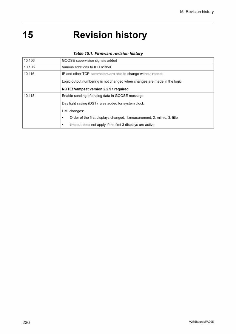
15 Revision history
Table 15.1: Firmware revision historyGOOSE supervision signals added10.106
Various additions to IEC 6185010.108
IP and other TCP parameters are able to change without reboot10.116
Logic output numbering is not changed when changes are made in the logic
NOTE! Vampset version 2.2.97 required
Enable sending of analog data in GOOSE message10.118
Day light saving (DST) rules added for system clock
HMI changes:
• Order of the first displays changed, 1.measurement, 2. mimic, 3. title
• timeout does not apply if the first 3 displays are active
V265M/en M/A005236
15 Revision history


+358 20 753 3200Phone:Yrittäjänkatu 15Street address:VAMP Ltd.+358 20 753 3205Fax:P.O. Box 810Post address:
m.vamp.fiInternet:FI-65101 [email protected]:
We reserve the right to changes without prior notice
2015
SchneiderElectric.A
llrightsreserved.
Customer Care Centre
http://www.schneider-electric.com/CCC
Schneider Electric
35 rue Joseph Monier92506 Rueil-MalmaisonFRANCE
Phone: +33 (0) 1 41 29 70 00Fax: +33 (0) 1 41 29 71 00
Publishing: Schneider Electricwww.schneider-electric.com04/2015Publication version: V265M/en M/A005