published by the national institute ... - university of idaho v08 2009-03-31.pdf · • darcy...
TRANSCRIPT


Published by the National Institute for Advanced Transportation Technology, April 2009 University of Idaho Moscow, Idaho Copyright 2009 – Michael Kyte

i
ACKNOWLEDGEMENTS The development of the MOST course was funded through a grant from the Federal Highway Administration. The development of the course materials was reviewed by a technical oversight committee. The members of the technical oversight committee include: • Eddie Curtis, Federal Highway Administration • Paul Olson, Federal Highway Administration. • Bill Kloos, City of Portland • Pam Crenshaw, Federal Highway Administration (now with the Federal Aviation Administration) • Mike Schauer, Federal Highway Administration • Raj Ghaman, Federal Highway Administration • Scott Frey, Federal Highway Administration • Shelley Row, Institute of Transportation Engineers (now with the Federal Highway Administration) • Jim Sturdevant, Indiana Department of Transportation • Zong Tian, University of Nevada • Ed Seymour, Texas Transportation Institute • Ken Courage, University of Florida • Peter Koonce, Kittelson and Associates The project team, and the laboratories for which they had responsibility, include: • Michael Kyte, University of Idaho, Principal Investigator (1, 2, 3, 5) • Michael Dixon, University of Idaho (1, 3, 5) • Ahmed Abdel-Rahim, University of Idaho (4) • Enas Amin, University of Idaho (2, 3, 4, 5) • Milan Sekulic, University of Idaho (1, 2, 3, 5) • Hua Wang, University of Idaho (2) • Azizur Rahman, University of Idaho (3) • Darcy Bullock, Purdue University (6, 7) • Anuj Sharma, Purdue University (6, 7) • Matt Wiesenfeld, Purdue University (6, 7) • Mike Inerowicz, Purdue University (6, 7) • Chris Day, Purdue University (6) • Tom Urbanik, University of Tennessee (2, 6, 7) • Jim Pline, Pline Engineering The development of the MOST simulation tools was led by Kiel Ova (PTV America) and Gary Duncan (Econolite).
ii
ELECTRONIC ACCESS TO MOST MATERIALS A Web site has been established at which you can access all MOST materials, including copies of these laboratory materials, all input files, and the MOST simulation software tools. Supplemental material for instructors is also available at this site. MOST Web site: http://www.webs1.uidaho.edu/MOST More information about the components of the MOST software simulation tools is available at the following Web sites: • The VISSIM simulation model is developed by PTV. More information about the model is available at:
http://www.ptvamerica.com/main.html • The Econolite ASC/3 controller emulator was developed by Econolite. More information about the controller emulator is available at:
http://www.econolite.com/

iii
CONTENTS Introduction to MOST 1 Glossary 13 Laboratory 1. Introduction to the Simulation Tools 19 Laboratory 2. Effect of Detector and Timing Parameters on the Operation of the Cross Street of an Isolated Intersection 55 Laboratory 3. Developing Timing Plans for Efficient Intersection Operations During Moderate Traffic Volume Conditions 113 Laboratory 4. Impact of Detector and Timing Parameters on Arterial Street Operations at an Isolated Intersection 165 Laboratory 5. Selecting Left Turn Phasing for Various Traffic Volume Conditions 231 Laboratory 6. Actuated Traffic Signal Coordination Concepts 259 Laboratory 7. Actuated Traffic Signal Coordination Implementation 351 References 395

iv

1
Introduction to MOST
2
CONTENTS (INTRODUCTION) 1. Welcome ........................................................................................................................................................................ 3
2. Our Approach ................................................................................................................................................................. 4
3. What We Expect You To Know ........................................................................................................................................... 5
4. What You Will Learn ........................................................................................................................................................ 6
5. The Study Site ................................................................................................................................................................ 8
6. The Simulation Tools ...................................................................................................................................................... 10
7. What a Laboratory Looks Like .......................................................................................................................................... 11
8. Your Next Step .............................................................................................................................................................. 12

Introduction to MOST
Section 1. Welcome 3
1. WELCOME Welcome to MOST, a new approach to learning about traffic signal timing. What is new about this approach? Our approach is new because we won’t tell you how to do traffic signal timing. What we will do is provide you with a new simulation environment in which you can directly observe how the signal timing parameters that you select affect the quality of traffic operations at a signalized intersection. You will learn by taking an active role in your learning process. The MOST course includes seven separate laboratories, with 37 individual experiments. Each experiment has one or more specific learning objectives that will guide your work during that experiment. Five of the laboratories cover isolated actuated intersection operations, while two cover coordinated signal systems. The traffic signal is one of the most important devices in the nation’s transportation system. Effective signal timing is a critical task for the transportation engineer. Yet many of the traffic signals that are currently in use today are not timed properly, are not installed correctly, are not used to their fullest extent, and are often not maintained properly. While the traffic signal is intended to provide for effective and efficient intersection operations, it is the one device that can require the public to wait unnecessarily if not properly designed and operated. There are an estimated 272,000 traffic signals in the United States. Any one of these traffic signals, or a system of several signals, can cause a motorist to wait unnecessarily when there is no other traffic on the other intersection approaches. The Federal Highway Administration estimates that three-quarters of these traffic signals, or over 220,000 traffic signals nationally, needs some sort of timing or operational improvement [5].
The traffic control industry itself has compounded this problem through the use of proprietary protocols. Proprietary protocols and communications standards limit the ability of the educational and training community to educate and train end users, whether practicing professionals or university students, on the operations of traffic signal controllers made by different manufacturers. In addition, manufacturers have implemented NEMA [9] or other standards in different ways, often using different definitions for what are common and well-defined traffic control parameters such as gap extension. The development and publication of the National Transportation Communications for ITS Protocol (NTCIP) provides a basis for opening up the way in which traffic control devices are designed and operated. Universities and other training institutions have also contributed to the problem. Most university classes cover fixed time equivalent traffic signal operations with little or no connection to the operation of actual traffic signal controllers. Most university laboratories do not have traffic signal controllers and are thus not able to give their students experience in their use. MOST gives you direct access to a real traffic controller, in software form. We believe that providing you with the MOST hands-on learning environment will allow you to participate in a very important experiment: how much can we reduce fuel consumption, reduce vehicle emissions, and better manage traffic flow in our cities by improving the timing of traffic signals? That is up to you. Welcome to this important work.

Introduction to MOST
Section 2. Our Approach 4
2. OUR APPROACH The MOST course is not about learning how to use a specific simulation model, though the experiments that you will complete are conducted using the VISSIM microsimulation model. Nor is it about a specific traffic signal controller, even though you will use Econolite’s ASC/3 controller emulator. Finally we will not present you with guidelines or standards that you should follow. The newly released Traffic Signal Timing Manual [5] produced by the Federal Highway Administration will provide you with this type of information. Rather, you will use the MOST simulation environment to directly see the results of the phasing plans and timing parameters that you select. Using VISSIM’s animation and movie files, you will visualize the duration of a green interval, the length of a queue, or the delay experienced by vehicles traveling through a signalized intersection with the phasing and timing plan that you design. And you will use this information to make judgments about the quality of intersection performance, and whether you need to make further adjustments to the signal timing to improve intersection operations. It is almost as good as standing out at an intersection, with one eye on the traffic and the other on what is happening in the controller cabinet. Educational research points to a hands-on active learning environment as the best approach to improving student understanding of important concepts. The highly successful Traffic Signal Summer Workshop developed at the University of Idaho has shown how students benefit directly from this approach. This workshop includes one week of hands-on experiences with traffic signal controllers and support hardware and software [7]. Two quotes, one from a student and one from an instructor, illustrate the benefits of the workshop experience.
“The best parts of the week were the hands-on work and introductory lectures to the more advanced technologies of
video detection and hardware-in-the-loop simulation. Exposure to this technology was worth the trip alone.”
“I think the valuable part is that students don’t just look at pictures or mathematical equations. They get a chance to tinker, make mistakes, and ultimately get various components up and running… much like they will have to in the real world. This means when they are on their first job and things don’t work exactly as expected during a [system] turn-on, they will have their wits about them and know how to debug the system and get it running.”
Unlike many courses that emphasize an instructor focus (with lectures presented to students), the MOST course emphasizes a student focus in which you will learn by doing the experiment, analyzing data that you collect, and drawing conclusions about what makes good signal timing practice.

Introduction to MOST
Section 3. What We Expect You To Know 5
3. WHAT WE EXPECT YOU TO KNOW The MOST course assumes that you are not starting at the beginning, that you do have some experience in transportation engineering, and especially traffic signal operations. The MOST course is targeted to signal technicians who implement signal timings in the field and traffic signal engineers who design, or someday will design, signal timing. This latter group includes university transportation engineering students. As a prerequisite to the course, we expect that you have four basic skills with respect to traffic signal operations. • You understand the concept of rings and barriers, and NEMA
phasing. Figure 1 illustrates a dual (two) ring, eight phase system, commonly used in actuated traffic signal controllers.
• You are able to sketch a scale drawing illustrating a time-distance diagram for at least two intersections, illustrating the cycle, split and offset parameters on a ring diagram for each intersection. (See Figure 2.)
• You understand basic detector operation, particularly inductive loop presence detection, and standard timing processes such as the Maximum Green time. (See Figure 3.)
• You are able to interpret the output from traffic signal optimization software such as Synchro, TRANSYT, or PASSER.
To improve your skills in these areas, and to make you better prepared to successfully complete the MOST course, we suggest that you consider the references provided at the end of this book, including the MOST Web site, where new links to other references are regularly updated.
Figure 1 NEMA dual ring diagram
Figure 2 Cycle, split, and offset with ring diagrams
Figure 3 Maximum Green timing process
Ring 1
Ring 2
1 2 3 4
5 6 7 8
Maximum Green timer setting

Introduction to MOST
Section 4. What You Will Learn 6
4. WHAT YOU WILL LEARN There is a lot to learn about traffic signal timing, more than you can learn in one course. But the seven laboratory exercises and 37 experiments that you will undertake in the MOST course covers a significant number of the basic issues that will improve your understanding and level of practice concerning the implementation of traffic signal operational parameters at both isolated intersections and in coordinated systems. The course will help to close the gap between only a rudimentary understanding of basic signal timing concepts and good practice. The best way to see what you will learn is to look at the laboratory title, its goal, and the learning objectives that have been established. These three items are presented in the text that follows. Laboratory 1. Introduction to the Simulation Tools • Goal: Learn how to use the MOST simulation tools. • Learning objectives: (1) Be able to use the MOST simulation
infrastructure to run simulations and manage VISSIM and the ASC/3 controller, and (2) Understand the animation features of VISSIM and the timing processes of the ASC/3 controller.
Laboratory 2. Effect of Detector and Timing Parameters on the Operation of the Cross Street of an Isolated Intersection • Goal: Develop a detector design (length of the detection zone)
and timing design (Minimum Green time and Vehicle Extension time parameters) for a cross street at an isolated intersection.
• Learning objectives: (1) Understand the relationship between detection zone length, detector location, Vehicle Extension time, and Minimum Green time for the operation of a phase, and (2) Be able to determine the duration of the Minimum Green time and the Vehicle Extension time given the length and placement of the detector.
Laboratory 3. Developing Timing Plans for Efficient Intersection Operations During Moderate Traffic Volume Conditions • Goal: Develop a timing plan for a signalized intersection with
moderate traffic volumes. • Learning objectives: (1) Be able to compare the operation of
the intersection with low and high values of Vehicle Extension time and understand the consequences of both alternatives, (2) Be able to determine the effect of the minor street Vehicle Extension time setting on the efficiency of major street and intersection operations, (3) Be able to determine pedestrian timing parameters using MUTCD procedures, (4) Be able to determine the Maximum Green time and understand its effect on intersection operations, and (5) Be able to set the timing parameters (Minimum Green time, Vehicle Extension time, and Maximum Green time) for both approaches of an intersection.
Laboratory 4. Impact of Detector and Timing Parameters on Arterial Street Operations at an Isolated Intersection • Goal: Develop a detector design (location of detection zone)
and timing design (Minimum Green time and Vehicle Extension time, as well as volume-density parameters) for the arterial street approach of an isolated intersection using advance detection.
• Learning objectives: (1) Analyze the performance of a high-speed approach when advance detection is used, (2) Determine the optimal values of Minimum Green time and Vehicle Extension time required when advance detection is used, (3) Identify issues associated with setting the Minimum Green time when advance detection is used and why it should be supplemented with either stop bar detection or the use of the volume-density variable initial setting, (4) Develop a timing plan that includes volume density variable initial parameters to improve the operation during initial queue service time, (5) Relate the duration of Vehicle Extension time to the intersection operation after the initial queue is served, and (6) Develop a timing plan that includes volume-density variable extension

Introduction to MOST
Section 4. What You Will Learn 7
(gap reduction) parameters to improve the operation after the initial queue is served.
Laboratory 5. Selecting Left Turn Phasing for Various Traffic Volume Conditions • Goal: Determine the appropriate left turn phasing for a given
volume condition. • Learning objectives: (1) Be able to compare the performance
of different left turn phasing alternatives, and (2) Understand the efficiency of different left turn phasing alternatives, and (3) Be able to determine an efficient left turn treatment.
Laboratory 6. Actuated Traffic Signal Coordination Concepts • Goal: Explain critical coordinated system timing parameters
and their effects on capacity allocation and platoon progression. • Learning objectives: (1) Experiment with and explain how
the three fundamental parameter settings, cycle, offset, and split, are used to define coordination, (2) Experiment with and explain how split times vary in a coordinated-actuated system, and how they operate in comparison to a fixed time system, (3) Experiment with and explain how the start of green in a coordinated-actuated system varies stochastically, and (4) Experiment with and control the reallocation of unused green time by selecting appropriate operating parameters.
Laboratory 7. Programming a System of Actuated Coordinated Signals • Goal: Give you an in-depth understanding of the database
elements required to define an actuated-coordinated traffic control system.
• Learning objectives: (1) Identify and describe all of the parameters needed to operate an actuated-coordinated traffic control system, (2) Successfully program a traffic controller with these parameters, and verify the operation of the system, and (3) Observe the operation of an actuated-coordinated traffic control system and identify various aspects of the performance of the system.
You can see that each laboratory builds a set of understandings and skills that culminate in a design problem or open-ended experiment. There is a wide range of topics starting from learning to use the simulation environment, to developing an understanding of the basic timing parameters for a cross street and the main street, to developing a timing plan for a coordinated signal system. These laboratory exercises form an integrated package of building blocks focusing on how a series of well-designed isolated intersections can be effectively operated as a system. The exercises start with a single approach and build towards a fully actuated intersection. Once the basic concepts of a well-functioning intersection are understood, you will use a system with two intersections to learn about the proper operation of a coordinated traffic signal system.

Introduction to MOST
Section 5. The Study Site 8
5. THE STUDY SITE You will learn about traffic signal timing using a real place, State Highway 8, a five-lane arterial located in the community of Moscow, Idaho. State Highway 8, shown here in Figure 4, consists of two through lanes in each direction and an exclusive left turn lane at each intersection. There is a distance of 3,065 feet between the intersections of Line Street on the right and Farm Road on the left. The intersection of State Highway 8 and Line Street (Figure 5) is the focus for the study of isolated actuated traffic control in Laboratories 2 through 5. Line Street includes an exclusive left turn lane and a shared through/right turn lane on each of its two approaches.
Figure 4 State Highway 8, Moscow, Idaho
Figure 5 Intersection of State Highway 8 and Line Street, Moscow, Idaho
State Highway 8
N
Introduction to MOST
Section 5. The Study Site 9
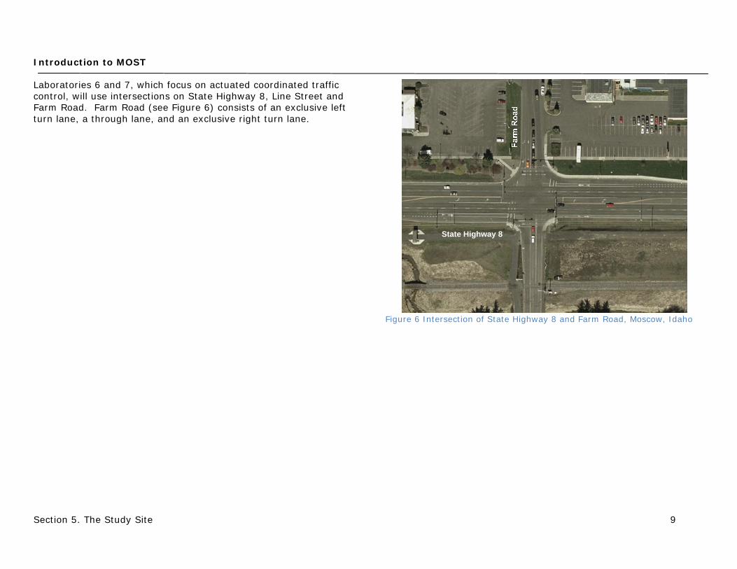
Laboratories 6 and 7, which focus on actuated coordinated traffic control, will use intersections on State Highway 8, Line Street and Farm Road. Farm Road (see Figure 6) consists of an exclusive left turn lane, a through lane, and an exclusive right turn lane.
Figure 6 Intersection of State Highway 8 and Farm Road, Moscow, Idaho
State Highway 8
Introduction to MOST
Section 6. The Simulation Tools 10
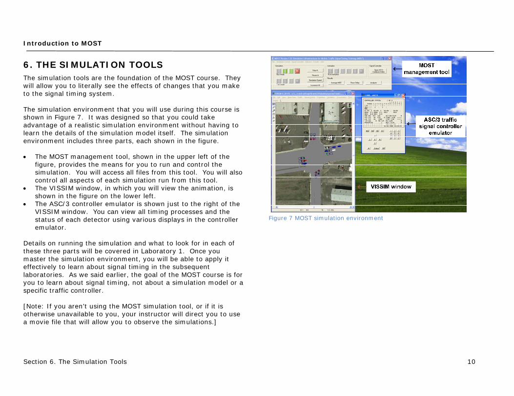
6. THE SIMULATION TOOLS The simulation tools are the foundation of the MOST course. They will allow you to literally see the effects of changes that you make to the signal timing system. The simulation environment that you will use during this course is shown in Figure 7. It was designed so that you could take advantage of a realistic simulation environment without having to learn the details of the simulation model itself. The simulation environment includes three parts, each shown in the figure. • The MOST management tool, shown in the upper left of the
figure, provides the means for you to run and control the simulation. You will access all files from this tool. You will also control all aspects of each simulation run from this tool.
• The VISSIM window, in which you will view the animation, is shown in the figure on the lower left.
• The ASC/3 controller emulator is shown just to the right of the VISSIM window. You can view all timing processes and the status of each detector using various displays in the controller emulator.
Details on running the simulation and what to look for in each of these three parts will be covered in Laboratory 1. Once you master the simulation environment, you will be able to apply it effectively to learn about signal timing in the subsequent laboratories. As we said earlier, the goal of the MOST course is for you to learn about signal timing, not about a simulation model or a specific traffic controller. [Note: If you aren’t using the MOST simulation tool, or if it is otherwise unavailable to you, your instructor will direct you to use a movie file that will allow you to observe the simulations.]
Figure 7 MOST simulation environment

Introduction to MOST
Section 7. What a Laboratory Looks Like 11
7. WHAT A LABORATORY LOOKS LIKE Each laboratory is similar in appearance and structure. In the first section, you will be introduced to the purpose of the laboratory and some relevant background material. The second section covers the important terms that will be discussed and used in the laboratory. We have tried to be consistent with the definitions used in three common references. Standard definitions for traffic signal terminology are provided by the National Electrical Manufacturers Association (NEMA) [9] and by the National Transportation Communications for ITS Protocol (NTCIP) 1202 document, “Object Definitions for Actuated Traffic Signal Controller Units” [2]. Definitions are also provided in the Federal Highway Administration’s Traffic Signal Timing Manual [5]. The definitions presented are adapted from these sources. Standard abbreviations are used for all directions and directional movements as follows: • Directions
o Eastbound: EB o Westbound: WB o Northbound: NB o Southbound: SB
• Directional movements o Through: TH o Left-turn: LT o Right-turn: RT
Following these two sections are the experiments themselves. Each experiment also has a consistent format. • One or more learning objectives. • An overview which provides a specific context that will guide
your work during the experiment. • A list of questions for you to consider during the experiment. • A list of the steps that you will follow during the experiment. • Details on running the experiment.
• A discussion of your results, considering the questions presented earlier and concluding your work for the experiment.
At the close of each laboratory is a summary of the key points that you learned. The files that you will need to run each experiment are provided for you, either as VISSIM input files or movie files that you can play using Windows Media Player or another similarly functional software tool. These files are provided either on a CD that accompanies this book or online at the MOST Web site for two computer screen resolutions: 1280x1024 for standard displays and 1680x1050 for wide screen displays. References are noted with a bracket and a number; for example, [3] refers to reference 3. One final note: While most of the experiments use the MOST simulation tools, you can, if necessary, complete the work without these tools. To facilitate this, we have provided movie files (in .wmv format) that duplicate all of the animations produced by the VISSIM simulations. We don’t recommend this as a first choice because we believe it is so valuable to learn how to change the signal timing parameters and then directly see the results. However, this approach is an acceptable second choice.

Introduction to MOST
Section 8. Your Next Step 12
8. YOUR NEXT STEP You are now ready to embark on your study of traffic signal timing, to learn how real traffic controllers work and what impact the controllers have on traffic operations and intersection performance. The MOST course is not simply reading. It is doing. You will gain the most from the course (this pun was intentional) if you take the time to work each of the experiments, collect the data or make the observations suggested, and think carefully about what the data and the observations tell you. If you do this, you will definitely improve your ability to develop effective signal timing plans for the real world. Best wishes with this important endeavor!

13
Glossary

Glossary
14
This Glossary provides the definitions for many of the technical terms used in the MOST book. Standard definitions for traffic signal terminology are provided by the National Electrical Manufacturers Association (NEMA) [9] and by the National Transportation Communications for ITS Protocol (NTCIP) 1202 document, “Object Definitions for Actuated Traffic Signal Controller Units” [2]. Definitions are also provided in the Federal Highway Administration’s Traffic Signal Timing Manual [5]. The definitions presented here are adapted from these sources. Actual Capacity: The maximum flow rate that could be served by a phase given its actual green time. Actual Green: The amount of effective green time that a phase actually receives in a cycle. If a phase gaps out, its actual green will be less than the programmed green. If a phase receives additional green time from another phase that gaps out, its actual green may be greater than the programmed green. Actuated Signal Control: A type of signal control in which the timing of each phase is at least partially controlled by detector actuations. Actuation: The operation of any type of detector. Added Initial: An interval that times concurrently with the Minimum Green interval, and is increased by each vehicle actuation received during the associated phase yellow and red intervals. The Added Initial is equal to the product of the number of vehicles arriving during the yellow and red intervals and the seconds per actuation. ASC/3 Virtual Controller: A software version of the ASC/3 controller, a NEMA-NTCIP compliant product, manufactured by Econolite.
Call: An actuation of a phase by vehicle detection or by an internal signal controller setting (a “recall”). A phase that is not called will be skipped. Capacity: The maximum flow rate that can be served by a phase at an intersection. The units of this measure may be given as vehicles per hour per lane or vehicles per hour. The capacity of a phase represents the maximum volume that could utilize the phase. Cycle Length: The amount of time needed to serve all of the called phases in a ring. Effective Green: The amount of time in each split that is used by vehicles for movement. Because the start-up lost time is equal to the amount of clearance time in which vehicles move, the effective green is equal to the amount of time that the green indication is shown. Effective Split: The proportion of the cycle that a phase is actually served. This may differ from the programmed splits, because of the reallocation of excess green due to phases gapping out. Excess or Unused Green: The amount of green time that is yielded by a phase when it gaps out, or is skipped. Fixed Force-Off: A force-off calculated relative to the cycle. Floating Force-Off: A force-off calculated relative to the beginning of the phase. Force-Off: The termination of a green indication at the point when the phase has reached its split time. The phase must terminate in order for following phases to be able to achieve their split times within the cycle length. Phases may extend beyond the split when they have acquired additional green time when preceding phases gap out or are not called.

Glossary
15
Gap in Effect: The current value of the Vehicle Extension time after the gap reduction process has begun. Gap Out: A method of terminating a phase resulting when the Passage Timer expires. Gap Reduction Process: This process reduces the time before a phase will terminate from the Passage Time to the Minimum Gap. This process is determined by three controller timing parameters: Time Before Reduction (TBR), Time To Reduce (TTR) and Minimum Gap. Gap Time: See Unoccupancy Time. Indication: The signal head color state (red, yellow, or green) displayed to a movement. Interval: The duration of time during which the indications do not change their state (active or off). Typically, one or more timing parameters control the duration of an interval. The green interval duration is controlled by a number of parameters including minimum time, maximum time, and gap time. Isolated Intersection: An intersection located outside the influence of and not coordinated with other signalized intersections, commonly one mile or more from other signalized intersections. Lagging Left Turn Phase: A traffic phase serving a left turn movement in which the through movement precedes the competing (opposite) left turn movement. Leading Left Turns: A traffic phase serving a left turn movement whose green leads the opposing through phase green. Lost Capacity: The maximum flow rate that can be served during the lost time, in which no movement takes place.
Lost Time: The amount of time in each split that is not used by vehicles for movement. It includes start-up lost time and unused clearance time. Max Out: A method of terminating a phase resulting when the Maximum Green time for the phase is reached. Maximum Green: The maximum length of time that a phase can be green in the presence of a conflicting call. Maximum Recall: A controller setting in which each phase is served to its force-off point. The controller operates as though there were calls constantly being placed on each detector. The resulting operation is equivalent to a fixed time plan. Maximum Initial: The maximum period of time for which the Added Initial can extend the initial green period. Minimum Gap: The minimum gap is used during the gap reduction process and is the smallest value for a vehicle extension. Minimum Green: The minimum amount of time for a green indication that must be given to a phase. Movement: A path of travel through an intersection that is regulated by a signal indication. Typical vehicle movements are left, through, and right. NEMA: Used to describe the set of standards developed by the National Electrical Manufacturers Association for actuated traffic control systems that are used in conjunction with NTCIP 1202. NTCIP: Acronym for the National Transportation Communications for ITS (Intelligent Transportation Systems) Protocol, a set of standards developed to enable open communications between various devices used in transportation systems. The standards

Glossary
16
document 1202, addressing protocols and objects for actuated traffic control systems, is used as a basis for terms and concepts throughout these laboratory exercises. Offset: The timing relationship between two signals that is used to define the relationship of either the start or end of particular phases at adjacent traffic signals. Passage Gap: See Passage Time. Passage Time: A parameter that specifies the maximum allowable duration of time between vehicle calls on a phase before the phase is terminated (Also called Vehicle Interval, Gap, Passage Gap, or Unit Extension) [Note: the term Vehicle Extension (in lieu of “Phase Time”) is used in this text, as this is the terminology used by the Econolite ASC/3 traffic controller, the controller that is part of the MOST simulation environment.] Pattern: A set of cycle timing parameters (including cycle length and splits) that is used to control an operation. The splits are distributed based upon expected demand for movements. Various patterns are programmed into a controller. Pedestrian Clearance Interval: The first clearance interval for the pedestrian signal following the pedestrian WALK indication. Permitted Left-Turn Phasing: A type of left turn phasing such that drivers must yield to opposing through traffic until safe gaps in the opposing traffic become available. Phase: A timing unit associated with the control of one or more indications or movements. Platoon Progression: Defining a timing relationship between adjacent controllers to facilitate the unimpeded movement of a platoon of vehicles through multiple signals along a signalized arterial.
Presence detector: A detector that registers a call that remains active as long as the vehicle is in the detection zone. Programmed Capacity: The maximum flow rate that can be served by a phase given its programmed green time. Programmed Green: The amount of effective green time that a phase would receive when in maximum recall mode. This time is determined by the split. Protected Left-Turn Phasing: A type of left turn phasing such left turning drivers have exclusive right of way. A green arrow is usually displayed to indicate protected left turn phasing. Protected/Permitted Left-Turn Phasing: A type of left turn phasing that is a combination of protected and permitted left turn phases. In this type of operation, drivers have right-of-way during the protected phase but can complete their maneuver on the permitted phase as opposing through movements permit. Ring: A series of phases that is repeated perpetually. In an eight-phase dual-ring configuration (shown in Figure 8), two rings run concurrently. Phases 1, 2, 3, and 4 form the upper ring, while phases 5, 6, 7, and 8 form the lower ring. The bold vertical lines in the figure are called barriers. A phase in one ring may run at the same time as a phase in the other ring that is on the same side of the barrier. For example, phase 1 may run at the same time as phase 5 or 6, but not at the same time as phase 2, or with phases 3, 4, 7, or 8.
Figure 8 Ring diagram for a dual-ring, eight-phase plan
1 2 3 4
5 6 7 8
Glossary
17
Saturation Flow Rate: The maximum rate of flow that can be sustained through a lane of travel at an intersection. In this laboratory, a rate of 1900 vehicles per hour per lane is assumed. Serviceable Conflicting Call: A call that occurs on a conflicting phase not having the right-of-way at the time the call is placed. Split: The percentage of a cycle that is expected to be used by a phase. This value is programmed into the controller, and used to determine the amount of green time given to the phase. Split Time: The amount of time that is given to a phase expressed in seconds rather than a percentage. Synchro: An optimization software program (http://www.trafficware.com/). Time Before Reduction (TBR): This period begins when the phase is green and there is a serviceable call on a conflicting phase. When this period is completed, the linear reduction of the Passage Time begins. Time of Day (TOD) Plan: The arrangement of controller patterns throughout a 24-hour period. Time To Reduce (TTR): The controller timing period that begins when the Time Before Reduction ends and controls the linear rate of reduction until the Minimum Gap is achieved. Unit Extension: See Passage Time. Unoccupancy time: The time that a detection zone is unoccupied, measured from the departure of the rear end of one vehicle from the zone to the arrival of the front end of the following vehicle in the detection zone. [Note: This term is sometimes referred to as “gap time.”]
Variable Initial: The Variable Initial is equal to the Added Initial, with the constraint that it must be greater than the Minimum Green or less than the Maximum Initial. Variable Initial Period: This period is the length of the initial green time that is needed to serve the standing queue that is present between the advance detector and stop bar at the beginning of the green interval. Vehicle Extension: See Passage Time. Vehicle Interval: See Passage Time. VISSIM: A simulation model developed by PTV Vision and the model that is used as part of MOST. It is one of several microscopic simulation models available today. It models traffic flow of individual vehicles including cars and trucks at signalized intersections and provides the realism of the varying performance of each vehicle. Volume to Capacity Ratio: (v/c) Estimated as the number of vehicles passing through an intersection (served vs. demand) in comparison to the theoretical capacity. Conventional wisdom indicates the lower the v/c the better the operation. Volume-Density Control: This type of control includes two components, a variable initial period and a gap reduction process. The initial period is not fixed by the Minimum Green time, but rather it varies based on the number of vehicles in queue at the beginning of green. The gap reduction process provides a reduction in the Passage Time over time based on the duration of the extension period. Walk Interval: An indication providing right-of-way to pedestrians during a phase.

Glossary
18