puch m125 - crankshaft oil seals · pdf filepuch m125 - crankshaft oil seals replacement ......
TRANSCRIPT
PUCH M125 - CRANKSHAFT OIL SEALS REPLACEMENT
1 of 14
This guide shows how to replace the two main crankshaft oil seals without the use of special locking tools. This is accomplished by pressing down hard on the brake pedal with the bike in gear therefore much of the disassembly is done with the engine in the frame. It also describes how to change the gearbox sprocket shaft seal without stripping the gearbox and how to change the crankshaft flywheel side seal. Use this guide in conjunction with the Repair Instructions page 6-3. Special tools and equipment: LH Crankcase Stand Repair Instructions page 6-5, Fig. 11. Flywheel Extractor Puch p/n 050.7012. (M26 x 1.5 with M12 bolt). Flywheel Holding Tool See Technical page. (Optional). Seal Insertion Discs Used to ensure seals are installed flush with housing
surfaces. Cut four discs from a sheet of 10-12mm hard plastic, plywood or MDF as follows. (I used an IKEA chopping board). 1) 42mm dia. x 21mm bore (for gearbox sprocket shaft seal) 2) 82mm dia. x 8mm bore. 2 off (for both main crankshaft seals). 3) 55mm dia. x 8mm bore (for flywheel and LH crankshaft seals).
Impact Driver May be required for crankcase cover screws. Club Hammer May be required for impact driver. Circlip Pliers Use of a Press Parts: Large Oil Seal x 2 NBR62X38X7 (901.3815) Crankshaft Bearings.
Note: You might read that standard Nitrile oil seals, prefixed NBR (generally black in colour), could be adversely affected by some unleaded petrol and that Viton seals (generally brown in colour) should be used instead. I sought the advice of a two-stroke engine specialist, who says that he has always used Nitrile crankshaft seals and has had no problems. If a seal is continuously immersed in petrol perhaps it may have an affect but where it’s used with an air/fuel mixture then I assume that it should be OK.
Small Oil Seal NBR35X20X7 (25152) Flywheel side. Small Oil Seal NBR32X20X7 (900.3803) G/Box Sprocket Shaft Oil Seal NBR28X16X7 (900.3809) Kickstart Shaft (If required).

PUCH M125 - CRANKSHAFT OIL SEALS REPLACEMENT
2 of 14
O Ring 12X18X3 (900.3881) Gear Lever Shaft. Gasket 366.1.10.013.1 (Cylinder Base). Gasket 366.0.10.004.1 (Cylinder Head). Or 366.2.10.004.1 or no gasket (as applicable). Gasket 366.1.10.031.1 (Crankcase). Gasket 366.1.10.049.1 (Crankcase Cover). Seal Ring 366.1.16.013.1 (Exhaust). Tab Washer 350.1.12.613.1 (Primary Gear). (If old tab washers have Tab Washer 331.1.14.032.1 (Gear Ratchet Axle). unused sections, new Tab Washer 366.1.13.018.1 (Gearbox Sprocket). ones are unnecessary) Fibre Washer 26482 (Oil Drain Plug). NOTE: Parts shown in photos are identified as e.g. Fig. 1.4, where Fig. 1 is the photo number and 4 is the part referenced. STEP 1 - At left-hand side of bike (1): 1) Remove silencer and exhaust pipe. 2) Select 4th gear. 3) Follow instructions to fit Flywheel Holding Tool (see Technical page) but if you
don’t have the tool, at the stage where it’s fitted, have an assistant press down hard on the brake pedal. Remove flywheel nut, screw in flywheel extractor, again with the brake pressed on, and tighten centre bolt to pull off flywheel. Retrieve the Woodruff key and keep in a safe place.
4) Remove air filter box cover, make a note of the positions of the wires at the bottom of the terminal block and disconnect wires. Feed cable through grommet and out of the box.
5) Make alignment marks on the magneto base plate at the positions of the three attachment screws, remove screws and baseplate and carefully loosen cable. Secure baseplate to air filter box.
6) The Motorcycle Mechanics magazine engine strip article states that it is essential to loosen, but not remove, the nut (Fig. 1.1) located above the gear lever shaft in order for the crankcases to be separated. The Puch manual does not have this instruction but I loosened it just in case.
7) Loosen the six crankcase bolts [5 x 50mm (Fig. 1.3) and 1 x 85mm (Fig. 1.4)], but do not remove them at this stage. (If bolts can’t be loosened using a screwdriver, then insert an appropriate size impact driver bit into a socket and use with a ratchet handle; this may be required upon reassembly as bolts should be tightened to a specific torque [but see warning]).

PUCH M125 - CRANKSHAFT OIL SEALS REPLACEMENT
3 of 14
Fig. 1 STEP 2 - At right-hand side of bike (1):
1) Drain gearbox oil and refit drain plug with new fibre washer. 2) Loosen footrest and rotate downwards. 3) Loosen carburettor clamp and pull carburettor from intake pipe and let it hang
on throttle cable. 4) Remove H.T. cap from spark plug. 5) Disconnect wires from brake light switch. 6) Make a note of how the clutch cable is secured to the operating lever and
crankcase cover lug. Loosen clutch control cable at the handlebar first then disconnect it from the crankcase cover.
7) Remove clutch-centring screw. 8) Unless the kickstart shaft oil seal is to be replaced (see Technical page), the
kickstart can be left in place. 9) Disconnect rear brake rod at rear wheel to allow removal of cover and refit
afterwards. 10) Undo cover bolts (6 x 70mm long and 1 x 85mm long at forward, lower
position Fig.2.6) and remove cover complete with kickstart mechanism. Retrieve the two dowels which may be loose. The long bolt was very tight; it took some heavy, club-hammer blows to an impact screwdriver to loosen.
Remove gasket. 11) Remove the circlip (Fig. 2.1) from the clutch set bolt and take out set bolt (Fig
2.2). If replacement of the clutch spring should not prove to be necessary the circlip can be reassembled. This way the clutch spring with spring cup and

PUCH M125 - CRANKSHAFT OIL SEALS REPLACEMENT
4 of 14
spring cage remain in pre-tensioned condition and when reassembling it is easier to tighten the fixing nut.
12) Knock back primary gear tab washer, stand astride bike and press down hard on rear brake pedal, (or have an assistant do so) and undo the primary gear nut (Fig. 2.3), and clutch nut which are both quite tight. Remove dished washer from beneath clutch nut.
13) Remove the clutch spring with spring cage and spring cup. Take out clutch discs. There are five identical steel discs and four identical discs with lining. The fifth disc with lining is without dog and is installed next to the crank web. Pull off clutch hub and clutch housing. The Puch manual says ‘remove bushing (Fig.3.1) from crankshaft journal’ which suggests that it should be a sliding fit, however it seemed to be a press fit and could not be moved. (I pressed the crankshaft through the bush when I removed it from the RH crankcase). Remove locking washer, small starter gear (Fig 2.4) and primary gear (Fig. 2.5). The Puch manual also says ‘Pull out bushing (Fig.3.2) from the countershaft; this bush has a sliding seat. The grooved side of the bushing is facing the gearbox’. (On my engine this bush would turn on the shaft, pull out a little way then felt and sounded as if it was hitting a stop. When I let go it retracted but I couldn’t think of what could be the cause). I left it in place when lifting the RH crankcase but it meant that the countershaft and gears came with it instead of remaining in the LH half as they should have done).
Fig. 2

PUCH M125 - CRANKSHAFT OIL SEALS REPLACEMENT
5 of 14
Fig. 3
STEP 3 - At left-hand side of bike (2): 1) Knock back gearbox sprocket tab washer (Fig. 1.5), press rear brake pedal hard
down, loosen sprocket nut (Fig. 1.6). 2) Remove chain joining link and remove chain. 3) Remove sprocket (Fig. 1.7) and intermediate piece. 4) Remove gearlever shaft circlip, covering disc and O ring. (Fig 1-2). 5) Clean shaft and disc; oil shaft and new O ring and fit O ring, covering disc and
circlip. 6) Disconnect brake rod at rear wheel. STEP 4 - Replace gearbox sprocket shaft oil seal: Note: This seal appears to be fitted with the lip facing outwards, the same as the kickstart shaft seal, although in this case I can’t find any reference to it in the Repair Instructions. However, the one I removed, the one shown in the Motorcycle Mechanics engine strip photos and the seal Parts List drawing all have it fitted this way. 1) Prise seal out of its housing using a flat bladed screwdriver.

PUCH M125 - CRANKSHAFT OIL SEALS REPLACEMENT
6 of 14
2) Clean the shaft and housing, oil the shaft, new seal lip and outside diameter. Mount seal on shaft, lip facing outwards, position Insertion Disc No. 1 against seal and using a piece of tubing, or a socket, gently tap the seal into place with a hammer.
3) Refit intermediate piece, sprocket, tab washer and nut. Tighten nut as much as possible. Final tightening will be done later.
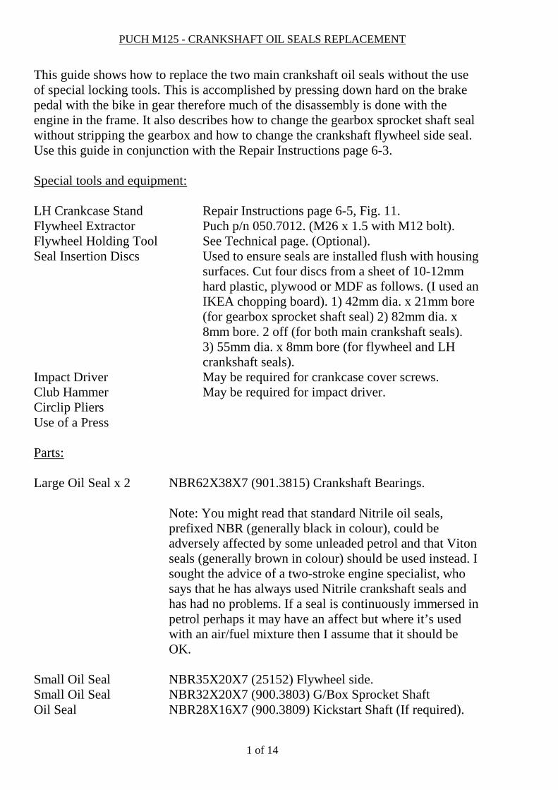
Note: It’s important that the sprocket nut and gearlever shaft O ring, covering disc and circlip are refitted before the crankcases are split otherwise the gearbox parts could fall out of the case. STEP 5 - Remove engine from frame: Unscrew the four engine mounting bolt nuts and remove the bolts and spring washers. Remove engine from the frame, in right-hand side direction. STEP 6 - Cylinder removal: With the engine on a bench, remove spark plug, loosen cylinder head nuts and remove cylinder head, plain washers and gasket (if fitted). Carry out a de-coke at this stage if necessary as described on page 3-5 of the ‘Handbook’ Operating Instructions. Loosen the four cylinder flange nuts. Motorcycle Mechanics suggests using a 6mm Allen key in-lieu of the special tool but mine were far too tight for that; also the correct torque could not be applied when refitting the nuts. It’s best to use a 6mm ¼ inch drive Allen socket if available but if not, cut about ½ inch off the end of a 6mm Allen key with a cutting disc, wrap a couple of turns of Sellotape round it and wedge it into a ¼ inch drive, 6mm socket (of no more than 12mm diameter). (The Allen key must be really tight in the socket). Using a 3 inch long ¼ inch drive extension, mated to a 3/8 inch drive to ¼ inch adaptor which in turn is mated to a ½ drive to a 3/8 inch adapter, a ½ inch drive handle can be fitted which will be needed to undo the nuts. (See Fig. 4). Note: Some of the nut Allen key recesses were full of a solid substance that was very difficult to remove. A scriber and a small screwdriver were used to dig out this crud from some of the nuts but one of the recesses had to be drilled with a long drill to remove it. The recesses were then filled with WD-40 and left for a few hours for it to seep down the threads to make removal a bit easier.
PUCH M125 - CRANKSHAFT OIL SEALS REPLACEMENT
7 of 14
Fig. 4
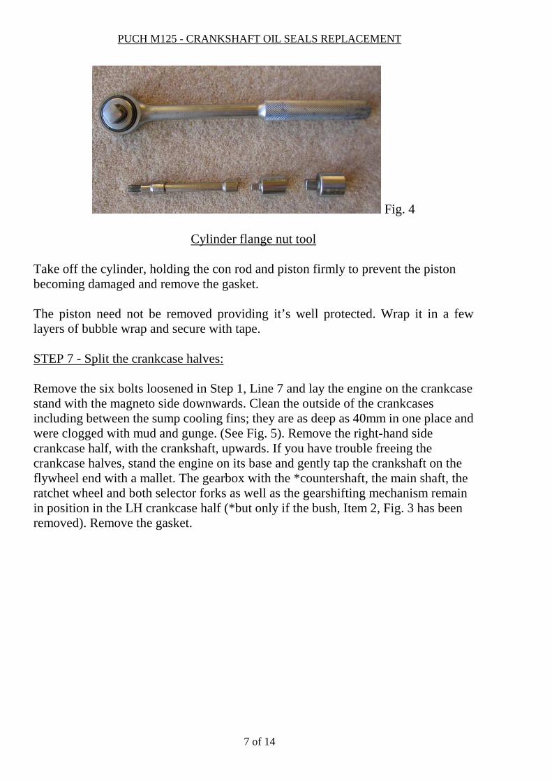
Cylinder flange nut tool Take off the cylinder, holding the con rod and piston firmly to prevent the piston becoming damaged and remove the gasket. The piston need not be removed providing it’s well protected. Wrap it in a few layers of bubble wrap and secure with tape. STEP 7 - Split the crankcase halves: Remove the six bolts loosened in Step 1, Line 7 and lay the engine on the crankcase stand with the magneto side downwards. Clean the outside of the crankcases including between the sump cooling fins; they are as deep as 40mm in one place and were clogged with mud and gunge. (See Fig. 5). Remove the right-hand side crankcase half, with the crankshaft, upwards. If you have trouble freeing the crankcase halves, stand the engine on its base and gently tap the crankshaft on the flywheel end with a mallet. The gearbox with the *countershaft, the main shaft, the ratchet wheel and both selector forks as well as the gearshifting mechanism remain in position in the LH crankcase half (*but only if the bush, Item 2, Fig. 3 has been removed). Remove the gasket.

PUCH M125 - CRANKSHAFT OIL SEALS REPLACEMENT
8 of 14
Fig. 5 STEP 8 - Replace LH Crankshaft and Flywheel side seals: With the LH crankcase half standing on its base, insert a ¼ inch parallel punch from the left, through the small flywheel side seal, and carefully knock round the large seal to remove it. To remove the flywheel side seal place the crankcase half in the stand and using a suitable socket or piece of tubing (Fig. 7.1), knock the seal downwards and out of the housing.
Fig. 6

PUCH M125 - CRANKSHAFT OIL SEALS REPLACEMENT
9 of 14
Fig. 7
With the large seal removed, a plastic spacer (with a smooth surface uppermost and a surface with protrusions underneath) is revealed. (Fig. 7.2). After having been pressed in, the top surface of both large oil seals must be on a level with the inner face of the crankcase. The spacer looks as if it’s there to ensure that the essential clearance of 2.5mm is kept between the bearing and the seal to prevent them coming into contact. (See Repair Instructions page 6-8, Fig. 18). The RH seal does not require a spacer, as there is a circlip above the bearing that prevents the seal contacting it. By using the Insertion Discs when fitting the seals, they will be correctly installed. Oil the seal outside diameters and the seal housings and tap the seals squarely, about ½ of their depth, into the housings using a suitable block of wood and a hammer. Place a penny washer on a suitable length M8 bolt, setscrew or piece of studding, followed by Disc No. 3. Pass the bolt through the housing from the left so that the disc rests against the small seal surface. (See Fig. 8). Place Disc No. 2 onto the bolt so that it rests against the large seal surface (See Fig. 9) and fit another penny washer and a nut. Slowly tighten the nut until both discs are flush with the housings.

PUCH M125 - CRANKSHAFT OIL SEALS REPLACEMENT
10 of 14
Fig. 8
Fig. 9
STEP 9 - Press out Crankshaft from RH Crankcase: The Puch manual shows the crankcase supported at three positions with a sturdy frame. As I couldn’t remove the countershaft, I roughly cut three wooden blocks to go round the flywheel and support the crankcase in the press. (Fig. 10 & 11). If you were able to remove the clutch bush and spacer, screw the clutch nut onto the shaft until it’s flush with the end to protect the thread before pressing out the crankshaft. As I had to press the crankshaft through the bush I cut the edges off a spare nut (M10 x 1mm) and filed it to a round shape. While the crankshaft is

PUCH M125 - CRANKSHAFT OIL SEALS REPLACEMENT
11 of 14
removed clean all traces of the old cylinder bottom and crankcase gaskets from the crankcase halves.
Fig. 10
Fig. 11
STEP 10 - Replace RH Crankshaft Seal: To remove the old seal, lay the RH crankcase on the stand, slide two penny- washers between the seal and the bearing (to protect the bearing) and carefully drill two small holes in the seal top surface, removing swarf as you go. Screw in two self-tapping screws to start a thread then remove them, cut off the tips and file the ends flat. Tighten the screws against the penny-washers and the seal should lift out of its housing. (See Fig. 12).

PUCH M125 - CRANKSHAFT OIL SEALS REPLACEMENT
12 of 14
Wash out the bearing with a solvent cleaner to remove any swarf then clean the seal housing. Oil the seal outer diameter and seal housing, place seal in position with the lip facing the bearing, and tap half way in using a wooden block and a hammer. Position one Insertion Disc No. 2 against the seal and one on the other side of the crankcase, and using the same method as in Step 8 tighten until the top of the seal is flush with the housing.
Fig. 12
STEP 11- Press Crankshaft into RH Crankcase: Oil the seal lip and the mating crankshaft ring, fit the flywheel nut until it’s flush with the end (to protect the threads). Support the crankcase in the press, place the crankshaft into position and press to fit. STEP 12 - Reassemble Crankcase Halves: Lay the LH crankcase half in the stand, lightly grease the gasket flange and place gasket in position. Oil the two seal lips and their crankshaft mating sections, taking care to avoid getting any oil on the flywheel taper. Lower the RH crankcase, with the crankshaft, into position; take care that the gasket does not move then fit the six crankcase nuts. Tighten with a screwdriver for now. Note: The two dowels remained in the RH crankcase half. STEP 13 - Refit Cylinder: Fit cylinder base gasket. Oil the cylinder bore and piston rings, lower the cylinder over the piston making sure the piston ring gaps are located correctly with their pins. Make sure the cylinder flange nut Allen key recesses are clean and the Allen key comes out easily, oiling the end if necessary. I had trouble with the cut off Allen

PUCH M125 - CRANKSHAFT OIL SEALS REPLACEMENT
13 of 14
key bit remaining in the nuts once they were tightened. Fit the flange nuts and tighten in a diagonal sequence to 13.5 Nm (10 ft/lb). STEP 14 - Refit cylinder head: Temporarily fit spark plug (to prevent nuts or washers falling into cylinder), fit new head gasket, fit cylinder head and plain washers and nuts and tighten in a diagonal sequence to either 24 Nm (18 ft/lb) for 8mm studs or 17.5 Nm (13 ft/lb) for 10mm waisted studs. STEP 15 - Refit primary gear, small starter gear and clutch assembly: (Can be done after engine has been refitted into frame but it’s easier on the bench). Lay the engine on the stand with magneto side down. Oil and fit the primary gear bush (grooved side facing gearbox), primary gear, small starter gear, new tab washer and nut. Tighten as far as possible. Fit the clutch spacer to the crankshaft (flat side facing outwards) and oil and fit the bush (grooved end facing outwards). Fit the clutch housing, clutch hub and clutch plates. Fit the spring cage, spring and dished washer (curved face outwards). Place the nut in a socket that is packed out so that the nut protrudes from it. Position the nut on the end of the crankshaft, press down against the spring pressure and carefully start the nut. STEP 16 - Install engine in frame: Place in engine in the frame from the RH side, reconnect the two brake light wires ensuring that the cable is not trapped and is correctly positioned. Grease the shanks of the four mounting bolts and fit them from the LH side. Fit new M8 spring washers and original nuts; tighten to 31 Nm (23 ft/lb). STEP 17 - Tighten gearbox sprocket, primary gear shaft and clutch nuts: Refit chain (closed end of joining link facing direction of travel) and brake rod. With an assistant pressing down hard on the brake pedal, tighten the sprocket nut to 64 Nm (47 lb/ft), the primary gear nut to 54 Nm (40 lb/ft) and the clutch nut to 43.5 Nm (32 lb/ft). Lock the sprocket and primary gear nut tab washers. Retighten the nut loosened in Step 1, Line 6 and lock the tab washer. Tighten the six crankcase screws: WARNING – The quoted torque figure of 11.5 Nm (8.5 ft/lb) seems too high for an M6 screw; a couple of them reached that torque but others felt as if the thread was about to strip so I stopped. An internet search gave various figures ranging from 4

PUCH M125 - CRANKSHAFT OIL SEALS REPLACEMENT
14 of 14
Nm (3 ft/lb) to 8 Nm (6 ft/lb) for M6 screws, depending upon the material properties. Most of the screws undid with a screwdriver anyway so if they are tightened as far as possible with one they should be OK. STEP 17 - Fit crankcase cover: Fit the clutch set bolt and circlip (with its flat face against the bolt). Lightly grease the crankcase flange and place gasket in position over the two dowels. The gasket is very fragile; mine broke but luckily it was at the top above the oil level. Fit the cover and tighten the 6 screws. Before screwing in the centring screw of the clutch set bolt make sure that the cut out on the declutching shaft points in driving direction. Screw in centring screw. Loosely fit the dipstick (to prevent clutch cable nuts falling into the gearbox). Fit clutch cable and adjust. Fill gearbox with 600cc of either SAE 20, 30, 40, or 50 non-detergent motor oil (depending upon the temperature). See ‘Handbook’ Operating and Maintenance instructions (page 3-1). STEP 18 - Refit magneto baseplate, fly wheel, wiring, LH cover: Fit baseplate with the 3 marks aligned with the screw holes. Ensure cable is correctly routed and reconnect wires at terminal block. The flywheel taper must be perfectly clean and dry (degrease if necessary). Fit flywheel, Woodruff key and nut. Using either the flywheel holding tool or by pressing down on the brake pedal, tighten nut to 34 Nm (25 ft/lb). Fit cover. STEP 19 - Refit carburettor, footrests (and brake pedal return spring at RH footrest), gear lever, exhaust pipe (with new seal ring) and silencer. Adjust rear brake and chain. Check that gears and clutch work correctly. STEP 20 - Prepare to start engine: With the spark plug removed, kick engine over a few times to distribute the gearbox oil. Refit plug and H.T. lead and start engine. Check for oil and exhaust leaks. Recheck oil level when engine is cold. SUMMARY: Apart from one tight screw and being unable to remove two bushes it was a relatively simple job. (I got the clutch bush to fit by dressing out the bore with 180 grade wet and dry paper). Everything is well designed and of sturdy construction. The original, 46 year old seals felt as if they were made from hard plastic rather than rubber so should have been replaced years ago.