pulsation-free hydraulic-driven swing tube piston pump · the hydraulic oil flow from this third...
TRANSCRIPT

Paste 2018 – RJ Jewell and AB Fourie (eds) © 2018 Australian Centre for Geomechanics, Perth, ISBN 978-0-9924810-8-7
Paste 2018, Perth, Australia 195
Pulsation-free hydraulic-driven swing tube piston pump
E Vlot Weir Minerals Netherlands B.V., The Netherlands
R Keijers Weir Minerals Netherlands B.V., The Netherlands
Abstract
A hydraulic-driven swing tube piston pump is normally equipped with two cylinders that move in opposite directions – one in suction and one in discharge. During the switchover from suction to discharge, the slurry discharge flow stops. During this time, the swing tube transfers from one cylinder to the other, and the hydraulic flow is diverted.
When the flow stops and starts again, the pressure drops abruptly and pressure spikes occur in the discharge slurry pipeline, causing high fluctuating loads and hydraulic hammering. This requires slurry pipeline reinforcements and additional supports, which requires additional investment costs. Also, the power drawn from the hydraulic power pack’s main motors fluctuates. This can result in a higher motor power rating and electrical system. On some occasions, the existing power supply system cannot handle these electric power fluctuations.
To reduce pulsations, a pulsation dampener can be installed in the discharge line. This dampener will supply slurry during the switchover of the pump, balancing the overall level of pulsations. Operators can choose to utilise either a nitrogen-charged dampener or a separate hydraulic-driven dampener, the latter performing somewhat better. These dampeners cannot prevent the pump from experiencing power fluctuations drawn from the main motors and will not reduce the discharge pressure pulsation level sufficiently.
To eliminate these power fluctuations, the following unique working principle has been developed: during the discharge stroke of one of the main cylinders, an additional flow above the nominal slurry flow is generated. This additional flow is sent to a third cylinder and absorbed. The hydraulic oil flow from this third cylinder is then transferred back to a hydraulic pump, which is mounted on the same motor shaft as the other hydraulic pumps and used for controlling the slurry cylinders. The additional energy required to move the third cylinder is fed back to the same motor shaft, so the only energy losses are friction and efficiency. During the swing tube switchover, the third cylinder will discharge the accumulated volume to the slurry pipeline, and thus continue the nominal pump discharge flow.
The third cylinder starts to build up momentum when the main slurry piston is slowing down to generate a theoretically smooth switchover from one cylinder to another. Due to the constant nominal flow, pressure fluctuations in the pump discharge line are reduced to a minimum level. Due to the energy recovery from the third cylinder during its suction stroke, fluctuations in power consumption are minimised to the level of friction and efficiency loss of the hydraulics of the third cylinder. A non-return valve is installed in the main slurry line directly after the pump to prevent backflow from the third cylinder to the pump.
Keywords: hydraulic-driven swing tube piston pump, pulsation-free
1 Introduction to hydraulic-driven pumps
A hydraulic-driven piston pump is typically a two-cylinder, single-acting, positive displacement pump, consisting of a pump unit and a hydraulic power unit (HPU). The HPU drives one or more hydraulic pistons that are connected to the slurry pistons. When a piston moves backwards (suction stroke), the cylinder space in front of the slurry piston is filled with slurry. When the piston moves in the opposite direction (discharge stroke), the slurry is discharged from the cylinder into the main slurry line.
https://papers.acg.uwa.edu.au/p/1805_15_Vlot/

Pulsation-free hydraulic-driven swing tube piston pump E Vlot and R Keijers
196 Paste 2018, Perth, Australia
The pump cylinders can either be connected to a valve box or a swing tube box, also referred to as the pump liquid end. These pump types are utilised for handling slurries that are highly viscous. A valve-operated pump allows for smaller particles to be pumped compared to a swing tube pump. In many paste backfill installations, valve-operated pumps are used when particles are no larger than 10 mm. When dealing with larger particles, up to 25 mm, swing tube pumps need to be used as larger particles can get jammed between the valve and seat.
All pump operations are sequence-controlled by a programmable logic controller (PLC). Please refer to Figures 1 and 2 for a typical cross-section of a valve and a swing tube pump.
Figure 1 Typical cross-section of valve pump
Figure 2 Typical cross-section of swing tube pump
Most pumps are equipped with two slurry cylinders, where one is in discharge mode and the other in suction mode. For a ‘standard’ pump, the two hydraulic cylinders are interconnected ensuring that the two pistons always move in opposite directions at the same speed. When one cylinder is performing a suction stroke, the other cylinder is performing a discharge stroke at exactly the same speed. Typically, the pump is driven by a hydraulic power pack containing one or more main oil pumps. A schematic of the hydraulic plan is shown in Figure 3.

Transportation
Paste 2018, Perth, Australia 197
Figure 3 Hydraulic schematic of a standard piston pump
Alternatively, the flow can be reversed or controlled by the hydraulic pump(s), so the two cylinders are operating independently.
Due to the reciprocating motion of the pistons, the discharge flow is discontinuous. During the discharge, as well as the suction stroke, the flow is proportional to the piston speed. At the reversal point of the pistons, the piston speed and resulting discharge flow is zero. During the standstill of the pistons, the valves or swing tube switch from suction to discharge mode (and vice versa for the second cylinder). This is called the switchover time. Figure 4 shows a typical flow versus time diagram of a standard piston pump as well as a hydraulic response. In the same figure, the average discharge flow is indicated.
Figure 4 Typical flow and pressure characteristic of a standard piston pump
These flow direction changes cause significant pressure spikes in the system. This typical hydraulic pump phenomenon had to be dealt with and addressed in the system design.

Pulsation-free hydraulic-driven swing tube piston pump E Vlot and R Keijers
198 Paste 2018, Perth, Australia
2 Reducing flow and pressure pulsations
A discontinuous flow results in pressure pulsations. The effect of the pressure pulsations on the piping depends on the design of the pipeline system downstream of the pump and is influenced by a number of factors including the pipe length, diameter and bends.
Pressure pulsations are the result of a change in flow. Every start and stop of slurry in the discharge pipeline causes pressure pulsations. Pressure pulsations can create enormous forces on the pipeline and the pumping system in general.
A way to reduce pressure pulsations is to use a pulsation dampener in the discharge pipeline. A pulsation dampener is a vessel that is pre-pressurised with gas (usually nitrogen) and has a rubber diaphragm that separates the gas from the slurry. A schematic is shown is Figure 5. The dampener is placed in the discharge line close to the pump for optimal performance.
Figure 5 Pulsation damper
The gas is pre-compressed to a certain value that is determined by the operating pressure of the system. Any sudden change in the pump flow will be compensated for by the dampener, consequently reducing the pulsation. The level of dampening depends mainly on the size of the dampener. Figure 6 shows a typical dampener characteristic.
Figure 6 Typical pressure dampening characteristic of a pulsation dampener

Transportation
Paste 2018, Perth, Australia 199
Besides the fact that the pulsations are only reduced in part, a dampener only works in a specific operating range. Any deviation from the operating pressure affects the correct functioning of the damper. Alternatively, a controlled pulsation dampener can be used.
When pumping a cemented paste for mine backfill, a dampener cannot be used because the hardening slurry will block the dampener over time and stop functioning as required.
In some cases, other equipment can be used for pulsation dampening such as a level-controlled air vessel. These alternatives operate in a similar way to the pulsation dampener, and although they have some other advantages and disadvantages, they will not be further described in this paper.
3 Pulsation-free dual hydraulic cone valve pump (accelerated suction
stroke system)
The most effective way of dealing with the phenomenon of pressure pulsations is to avoid generating them. This is done by creating a discharge flow that is continuous despite the reciprocating motion of the pistons. With a two-cylinder pump this can be achieved if both pistons are driven independently of each other. Figure 7 shows a schematic of this concept. Using this concept, the pump is divided into two single-cylinder pumps each driven by its own hydraulic system. The individual systems are controlled by a PLC that controls the respective piston speed profiles so that the total net discharge flow is constant, resulting in a constant discharge pressure.
Figure 7 Schematic concept of pulsation-free dual hydraulic cone (DHC) valve pump
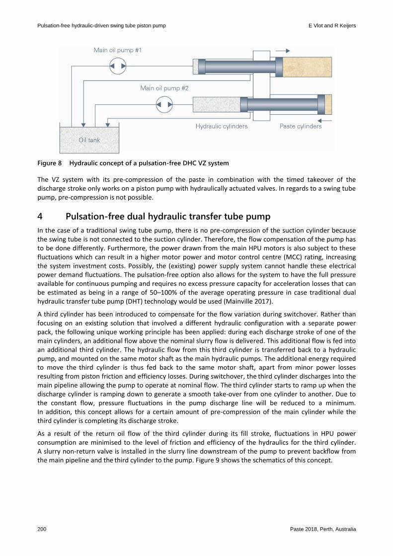
The speed profile of the individual pistons can only be controlled if their respective positions and speeds are monitored continuously during the complete length of the stroke. This is achieved with a linear transducer system that is integrated in the hydraulic side of each cylinder. The timing of the piston speeds and the corresponding opening and closing of the valves is critical for the correct functioning of the system. As described previously, the VZ system (versnelde zuigslag in Dutch or accelerated suction stroke in English) requires both the cylinders to be driven independently from each other. Each cylinder is driven by its own dedicated oil pump. The hydraulic scheme is shown in Figure 8. Note that depending on the total required power, the two main oil pumps can be driven by the same electric motor.
Pulsation-free hydraulic-driven swing tube piston pump E Vlot and R Keijers
200 Paste 2018, Perth, Australia
Figure 8 Hydraulic concept of a pulsation-free DHC VZ system
The VZ system with its pre-compression of the paste in combination with the timed takeover of the discharge stroke only works on a piston pump with hydraulically actuated valves. In regards to a swing tube pump, pre-compression is not possible.
4 Pulsation-free dual hydraulic transfer tube pump
In the case of a traditional swing tube pump, there is no pre-compression of the suction cylinder because the swing tube is not connected to the suction cylinder. Therefore, the flow compensation of the pump has to be done differently. Furthermore, the power drawn from the main HPU motors is also subject to these fluctuations which can result in a higher motor power and motor control centre (MCC) rating, increasing the system investment costs. Possibly, the (existing) power supply system cannot handle these electrical power demand fluctuations. The pulsation-free option also allows for the system to have the full pressure available for continuous pumping and requires no excess pressure capacity for acceleration losses that can be estimated as being in a range of 50–100% of the average operating pressure in case traditional dual hydraulic transfer tube pump (DHT) technology would be used (Mainville 2017).
A third cylinder has been introduced to compensate for the flow variation during switchover. Rather than focusing on an existing solution that involved a different hydraulic configuration with a separate power pack, the following unique working principle has been applied: during each discharge stroke of one of the main cylinders, an additional flow above the nominal slurry flow is delivered. This additional flow is fed into an additional third cylinder. The hydraulic flow from this third cylinder is transferred back to a hydraulic pump, and mounted on the same motor shaft as the main hydraulic pumps. The additional energy required to move the third cylinder is thus fed back to the same motor shaft, apart from minor power losses resulting from piston friction and efficiency losses. During switchover, the third cylinder discharges into the main pipeline allowing the pump to operate at nominal flow. The third cylinder starts to ramp up when the discharge cylinder is ramping down to generate a smooth take-over from one cylinder to another. Due to the constant flow, pressure fluctuations in the pump discharge line will be reduced to a minimum. In addition, this concept allows for a certain amount of pre-compression of the main cylinder while the third cylinder is completing its discharge stroke.
As a result of the return oil flow of the third cylinder during its fill stroke, fluctuations in HPU power consumption are minimised to the level of friction and efficiency of the hydraulics for the third cylinder. A slurry non-return valve is installed in the slurry line downstream of the pump to prevent backflow from the main pipeline and the third cylinder to the pump. Figure 9 shows the schematics of this concept.

Transportation
Paste 2018, Perth, Australia 201
Figure 9 Schematic concept of pulsation-free DHT
The hydraulic scheme is presented in Figure 10.
Figure 10 Hydraulic concept of pulsation-free DHT
For a recent project, a pulsation-free DHT pump was built and commissioned. The pump design flow is 205 m3/hr against a design pressure of 120 bar. The pump was initially tested in operation without the third cylinder being activated. The resulting flow and pressure variation can be seen in Figure 11. As can be concluded from this figure, the variations are significant. In Figures 12 and 13, the pump flow, pressure and power draw with an activated third cylinder are shown. Activating pre-compression (Figure 13) allows the pressure pulsation level to be reduced to +5/-15% and the power draw fluctuation to be reduced to +/-15%. This is considered a significant improvement for this pump type.
The pulsation-free swing tube technology includes the following benefits:
Reduced power fluctuations in the electrical feed system.
Smaller-sized positive displacement pumps and related investment costs in the range of 10–15%.
Reduced costs for pipeline and pipeline supports in the range of 10–15%.

Pulsation-free hydraulic-driven swing tube piston pump E Vlot and R Keijers
202 Paste 2018, Perth, Australia
Figure 111 Flow and pressure variations for two cylinder operation
Figure 12 Pump curves with third cylinder without pre-compression

Transportation
Paste 2018, Perth, Australia 203
Figure 13 Pump curves with third cylinder including pre-compression
5 Conclusion
While a DHC hydraulic valve style pump is a constant flow/pulsation-free option and has been available for years, the same fully integrated concept is now also available for DHT pumps. Through the introduction of a third cylinder, combined with hydraulic oil recovery and pre-compression technology, this concept can now be applied for hydraulic-driven swing tube pumps. Pressure pulsations are minimised, as well as power fluctuations, and investment costs in the pumping and pipeline system can be reduced. The concept is patent pending and offers a unique solution to customers in the mining industry.
References
Mainville, P 2017, ‘Pulsations from positive displacement pumps’, Proceedings of the 12th International Symposium on Mining with Backfill, Society for Mining, Metallurgy and Exploration Inc., Englewood.

Pulsation-free hydraulic-driven swing tube piston pump E Vlot and R Keijers
204 Paste 2018, Perth, Australia