pumping tests with thermal logging in date: …€¦ · pumping tests with thermal logging in...
TRANSCRIPT

TITLE: REVISION: 1
NYE COUNTY NUCLEAR WASTEREPOSITORY PROJECT OFFICE
TEST PLAN
TEST PLAN NUMBER:
Pumping Tests with Thermal Logging in DATE: 11110/2011Early Warning Drilling Program WellsUsing Distributed Temperature Sensing PAGE: 10ft
Equipment
SUPERSEDES:
TPN-6.3 Revision 0, 111112010
CHANGE NOTICE NO. 1
EFFECTIVE DATE: 11/15/2011
PURPOSE: Specification of transducer-based temperature profiling procedureand equilibration times in Section 5.2, to provide in-field calibration data fortemperature data collected with the DTS unit.
CONCURRENCE: ~~/~~~~ %_M_~_~=I_I~anager Date
",~~~
v.~Principal Investigator
If It IDate

TPN-6.3 Rev 1 11/10/2011
Page 2 of 18
NWRPO work plan WP-6.0, Early Warning Drilling Program Geophysical Logging Work Plan, provides the background, purpose, and general objectives of geophysical data collection in EWDP boreholes and wells.
2.0 BACKGROUND AND PURPOSE
While conducting various phases of tracer testing activities at Site 22 in boreholes NC-EWDP-22S, -22PA, and -22PC, beginning in November 2004 and continuing through November 2009 (in accordance with NWRPO Test Plan TPN-9.5 Natural Gradient Cross-Hole Tracer Test at Site 22), it became apparent that discrete intervals within individual well screens in Zone 2 in these wells may be producing water at varying rates. Nye County believes that more detailed information on these features and others similar to them will lead to a better understanding of groundwater flow in Valley Fill Aquifer systems.
The collection of temperature data in existing observation wells 22PA and 22PC during pumping of well 22S using the DTS method described in this TPN will aid in identifying preferential flow pathways and improving estimates of flow and transport properties within individual screened units.
The technique will be tested at well NC-EWDP-4PD and nearby observation wells prior to testing at Site 22. Site 22 is located in Fortymile Wash down gradient from Yucca Mountain in the southwest corner of the Nevada National Security Site (NNSS), and well 4PD is located down gradient of Site 22 in Fortymile Wash outside of the NNSS boundary.
3.0 SCOPE OF WORK
3.1 Responsibilities
The Principal Investigator (PI) is responsible for supervising the data collection activities described in this TPN. NWRPO personnel, including staff and contract geologists and technicians, are responsible for conducting the activities described in this TPN.
The Field Safety Supervisor (FSS) is responsible for monitoring the health and safety of workers relative to the guidelines established in the NWRPO Site Specific Health and Safety Plan (SSHASP).
The Site Supervisor is responsible for ensuring the completion of work in a safe manner according to the guidelines established in this TPN.
Nye County Field Personnel, as assigned by the PI, FSS or Site Supervisor are responsible for the completion of the activities described in this TPN.
Initial setup and calibration of DTS field equipment will be done by UNR personnel following CTEMPs guidelines as directed by the PI. Subsequent setup and calibration of
TPN-6.3 Rev 1 11/10/2011
Page 3 of 18
DTS field equipment may be done by Nye County Field Personnel as directed by the PI in consultation with the Geoscience Manager.
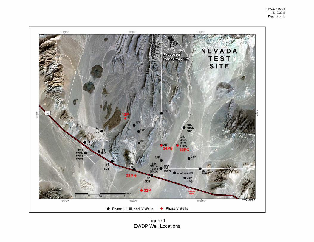
3.2 Well Locations
Figure 1 shows the locations of existing EWDP wells. Temperature logging work will be conducted in wells 4PA and 4PB during pumping in well 4PD, and in wells 22PA and 22PC during pumping in well 22S. Well completion diagrams for these wells are shown in Figures 2 through 7.
3.3 Equipment Requirements
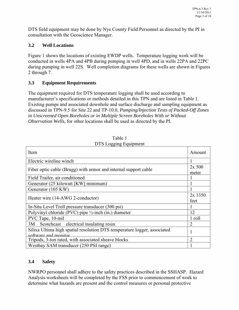
The equipment required for DTS temperature logging shall be used according to manufacturer’s specifications or methods detailed in this TPN and are listed in Table 1. Existing pumps and associated downhole and surface discharge and sampling equipment as discussed in TPN-9.5 for Site 22 and TP-10.0, Pumping/Injection Tests of Packed-Off Zones in Unscreened Open Boreholes or in Multiple Screen Boreholes With or Without Observation Wells, for other locations shall be used as directed by the PI.
Table 1
DTS Logging Equipment
Item Amount
Electric wireline winch 1
Fiber optic cable (Brugg) with armor and internal support cable 2x 500 meter
Field Trailer, air conditioned 1Generator (25 kilowatt [KW] minimum) 1Generator (105 KW) 1
Heater wire (14-AWG 2-conductor) 2x 1350 feet
In-Situ Level Troll pressure transducer (300 psi) 1Polyvinyl chloride (PVC) pipe ½-inch (in.) diameter 12 PVC Tape, 10-mil 1 roll3M� Scotchcast� electrical insulating resin 2Silixa Ultima high spatial resolution DTS temperature logger, associated software and monitor
1
Tripods, 3-ton rated, with associated sheave blocks 2Westbay SAM transducer (250 PSI range) 1
3.4 Safety
NWRPO personnel shall adhere to the safety practices described in the SSHASP. Hazard Analysis worksheets will be completed by the FSS prior to commencement of work to determine what hazards are present and the control measures or personal protective

TPN-6.3 Rev 1 11/10/2011
Page 4 of 18
equipment (PPE) necessary to mitigate them. All personnel shall wear appropriate PPE at all times and stop work if life-threatening or otherwise unsafe conditions develop or are observed. Work shall resume only when actions have been taken to correct unsafe conditions and all on-site personnel have been briefed.
Note that the Silixa Ultima DTS is a Class 1M laser product, and care should be taken to avoid looking directly into or magnifying the laser while it is energized. Users should refer to the manufacturer’s documentation (Silixa Ultima Quick Start Guide) for the DTS safety warnings and precautions.
4.0 PUMP INSTALLATION AND DATA COLLECTION
Preparation for possible pump operations shall include the following steps:
1. Place the generator specified onsite on secondary containment, as specified in the SSHASP. Hang a suitable pump control panel on the generator.
2. At the direction of PI, direct the pumping contractor to lift the submersible pump and motor, with the pumping rig, slightly off the ground so that the pump is in a vertical position.
3. Tape a 250-psia Stand-Alone Module (SAM) as close as possible to the top of the 5-foot-long pump. The SAM must be less than 7 feet above the pump intake. Protect the SAM with the spider centralizer.
4. Record the distance between the midpoints of the pump intake and the SAM in the scientific notebook.
5. Run the submersible pump into well on the 2-inch galvanized steel pipe, being careful to avoid damaging the SAM cable. Tape the SAM cable to the pipe above and below each collar as it is being fed into the hole.
6. Set the bottom of the pump 3 feet above the top of the existing PVC pipe/MP55 casing connection to maximize available drawdown for the pump.
7. Record all depth control information on a Tubing and Casing Record, found in TP-7.0, Drill Site Management.
8. Connect the pump controller and pump to the electrical panel on the 105 KW generator.
9. Ensure that the pumping contractor remains onsite until the submersible pump has been started.
10. Connect a 2-inch galvanized steel pipe with ¼-inch sample port and flexible discharge line to the submersible pump at the wellhead. Ensure that a 2-inch flow meter is in a straight run of pipe at least 3 feet from any upstream or downstream

TPN-6.3 Rev 1 11/10/2011
Page 5 of 18
flow disturbance, such as bends or valves. Ensure a 2-inch control ball valve is installed at least 3 feet downstream of the flow meter.
11. Photograph the discharge line to comply with permit regulations. Note: this step may be omitted if camera permits have not been issued by the time work commences.
12. Utilizing the procedure described in TP-9.9 Measurement of Groundwater Levels Using Electric Well Sounders, use a manual water level meter to measure the depth to water in Screen 2 in 22S, 22PA, and 22PC; or in 4PA, and 4PB. Record these measurements in the Scientific Notebook.
13. Attach the Westbay transducer in pumping well to the data logger, set the recording interval as directed by the PI, and begin logging data. Continue logging until the pumping described in Section 6 is stopped and the PI or FSS directs logging to stop.
5.0 DTS INSTRUMENTATION AND DATA COLLECTION
The DTS system will utilize a Silixa Ultima high spatial resolution 1M laser system available from the National Science Foundation sponsored CTEMPs. The system will consist of a minimum 2 channel DTS and associated on-board computer and data acquisition system. Data will be stored on board the system. The systems will be capable of collecting and stacking distributed temperature data along the length of a fiber optic cable at user-defined intervals at a spatial resolution of 25 cm.
Raw stokes/anti-stokes intensity data will be processed in the field based on initial calibration using proprietary software from Silixa. Further processing of field data based on downhole Level Troll temperature data, discharge temperature data, and calibration bath data will be done by UNR after completion of field work.
Be sure to collect manual water level measurements as directed in Section 4 prior to installation of DTS equipment.
5.1 Cable Preparation
The heater wire will be run in series in both 22PA deep and 22PC deep. Each end of the heater wire shall be prepared as follows:
1. Split the two conductor wires apart approximately 2-inches (in.) at the end of the wire.
2. Strip 1-in. insulation from the end of each wire.
3. Twist the two wires together and solder the connection.
4. Place the wires inside a 4-in. long section of ½-in. outside diameter PVC pipe.
TPN-6.3 Rev 1 CN 1 11/15/2011
Page 6 of 18
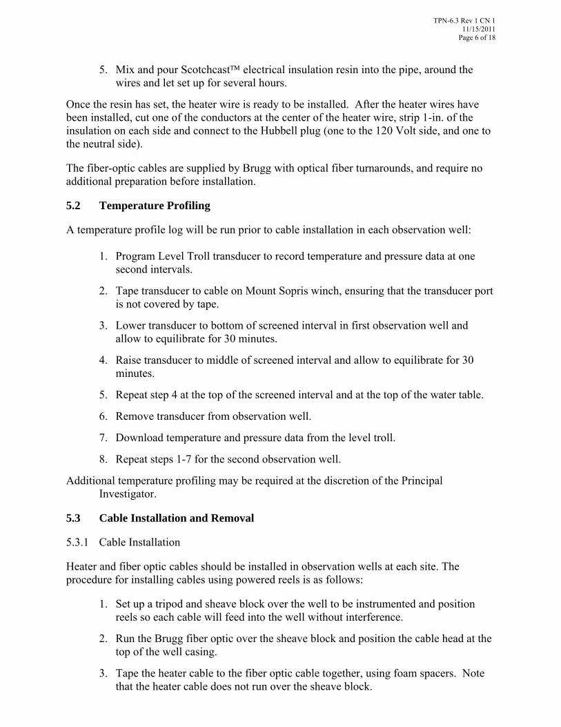
5. Mix and pour Scotchcast electrical insulation resin into the pipe, around the wires and let set up for several hours.
Once the resin has set, the heater wire is ready to be installed. After the heater wires have been installed, cut one of the conductors at the center of the heater wire, strip 1-in. of the insulation on each side and connect to the Hubbell plug (one to the 120 Volt side, and one to the neutral side).
The fiber-optic cables are supplied by Brugg with optical fiber turnarounds, and require no additional preparation before installation.
5.2 Temperature Profiling
A temperature profile log will be run prior to cable installation in each observation well:
1. Program Level Troll transducer to record temperature and pressure data at one second intervals.
2. Tape transducer to cable on Mount Sopris winch, ensuring that the transducer port is not covered by tape.
3. Lower transducer to bottom of screened interval in first observation well and allow to equilibrate for 30 minutes.
4. Raise transducer to middle of screened interval and allow to equilibrate for 30 minutes.
5. Repeat step 4 at the top of the screened interval and at the top of the water table.
6. Remove transducer from observation well.
7. Download temperature and pressure data from the level troll.
8. Repeat steps 1-7 for the second observation well.
Additional temperature profiling may be required at the discretion of the Principal Investigator.
5.3 Cable Installation and Removal
5.3.1 Cable Installation
Heater and fiber optic cables should be installed in observation wells at each site. The procedure for installing cables using powered reels is as follows:
1. Set up a tripod and sheave block over the well to be instrumented and position reels so each cable will feed into the well without interference.
2. Run the Brugg fiber optic over the sheave block and position the cable head at the top of the well casing.
3. Tape the heater cable to the fiber optic cable together, using foam spacers. Note that the heater cable does not run over the sheave block.
TPN-6.3 Rev 1 11/10/2011
Page 7 of 18
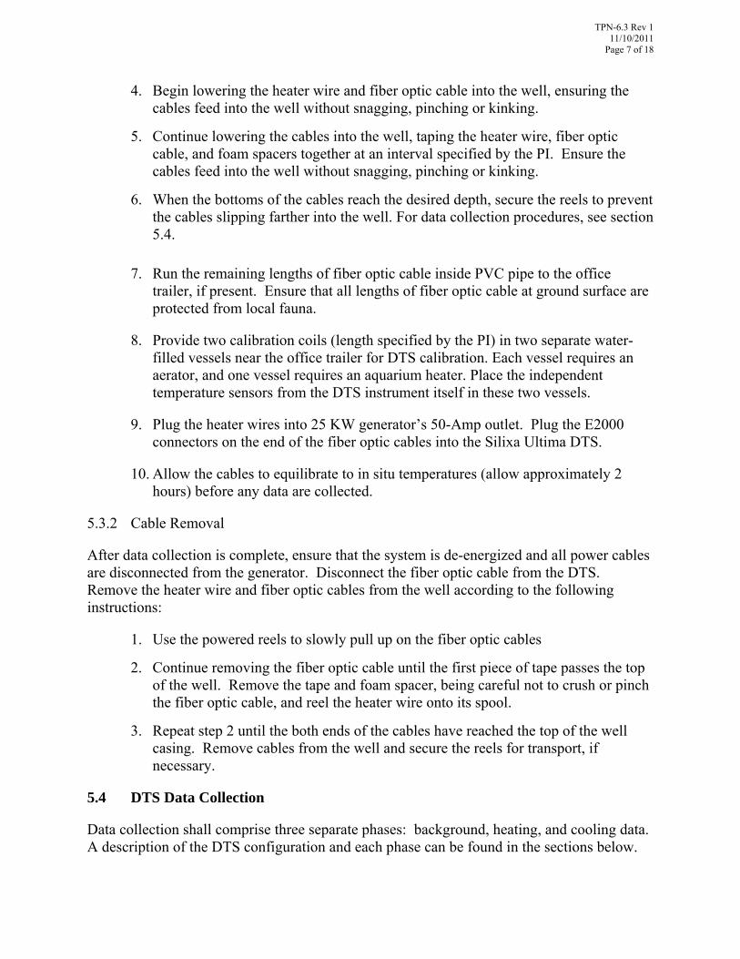
4. Begin lowering the heater wire and fiber optic cable into the well, ensuring the cables feed into the well without snagging, pinching or kinking.
5. Continue lowering the cables into the well, taping the heater wire, fiber optic cable, and foam spacers together at an interval specified by the PI. Ensure the cables feed into the well without snagging, pinching or kinking.
6. When the bottoms of the cables reach the desired depth, secure the reels to prevent the cables slipping farther into the well. For data collection procedures, see section 5.4.
7. Run the remaining lengths of fiber optic cable inside PVC pipe to the office trailer, if present. Ensure that all lengths of fiber optic cable at ground surface are protected from local fauna.
8. Provide two calibration coils (length specified by the PI) in two separate water-filled vessels near the office trailer for DTS calibration. Each vessel requires an aerator, and one vessel requires an aquarium heater. Place the independent temperature sensors from the DTS instrument itself in these two vessels.
9. Plug the heater wires into 25 KW generator’s 50-Amp outlet. Plug the E2000 connectors on the end of the fiber optic cables into the Silixa Ultima DTS.
10. Allow the cables to equilibrate to in situ temperatures (allow approximately 2 hours) before any data are collected.
5.3.2 Cable Removal
After data collection is complete, ensure that the system is de-energized and all power cables are disconnected from the generator. Disconnect the fiber optic cable from the DTS. Remove the heater wire and fiber optic cables from the well according to the following instructions:
1. Use the powered reels to slowly pull up on the fiber optic cables
2. Continue removing the fiber optic cable until the first piece of tape passes the top of the well. Remove the tape and foam spacer, being careful not to crush or pinch the fiber optic cable, and reel the heater wire onto its spool.
3. Repeat step 2 until the both ends of the cables have reached the top of the well casing. Remove cables from the well and secure the reels for transport, if necessary.
5.4 DTS Data Collection
Data collection shall comprise three separate phases: background, heating, and cooling data. A description of the DTS configuration and each phase can be found in the sections below.
TPN-6.3 Rev 1 11/15/2011
Page 8 of 18
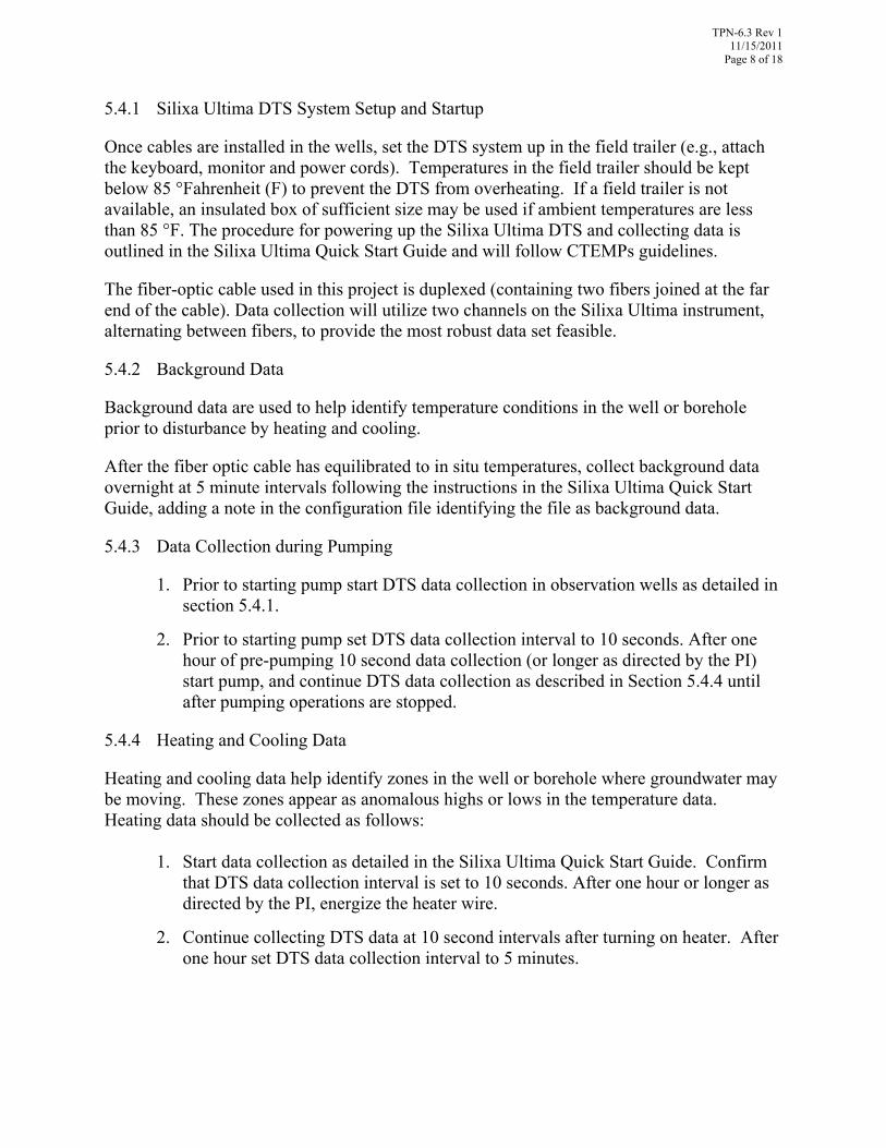
5.4.1 Silixa Ultima DTS System Setup and Startup
Once cables are installed in the wells, set the DTS system up in the field trailer (e.g., attach the keyboard, monitor and power cords). Temperatures in the field trailer should be kept below 85 °Fahrenheit (F) to prevent the DTS from overheating. If a field trailer is not available, an insulated box of sufficient size may be used if ambient temperatures are less than 85 °F. The procedure for powering up the Silixa Ultima DTS and collecting data is outlined in the Silixa Ultima Quick Start Guide and will follow CTEMPs guidelines.
The fiber-optic cable used in this project is duplexed (containing two fibers joined at the far end of the cable). Data collection will utilize two channels on the Silixa Ultima instrument, alternating between fibers, to provide the most robust data set feasible.
5.4.2 Background Data
Background data are used to help identify temperature conditions in the well or borehole prior to disturbance by heating and cooling.
After the fiber optic cable has equilibrated to in situ temperatures, collect background data overnight at 5 minute intervals following the instructions in the Silixa Ultima Quick Start Guide, adding a note in the configuration file identifying the file as background data.
5.4.3 Data Collection during Pumping
1. Prior to starting pump start DTS data collection in observation wells as detailed in section 5.4.1.
2. Prior to starting pump set DTS data collection interval to 10 seconds. After one hour of pre-pumping 10 second data collection (or longer as directed by the PI) start pump, and continue DTS data collection as described in Section 5.4.4 until after pumping operations are stopped.
5.4.4 Heating and Cooling Data
Heating and cooling data help identify zones in the well or borehole where groundwater may be moving. These zones appear as anomalous highs or lows in the temperature data. Heating data should be collected as follows:
1. Start data collection as detailed in the Silixa Ultima Quick Start Guide. Confirm that DTS data collection interval is set to 10 seconds. After one hour or longer as directed by the PI, energize the heater wire.
2. Continue collecting DTS data at 10 second intervals after turning on heater. After one hour set DTS data collection interval to 5 minutes.

TPN-6.3 Rev 1 11/15/2011
Page 9 of 18
3. Heating data should be collected for a minimum of 48 hours, at the discretion of the PI.
4. After 48 hours of data have been collected, de-energize the heater wire. One hour prior to turning off heater, set DTS data collection interval to 10 seconds. Continue 10 second data collection for one hour after start of cooling phase at which time set DTS data collection interval to 5 minutes for the remainder of the program. Collect cooling data for the same length of time as heating data were collected; and
5. After collection of heating and cooling data is complete, stop logging according to the Silixa Ultima Quick Start Guide.
5.4.5 Pressure Transducer Data
Downhole pressure data will be collected in the pumping well during pumping operations utilizing a Westbay SAM pressure transducer. Prior to logging, program the Westbay data logger to record pressure and temperature measurements at an interval specified by the PI. Note that multiple logging schedules may be used (e.g., every 10 seconds at the time the pump is started; every 1 minute during steady-state pumping).
5.5 Temperature Drift and Calibration Determination
Calibration of the DTS will follow standard CTEMPs recommended procedures for single ended measurements. During the entire experiment, two well mixed reference temperature baths will hold at least 20 meters of fiber optic cable each, and will be monitored with independent PT100 thermistors. The surface baths will consist of one ambient bath and one slightly heated bath (using a commercially available aquarium heater). It is not critical that the baths remain steady in temperature, only that they change temperature slowly in comparison to the monitoring interval, and are continuously monitored. Instrument drift, as well as any changes in the optical fiber properties can then easily be accounted for in the post-measurement calibration phase.
All raw data and calibration data will be submitted to the NWRPO Quality Assurance Records Center (QARC), in accordance with Quality Administrative Procedure 12.1, Control of Measuring and Test Equipment, along with any additional field data collected during calibration.
5.6 Data Processing
Data are recorded by the DTS in text format. The location of these files on the hard drive can be noted in the scientific notebook at the time of data collection. The name of each data file will, at a minimum, contain a well and zone designation. Additional information, such as date and time of measurement, may be included in the file name as well.

TPN-6.3 Rev 1 11/15/2011
Page 10 of 18
After a complete set of background, heating and cooling data has been collected, files are to be transferred to a computer and processed using both the manufacturer’s software and software available directly from CTEMPs for data collation, calibration and plotting.
6.0 PUMP OPERATIONS AND DATA COLLECTION
Prior to starting pump ensure that background DTS data has been collected overnight, that the DTS data collection interval has been set to 10 seconds, and that at least one hour of DTS data has been collected at a 10 second sampling interval. If DTS data collection was terminated after the background period be sure that data collection has restarted and that pressure data collection has commenced in the pumping well as described in Section 5.
Pumping and Sampling
1. Record the water meter volume in the scientific notebook.
2. Start the pump. The pump will run continuously during the entire 48 hour heating and 48 hour cooling periods.
3. After one hour of pumping during the heating phase change DTS data collection interval to 5 minutes.
4. Grab samples for bromide will be collected twice daily from 22S during pumping, or as directed by the PI. No samples will be collected during testing at 4PD. After the pump has run for approximately 1 hour in 22S, obtain a grab sample.
5. Collect grab water samples in pre-labeled 250-ml high-density polyethylene bottles (no chemical preservation required). Filter samples through 0.45 micron filters, cap the bottle, and place the sample in a cooler with blue ice. Store all samples on ice until delivered to the lab for analysis (laboratory information is shown below).
6. Copy and email pages from the scientific notebook for testing activities to the PI and Geoscience Manager at the end of each day of testing.
At the conclusion of testing, ship all samples to ACZ Laboratories in Steamboat Springs, Colorado. The address and contact information for ACZ is:
ACZ Laboratories, Inc. Attn: Tony Antalek
2773 Downhill Drive Steamboat Springs, CO 80487
800-334-5493 [email protected]

TPN-6.3 Rev 1 11/15/2011
Page 11 of 18
7.0 RECORDS
Data collected as part of this TPN are recorded electronically by the Silixa DTS and the Westbay and In-Situ dataloggers and are documented manually in the appropriate scientific notebook. All water sample chain-of-custody forms must be submitted to the QARC for archival. Data will be submitted, along with metadata describing their collection and limitations, to the NWRPO QARC for archival. Records in the QARC are available upon request.
8.0 REFERENCES
Independent Scientific Investigations Program Health and Safety Program, Site Specific Health and Safety Plan for General Field Activities.
Quality Administrative Procedure QAP-12.1, Control of Measuring and Test Equipment.
Silixa Ultima Quick Start Guide, Release Version 1.1 – August 2010.
Test Plan 7.0, Drill Site Management.
Test Plan 9.5. Natural Gradient Cross-Hole Tracer Test at Site 22.
Technical Procedure TP-10.0. Pumping/Injection Tests of Packed-Off Zones in Unscreened Open Boreholes or in Multiple Screen Boreholes with or without Observation Wells.
Work Plan WP-6, Early Warning Drilling Program Geophysical Logging Work Plan.
TPN-6.3 Rev 1 11/10/2011
Page 12 of 18
Figure 1 EWDP Well Locations

TPN-6.3 Rev 1 11/10/2011
Page 13 of 18
Nye County, Nevada
Early Warning Drilling Program
Well Completion Diagram
NC-EWDP-22S
Nuclear Waste Repository Project Office
Date: 9/20/02
Scale: none Drawn by: KJG
Ground Level
30 in. Nominal Borehole
6 5/8 in. OD Steel Well Casing
Screened Well Casing
Silica Sand (8/12 Mesh) /
Well Screen Sand (6/9 Mesh)
Transition Sand (16 Mesh)
Bentonite Grout ( 30%)
EXPLANATION
Granular Bentonite (8 Mesh)
Concrete Mix
SCREEN 1
18 in. OD Conductor Casing
75.1 ft
NOTE: (1) Screens are perforated casing with stainless steel wire wrap.(2) Indicated water level is approximate stabilized composite water level in developed well casing.
(42 in. /ft open area)
for surface completion detail see Wellhead Protection Diagram
481.2 ft
510.4 ft513.4 ft
586.3 ft590.1 ft
648.8 ft651.8 ft
766.5 ft770.6 ft
866.5 ft870.3 ft
986.9 ft991.0 ft
1127.5 ft1133.2 ft
1190.1 ft1196.5 ft
521.5 ft
581.3 ft
661.2 ft
760.6 ft
880.2 ft
SCREEN 2
SCREEN 3
SCREEN 4
980.0 ft
1140.0 ft
1180.0 ft
14 3/4 in. Nominal Borehole
Break in Scale
Geologist: JSW/KDD
(75.1 ft - 1196.5 ft)
(0 ft - 75.1 ft) (0 ft - 75.1 ft)
2
473 ft
(~2:1 by weight)
~ 65 ft
Figure 2 Completion Diagram for 22S

TPN-6.3 Rev 1 11/10/2011
Page 14 of 18
Nye County, Nevada
Early Warning Drilling Program
Well Completion Diagram
NC-EWDP-22PA
Nuclear Waste Repository Project Office
Date: 9/20/02
Scale: none Drawn by: KJG
Ground Level
2 in. Sch. 80 PVC Well Casing
Well Screen Sand (8/12 Mesh)
Bentonite Grout,
EXPLANATION
10 in. OD nominal borehole
47.3 ft
for surface completion detail see Wellhead Protection Diagram
3/8 in. hydrated chips
53.3 ft
147.4 ft153.6 ft
244.2 ft253.0 ft
280.9 ft
346.7 ft353.9 ft360.0 ft
445.7 ft455.0 ft466.2 ft
508.7 ft
587.0 ft
649.7 ft
Geologist: KDD
(0 ft - 368 ft)
50.4 ft
150.3 ft
250.3 ft
350.3 ft
451.2 ft
520.7 ft
579.7 ft
599.9 ft
661.5 ft
709.2 ft
759.8 ft770.0 ft
779.8 ft
Silica Sand (8/12 Mesh) /
(~2:1 by weight)
Unsaturated Zone Air Piezometer: 1 in. x 2 ft slotted ABS tubing with
5 7/8 in. OD nominal borehole(709.2 ft - 779.8 ft)
1/4 in. polyethylene tubing to surface
(368 ft - 709.2 ft)7 1/8 in. OD nominal borehole
471 ft
chips with Silica Sand (8/12 Mesh)Bentonite Grout, 3/8 in. hydrated
368.0 ft
6.5 ft
(0 ft - 6.5 ft)8 5/8 in. OD Protective Steel Casing
Well Screen: 0.02 in. slots,9.5 in. /ft open area
Note: Indicated water level is approximate open hole water level at end of drilling.
Granular Bentonite (8 Mesh)
Figure 3 Completion Diagram for 22PA
TPN-6.3 Rev 1 11/10/2011
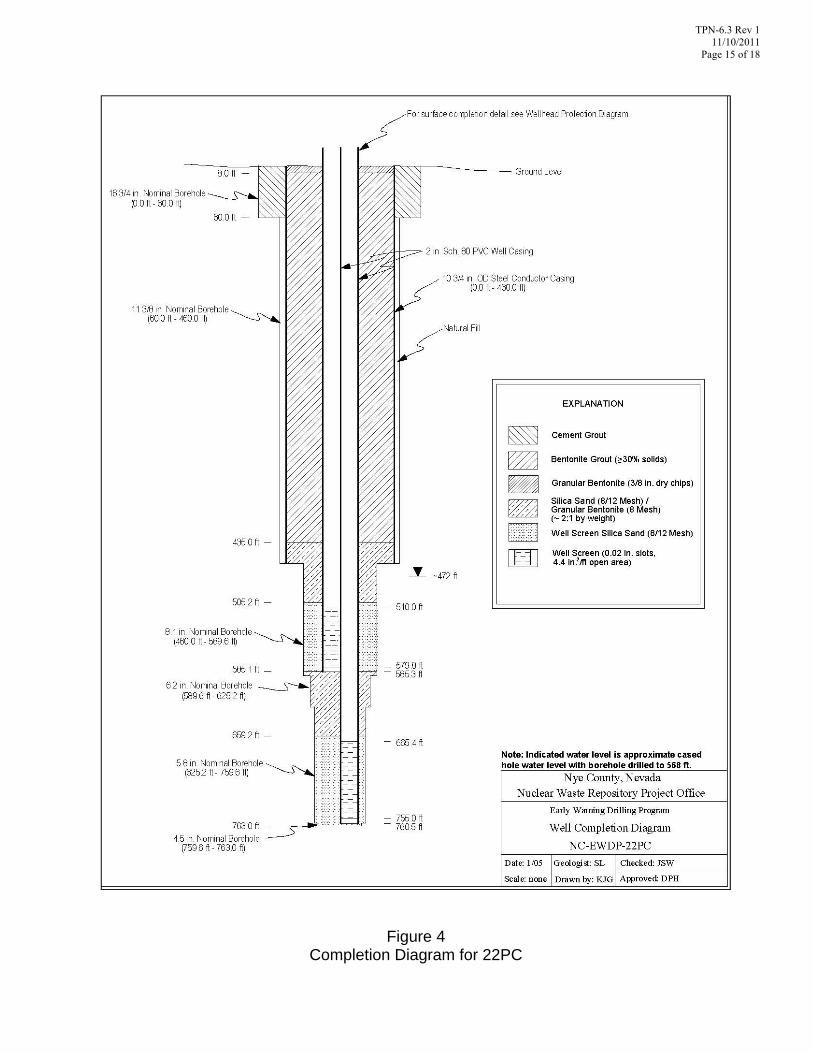
Page 15 of 18
Figure 4 Completion Diagram for 22PC

TPN-6.3 Rev 1 11/10/2011
Page 16 of 18
Figure 5 Completion Diagram for 4PD

TPN-6.3 Rev 1 11/10/2011
Page 17 of 18
Figure 6 Completion Diagram for 4PA
TPN-6.3 Rev 1 11/10/2011
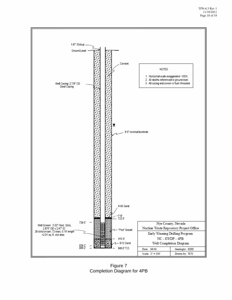
Page 18 of 18
Figure 7 Completion Diagram for 4PB