pumplab book 4 preview
TRANSCRIPT
8/12/2019 PumpLab Book 4 Preview
http://slidepdf.com/reader/full/pumplab-book-4-preview 1/14
Understanding
Process Control
BOOK
Turbine Technologies, Ltd., 410 Phillips Street, Chetek, WI, 54728 USA.Phone: 715-924-4876, Fax: 715-924-2436, www.turbinetechnologies.com
4 Lab Work

8/12/2019 PumpLab Book 4 Preview
http://slidepdf.com/reader/full/pumplab-book-4-preview 2/14
2UNDERSTANDING PROCESS CONTROL
Copyright © 2013 by Turbine Technologies, Ltd.
BOOK 4: Understanding Process Control - Lab Work
EVALUA ION COPY
INTRODUCTION
Upon completion of this book, the student will have a solid, hands-on experience running the centrifugal pumping
system in Process Control Mode. Students will be able to choose a pressure or ow attribute to maintain in the pro-
cess system and devise a Proportional, Integral and Derivative (PID) Gain scenario that will optimize the system to
maintain that attribute during disruptions in the system. e student will test their PID scenario to determine how
much disruption the system can endure before it fails its mission to maintain the required pressure or ow value.
Turbine Technologies, Ltd., LabVIEW, National Instruments are trademarks of respective systems and equipment used in equipment
manufactured by Turbine Technologies, Ltd.
Copyright 2013 by Turbine Technologies, Ltd.
All rights reserved. No part of this lesson series may be reproduced, translated or transmitted in any form or by any means without
the permission of Turbine Technologies, Ltd.
Turbine Technologies, Ltd., 410 Phillips Street, Chetek, WI, 54728 USA.
Phone: 715-924-4876, Fax: 715-924-2436, www.turbinetechnologies.com
8/12/2019 PumpLab Book 4 Preview
http://slidepdf.com/reader/full/pumplab-book-4-preview 3/14
3UNDERSTANDING PROCESS CONTROL
Copyright © 2013 by Turbine Technologies, Ltd.
BOOK 4: Understanding Process Control - Lab Work
TABLE OF CONTENTS
Book 4: Understanding Process Control - Lab Work
Lesson 1: Process Control Virtual Instrument Panel Tour.........................................................................4
Focus 1: Starting Up the Data Computer
Focus 2: Virtual Tour of Instrument Panel
Knowledge Certification Quiz: Lesson 1
Lesson 2: Data Gathering for Trial and Error Method...............................................................................7
Focus 1: Maintaining a Constant Flow Setting
Knowledge Certification Quiz: Lesson 2, Focus 1
Focus 2: Maintaining a Constant Pressure Setting
Knowledge Certification Quiz: Lesson 2, Focus 2
Lesson 3: Ziegler-Nichols Programming Method .....................................................................................21
Focus 1: Maintaining a System Flow of 30 GPM
Focus 2: Maintaining a System Pressure of 5 PSIG
Knowledge Certification Quiz: Lesson 3
8/12/2019 PumpLab Book 4 Preview
http://slidepdf.com/reader/full/pumplab-book-4-preview 4/14
4UNDERSTANDING PROCESS CONTROL
Copyright © 2013 by Turbine Technologies, Ltd.
BOOK 4: Understanding Process Control - Lab Work
Lesson 1: Process Control Virtual Instrument Panel Tour
e goal of this lesson is to finish the introduction of the PumpLabTM Virtual Instrument Panel covered in Book 2,
by introducing the Process Control features.
Focus 1: Starting Up the Data Computer
1. Verify that the PumpLab is connected to an electrical power source.
2. Verify that data computer is connected via USB cable to the USB outlet in the PumpLab.
3. With the PumpLab OFF, turn the computer ON and let it fully boot up.
4. Turn ON the PumpLab MASTER Power Switch. Give it a few seconds to get itself set.
5. Double click the PumpLab Icon on the computer screen to load the PumpLab Virtual Instrument Panel.
6. Verify that PumpLab is primed (pipes filled with water). If not, follow priming procedure in Operators Manual.
7. e system is now ready to use.
8. IF PROCEDURE WAS NOT FOLLOWED AND AN ERROR IS DISPLAYED, power down computer andPumpLab and try again.
Focus 2: Virtual Tour of Instrument Panel
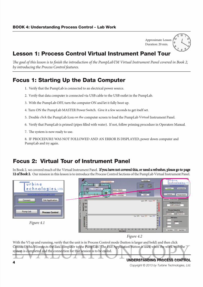
In Book 2, we covered much of the Virtual Instrument Panel. If you have not covered this, or need a refresher, please go to page12 of Book 2. Our mission in this lesson is to introduce the Process Control Sections of the PumpLab Virtual Instrument Panel.
With the VI up and running, verify that the unit is in Process Control mode (button is larger and bold) and then clickConnect, which connects the data computer to the PumpLab. e Exit Application button is used when the work with the
system is completed and the connection for that session is to be ended.
Figure 4.1
Figure 4.2
Approximate Lesson
Duration: 20 min.
8/12/2019 PumpLab Book 4 Preview
http://slidepdf.com/reader/full/pumplab-book-4-preview 5/14
5UNDERSTANDING PROCESS CONTROL
Copyright © 2013 by Turbine Technologies, Ltd.
BOOK 4: Understanding Process Control - Lab Work
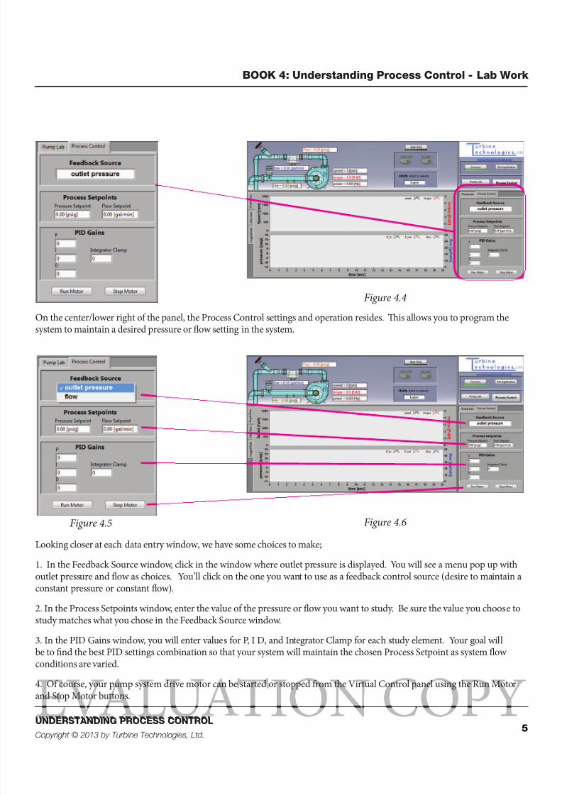
Figure 4.4
On the center/lower right of the panel, the Process Control settings and operation resides. is allows you to program thesystem to maintain a desired pressure or flow setting in the system.
Figure 4.5 Figure 4.6
Looking closer at each data entry window, we have some choices to make;
1. In the Feedback Source window, click in the window where outlet pressure is displayed. You will see a menu pop up withoutlet pressure and flow as choices. You’ll click on the one you want to use as a feedback control source (desire to maintain aconstant pressure or constant flow).
2. In the Process Setpoints window, enter the value of the pressure or flow you want to study. Be sure the value you choose tostudy matches what you chose in the Feedback Source window.
3. In the PID Gains window, you will enter values for P, I D, and Integrator Clamp for each study element. Your goal willbe to find the best PID settings combination so that your system will maintain the chosen Process Setpoint as system flowconditions are varied.
4. Of course, your pump system drive motor can be started or stopped from the Virtual Control panel using the Run Motor
and Stop Motor buttons.
8/12/2019 PumpLab Book 4 Preview
http://slidepdf.com/reader/full/pumplab-book-4-preview 6/14
6UNDERSTANDING PROCESS CONTROL
Copyright © 2013 by Turbine Technologies, Ltd.
BOOK 4: Understanding Process Control - Lab Work
Knowledge Certification Quiz: Lesson 1
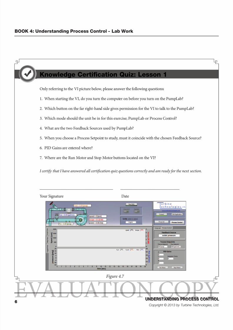
Only referring to the VI picture below, please answer the following questions:
1. When starting the VI, do you turn the computer on before you turn on the PumpLab?
2. Which button on the far right-hand side gives permission for the VI to talk to the PumpLab?
3. Which mode should the unit be in for this exercise; PumpLab or Process Control?
4. What are the two Feedback Sources used by PumpLab?
5. When you choose a Process Setpoint to study, must it coincide with the chosen Feedback Source?
6. PID Gains are entered where?
7. Where are the Run Motor and Stop Motor buttons located on the VI?
I certify that I have answered all certification quiz questions correctly and am ready for the next section.
____________________________________ _____________________________
Your Signature Date
Figure 4.7
8/12/2019 PumpLab Book 4 Preview
http://slidepdf.com/reader/full/pumplab-book-4-preview 7/14
7UNDERSTANDING PROCESS CONTROL
Copyright © 2013 by Turbine Technologies, Ltd.
BOOK 4: Understanding Process Control - Lab Work
Lesson 2: Data Gathering for Trial and Error Method
In books 1 & 2 we studied the pump performance characteristics. Now in Process Control, we’re going to use those
characteristics and apply them towards maintaining a system pressure or flow setting and seeing how the PumpLab
System automatically responds when system inputs are changed rapidly.
Focus 1: Maintaining a Constant Flow Setting
Let’s say our pump system must maintain a system Flowrate of 30 GPM. Let’s figure out how to set up the system to that it willdo that, even if the system is disrupted. What do we mean disrupted? In our case, we started closing inlet or outlet valves togive us changes in flow/pressure in the system.
Approximate Lesson
Duration: 2 Hours
A pump system operating in a process plant may be set up to maintain a particular flow or pressure setting so that the processcan be successfully executed. When everything is running smoothly and steadily, there usually are no problems doing this.However, if something in the system causes a disruption (maybe supply flow is increasing/decreasing or the system is backingup and elevating system pressure), the pump system must react automatically and accurately by either raising or lowering itsspeed.
In order to set up a system to maintain a desired Flowrate or Pressure while responding adequately to disruptions in the flowcircuit, proper Proportional, Integral and Derivative Gains must be identified and programmed into the system.
We discussed a few different ways to do this in Book 3;
1.Trial and Error Method
2. Ziegler-Nichols Method
3. Factory Programming Soware
We will start off by using a Trial and Error Method utilizing the Gold Impeller. ese same procedures can be used for the redand black impellers as well.
8/12/2019 PumpLab Book 4 Preview
http://slidepdf.com/reader/full/pumplab-book-4-preview 8/14
8UNDERSTANDING PROCESS CONTROL
Copyright © 2013 by Turbine Technologies, Ltd.
BOOK 4: Understanding Process Control - Lab Work
EVALUA ION COPY
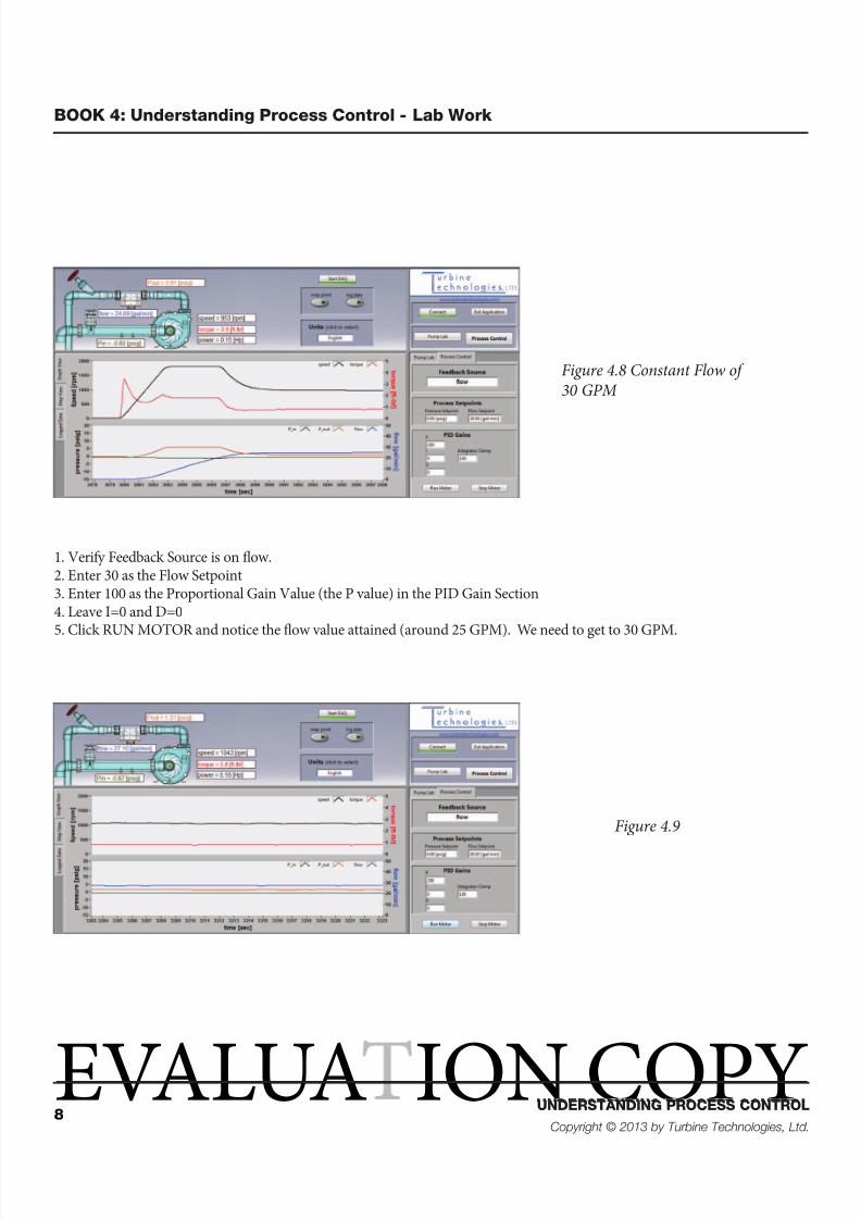
Figure 4.8 Constant Flow of30 GPM
Figure 4.9
1. Verify Feedback Source is on ow.2. Enter 30 as the Flow Setpoint3. Enter 100 as the Proportional Gain Value (the P value) in the PID Gain Section4. Leave I=0 and D=05. Click RUN MOTOR and notice the ow value attained (around 25 GPM). We need to get to 30 GPM.
8/12/2019 PumpLab Book 4 Preview
http://slidepdf.com/reader/full/pumplab-book-4-preview 9/14
9UNDERSTANDING PROCESS CONTROL
Copyright © 2013 by Turbine Technologies, Ltd.
BOOK 4: Understanding Process Control - Lab Work
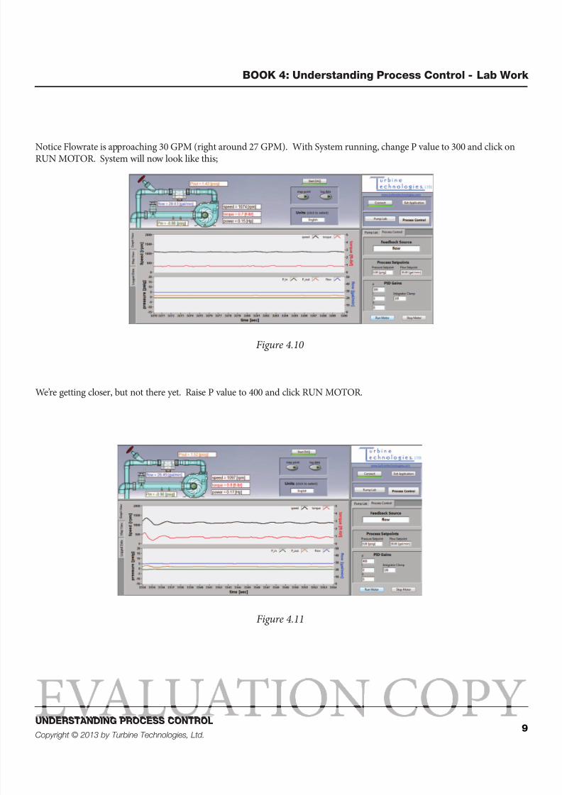
Notice Flowrate is approaching 30 GPM (right around 27 GPM). With System running, change P value to 300 and click onRUN MOTOR. System will now look like this;
Figure 4.10
We’re getting closer, but not there yet. Raise P value to 400 and click RUN MOTOR.
Figure 4.11
8/12/2019 PumpLab Book 4 Preview
http://slidepdf.com/reader/full/pumplab-book-4-preview 10/14
10UNDERSTANDING PROCESS CONTROL
Copyright © 2013 by Turbine Technologies, Ltd.
BOOK 4: Understanding Process Control - Lab Work
EVALUA ION COPY
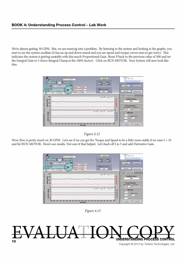
We’re almost getting 30 GPM. But, we are running into a problem. By listening to the system and looking at the graphs, youstart to see the system oscillate (it has an up and down sound and you see speed and torque curves start to get wavy). isindicates the system is getting unstable with this much Proportional Gain. Reset P back to the previous value of 300 and setthe Integral Gain to 5 (leave Integral Clamp at the 100% factor). Click on RUN MOTOR. Your System will now look likethis:
Figure 4.12
Wow, flow is pretty much on 30 GPM. Let’s see if we can get the Torque and Speed to be a little more stable if we raise I = 10and hit RUN MOTOR. Here’s our results. Not sure if that helped. Let’s back off I to 5 and add Derivative Gain.
Figure 4.13

8/12/2019 PumpLab Book 4 Preview
http://slidepdf.com/reader/full/pumplab-book-4-preview 11/14
11UNDERSTANDING PROCESS CONTROL
Copyright © 2013 by Turbine Technologies, Ltd.
BOOK 4: Understanding Process Control - Lab Work
Let’s try a Derivative Gain of 50 just to see if it makes the process even more stable. It seems OK; let’s try D=75.
Figure 4.14
It hasn’t improved the stability; in fact it may have gotten a little more wavy. Consequently, return D to 50 and we’ll considerthis system optimized based on this particular Trial and Error methodology.
Figure 4.15
8/12/2019 PumpLab Book 4 Preview
http://slidepdf.com/reader/full/pumplab-book-4-preview 12/14
12UNDERSTANDING PROCESS CONTROL
Copyright © 2013 by Turbine Technologies, Ltd.
BOOK 4: Understanding Process Control - Lab Work
EVALUA ION COPY
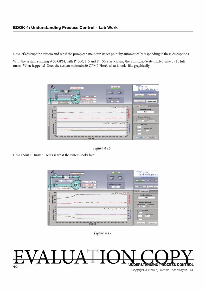
Now let’s disrupt the system and see if the pump can maintain its set point by automatically responding to these disruptions.
With the system running at 30 GPM, with P=300, I=5 and D =50, start closing the PumpLab System inlet valve by 10 fullturns. What happens? Does the system maintain 30 GPM? Here’s what it looks like graphically:
Figure 4.16
How about 15 turns? Here’s is what the system looks like:
Figure 4.17
8/12/2019 PumpLab Book 4 Preview
http://slidepdf.com/reader/full/pumplab-book-4-preview 13/14
13UNDERSTANDING PROCESS CONTROL
Copyright © 2013 by Turbine Technologies, Ltd.
BOOK 4: Understanding Process Control - Lab Work
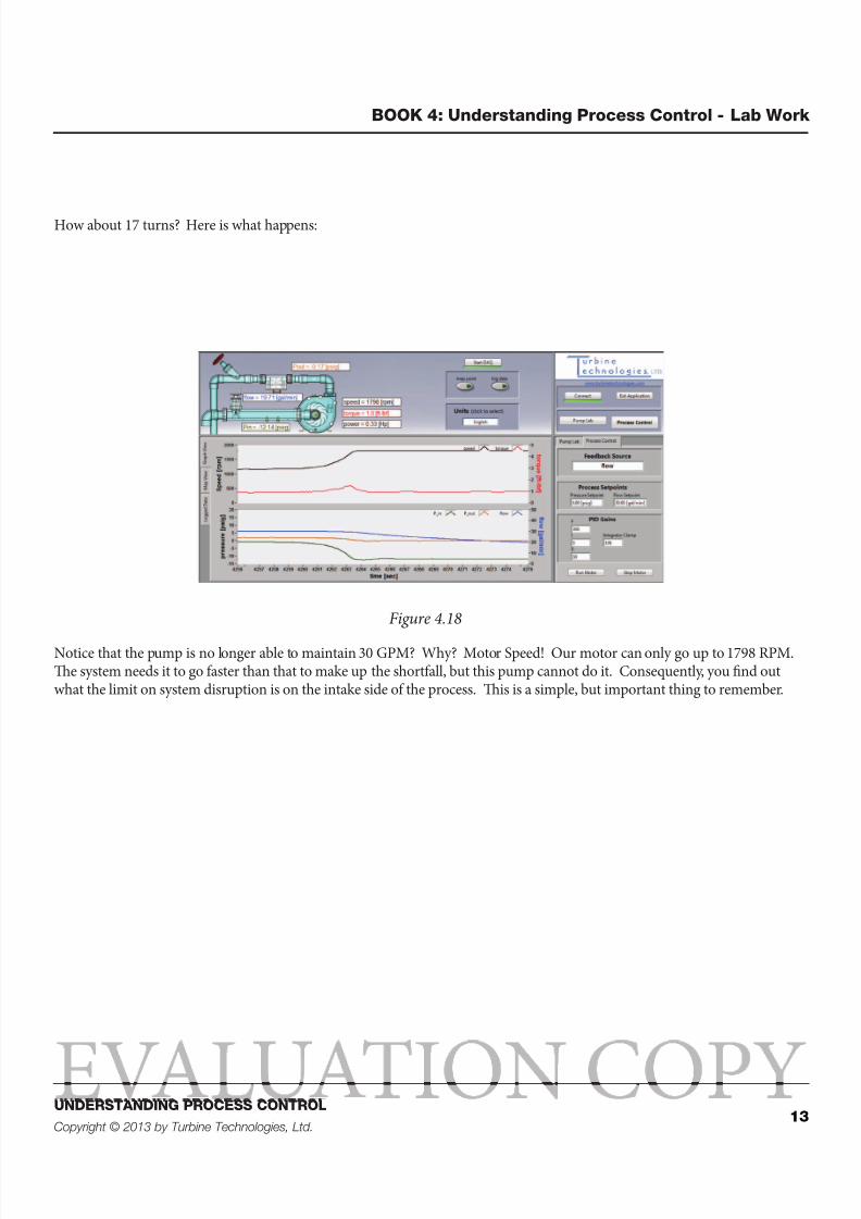
How about 17 turns? Here is what happens:
Figure 4.18
Notice that the pump is no longer able to maintain 30 GPM? Why? Motor Speed! Our motor can only go up to 1798 RPM.e system needs it to go faster than that to make up the shortfall, but this pump cannot do it. Consequently, you find outwhat the limit on system disruption is on the intake side of the process. is is a simple, but important thing to remember.

8/12/2019 PumpLab Book 4 Preview
http://slidepdf.com/reader/full/pumplab-book-4-preview 14/14
14UNDERSTANDING PROCESS CONTROL
Copyright © 2013 by Turbine Technologies, Ltd.
BOOK 4: Understanding Process Control - Lab Work
EVALUA ION COPY
Knowledge Certification Quiz: Lesson 2, Focus 1
1. Based on a Trial and Error Methodology, devise a stable PID gain setting to allow the pump system tomaintain a 40 GPM ow rate.
2. Once the rst task was established, how far you can turn the inlet and then outlet valves (each startingfrom system in full flow mode operation) before system cannot maintain the desired flow rate?Assess your performance range.
I certify that I have answered all certification quiz questions correctly and am ready for the next section.
____________________________________ _____________________________
Your Signature Date