pure competence in air. novenco car park thrust ventilation system description€¦ · ·...
TRANSCRIPT

NOVENCO CAR PARKTHRUST VENTILATION SYSTEM DESCRIPTION
Pure competence in air.

PREFACEGROWING NEEDCars have become a natural part of everyday life. Despite wide-spread public transport systems, most people nowadays own a car. Parking facilities are therefore in great demand, particularly in cities and large towns. Conventional, open car parks take up far too much space, while people tend to prefer parks and open spaces in their cities. In other situations, such as climate conditions or a desire to pre-vent parked cars from being vandalized necessitate closed parking facilities. Therefore, more and more car parks are being built, both below and above ground.
AIR MOVEMENT
NOVENCO CAR PARK VENTILATION SYSTEMFor many years, NOVENCO has supplied fans for road tunnels, and their design and further development have often taken place in close cooperation with the authorities. Since 1994, NOVENCO has put this experience to use in car parks.
VENTILATIONVentilation is the transport of air. To transport air a mass must be moved. At 20° C, the density of air is approx. 1.2 kg/m3.Ventilating 10 m3 air therefore involves moving a mass of 12 kg. Air can be moved in three ways. The best known method is to transport it through ducting by means of a fan that either sucks or pushes the air through the duct. It is also well known that air moves vertically in response to thermal differentials.
The third method is known as jet ventilation and utilises the fact that a moving body changes velocity when it is subjected to a “pushing force”. In physics, this phenomenon is known as thrust. On the basis of continuous testing, the use of jet ventilation has been optimised and integrated into car park safety systems. This brochure provides information on the possibilities provided by jet ventilation.
2
CAR PARK CATEGORIESRegarding ventilation systems, there are two types of car parks: open and enclosed car parks. Even car parks which are situated above ground can be an enclosed car park if there is insufficient natural ventilation.
OPEN CAR PARKSOpen car parks include uncovered car parks and those that are sufficiently open to ensure the necessary ventilation. Several requirements must be met before a car park is classified as being open. Each country has its own regulations, which may be more or less stringent. Generally, requirements are more specific in countries with a longer tradition of building car parking facilities and thus more experience in their design.
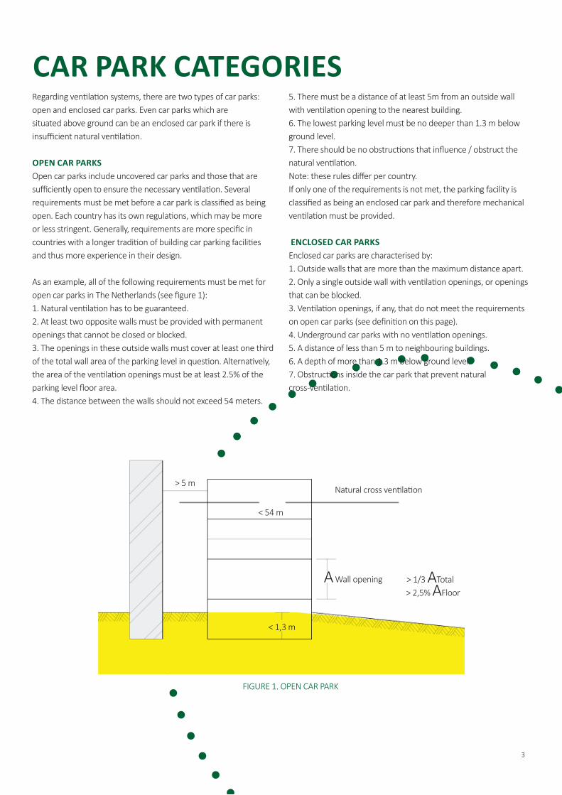
As an example, all of the following requirements must be met for open car parks in The Netherlands (see figure 1):1. Natural ventilation has to be guaranteed.2. At least two opposite walls must be provided with permanent openings that cannot be closed or blocked.3. The openings in these outside walls must cover at least one third of the total wall area of the parking level in question. Alternatively, the area of the ventilation openings must be at least 2.5% of the parking level floor area.4. The distance between the walls should not exceed 54 meters.
5. There must be a distance of at least 5m from an outside wall with ventilation opening to the nearest building.6. The lowest parking level must be no deeper than 1.3 m below ground level.7. There should be no obstructions that influence / obstruct the natural ventilation.Note: these rules differ per country.If only one of the requirements is not met, the parking facility is classified as being an enclosed car park and therefore mechanical ventilation must be provided.
ENCLOSED CAR PARKSEnclosed car parks are characterised by:1. Outside walls that are more than the maximum distance apart.2. Only a single outside wall with ventilation openings, or openings that can be blocked.3. Ventilation openings, if any, that do not meet the requirements on open car parks (see definition on this page).4. Underground car parks with no ventilation openings.5. A distance of less than 5 m to neighbouring buildings.6. A depth of more than 1.3 m below ground level.7. Obstructions inside the car park that prevent natural cross-ventilation.
FIGURE 1. OPEN CAR PARK
3
> 5 m
< 54 m
< 1,3 m
Natural cross ventilation
A Wall opening > 1/3 ATotal > 2,5% AFloor

CONVENTIONAL VENTILATIONPresently, four different ventilation methods are used in car parking facilities.
NATURAL VENTILATIONNatural ventilation by means of wind and thermal conditions is used in open car parks.
SEMI-NATURAL VENTILATIONIn this case the supply air will enter the car park naturally and the air will be exhausted mechanically. The opposite is also possible. The air will be supplied mechanically and the exhaust air will leave the car park by overpressure. With this method, ducts are generally not necessary.
SIMPLE CONVENTIONAL VENTILATIONSimple conventional ventilation is used in closed car parks. Such systems also consist of fresh-air fans and exhaust fans, but no ducts are used.
CONVENTIONAL VENTILATION Conventional ventilation is used in closed car parks. It consists of both fresh-air fans and exhaust fans in combination with ducts for transporting air.
In practice, there are several problems with conventional ventila-tion systems.
For example:• There is no or insufficient room for inlet and/or exhaust ducts.• There is no guarantee that the system will provide sufficient ventilation.• So-called “dead” corners with little or no ventilation are likely.• There is no room for ducts.• Smoke control in case of fire is not considered during system design.• The possibility of regulating the level of ventilation in response to variable requirements is not considered.• Fire protection installations such as fire doors and fire walls prevent an unobstructed view of the car park.
NOVENCO jet ventilation systems can be adapted to cover the needs for CO ventilation and, in special circumstances, smoke control in case of fire.
FIGURE 2. SEMI-NATURAL VENTILATION
FIGURE 3. MECHANICAL VENTILATION
Top viewSide view
FIGURE 4. CONVENTIONAL VENTILATION DUCTS
4

In conventional ventilation systems, all air is drawn through fans and ducting. This applies to both the fresh air supplied and the discharged spent air. To prevent pressure drop, air velocity is kept as low as possible. However, this means that ducts must be rela-tively wide, thus requiring considerable space.The function of jet fans is based on the impulse principle. From a small surface area (fan outlet) air is discharged at a relatively high velocity. When this air collides with the air in front of the fan, it thrusts the air forwards while at the same time drawing the sur-rounding air along with it (induction effect). Therefore the surrounding air will be moved in the direction of the airflow. As a result of this induction or entrainment, the quantity of air in motion will always be considerably larger than the quantity of air passing through the fan itself.This driving force is called the thrust or impulse force of the jet fans and is expressed in Newton [N]. The thrust is the product of the mass flow rate and the change in velocity. Thrust is the unit of measurement for jet fans, in contrast to conventional fans where output is measured in volume flow [m³/s] and pressure [Pa]. In theory, assuming that the surrounding air has zero initial velocity, the thrust generated by a jet fan is equal to the product of the volu-metric air flow rate, density and the outlet velocity of the jet fan.
The influence of the jet fans on the surrounding air is only local. The effective working area of the jet fans is depending on the type and function of the ventilation system. Jet fans are placed at strategic positions to ensure air movement and mixing throughout the car park. The combination of this thrust ventilation principle with mechanical exhaust and (natural and/or mechanical) fresh air supply results in an optimal ventilation system for enclosed car parks. In car parking facilities, jet fans can be used to replace ducts for the extraction of both CO and eventually (explosive) liquid petrol gas fumes.The presence of CO in a car park indicates that other hazardous fumes (e.g. benzene) are also present. As a result of this, the German authorities have reduced the limits for CO in car parking facilities from 100 ppm to 50-60 ppm, depending on the federal state in question.
Figure 9 illustrates the possible design of a closed system consisting of jet fans and supply- and exhaust fans installed in a shaft.
DUCTLESS VENTILATION SYSTEM
FIGURE 5A. NO AVAILABLE SPACE FOR VENTILATION DUCTS
FIGURE 5B. JET FANS POSITIONED BETWEEN GIRDERS
FIGURE 6. INDUCTION EFFECT OF A JET FAN
FIGURE 7. JET VENTILATION PRINCIPLE
Top view
Side view
5

DUCTLESS VENTILATION SYSTEMThe extraction unit typically consists of a grille, two exhaust fans and, if necessary, sound attenuation.
When for example the set limit for CO is exceeded, a signal is sent from the gas detection system to the main control panel. In the PLC (Programmable Logic Control) the associated ventilation scenario is started, which controls the correct setting of (shaft) dampers, starting the exhaust fans, followed by the supply fans and jet fans.
A ventilation system with jet fans offers numerous advantages over conventional ducted ventilation systems for car parks:• Space saving; the function of complex ductwork in the car park, taking up valuable space which is already restricted, is replaced by jet fans.
• Flexible installation; positioning of the jet fans is very flexible and can easily be coordinated with other systems within the car park.• Optimal ventilation; because the jet fans efficiently mix the exhaust fumes with the surrounding air, high local concentrations of toxic gases are prevented.• No dead spots; because jet fans can be placed in parts of the car park with limited ventilation, the build-up of high local concentra-tions are prevented.• Energy savings; compared with ventilation systems with ductwork, relevant energy savings can be achieved. • Cost savings; during design and installation the (re-)positioning of the jet fans is very flexible.• Smoke control systems are possible.
In open car parks where no ventilation is required, natural ventila-tion can be supported by jet fans, thus preventing the occurrence of “dead” areas. The same applies to parking facilities that only just fail to meet the requirements on open car parks. Here too, requirements for natu-ral ventilation can often be met using jet fans alone. In such cases it is often best to use 100% reversible NOVENCO fans. These fans are capable of providing the same thrust in either direction so that the direction of flow can be changed to suit wind conditions.
FIGURE 8. TYPICAL JET FAN SYSTEM
6
In Europe, almost every country has their own standards and guidelines for smoke ventilation systems in car parks. In the European Union, there is currently a draft European Standard on the design of Smoke Control Systems. Taking the British Standard BS 7346 part 7 (2006) as a starting point, car park ventilation systems can be designed for one or more of three objectives in the event of a fire:1. Assist fire-fighters to clear smoke from a car park during and after a fire;2. Provide clear smoke-free access for fire-fighters to a point close to the seat of the fire;3. Protect the means of escape from the car park.With regard to objective 3 it must be noted that the ceiling height for an average car park is only 2,5 – 3,0 m and therefore the height of an eventual smoke free layer is only very limited.Depending on the design objective, the car park smoke ventilation system has to be designed as: 1. Smoke clearance systems (objective 1);2. Smoke control systems (objective 2);
SMOKE CLEARANCE SYSTEMSSmoke clearance systems are intended to provide ventilation to allow speedier clearance of the smoke once the fire has been extin-guished. The ventilation might also help reduce smoke density and temperature during the course of a fire.Smoke clearance systems are not engineered solutions. This means that the smoke extract rate is provided in standards, guidelines or the building regulations. In most European countries a mini-mum smoke ventilation rate per fire compartment of 10 air changes per hour is required:
Qv = ACH x Vc (1) Vc = Ac x hc (2)Where:
Vc : volume car park / fire compartment [m³]Ac : floor area [m²]hc : height [m]Qv : required smoke ventilation extract [m³/h]ACH : air changes per hour [h-1]
These systems are designed for objective 1 of the BS 7346 part 7 and are therefore not specifically intended to maintain any area of a car park clear of smoke, to limit smoke density or temperature to within any limits.To avoid smoke circulation and descent of the smoke layer during evacuation (objective 3), it might be preferable to either delay operation of the jet fans after automatic actuation or to provide only manual actuation from a fire service override switch.
SMOKE CONTROL SYSTEMSSmoke control systems are provided specifically in order to assist fire-fighters to carry out fire-fighting operations. Due to the low heights in car parks vertical smoke control with a smoke-free layer is not possible. Therefore, in a car park smoke control is horizontal rather than vertical. The system is designed to operate automatically in case of a fire detection and ensures clear, smoke-free access by fire-fighters to a point close to the seat of the fire. Primarily, such systems will assist fire-fighting by:1. Detecting the origin of the fire to a specific location in the car park;2. Moving the smoke and heat from that location to-wards a specific extraction point or points;3. Creating a smoke free approach zone or bridgehead clear of the fire. This allows fire-fighters to assemble personnel and equipment in favorable conditions and fire-fighting operations to be carried out more quickly, safely and efficiently.
The basis of the design of a smoke control system is to prevent the smoke from back layering against the ventilation airflow by maintaining a critical air velocity. This minimum critical velocity is dependent on a number of factors, due to which smoke control systems are always fire engineered solutions:
1. What is the maximum fire size?2. Is there a sprinkler system to limit the fire size?3. What if the fire spreads to other cars?4. Where are the escape / evacuation routes?5. How long will it take to evacuate the car park?6. What is the reaction time of the fire brigade?7. Where are the attack routes for the fire brigade?8. Where can smoke extract and air supply be planned?
In large or complex car parks where jet fans are employed, there might be multiple extraction points. Smoke control systems can be designed to be fully reversible to move the smoke in one of several directions, depending on the location of the fire. Again it is important to ensure that there are suitably located fire-fighting access points to allow the bridgehead to be created for each design fire scenario considered.
SMOKE VENTILATION SYSTEM
7

SMOKE VENTILATION SYSTEM
FIGURE 9A. TOP VIEW OF A SMOKE CONTROL SYSTEM (OBJECTIVE 2)
FIGURE 9B. SIDE VIEW OF A SMOKE CONTROL SYSTEM (OBJECTIVE 2)
To protect the means of escape from the car park, it is advisable that upon fire detection only the main extractors and supply are put into operation. This will not disrupt the stratification despite a portion of the smoke gases being extracted quickly. Therefore, jet fans should always be switched off during this evacuation period to avoid smoke circulation and cooling and thus the descent of the smoke layer into the occupied space. Once the jet fans have been switched on, the smoke will quickly spread to the downstream section.
Although the jet fans change the velocity distribu-tion they are only of limited (local) influence on the main airflow through the car park. This main average airflow is to a significant degree deter-mined by the smoke extract rate of the main extrac fans in combination with the makeup air intakes. Through induction and mixing, the jet fans provide a considerable reduction in smoke temperatures. By reducing the smoke tem-peratures, the level of smoke back layering against the ventilation airflow can be reduced, providing the fire brigade with improved conditions for firefighting. The increased airflow with smoke control will not increase the fire size since it is limited by the fuel, which is the material from the burning car. Inside the car park there is enough oxygen available to feed the fire. In 1998 NOVENCO has proven the method of smoke control system with full-scale fire tests in a car park in Amsterdam. During these fire tests in total 18 passenger cars were burned by an independent body (TNO – Organization for Applied Scientific Research) commis-sioned by the fire brigades and Dutch ministries.
FIGURE 10. VIEW OF THE SEAT OF THE FIRE WITH SMOKE CONTROL
8
FIGURE 9C. SIDE VIEW OF A SMOKE CLEARANCE SYSTEM (OBJECTIVE 1)

Conclusions of the tests were:• Conventional duct-based ventilation systems are unsuitable for smoke control purposes, even with air change rates of 10 times per hour. The entire area quickly becomes filled with smoke and locating the fire is very difficult.• Smoke control is possible with engineered solutions with high smoke exhaust rates based on critical air velocity over the fire in combination with active cooling of the smoke with jet fans.• During the evacuation period, the jet fans must be switched off to prevent mixing of air and smoke.• By running the exhaust, supply and jet fans at full speed after evacuation is complete, the spread of smoke can be kept within a limited area. The fire also remains visible at all times.• Fire development can be observed during the entire extinguish-ing process, providing improved safety for the firefighters and faster fire extinction.• Smoke control systems can effectively cool down the smoke by mixing smoke with surrounding (cold) air.• After extinction, visibility within the car park will quickly increase providing emergency services with improved sight conditions.
It must be noted that although smoke control systems offer great benefits for the fire brigade, the design may have an impact on initial costs of the installation. The reason is that for smoke control systems higher exhaust rates are necessary, as a result of which among others the size of the structural shafts will increase.
DESIGN FOR A FIREThe extract rate for a smoke clearance system is relative to the size of the car park whereas a smoke control system is designed to extract smoke for a given fire. As a starting point the fire size from the BS 7346-7 can be adopted:• 4MW for a car park with sprinklers,• 8MW if sprinklers are not provided.A fire engineered approach, to the design of a smoke control system, will require the design to be based on an agreed fire load. This approach can also be used as a compensating feature for relaxations to the normal requirements of the national or local building regulations, such as for example the requirement for a sprinkler system for the car park.A fire engineered approach may suggest that the sprinkler system is replaced by a smoke control system, but that is not the case. Whereas sprinkler system is aimed at property protection by preventing the fire from spreading, and limiting the fire size and limiting the heat release rates, smoke control systems are aimed at providing smoke-free access, for fire-fighters, to a point close to the seat of the fire. It is this compensating feature in relation to the ‘normal’ regulations that provide the relaxation of other require-ments.
SPRINKLER SYSTEMS IN CAR PARKSThere is an important distinction to be made for sprinkler systems in car parks.Firstly, automatic fire suppression sprinkler systems are very effective in temperature control and prevention of fire spreading to other vehicles. If sprinklers are activated in the early stages of a fire, the fire size can be kept under control, and the heat release rate limited.Due to the cooling effect of the water, mainly due to the latent heat of evaporation, temperatures are kept to acceptable levels and the fire size is controlled. Fire tests on cars in buildings with sprinklers have shown that the spread of fire between cars does not occur with an activated sprinkler.However, in most car fires, the fire source is either inside the car or in the engine compartment. Therefore, a sprinkler system is not effective as a means of extinguishing the fire, as the sprinkler cannot deliver water onto the seat of the fire, as the fire is covered protected by the actual bodywork of the car.
With a sprinkler system there is a real chance of combustion of flammable liquid - e.g. by rupture of the fuel tank - the so-called “pool fire”. Initially, the fuel is a liquid, and the application of a stream of water will splash it and spread the fire. Another consideration is that the water will not cut off the oxygen supply as the fuel will not be “blanketed” by the water (fuel floats on water as it is less dense). Because of the material composition of modern cars containing significantly more plastics, smoke production will prevail over temperature. With the fire source inside the car or under the hood, temperature radiation will be limited, but smoke production will increase dramatically.In the case where the sprinkler detection is used to trigger the evacuation alarm, fire detection could be very late because of relative low smoke temperatures. In such a case there will be a lot of toxic smoke in the car park making evacuation and repression difficult.
SMOKE VENTILATION SYSTEM
FIGURE 11. FIRE SOURCE INSIDE A CAR
9

SMOKE VENTILATION SYSTEMBecause of the dense smoke it is often not possible to find the exact fire location quickly. Confusion about the location of the fire can lead to a delay in the deployment of the fire brigade. During the containment period, excessive amounts of steam can be produced which may last more than an hour. This will limit intervention by fire-fighters as the location of the fire is not visible.
SMOKE VENTILATION WITH JET FANS IN SPRINKLERED CAR PARKS International rules, such as NFPA, BS and the German GarVo require that smoke ventilation is required with sprinkler systems. However, the requirement is mostly for smoke clearance systems, which are not suitable for the objective 2 of smoke-free access for fire-fighters to a point close to the seat of the fire.
Combining sprinkler systems with a smoke control system may result in having the best from both worlds:
• Sprinkler systems can control the fire size;• Sprinkler systems can prevent the spread of fire to other cars;• Sprinkler systems can lower smoke temperatures;• With lower fire sizes and temperatures, the critical air velocity to prevent back layering of smoke is lower;• Smoke control systems can be designed at lower airflows since critical air velocities are lower;• Smoke control systems can contain the smoke and steam created by the sprinkler in predefined zones and therefore structural fire walls and fire doors may no longer be necessary;• Smoke control systems can provide smoke-free access for fire-fighters resulting in rapid deployment of the fire brigade;• By using electronic fire detection systems, a car fire can be recog-nised and localized by which an effective smoke control ventilation and deployment of the fire brigade can be started. Furthermore, an evacuation alarm can be triggered in the early phases of a fire.
As such a sprinkler system may serve very well and complementary to a smoke ventilation system with jet fans. But it is of the essence that both systems are designed and installed in such a way that they do not have a negative effect on each other.
INFLUENCE OF JET FANS ON SPRINKLERS AND VICE-VERSA A sprinkler is triggered by temperature. Smoke exhaust systems are (preferably) triggered by electronic smoke detection systems to ensure an early detection and start of the evacuation and smoke extract. Therefore, it is reasonable to assume that in case of a car fire in an enclosed car park, the reaction time of a smoke detection is much shorter than a sprinkler.
To ensure optimal function of both systems, the following has to be taken into account: • Influence of the jet stream on the sprinkler;• Influence of the sprinkler on the smoke;
For the daily (CO) ventilation a jet fan system shall have a limited air velocity in the car park. Also in relation to fire safety this is very important: • Lower air velocities will limit smoke spread in an early stage of the fire to optimize evacuation conditions.• For correct smoke detection, low air velocities will prevent the smoke from spreading before detection.
Therefore, the thrust of jet fans in low speed should be limited to max. 20N (CO ventilation) and to max. 50N for the high speed (smoke ventilation). Furthermore, the position of the jet fans in the car park should be coordinated with the parking spaces and smoke detectors. By placing the jet fans over the driving lanes and not over the parking spaces, the risk of having a jet fan in the direct vicinity of the car fire is minimized and therewith also the risk of influencing detection and sprinkler activation.A big driving force for the movement of heat and smoke in case of a fire are the buoyancy forces due to the differences in air densities created by the temperature of the smoke. As long as the smoke temperature is higher than the adjacent ambient air, the smoke will remain buoyant and thus expand in all directions.
FIGURE 12. TEMPERATURE (°C) AFTER 10 MIN WITH SMOKE CONTROL SYSTEM
10

These buoyancy and entrainment forces generated by the fire will compete against the ventilation airflow and impulse force by the jet fans. For the jet stream to influence the sprinkler activation, the force of the jet stream should therefore be higher than the buoyancy force directly over the fire source. CFD simulations show that even with a smoke control system with jet fans fully activated, the temperatures directly above the fire will be sufficient to activate the sprinkler within 5-10 min after start of the fire. In figure 13 the temperatures are shown for a car fire after 10 min. Due to the buoyance forces of the hot smoke, the smoke also expands against the jet stream until the smoke is cooled down sufficiently to be controlled. Therefore, jet fans will not inter-fere with the sprinkler activation above the fire source in case of a fire.
However, a delay in starting the jet fans of 5-7min after detection would be advisable for two reasons:• Delay of activation of the jet fans provides the best evacuation conditions upstream and downstream of the fire;• Delaying activation of the jet fans can avoid causing a delay in activation of the sprinklers, in the areas close to the seat of the fire.
In case the fire source is very close to a jet fan, the force implied by the jet fan on the smoke will be very limited due to the low air density, since:
Fj = Q x no x ρ (3)Where:Fj : thrust of the jet fan [N]Q : airflow of the jet fan [m³/s]no : outlet velocity of the jet fan [m/s]r : density of the air / smoke [kg/m³]
Since density decreases at higher temperatures, the thrust of the jet fan also decreases where the buoyancy force of the smoke increases. Therefore, also the influence of the jet stream on sprinkler activation decreases.Furthermore, if the temperature for sprinkler activation is not reached, there is no need for the sprinkler to be activated and consequential damage due to (polluted) water is prevented. Figure 14 confirms that sprinklers would only be activated locally around the fire and therefore the effect of the sprinkler on the smoke ventilation system can be neglected. Around the fire, smoke ‘washing’ can be expected, which will decrease the view on the seat of the fire. But because of lower smoke temperatures with sprinkler, a smoke control system with jet fans for smoke-free access for fire-fighters can be designed at lower critical air velocities and thus lower smoke extract rates, resulting in smaller smoke extract shafts and less jet fans.
SMOKE VENTILATION SYSTEM
FIGURE 13. TEMPERATURE (°K) AFTER 5 MIN WITH SMOKE CONTROL SYSTEM
11

As previously mentioned, NOVENCO has played a leading role in the development of car park ventilation systems. The following provides a brief summary of the benefits to be achieved from using jet ventilation in car parking facilities.
SPACE SAVINGThere is no need for space-consuming ducts in the car park, thus allowing the ceiling to be lower. This allows a better use of limited space in underground car parks and improves layout. Jet fans transport and distribute fresh air within a “giant duct” – the car park itself.
FLEXIBLE INSTALLATIONVarious tests show that jet fans are flexible as to positions. Individual fans can be positioned within a radius of 2 m without affecting system efficiency.
COMPLETE MIXING OF AIRWhen jet ventilation is used, directional “thrusts” of up to 45 m can be achieved. This allows complete air mixing and efficient CO dilution. Furthermore, air can be directed into “dead” corners to counter high risks of CO accumulation.With conventional ventilation systems where air is extracted through ducts, such pockets of high CO concentration may easily arise as suction cannot be directional.
IMPROVED VENTILATION OF THE CAR PARKWith a conventional duct-based extraction system, a comprehen-sive network of ducts is required if all areas of the car park are to receive sufficient ventilation. Such ducts may cause problems for the design and layout of underground car parks. These problems can be avoided with Novenco jet fans.
ENERGY SAVINGS Jet fans can be arranged in groups, controlled by corresponding groups of CO or CH4 sensors. The quantity of air to be moved can thus be regulated in response to requirements. As this is achieved at relatively low air velocities, energy is saved. Energy costs can typically be reduced to approx. 60% when jet fans are used.In conventional systems, relatively high air velocities are used in order to reduce duct size, and this results in large pressure drops. When ventilation is required, the entire system is started, and energy unnecessarily wasted. This cannot be avoided as all ducts are interconnected.
COST SAVINGS There is no need to install ducts when jet fans are used in car parking facilities. In closed car parks there need only be a freshair inlet and spent-air outlet. Pressure drop is thus limited to that occurring in damper, sound attenuator (if any) and shaft. This allows smaller motors and fans to be used, thus reducing sound levels.On the other hand, jet ventilation systems require more cabling and larger electrical cabinets. However, even including these costs, jet ventilation systems are typically 30% cheaper to purchase and install than conventional systems.
SIMPLE ADJUSTMENT Duct-based ventilation systems are often fitted with grilles that must be adjusted to achieve the requi-red ventilation.This is not necessary with jet ventilation systems as the fans are equipped with a directional grille that bends the air flow away from walls and ceilings. These grilles are factory-set and seldom require readjustment, although adjustment can easily be performed on site if necessary.If there is no need for full ventilation, the quantity of air can be regulated by running the jet fans at half speed or by only operating a group of fans at a time.
ADVANTAGES JET VENTILATION
12

CALCULATION PRINCIPLESRegarding the practical design of jet ventilation systems, determin-ing the following five factors are of particular importance:
• CO production• Ventilation quantity• Direction of air movement• Noise levels inside and outside the car park• Ventilation strategy in case of fire
CO PRODUCTION Several factors affect the amount of CO produced.Modern cars produce less pollution than older models as a result of improved combustion and the use of catalytic converters. Cold engines produce more CO than hot engines. And also the driving speed affects CO production. All these factors must be taken into account when designing ventilation systems.
This also explains why CO production values differ from country to country. Some countries have relatively many old cars while in other countries, a greater proportion of the cars are new.
VENTILATION QUANTITY The ventilation rate for car park ventilation systems is normally provided in either international, national or even local standards and guidelines. For example, in the UK, a ventilation rate of 6 ACH (Air Changes per Hour) is required. In Portugal there is a require-ment of 600 m³/h per parking space, and in Germany1 a ventila-tion rate of 6 m³/h per m² of car park is required for non-public car parks (for example a private parking or office building). For public car parks a ventilation rate of 12 m³/h per m² of car park is required.
Another method is to calculate the required ventilation rate. For these calculations there are a number of available standards, such as for example the VDI 2053 from Germany, the NEN 2443 from The Netherlands or the SWKI 96-1 from Switzerland.
With these models the required ventilation rate can be calculated on the basis of (among others) the number of parking spaces, the distance travelled to reach them, the number of cold starts and hot starts within the car park and the number of cars arriving and leaving per hour.
DIRECTION OF AIR MOVEMENT To ensure optimal (transverse) ventilation, air supply and mechanical air exhaust should be positioned as far as possible from each other. Usually, the car park entrance/exit or access ramp is used as the fresh-air intake, while exhaust fans are positioned in the opposite corner.
NOISE LEVELS It is important that requirements on noise levels within and outside the car park and the most expedient location for the exhaust system be considered early in the project planning phase.
Usually, it will be necessary to use sound attenuators, and space must be set aside for these and for a shaft.
VENTILATION IN CASE OF FIRE The required ventilation rate for smoke ventilation strongly depends on the type of smoke ventilation system:
1. Smoke clearance system; The objective of a smoke clearance system is to assist fire-fighters to clear smoke from a car park during and after a fire;2. Smoke control system;Here the objective is to provide clear smoke-free access for fire-fighters to a point close to the seat of the fire;
1 For the federal state of Hessen the ventilation rates are 8 m³/h/m², resp. 16 m³/h/m²
13

When dimensioning an underground car park, it is important to consider the location of air inlets and outlets. In most cases, it will be necessary to install an exhaust fan that can discharge the polluted air through a ventilation shaft. Also unsuitable shaft locations must be taken into consideration. It may be possible to disguise the shaft so that it blends with the surroundings, e.g. as an advertising pillar at a shopping centre.When dimensioning the exhaust fan, the pressure drop through the entire system from the fresh-air intake to the discharge outlet must be taken into account. Usually, it is best to transport air through the discharge system by means of suction rather than pressure as this prevents spent air uninten-tionally spreading to other parts of the building. Jet fans are used to distribute air within the car park and to ensure that “dead” areas do not occur.
In most car parks, clearance is limited to approx. 2.4-2.5 m. It is therefore important to ensure that fans are installed where there is no risk of collision. Alternatively, the clearance required by the consulting engineer must be taken into account when choosing fan size and/or location. It is important to note whether the car park has visible girders as these may affect fan efficiency.There must be a free distance to the nearest girder/wall of at least 0.5 m on the inlet side and 2.0m on the outlet side. If girder height is greater than the installation height of the jet fan, it may be neces-sary to lower the fans.
GENERAL ASPECTS
14

NOISE EMISSION Car parks have many noise sources – the most important being the cars themselves. On average, the sound pressure level inside the car park due to cars in motion is about 75 dB(A). Furthermore, there may also be other technical installations inside the car park that contribute to the overall noise level. A ventilation system is also a source of noise. As standard, car park jet fans are supplied with dual-speed motors. They are usually dimensioned to run at low speed most of the time and their noise emission will thus seldom be a problem. Depending on type and size, the sound level from the car park jet fans vary between 45-61 dB(A) per fan during CO ventilation (low speed).
Therefore, these jet fans are insignificant noise sources in compari-son with other sources within the car park.In extreme situations, the fans can be switched to full speed. If the system includes an exhaust fan, the noise emitted by the fan must comply with applicable building regulations. There may be differences in the permissible noise level depending on location (industrial site or housing complex). Similarly, the time of day may affect the permissible noise level close to property boundaries or the windows of housing complexes.
15

mu 15672 0118
Pure competence in air.
WWW.NOVENCO-BUILDING.COM