purpose · web viewprevention is the preferred method to address the design failure mode. if...
TRANSCRIPT

TITLE: Supplier PPAP GuideNUMBER: B45157 Revision A DATE: 7 Feb 2019 FUNCTION: SQA
BAE Systems Supplier PPAP Guide
Prepared By: Pete TrainorFebruary 7, 2019
Electronic Systems Inc. 65 Spit Brook RoadNashua, NH 03061
SUMMARYThe purpose of the PPAP Submission Guide is to assist the supplier
to complete the various aspects of the Enhanced First Article (PPAP).
Page 1 of 29
Revision History

Document No. B45157Revision: A
Date: 7 Feb 2019
Rev Date Description- 24 May 2018 Initial release per DCR DRB31135A 12 Feb 2019 Updated for closer alignment to AS9145
2 of 29
Document No. B45157Revision: A
Date: 7 Feb 2019
Table of Contents1.0 Purpose.....................................................................................................................42.0 Scope - When is PPAP Submission Required?.....................................................43.0 Reference Documents.............................................................................................44.0 Terms and Definitions.............................................................................................55.0 Requirements for PPAP Submission:....................................................................8
5.1 Submission Method..................................................................................................85.2 Submission Status....................................................................................................95.3 Ongoing Requirements............................................................................................9
6.0 Instructions for completing a PPAP Submission.................................................96.1 Design Records and Ballooned Drawings...............................................................106.2 Approved Engineering Change Documentation......................................................116.3 Customer Engineering Approvals...........................................................................116.4 Design Failure Mode and Effects Analysis (DFMEA)................................................126.5 Process Flow Diagrams..........................................................................................176.6 Process Failure Mode Effects Analysis (PFMEA)......................................................186.7 Control Plan............................................................................................................226.8 Measurement System Analysis (MSA)....................................................................236.9 Packaging...............................................................................................................246.10 Dimensional Results...............................................................................................256.11 Material and Performance Test Results..................................................................276.12 Initial Process Study (Cpk, Ppk)..............................................................................276.13 Qualified Laboratory Documentation.....................................................................286.14 Sample Parts..........................................................................................................286.15 Checking Aids.........................................................................................................286.16 Customer Specific Requirements...........................................................................29
3 of 29

Document No. B45157Revision: A
Date: 7 Feb 2019
1.0 PurposeThe purpose of the PPAP Submission Guide is to assist the supplier to complete the various aspects of the Enhanced First Article (PPAP) as part of a process in accordance with AS9145.
The purpose of the Production Part Approval Process (PPAP) is:
1. To provide the evidence that all engineering, design record and specification requirements are properly understood and fulfilled by the manufacturing organization.
2. To demonstrate that the established manufacturing process has the potential to produce consistently conforming product which meets all requirements during an actual production run at the quoted production rate.
2.0 Scope - When is PPAP Submission Required?BAE Systems may require a PPAP submission per purchase order requirements, when any of the following occur:
New parts, process or suppliers
1. New part or product2. New process or technology3. New supplier4. New Customer Standard
Changes to existing product1. Change to design including material, construction or component.2. New, additional or modified tools3. Refurbishment of current tools4. Production or equipment transfer to a different location5. Change of sub supplier or material source6. New source of raw material7. Change in production process or method8. Product when tooling has been inactive for 12 months or greater.9. Major environmental impact affecting fit, form or function of the product.
3.0 Reference DocumentsSAE International AS9145™ – Requirements for Advanced Product Quality Planning and Production Part Approval ProcessSAE International AS9103 – Variation Management of Key CharacteristicsAIAG FMEA ManualAIAG APQP ManualAIAG PPAP ManualAIAG SPC ManualAIAG MSA ManualAIAG SPC Manual
4 of 29

Document No. B45157Revision: A
Date: 7 Feb 2019
AIAG MSA ManualIEEE 1490:2011 Adoption of the Project Management Institute (PMI(R)) Standard; A Guide to the Project Management Body of KnowledgeB25279: Supplier Requirements for FAI ReportsBAE Systems Supplier Variation Request (SVR)J1739 JAN2009 PFMEA, DFMEA
4.0 Terms and DefinitionsBill of Material (BOM):Total list of all components and materials contained in the design record of a product required to manufacture the product.Containment: Recognition, identification and where possible, the segregation of the entire population affected by the condition of nonconformance. Containment includes raw material, stock inventory, kits, work-in-process, product in sell-off, finished goods inventory, goods in transit, and goods at BAE Systems.Control Plan:A written description of the systems for controlling production parts, materials and processes. Control plans identify the important characteristics and engineering specifications of the product and how they are controlled to assure quality of the product. The control plan should be linked to the process flow diagram and the process failures modes and effects analysis. Critical Item (CI):Those items (e.g., functions, parts, characteristics, processes) having significant effect on the product realization and use of the product; including safety, performance, form, fit, function, producibility, service life, etc.; that require specific actions to ensure they are adequately managed. Examples include: safety CIs, fracture CIs, mission CIs, Key Characteristics (KCs), and maintenance tasks critical for safety (reference AS9103 standard).Correction: Action taken to eliminate a detected nonconformity.Customer:The recipient of the supplier’s or organizations products or service.Deliverables: Outputs completed as part of the APQP/PPAP process.Design Records:The records of the engineering definition/specification, that fully define the product (system, part, component, or assembly), including physical or electronic/digital drawings, electronic/digital models, software, or other associated information. This includes records of authorized engineering changes (Approved via SVR) not yet incorporated into the released engineering definition/specification.
5 of 29
Document No. B45157Revision: A
Date: 7 Feb 2019
Design Risk Analysis:Analytical techniques used by the design responsible organization to identify, to the extent possible, potential failure modes related to product performance (i.e., fit, form, and function), durability, manufacturability, and cost.Design ValidationThe assurance that a product, service, or system fulfills the needs of the customer and other identified stakeholders. It often involves acceptance with external customers (defined in IEEE 1490:2011). Relevant types of validation include: – Confirmation through the provision of objective evidence, that the requirements for a specific intended use or application have been fulfilled. Testing and/or analysis to ensure the product design conforms to defined user needs and/or requirements. Design validation follows successful design verification and may involve preproduction product (e.g., development, prototype) [reference AIAG Advanced Product Quality Planning and Control Plan].Design VerificationTesting to assure that all design outputs meet the requirements of the design inputs with objective evidence that the specified product requirements have been fulfilled. Testing and/or analysis to ensure that all design outputs satisfy requirements may include activities such as: design review, performing alternate calculations, understanding tests and demonstrations, and review of design stage documents before release (reference AIAG Advanced Product Quality Planning and Control Plan). Failure Mode and Effects Analysis (FMEA): An organized methodology used to assure that potential design and manufacturing risks are mitigated through mistake proofing and design/process enhancements. Potential risks are ranked and prioritized for improvement.PFMEA: Process FMEADFMEA: Design FMEAKey Characteristic (KC)An attribute or feature whose variation has a significant influence on product fit, performance, service life, or producibility; that requires specific action for the purpose of controlling variation (reference AS9103 standard).Measurement Systems Analysis (MSA)A study of the effects of selected elements (repeatability and reproducibility) of a measurement process on accuracy, precision, and uncertainty of measurement.Nonconformance: The failure or potential failure of a characteristic to conform to the requirements specified in a contract, purchase order, drawing, specification or other approved product description. Potential/suspect non-conformances include improper handling, storage, transport, and exposure to out-of-tolerance environmental, test or process conditions. Nonconforming Material: Any item, part, or product containing one or more nonconformance
6 of 29

Document No. B45157Revision: A
Date: 7 Feb 2019
Preliminary Capacity Assessment:An assessment performed early in the process planning and development phase to determine resources (e.g., people, equipment, facilities) necessary to produce product at the customer demand rate.Preventive Action: Action to eliminate the cause of a potential nonconformity or other undesirable condition. If a nonconformance has not occurred, but an action is taken to proactively reduce the risk of a nonconformance, the action is preventive.Process Capability: Comparing actual process performance with process specification limits using measure e.g.: Cpk, CP, Sigma Level and parts defective parts per million. Process Validation:Confirmation through physical demonstration that a process consistently produces a result or product fulfilling its predetermined specifications, including key product or process characteristics which are stable and capable at the desired level.Production Process Verification (PPV): A review of the manufacturing process (e.g., equipment, operator training, manufacturing documentation, control plan, associated measurement tools) by a multi-disciplinary team to verify that the production processes are appropriately defined, documented, and ready for production.Repair: A procedure that reduces but does not eliminate a nonconformance and is approved by the Customer when required by contract.Rework: A procedure applied to a nonconformance that will completely eliminate the nonconformance, and result in a characteristic that conforms completely to the drawing, specification or contractual requirement. SCAR: Supplier Corrective Action Request Scrap: Nonconforming material that is not usable for its intended purpose that cannot be economically reworked.Supplier:The entity or party that supplies product or services to a customer in accordance with contract requirements.
7 of 29
Document No. B45157Revision: A
Date: 7 Feb 2019
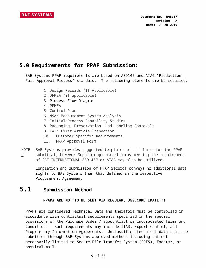
5.0 Requirements for PPAP Submission:BAE Systems PPAP requirements are based on AS9145 and AIAG "Production Part Approval Process" standard. The following elements are be required:
1. Design Records (If Applicable)2. DFMEA (if applicable)3. Process Flow Diagram4. PFMEA5. Control Plan6. MSA: Measurement System Analysis7. Initial Process Capability Studies8. Packaging, Preservation, and Labeling Approvals9. FAI: First Article Inspection10.Customer Specific Requirements11.PPAP Approval Form
NOTE:
BAE Systems provides suggested templates of all forms for the PPAP submittal, however Supplier generated forms meeting the requirements of SAE INTERNATIONAL AS9145™ or AIAG may also be utilized. Completion and submission of PPAP records conveys no additional data rights to BAE Systems than that defined in the respective Procurement Agreement
5.1 Submission Method PPAPs ARE NOT TO BE SENT VIA REGULAR, UNSECURE EMAIL!!!
PPAPs are considered Technical Data and therefore must be controlled in accordance with contractual requirements specified in the special provisions of the Purchase Order / Subcontract or incorporated Terms and Conditions. Such requirements may include ITAR, Export Control, and Proprietary Information Agreements. Unclassified technical data shall be submitted through BAE Systems approved methods including but not necessarily limited to Secure File Transfer System (SFTS), Exostar, or physical mail. Classified technical data shall be specially handled as specified in the Purchase Order or Subcontract. Contact your BAE Systems procurement representative to confirm the approved transmittal method.
8 of 29
Document No. B45157Revision: A
Date: 7 Feb 2019
5.2 Submission Status The PPAP approval process will be carried out by BAE Systems. The PPAP submission will be reviewed and dispositioned one of the following ways:
APPROVED:
A formal acceptance of the submission which has met all of the criteria set by BAE Systems
REJECTED: The submission is not acceptable and does not meet the criteria set by BAE Systems
INTERIM: An interim approval can be given if it is deemed by BAE Systems that product is useable. The interim status is a temporary approval for a specified time-frame which is determined by BAE Systems. The supplier must implement the required corrective actions and re-submit PPAP for full approval during this time frame. If a re-submission does not occur within the required time-frame the PPAP will be rejected.
5.3 Ongoing Requirements BAE Systems reserves the right to request any information you have provided in any data or document in any element of approval, at any time, including after the approval has been granted. The PF, CP, and PFMEA are “living” documents and should be updated as risks are mitigated, new risks are identified, or additional controls are put in place.
6.0 Instructions for completing a PPAP SubmissionThe Part Submission Warrant (PSW) must be filled out and signed by the supplier.
The part number must match the Purchase Order issued by BAE Systems.
The correct Hardware and Drawing revision level and submission level must be entered.
Any fields that do not apply to your submission should be filled in with “N/A” (Not Applicable).
It is important that the PPAP approval Form is filled out correctly and contains accurate and legible information.
9 of 29
Figure 1: BAE Systems PPAP Submission Form

Document No. B45157Revision: A
Date: 7 Feb 2019
6.1 Design Records and Ballooned Drawings The purpose of designed records and ballooned drawings is to document and provide a copy of the formal print and to provide any additional engineering records for reference.
Figure 2: Ballooned Drawing Example
A ballooned drawing shows the parts or assemblies in a part print with numbered “balloons” that point to individual requirements of the part. The numbers on the ballooned drawing correlate with the numbers found on the Dimensional Data Sheet. A ballooned drawing must be submitted as part of the PPAP for every submission when dimensional results are required.
6.1.1 Completing the balloon drawing
All part requirements on the BAE Systems or Supplier print must be ballooned and numbered for reference and measurement. These may include:1. Dimensions and tolerance of parts2. Electrical requirements (performance data, functional tests, etc)3. Visual features (color, texture, etc)4. Chemical characteristics (cure time, etc)5. Physical and mechanical properties (tensile strength, plating thickness, heat treat
hardness, etc)6. Any other specified requirement that you have the capability to measure or that is
described in the print notes or reference specifications.When dimensions are specified at multiple location on the drawing, the data for each location should be numbered separately.
10 of 29

Document No. B45157Revision: A
Date: 7 Feb 2019
6.2 Approved Engineering Change Documentation When a supplier identifies a drawing or specification issue/error and recommends a change to the BAE Systems drawing. A Supplier Variation Request (SVR) may be submitted to BAE Systems to review and approve the requested the change. The SVR should be made prior to fabrication or as early in the fabrication process as possible.Please note the following:
1. Material not in compliance with drawing(s) or specification(s) shall NOT be shipped without prior BAE Systems Approval.
2. The supplier must receive an approved and closed SVR as authorization to ship product.
1. If the SVR disposition requires a drawing change then upon release of the ECO, a PO revision change will be issued to reflect the new part revision Product should not ship until ECO is completed and the SVR closed.
3. The supplier shall not perform any repair activity before getting BAE Systems approval via a documented repair procedure approved on the SVR by BAE Systems.
A copy of the Supplier Variation Request form and submission instructions can be found on the BAE Systems Supplier Quality Assurance Portal.
6.3 Customer Engineering Approvals The supplier submission is to include BAE Systems Engineering Approval documentation when requested. This will only be requested if the supplier has design authority of the parts/products.
11 of 29

Document No. B45157Revision: A
Date: 7 Feb 2019
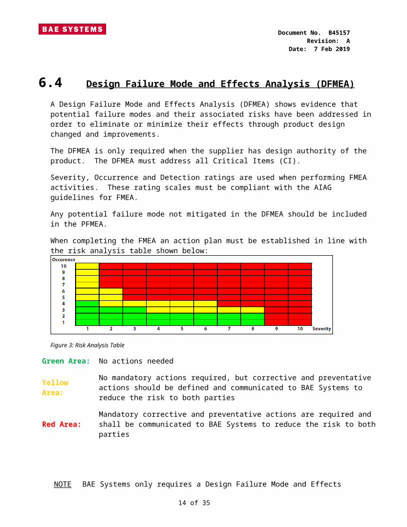
6.4 Design Failure Mode and Effects Analysis (DFMEA) A Design Failure Mode and Effects Analysis (DFMEA) shows evidence that potential failure modes and their associated risks have been addressed in order to eliminate or minimize their effects through product design changed and improvements.The DFMEA is only required when the supplier has design authority of the product. The DFMEA must address all Critical Items (CI).Severity, Occurrence and Detection ratings are used when performing FMEA activities. These rating scales must be compliant with the AIAG guidelines for FMEA. Any potential failure mode not mitigated in the DFMEA should be included in the PFMEA.When completing the FMEA an action plan must be established in line with the risk analysis table shown below:
Figure 3: Risk Analysis Table
Green Area: No actions needed
Yellow Area:
No mandatory actions required, but corrective and preventative actions should be defined and communicated to BAE Systems to reduce the risk to both parties
Red Area: Mandatory corrective and preventative actions are required and shall be communicated to BAE Systems to reduce the risk to both parties
NOTE:
BAE Systems only requires a Design Failure Mode and Effects Analysis (DFMEA) to be included if the supplier has design authority.
12 of 29

Document No. B45157Revision: A
Date: 7 Feb 2019
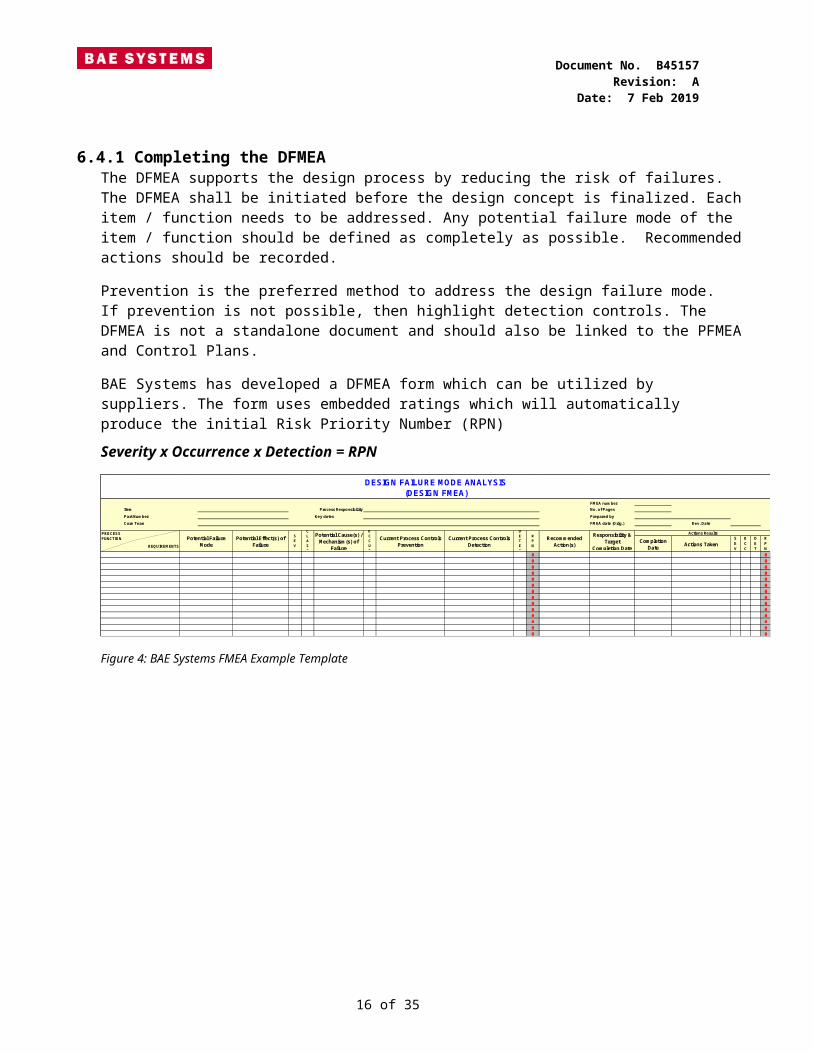
6.4.1 Completing the DFMEAThe DFMEA supports the design process by reducing the risk of failures. The DFMEA shall be initiated before the design concept is finalized. Each item / function needs to be addressed. Any potential failure mode of the item / function should be defined as completely as possible. Recommended actions should be recorded. Prevention is the preferred method to address the design failure mode. If prevention is not possible, then highlight detection controls. The DFMEA is not a standalone document and should also be linked to the PFMEA and Control Plans.BAE Systems has developed a DFMEA form which can be utilized by suppliers. The form uses embedded ratings which will automatically produce the initial Risk Priority Number (RPN) Severity x Occurrence x Detection = RPN
FMEA numberItem Process Responsibility No. of Pages
Part Number Key dates Prepared byCore Team FMEA date (Orig.) Rev. Date
0 00 00 00 00 00 00 00 00 00 00 00 00 00 0
DESIGN FAILURE MODE ANALYSIS(DESIGN FMEA)
Potential Cause(s) / Mechanism(s) of
Failure
OCCUR
Current Process Controls Prevention
Current Process Controls Detection
DETEC
RPN
PROCESSFUNCTION Potential Failure
ModePotential Effect(s) of
Failure
SEV
CLASS
Recommended Action(s)
Responsibility & Target
Completion Date
Actions Results
Completion Date Actions Taken
SEV
OCC
DET
RPNREQUIREMENTS
Figure 4: BAE Systems FMEA Example Template
13 of 29
Document No. B45157Revision: A
Date: 7 Feb 2019
6.4.2 Severity (DFMEA)An assessment of how serious the Failure Effect (due to the Failure Mode) is to the
customer:
Category(Product)
Criteria: Severity of Effect(Effect on Product) - DFMEA & PFMEA
Ranking
Safetyand/or
RegulatoryCompliance
Potential failure more affects safe vehicle operation and/or involve noncompliance with government regulation without warning
10
Potential failure more affects safe vehicle operation and/or involve noncompliance with government regulation with warning
9
Primary Function
Essential
Loss or primary function (vehicle inoperable, does not affect safe vehicle operation) 8
Degradation or primary function (vehicle operable, but at reduced level or performance) 7
Secondary Function
Convenient
Loss of secondary function (vehicle operable, but comfort / continence functions inoperable) 6
Degradation or secondary function (vehicle operable, but comfort / continence functions at reduced level of performance)
5
Annoyance
Appearance or Audible Noise, vehicle operable, item does not conform. Defect noticed by most customers (>75%)
4
Appearance or Audible Noise, vehicle operable, item does not conform. Defect noticed by many customers (50%)
3
Appearance or Audible Noise, vehicle operable, item does not conform. Defect noticed by discriminating customers (<25%)
2
No Effect No discernible effect 1
Table 1: SAE J1739 Appendix A - DFMEA
14 of 29

Document No. B45157Revision: A
Date: 7 Feb 2019
6.4.3 Occurrence (DFMEA)An assessment of the likelihood that a particular cause will happen and result in the Failure Mode:
Likelihood of Failure
Criteria: Occurrence and Cause - DFMEA(Design Life/reliability or item/vehicle) Rank
Very High New Technology/ new design with no history 10
High
Failure is inevitable with new design, new application, or change in duty cycle/operating conditions.
9
Failure is likely with new design, new application, or change in duty cycle/operating conditions.
8
Failure is uncertain with new design, new application, or change in duty cycle/operating conditions.
7
Moderate
Frequent failures associated with similar designs or in design simulation and testing. 6
Occasional failures associated with similar designs or in design simulation and testing. 5
Isolated failures associated with similar designs or in design simulation and testing. 4
Low
Only isolated failures associated with almost identical design or in design simulation and testing
3
No observed failures associated with almost identical design or in design simulation and testing
2
Very Low Failure is eliminated through preventative control 1
Table 2: SAE J1739 Appendix B - DFMEA
15 of 29
Document No. B45157Revision: A
Date: 7 Feb 2019
6.4.4 Detection (DFMEA)An assessment of the likelihood that the current controls will detect the cause of the Failure Mode or the Failure Mode itself, should it occur, thus PREVENTING the Failure Effect from reaching your customer. The customer in this case could be the next operation, subsequent operations, or the end user:Category(Product)
DFMEA Criteria:Likelihood of Detection by Design Control Rank
Absolute Uncertainty
No current design control; Cannot detect or is not analyzed10
Difficult to Detect
Design analysis/detection controls have weak detection capability; Virtual Analysis (e.g. CAE, FAE, etc.) is not correlated to expected actual operating conditions.
9
Post Design Freeze and Prior to Launch
Product verification /validation after design freeze and prior to launch with pass/fail testing (sub-system or system testing with acceptance criteria e.g. Ride & handling, shipping evaluation, etc.)
8
Product verification/validation after design freeze and prior to launch with test to failure testing (Sub-system or system testing until failure occurs, testing of system interactions, etc.)
7
Product verification/validation after design freeze and prior to launch with degradation testing (Sub-system or system testing after durability test e.g. Function check)
6
Prior to Design Freeze
Product Validation (reliability testing, development or validation tests) prior to design freeze using pass/fail testing (e.g. acceptance criteria for performance, function checks, etc.)
5
Product Validation (reliability testing, development or validation tests) prior to design freeze using test to failure testing (e.g. Until leaks, yields, cracks, etc.)
4
Product Validation (reliability testing, development or validation tests) prior to design freeze using degradation testing (e.g. data trends, before/after values etc.)
3
Virtual Analysis - Correlated
Design analysis/detection controls have strong detection capability. Virtual Analysis (e.g. CAE, FAE, etc.) is highly correlated with actual and/or expected actual operating conditions prior to design freeze
2
Detection not applicable; Error Prevention
Failure cause or Failure mode cannot occur because it is fully prevented through design solutions (e.g. Proven design standard/best practice or common material, etc.) 1
Table 3: SAE J1739 Appendix C - DFMEA16 of 29

Document No. B45157Revision: A
Date: 7 Feb 2019
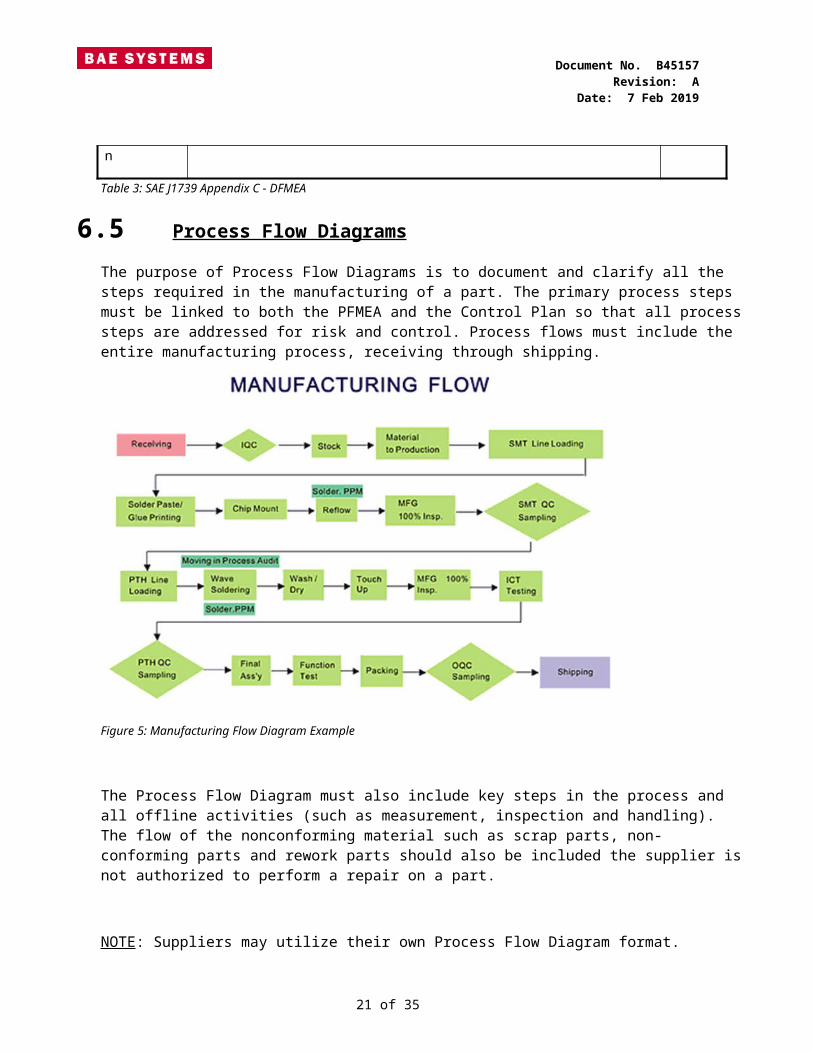
6.5 Process Flow Diagrams The purpose of Process Flow Diagrams is to document and clarify all the steps required in the manufacturing of a part. The primary process steps must be linked to both the PFMEA and the Control Plan so that all process steps are addressed for risk and control. Process flows must include the entire manufacturing process, receiving through shipping.
Figure 5: Manufacturing Flow Diagram Example
The Process Flow Diagram must also include key steps in the process and all offline activities (such as measurement, inspection and handling). The flow of the nonconforming material such as scrap parts, non-conforming parts and rework parts should also be included the supplier is not authorized to perform a repair on a part.
NOTE: Suppliers may utilize their own Process Flow Diagram format.
17 of 29

Document No. B45157Revision: A
Date: 7 Feb 2019
6.6 Process Failure Mode Effects Analysis (PFMEA) The Process Failure Mode Effects Analysis (PFMEA) is used to show evidence that any potential mA PFMEA should be performed for every part, piece or equipment or process involved in manufacturing. The PFMEA is a cross functional activity and should not be conducted in isolation.When calculating the Risk Priority Number (RPN) for the PFMEA the following rating mechanism should be utilized to assess Severity, Occurrence, and Detection: (Severity x Occurrence x Detection = RPN)
FMEA numberItem Process Responsibility No. of PagesPart Number Key dates Prepared by
Core Team FMEA date (Orig.) Rev. Date
0 00 00 00 00 00 00 0
Current Process Controls Prevention
Current Process Controls Detection
DETEC
RPN
Actions Results
Completion Date
Recommended Action(s)
Responsibility & Target Completion
Date
POTENTIAL FAILURE MODE ANALYSIS(PROCESS FMEA)
SEV
CLASS
Potential Cause(s) / Mechanism(s) of
Failure
OCCUR
PROCESSFUNCTION Potential Failure
ModePotential Effect(s) of
FailureREQUIREMENTS
Figure 6: BAE Systems PFMEA Template
The PFMEA worksheet is a tool used to identify and show potential process risks associated with the manufacture of each part. It also highlights the controls at each stage of the manufacturing process; this detail should read across to the Control Plan.
18 of 29

Document No. B45157Revision: A
Date: 7 Feb 2019
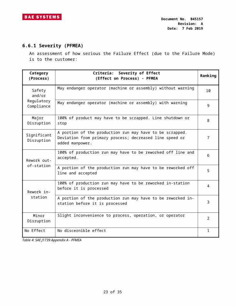
6.6.1 Severity (PFMEA)An assessment of how serious the Failure Effect (due to the Failure Mode) is to the customer:
Category(Process)
Criteria: Severity of Effect(Effect on Process) - PFMEA
Ranking
Safetyand/or
RegulatoryCompliance
May endanger operator (machine or assembly) without warning 10
May endanger operator (machine or assembly) with warning9
Major Disruption
100% of product may have to be scrapped. Line shutdown or stop 8
SignificantDisruption
A portion of the production run may have to be scrapped. Deviation from primary process; decreased line speed or added manpower. 7
Rework out-of-station
100% of production run may have to be reworked off line and accepted. 6
A portion of the production run may have to be reworked off line and accepted 5
Rework in-station
100% of production run may have to be reworked in-station before it is processed 4
A portion of the production run may have to be reworked in-station before it is processed 3
Minor Disruption
Slight inconvenience to process, operation, or operator2
No Effect No discernible effect 1
Table 4: SAE J1739 Appendix A - PFMEA
19 of 29

Document No. B45157Revision: A
Date: 7 Feb 2019
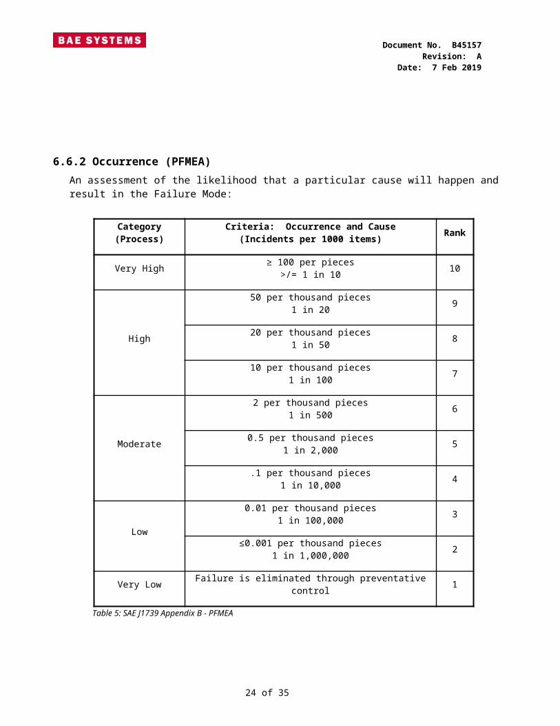
6.6.2 Occurrence (PFMEA)An assessment of the likelihood that a particular cause will happen and result in the Failure Mode:
Category(Process)
Criteria: Occurrence and Cause(Incidents per 1000 items) Rank
Very High ≥ 100 per pieces>/= 1 in 10 10
High
50 per thousand pieces1 in 20 9
20 per thousand pieces1 in 50 8
10 per thousand pieces1 in 100 7
Moderate
2 per thousand pieces1 in 500 6
0.5 per thousand pieces1 in 2,000 5
.1 per thousand pieces1 in 10,000 4
Low
0.01 per thousand pieces1 in 100,000 3
≤0.001 per thousand pieces1 in 1,000,000 2
Very Low Failure is eliminated through preventative control 1
Table 5: SAE J1739 Appendix B - PFMEA
20 of 29
Document No. B45157Revision: A
Date: 7 Feb 2019
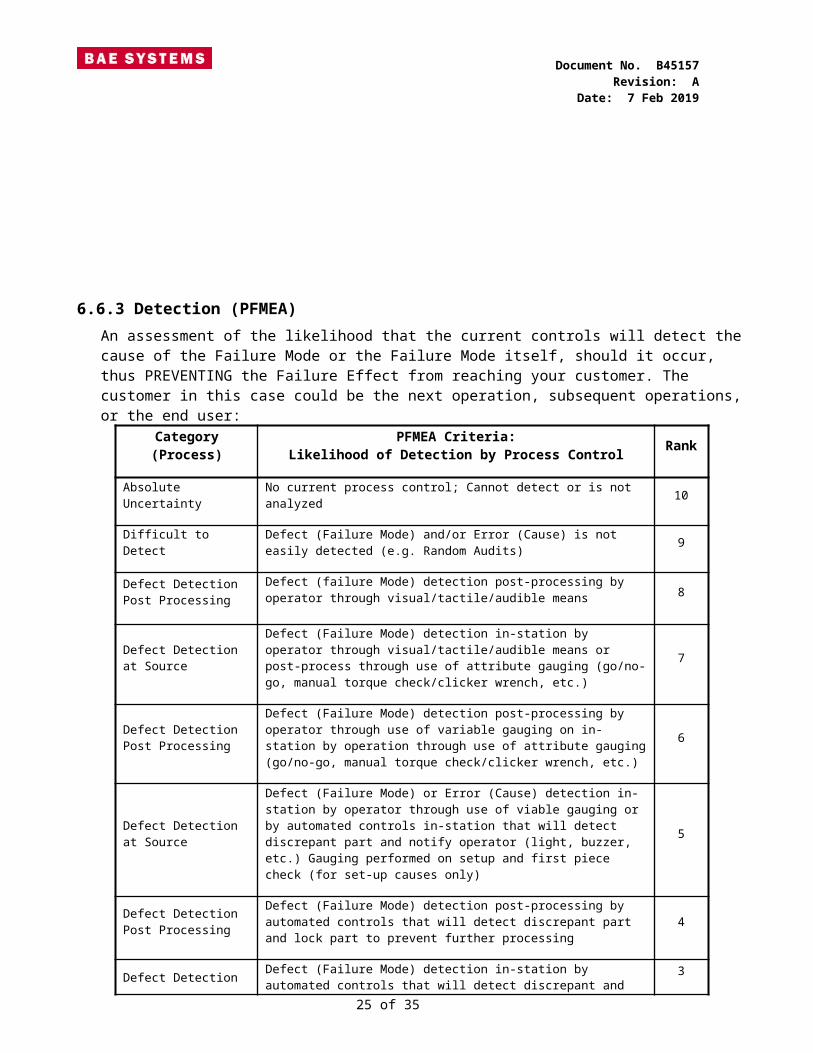
6.6.3 Detection (PFMEA)An assessment of the likelihood that the current controls will detect the cause of the Failure Mode or the Failure Mode itself, should it occur, thus PREVENTING the Failure Effect from reaching your customer. The customer in this case could be the next operation, subsequent operations, or the end user:
Category(Process)
PFMEA Criteria:Likelihood of Detection by Process Control Rank
Absolute Uncertainty
No current process control; Cannot detect or is not analyzed 10
Difficult to Detect Defect (Failure Mode) and/or Error (Cause) is not easily detected (e.g. Random Audits) 9
Defect Detection Post Processing
Defect (failure Mode) detection post-processing by operator through visual/tactile/audible means 8
Defect Detection at Source
Defect (Failure Mode) detection in-station by operator through visual/tactile/audible means or post-process through use of attribute gauging (go/no-go, manual torque check/clicker wrench, etc.)
7
Defect Detection Post Processing
Defect (Failure Mode) detection post-processing by operator through use of variable gauging on in-station by operation through use of attribute gauging (go/no-go, manual torque check/clicker wrench, etc.)
6
Defect Detection at Source
Defect (Failure Mode) or Error (Cause) detection in-station by operator through use of viable gauging or by automated controls in-station that will detect discrepant part and notify operator (light, buzzer, etc.) Gauging performed on setup and first piece check (for set-up causes only)
5
Defect Detection Post Processing
Defect (Failure Mode) detection post-processing by automated controls that will detect discrepant part and lock part to prevent further processing
4
Defect Detection at Source
Defect (Failure Mode) detection in-station by automated controls that will detect discrepant and automatically lock part in station to prevent further processing
3
Error Detection and/or Defect Prevention
Error (Cause) detection in-station by automated controls that will detect error and prevent discrepant part from being made. 2
Detection not applicable; Error Prevention
Error (Cause) prevention as a result of figure design, machine design or part design. 1
Table 6: SAE J1739 Appendix C – PFMEA
21 of 29

Document No. B45157Revision: A
Date: 7 Feb 2019
6.7 Control Plan A Control Plan defines the operation, processes, materials, equipment, methodologies and CIs for controlling variations in key product or process characteristics integral to the manufacturing process. Its purpose is to communicate the supplier’s decisions during the entire manufacturing process from material purchase through to final shipping. Specifically the control plan should address the following:
1. Methods of production2. Identification of KC characteristics3. Secondary or Outsourced Operations4. Materials and their physical and chemical characteristics5. Types of process equipment at each operation6. Types of test equipment used to measure each characteristic7. Specifications, sampling strategy, control and reaction methods used.8. Periodic conformance testing and product verification
All processes must have a control plan that defines all methods used for process control and complies with BAE Systems specified requirements. The control plan must clearly state each step in the process; the specification and all KC characteristics must be addressed for product and process. The Process Flow Diagram, PFMEA and Control Plan must be linked. Each major process step in the process flow diagram should correlate with PFMEA steps and there should be documented control plan actions for each of the steps.
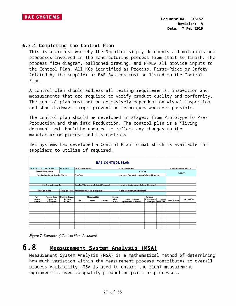
6.7.1 Completing the Control PlanThis is a process whereby the Supplier simply documents all materials and processes involved in the manufacturing process from start to finish. The process flow diagram, ballooned drawing, and PFMEA all provide inputs to the Control Plan. All KCs identified as Process, First-Piece or Safety Related by the supplier or BAE Systems must be listed on the Control Plan. A control plan should address all testing requirements, inspection and measurements that are required to verify product quality and conformity. The control plan must not be excessively dependent on visual inspection and should always target prevention techniques wherever possible.The control plan should be developed in stages, from Prototype to Pre-Production and then into Production. The control plan is a “living” document and should be updated to reflect any changes to the manufacturing process and its controls.BAE Systems has developed a Control Plan format which is available for suppliers to utilize if required.
22 of 29
Document No. B45157Revision: A
Date: 7 Feb 2019
Proto-Type Pre-Launch Production Key Contact / Phone Date of OriginationControl Plan Number
Part Number / Latest Revision Change Core Team Customer Engineering Approval / Date (If Required)
Part Name / Description Supplier / Plant Approval / Date (If Required) Customer Quality Approval / Date (If Required)
Supplier / Plant Supplier Code Other Approval / Date (If Required) Other Approval / Date (If Required)
Part / Process Name / Machine, Device, Characteristics SpecialProcess Operation Jig, Tools Char. Product / Process MeasurementNumber Description for Mfg. Class Specification / Tolerance Technique Size Freq.
BAE CONTROL PLAN
Date of Latest Revision - ref.
M/DD/YYM/DD/YY
Reaction PlanSample Control MethodNo. Product Process
Methods
Figure 7: Example of Control Plan document
6.8 Measurement System Analysis (MSA) Measurement System Analysis (MSA) is a mathematical method of determining how much variation within the measurement process contributes to overall process variability. MSA is used to ensure the right measurement equipment is used to qualify production parts or processes.BAE Systems requires an MSA study to be conducted on all measurement equipment that is used to accept or fail the product. This generally covers all measurement tools identified in the control plan.A Gauge Repeatability and Reproducibility (GR&R) study is used to ensure that measurements taken in the manufacturing process and reasonably consistent regardless of how many times they are performed or how had performed them. It is important to select a sample size that encompasses the full range of parts.BAE Systems recommends the following acceptance levels to be used:
1. % R&R should be 10% or less for CIs2. Marginal gauges (between 10% and 30%) should have an action plan to address
and improve the method of measurement.3. Gauges with R&R at 30% or more must not be used.
Statistical software, IE: Mini-tab, SPC Excel or equivalent may be utilized to conduct the measurement study. BAE Systems has also developed at GR&R worksheet for the
23 of 29
Document No. B45157Revision: A
Date: 7 Feb 2019
suppliers to utilize. Instructions on how to complete the GR&R are included in the worksheet.
Hold Cursor Here for DirectionsPart Number: Comments:
Part Revision:Part Description: Nominal=
Date Completed: + TOL=Gage Name: -TOL =
Gage Number:Cal Date:
Measurements
OPER1 OPER2 OPER3 OPER4 OPER5
Part trial 1 trial 2 Range trial 1 trial 2 Range trial 1 trial 2 Range trial 1 trial 2 Range trial 1 trial 2 Range123456789
10X-bar X-bar X-bar X-bar X-bar
# persons R-bar R-bar R-bar R-bar R-bar# parts (n) MaxR MaxR MaxR MaxR MaxR
# trial (m)LSL 0.000 USL 0.000 Max X-bar 0.0000 R-double bar =
a 0.00 Total Tolerance 0.0000 Min X-bar 0.0000 UCLR = R-double bar x D4
b 0.00 X-bar diff 0.0000 UCLR =D4 = 0.00 If R values in study are greater
than UCLR, these are statisticaloutlier and need evaluation
Repeatability Reproductibility GAGE R&REV=(R-double bar) x a Av=(X-bar dif f x b)2-(EV)2/n/m)1/2 R&R = (EV2+AV2)1/2
EV= AV = R&R =
%EV = 100(EV/tolerance) %AV = 100(AV/tolerance) %R&R = 100(R&R/tolerance)
%EV = %AV = %R&R = 0.0%
GAUGE R&R TEMPLATE
Figure 8: Example of GR&R worksheet
6.9 Packaging A packaging, preservation, and labeling plan shall at a minimum define:
1. Packaging process & pictures2. Internal packaging material (including identification if it is ESD safe)3. Packaging reusability (as applicable) 4. Labeling requirement, including label content (part number, SN, barcodes, etc),
label material, and label location(s)5. Qty per box and (as applicable) boxes per pallet 6. Box size & weight
24 of 29
Document No. B45157Revision: A
Date: 7 Feb 2019
6.10Dimensional Results The Dimensional Results are documented in the Dimensional Data Sheet referenced earlier in this document. The measurements in this form should correlate with your ballooned drawing from Item 6.1.The parts used for dimensional data must be from production tooling / process and randomly sampled (if possible) from a run at production rate. The dimensional report must address all of the following:
1. All dimensions2. All applicable notes on the drawing3. Any dimensions contained on reference prints
NOTE: The parts measured to obtain the dimensional results must be the same parts submitted for PPAP approval
6.10.1 Completing the Dimensional Data Sheet
All dimensional requirements on the ballooned drawing must be listed on the dimensional data sheet. All sections of the dimensional data sheet must be filled out completely. The measurement method must be documented for every line item. When a specific feature on the drawing has multiple requirements I.E. GD&T symbols the data must be recorded on individual line items with the dimensional data sheet.Example: This call out would require 3 lines of separate data on the dimensional report.
1. Hole diameter (25+/-0.2)2. True Position (0.05 MMC on datum A,B,C)3. Cylindricity (0.1)
Figure 9: Dimensional Drawing Example
Dimensional Data and all requirements should be documented via the standard BAE Systems FAI process per BAE Systems Supplier Requirements for First Article Inspections Reports, B25279:
25 of 29

Document No. B45157Revision: A
Date: 7 Feb 2019
Figure 10: AS9102 Form 2 Example
Figure 11: AS9102 Form 3 Example
NOTE: Any concerns identified in the Dimensional Data should be brought to the attention of BAE Systems before submitting your PPAP.
26 of 29
Document No. B45157Revision: A
Date: 7 Feb 2019
6.11Material and Performance Test Results The purpose of this item is to ensure that the material is verified for its properties and acceptable performance is demonstrated.Material test results should be provided in the form of a material composition report also called a Certificate of Analysis (CofA) from an accredited lab that confirms the material content meets a known standard, IE: Chemical and Physical Analysis Report.It is the Supplier’s responsibility to confirm the composition of material not only at PPAP submission stage but also ongoing during the life of the product / project. This step should be placed into the FMEA process and the Control Plan.A Certificate of Compliance (C of C) is acceptable during production shipping but is not acceptable during PPAP submission as the C of C will not give actual test results.Performance Test Results should be acceptable, and meet the agreed upon specifications to be measured. Performance results may include data confirming any referenced specifications in the part print or specific testing required by BAE Systems. BAE Systems will communicate specific material, performance and testing requirements either in the part print, reference specifications or by a specific request prior to PPAP approval. It is the responsibility of the supplier to confirm the data and format of this requirement with the appropriate BAE Systems representative.Test Data should not be submitted with the PPAP unless the purchase order calls contains a material clause such as 111, 134, 135 or 168. The prior list is not meant to be all inclusive as all clauses should be reviewed and requirements identified as part of your contract review.
6.12Initial Process Study (Cpk, Ppk) The purpose of initial process studies (Cp, Cpk, Pp, Ppk) is to determine if the production process is likely to manufacture product that will meet BAE Systems requirements. Initial process studies (capability) are highly recommended for all CIs.There are two primary indexes used in determining process capability.Cpk predicts future capability and should be used when developing new parts or revising specifications on a part. Cpk should also be used when materials, processes, manufacturing location, or equipment have changed or Material suppliers have changed.Ppk indicates past performance. Use Ppk when you are a new supplier to BAE Systems but have already been manufacturing the part which BAE Systems will purchase.The capability study is to be performed on samples taken from an actual production run at the quoted production rates. The minimum acceptance capability for all CIs is 1.33 and 1.67 for all safety related CI’s. In some cases, it may be impossible or prohibitively expensive to meet the stability and capability requirements. These exceptions shall be documented by the producer and require customer approval. An alternative control method (such as 100% gauging) may be required.
27 of 29

Document No. B45157Revision: A
Date: 7 Feb 2019
The supplier can submit the Capability data on the format of their choice, and Mini-tab, SPC Excel or equivalent may be utilized.
6.13Qualified Laboratory Documentation The purpose of Qualified Laboratory Documentation is to ensure that the testing for PPAP has been done by a qualified lab. If your organization is performing testing or measurement internally or externally at an outside facility, then proof of Scope and accreditation is required.
6.13.1 Internal Labs located at Supplier
All suppliers that have testing or measurement performed on site must provide the following in this section of the PPAP submission:
A. Record / Scope that identifies the testing to be done and it must include:B. List of your personnel’s competency and training to perform the testing.C. List of all test equipment used in process and offline.D. List of methods and standards used to calibrate the equipment.
6.13.2 External Labs located offsite from the Supplier
If you are sending out for measurement and testing, you must ensure that you use an accredited lab and can provide proof of accreditation. BAE Systems prefers external labs be accredited to known standards such as ISO 17025, ISO 10012:2004, or ANSI/NCSL Z540-1-1994.
1. Provide a copy of the lab company’s Third Party accreditation.2. Results must be on company letterhead and include the following:
1. The name of the lab2. Date of testing3. Standards used for testing
6.14Sample Parts Sample parts are to be included and are to be the actual samples measured in the dimensional analysis (Item 6.10). Sample parts are to be delivered with or before the PPAP submission.The PPAP samples should be delivered with the label identifying them as PPAP Samples.
This is to avoid the PPAP sample parts being inadvertently misplaced or mixed up with production parts.
28 of 29

Document No. B45157Revision: A
Date: 7 Feb 2019
6.15Checking Aids The purpose of this item is to provide evidence that the checking aids used to verify product exist and have been properly validated.There are many different types of checking aids. Examples of checking aids include but are not limited to certified check fixtures, un-certified check fixtures, templates, custom gauges and test equipment.BAE Systems requires all checking aids to be verified as repeatable through an MSA study. The MSA can be either attribute or variable depending on the type of checking aid in use.
6.16Customer Specific Requirements This item is to address BAE Systems specific requirements during PPAP submission.BAE Systems will advise during the PPAP process on specific requirements as there may vary depending on the scope of the project / product being supplied. This item is also utilized to flow down requirements of BAE Systems customers to ensure these elements are captured during PPAP submission.
29 of 29