pvp specs
TRANSCRIPT
8/3/2019 PVP Specs
http://slidepdf.com/reader/full/pvp-specs 1/12
LEED Certification
The Project has an aspiration to be assessed against the requirements of LEED for New Construction 2009edition, and during the design phase is targeting a LEED Gold Certification.
1. SCOPE OF WORK
The contractor will be responsible for providing a complete and operable Photovoltaic (PV) System(System) that meets the contract requirements and the latest available regulations. The contractor willbe required to design the photovoltaic system [MAX OUTPUT], select the most appropriate photovoltaicequipment, install the photovoltaic system and undertake all requisite activities on behalf of the owner toprovide a turnkey photovoltaic system. The contractor shall provide qualified and experienced staff for all aspects of the Project, and such staff shall be specifically qualified and experienced in theengineering, design, installation, and operation of photovoltaic systems.
1.2.1. GENERAL
Contractor must include a description of the Proposed System. The System description shall include thePV panel/module size (in kW and physical dimensions) and layout, the mounting details of the arrays,the electrical interconnection strategy, construction means and methods, and energy productioncalculations. The contractor is responsible to verify the site conditions.
a) PV Panel/Module Size and Layout – Contractor shall include a description and show a layout of all the PV panels/modules and all other System components, including utility requireddisconnect switches proposed for the Project. Include the kW produced for the ProposedSystem as well as the physical dimensions of the panels/modules and the physical dimensionsof the space needed to mount the panels/modules.
b) PV Array Mounting Details – Contractor shall include a detailed description of, and drawings of,the structural attachment details for the System. The solar array shall be a roof mountedsystem.
c) Electrical Interconnection – Contractor shall include a description of the strategy for theproposed System. This shall include single-line electrical drawings showing the System output(voltage, phase and current) and the method of connecting the System. The contractor will beresponsible for connecting the System to certain loads at the Project site using changeover
switches of the required rating. The solar arrays shall maintain the integrity and reliability of theProject Site electrical system. The Contractor shall carefully inspect the electrical system anddesign to ensure against harmonic distortion, fault protection issues, and interconnect problems.The arrays shall integrate with the emergency power system that supports the facility.
d) Production of Electricity – Contractors must provide evidence of total kW (ac) installed andanticipated annual kWh (ac) production for the proposed System. Contractor shall furnish “PVWatts” electrical production results.
1.2.2 Selection of Photovoltaic System
The Contractor shall utilize the latest proven photovoltaic technology in design, construction andoperation of the System to maximize System reliability and output. Contractor must Package 2
8/3/2019 PVP Specs
http://slidepdf.com/reader/full/pvp-specs 2/12
provide catalog cut sheets and drawings with the submittal to show the type, style, and quantity of photovoltaic panels to be installed, the method of mounting panels on the site, and location of panelsand the grids the panels are attached to. The Contractor shall submit all drawings and specifications for the Project to the Engineer within the period stipulated in the project schedules. The drawings andspecifications shall show sufficient details as necessary to review the documents for structural integrity,operational integrity, and interaction with the existing building systems including but not limited toelectrical systems and any special foundation requirements for any components used in the Contractorsproposed System for this Project, which shall be shown on the drawings.
A. Contractor shall provide a detailed engineering package for the array including drawings,supporting calculations and related documentation. Contractor shall submit the drawingpackage to the Engineer for approval.
B. Contractor shall furnish revised “as-built” drawings after completion of the project.
C. Contractor shall furnish operation and maintenance (O&M) manuals for the system. Manualsshall be submitted at least one month prior to the project completion for review and approval bythe Engineer.
D. Contractor shall furnish and execute a detailed commissioning/quality assurance plan for theproject.
1.2.3 Engineering Design Package
A. Contractor shall develop a comprehensive design package consisting of drawings generated inAutoCAD version 2006 or later. Drawing package shall consist of the following drawings at aminimum:
1Cover sheet
2Site plan
3Symbols, abbreviations and notes
4Structural details and elevations
5Array layout with shading diagrams
6Single-line AC electrical diagrams
7Series and parallel string wiring diagrams
8Inverter installation details9Grounding diagrams and details
B. Contractor shall furnish packages for review.
C. Supporting Calculations
1. Structural and wind load calculations for each array. The Contractor will be required to perform a structuralassessment of the roof and PV support systems to ensure adequate support for the loading imposed by theSystem by a structural engineer.
2. Shading analysis.3. DC, AC wiring and sizing calculations. Package 24. The Contractor will be required to perform an assessment of the System and proposed interconnection alongwith the existing electrical distribution system to ensure the System may be interconnected in a safe and code
compliant manner. This assessment must be performed by a qualified electrical engineer.
5. Grounding wire sizing calculations.
8/3/2019 PVP Specs
http://slidepdf.com/reader/full/pvp-specs 3/12
1.2.4 Operation and Maintenance Manuals
A. Furnish O&M manuals including the following information:
1Manufacturer’s O&M data for each component
2System narrative description of operation
3Warranty information with contact information
4As-built drawings
5Safe system operation information
6Factory test reports
7Field test reports
8Spare parts list
9Factory test reports for each PV module indicating performance at Standard Test Conditions (STC).
1.2.5 Testing and Commissioning Plan
A. Contractor shall develop and submit a detailed written testing and commissioning plan that willconsist of the following:
1 System installation checks.
2System functional checks including all operational and safety checks.
3Comprehensive performance test to verify system capacity has been achieved.
B. Contractor shall maintain a written log of issues identified and corrected during the testing andcommissioning process.
1.3 Photovoltaic Array Design Criteria
1.3.1 General
A. Evaluate the peak kW generating capacity and the annual energy generation of the proposed system(per installed unit).
B. System must be rated at max output [TOTAL KW] of ac power. In addition, “PV Watts” calculationsneed to be provided.
C. The solar arrays shall maintain the integrity and reliability of the buildings electrical system. TheContractor shall carefully inspect the electrical system and design to ensure against harmonicdistortion, fault protection issues, and connect problems. The arrays shall integrate with theemergency power system that supports the plant.
8/3/2019 PVP Specs
http://slidepdf.com/reader/full/pvp-specs 4/12
Package 2D. The solar arrays shall be roof mounted.
E. System has to fit within the area identified on the roof for the system.
F. Contractor must provide detailed solar calculations.
G. Photovoltaic panels must provide at least a 25 year manufacturer’s warranty.
1.3.1 Array Layout
A. Array shall be located at the designated roof area to obtain a max output [TOTAL KW]. Contractor shall furnish “PV Watts” electrical production results.
B. Array layout shall account for obstructions, access to equipment, egress and safety perimeter clearances. Walking space shall be provided throughout the PV array to facilitate installation,inspection and maintenance access to all modules.
C. Array shall be designed to minimize shading of the solar modules. System shall be designed so thatshading will not occur between 9:00 am and 3:00 pm on winter solstice (shortest day of theyear). Contractor shall perform a detailed shading assessment, which will be required in their design package submittal.
D. The array shall be mounted in such a way that the normal drainage of the roof is not affected.
1.3.2 System Design Criteria
A. System shall conform to all applicable codes, standards including point and overall loads, wind andseismic load requirements. Wind uplift resistance shall meet expected 3-second gusts.
B. System shall maintain roof integrity and warrantee. The Contractor will provide a letter from theroofing contractor and/or roofing manufacturer indicating that the roof warranty is not affected bythe installation by the PV system, or will provide a replacement warranty of equivalent value.
C. System loading shall meet roof structural loads, both point and overall loads. The entire system shallnot weigh more than 5 pounds per square foot over the array area. Contractor shall furnishcalculations confirming this is met with their detailed design submittal. Contractor is responsible
for any structural modifications necessary to support the system.
D. Owner prefers that the mounting/support system shall be non-penetrating, self ballasted type. ShouldContractors design incorporate roof penetrations, he must meet conditions in section “B” above.
E. System shall elevate panels off of the roof for proper solar module cooling and allow for proper roof inspection and drainage. Mounting systems completely covering the roof surface (other thansupport feet) will not be accepted.
1.3.3 Mounting System Details
A. Contractor must include an extended warranty on the inverters to match the warranty of the system.Materials of construction shall be long-lasting with a service life of 30 years or greater. Systemshall be fabricated with corrosion resistant materials such as aluminum and stainless steel.
Stainless steel fasteners must be used.
8/3/2019 PVP Specs
http://slidepdf.com/reader/full/pvp-specs 5/12
Package 2
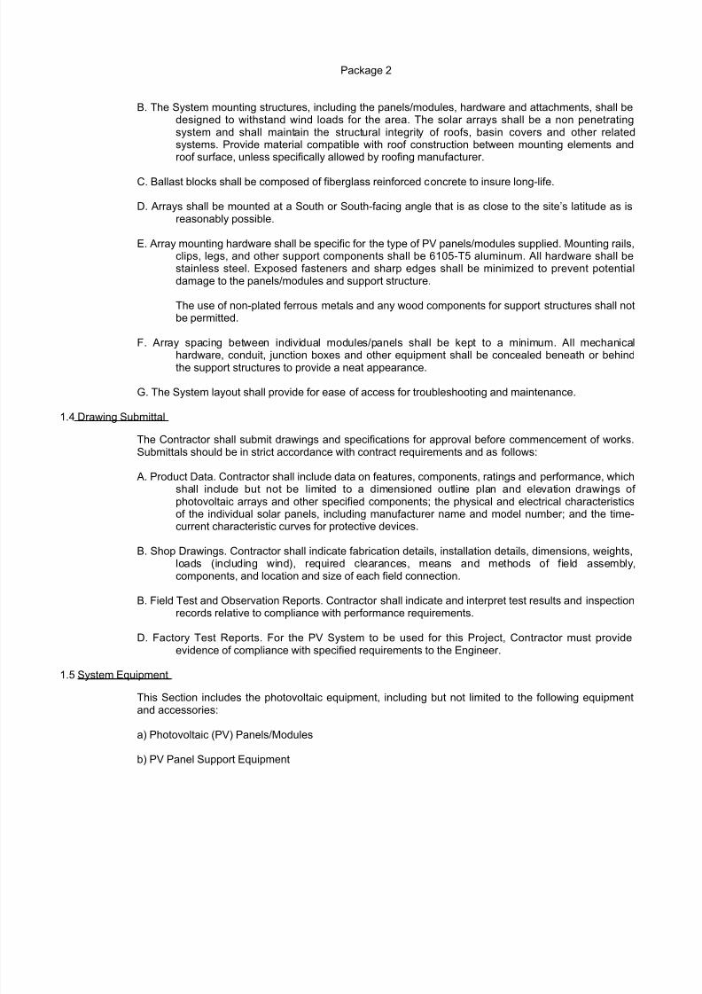
B. The System mounting structures, including the panels/modules, hardware and attachments, shall bedesigned to withstand wind loads for the area. The solar arrays shall be a non penetratingsystem and shall maintain the structural integrity of roofs, basin covers and other relatedsystems. Provide material compatible with roof construction between mounting elements androof surface, unless specifically allowed by roofing manufacturer.
C. Ballast blocks shall be composed of fiberglass reinforced concrete to insure long-life.
D. Arrays shall be mounted at a South or South-facing angle that is as close to the site’s latitude as isreasonably possible.
E. Array mounting hardware shall be specific for the type of PV panels/modules supplied. Mounting rails,clips, legs, and other support components shall be 6105-T5 aluminum. All hardware shall bestainless steel. Exposed fasteners and sharp edges shall be minimized to prevent potentialdamage to the panels/modules and support structure.
The use of non-plated ferrous metals and any wood components for support structures shall notbe permitted.
F. Array spacing between individual modules/panels shall be kept to a minimum. All mechanicalhardware, conduit, junction boxes and other equipment shall be concealed beneath or behindthe support structures to provide a neat appearance.
G. The System layout shall provide for ease of access for troubleshooting and maintenance.
1.4 Drawing Submittal
The Contractor shall submit drawings and specifications for approval before commencement of works.Submittals should be in strict accordance with contract requirements and as follows:
A. Product Data. Contractor shall include data on features, components, ratings and performance, whichshall include but not be limited to a dimensioned outline plan and elevation drawings of photovoltaic arrays and other specified components; the physical and electrical characteristicsof the individual solar panels, including manufacturer name and model number; and the time-
current characteristic curves for protective devices.
B. Shop Drawings. Contractor shall indicate fabrication details, installation details, dimensions, weights,loads (including wind), required clearances, means and methods of field assembly,components, and location and size of each field connection.
B. Field Test and Observation Reports. Contractor shall indicate and interpret test results and inspectionrecords relative to compliance with performance requirements.
D. Factory Test Reports. For the PV System to be used for this Project, Contractor must provideevidence of compliance with specified requirements to the Engineer.
1.5 System Equipment
This Section includes the photovoltaic equipment, including but not limited to the following equipmentand accessories:
a) Photovoltaic (PV) Panels/Modules
b) PV Panel Support Equipment
8/3/2019 PVP Specs
http://slidepdf.com/reader/full/pvp-specs 6/12
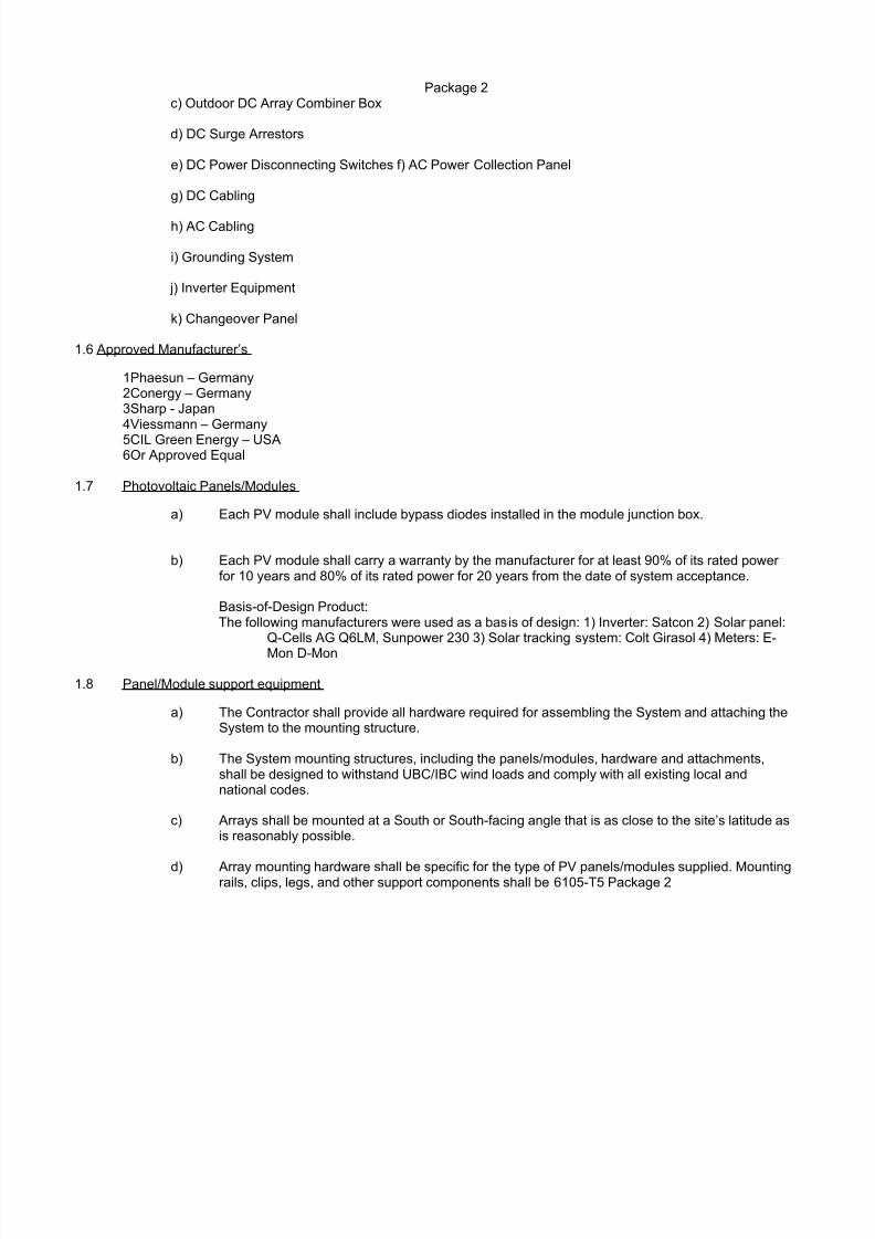
Package 2c) Outdoor DC Array Combiner Box
d) DC Surge Arrestors
e) DC Power Disconnecting Switches f) AC Power Collection Panel
g) DC Cabling
h) AC Cabling
i) Grounding System
j) Inverter Equipment
k) Changeover Panel
1.6 Approved Manufacturer’s
1Phaesun – Germany2Conergy – Germany3Sharp - Japan4Viessmann – Germany5CIL Green Energy – USA6Or Approved Equal
1.7 Photovoltaic Panels/Modules
a) Each PV module shall include bypass diodes installed in the module junction box.
b) Each PV module shall carry a warranty by the manufacturer for at least 90% of its rated power for 10 years and 80% of its rated power for 20 years from the date of system acceptance.
Basis-of-Design Product:The following manufacturers were used as a basis of design: 1) Inverter: Satcon 2) Solar panel:
Q-Cells AG Q6LM, Sunpower 230 3) Solar tracking system: Colt Girasol 4) Meters: E-
Mon D-Mon
1.8 Panel/Module support equipment
a) The Contractor shall provide all hardware required for assembling the System and attaching theSystem to the mounting structure.
b) The System mounting structures, including the panels/modules, hardware and attachments,shall be designed to withstand UBC/IBC wind loads and comply with all existing local andnational codes.
c) Arrays shall be mounted at a South or South-facing angle that is as close to the site’s latitude asis reasonably possible.
d) Array mounting hardware shall be specific for the type of PV panels/modules supplied. Mountingrails, clips, legs, and other support components shall be 6105-T5 Package 2
8/3/2019 PVP Specs
http://slidepdf.com/reader/full/pvp-specs 7/12
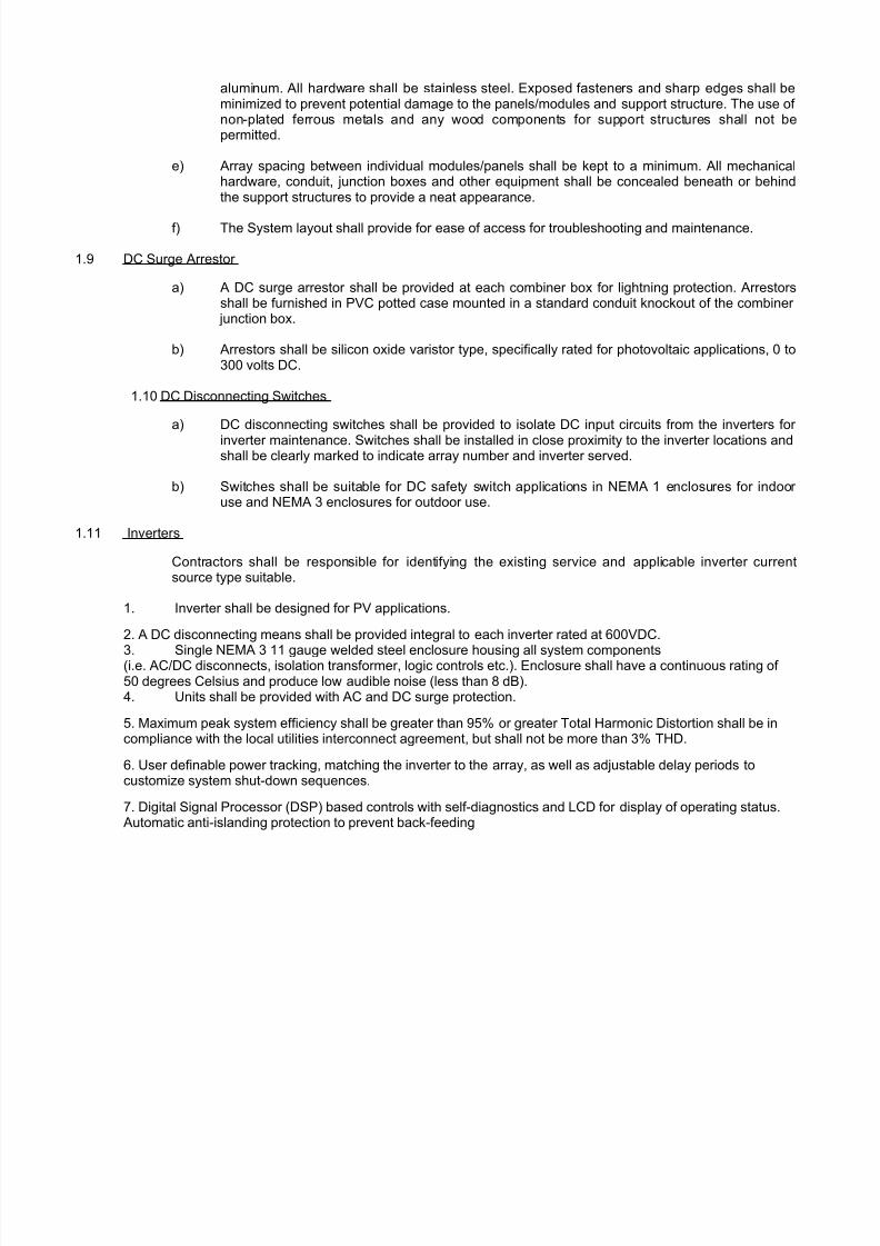
aluminum. All hardware shall be stainless steel. Exposed fasteners and sharp edges shall beminimized to prevent potential damage to the panels/modules and support structure. The use of non-plated ferrous metals and any wood components for support structures shall not bepermitted.
e) Array spacing between individual modules/panels shall be kept to a minimum. All mechanicalhardware, conduit, junction boxes and other equipment shall be concealed beneath or behindthe support structures to provide a neat appearance.
f) The System layout shall provide for ease of access for troubleshooting and maintenance.
1.9 DC Surge Arrestor
a) A DC surge arrestor shall be provided at each combiner box for lightning protection. Arrestorsshall be furnished in PVC potted case mounted in a standard conduit knockout of the combiner
junction box.
b) Arrestors shall be silicon oxide varistor type, specifically rated for photovoltaic applications, 0 to300 volts DC.
1.10 DC Disconnecting Switches
a) DC disconnecting switches shall be provided to isolate DC input circuits from the inverters for
inverter maintenance. Switches shall be installed in close proximity to the inverter locations andshall be clearly marked to indicate array number and inverter served.
b) Switches shall be suitable for DC safety switch applications in NEMA 1 enclosures for indoor use and NEMA 3 enclosures for outdoor use.
1.11 Inverters
Contractors shall be responsible for identifying the existing service and applicable inverter currentsource type suitable.
1. Inverter shall be designed for PV applications.
2. A DC disconnecting means shall be provided integral to each inverter rated at 600VDC.
3. Single NEMA 3 11 gauge welded steel enclosure housing all system components(i.e. AC/DC disconnects, isolation transformer, logic controls etc.). Enclosure shall have a continuous rating of 50 degrees Celsius and produce low audible noise (less than 8 dB).4. Units shall be provided with AC and DC surge protection.
5. Maximum peak system efficiency shall be greater than 95% or greater Total Harmonic Distortion shall be incompliance with the local utilities interconnect agreement, but shall not be more than 3% THD.
6. User definable power tracking, matching the inverter to the array, as well as adjustable delay periods tocustomize system shut-down sequences.
7. Digital Signal Processor (DSP) based controls with self-diagnostics and LCD for display of operating status.Automatic anti-islanding protection to prevent back-feeding
8/3/2019 PVP Specs
http://slidepdf.com/reader/full/pvp-specs 8/12
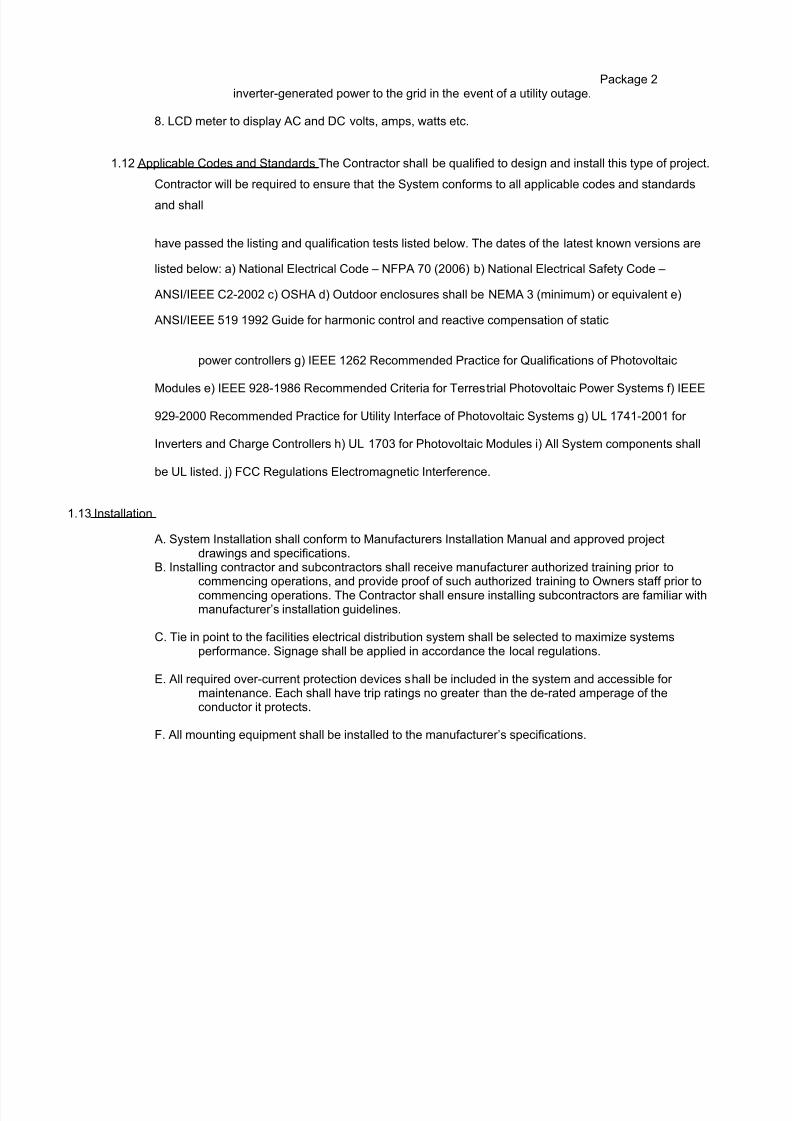
Package 2inverter-generated power to the grid in the event of a utility outage.
8. LCD meter to display AC and DC volts, amps, watts etc.
1.12 Applicable Codes and Standards The Contractor shall be qualified to design and install this type of project.
Contractor will be required to ensure that the System conforms to all applicable codes and standards
and shall
have passed the listing and qualification tests listed below. The dates of the latest known versions are
listed below: a) National Electrical Code – NFPA 70 (2006) b) National Electrical Safety Code –
ANSI/IEEE C2-2002 c) OSHA d) Outdoor enclosures shall be NEMA 3 (minimum) or equivalent e)
ANSI/IEEE 519 1992 Guide for harmonic control and reactive compensation of static
power controllers g) IEEE 1262 Recommended Practice for Qualifications of Photovoltaic
Modules e) IEEE 928-1986 Recommended Criteria for Terrestrial Photovoltaic Power Systems f) IEEE
929-2000 Recommended Practice for Utility Interface of Photovoltaic Systems g) UL 1741-2001 for
Inverters and Charge Controllers h) UL 1703 for Photovoltaic Modules i) All System components shall
be UL listed. j) FCC Regulations Electromagnetic Interference.
1.13 Installation
A. System Installation shall conform to Manufacturers Installation Manual and approved projectdrawings and specifications.
B. Installing contractor and subcontractors shall receive manufacturer authorized training prior tocommencing operations, and provide proof of such authorized training to Owners staff prior tocommencing operations. The Contractor shall ensure installing subcontractors are familiar withmanufacturer’s installation guidelines.
C. Tie in point to the facilities electrical distribution system shall be selected to maximize systemsperformance. Signage shall be applied in accordance the local regulations.
E. All required over-current protection devices shall be included in the system and accessible for maintenance. Each shall have trip ratings no greater than the de-rated amperage of theconductor it protects.
F. All mounting equipment shall be installed to the manufacturer’s specifications.
8/3/2019 PVP Specs
http://slidepdf.com/reader/full/pvp-specs 9/12
Package 2
G. Installation should be organized and neat. Module connections and wiring should be neatly preparedand easily accessed by service persons.
H. All cables, conduit, exposed conductors, and electrical boxes should be secured and supportedaccording to code requirements.
I. System switching equipment shall have convenient access for resetting or repair during electricaloutages.
J. Site shall be maintained and kept secure, free of excessive debris and in safe condition during theconstruction period.
L. Special attention shall be paid to minimizing the risk from exposed fasteners, sharp edges, andpotential damage to the modules or support structures. Corrosion resistance and durability of the mechanical hardware shall be emphasized – the use of stainless steel fasteners andaluminum support structures are required. The use of ferrous metals, wood, or plasticcomponents is not acceptable.
1.14 Delivery, Storage and Handling of Materials
A. Deliver PV modules and system components to their final locations in protective wrappings,containers, and other protection that will exclude dirt and moisture and prevent damage fromconstruction operations. Remove protection only after equipment is safe from such hazards.
B. Modules may be delivered in containers that can be easily supported by the roof. Contractor shallinsure proper placement of point loads on the roof for equipment staging and installation.
C. Contractor shall maintain the integrity of the roof surface during delivery, handling and installation,including laying out mats, insulation/plywood layers, etc. Any damage to the roof surface shallbe identified and repaired by the Contractor.
D. Each module shall be visually inspected for defects by the Contractor and the Engineer prior toinstallation.
E. PV modules shall be free of dirt and construction debris prior to system start up procedures.
1.15 System Commissioning
A. Commissioning Plan shall include checklists and verifications in the following Project Phases: Design,Installation, Operation (Function and Performance Checks), and Turn Over.
B. System inspection and safety checks: Contractor shall run through a checklist of startup requirementsand conduct a series of safety tests to ensure proper installation, safe operation and specifiedperformance.
C. The Engineer must be present during the commissioning process. Final acceptance of thecommissioning process will be by the Engineer.
D. String voltage and current readings
1. Voltages will be recorded for each string, each sub-array, and the entire array Package 2
8/3/2019 PVP Specs
http://slidepdf.com/reader/full/pvp-specs 10/12
using calibrated instrumentation. Measurements will be recorded and provided to the Owner in aclear, tabular format. Each voltage measurement will include the following ancillary data: thedate; the time of day that the measurement was taken; the ambient temperature at the time; andthe solar irradiation at the time. The strings that make up each sub-array will be clearly identifiedon a drawing by number.
2. After inverter startup, current shall be recorded for each string, each sub-array, and the entire array.Measurements will be recorded and provided to the Owner in a clear, tabular format. Each
voltage measurement will include the following ancillary data: the date; the time of day that themeasurement was taken; the ambient temperature at the time; and the solar irradiation at thetime. The strings that make up each sub-array will be clearly identified on a drawing by number.
E. All inverter startup tests as specified by the inverter manufacturer in the inverter operation manual andconducted by a factory-authorized technician.
a. Actual power vs. predicted power b. Measure Voc of every source circuit and log itc. Measure ac power and compare to predicted power d. Verify tightness of all wiring terminationse. Verify proper marking and labeling of all wire terminations and enclosuresf. Verify shut-down proceduresg. Verify start-up (“wake-up”) proceduresh. Verify system 5-minute delay upon re-starti. Verify PV array quick connectors are fully mated and wires neatly secured
j. Verify no debris on the modules, no damaged or broken modulesk. Verify Total Harmonic Distortion and Power Factor
F. System Performance Testing
1. Contractor shall conduct a two hour performance test of each array to verify that rated performance is met.2. The test must be conducted between on a clear sunny day during peak sun isolation periods (between 11 amand 1 pm). Test readings shall be manually recorded, including:a. Sun isolation (5 minute intervals)b. Ambient air temperature (5 minute intervals)c. Wind speed (5 minute intervals)d. System kW AC output (5 minute interval)e. Array DC voltage, current and power (5 minute intervals)f. String currents (once over the two hour test)
g. Solar module surface temperature (minimum 4 locations – 5 minute intervals)h. Inverter information (15 minute intervals)3. From the data, the following shall be calculated:a. kWdc output, corrected to PTCb. System AC output, corrected to PTCc. Inverter tested efficiency4. Contractor shall furnish a detailed report summarizing the test.
5. If it is found that the system cannot meet the stated performance, contractor must furnish additional solar panels to meet this condition, and repeat
8/3/2019 PVP Specs
http://slidepdf.com/reader/full/pvp-specs 11/12
Package 2performance testing as required.
G. Documentation
1. Prepare five (5) copies of operating and maintenance manuals in hard cover binders anddeliver to the Engineer. As a minimum the Contractor shall include:
a. A complete set of all approved submittals including shop drawings and product literature.b. As built roof plans showing the final placement of all panels, combiner boxes, connections, and conduitplacement.
c. As built electrical plans, including three line diagrams, and elevation drawings showing the final placement of the electrical equipment.
d. Cleaning instructions for the PV panels.
e. Copies of all start-up procedure measurements.
f. Copies of all testing data and reports.
g. Troubleshooting Guidelines.
h. System maintenance schedule and procedures.i. Contact information for technical assistance and parts ordering. I. Training
1Provide copies of a training manual for operation and maintenance of the PV System.
2Conduct an onsite training class including a minimum four hours of instruction. Training must be providedby factory-authorized representatives of the System Equipment. Proof of such authorization must beprovided to the Engineer prior to commencing the training.
1.16 Warranties and Service
A. Warrantees
The Contractor must provide warranties on both the completed System and the individualcomponents. The methods for implementing the Terms and Conditions of the warranty must beclearly established, and handled by the Contractor throughout the term of the warranty period,
the following warranties are required:
1Special warranties specified in this Article shall not deprive Owner of other rights Owner may have under other provisions of the Contract Documents and shall be in addition to, and run concurrent with, other warrantiesmade by Contractor under requirements of the Contract Documents.
2The overall system shall be warranted by the Contractor for a minimum period of five (5) years. SeparateManufacturer warrantees will be passed
8/3/2019 PVP Specs
http://slidepdf.com/reader/full/pvp-specs 12/12
Package 2through to owner.
1PV modules shall have a one year workmanship warranty that guarantees full module replacement as a resultof defective workmanship. Modules shall have a power warranty that guarantees power output to be within 10%of original power during the first 10 years of operation and 20% of original output during years 11 through 20 of operation.2Mounting System – Manufacturer shall warrant the mounting system hardware to be free from defects in
material and workmanship for a period of five (5) years.3Inverters - Manufacturer shall warrant the mounting system hardware to be free from defects in material andworkmanship for a period of five (5) years and include an extended warranty for an additional five (5) years.
B. Service
1. Qualifications
a. Contractor shall be locally based, and have in-house first response technicianscertified by panel and inverter manufacturer. Contractor shall demonstratelocally based service capabilities on the Project Team Organization Chart.
2. During the period of warranty, Contractor shall conduct and document all recommendedpreventative maintenance. Preventative maintenance shall include the following and be
performed no less than annually by direct qualified employees of the Contractor:
a. Visual and mechanical inspection of all equipment
b. Random checking of mounting system operation
c. Verification of electrical dc continuity via ammeter readings
d. Inspection and replacement of all fuses.
e. A Preventative Maintenance plan shall be submitted to the Engineer for review and approval prior to beingincluded as part of the O&M Manual.
1.17 On-site Supply of Spare Materials
The Contractor shall leave a supply of System materials on-site that match the products that are
installed in the System as follows:
a) Fuses. (1) For every (10) of each type and rating, but not less than (1) of each;
b) Indicator Lamps. (2) For every (6) of each type and size, but not less than (2) of each;
c) Inverters. (1) For each model used in the System;
d) DC Disconnect Switches. (1) For each model used in the System.