pwi convention 2016 - the unsung heroes
TRANSCRIPT

The PWI is proudly supported by its hero members
2016 Permanent Way Institution Sydney Annual Convention
The UNSUNG Heroes
The UNSUNG Heroes
Background of Permanent Way Institution NSW Inc.
The Institution was formed in 1884 in England by a group of dedicated railway men, who were responsiblefor development of railway track across the British Isles, and who felt the need for an avenue for exchangeof track design, construction and maintenance. They realised the educational and social value ofcommunications between all levels of men engaged on the railway tracks and associated structures.The safety of rail travel has been brought to the present standards because of a better understanding of thebehaviour of the tracks under load; the Institution has played a vital part in gaining this understanding.Realising this, the New South Wales section was formed in 1974, not only to benefit from those who hadgone before, but also to add to the development of still more efficient rail transportation in the years ahead.
Attending the Luncheon and Happy Hour
Members, particularly those in New South Wales, are reminded of the responsibilities legislated underthe Rail Safety Act 2008 with regard to the definition of “rail safety worker”. Members also need toconsider respective employer drug and alcohol policies.
DisclaimerThe views expressed by authors and/or presenters are not necessarily the view of the PWI Committee orPWI Members.
THE NSW PWI IS PROUDLY SUPPORTED BY ITS GOLD CORPORATE MEMBERS
2016 Journal Table of Contents
FIRST SESSION – CPB CONTRACTORS
COBAR PRIVATE RAIL NETWORK LONG TERM 1
PERFORMANCE OF A PIONEERING TRACK STRUCTURE
WELDING - THE PERMANENT WAY 11
2016 WELDERS AWARD 22
2016 YOUNG ACHIEVER AWARD 23
ADVERTISEMENTS
Enhanced Corporate
and Corporate Member
Advertisements 80
SECOND SESSION - JOHN HOLLAND GROUPGAME DAY LEADERSHIP - BUILDING A GENERATIVE 27
CULTURE OF LEADERS
AUSTRALIA’S ENGINEERING HERITAGE - LIFE EXTENSION 30
OF THE SYDNEY CENTRAL FLYING JUNCTION
NEW TRACK SLAB ALTERNATIVE - THE GAME 40
CHANGER FOR AUSTRALIA’S RAIL INDUSTRY
2016 ALAN BARHAM MAINTENANCE TEAM AWARD 51
PRESIDENT’S WELCOME I
GENERAL
PWI 2016/2017 NSW COMMITTEE III
EMERGENCY PROCEDURES
2016 CONVENTION PROGRAM
THE UNSUNG HEROES IV
2016/2017 ENHANCED & CORPORATE MEMBERS
PLATINUM MEMBERS V
GOLD MEMBERS VI
SILVER MEMBERS VII
CORPORATE MEMBERS VIII
PWI 2017 GOLF DAY XIV
PWI 2017 WINTER DINNER
THIRD SESSION - Bill Killinger
THE UNSUNG HEROES - Open Panel Forum 2016 59
2016 Ken Erickson Innovation Award 61
2016 Steve Maxwell Platelaying Award 64
THIRD SESSION - Bill KillingerTHIRD SESSION - Bill KillingerTHIRD SESSION - Bill KillingerTHIRD SESSION - Bill KillingerTHIRD SESSION - Bill KillingerTHIRD SESSION - Bill KillingerTHIRD SESSION - Bill KillingerTHIRD SESSION - Bill KillingerTHIRD SESSION - Bill KillingerTHIRD SESSION - Bill KillingerTHIRD SESSION - Bill KillingerTHIRD SESSION - Bill KillingerTHIRD SESSION - Bill KillingerTHIRD SESSION - Bill KillingerTHIRD SESSION - Bill KillingerTHIRD SESSION - Bill KillingerTHIRD SESSION - Bill Killinger
THE UNSUNG HEROES - Open Panel Forum 2016 59THE UNSUNG HEROES - Open Panel Forum 2016 59THE UNSUNG HEROES - Open Panel Forum 2016 59THE UNSUNG HEROES - Open Panel Forum 2016 59THE UNSUNG HEROES - Open Panel Forum 2016 59THE UNSUNG HEROES - Open Panel Forum 2016 59THE UNSUNG HEROES - Open Panel Forum 2016 59THE UNSUNG HEROES - Open Panel Forum 2016 59THE UNSUNG HEROES - Open Panel Forum 2016 59THE UNSUNG HEROES - Open Panel Forum 2016 59THE UNSUNG HEROES - Open Panel Forum 2016 59THE UNSUNG HEROES - Open Panel Forum 2016 59THE UNSUNG HEROES - Open Panel Forum 2016 59THE UNSUNG HEROES - Open Panel Forum 2016 59THE UNSUNG HEROES - Open Panel Forum 2016 59
2016 Ken Erickson Innovation Award 612016 Ken Erickson Innovation Award 612016 Ken Erickson Innovation Award 612016 Ken Erickson Innovation Award 612016 Ken Erickson Innovation Award 612016 Ken Erickson Innovation Award 612016 Ken Erickson Innovation Award 612016 Ken Erickson Innovation Award 612016 Ken Erickson Innovation Award 612016 Ken Erickson Innovation Award 612016 Ken Erickson Innovation Award 612016 Ken Erickson Innovation Award 612016 Ken Erickson Innovation Award 612016 Ken Erickson Innovation Award 612016 Ken Erickson Innovation Award 612016 Ken Erickson Innovation Award 61
2016 Steve Maxwell Platelaying Award 642016 Steve Maxwell Platelaying Award 642016 Steve Maxwell Platelaying Award 642016 Steve Maxwell Platelaying Award 642016 Steve Maxwell Platelaying Award 642016 Steve Maxwell Platelaying Award 642016 Steve Maxwell Platelaying Award 642016 Steve Maxwell Platelaying Award 642016 Steve Maxwell Platelaying Award 642016 Steve Maxwell Platelaying Award 642016 Steve Maxwell Platelaying Award 642016 Steve Maxwell Platelaying Award 642016 Steve Maxwell Platelaying Award 642016 Steve Maxwell Platelaying Award 642016 Steve Maxwell Platelaying Award 642016 Steve Maxwell Platelaying Award 642016 Steve Maxwell Platelaying Award 642016 Steve Maxwell Platelaying Award 642016 Steve Maxwell Platelaying Award 642016 Steve Maxwell Platelaying Award 642016 Steve Maxwell Platelaying Award 642016 Steve Maxwell Platelaying Award 64
Welcome to the Annual Convention 2016
O C T O B E R I 2 0 1 6
i
Welcome to the 2016 NSW Permanent Way Institution Annual Convention
It’s my pleasure to extend a warm welcome to all our special guests from Industry and Government, our panel of speakers and all our award entrants who have joined us today.
To those attending their fi rst PWI Convention, we’re delighted to have you here. We are particularly pleased to again welcome those Engineering students attending our convention. I trust members will seek them out to encourage their interest in becoming part of the ‘railway family’.
I hope all delegates will derive a great benefi t from attending this year’s Convention. You will gain knowledge of what is happening in the industry and you will get the opportunity to build relationships with key industry players. Our corporate members continue to recognise the PWI as the peak rail track industry body and continue to provide the fi nancial support needed to keep it there. We again thank them for that!
It is my pleasure to personally acknowledge our Keynote Speaker, Glenn Bentley the Chief Executive Offi cer of Altrac Light Rail for agreeing to provide our keynote address this morning. Glenn has been in the Rail Industry for many years. Glenn started his career as a cadet engineer working for State Rail Authority and he spent a number of years working in Hong Kong for Barclay Mowlem. He was the Program Director of the Rail Clearways program for the Transport Infrastructure Development Corporation before moving to his current role running the Sydney Light Rail.
Todays’ conference theme is “The Unsung Heroes”. The theme in essence is a tribute to small and medium enterprises and subject matter experts (collectively the SME’s) that underpin the industry. The rail industry, like many, can be seen as a playground for big business and these big organisations often get all the acclaim and recognition for their successes.
However, there is often a large number of small to medium size rail businesses and dedicated individuals that sit behind these organisations whom often go unnoticed. These “unsung heroes” may include technical specialists, specialist material and equipment suppliers, skilled resources or simply those individuals whom, through their tireless dedication to the industry have made contributions to the success of their client organisations or clients’ businesses. This year’s conference will be an opportunity to put the spotlight on some of these SME’s.
Following on from the success of last year’s panel session, Bill Killinger AM will again chair the session after lunch. Bill will further explore with a broad cross section of people from the rail industry what drew them to the industry and ask who inspired them to stay in the industry. We will hear some great stories and also explore some of their memorable moments.
We continue to see an unprecedented number of major rail projects coming to the market and challenging the industry’s ability to support and deliver these projects. The project include, light rail, heavy rail, new metro’s and will provide transformational benefi ts to the major cities.
We have also seen a fundamental shift, particularly in NSW, towards having a fully integrated transport system. The customer continues to be the central focus and there is a strong push on modal changes to get the best public transport solution.
The importance of an effective and integrated freight network is also driving the separation of freight and passenger rail in our metropolitan areas, new intermodal facilities, and the proposed Inland Rail link linking the port of Melbourne and Brisbane will be key game changes for the country.
The NSW Section of the Permanent Way Institution is still one of the strongest and most vibrant groups of rail minded members in the PWI worldwide. This success has been achieved through the excellent and well attended events arranged by a tireless committee and the signifi cant material and fi nancial support provided by our Corporate Members.
Our Enhanced Corporate Members and Corporate Members enable us to make our events affordable allowing as many of our personal members to participate as possible. The support we receive has enabled the Committee to offer the best value one day Convention, six Technical Meetings in Sydney and at least two regional meetings per year as well as a Winter Dinner and Golf Day. On your behalf, I wish to thank the hard-working committee, volunteers, sponsors and others who have worked to make the PWI’s activities during the year such a wonderful success. With such enthusiasm, the PWI can only become stronger and more effective in providing a forum for the exchange of information and ideas for the rail industry. I urge you to make the most of this valuable day, take the opportunity to catch up with old friends and colleagues in the networking sessions at morning tea and lunch and enjoy what should be another excellent PWI Conference.
Mark Harris
President NSW PWI
O C T O B E R I 2 0 1 6
ii
We continue to see an unprecedented number of major rail projects coming to
the market and challenging the industry’s ability to support and deliver these
projects. The project include, light rail, heavy rail, new metro’s and will provide
transformational benefi ts to the major cities.
PWI 2016/17 Committee
O C T O B E R I 2 0 1 6
iii
Committee Members Peter Boonstra Sarah-Ann Brennan Mark Butler
Scott Chapman Sam Cook Gillian Cottle
Kevin Golledge Sal Haider Michael Hickey
Paul Hitchings Ken Lingabala Steve Naumovski
Mike O’Shea Zane Sell Julian Sharp
David Spiteri Jason Tagg Mark White
Life Members Allan Pidgeon Barry Lees David Bull
David Roberts Dennis Dobson Don Hagarty
Glenn Dewberry John Gorman Ken Sherwood
Ken Swan Kevin Ryan Mark Harris
Michael Hickey Tania Page William Fowler
President Mark Harris
Treasurer Claudine O’Donoghue
Secretary Patrick Man
Editor Mark Xerri
Membership Secretary Stuart Sutherland
Website Manager Daniel Collison
Please take a few moments to familiarise yourself with the following emergency procedures:
• Observe the locations of emergency exits and assembly points that are advertised inside the venue
• If the alarm sounds, or a dangerous incident takes place, please follow instructions from staff or voice-over
• A strict no smoking policy is enforced both inside and outside the venue
Drugs and Alcohol
• For those of you who are classified as Rail Safety Workers under the Rail National Safety Law and who are ‘on duty’ please be aware that the Drug and Alcohol provisions of the Act apply whilst attending this Convention.
• The Institution is committed to the responsible service of alcohol and expects all delegates to be moderate in their alcohol consumption.
The Evacuation Alarm
• Alert alarm (BEEP BEEP BEEP) – prepare to evacuate
• Evacuation alarm (WHOOP WHOOP WHOOP) – Evacuate and follow voice-over instructions
• When the evacuation alarm sounds, evacuate by nearest exit and head to assembly point
• Assembly point is the open area on palm grove or in front of Harbourside, wait here for further instructions from staff
Security
Delegates leaving the venue at any time after the morning session will not be re-admitted unless special arrangements are made with a Committee Member.
Emergency Procedures
O C T O B E R I 2 0 1 6
iv
2016 Convention Program
FRIDAY 28 OCTOBER 2016 – Dockside Pavilion, Darling Harbour
From 07.15 Registration Desk Open
08.15 – 08.20 Welcome Address NSW President Mark Harris
08.20 – 08.45 Keynote Address Glenn Bentley, CEO, Altrac Light Rail
SESSION 1 Chaired by CPB Contractors
08:50 – 09.10 Cobar Private Network Long Term Performance Phillip Imrie / Jessica Fallico, Plateway of a Pioneering Track Structure
09:10 – 09:30 Welding – The Permanent Way Shamus Walsh, Hardface Technologys
09:30 – 09:50 Discussion / Questions for all papers Session Chair
09:50 – 10.10 Welders Award Presentation Mark White
10.10 – 10.30 Young Achiever Award 2016 Presentation Mike Hickey
10.30 – 11.15 MORNING TEA
SESSION 2 Chaired by John Holland
11.15 – 11.35 Game Day Leadership – Building a Generative Treaven Martinus / Craig Boothroyd, Culture of Leaders Martinus Rail
11.35 – 11.55 Australia’s Engineering Heritage – Life Extension of Debra McLaughlin / Rose Emslie the Sydney Central Flying Junction Lorenz Eberl, Jacobs
11.55 – 12.15 New Track Slab Alternative – The Game Changer Henrik Vocks, Rhomberg Rail for Australia’s Rail Industry
12.15 – 12.30 Discussion / Questions for all papers Session Chair
12.30 – 12.50 Alan Barham Maintenance Award Ken Lingabala
12.50 – 14.30 LUNCH
SESSION 3 Bill Killinger A.M.
14.30 – 15.30 The Unsung Heroes - Panel Session Bill Killinger A.M.
15.30 – 15.50 Ken Erickson Innovation Award Mike Hickey
15.50 – 16.50 Steve Maxwell Platelaying Award Stephen Fleck
16.50 – 17.00 Endnote and Announcements NSW President Mark Harris
AFTER PARTY Proudly sponsored by
17:00 – 19.00 Extended Happy Hour and Canapes

The UNSUNG Heroes
The UNSUNG Heroes
O C T O B E R I 2 0 1 6
v
2016/2017 Enhanced Corporate Members
The PWI recognises the continued support we receive from our Enhanced Platinum Members:
Platinum Corporate Members
2016/2017 Enhanced Gold Corporate Members
O C T O B E R I 2 0 1 6
vi
Gold Corporate Members
The PWI recognises the continued support we receive from our Enhanced Gold Members.
O C T O B E R I 2 0 1 6
vii
2016/2017 Enhanced SILVER Corporate Members
Silver Corporate Members
The PWI recognises the continued support we receive from our Enhanced Silver Members.
ARCHSERVICES
2016/2017 Corporate Members
O C T O B E R I 2 0 1 6
viii
PWI NSW would like to thank all its Corporate Members for their support. We look forward to your continued sponsorship in the future.
Advisian
Agonis Group
Anric Rail
Aquenta Consulting
Arcadis Australia Pacifi c
Arenco
Australian Rail Track Corporation
Beca Pty Ltd
BloorRail Pty Ltd
Cardno Hard & Forester
CGC Recruitment
CH2M HILL
CR Rail
Degnan Constructions
Delkor Rail Pty Ltd
Downer Group
Edilon Sedra Australia
Fluor Global Services
Gartner Rose Pty Ltd
Geofabrics Australasia Pty Ltd
GHD Pty Ltd
Harbinger Infrastructure
InfraSol Group Pty Ltd
Jacobs
Kellogg Brown & Root
KH1 - Robel
Liftronic Pty Ltd
Linmag Rail Service
Martinus Rail
McLachlan Lister Hill International
Meadows Consulting Pty Ltd
Mott MacDonald
Multi Civil & Rail Services Pty Ltd
Northern Fencing Specialists
Pidgeon Civil Engineering
Plateway Pty Ltd
Progress Rail Services
Projex Group Pty Ltd
Rail, Tram & Bus Union NSW
Railtech Australia Limited
Rhomberg Rail Australia
Robson Civil Projects
Rocla Concrete Sleepers
RRPS Pty Ltd
RT Health Fund
Select Encompass
Sine Industries
SLR Consulting
Sydney Trains
Taylor Rail Australia
Thermit Australia Pty Ltd
Union Railtrack & Industrial Supplies Pty Ltd
VAE Railway Systems Pty Ltd
VizionX Group
Vossloh Cogifer Australia
Glenreagh Mountain Railway Inc. (Associate Corporate)
O C T O B E R I 2 0 1 6
ix
2016/2017 Corporate Members
2016/2017 Corporate Members
O C T O B E R I 2 0 1 6
x
O C T O B E R I 2 0 1 6
xi
2016/2017 Corporate Members
2016/2017 Corporate Members
O C T O B E R I 2 0 1 6
xii
SINE INDUSTRIES
O C T O B E R I 2 0 1 6
xiii
2016/2017 Corporate Members
xiv
Chairman: CPB Contractors
Paper 1: Cobar Private Rail Network Long Term Performance
of a Pioneering Track Structure
Phillip Imrie, Principal, Plateway
Jessica Fallico, Project Engineer, Plateway
Paper 2: Welding – The Permanent Way
Shamus Walsh, General Manager, Hardface Technologys
2016 Welders Award Presentation
2016 Young Achiever Award Presentation
First SessionFirst
SessionPWI Annual Convention 2016
COBAR PRIVATE RAIL NETWORK LONG TERM PERFORMANCE OF A PIONEERING TRACK STRUCTUREPhillip Imrie (Principal, Plateway), Jessica Fallico (Project Engineer, Plateway)
F I R S T S E S S I O N I COBAR PRIVATE RAIL NETWORK LONG TERM PERFORMANCE OF A PIONEERING TRACK STRUCTURE
1
Introduction
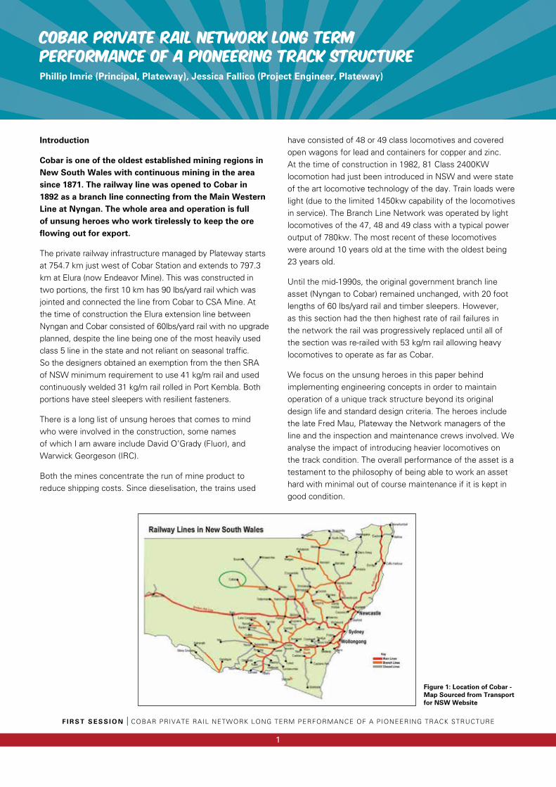
Cobar is one of the oldest established mining regions in New South Wales with continuous mining in the area since 1871. The railway line was opened to Cobar in 1892 as a branch line connecting from the Main Western Line at Nyngan. The whole area and operation is full of unsung heroes who work tirelessly to keep the ore flowing out for export.
The private railway infrastructure managed by Plateway starts at 754.7 km just west of Cobar Station and extends to 797.3 km at Elura (now Endeavor Mine). This was constructed in two portions, the first 10 km has 90 lbs/yard rail which was jointed and connected the line from Cobar to CSA Mine. At the time of construction the Elura extension line between Nyngan and Cobar consisted of 60lbs/yard rail with no upgrade planned, despite the line being one of the most heavily used class 5 line in the state and not reliant on seasonal traffic. So the designers obtained an exemption from the then SRA of NSW minimum requirement to use 41 kg/m rail and used continuously welded 31 kg/m rail rolled in Port Kembla. Both portions have steel sleepers with resilient fasteners.
There is a long list of unsung heroes that comes to mind who were involved in the construction, some names of which I am aware include David O’Grady (Fluor), and Warwick Georgeson (IRC).
Both the mines concentrate the run of mine product to reduce shipping costs. Since dieselisation, the trains used
have consisted of 48 or 49 class locomotives and covered open wagons for lead and containers for copper and zinc. At the time of construction in 1982, 81 Class 2400KW locomotion had just been introduced in NSW and were state of the art locomotive technology of the day. Train loads were light (due to the limited 1450kw capability of the locomotives in service). The Branch Line Network was operated by light locomotives of the 47, 48 and 49 class with a typical power output of 780kw. The most recent of these locomotives were around 10 years old at the time with the oldest being 23 years old.
Until the mid-1990s, the original government branch line asset (Nyngan to Cobar) remained unchanged, with 20 foot lengths of 60 lbs/yard rail and timber sleepers. However, as this section had the then highest rate of rail failures in the network the rail was progressively replaced until all of the section was re-railed with 53 kg/m rail allowing heavy locomotives to operate as far as Cobar.
We focus on the unsung heroes in this paper behind implementing engineering concepts in order to maintain operation of a unique track structure beyond its original design life and standard design criteria. The heroes include the late Fred Mau, Plateway the Network managers of the line and the inspection and maintenance crews involved. We analyse the impact of introducing heavier locomotives on the track condition. The overall performance of the asset is a testament to the philosophy of being able to work an asset hard with minimal out of course maintenance if it is kept in good condition.
Figure 1: Location of Cobar - Map Sourced from Transport for NSW Website
F I R S T S E S S I O N I COBAR PRIVATE RAIL NETWORK LONG TERM PERFORMANCE OF A PIONEERING TRACK STRUCTURE
2
Background of Track Structure and Design
The track between CSA Junction (763.840km) and Elura (Endeavor) Mine Yard (797.340km) was constructed in 1982, for the purpose of transporting lead and zinc with a planned annual run of mine production of around 5 million gross tonnes. The track has been designed with the concept to be built “Cost effective in terms of the traffic that moves over it” (Hay, 1982). With this in mind the track was built with a minimum capital cost and a unique configuration of continuously welded 31kg/m rail with steel sleepers for a design life of 15 years.
One significance of this configuration between CSA Junction and Elura, was that the track was designed for an axle load of 19t, while 31kg/m rail was generally only used elsewhere in Australia for an axle loading of up to 16t with fishplated rail joints. To further reduce the initial expenditure for construction, a wide sleeper spacing of 710mm was adopted. Both the rail and the sleeper spacing exceeded the SRA’s standard at the time. This was based on the criteria of a short design life of 15 years to reflect the associated predicted mine life. The design is an example of an effective track system using a “light section railway to carry a low annual tonnage under a medium axle loading” (O’’Grady, 1983). 48 class locomotives operated over the line for 31 years, well beyond the design life of the track. Given the light track
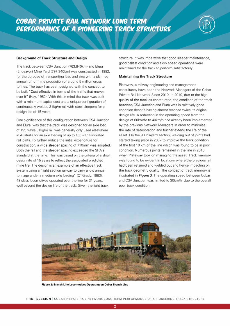
structure, it was imperative that good sleeper maintenance, good ballast condition and slow speed operations were maintained for the track to perform satisfactorily.
Maintaining the Track Structure
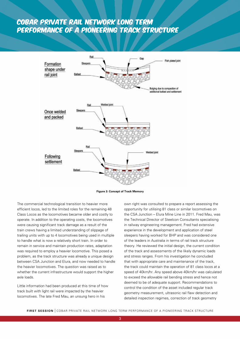
Plateway, a railway engineering and management consultancy have been the Network Managers of the Cobar Private Rail Network Since 2010. In 2010, due to the high quality of the track as constructed, the condition of the track between CSA Junction and Elura was in relatively good condition despite having almost reached twice its original design life. A reduction in the operating speed from the design of 60km/hr to 40km/h had already been implemented by the previous Network Managers in order to minimise the rate of deterioration and further extend the life of the asset. On the 90 lbs/yard section, welding out of joints had started taking place in 2007 to improve the track condition of the first 10 km of the line which was found to be in poor condition. Numerous joints remained in the line in 2010 when Plateway took on managing the asset. Track memory was found to be evident in locations where the previous rail had been retained and welded out and hence impacting on the track geometry quality. The concept of track memory is illustrated in Figure 3. The operating speed between Cobar and CSA Junction was limited to 30km/hr due to the overall poor track condition.
COBAR PRIVATE RAIL NETWORK LONG TERM PERFORMANCE OF A PIONEERING TRACK STRUCTURE
Figure 2: Branch Line Locomotives Operating on Cobar Branch Line
COBAR PRIVATE RAIL NETWORK LONG TERM PERFORMANCE OF A PIONEERING TRACK STRUCTURE
F I R S T S E S S I O N I COBAR PRIVATE RAIL NETWORK LONG TERM PERFORMANCE OF A PIONEERING TRACK STRUCTURE
3
The commercial technological transition to heavier more efficient locos, led to the limited roles for the remaining 48 Class Locos as the locomotives became older and costly to operate. In addition to the operating costs, the locomotives were causing significant track damage as a result of the train crews having a limited understanding of slippage of trailing units with up to 4 locomotives being used in multiple to handle what is now a relatively short train. In order to remain in service and maintain production rates, adaptation was required to employ a heavier locomotive. This posed a problem, as the track structure was already a unique design between CSA Junction and Elura, and now needed to handle the heavier locomotives. The question was raised as to whether the current infrastructure would support the higher axle loads.
Little information had been produced at this time of how track built with light rail were impacted by the heavier locomotives. The late Fred Mau, an unsung hero in his
own right was consulted to prepare a report assessing the opportunity for utilising 81 class or similar locomotives on the CSA Junction – Elura Mine Line in 2011. Fred Mau, was the Technical Director of Steelcon Consultants specialising in railway engineering management. Fred had extensive experience in the development and application of steel sleepers having worked for BHP and was considered one of the leaders in Australia in terms of rail track structure theory. He reviewed the initial design, the current condition of the track and assessments of the likely dynamic loads and stress ranges. From his investigation he concluded that with appropriate care and maintenance of the track, the track could maintain the operation of 81 class locos at a speed of 40km/hr. Any speed above 40km/hr was calculated to exceed the allowable rail bending stress and hence not deemed to be of adequate support. Recommendations to control the condition of the asset included regular track geometry measurement, ultrasonic rail flaw detection and detailed inspection regimes, correction of track geometry
Figure 3: Concept of Track Memory
F I R S T S E S S I O N I COBAR PRIVATE RAIL NETWORK LONG TERM PERFORMANCE OF A PIONEERING TRACK STRUCTURE
4
COBAR PRIVATE RAIL NETWORK LONG TERM PERFORMANCE OF A PIONEERING TRACK STRUCTURE
faults and variance, as well as replacing any rail flaw defects. The report highlighted the fact that track management must act together with train operation in order to maintain operation of the asset.
In response to the report, Plateway adopted a maintenance strategy which involved the following;
1) Restore/improve the track condition between CSA and CSA Junction.
2) Implement an inspection regime for early detection of poor track condition and rail faults.
3) Undertake remedial action to rectify defects as they occur.
The inspection regime included detailed inspections, track geometry recording using the AK Car, ultrasonic rail flaw detection and stress free temperature measurements which were to be conducted annually. The AK car was a method of monitoring the track geometry and identifying locations with overall poor track condition. Fred Mau recommended that the standard deviation for top from the AK car inspection should be maintained to keep the standard deviation to 3mm or below. This meant that the PCI, the third standard deviation should remain under 9 for both top and twist.
AK Car Analysis
The track condition index (TCI) from the AK car results have been monitored in consecutive years since 2011. TCI provides an overall indication of the condition of the track variance of top, line, twist and gauge. TCI increases with time and tonnage. Smaller values of TCI mean smaller dynamic loads, rail stresses and track deflection and hence the aim was to maintain TCI levels to the lowest level possible. The limits for TCI’s and PCI’s for maintenance were obtained from John Hollands Engineering Standard CRN CS 210. These limits are said to be debatable as to whether these values actually provide a sufficient track condition or whether it is the bare minimum of track condition. The use of the TCI values, provides a means to identify sections of track in need of attention for maintenance. Implementing maintenance when and where it is required, extends the life of the components of the track and becomes a very cost effective solution. Deterioration in track can be increased by even small misalignments in top and line resulting in increasing forces and hence it is imperative that the track geometry is monitored and faults rectified once they occur.
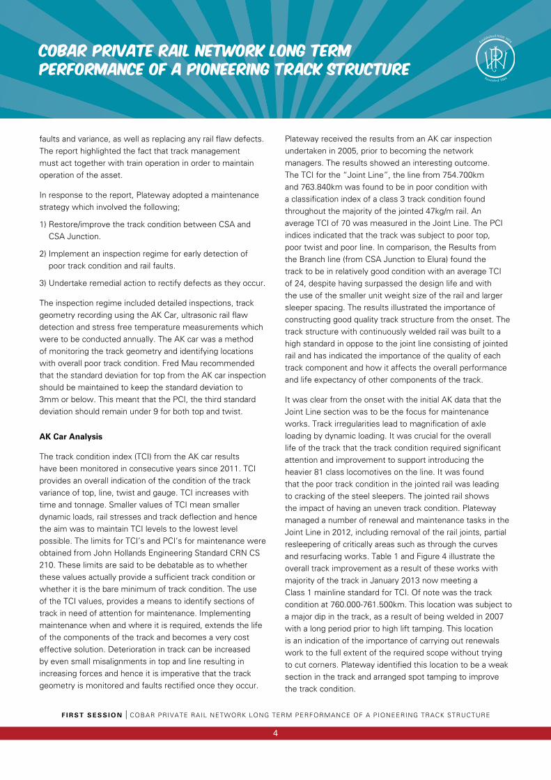
Plateway received the results from an AK car inspection undertaken in 2005, prior to becoming the network managers. The results showed an interesting outcome. The TCI for the “Joint Line”, the line from 754.700km and 763.840km was found to be in poor condition with a classification index of a class 3 track condition found throughout the majority of the jointed 47kg/m rail. An average TCI of 70 was measured in the Joint Line. The PCI indices indicated that the track was subject to poor top, poor twist and poor line. In comparison, the Results from the Branch line (from CSA Junction to Elura) found the track to be in relatively good condition with an average TCI of 24, despite having surpassed the design life and with the use of the smaller unit weight size of the rail and larger sleeper spacing. The results illustrated the importance of constructing good quality track structure from the onset. The track structure with continuously welded rail was built to a high standard in oppose to the joint line consisting of jointed rail and has indicated the importance of the quality of each track component and how it affects the overall performance and life expectancy of other components of the track.
It was clear from the onset with the initial AK data that the Joint Line section was to be the focus for maintenance works. Track irregularities lead to magnification of axle loading by dynamic loading. It was crucial for the overall life of the track that the track condition required significant attention and improvement to support introducing the heavier 81 class locomotives on the line. It was found that the poor track condition in the jointed rail was leading to cracking of the steel sleepers. The jointed rail shows the impact of having an uneven track condition. Plateway managed a number of renewal and maintenance tasks in the Joint Line in 2012, including removal of the rail joints, partial resleepering of critically areas such as through the curves and resurfacing works. Table 1 and Figure 4 illustrate the overall track improvement as a result of these works with majority of the track in January 2013 now meeting a Class 1 mainline standard for TCI. Of note was the track condition at 760.000-761.500km. This location was subject to a major dip in the track, as a result of being welded in 2007 with a long period prior to high lift tamping. This location is an indication of the importance of carrying out renewals work to the full extent of the required scope without trying to cut corners. Plateway identified this location to be a weak section in the track and arranged spot tamping to improve the track condition.
COBAR PRIVATE RAIL NETWORK LONG TERM PERFORMANCE OF A PIONEERING TRACK STRUCTURE
F I R S T S E S S I O N I COBAR PRIVATE RAIL NETWORK LONG TERM PERFORMANCE OF A PIONEERING TRACK STRUCTURE
5
Table 1: Total TCI Classification Comparison for Joint Line
Figure 4: Comparison of TCI Classification
F I R S T S E S S I O N I COBAR PRIVATE RAIL NETWORK LONG TERM PERFORMANCE OF A PIONEERING TRACK STRUCTURE
6
COBAR PRIVATE RAIL NETWORK LONG TERM PERFORMANCE OF A PIONEERING TRACK STRUCTURE
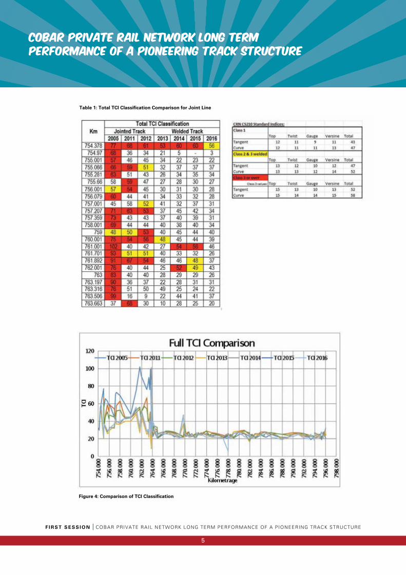
The overall track condition of the Joint Line significantly improved since Plateway took the lead in the challenging role of restoring the track and becoming the network managers. With the completion of CWR in mid 2012, the track condition had majority of the line in a class 1 condition from the 2013 AK inspection results. The question now reflected back to whether the track could handle the heavier locomotives and remain viable for the years to come. May 2013 was the day the unsung heroes of Plateway introduced the first trial of the 2400 kW locomotive from Cobar to Elura. The asset appeared to perform well and was concluded through close observation on the first cab ride out to the Endeavor Mine that the line was adequate to run the heavier locomotives. Use of the 47kg/m rail and the 31kg/m rail
under the new operating condition requires high standard of asset condition to be maintained. With the continual maintenance throughout the track, the AK results have found that the track condition index has be maintained and has even decreased in sections of the track over the years. The average TCI for each year inspection was determined and compared in Figure 6. The AK data results conclude that by addressing faults as they arise and undertake maintenance works in the at risk locations, the track was considered to be adequate to maintain operation of the heavier 81 Class Loco’s. Of interesting note, is that the 31kg/m rail has only required very minimal maintenance input to keep the track in good condition.
Figure 6: Average TCI for Joint Line and Branch Line
Figure 5: 81 Class Locomotive Operating on Cobar Branch Line
7
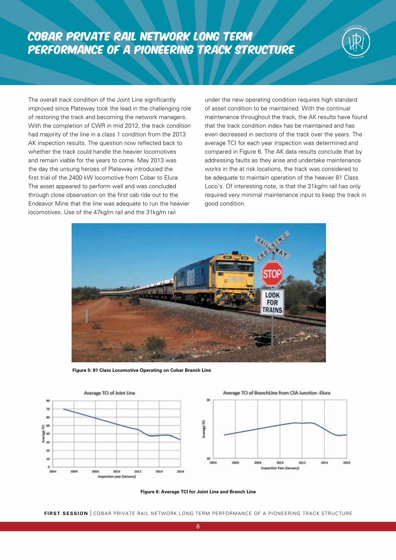
Grinding and resurfacing were carried out in 2015 in the Joint Line section. Improvement in the track condition from these works are reflected in the TCI data in Table 1. The current condition of the Joint line is now almost all compliant with class 1 values of TCI. Since the grinding works were undertaken shortly after the tamping works, we were not able to obtain the individual influence of each set of the works on the track condition. We do know that the roughness of the track is increased by surface defects, which transmit the impacts and vibrations through to the ballast leading to ballast migration from the pods of the steel sleepers. The surface condition of the rail was subject to wheel burns, corrugations, pitting and gauge face checking. The track was ground between 754.700km and 763.800km with the exception of the section between 759.400km and 761.500km which were not covered in the grinding works. The PCI data for the different geometry parameters including top, twist, gauge and line were compared between the 2015 and 2016 AK data results.
The top in the Joint Line of the 2016 data has improved from the 2015 data and can now be classified as a class 1 condition with the exception of between 759.993km and 761.711km where the track was not ground. While the top had improved as a result from the resurfacing works in this location, it had not been restored to the level of a class 1 track the remainder of the track had achieved. This provides an indication of the effectiveness of the grinding works and improvement in the top PCI.
Fred Mau proposed that the condition of the top should be maintained to a PCI of 9 in the 31kg/m rail due the track being subject to high stresses. The majority of the Branch
Line from CSA Junction to Elura has maintained this level of track condition for top. There is however a segment of track between 769.740km and 769.993km in curved track which reaches a PCI of 12 for top due to a level crossing renewal. This section of track had been subject to tamping in 2015, which has resulted in a reduction in PCI of 2 for Top.
While the resurfacing works saw some improvement in the twist of the track, the section between 757.999km and 761.711km still remains in poor condition for twist with a PCI of up to 19 identified. This section of track has seen continuous issues in the line, which can be linked back to the track memory of the jointed rail.
Maintenance work has found to be a risk itself to the track condition. While maintenance works are carried out to improve the track condition and remove defects, it can also result in deterioration of the roughness of the track and can also lead to defects or failures. This was evident with a number of misaligned welds in the track and even a broken weld which occurred in 2015 requiring emergency maintenance to restore the broken rail.
Analysis of the track condition relies on the inspection method to collect the data. The state of the condition has relied on the AK Car data collection and the ability to remove any shifting in data. While the AK car sets a definitive starting point and track segments for measure PCI and TCI values, the data is subject to longitudinal offsets. It is imperative to ensure the most adequate comparisons of data are obtained as offsets can lead to false conclusions of one segment improving while the other is deteriorating. While the use of the PCI and TCI parameters in segments assists in determining locations requiring attention for maintenance, it is limited by the fact the segment is generally much longer than the clusters of rough sections found in the track.
Through Plateway’s detailed inspections we collect as much detail as possible to establish measurable asset condition components. It can be difficult to define repeatable conditional indexes for the components of the track in terms of establishing deterioration rates and conditional standards. Plateway utilises a track geometry trolley, which allows the track geometry to be monitored and can be benchmarked to the results obtained from the AK Car inspections. Plateway has been able to monitor the rail for wear using a Mini Prof device. Measurements from the Mini Prof have indicated
F I R S T S E S S I O N I COBAR PRIVATE RAIL NETWORK LONG TERM PERFORMANCE OF A PIONEERING TRACK STRUCTURE
COBAR PRIVATE RAIL NETWORK LONG TERM PERFORMANCE OF A PIONEERING TRACK STRUCTURE

F I R S T S E S S I O N I COBAR PRIVATE RAIL NETWORK LONG TERM PERFORMANCE OF A PIONEERING TRACK STRUCTURE
8
COBAR PRIVATE RAIL NETWORK LONG TERM PERFORMANCE OF A PIONEERING TRACK STRUCTURE
that the 31 kg/m rail is has minimal wear with a loss of height of only around 1.3mm. The measured profile is compared to the standard 31kg/m rail profile in Figure 7.
Figure 7: Rail Profile of 31kg/m Branch Line
Ultrasonic Analysis
The 31kg/m rail was purchased from BHP which was rolled at the Port Kembla Steel mill, which at the time was in the process of shutting down production of long sections. The steel from Port Kembla was of poor quality compared with the current production from Whyalla. The steel contains significant inclusions and rolling defects as a result and this has been reflected in the ultrasonic inspection results with a number of internal defects identified in the rail over the years. This was important to monitor as the steel was subject to high rail bending stresses. The Washington State Department of Transportation, determined the moment of inertia for each rail size and made a comparison of the different size rail. The higher the stiffness of the rail, results in reduced deflection in the rail. Comparison shows that the 47kg/m rail is approximately 190% stiffer than the 31kg/m rail. The results from the track condition index provided evidence that the track structure was performing well under the 81 class locos as a result of an established good foundation. We will now focus on the internal rail defects in the track, and how the heavier loading has impacted.
Washington State Department of Transportation
Impacts of Heavy Axle Loads On light density Lines in the state of Washington
February 2001 Ken Casavant & Denver Tolliver
Figure 8: Relationship between Rail Weight and Stiffness
As a preventative measure for rail breaks, ultrasonic inspections have been scheduled annually since Plateway took over the network manager role. The ultrasonic inspection not only provides a means of identifying internal defects for removal, but has also provided a means to benchmark the condition of the asset for the continuity of service. The rate at which rail flaws occur give an indication of the rate of fatigue.
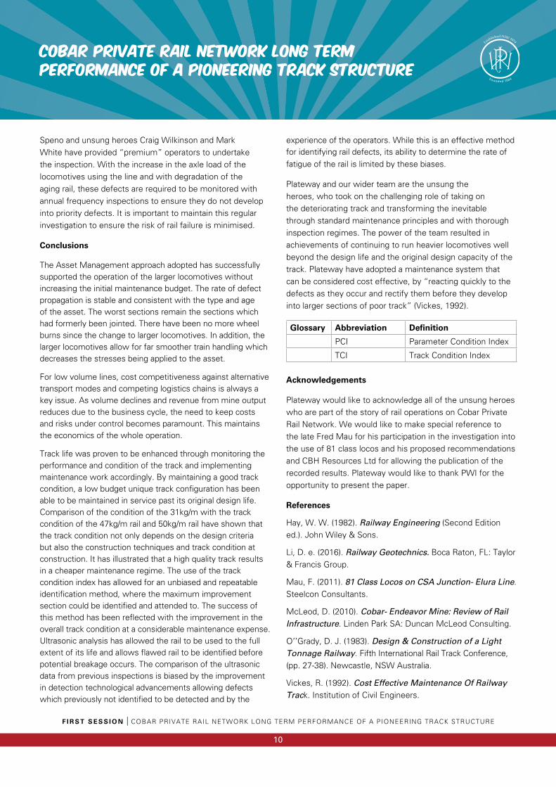
The Ultrasonic inspection detects both significant defects requiring removal and insignificant defects which require monitoring only to ensure they do not develop further. The results of the Significant Defects can be found in Figure 9. The first ultrasonic inspection was undertaken in 2011 and detected a large number of defects, as a result from insufficient frequency of inspections undertaken. Defects detected include Transverse, scatter crack, vertical spit head and horizontal split webs. The defects detected have been separated into the two separate parts of the line, Cobar to CSA Junction and CSA Junction to Elura. As can be seen from the results, majority of the defects were found in the 31kg/m rail from CSA Junction to Elura, which reflects upon both the poor quality of the rail and the use of light rail. After the initial inspection in 2011, only one small significant defect has been detected in the Joint Line in the past 5 years.
COBAR PRIVATE RAIL NETWORK LONG TERM PERFORMANCE OF A PIONEERING TRACK STRUCTURE
F I R S T S E S S I O N I COBAR PRIVATE RAIL NETWORK LONG TERM PERFORMANCE OF A PIONEERING TRACK STRUCTURE
9
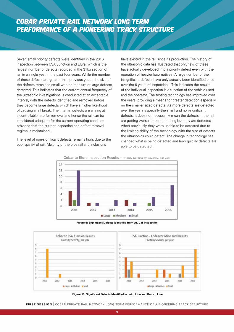
Seven small priority defects were identified in the 2016 inspection between CSA Junction and Elura, which is the largest number of defects recorded in the 31kg section of rail in a single year in the past four years. While the number of these defects are greater than previous years, the size of the defects remained small with no medium or large defects detected. This indicates that the current annual frequency of the ultrasonic investigations is conducted at an acceptable interval, with the defects identified and removed before they become large defects which have a higher likelihood of causing a rail break. The internal defects are arising at a controllable rate for removal and hence the rail can be considered adequate for the current operating condition provided that the current inspection and defect removal regime is maintained.
The level of non-significant defects remains high, due to the poor quality of rail. Majority of the pipe rail and inclusions
have existed in the rail since its production. The history of the ultrasonic data has illustrated that only few of these have actually developed into a priority defect even with the operation of heavier locomotives. A large number of the insignificant defects have only actually been identified once over the 6 years of inspections. This indicates the results of the individual inspection is a function of the vehicle used and the operator. The testing technology has improved over the years, providing a means for greater detection especially on the smaller sized defects. As more defects are detected over the years especially the small and non-significant defects, it does not necessarily mean the defects in the rail are getting worse and deteriorating but they are detected when previously they were unable to be detected due to the limiting ability of the technology with the size of defects the ultrasonics could detect. The change in technology has changed what is being detected and how quickly defects are able to be detected.
Figure 10: Significant Defects Identified in Joint Line and Branch Line
Figure 9: Significant Defects Identified from AK Car Inspection
Cobar to Elura Inspection Results – Priority Defects by Severity, per year
F I R S T S E S S I O N I COBAR PRIVATE RAIL NETWORK LONG TERM PERFORMANCE OF A PIONEERING TRACK STRUCTURE
10
COBAR PRIVATE RAIL NETWORK LONG TERM PERFORMANCE OF A PIONEERING TRACK STRUCTURE
Speno and unsung heroes Craig Wilkinson and Mark White have provided “premium” operators to undertake the inspection. With the increase in the axle load of the locomotives using the line and with degradation of the aging rail, these defects are required to be monitored with annual frequency inspections to ensure they do not develop into priority defects. It is important to maintain this regular investigation to ensure the risk of rail failure is minimised.
Conclusions
The Asset Management approach adopted has successfully supported the operation of the larger locomotives without increasing the initial maintenance budget. The rate of defect propagation is stable and consistent with the type and age of the asset. The worst sections remain the sections which had formerly been jointed. There have been no more wheel burns since the change to larger locomotives. In addition, the larger locomotives allow for far smoother train handling which decreases the stresses being applied to the asset.
For low volume lines, cost competitiveness against alternative transport modes and competing logistics chains is always a key issue. As volume declines and revenue from mine output reduces due to the business cycle, the need to keep costs and risks under control becomes paramount. This maintains the economics of the whole operation.
Track life was proven to be enhanced through monitoring the performance and condition of the track and implementing maintenance work accordingly. By maintaining a good track condition, a low budget unique track configuration has been able to be maintained in service past its original design life. Comparison of the condition of the 31kg/m with the track condition of the 47kg/m rail and 50kg/m rail have shown that the track condition not only depends on the design criteria but also the construction techniques and track condition at construction. It has illustrated that a high quality track results in a cheaper maintenance regime. The use of the track condition index has allowed for an unbiased and repeatable identification method, where the maximum improvement section could be identified and attended to. The success of this method has been reflected with the improvement in the overall track condition at a considerable maintenance expense. Ultrasonic analysis has allowed the rail to be used to the full extent of its life and allows flawed rail to be identified before potential breakage occurs. The comparison of the ultrasonic data from previous inspections is biased by the improvement in detection technological advancements allowing defects which previously not identified to be detected and by the
experience of the operators. While this is an effective method for identifying rail defects, its ability to determine the rate of fatigue of the rail is limited by these biases.
Plateway and our wider team are the unsung the heroes, who took on the challenging role of taking on the deteriorating track and transforming the inevitable through standard maintenance principles and with thorough inspection regimes. The power of the team resulted in achievements of continuing to run heavier locomotives well beyond the design life and the original design capacity of the track. Plateway have adopted a maintenance system that can be considered cost effective, by “reacting quickly to the defects as they occur and rectify them before they develop into larger sections of poor track” (Vickes, 1992).
Glossary Abbreviation Definition
PCI Parameter Condition Index
TCI Track Condition Index
Acknowledgements
Plateway would like to acknowledge all of the unsung heroes who are part of the story of rail operations on Cobar Private Rail Network. We would like to make special reference to the late Fred Mau for his participation in the investigation into the use of 81 class locos and his proposed recommendations and CBH Resources Ltd for allowing the publication of the recorded results. Plateway would like to thank PWI for the opportunity to present the paper.
References
Hay, W. W. (1982). Railway Engineering (Second Edition ed.). John Wiley & Sons.
Li, D. e. (2016). Railway Geotechnics. Boca Raton, FL: Taylor & Francis Group.
Mau, F. (2011). 81 Class Locos on CSA Junction- Elura Line. Steelcon Consultants.
McLeod, D. (2010). Cobar- Endeavor Mine: Review of Rail Infrastructure. Linden Park SA: Duncan McLeod Consulting.
O’’Grady, D. J. (1983). Design & Construction of a Light Tonnage Railway. Fifth International Rail Track Conference, (pp. 27-38). Newcastle, NSW Australia.
Vickes, R. (1992). Cost Effective Maintenance Of Railway Track. Institution of Civil Engineers.
Welding - The permanent wayShamus Walsh, General Manager, Hardface Technologys
F I R S T S E S S I O N I W E L D I N G – T H E P E R M A N E N T W A Y
11
Overview
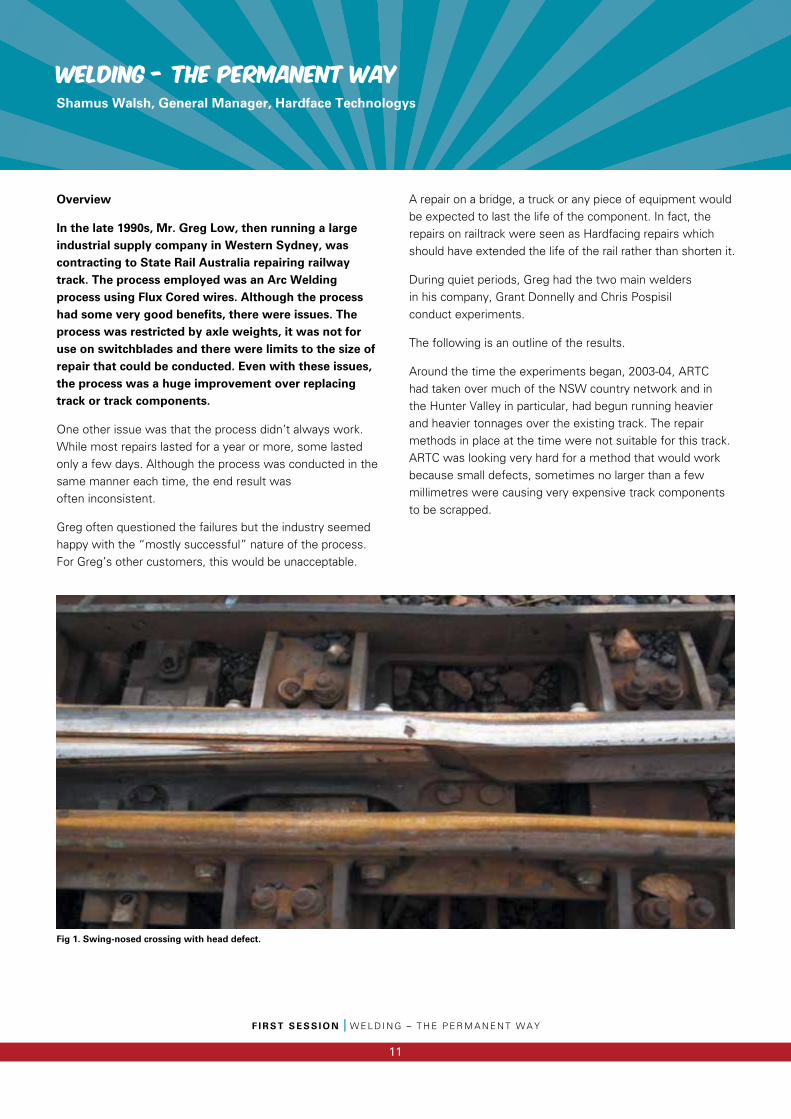
In the late 1990s, Mr. Greg Low, then running a large industrial supply company in Western Sydney, was contracting to State Rail Australia repairing railway track. The process employed was an Arc Welding process using Flux Cored wires. Although the process had some very good benefits, there were issues. The process was restricted by axle weights, it was not for use on switchblades and there were limits to the size of repair that could be conducted. Even with these issues, the process was a huge improvement over replacing track or track components.
One other issue was that the process didn’t always work. While most repairs lasted for a year or more, some lasted only a few days. Although the process was conducted in the same manner each time, the end result was often inconsistent.
Greg often questioned the failures but the industry seemed happy with the “mostly successful” nature of the process. For Greg’s other customers, this would be unacceptable.
A repair on a bridge, a truck or any piece of equipment would be expected to last the life of the component. In fact, the repairs on railtrack were seen as Hardfacing repairs which should have extended the life of the rail rather than shorten it.
During quiet periods, Greg had the two main welders in his company, Grant Donnelly and Chris Pospisil conduct experiments.
The following is an outline of the results.
Around the time the experiments began, 2003-04, ARTC had taken over much of the NSW country network and in the Hunter Valley in particular, had begun running heavier and heavier tonnages over the existing track. The repair methods in place at the time were not suitable for this track. ARTC was looking very hard for a method that would work because small defects, sometimes no larger than a few millimetres were causing very expensive track components to be scrapped.
Fig 1. Swing-nosed crossing with head defect.
F I R S T S E S S I O N I W E L D I N G – T H E P E R M A N E N T W A Y
12
Welding - The permanent way
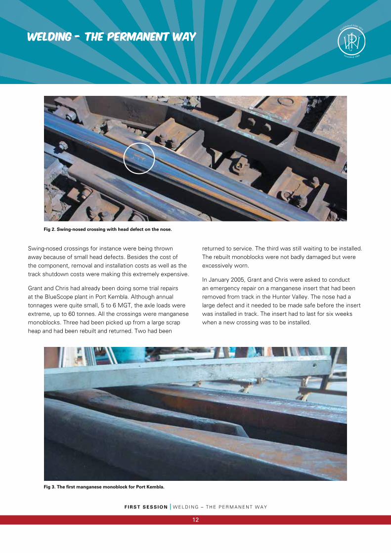
Swing-nosed crossings for instance were being thrown away because of small head defects. Besides the cost of the component, removal and installation costs as well as the track shutdown costs were making this extremely expensive.
Grant and Chris had already been doing some trial repairs at the BlueScope plant in Port Kembla. Although annual tonnages were quite small, 5 to 6 MGT, the axle loads were extreme, up to 60 tonnes. All the crossings were manganese monoblocks. Three had been picked up from a large scrap heap and had been rebuilt and returned. Two had been
returned to service. The third was still waiting to be installed. The rebuilt monoblocks were not badly damaged but were excessively worn.
In January 2005, Grant and Chris were asked to conduct an emergency repair on a manganese insert that had been removed from track in the Hunter Valley. The nose had a large defect and it needed to be made safe before the insert was installed in track. The insert had to last for six weeks when a new crossing was to be installed.
Fig 2. Swing-nosed crossing with head defect on the nose.
Fig 3. The first manganese monoblock for Port Kembla.
Welding - The permanent way
F I R S T S E S S I O N I W E L D I N G – T H E P E R M A N E N T W A Y
13
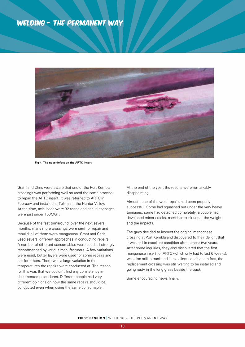
Grant and Chris were aware that one of the Port Kembla crossings was performing well so used the same process to repair the ARTC insert. It was returned to ARTC in February and installed at Telarah in the Hunter Valley.At the time, axle loads were 32 tonne and annual tonnages were just under 100MGT.
Because of the fast turnaround, over the next several months, many more crossings were sent for repair and rebuild, all of them were manganese. Grant and Chris used several different approaches in conducting repairs. A number of different consumables were used, all strongly recommended by various manufacturers. A few variations were used, butter layers were used for some repairs and not for others. There was a large variation in the temperatures the repairs were conducted at. The reason for this was that we couldn’t find any consistency in documented procedures. Different people had very different opinions on how the same repairs should be conducted even when using the same consumable.
At the end of the year, the results were remarkably disappointing.
Almost none of the weld repairs had been properly successful. Some had squashed out under the very heavy tonnages, some had detached completely, a couple had developed minor cracks, most had sunk under the weight and the impacts.
The guys decided to inspect the original manganese crossing at Port Kembla and discovered to their delight that it was still in excellent condition after almost two years. After some inquiries, they also discovered that the first manganese insert for ARTC (which only had to last 6 weeks), was also still in track and in excellent condition. In fact, the replacement crossing was still waiting to be installed and going rusty in the long grass beside the track.
Some encouraging news finally.
Fig 4. The nose defect on the ARTC insert.
F I R S T S E S S I O N I W E L D I N G – T H E P E R M A N E N T W A Y
14
Welding - The permanent way
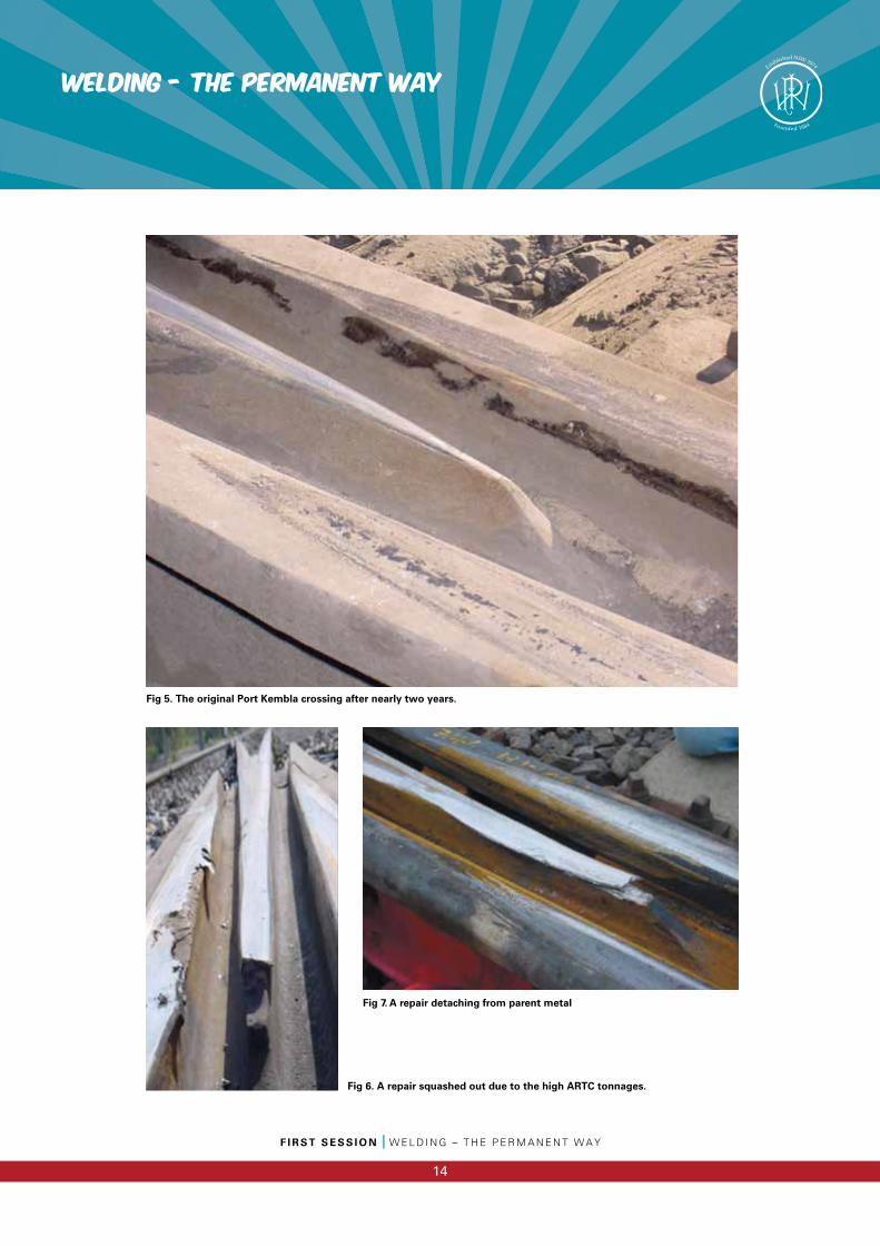
Fig 5. The original Port Kembla crossing after nearly two years.
Fig 6. A repair squashed out due to the high ARTC tonnages.
Fig 7. A repair detaching from parent metal
Welding - The permanent way
F I R S T S E S S I O N I W E L D I N G – T H E P E R M A N E N T W A Y
15
At this point, ARTC became directly involved and a formalised research plan was put in place.
So far, we had only conducted repairs on manganese rail, no repairs had been conducted on steel rail.
Before field trials could take place for steel rail, laboratory tests had to be conducted to confirm what the consumable manufacturers were telling us.
This was an expensive process as an in-depth test cost about $2,500 each. Costs were shared for much of this testing. A lot of the testing was carried out by Bureau Veritas
in Newcastle. However, companies in Melbourne, Sydney and Perth were also involved. Two European consumable manufacturers paid for our test samples to be returned to their testing houses in Europe.
Again the results were remarkably disappointing.
Most of the test welds failed. The welds were too hard, too soft, full of martensite, full of porosity, slag inclusions, cracks or tears, lack of fusion and a dozen other problems.
Yet, these were consumables that we were told were very good for repairing railway tracks.
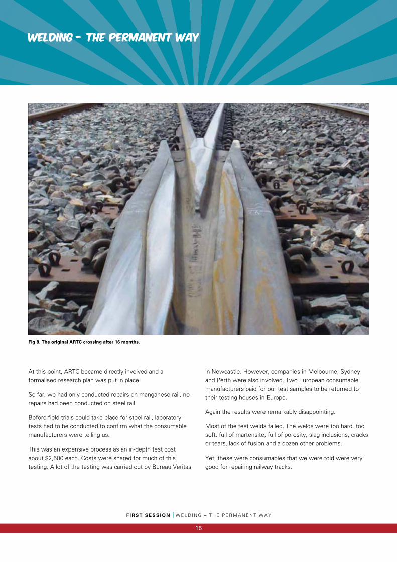
Fig 8. The original ARTC crossing after 16 months.
F I R S T S E S S I O N I W E L D I N G – T H E P E R M A N E N T W A Y
16
Welding - The permanent way
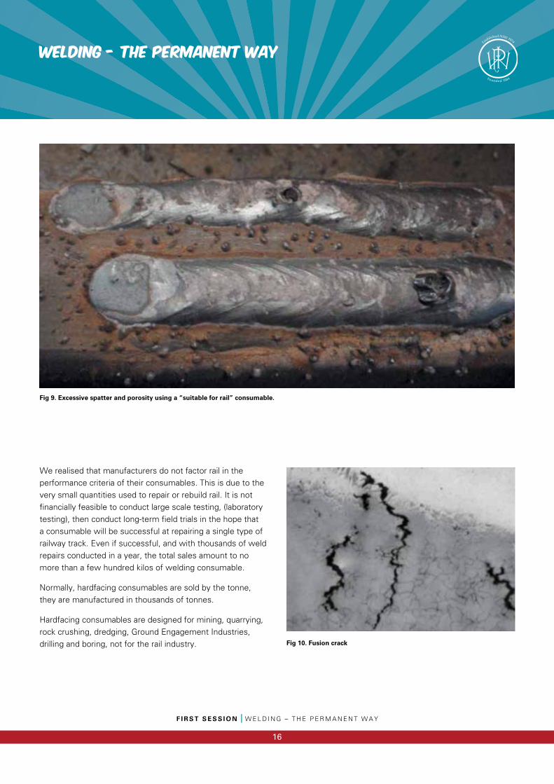
We realised that manufacturers do not factor rail in the performance criteria of their consumables. This is due to the very small quantities used to repair or rebuild rail. It is not financially feasible to conduct large scale testing, (laboratory testing), then conduct long-term field trials in the hope that a consumable will be successful at repairing a single type of railway track. Even if successful, and with thousands of weld repairs conducted in a year, the total sales amount to no more than a few hundred kilos of welding consumable.
Normally, hardfacing consumables are sold by the tonne, they are manufactured in thousands of tonnes.
Hardfacing consumables are designed for mining, quarrying, rock crushing, dredging, Ground Engagement Industries, drilling and boring, not for the rail industry.
Fig 9. Excessive spatter and porosity using a “suitable for rail” consumable.
Fig 10. Fusion crack
Welding - The permanent way
F I R S T S E S S I O N I W E L D I N G – T H E P E R M A N E N T W A Y
17
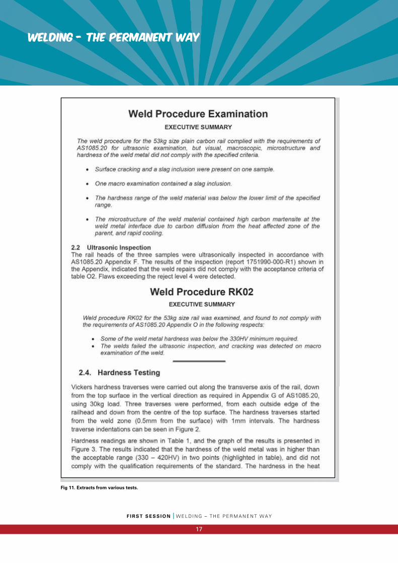
Fig 11. Extracts from various tests.
F I R S T S E S S I O N I W E L D I N G – T H E P E R M A N E N T W A Y
18
Welding - The permanent way
We also discovered that the manufacturer’s claims were not actually based on real life situations. When they were questioned about a particular consumable’s resistance to impacts, or ability to stop Rolling Contact Fatigue or resist gauge wear, we were met with blank stares. A few consumable manufacturers did supply some test results but these were from light rail or tram networks. In fact, the axle loads and annual tonnages we were working with didn’t exist in most of the world.
What we were trying to do had not actually been done before. We were on our own.
Luckily, not all the tests were failures. A few did pass. We were able to conduct field trials with several consumables.
Although laboratory tests are a very good way to determine the suitability of a consumable, process or technique for repairing rail, a successful test is not a guarantee that it will work in track.
A successful weld must still support millions of tonnes of freight, withstand millions of impacts, resist wear and cracking, must not suffer fatigue, must put up with heat and
cold, tension and compression stresses, and several other factors, none of which can be easily replicated in a laboratory and certainly not all at once.
A field test is the ultimate test. It is, however, a very slow test as we had to wait most of a year to determine how successful each test was. The longer a weld remained intact, the higher our hopes went, which also meant a bigger disappointment if it failed.
At times, the lack of progress was frustrating and disheartening. Often it seemed for every one step forward, the guys were taking two back.
Some people who supported us initially withdrew support as they didn’t believe what we were trying to do was actually possible.
However, there were successes and we were making progress although it was slow.
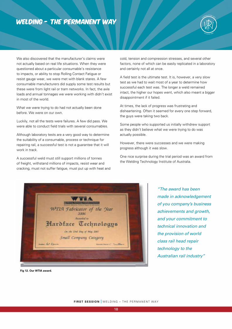
One nice surprise during the trial period was an award from the Welding Technology Institute of Australia.
Fig 12. Our WTIA award.
“The award has been
made in acknowledgement
of you company’s business
achievements and growth,
and your commitment to
technical innovation and
the provision of world
class rail head repair
technology to the
Australian rail industry”
Welding - The permanent way
F I R S T S E S S I O N I W E L D I N G – T H E P E R M A N E N T W A Y
19
Bit by bit, the guys worked out processes, techniques, consumables and so on for different types of rail.
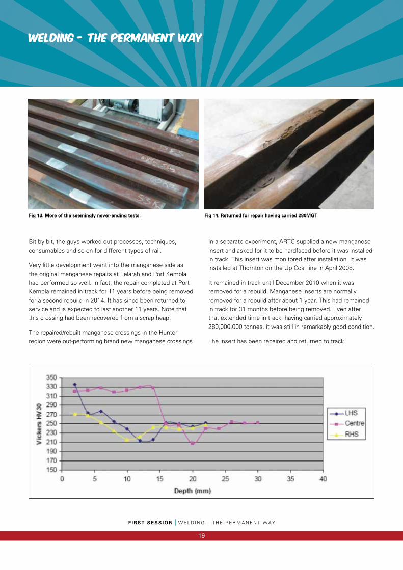
Very little development went into the manganese side as the original manganese repairs at Telarah and Port Kembla had performed so well. In fact, the repair completed at Port Kembla remained in track for 11 years before being removed for a second rebuild in 2014. It has since been returned to service and is expected to last another 11 years. Note that this crossing had been recovered from a scrap heap.
The repaired/rebuilt manganese crossings in the Hunter region were out-performing brand new manganese crossings.
In a separate experiment, ARTC supplied a new manganese insert and asked for it to be hardfaced before it was installed in track. This insert was monitored after installation. It was installed at Thornton on the Up Coal line in April 2008.
It remained in track until December 2010 when it was removed for a rebuild. Manganese inserts are normally removed for a rebuild after about 1 year. This had remained in track for 31 months before being removed. Even after that extended time in track, having carried approximately 280,000,000 tonnes, it was still in remarkably good condition.
The insert has been repaired and returned to track.
Fig 13. More of the seemingly never-ending tests. Fig 14. Returned for repair having carried 280MGT
F I R S T S E S S I O N I W E L D I N G – T H E P E R M A N E N T W A Y
20
Welding - The permanent way
Steel rail required much more input. One reason was that with manganese rail, we only had to deal with impact damage. Abrasion and RCF didn’t affect manganese crossings to a great extent. As well as this, austenitic manganese rail (Hadfield steel) has a fairly specific specification. It is very consistent.
While impacts still affected steel crossings, RCF was a big factor on plain steel rail and abrasion was a problem with switchblades and swing nosed crossings.
Another factor adding to the steel issue (unlike manganese) was that there were many different versions of steel in the rail industry. There were standard, head hardened and chrome vanadium steels, as well as several others with different metallurgical compositions. Added to this was the factor of ambient conditions. A repair in outback NSW on a very hot day required a completely different procedure to the exact same repair being conducted on a bitterly cold windy night in Melbourne.
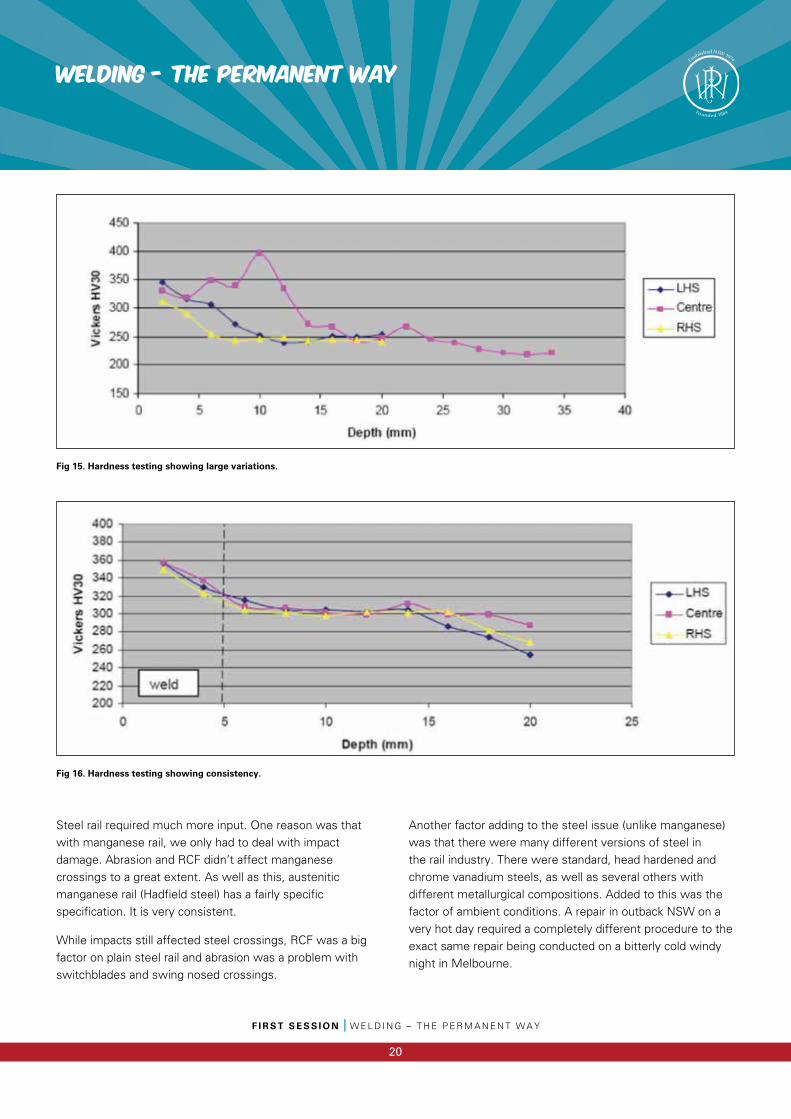
Fig 15. Hardness testing showing large variations.
Fig 16. Hardness testing showing consistency.
Welding - The permanent way
F I R S T S E S S I O N I W E L D I N G – T H E P E R M A N E N T W A Y
21
By the end of 2010 we had a method of repairing squats, cracks (TDs), wheelburns and other defects in plain rail. This method could cope with 100MGT per year with 32 tonne axle loads and we could give a guarantee or a warranty for five years on the repair.
We had a method of repairing switchblades and swing nosed crossings. The first switchblades we repaired in situ were completed at Thornton in November 2011. They were most recently inspected on 23rd April 2015 and were still in excellent condition. A warranty period of one year applied to these repairs.
Manganese crossing repairs were performing extremely well.
Steel crossing repairs were also performing brilliantly and coping with the extreme axle loads and tonnages even when repairs over 30mm deep were being conducted.
ARTC issued a Type Approval for the process and so as to separate or identify it from lesser processes, it was called Hedkote.
Grant and Chris got Hedkote licences numbered 001 and 002.
Since 2010 the process is now used all over Australia. The savings, particularly for Heavy Haul are enormous. In a single weekend, a few crews can literally save millions of dollars for a customer.
Research has not stopped either. Initially, on a manganese crossing for instance, a repair 300mm long was considered an extremely large repair. Now we regularly complete 3-meter-long repairs.
There are still challenges ahead, particularly some of the new Chinese rail. The rail is not easy to weld and because it is often used in heavy haul situations, the repairs must be perfect to cope with the conditions.
In 2014, Hardface exhibited at the Innotrans exhibition in Germany. The interest was surprising and has resulted in one overseas operation for Hardface with two other countries currently being set up.
As a result of the exhibition, Hardface was also nominated as a finalist in Germany’s Privatbahn Magazine’s Innovation Prize competition.
Repairing, rebuilding and recycling rail is now a very important part of many rail operator’s maintenance planning.
Little by little, and in the background, we’re changing the way rail is maintained.
In January 2005, Grant and Chris were asked to conduct an emergency repair on a
manganese insert that had been removed from track in the Hunter Valley. The nose had
a large defect and it needed to be made safe before the insert was installed in track.

The UNSUNG Heroes
The UNSUNG Heroes
2016 PWI Welders Award
F I R S T S E S S I O N I P W I W E L D E R S A W A R D
22
Nominations for 2016 PWI Welders Award
Judges
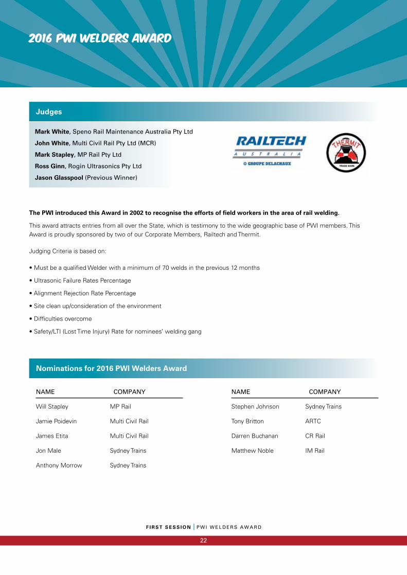
The PWI introduced this Award in 2002 to recognise the efforts of field workers in the area of rail welding.
This award attracts entries from all over the State, which is testimony to the wide geographic base of PWI members. This Award is proudly sponsored by two of our Corporate Members, Railtech and Thermit.
Judging Criteria is based on:
• Must be a qualifi ed Welder with a minimum of 70 welds in the previous 12 months
• Ultrasonic Failure Rates Percentage
• Alignment Rejection Rate Percentage
• Site clean up/consideration of the environment
• Diffi culties overcome
• Safety/LTI (Lost Time Injury) Rate for nominees’ welding gang
NAME COMPANY
Will Stapley MP Rail
Jamie Poidevin Multi Civil Rail
James Etita Multi Civil Rail
Jon Male Sydney Trains
Anthony Morrow Sydney Trains
NAME COMPANY
Stephen Johnson Sydney Trains
Tony Britton ARTC
Darren Buchanan CR Rail
Matthew Noble IM Rail
Mark White, Speno Rail Maintenance Australia Pty Ltd
John White, Multi Civil Rail Pty Ltd (MCR)
Mark Stapley, MP Rail Pty Ltd
Ross Ginn, Rogin Ultrasonics Pty Ltd
Jason Glasspool (Previous Winner)
F I R S T S E S S I O N I Y O U N G A C H I E V E R A W A R D
23
2016 YOUNG ACHIEVER AWARD
To be eligible for this award, an entrant must be 35 or younger at the 1 January of the year of entry. The Committee realise that this statement may bring some mirth. The aim is to gradually reduce the upper age limit to 30, once more younger members join. The proposed age limit of 35 allows more current members to be eligible.
Judging Criteria
Age: The entrant needs to be 35 or under at the 1st January of the year of entry.PWI Membership: The entrant needs to be a financial member of the PWI NSW at the time of entry.
Technical Paper or Presentation or Project or Program of Works
The Award will be judged on either a Technical Paper that has been written (and preferably presented) or a Project or Program of Works that has been completed, within the last 18 months.
Judging is based on:
Relevant Criteria Available Score
Relevance to Perway 20Difficulties Overcome 20Quality of Paper and/or Presentation 20Amount of Innovation 15Ongoing benefit to the rail industry 15Technical Excellence 10Total Score/Marks: 100
Award
Up to $10,000, to cover:
• Transport, registration, insurances and accommodation to a relevant railway conference (PWI approves the attendance at the nominated conference).
• Award must be taken within 2 years of being presented or agreement reached with the PWI Committee to be deferred for a longer period.
• The award may not be presented in a given year if entries are not considered suitable.
Conditions
Previous winners of this award (or similar such awards, e.g. the RTAA Frank Franklyn Award) will be excluded from re-submitting an application for this award for a period of no less than five years from the time of submitting their application for their winning award. The subject of the award must relate to the applicant’s current employer who will be required to provide a reference. The successful candidate will present at the next relevant Technical Meeting, a summary of the attended conference and any associated industry visits.
Michael Hickey, Life Member PWI
Lachlan Daniel, Mott McDonald
Geoff Wannan, GJW Management
Julian Sharp, CPB Contractors
David Spiteri, Transport for NSW
Judges
2016 YOUNG ACHIEVER AWARD
F I R S T S E S S I O N I Y O U N G A C H I E V E R A W A R D
24
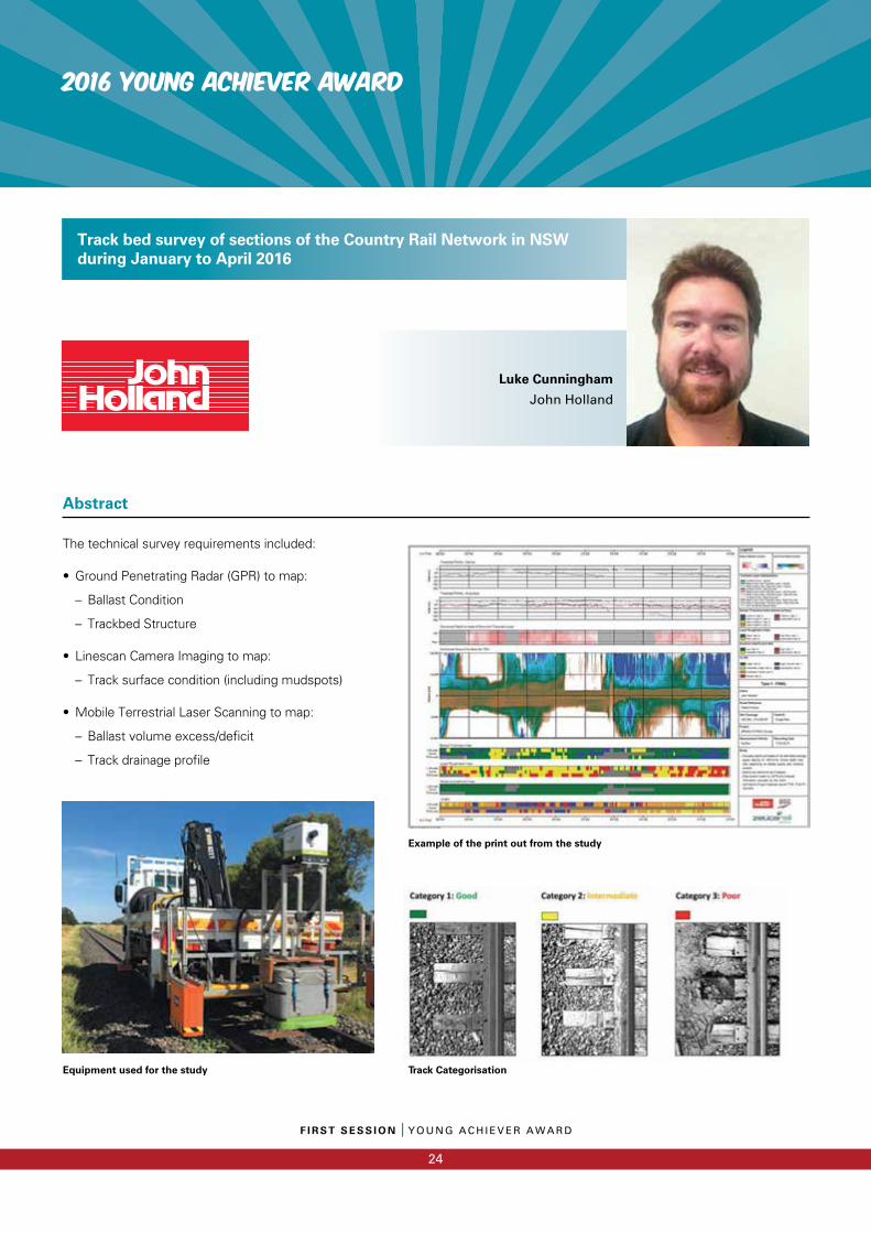
The technical survey requirements included:
• Ground Penetrating Radar (GPR) to map:
– Ballast Condition
– Trackbed Structure
• Linescan Camera Imaging to map:
– Track surface condition (including mudspots)
• Mobile Terrestrial Laser Scanning to map:
– Ballast volume excess/deficit
– Track drainage profile
Track bed survey of sections of the Country Rail Network in NSW during January to April 2016
Abstract
Luke CunninghamJohn Holland
Equipment used for the study
Example of the print out from the study
Track Categorisation
F I R S T S E S S I O N I Y O U N G A C H I E V E R A W A R D
25
2016 YOUNG ACHIEVER AWARD
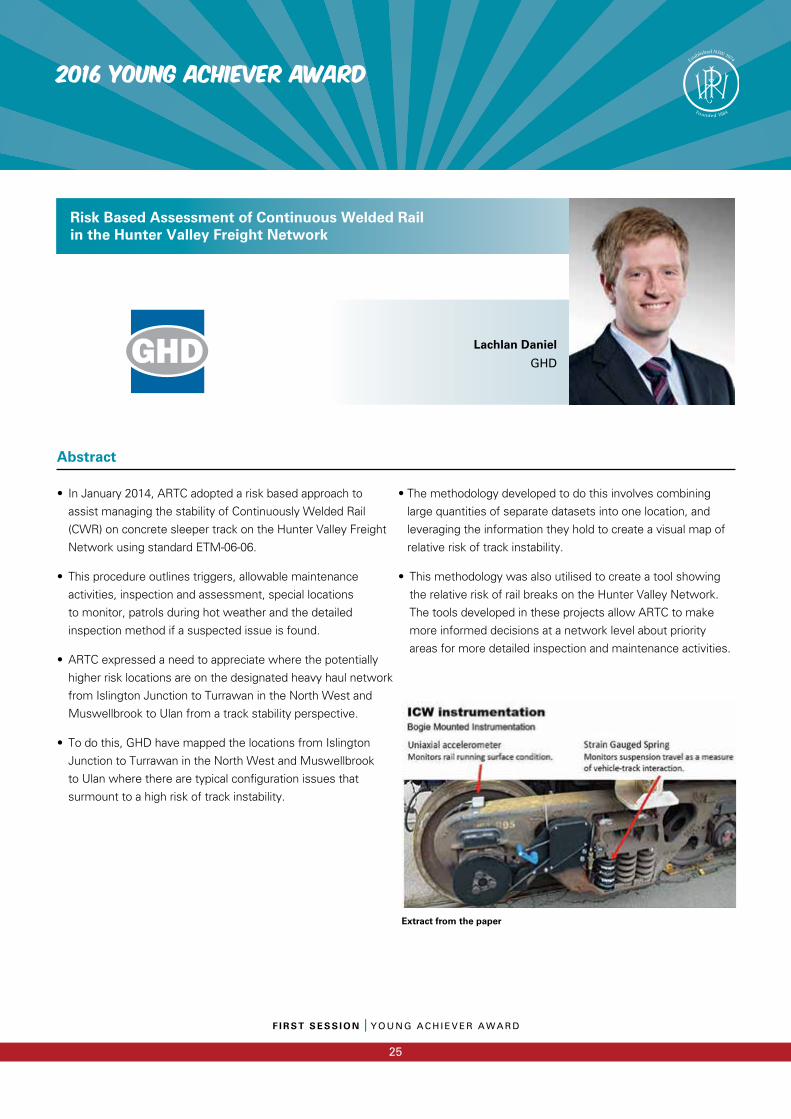
• In January 2014, ARTC adopted a risk based approach to
assist managing the stability of Continuously Welded Rail
(CWR) on concrete sleeper track on the Hunter Valley Freight
Network using standard ETM-06-06.
• This procedure outlines triggers, allowable maintenance
activities, inspection and assessment, special locations
to monitor, patrols during hot weather and the detailed
inspection method if a suspected issue is found.
• ARTC expressed a need to appreciate where the potentially
higher risk locations are on the designated heavy haul network
from Islington Junction to Turrawan in the North West and
Muswellbrook to Ulan from a track stability perspective.
• To do this, GHD have mapped the locations from Islington
Junction to Turrawan in the North West and Muswellbrook
to Ulan where there are typical configuration issues that
surmount to a high risk of track instability.
• The methodology developed to do this involves combining
large quantities of separate datasets into one location, and
leveraging the information they hold to create a visual map of
relative risk of track instability.
• This methodology was also utilised to create a tool showing
the relative risk of rail breaks on the Hunter Valley Network.
The tools developed in these projects allow ARTC to make
more informed decisions at a network level about priority
areas for more detailed inspection and maintenance activities.
Risk Based Assessment of Continuous Welded Railin the Hunter Valley Freight Network
Abstract
Lachlan DanielGHD
Extract from the paper
2016 YOUNG ACHIEVER AWARD
F I R S T S E S S I O N I Y O U N G A C H I E V E R A W A R D
26
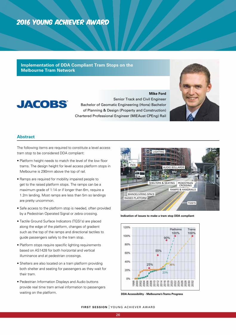
The following items are required to constitute a level access
tram stop to be considered DDA compliant:
• Platform height needs to match the level of the low floor
trams. The design height for level access platform stops in
Melbourne is 290mm above the top of rail.
• Ramps are required for mobility impaired people to
get to the raised platform stops. The ramps can be a
maximum grade of 1:14 or if longer than 6m, require a
1.2m landing. Most ramps are less than 5m so landings
are pretty uncommon.
• Safe access to the platform stop is needed, often provided
by a Pedestrian Operated Signal or zebra crossing.
• Tactile Ground Surface Indicators (TGSI’s) are placed
along the edge of the platform, changes of gradient
such as the top of the ramps and directional tactiles to
guide passengers safely to the tram stop.
• Platform stops require specific lighting requirements
based on AS1428 for both horizontal and vertical
illuminance and at pedestrian crossings.
• Shelters are also located on a tram platform providing
both shelter and seating for passengers as they wait for
their tram.
• Pedestrian Information Displays and Audio buttons
provide real time tram arrival information to passengers
waiting on the platform.
Implementation of DDA Compliant Tram Stops on the Melbourne Tram Network
Abstract
Mike Ford Senior Track and Civil Engineer
Bachelor of Geomatic Engineering (Hons) Bachelor
of Planning & Design (Property and Construction)
Chartered Professional Engineer (MIEAust CPEng) Rail
DDA Accessibility - Melbourne’s Trams Progress
Indication of issues to make a tram stop DDA compliant
LIGHTING
PIDSAUDIO BOLLARDS
PEDESTRIAN CROSSING
RAMPS & HANDRAILS
SHELTERS & SEATING
RAISED PLATFORM
MANOEUVRING SPACE
TGSI’S
Chairman: John Holland Group
Paper 1: Game Day Leadership – Building a Generative
Culture of Leaders
Treaven Martinus, Martinus Rail
Craig Boothroyd, Martinus Rail
Paper 2: Australia’s Engineering Heritage – Life Extension
of the Sydney Central Flying Junction
Debra McLaughlin, Jacobs
Rose Emslie, Jacobs
Lorenz Eberl, Jacobs
Paper 3: New Track Slab Alternative – The Game Changer
for Australia’s Rail Industry
Henrik Vocks, Rhomberg Rail
2016 Alan Barham Maintenance Team Award
SECOND SessionSECOND SessionPWI Annual Convention 2016
Martinus Rail Leadership Academy – Building a Generative Culture of LeadershipCraig Boothroyd, People and Culture Manager
Amanda Reynolds-Smith, Employee Success Facilitator
S E C O N D S E S S I O N I MARTINUS RAIL LEADERSHIP ACADEMY – BUILDING A GENERATIVE CULTURE OF LEADERSHIP
27
Introduction
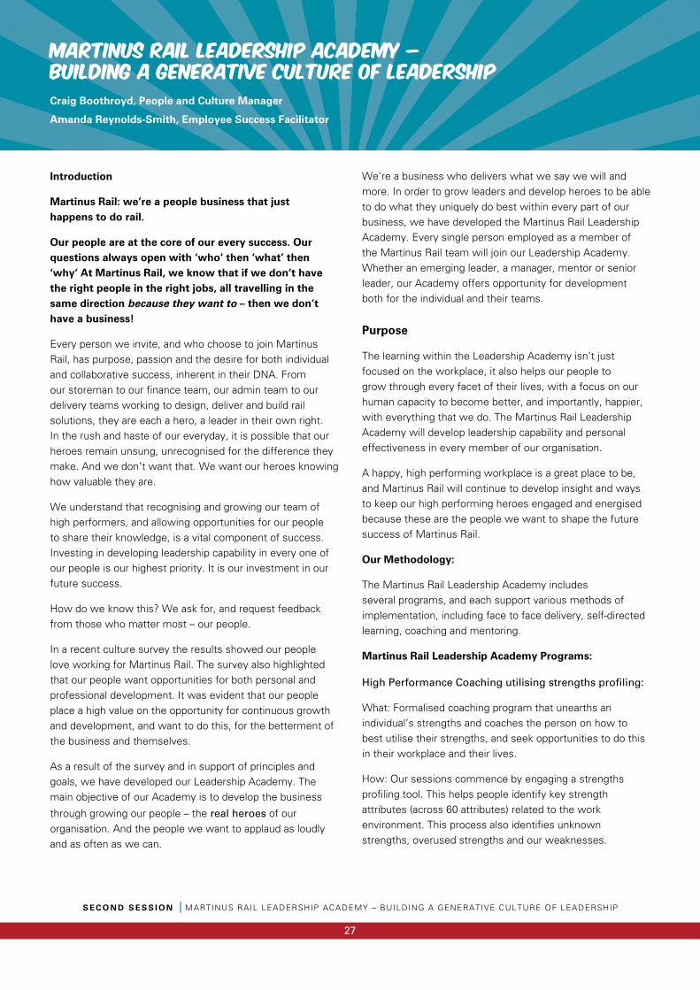
Martinus Rail: we’re a people business that just happens to do rail.
Our people are at the core of our every success. Our questions always open with ‘who’ then ‘what’ then ‘why’ At Martinus Rail, we know that if we don’t have the right people in the right jobs, all travelling in the same direction because they want to – then we don’t have a business!
Every person we invite, and who choose to join Martinus Rail, has purpose, passion and the desire for both individual and collaborative success, inherent in their DNA. From our storeman to our finance team, our admin team to our delivery teams working to design, deliver and build rail solutions, they are each a hero, a leader in their own right. In the rush and haste of our everyday, it is possible that our heroes remain unsung, unrecognised for the difference they make. And we don’t want that. We want our heroes knowing how valuable they are.
We understand that recognising and growing our team of high performers, and allowing opportunities for our people to share their knowledge, is a vital component of success. Investing in developing leadership capability in every one of our people is our highest priority. It is our investment in our future success.
How do we know this? We ask for, and request feedback from those who matter most – our people.
In a recent culture survey the results showed our people love working for Martinus Rail. The survey also highlighted that our people want opportunities for both personal and professional development. It was evident that our people place a high value on the opportunity for continuous growth and development, and want to do this, for the betterment of the business and themselves.
As a result of the survey and in support of principles and goals, we have developed our Leadership Academy. The main objective of our Academy is to develop the business
through growing our people – the real heroes of our organisation. And the people we want to applaud as loudly and as often as we can.
We’re a business who delivers what we say we will and more. In order to grow leaders and develop heroes to be able to do what they uniquely do best within every part of our business, we have developed the Martinus Rail Leadership Academy. Every single person employed as a member of the Martinus Rail team will join our Leadership Academy. Whether an emerging leader, a manager, mentor or senior leader, our Academy offers opportunity for development both for the individual and their teams.
Purpose
The learning within the Leadership Academy isn’t just focused on the workplace, it also helps our people to grow through every facet of their lives, with a focus on our human capacity to become better, and importantly, happier, with everything that we do. The Martinus Rail Leadership Academy will develop leadership capability and personal effectiveness in every member of our organisation.
A happy, high performing workplace is a great place to be, and Martinus Rail will continue to develop insight and ways to keep our high performing heroes engaged and energised because these are the people we want to shape the future success of Martinus Rail.
Our Methodology:
The Martinus Rail Leadership Academy includes several programs, and each support various methods of implementation, including face to face delivery, self-directed learning, coaching and mentoring.
Martinus Rail Leadership Academy Programs:
High Performance Coaching utilising strengths profiling:
What: Formalised coaching program that unearths an individual’s strengths and coaches the person on how to best utilise their strengths, and seek opportunities to do this in their workplace and their lives.
How: Our sessions commence by engaging a strengths profiling tool. This helps people identify key strength attributes (across 60 attributes) related to the work environment. This process also identifies unknown strengths, overused strengths and our weaknesses.
S E C O N D S E S S I O N I MARTINUS RAIL LEADERSHIP ACADEMY – BUILDING A GENERATIVE CULTURE OF LEADERSHIP
28
Martinus Rail Leadership Academy – Building a Generative Culture of Leadership
We then work with our people across factors such as aligning their strengths with work tasks and adapting or reducing tasks that de-energise them.
Why: Martinus Rail is a strengths based organisation. We know that working in alignment with our strengths gives us energy. We want our people to know and understand their strengths, and for our business to know these too, so we can help our people to ensure we have a team of high performers, who are energised and doing what they love – because they’re working to their strengths!
Emerging Leader Program (ELP):
What: Strategies for growing leadership strengths in our people, particularly those working in individual roles who’ve been identified for potential in leading teams
How: Engaging Emotional Intelligence (EQ) and Strengths Profiling tools, utilising that knowledge as well as tools relevant to their individual roles to build a platform for learning leaders to safely develop their capability. This program aligns closely with the person’s individual performance development plan
Why: Great leaders at every level of our organisation help us on our journey to greatness
Leading Team Success Program (LTS):
What: A program with competencies around behaviorand leadership need to enable existing leaders to be more successful.
How: A series of 2 day workshops, followed by individual coaching over the subsequent 6 month period. This program aligns closely with the person’s individual performance development plan
Why: Great leaders grow great leaders and nurture high performance teams
Senior Leadership Development Program (SLT):
What: For managers in senior roles (levels of responsibility). This program looks at the ‘what,’ ‘how’ and ‘why’ of leading an organisation, and the impact that senior leaders have on organisational culture
How: Development days throughout the year that will involve various elements such as measuring the SLT’s influence on their teams/culture via tools such as 360 reviews.
To establish, manage and monitor key leadership themes within the company, to develop, manage and monitor the company’s standards across all levels of the organisation. An executive coaching program is available to the SLT. This is delivered through a combination of internal and external coaching professionals.
Why: Our Senior Leaders set the tone, the state of play and the standards – their skills are valuable and are worth growing and sharing – they are integral in laying the steps of our path to greatness
Game Day Leadership (GDL):
What: a philosophy grown from sporting teams’ ‘game day’ expectations. Game Day Leaders make it ‘how’ we will achieve our ‘win,’ our success. Game Day Leaders set the tone and the mindset of the entire team. The Game Day Leadership program is primarily used for our possession and project work.
How: Through monitoring our 3 C’s - clarity, climate and competence - via a set of criteria measuring
EQ, values, basic principles (understanding the critical point of the job), standard/expectations (both behavioural and technical) and continual review of the 3C’s we deliver outstanding results
Why: It is vital a leader knows and understands their team, and is aware of the strengths and challenges of the individuals and the group. A Game Day Leader knows the core values and drivers of the team. They know what each person needs to perform as their best so that the entire team achieves success.
We understand that recognising and
growing our team of high performers,
and allowing opportunities for our
people to share their knowledge, is
a vital component of success.
Martinus Rail Leadership Academy – Building a Generative Culture of Leadership
S E C O N D S E S S I O N I MARTINUS RAIL LEADERSHIP ACADEMY – BUILDING A GENERATIVE CULTURE OF LEADERSHIP
29
Martinus Rail Leadership Support Tools:
Performance Success Plan
This is a comprehensive document that includes:
(a) Role Profile – an outline of all competencies, tasks and behaviours expected of someone performing in that role. It encompasses the (a) being – behavioural, leadership expectations and (b) doing – tasks, actions, qualifications and expertise
(b) How to be a high performer – the doing and being elements of a high performer (a hero)
(c) Success Plan - goals, development needs/opportunities and other elements to ensure the person realises theirfull potential
Team Building
The resources, including both people and tools, within the Leadership Academy will coordinate and assist to help in team building days for different departments and the overall organisation. Team building days will have a variety of focus points. They could be to build competencies or behaviours as identified in leadership development workshops or designed to simply build team work. Events may include survivor style activities, problem solving or sporting activities and will always be designed with objectives/outcomes in mind. These days occur intermittently throughout the year with at least one day per team, and an overall company day.
Leadership Website
Martinus Rail is in the process of finalising a leadership development website for our team. The website will offer an abundance of leadership development material specific to Martinus Rail, that supports established leadership competencies, behaviours and technical training.
Leadership bleets
Weekly ‘bleets’ will be posted on the website which will be short and sharp leadership quotes, articles or links to other relevant material.
Leadership articles
Monthly leadership articles are shared with the organisation, illustrating established leadership competencies and behaviours for Martinus Rail.
Leadership podcasts
Under development, we have an ever increasing series of interviews conducted with both internal and external professionals focusing in leadership insights, ideas, programs and methodologies.
Technical Training Material
All technical training and job specific detail is available via our intranet.

The UNSUNG Heroes
The UNSUNG Heroes
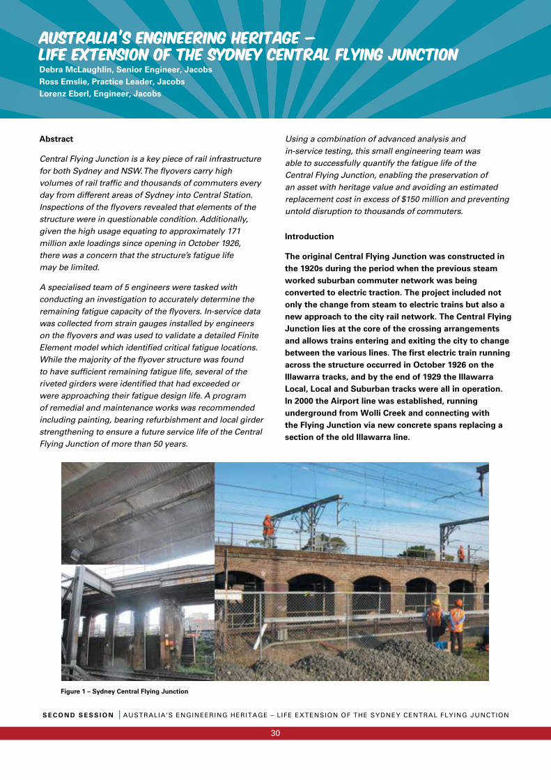
AUSTRALIA’S ENGINEERING HERITAGE – LIFE EXTENSION OF THE SYDNEY CENTRAL FLYING JUNCTIONDebra McLaughlin, Senior Engineer, JacobsRoss Emslie, Practice Leader, JacobsLorenz Eberl, Engineer, Jacobs
S E C O N D S E S S I O N I AUSTRALIA’S ENGINEERING HERITAGE – LIFE EXTENSION OF THE SYDNEY CENTRAL FLYING JUNCTION
30
Abstract
Central Flying Junction is a key piece of rail infrastructure for both Sydney and NSW. The fl yovers carry high volumes of rail traffi c and thousands of commuters every day from different areas of Sydney into Central Station. Inspections of the fl yovers revealed that elements of the structure were in questionable condition. Additionally, given the high usage equating to approximately 171 million axle loadings since opening in October 1926, there was a concern that the structure’s fatigue life may be limited.
A specialised team of 5 engineers were tasked with conducting an investigation to accurately determine the remaining fatigue capacity of the fl yovers. In-service data was collected from strain gauges installed by engineers on the fl yovers and was used to validate a detailed Finite Element model which identifi ed critical fatigue locations. While the majority of the fl yover structure was found to have suffi cient remaining fatigue life, several of the riveted girders were identifi ed that had exceeded or were approaching their fatigue design life. A program of remedial and maintenance works was recommended including painting, bearing refurbishment and local girder strengthening to ensure a future service life of the Central Flying Junction of more than 50 years.
Using a combination of advanced analysis and in-service testing, this small engineering team was able to successfully quantify the fatigue life of the Central Flying Junction, enabling the preservation of an asset with heritage value and avoiding an estimated replacement cost in excess of $150 million and preventing untold disruption to thousands of commuters.
Introduction
The original Central Flying Junction was constructed in the 1920s during the period when the previous steam worked suburban commuter network was being converted to electric traction. The project included not only the change from steam to electric trains but also a new approach to the city rail network. The Central Flying Junction lies at the core of the crossing arrangements and allows trains entering and exiting the city to change between the various lines. The first electric train running across the structure occurred in October 1926 on the Illawarra tracks, and by the end of 1929 the Illawarra Local, Local and Suburban tracks were all in operation. In 2000 the Airport line was established, running underground from Wolli Creek and connecting with the Flying Junction via new concrete spans replacing a section of the old Illawarra line.
Figure 1 – Sydney Central Flying Junction
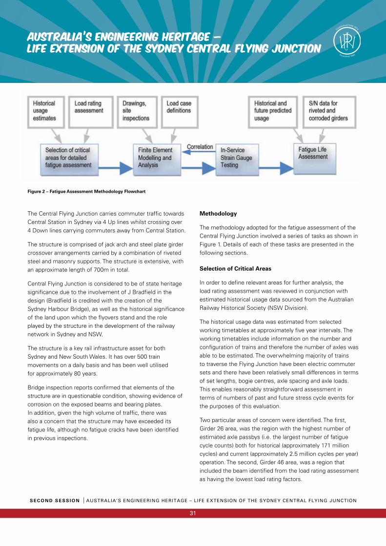
31
The Central Flying Junction carries commuter traffi c towards Central Station in Sydney via 4 Up lines whilst crossing over 4 Down lines carrying commuters away from Central Station.
The structure is comprised of jack arch and steel plate girder crossover arrangements carried by a combination of riveted steel and masonry supports. The structure is extensive, with an approximate length of 700m in total.
Central Flying Junction is considered to be of state heritage signifi cance due to the involvement of J Bradfi eld in the design (Bradfi eld is credited with the creation of the Sydney Harbour Bridge), as well as the historical signifi cance of the land upon which the fl yovers stand and the role played by the structure in the development of the railway network in Sydney and NSW.
The structure is a key rail infrastructure asset for both Sydney and New South Wales. It has over 500 train movements on a daily basis and has been well utilisedfor approximately 80 years.
Bridge inspection reports confi rmed that elements of the structure are in questionable condition, showing evidence of corrosion on the exposed beams and bearing plates. In addition, given the high volume of traffi c, there wasalso a concern that the structure may have exceeded its fatigue life, although no fatigue cracks have been identifi ed in previous inspections.
Methodology
The methodology adopted for the fatigue assessment of the Central Flying Junction involved a series of tasks as shown in Figure 1. Details of each of these tasks are presented in the following sections.
Selection of Critical Areas
In order to defi ne relevant areas for further analysis, the load rating assessment was reviewed in conjunction with estimated historical usage data sourced from the Australian Railway Historical Society (NSW Division).
The historical usage data was estimated from selected working timetables at approximately fi ve year intervals. The working timetables include information on the number and confi guration of trains and therefore the number of axles was able to be estimated. The overwhelming majority of trains to traverse the Flying Junction have been electric commuter sets and there have been relatively small differences in terms of set lengths, bogie centres, axle spacing and axle loads. This enables reasonably straightforward assessment in terms of numbers of past and future stress cycle events for the purposes of this evaluation.
Two particular areas of concern were identifi ed. The fi rst, Girder 26 area, was the region with the highest number of estimated axle passbys (i.e. the largest number of fatigue cycle counts) both for historical (approximately 171 million cycles) and current (approximately 2.5 million cycles per year) operation. The second, Girder 46 area, was a region that included the beam identifi ed from the load rating assessment as having the lowest load rating factors.
AUSTRALIA’S ENGINEERING HERITAGE – LIFE EXTENSION OF THE SYDNEY CENTRAL FLYING JUNCTION
S E C O N D S E S S I O N I AUSTRALIA’S ENGINEERING HERITAGE – LIFE EXTENSION OF THE SYDNEY CENTRAL FLYING JUNCTION
Figure 2 – Fatigue Assessment Methodology Flowchart
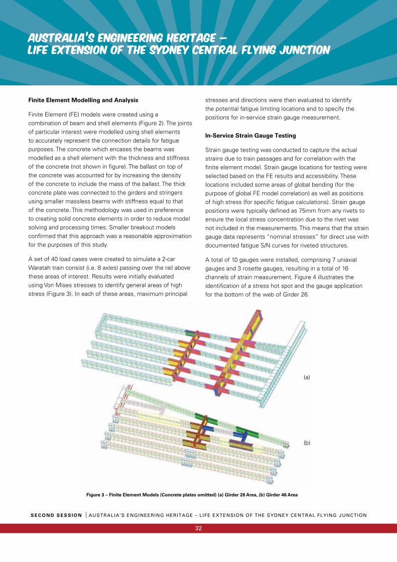
AUSTRALIA’S ENGINEERING HERITAGE – LIFE EXTENSION OF THE SYDNEY CENTRAL FLYING JUNCTION
S E C O N D S E S S I O N I AUSTRALIA’S ENGINEERING HERITAGE – LIFE EXTENSION OF THE SYDNEY CENTRAL FLYING JUNCTION
32
Finite Element Modelling and Analysis
Finite Element (FE) models were created using a combination of beam and shell elements (Figure 2). The joints of particular interest were modelled using shell elements to accurately represent the connection details for fatigue purposes. The concrete which encases the beams was modelled as a shell element with the thickness and stiffness of the concrete (not shown in fi gure). The ballast on top of the concrete was accounted for by increasing the density of the concrete to include the mass of the ballast. The thick concrete plate was connected to the girders and stringers using smaller massless beams with stiffness equal to that of the concrete. This methodology was used in preference to creating solid concrete elements in order to reduce model solving and processing times. Smaller breakout models confi rmed that this approach was a reasonable approximation for the purposes of this study.
A set of 40 load cases were created to simulate a 2-car Waratah train consist (i.e. 8 axles) passing over the rail above these areas of interest. Results were initially evaluated using Von Mises stresses to identify general areas of high stress (Figure 3). In each of these areas, maximum principal
stresses and directions were then evaluated to identify the potential fatigue limiting locations and to specify the positions for in-service strain gauge measurement.
In-Service Strain Gauge Testing
Strain gauge testing was conducted to capture the actual strains due to train passages and for correlation with the fi nite element model. Strain gauge locations for testing were selected based on the FE results and accessibility. These locations included some areas of global bending (for the purpose of global FE model correlation) as well as positions of high stress (for specifi c fatigue calculations). Strain gauge positions were typically defi ned as 75mm from any rivets to ensure the local stress concentration due to the rivet was not included in the measurements. This means that the strain gauge data represents “nominal stresses” for direct use with documented fatigue S/N curves for riveted structures.
A total of 10 gauges were installed, comprising 7 uniaxial gauges and 3 rosette gauges, resulting in a total of 16 channels of strain measurement. Figure 4 illustrates the identifi cation of a stress hot spot and the gauge application for the bottom of the web of Girder 26.
Figure 3 – Finite Element Models (Concrete plates omitted) (a) Girder 26 Area, (b) Girder 46 Area
(a)
(b)
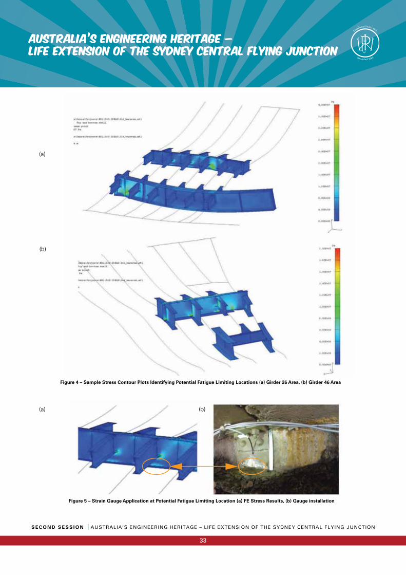
S E C O N D S E S S I O N I AUSTRALIA’S ENGINEERING HERITAGE – LIFE EXTENSION OF THE SYDNEY CENTRAL FLYING JUNCTION
33
AUSTRALIA’S ENGINEERING HERITAGE – LIFE EXTENSION OF THE SYDNEY CENTRAL FLYING JUNCTION
(a)
(a)
(b)
Figure 4 – Sample Stress Contour Plots Identifying Potential Fatigue Limiting Locations (a) Girder 26 Area, (b) Girder 46 Area
Figure 5 – Strain Gauge Application at Potential Fatigue Limiting Location (a) FE Stress Results, (b) Gauge installation
(b)

AUSTRALIA’S ENGINEERING HERITAGE – LIFE EXTENSION OF THE SYDNEY CENTRAL FLYING JUNCTION
S E C O N D S E S S I O N I AUSTRALIA’S ENGINEERING HERITAGE – LIFE EXTENSION OF THE SYDNEY CENTRAL FLYING JUNCTION
34
The strain data was sampled at 200 Hz with a 30 Hz low pass fi lter applied using a Somat eDaq fi eld computer. Time history and rainfl ow statistical data was recorded for all channels between 14th and 24th July 2013. During this time a total of 2075 trains traversed the Girder 26 Area and 1711 trains traversed the Girder 46 Area.
Figure 5 shows the typical time history for one gauge over a one-day period and for the traverse of a single 8-car train. Individual bogies are easily identifi ed, while individual axles are not able to be distinguished. The few higher magnitude events in Figure 5 (a) are due to trains that pass on the Local to Illawarra Local Crossover (the closest line to this strain gauge location), while the smaller magnitude events indicate more frequent trains on the Up Local line (slightly further from this strain gauge location). Similar train passbys are consistently of similar magnitude over a long period, with the relatively small variations likely due to differences in car weight and passenger loading.
Finite Element Correlation
For correlation purposes the test results for a lowly loaded or empty Waratah 8-car consist have been compared with the FE results for a simulated empty Waratah 2-car consist. Uniaxial strains were converted to stress assuming a uniaxial stress fi eld (� = E�). The alternating stress range (rather than peak stress) was used for comparison, as this is the critical input for fatigue calculations. In order to improve correlation two modifi cations were made to the original FE model:
• In the area directly adjacent to Girder 26 the shell elements representing the concrete were replaced with solid elements in order to better predict stresses on the web under the concrete.
• The thickness of the concrete plate was reduced in both models.
Figure 6 – Sample Strain Time History for (a) one day, (b) an 8-car train
(a)
(b)
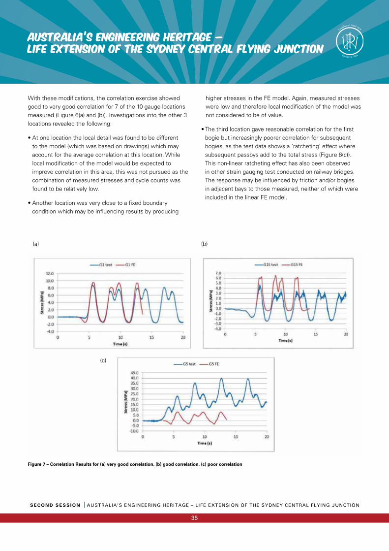
S E C O N D S E S S I O N I AUSTRALIA’S ENGINEERING HERITAGE – LIFE EXTENSION OF THE SYDNEY CENTRAL FLYING JUNCTION
35
AUSTRALIA’S ENGINEERING HERITAGE – LIFE EXTENSION OF THE SYDNEY CENTRAL FLYING JUNCTION
With these modifi cations, the correlation exercise showed good to very good correlation for 7 of the 10 gauge locations measured (Figure 6(a) and (b)). Investigations into the other 3 locations revealed the following:
• At one location the local detail was found to be different to the model (which was based on drawings) which may account for the average correlation at this location. While local modifi cation of the model would be expected to improve correlation in this area, this was not pursued as the combination of measured stresses and cycle counts was found to be relatively low.
• Another location was very close to a fi xed boundary condition which may be infl uencing results by producing
higher stresses in the FE model. Again, measured stresses were low and therefore local modifi cation of the model was not considered to be of value.
• The third location gave reasonable correlation for the fi rst bogie but increasingly poorer correlation for subsequent bogies, as the test data shows a ‘ratcheting’ effect where subsequent passbys add to the total stress (Figure 6(c)). This non-linear ratcheting effect has also been observed in other strain gauging test conducted on railway bridges. The response may be infl uenced by friction and/or bogies in adjacent bays to those measured, neither of which were included in the linear FE model.
Figure 7 – Correlation Results for (a) very good correlation, (b) good correlation, (c) poor correlation
(b)(a)
(c)
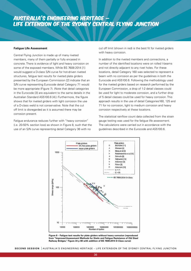
AUSTRALIA’S ENGINEERING HERITAGE – LIFE EXTENSION OF THE SYDNEY CENTRAL FLYING JUNCTION
S E C O N D S E S S I O N I AUSTRALIA’S ENGINEERING HERITAGE – LIFE EXTENSION OF THE SYDNEY CENTRAL FLYING JUNCTION
36
Fatigue Life Assessment
Central Flying Junction is made up of many riveted members, many of them partially or fully encased in concrete. There is evidence of light and heavy corrosion on some of the exposed members. While BS 7608:2014 [1] would suggest a D-class S/N curve for hot-driven riveted structures, fatigue test results for riveted plate girders presented by the European Commission [2] indicate that an S/N curve representing Eurocode detail Category 71 would be more appropriate (Figure 7). (Note that detail categories in the Eurocode [3] are equivalent to the same details in the Australian Standard AS5100.6 [4].) Furthermore, the fi gure shows that for riveted girders with light corrosion the use of a D-class weld is not conservative. Note that the cut off limit is disregarded as it is assumed there may be corrosion present.
Fatigue endurance reduces further with “heavy corrosion” (i.e. 20-50% section loss) as shown in Figure 8, such that the use of an S/N curve representing detail Category 36 with no
cut off limit (shown in red) is the best fi t for riveted girders with heavy corrosion.
In addition to the riveted members and connections, a number of the identifi ed locations were on rolled I-beams and not directly adjacent to any rivet holes. For these locations, detail Category 160 was selected to represent a beam with no corrosion as per the guidelines in both the Eurocode and AS5100.6. Following the methodology used for the riveted girders based on research performed by the European Commission, a drop of 1-2 detail classes could be used for light to moderate corrosion, and a further drop of 5 detail classes could be used for heavy corrosion. This approach results in the use of detail Categories160, 125 and 71 for no corrosion, light to medium corrosion and heavy corrosion respectively at these locations.
The statistical rainfl ow count data collected from the strain gauge testing was used for the fatigue life assessment. The calculations were carried out in accordance with the guidelines described in the Eurocode and AS5100.6.
Figure 8 – Fatigue test results for plate girders without heavy corrosion (reproduced from “Improved Assessment Methods for Static and Fatigue Resistance of Old Steel Railway Bridges,” Figure 34 p 88 with addition of BS 7608:2014 D-Class curve)
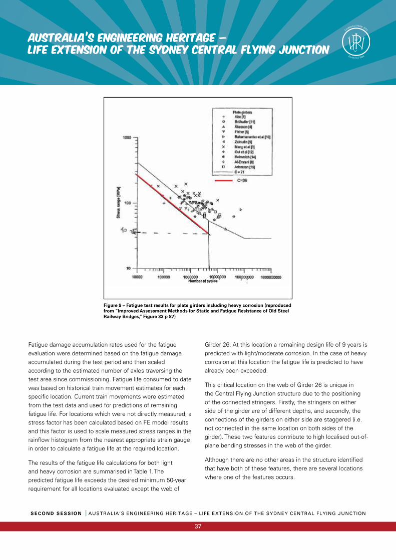
S E C O N D S E S S I O N I AUSTRALIA’S ENGINEERING HERITAGE – LIFE EXTENSION OF THE SYDNEY CENTRAL FLYING JUNCTION
37
AUSTRALIA’S ENGINEERING HERITAGE – LIFE EXTENSION OF THE SYDNEY CENTRAL FLYING JUNCTION
Fatigue damage accumulation rates used for the fatigue evaluation were determined based on the fatigue damage accumulated during the test period and then scaled according to the estimated number of axles traversing the test area since commissioning. Fatigue life consumed to date was based on historical train movement estimates for each specifi c location. Current train movements were estimated from the test data and used for predictions of remaining fatigue life. For locations which were not directly measured, a stress factor has been calculated based on FE model results and this factor is used to scale measured stress ranges in the rainfl ow histogram from the nearest appropriate strain gauge in order to calculate a fatigue life at the required location.
The results of the fatigue life calculations for both light and heavy corrosion are summarised in Table 1. The predicted fatigue life exceeds the desired minimum 50-year requirement for all locations evaluated except the web of
Girder 26. At this location a remaining design life of 9 years is predicted with light/moderate corrosion. In the case of heavy corrosion at this location the fatigue life is predicted to have already been exceeded.
This critical location on the web of Girder 26 is unique in the Central Flying Junction structure due to the positioning of the connected stringers. Firstly, the stringers on either side of the girder are of different depths, and secondly, the connections of the girders on either side are staggered (i.e. not connected in the same location on both sides of the girder). These two features contribute to high localised out-of-plane bending stresses in the web of the girder.
Although there are no other areas in the structure identifi ed that have both of these features, there are several locations where one of the features occurs.
Figure 9 – Fatigue test results for plate girders including heavy corrosion (reproduced from “Improved Assessment Methods for Static and Fatigue Resistance of Old Steel Railway Bridges,” Figure 33 p 87)
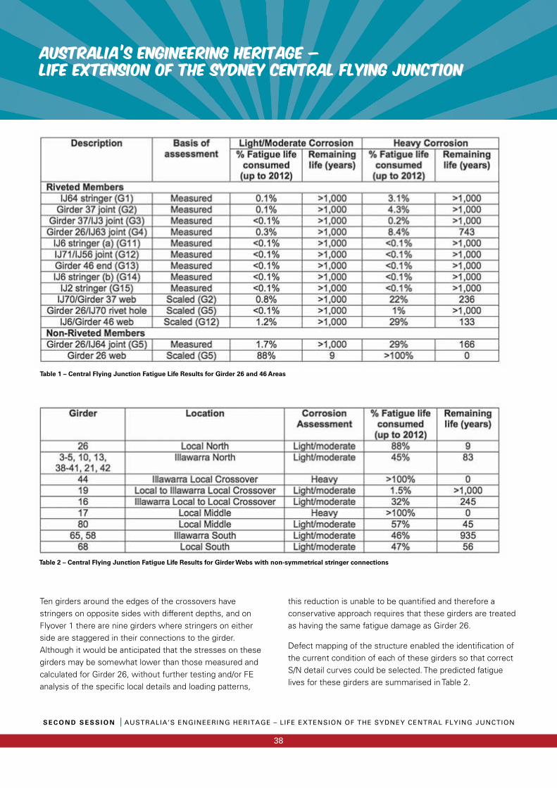
AUSTRALIA’S ENGINEERING HERITAGE – LIFE EXTENSION OF THE SYDNEY CENTRAL FLYING JUNCTION
S E C O N D S E S S I O N I AUSTRALIA’S ENGINEERING HERITAGE – LIFE EXTENSION OF THE SYDNEY CENTRAL FLYING JUNCTION
38
Ten girders around the edges of the crossovers have stringers on opposite sides with different depths, and on Flyover 1 there are nine girders where stringers on either side are staggered in their connections to the girder. Although it would be anticipated that the stresses on these girders may be somewhat lower than those measured and calculated for Girder 26, without further testing and/or FE analysis of the specifi c local details and loading patterns,
this reduction is unable to be quantifi ed and therefore a conservative approach requires that these girders are treated as having the same fatigue damage as Girder 26.
Defect mapping of the structure enabled the identifi cation of the current condition of each of these girders so that correct S/N detail curves could be selected. The predicted fatigue lives for these girders are summarised in Table 2.
Table 1 – Central Flying Junction Fatigue Life Results for Girder 26 and 46 Areas
Table 2 – Central Flying Junction Fatigue Life Results for Girder Webs with non-symmetrical stringer connections
S E C O N D S E S S I O N I AUSTRALIA’S ENGINEERING HERITAGE – LIFE EXTENSION OF THE SYDNEY CENTRAL FLYING JUNCTION
39
AUSTRALIA’S ENGINEERING HERITAGE – LIFE EXTENSION OF THE SYDNEY CENTRAL FLYING JUNCTION
Four girders were identifi ed as having low (less than 50 years) or may have exceeded their fatigue lives. It is noted, however, that the assumptions and methodology used for these locations necessarily includes some level of conservatism due to the fact that hot-spot stresses have not been directly measured. Furthermore, many of these hot-spots are encased in concrete and therefore are not easily accessible for measurement or inspection. A further investigation (FE analysis and/or test program) into those areas that were not directly tested/modelled in this evaluation may quantify this uncertainty and has the potential to increase predicted fatigue lives.
The level of corrosion is a signifi cant factor, with up to 16 girders indicated to have low or potentially non-existent fatigue lives with heavy corrosion. While inspections indicate that most locations currently experience only light corrosion, the criticality of this aspect highlights the importance of protective coatings on all exposed steel members.
In order to mitigate the risk of fatigue cracking in the structure, a program of maintenance, inspections and localised repairs were recommended.
Conclusions
A combination of detailed fi nite element analysis and targeted strain gauge measurements was able to accurately quantify the remaining fatigue life of Central Flying Junction. Overall, the structure was indicated to have a long fatigue life even with mild to heavy corrosion present (up to 20% section loss). Stress cycles were generally low (<50 MPa), however fi nite fatigue lives are indicated in a number of locations due to the presence of corrosion and the large number of cycle counts in both past (>100 million) and future (up to 2.5 million per year) operation.
Reaching the fatigue life of the structure would necessarily require either signifi cant repairs and modifi cation or replacement to be considered. A feasibility study conducted by Sydney Trains reported a replacement cost of approximately $150 million for a single fl yover, suggesting potential costs of $600 million for the whole structure.
While inspections indicate that most
locations currently experience only light
corrosion, the criticality of this aspect
highlights the importance of protective
coatings on all exposed steel members.
Furthermore, the disruption costs and negative publicity associated with the temporary removal of services wouldbe considerable. The detailed fatigue life evaluation combined with a load rating assessment and program of scheduled maintenance services has allowed for the service life of the Central Flying Junction to be safely extended by a minimum 50 years.
References
[1] BS 7608:2014 Guide to fatigue design and assessment of steel products
[2] Cremona, C., Patron, A., Johansson, B. et al (2007). Improved Assessment Methods for Static and Fatigue Resistance of Old Steel Railway Bridges, Deliverable D4.6, European Commission with the Sixth Framework Programme (2002-2006).
[3] EN 1993-1-9:2005 Eurocode 3: Design of steel structures – Part 1-9: Fatigue
[4] AS5100.6–2004 Bridge design – Part 6: Steel and composite construction
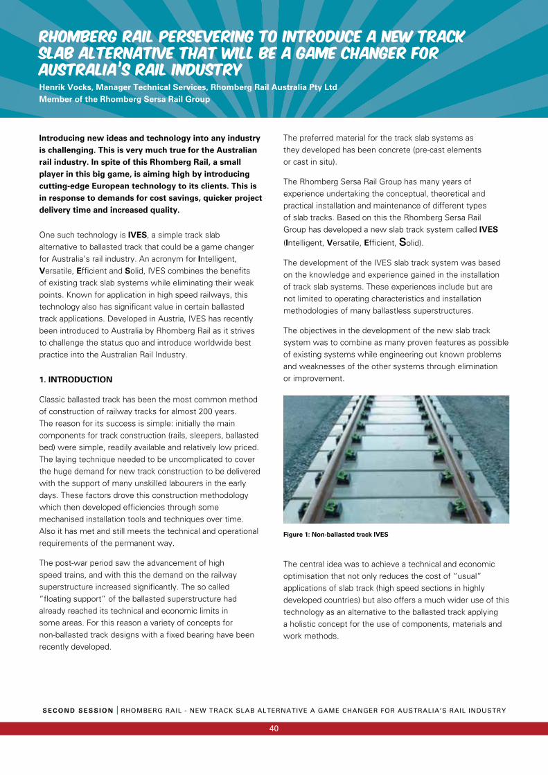
RHOMBERG RAIL PERSEVERING TO INTRODUCE A NEW TRACK SLAB ALTERNATIVE THAT WILL BE A GAME CHANGER FOR AUSTRALIA’S RAIL INDUSTRYHenrik Vocks, Manager Technical Services, Rhomberg Rail Australia Pty Ltd Member of the Rhomberg Sersa Rail Group
S E C O N D S E S S I O N I RHOMBERG RAIL - NEW TRACK SLAB ALTERNATIVE A GAME CHANGER FOR AUSTRALIA’S RAIL INDUSTRY
40
Introducing new ideas and technology into any industry is challenging. This is very much true for the Australian rail industry. In spite of this Rhomberg Rail, a small player in this big game, is aiming high by introducing cutting-edge European technology to its clients. This is in response to demands for cost savings, quicker project delivery time and increased quality.
One such technology is IVES, a simple track slab alternative to ballasted track that could be a game changer for Australia’s rail industry. An acronym for Intelligent, Versatile, Efficient and Solid, IVES combines the benefits of existing track slab systems while eliminating their weak points. Known for application in high speed railways, this technology also has significant value in certain ballasted track applications. Developed in Austria, IVES has recently been introduced to Australia by Rhomberg Rail as it strives to challenge the status quo and introduce worldwide best practice into the Australian Rail Industry.
1. INTRODUCTION
Classic ballasted track has been the most common method of construction of railway tracks for almost 200 years. The reason for its success is simple: initially the main components for track construction (rails, sleepers, ballasted bed) were simple, readily available and relatively low priced. The laying technique needed to be uncomplicated to cover the huge demand for new track construction to be delivered with the support of many unskilled labourers in the early days. These factors drove this construction methodology which then developed efficiencies through some mechanised installation tools and techniques over time. Also it has met and still meets the technical and operational requirements of the permanent way.
The post-war period saw the advancement of high speed trains, and with this the demand on the railway superstructure increased significantly. The so called“floating support” of the ballasted superstructure had already reached its technical and economic limits in some areas. For this reason a variety of concepts for non-ballasted track designs with a fixed bearing have been recently developed.
The preferred material for the track slab systems as they developed has been concrete (pre-cast elements or cast in situ).
The Rhomberg Sersa Rail Group has many years of experience undertaking the conceptual, theoretical and practical installation and maintenance of different types of slab tracks. Based on this the Rhomberg Sersa Rail Group has developed a new slab track system called IVES
(Intelligent, Versatile, Efficient, Solid).
The development of the IVES slab track system was based on the knowledge and experience gained in the installation of track slab systems. These experiences include but are not limited to operating characteristics and installation methodologies of many ballastless superstructures.
The objectives in the development of the new slab track system was to combine as many proven features as possible of existing systems while engineering out known problems and weaknesses of the other systems through elimination or improvement.
Figure 1: Non-ballasted track IVES
The central idea was to achieve a technical and economic optimisation that not only reduces the cost of “usual” applications of slab track (high speed sections in highly developed countries) but also offers a much wider use of this technology as an alternative to the ballasted track applying a holistic concept for the use of components, materials and work methods.
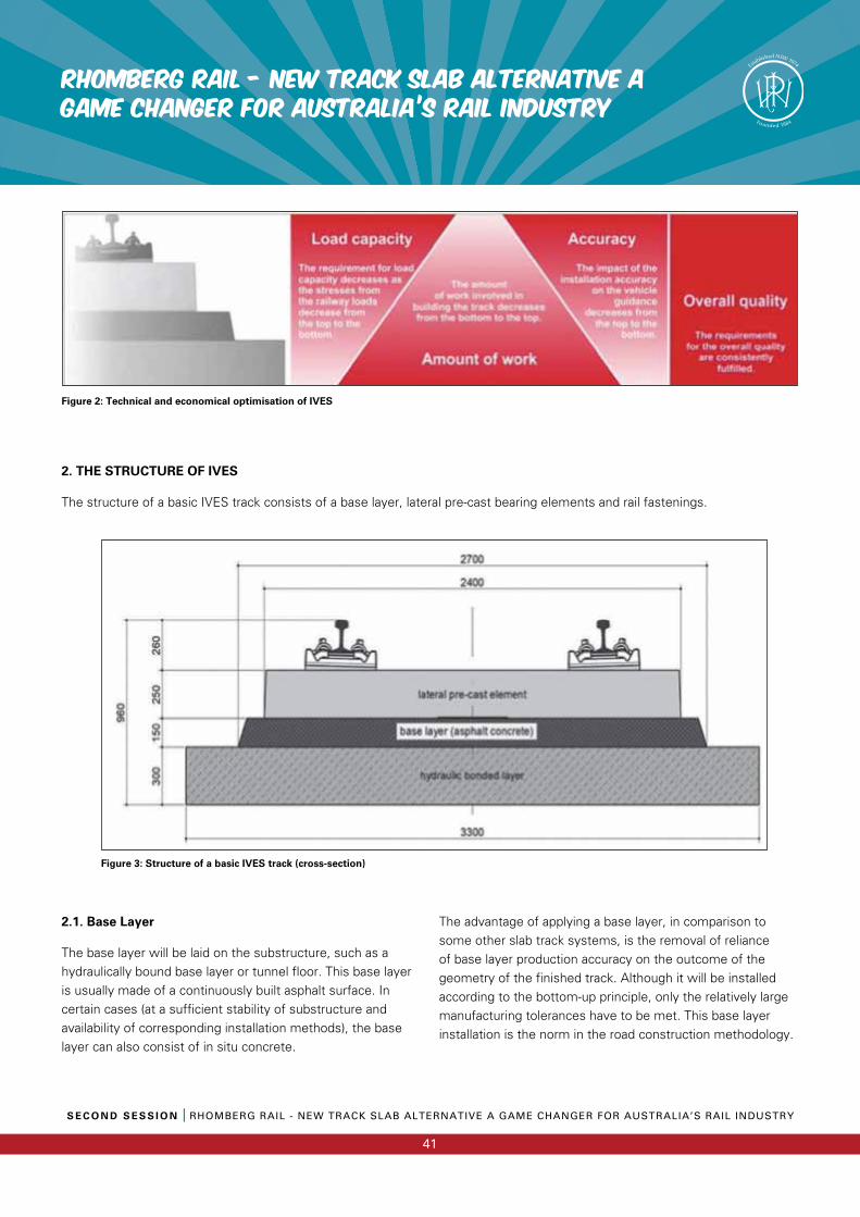
S E C O N D S E S S I O N I RHOMBERG RAIL - NEW TRACK SLAB ALTERNATIVE A GAME CHANGER FOR AUSTRALIA’S RAIL INDUSTRY
41
RHOMBERG RAIL - NEW TRACK SLAB ALTERNATIVE a GAME CHANGER FOR AUSTRALIA’S RAIL INDUSTRY
2. THE STRUCTURE OF IVES
The structure of a basic IVES track consists of a base layer, lateral pre-cast bearing elements and rail fastenings.
Figure 2: Technical and economical optimisation of IVES
Figure 3: Structure of a basic IVES track (cross-section)
2.1. Base Layer
The base layer will be laid on the substructure, such as a hydraulically bound base layer or tunnel floor. This base layer is usually made of a continuously built asphalt surface. In certain cases (at a sufficient stability of substructure and availability of corresponding installation methods), the base layer can also consist of in situ concrete.
The advantage of applying a base layer, in comparison to some other slab track systems, is the removal of reliance of base layer production accuracy on the outcome of the geometry of the finished track. Although it will be installed according to the bottom-up principle, only the relatively large manufacturing tolerances have to be met. This base layer installation is the norm in the road construction methodology.
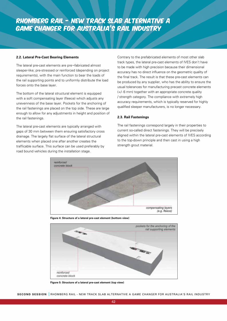
RHOMBERG RAIL - NEW TRACK SLAB ALTERNATIVE a GAME CHANGER FOR AUSTRALIA’S RAIL INDUSTRY
S E C O N D S E S S I O N I RHOMBERG RAIL - NEW TRACK SLAB ALTERNATIVE A GAME CHANGER FOR AUSTRALIA’S RAIL INDUSTRY
42
2.2. Lateral Pre-Cast Bearing Elements
The lateral pre-cast elements are pre¬fabricated almost sleeper-like; pre-stressed or reinforced (depending on project requirements), with the main function to bear the loads of the rail supporting points and to uniformly distribute the load forces onto the base layer.
The bottom of the lateral structural element is equipped with a soft compensating layer (fleece) which adjusts any unevenness of the base layer. Pockets for the anchoring of the rail fastenings are placed on the top side. These are large enough to allow for any adjustments in height and position of the rail fastenings.
The lateral pre-cast elements are typically arranged with gaps of 30 mm between them ensuring satisfactory cross drainage. The largely flat surface of the lateral structural elements when placed one after another creates the trafficable surface. This surface can be used preferably by road bound vehicles during the installation stage.
Contrary to the prefabricated elements of most other slab track types, the lateral pre-cast elements of IVES don’t have to be made with high precision because their dimensional accuracy has no direct influence on the geometric quality of the final track. The result is that these pre-cast elements can be produced by any supplier, who has the ability to ensure the usual tolerances for manufacturing precast concrete elements (+/- 6 mm) together with an appropriate concrete quality / strength category. The compliance with extremely high accuracy requirements, which is typically reserved for highly qualified sleeper manufacturers, is no longer necessary.
2.3. Rail Fastenings
The rail fastenings correspond largely in their properties to current so-called direct fastenings. They will be precisely aligned within the lateral pre-cast elements of IVES according to the top-down principle and then cast in using a high strength grout material.
Figure 4: Structure of a lateral pre-cast element (bottom view)
Figure 5: Structure of a lateral pre-cast element (top view)
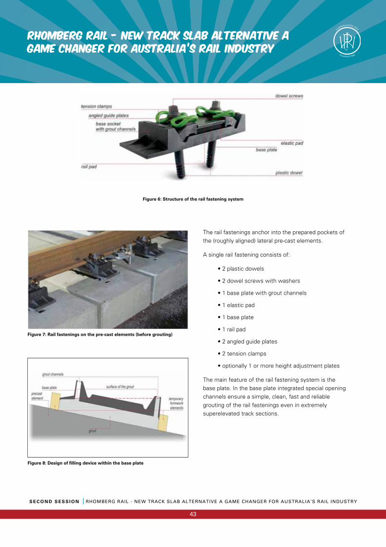
S E C O N D S E S S I O N I RHOMBERG RAIL - NEW TRACK SLAB ALTERNATIVE A GAME CHANGER FOR AUSTRALIA’S RAIL INDUSTRY
43
RHOMBERG RAIL - NEW TRACK SLAB ALTERNATIVE a GAME CHANGER FOR AUSTRALIA’S RAIL INDUSTRY
The rail fastenings anchor into the prepared pockets of the (roughly aligned) lateral pre-cast elements.
A single rail fastening consists of:
• 2 plastic dowels
• 2 dowel screws with washers
• 1 base plate with grout channels
• 1 elastic pad
• 1 base plate
• 1 rail pad
• 2 angled guide plates
• 2 tension clamps
• optionally 1 or more height adjustment plates
The main feature of the rail fastening system is the base plate. In the base plate integrated special opening channels ensure a simple, clean, fast and reliable grouting of the rail fastenings even in extremely superelevated track sections.
Figure 6: Structure of the rail fastening system
Figure 7: Rail fastenings on the pre-cast elements (before grouting)
Figure 8: Design of filling device within the base plate
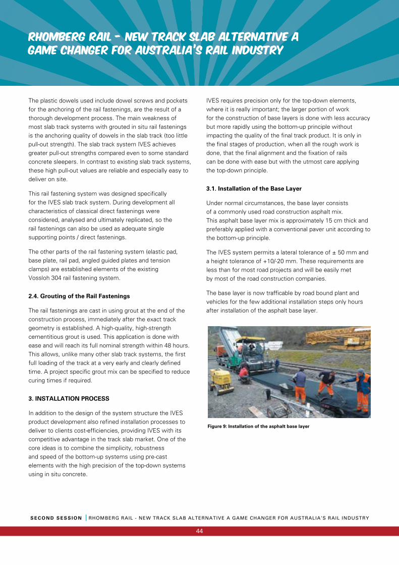
RHOMBERG RAIL - NEW TRACK SLAB ALTERNATIVE a GAME CHANGER FOR AUSTRALIA’S RAIL INDUSTRY
S E C O N D S E S S I O N I RHOMBERG RAIL - NEW TRACK SLAB ALTERNATIVE A GAME CHANGER FOR AUSTRALIA’S RAIL INDUSTRY
44
The plastic dowels used include dowel screws and pockets for the anchoring of the rail fastenings, are the result of a thorough development process. The main weakness of most slab track systems with grouted in situ rail fastenings is the anchoring quality of dowels in the slab track (too little pull-out strength). The slab track system IVES achieves greater pull-out strengths compared even to some standard concrete sleepers. In contrast to existing slab track systems, these high pull-out values are reliable and especially easy to deliver on site.
This rail fastening system was designed specifically for the IVES slab track system. During development all characteristics of classical direct fastenings were considered, analysed and ultimately replicated, so the rail fastenings can also be used as adequate single supporting points / direct fastenings.
The other parts of the rail fastening system (elastic pad, base plate, rail pad, angled guided plates and tension clamps) are established elements of the existing Vossloh 304 rail fastening system.
2.4. Grouting of the Rail Fastenings
The rail fastenings are cast in using grout at the end of the construction process, immediately after the exact track geometry is established. A high-quality, high-strength cementitious grout is used. This application is done with ease and will reach its full nominal strength within 48 hours. This allows, unlike many other slab track systems, the first full loading of the track at a very early and clearly defined time. A project specific grout mix can be specified to reduce curing times if required.
3. INSTALLATION PROCESS
In addition to the design of the system structure the IVES product development also refined installation processes to deliver to clients cost-efficiencies, providing IVES with its competitive advantage in the track slab market. One of the core ideas is to combine the simplicity, robustness and speed of the bottom-up systems using pre-cast elements with the high precision of the top-down systems using in situ concrete.
IVES requires precision only for the top-down elements, where it is really important; the larger portion of work for the construction of base layers is done with less accuracy but more rapidly using the bottom-up principle without impacting the quality of the final track product. It is only in the final stages of production, when all the rough work is done, that the final alignment and the fixation of rails can be done with ease but with the utmost care applying the top-down principle.
3.1. Installation of the Base Layer
Under normal circumstances, the base layer consists of a commonly used road construction asphalt mix. This asphalt base layer mix is approximately 15 cm thick and preferably applied with a conventional paver unit according to the bottom-up principle.
The IVES system permits a lateral tolerance of ± 50 mm and a height tolerance of +10/-20 mm. These requirements areless than for most road projects and will be easily metby most of the road construction companies.
The base layer is now trafficable by road bound plant and vehicles for the few additional installation steps only hours after installation of the asphalt base layer.
Figure 9: Installation of the asphalt base layer
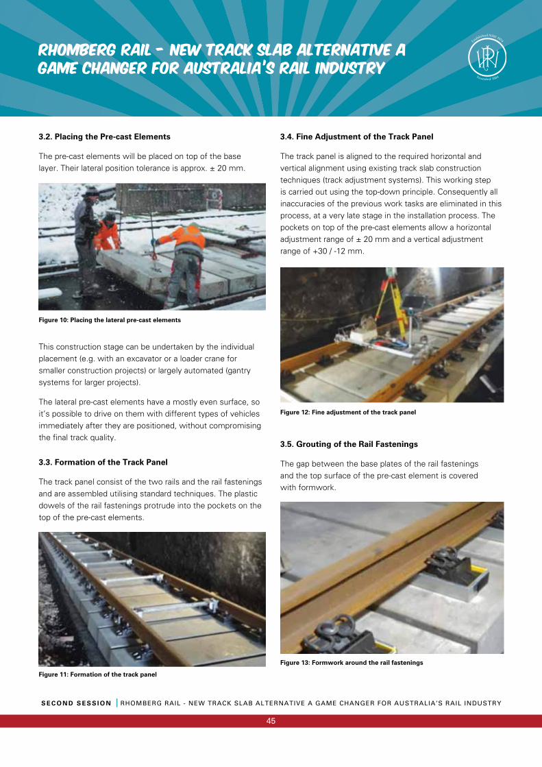
S E C O N D S E S S I O N I RHOMBERG RAIL - NEW TRACK SLAB ALTERNATIVE A GAME CHANGER FOR AUSTRALIA’S RAIL INDUSTRY
45
RHOMBERG RAIL - NEW TRACK SLAB ALTERNATIVE a GAME CHANGER FOR AUSTRALIA’S RAIL INDUSTRY
3.2. Placing the Pre-cast Elements
The pre-cast elements will be placed on top of the base layer. Their lateral position tolerance is approx. ± 20 mm.
Figure 10: Placing the lateral pre-cast elements
This construction stage can be undertaken by the individual placement (e.g. with an excavator or a loader crane for smaller construction projects) or largely automated (gantry systems for larger projects).
The lateral pre-cast elements have a mostly even surface, so it’s possible to drive on them with different types of vehicles immediately after they are positioned, without compromising the final track quality.
3.3. Formation of the Track Panel
The track panel consist of the two rails and the rail fastenings and are assembled utilising standard techniques. The plastic dowels of the rail fastenings protrude into the pockets on the top of the pre-cast elements.
Figure 11: Formation of the track panel
3.4. Fine Adjustment of the Track Panel
The track panel is aligned to the required horizontal and vertical alignment using existing track slab construction techniques (track adjustment systems). This working step is carried out using the top-down principle. Consequently all inaccuracies of the previous work tasks are eliminated in this process, at a very late stage in the installation process. The pockets on top of the pre-cast elements allow a horizontal adjustment range of ± 20 mm and a vertical adjustment range of +30 / -12 mm.
Figure 12: Fine adjustment of the track panel
3.5. Grouting of the Rail Fastenings
The gap between the base plates of the rail fastenings and the top surface of the pre-cast element is covered with formwork.
Figure 13: Formwork around the rail fastenings
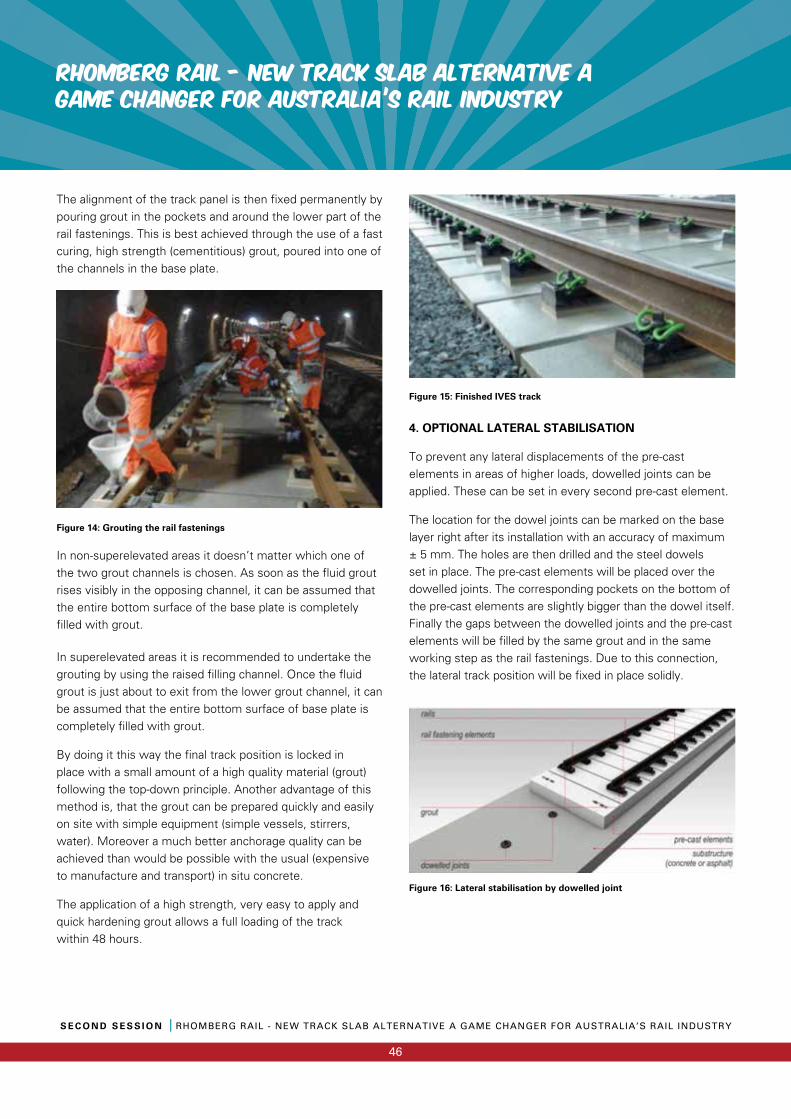
RHOMBERG RAIL - NEW TRACK SLAB ALTERNATIVE a GAME CHANGER FOR AUSTRALIA’S RAIL INDUSTRY
S E C O N D S E S S I O N I RHOMBERG RAIL - NEW TRACK SLAB ALTERNATIVE A GAME CHANGER FOR AUSTRALIA’S RAIL INDUSTRY
46
The alignment of the track panel is then fixed permanently by pouring grout in the pockets and around the lower part of the rail fastenings. This is best achieved through the use of a fast curing, high strength (cementitious) grout, poured into one of the channels in the base plate.
Figure 14: Grouting the rail fastenings
In non-superelevated areas it doesn’t matter which one of the two grout channels is chosen. As soon as the fluid grout rises visibly in the opposing channel, it can be assumed that the entire bottom surface of the base plate is completely filled with grout.
In superelevated areas it is recommended to undertake the grouting by using the raised filling channel. Once the fluid grout is just about to exit from the lower grout channel, it can be assumed that the entire bottom surface of base plate is completely filled with grout.
By doing it this way the final track position is locked in place with a small amount of a high quality material (grout) following the top-down principle. Another advantage of this method is, that the grout can be prepared quickly and easily on site with simple equipment (simple vessels, stirrers, water). Moreover a much better anchorage quality can be achieved than would be possible with the usual (expensive to manufacture and transport) in situ concrete.
The application of a high strength, very easy to apply and quick hardening grout allows a full loading of the track within 48 hours.
Figure 15: Finished IVES track
4. OPTIONAL LATERAL STABILISATION
To prevent any lateral displacements of the pre-cast elements in areas of higher loads, dowelled joints can be applied. These can be set in every second pre-cast element.
The location for the dowel joints can be marked on the base layer right after its installation with an accuracy of maximum ± 5 mm. The holes are then drilled and the steel dowels set in place. The pre-cast elements will be placed over the dowelled joints. The corresponding pockets on the bottom of the pre-cast elements are slightly bigger than the dowel itself. Finally the gaps between the dowelled joints and the pre-cast elements will be filled by the same grout and in the same working step as the rail fastenings. Due to this connection, the lateral track position will be fixed in place solidly.
Figure 16: Lateral stabilisation by dowelled joint
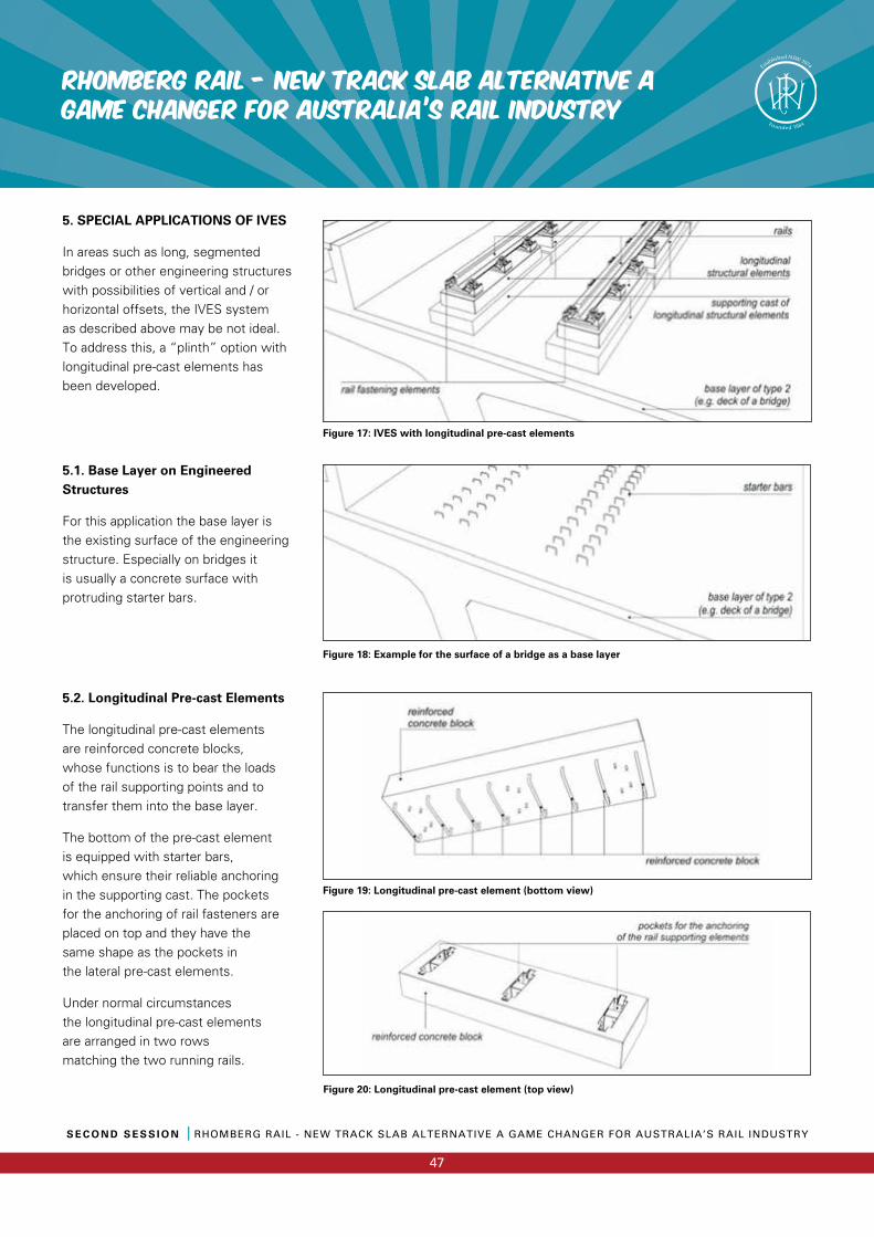
S E C O N D S E S S I O N I RHOMBERG RAIL - NEW TRACK SLAB ALTERNATIVE A GAME CHANGER FOR AUSTRALIA’S RAIL INDUSTRY
47
RHOMBERG RAIL - NEW TRACK SLAB ALTERNATIVE a GAME CHANGER FOR AUSTRALIA’S RAIL INDUSTRY
5. SPECIAL APPLICATIONS OF IVES
In areas such as long, segmented bridges or other engineering structures with possibilities of vertical and / or horizontal offsets, the IVES system as described above may be not ideal. To address this, a “plinth” option with longitudinal pre-cast elements has been developed.
5.1. Base Layer on Engineered Structures
For this application the base layer is the existing surface of the engineering structure. Especially on bridges it is usually a concrete surface with protruding starter bars.
Figure 17: IVES with longitudinal pre-cast elements
Figure 18: Example for the surface of a bridge as a base layer
5.2. Longitudinal Pre-cast Elements
The longitudinal pre-cast elementsare reinforced concrete blocks,whose functions is to bear the loads of the rail supporting points and to transfer them into the base layer.
The bottom of the pre-cast element is equipped with starter bars, which ensure their reliable anchoring in the supporting cast. The pockets for the anchoring of rail fasteners are placed on top and they have the same shape as the pockets in the lateral pre-cast elements.
Under normal circumstances the longitudinal pre-cast elements are arranged in two rows matching the two running rails.
Figure 20: Longitudinal pre-cast element (top view)
Figure 19: Longitudinal pre-cast element (bottom view)
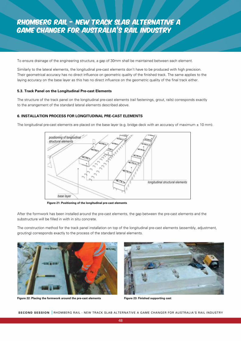
RHOMBERG RAIL - NEW TRACK SLAB ALTERNATIVE a GAME CHANGER FOR AUSTRALIA’S RAIL INDUSTRY
S E C O N D S E S S I O N I RHOMBERG RAIL - NEW TRACK SLAB ALTERNATIVE A GAME CHANGER FOR AUSTRALIA’S RAIL INDUSTRY
48
To ensure drainage of the engineering structure, a gap of 30mm shall be maintained between each element.
Similarly to the lateral elements, the longitudinal pre-cast elements don’t have to be produced with high precision. Their geometrical accuracy has no direct influence on geometric quality of the finished track. The same applies to the laying accuracy on the base layer as this has no direct influence on the geometric quality of the final track either.
5.3. Track Panel on the Longitudinal Pre-cast Elements
The structure of the track panel on the longitudinal pre-cast elements (rail fastenings, grout, rails) corresponds exactly to the arrangement of the standard lateral elements described above.
6. INSTALLATION PROCESS FOR LONGITUDINAL PRE-CAST ELEMENTS
The longitudinal pre-cast elements are placed on the base layer (e.g. bridge deck with an accuracy of maximum ± 10 mm).
After the formwork has been installed around the pre-cast elements, the gap between the pre-cast elements and the substructure will be filled in with in situ concrete.
The construction method for the track panel installation on top of the longitudinal pre-cast elements (assembly, adjustment, grouting) corresponds exactly to the process of the standard lateral elements.
Figure 21: Positioning of the longitudinal pre-cast elements
Figure 22: Placing the formwork around the pre-cast elements Figure 23: Finished supporting cast
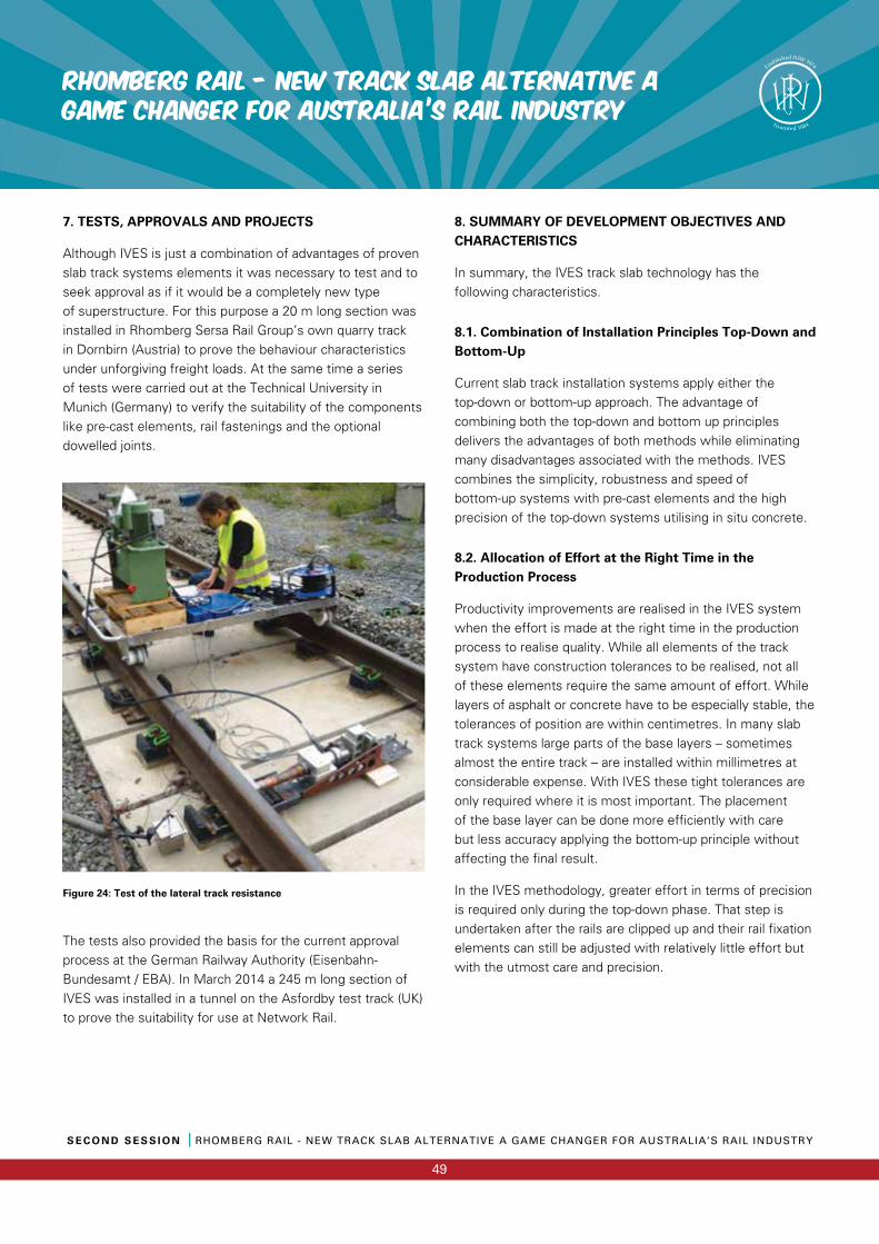
S E C O N D S E S S I O N I RHOMBERG RAIL - NEW TRACK SLAB ALTERNATIVE A GAME CHANGER FOR AUSTRALIA’S RAIL INDUSTRY
49
RHOMBERG RAIL - NEW TRACK SLAB ALTERNATIVE a GAME CHANGER FOR AUSTRALIA’S RAIL INDUSTRY
7. TESTS, APPROVALS AND PROJECTS
Although IVES is just a combination of advantages of proven slab track systems elements it was necessary to test and to seek approval as if it would be a completely new type of superstructure. For this purpose a 20 m long section was installed in Rhomberg Sersa Rail Group’s own quarry track in Dornbirn (Austria) to prove the behaviour characteristics under unforgiving freight loads. At the same time a series of tests were carried out at the Technical University in Munich (Germany) to verify the suitability of the components like pre-cast elements, rail fastenings and the optional dowelled joints.
Figure 24: Test of the lateral track resistance
The tests also provided the basis for the current approval process at the German Railway Authority (Eisenbahn-Bundesamt / EBA). In March 2014 a 245 m long section of IVES was installed in a tunnel on the Asfordby test track (UK) to prove the suitability for use at Network Rail.
8. SUMMARY OF DEVELOPMENT OBJECTIVES AND CHARACTERISTICS
In summary, the IVES track slab technology has the following characteristics.
8.1. Combination of Installation Principles Top-Down and Bottom-Up
Current slab track installation systems apply either the top-down or bottom-up approach. The advantage of combining both the top-down and bottom up principles delivers the advantages of both methods while eliminating many disadvantages associated with the methods. IVES combines the simplicity, robustness and speed of bottom-up systems with pre-cast elements and the high precision of the top-down systems utilising in situ concrete.
8.2. Allocation of Effort at the Right Time in the Production Process
Productivity improvements are realised in the IVES system when the effort is made at the right time in the production process to realise quality. While all elements of the track system have construction tolerances to be realised, not all of these elements require the same amount of effort. While layers of asphalt or concrete have to be especially stable, the tolerances of position are within centimetres. In many slab track systems large parts of the base layers – sometimes almost the entire track – are installed within millimetres at considerable expense. With IVES these tight tolerances are only required where it is most important. The placement of the base layer can be done more efficiently with care but less accuracy applying the bottom-up principle without affecting the final result.
In the IVES methodology, greater effort in terms of precision is required only during the top-down phase. That step is undertaken after the rails are clipped up and their rail fixation elements can still be adjusted with relatively little effort but with the utmost care and precision.
RHOMBERG RAIL - NEW TRACK SLAB ALTERNATIVE a GAME CHANGER FOR AUSTRALIA’S RAIL INDUSTRY
S E C O N D S E S S I O N I RHOMBERG RAIL - NEW TRACK SLAB ALTERNATIVE A GAME CHANGER FOR AUSTRALIA’S RAIL INDUSTRY
50
8.3. Appropriate Use of Quality of Material and Components
While the traffic loads are concentrated in the upper track components (rails and its fastening elements), these loads spread and decrease rapidly with depth. Similarly, in regards to accuracy, the precision of the upper componentry has a direct effect on the vehicle track guiding and is increasing in importance as line speed is increased. The precision of base layers below the rail plays a minor role in most cases with regards to the performance of the track system.
Some non-ballasted track designs, including large block segments potentially including the entire track structure, are prefabricated at the factory individually for each respective project requirement requiring high accuracy and quality. These large units are then transported and installed with significant logistical effort. In other systems, where most fabrication is completed in situ, there are often problems with the quality of anchoring the rail fastening elements.
A key feature of IVES is the appropriate use of specially engineered quality materials and components. The requirements on accuracy for the base layers (usually made of asphalt) correspond to those of the ordinary road construction. The sleeper-like structural elements are prefabricated, which in turn ensures a high quality of material and enables rapid installation. However the requirements on accuracy for their production are relatively low allowing the use of ordinary prefabrication techniques. Even their shape is independent of the type of rail, of rail inclination and of track gauge to a certain degree, which turns them into very versatile components. The precisely manufactured rail fastenings and their high-quality anchorage in the precast elements achieve all requirements for modern slab track systems for high speed lines without compromise.
8.4 Appropriate Simplification of Components
The appropriate quality of components, in particular the prefabricated and sleeper-like pre-cast elements of the track follow simplified design principles. The quality of material is adequately high, but the production accuracy requirement is low and the achieved shape relatively simple. This brings favourable economic and financial benefits to the IVES methodology.
8.5. Simplification and Increased Flexibility of Installation Process
Most of the installation processes of IVES are simple and can be implemented as a continuous routine process. This simplification of processes leads to opportunities for a high level of mechanisation and therefore high daily production rates.
Furthermore the dependencies between each production steps become less important. The installation steps become more independent so that the installation process to interruptions at any stage don’t result in a significant increase in expense or complications.
On the other hand, the individual installation steps can be done consecutively or with a short delay, say a few hours. Unlike other track slab systems, waiting times for days or weeks between the installation steps or until initial loading have been eliminated.
This is of great benefit on small construction projects, in which a fast start-up has priority instead of continuous routine processes. Large projects, with a focus on increasing efficiency of individual operations, can be organised very flexibly and individually.
8.6. Use of Known, Proven Materials and Methods
During the design development phase of IVES, best practice was researched across both road and rail bodies of knowledge. For example:
a) The base layer adopted in the IVES system was modelled on the road construction methodology.
b) The pre-cast elements are manufactured using precast concrete construction methodologies
c) The rail fastening elements are generally based on existing components, which have been proven over decades.

The UNSUNG Heroes
The UNSUNG Heroes
2016 ALAN BARHAM MAINTENANCE TEAM AWARD
S E C O N D S E S S I O N I A L A N B A R H A M M A I N T E N A N C E T E A M A W A R D
51
Alan Barham commenced service as a trainee civil engineer
with the NSW Government Railways in 1965.
He spent time at Cowra as a District Engineer before
becoming Division Engineer Tamworth, a position he held for
several years.
When FreightRail was created in 1989 Alan became the
Infrastructure Engineering Manager and continued in that
position until June 1996 when he joined the newly created
Rail Access Corporation as Senior Asset Manager for the
Hunter, North Coast and North West areas.
Alan died in early 1997 from cancer.
Alan was an advocate of the importance of the local
Housekeeping/Routine maintenance from fettling gangs to
safety, reliability and the condition of the Railway. It was
for this reason that the PWI named the Maintenance Team
Award (or Best Kept Length as it was formerly known)
in his honour.
The Award was established to promote pride in maintenance
of the track and associated structures. While Alan was a
Committee Member of the PWI he promoted this Award
throughout the State and was also involved in the judging.
A typical Routine Maintenance team undertakes surveillance
inspections, servicing, minor corrective maintenance and
emergency response, for track, bridges, right of way assets
and possibly signal assets. The team needs to be operating
in NSW.
Judging Criteria
The period under consideration is based on the financial
year preceding the annual convention. Applicants will be
assessed against People, Organisation and Leadership and
Achievement criteria. The judges will evaluate outcomes and
conditions which are within the Maintenance Team’s control
as far as possible. It is recognised that track configuration,
investment programs, operating parameters, and to a large
extent general infrastructure conditions are outside the
Maintenance Team’s control.
The Judges seek to identify the best use of management and
technical expertise, and the most effective use of resources,
in maintaining the track to meet operational requirements.
Applicants should describe the reasons why the nominated
team deserves to be recognised for excellence in Routine
Maintenance, and provide supporting documentation where
possible. How has the maintenance workforce made a
difference? How have they contributed to extraordinary
outcomes? What innovations have they introduced?
The following performance areas are examples from which
applicants may select those they wish to claim superior
outcomes. Applications will be assessed from nomination
documentation, site visits to short listed nominated teams,
reference checks and other relevant sources of information.
Ken Lingabala, Manager Infrastructure, John Holland Rail CRN
David Scealy, Maintenance Superintendent, John Holland Rail CRN
Phil Grant, Possession Delivery and Access Manager, Sydney Trains
Scott Chapman, General Manager Asset Delivery, ARTC
Stuart Sutherland, Managing Director, Lycopodium Rail
Judges
S E C O N D S E S S I O N I A L A N B A R H A M M A I N T E N A N C E T E A M A W A R D
52
2016 ALAN BARHAM MAINTENANCE TEAM AWARD
1. Team Leadership, readiness and engagement
• Capability
• Responsiveness and commitment
• Engagement
• Succession planning
• Leadership
2. Compliance and assurance
• Workplace safety
• Infrastructure compliance
• Operational assurance
• Environmental compliance
3. Productivity (effectiveness and efficiency)
• Scoping
• Short term work planning (2-3 weeks)
• Long term work planning (12+months)
• Strategic engagement
• Effi ciency strategies
4. Achievement
• Innovation
• Challenge
Alan Barham Maintenance Team Award – 2016 Entries
Metropolitan
Sydney Trains – Lawson Civil Team
Sydney Trains – Sydenham Civil Team
Regional
ARTC – Wagga Wagga Provisioning Centre
ARTC – Coffs Harbour Provisioning Centre
JHR CRN – West Wyalong Routine Maintenance Team
JHR CRN – Nyngan Routine Maintenance Team
We have six teams nominated this year, two each from Sydney Trains, John Holland CRN and ARTC. We continue to see each year high quality submissions put forward by each team. The track maintained by the nominated teams consisted of heavily traffi cked concrete sleepered electrifi ed CWR track to steel sleepered track not so heavily traffi cked section. The maintenance standard of all six teams were of very high calibre and their commitments to work is outstanding. All the teams who have participated in this year’s award are to be congratulated for their outstanding performance.
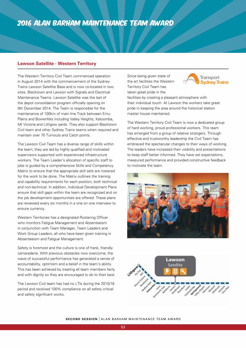
2016 ALAN BARHAM MAINTENANCE TEAM AWARD
S E C O N D S E S S I O N I A L A N B A R H A M M A I N T E N A N C E T E A M A W A R D
53
The Western Territory Civil Team commenced operation in August 2014 with the commencement of the Sydney Trains Lawson Satellite Base and is now co-located in two sites, Blacktown and Lawson with Signals and Electrical Maintenance Teams. Lawson Satellite was the last of the depot consolidation program officially opening on 9th December 2014. The Team is responsible for the maintenance of 100km of main line Track between Emu Plains and Bowenfels including Valley Heights, Katoomba, Mt Victoria and Lithgow yards. They also support Blacktown Civil team and other Sydney Trains teams when required and maintain over 70 Turnouts and Catch points.
The Lawson Civil Team has a diverse range of skills within the team; they are led by highly qualified and motivated supervisors supported with experienced infrastructure workers. The Team Leader’s allocation of specific staff to jobs is guided by a comprehensive Skills and Competency Matrix to ensure that the appropriate skill sets are rostered for the work to be done. The Matrix outlines the training and capability requirements for each position, both technical and non-technical. In addition, Individual Development Plans ensure that skill gaps within the team are recognized and on the job development opportunities are offered. These plans are reviewed every six months in a one on one interview to ensure currency.
Western Territories has a designated Rostering Officer who monitors Fatigue Management and Absenteeism in conjunction with Team Manager, Team Leaders and Work Group Leaders, all who have been given training in Absenteeism and Fatigue Management.
Safety is foremost and the culture is one of frank, friendly camaraderie. With previous obstacles now overcome, the wave of successful performance has generated a sense of accountability, optimism and a belief in the team’s ability. This has been achieved by treating all team members fairly and with dignity so they are encouraged to do to their best.
The Lawson Civil team has had no LTls during the 2015/16 period and received 100% compliance on all safety critical and safety significant works.
Since being given state of the art facilities the Western Territory Civil Team has taken great pride in the facilities by creating a pleasant atmosphere with their individual touch. At Lawson the workers take great pride in keeping the area around the historical station master house maintained.
The Western Territory Civil Team is now a dedicated group of hard working, proud professional workers. This team has emerged from a group of relative strangers. Through effective and trustworthy leadership the Civil Team has embraced the spectacular changes to their ways of working. The leaders have increased their visibility and presentations to keep staff better informed. They have set expectations, measured performance and provided constructive feedback to motivate the team.
Lawson Satellite - Western Territory
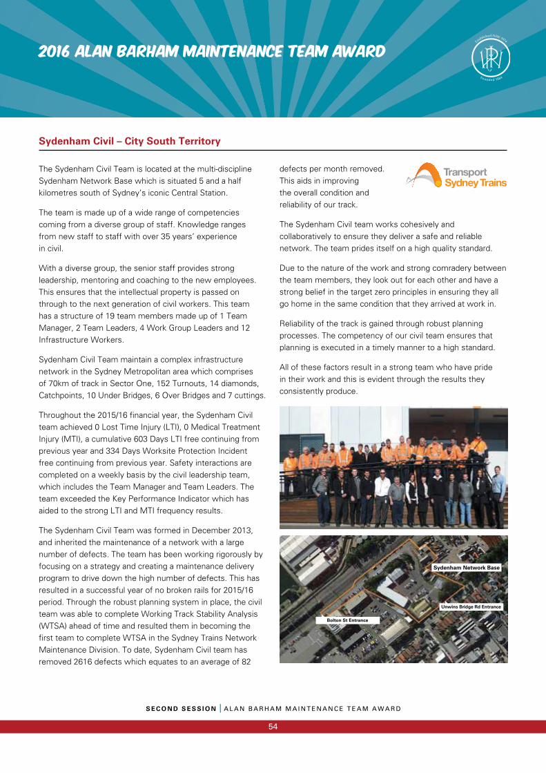
S E C O N D S E S S I O N I A L A N B A R H A M M A I N T E N A N C E T E A M A W A R D
54
2016 ALAN BARHAM MAINTENANCE TEAM AWARD
The Sydenham Civil Team is located at the multi-discipline Sydenham Network Base which is situated 5 and a half kilometres south of Sydney’s iconic Central Station.
The team is made up of a wide range of competencies coming from a diverse group of staff. Knowledge ranges from new staff to staff with over 35 years’ experiencein civil.
With a diverse group, the senior staff provides strong leadership, mentoring and coaching to the new employees. This ensures that the intellectual property is passed on through to the next generation of civil workers. This team has a structure of 19 team members made up of 1 Team Manager, 2 Team Leaders, 4 Work Group Leaders and 12 Infrastructure Workers.
Sydenham Civil Team maintain a complex infrastructure network in the Sydney Metropolitan area which comprises of 70km of track in Sector One, 152 Turnouts, 14 diamonds, Catchpoints, 10 Under Bridges, 6 Over Bridges and 7 cuttings.
Throughout the 2015/16 financial year, the Sydenham Civil team achieved 0 Lost Time Injury (LTI), 0 Medical Treatment Injury (MTI), a cumulative 603 Days LTI free continuing from previous year and 334 Days Worksite Protection Incident free continuing from previous year. Safety interactions are completed on a weekly basis by the civil leadership team, which includes the Team Manager and Team Leaders. The team exceeded the Key Performance Indicator which has aided to the strong LTI and MTI frequency results.
The Sydenham Civil Team was formed in December 2013, and inherited the maintenance of a network with a large number of defects. The team has been working rigorously by focusing on a strategy and creating a maintenance delivery program to drive down the high number of defects. This has resulted in a successful year of no broken rails for 2015/16 period. Through the robust planning system in place, the civil team was able to complete Working Track Stability Analysis (WTSA) ahead of time and resulted them in becoming the first team to complete WTSA in the Sydney Trains Network Maintenance Division. To date, Sydenham Civil team has removed 2616 defects which equates to an average of 82
defects per month removed. This aids in improving the overall condition and reliability of our track.
The Sydenham Civil team works cohesively and collaboratively to ensure they deliver a safe and reliable network. The team prides itself on a high quality standard.
Due to the nature of the work and strong comradery between the team members, they look out for each other and have a strong belief in the target zero principles in ensuring they all go home in the same condition that they arrived at work in.
Reliability of the track is gained through robust planning processes. The competency of our civil team ensures that planning is executed in a timely manner to a high standard.
All of these factors result in a strong team who have pride in their work and this is evident through the results they consistently produce.
Sydenham Civil – City South Territory
Sydenham Network Base
Unwins Bridge Rd Entrance
Bolton St Entrance
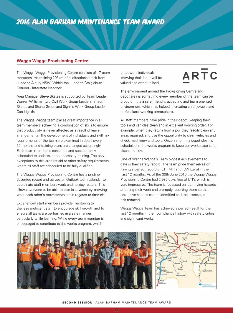
2016 ALAN BARHAM MAINTENANCE TEAM AWARD
S E C O N D S E S S I O N I A L A N B A R H A M M A I N T E N A N C E T E A M A W A R D
55
The Wagga Wagga Provisioning Centre consists of 17 team members, maintaining 203km of bi-directional track from Junee to Albury NSW. Within the Junee to Craigieburn Corridor - Interstate Network
Area Manager Steve Skates is supported by Team Leader Warren Williams, two Civil Work Group Leaders; Shaun Skates and Shane Green and Signals Work Group Leader Con Ligakis.
The Wagga Wagga team places great importance in all team members achieving a combination of skills to ensure that productivity is never affected as a result of leave arrangements. The development of individuals and skill mix requirements of the team are examined in detail every 12 months and training plans are changed accordingly. Each team member is consulted and subsequently scheduled to undertake the necessary training. The only exceptions to this are first aid or other safety requirements where all staff are scheduled to be fully qualified.
The Wagga Wagga Provisioning Centre has a pristine absentee record and utilizes an Outlook team calendar to coordinate staff members work and holiday rosters. This allows everyone to be able to plan in advance by knowing what each other’s movements are in regards to time off.
Experienced staff members provide mentoring to the less proficient staff to encourage skill growth and to ensure all tasks are performed in a safe manner, particularly while learning. While every team member is encouraged to contribute to the works program, which
empowers individuals knowing their input will be valued and often utilised.
The environment around the Provisioning Centre and depot area is something every member of the team can be proud of. It is a safe, friendly, accepting and team oriented environment, which has helped in creating an enjoyable and professional working atmosphere.
All staff members have pride in their depot, keeping their tools and vehicles clean and in excellent working order. For example, when they return from a job, they readily clean any areas required, and use the opportunity to clean vehicles and check machinery and tools. Once a month, a depot clean is scheduled in the works program to keep our workspace safe, clean and tidy.
One of Wagga Wagga’s Team biggest achievements to date is their safety record. The team pride themselves on having a perfect record of LTI, MTI and FAN (zero) in the last 12 months. As of the 30th June 2016 the Wagga Wagga Provisioning Centre had 2,930 days free of LTI’s which is very impressive. The team is focussed on identifying hazards affecting their work and promptly reporting them so that corrective actions can be identified and the associatedrisk reduced.
Wagga Wagga Team has achieved a perfect result for the last 12 months in their compliance history with safety critical and significant works.
Wagga Wagga Provisioning Centre
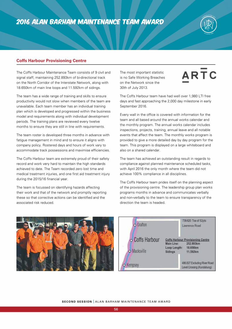
S E C O N D S E S S I O N I A L A N B A R H A M M A I N T E N A N C E T E A M A W A R D
56
2016 ALAN BARHAM MAINTENANCE TEAM AWARD
The Coffs Harbour Maintenance Team consists of 9 civil and signal staff, maintaining 252.893km of bi-directional track on the North Corridor of the Interstate Network, along with 18.650km of main line loops and 11.592km of sidings.
The team has a wide range of training and skills to ensure productivity would not slow when members of the team are unavailable. Each team member has an individual training plan which is developed and progressed within the business model and requirements along with individual development periods. The training plans are reviewed every twelve months to ensure they are still in line with requirements.
The team roster is developed three months in advance with fatigue management in mind and to ensure it aligns with company policy. Rostered days and hours of work vary to accommodate track possessions and maximise efficiencies.
The Coffs Harbour team are extremely proud of their safety record and work very hard to maintain the high standards achieved to date. The Team recorded zero lost time and medical treatment injuries, and one first aid treatment injury during the 2015/16 financial year.
The team is focussed on identifying hazards affecting their work and that of the network and promptly reporting these so that corrective actions can be identified and the associated risk reduced.
The most important statistic is no Safe Working Breaches on the Network since the 30th of July 2013.
The Coffs Harbour team have had well over 1,980 LTI free days and fast approaching the 2,000 day milestone in early September 2016.
Every wall in the office is covered with information for the team and all based around the annual works calendar and the monthly program. The annual works calendar includes inspections, projects, training, annual leave and all notable events that affect the team. The monthly works program is provided to give a more detailed day by day program for the team. This program is displayed on a large whiteboard and also on a shared calendar.
The team has achieved an outstanding result in regards to compliance against planned maintenance scheduled tasks, with April 2016 the only month where the team did not achieve 100% compliance in all disciplines.
The Coffs Harbour team prides itself on the planning aspect of the provisioning centre. The leadership group plan works programs months in advance and communicates verbally and non-verbally to the team to ensure transparency of the direction the team is headed.
Coffs Harbour Provisioning Centre
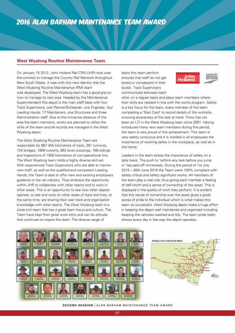
2016 ALAN BARHAM MAINTENANCE TEAM AWARD
S E C O N D S E S S I O N I A L A N B A R H A M M A I N T E N A N C E T E A M A W A R D
57
On January 15 2012, John Holland Rail CRN (JHR) took over the contract to manage the Country Rail Network throughout New South Wales. It was with this new identity that the West Wyalong Routine Maintenance (RM) team was developed. The West Wyalong team has a good grip on how to manage its vast area. Headed by the Maintenance Superintendent this depot is the main staff base with four Track Supervisors, one Planner/Scheduler, one Engineer, four Leading Hands, 17 Maintainers, one Structures and three Administration staff. Due to the immense distance of the area the team maintains, works are planned to utilise the skills of the team and all records are managed in the West Wyalong depot.
The West Wyalong Routine Maintenance Team are responsible for 967.455 kilometres of track, 281 turnouts, 124 bridges, 1809 culverts, 863 level crossings, 168 sidings and inspections of 1000 kilometres of non-operational line. The West Wyalong team holds a highly diverse skill set. With experienced Track Supervisors who are able to mentor new staff, as well as the qualified and competent Leading Hands, the Team is able to offer new and existing employees guidance in the rail industry. They embrace the opportunity within JHR to collaborate with other teams and to work in other areas. This is an opportunity to see how other depots operate, to see and work on other areas of track and they, at the same time, are sharing their vast track and organisation knowledge with other teams. The West Wyalong team is a close knit team that has a great team focus and culture. The Team have kept their great work ethic and can do attitude that continues to inspire the team. The diverse range of
tasks this team perform ensures that staff do not get bored or complacent in their duties. Track Supervisors communicate between each other on a regular basis and place team members where their skills are needed in line with the works program. Safety is a key focus for the team, every member of the team completing a ‘Start Card’ to record details of the worksite, ensuring awareness of the task at hand. There has not been an LTI in the West Wyalong team since 2001. Having introduced many new team members during this period, the team is very proud of this achievement. This team is very safety conscious and it is instilled in all employees the importance of working safely in the workplace, as well as in the home.
Leaders in the team stress the importance of safety on a daily basis. The push to ‘rethink any task before you jump in’ has paid off immensely. During the period of 1st July 2015 – 30th June 2016 the Team were 100% compliant with safety critical and safety significant works. All members of the team play a vital role; thus giving each member a feeling of self-worth and a sense of ownership of the asset. This is displayed in the quality of work they perform. It is evident that this sense of ownership over the asset gives a great sense of pride to the individual which is what makes this team so successful. West Wyalong depot make a huge effort in keeping the depot well maintained and organised including keeping the vehicles washed and tidy. The team pride really shows every day in the way the depot operates.
West Wyalong Routine Maintenance Team
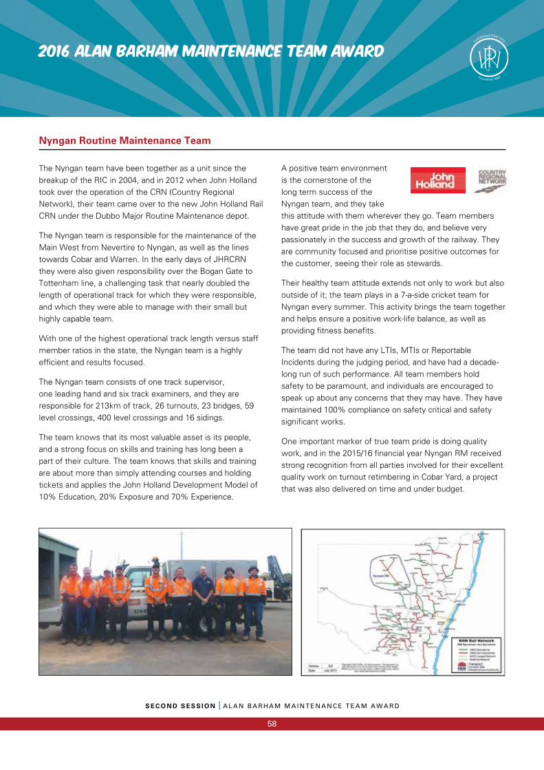
S E C O N D S E S S I O N I A L A N B A R H A M M A I N T E N A N C E T E A M A W A R D
58
2016 ALAN BARHAM MAINTENANCE TEAM AWARD
The Nyngan team have been together as a unit since the breakup of the RIC in 2004, and in 2012 when John Holland took over the operation of the CRN (Country Regional Network), their team came over to the new John Holland Rail CRN under the Dubbo Major Routine Maintenance depot.
The Nyngan team is responsible for the maintenance of the Main West from Nevertire to Nyngan, as well as the lines towards Cobar and Warren. In the early days of JHRCRN they were also given responsibility over the Bogan Gate to Tottenham line, a challenging task that nearly doubled the length of operational track for which they were responsible, and which they were able to manage with their small but highly capable team.
With one of the highest operational track length versus staff member ratios in the state, the Nyngan team is a highly efficient and results focused.
The Nyngan team consists of one track supervisor, one leading hand and six track examiners, and they are responsible for 213km of track, 26 turnouts, 23 bridges, 59 level crossings, 400 level crossings and 16 sidings.
The team knows that its most valuable asset is its people, and a strong focus on skills and training has long been a part of their culture. The team knows that skills and training are about more than simply attending courses and holding tickets and applies the John Holland Development Model of 10% Education, 20% Exposure and 70% Experience.
A positive team environment is the cornerstone of the long term success of the Nyngan team, and they take this attitude with them wherever they go. Team members have great pride in the job that they do, and believe very passionately in the success and growth of the railway. They are community focused and prioritise positive outcomes for the customer, seeing their role as stewards.
Their healthy team attitude extends not only to work but also outside of it; the team plays in a 7-a-side cricket team for Nyngan every summer. This activity brings the team together and helps ensure a positive work-life balance, as well as providing fitness benefits.
The team did not have any LTIs, MTIs or Reportable Incidents during the judging period, and have had a decade-long run of such performance. All team members hold safety to be paramount, and individuals are encouraged to speak up about any concerns that they may have. They have maintained 100% compliance on safety critical and safety significant works.
One important marker of true team pride is doing quality work, and in the 2015/16 financial year Nyngan RM received strong recognition from all parties involved for their excellent quality work on turnout retimbering in Cobar Yard, a project that was also delivered on time and under budget.
Nyngan Routine Maintenance Team

The UNSUNG Heroes
The UNSUNG Heroes
The Unsung Heroes – Panel Session
2016 Ken Erickson Innovation Award
2016 Steve Maxwell Platelaying Award
THIRDSessionTHIRD
SessionPWI Annual Convention 2016

Stewart Mills I Career Commenced 1985Executive Director Maintenance & Engineering at Sydney Trains
Stewart Mills is a 30+ year veteran of the rail industry, and is currently the Executive Director of Maintenance & Engineering at Sydney Trains. Prior to joining Sydney Trains, Stewart was the Tube Lines Director of Operations for London Underground’s Jubilee, Northern and Piccadilly Lines, where he was responsible for the maintenance and asset performance of the three lines, which included 225 passenger trains, track, legacy and the upgraded signalling system, along with 100 stations carrying over 2 million passengers a day. Prior to this, Stewart was also the Project Director for Amey Rail (for the CCA Consortium) on Section 1 of the Channel Tunnel Rail Link. Stewart is passionate about getting the best out of people and leading teams and organisations, and is equally inspired by a leader who inspires you to do great things.
Rowenna Walker I Career Commenced 1996Global Leader, Rail and Mass Transit, Aurecon
Rowenna is a qualified Chartered Civil Engineer with over 20 years of international experience, and is a graduate member of the Australian Institute of Company Directors. Rowenna started her rail career in 1996 with Balfour Beatty Rail as a Senior Site Engineer, and has built her career through roles in both the private and public sectors in the UK, Australia and NZ. In her current role with Aurecon, where she leads an international team of engineering professionals and is responsible for strategy, growth and performance on rail projects. Rowenna is most passionate about harnessing and realising talent that can benefit the engineering industry and ultimately society as a whole.
Julian Sharp I Career Commenced 1990Alliance General Manager of the Level Crossing Removal Project – Caulfield to Dandenong
Julian Sharp is a Chartered Railway Civil Engineer with over 25 years in the civil and rail engineering industry. He started his career following graduation from university as a graduate civil engineer and worked his way up through the management structure of Balfour Beatty to become a Project Manager. He was involved in a number of iconic projects in London including Westminster Station on the Jubilee Line in the mid 90s. In 20016, Julian arrived in Australia, where he worked on a number of key rail infrastructure projects with ARTC, TPD, Macmahon Rail and Leighton Contractors. Julian is a committee member of the NSW Permanent Way Institution and also the Secretary of the Pichi Richi Railway Preservation Society in Quorn South Australia.
Ian Prescotte I Career Commenced 1977Operation and Maintenance Manager, Laing O’Rourke
Like many railway men of his generation, Ian was introduced to the railways by his father. Starting his career as an OHW Linesman, Ian worked his way up the ranks through the electrical trade into leadership and supervisory roles. Not afraid to try anything, Ian has a license to drive anything (his words), and loves nothing more than to prove the doubter wrong, especially when they suggest he cannot achieve a project deliverable! He is passionate about maintaining a good work ethic, even in the difficult times of change and restructure, has been a mentor to many young railway staff, and prides himself on setting an example in work ethic, and his highs standards in quality and safety.
OPEN PANEL FORUM MEMBERS FOR 2016
T H I R D S E S S I O N I O P E N P A N E L F O R U M
59
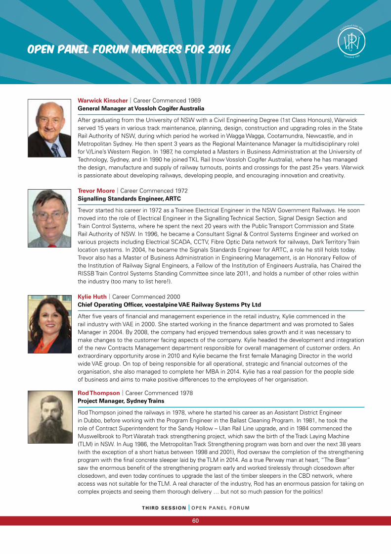
T H I R D S E S S I O N I O P E N P A N E L F O R U M
60
OPEN PANEL FORUM MEMBERS FOR 2016
Warwick Kinscher I Career Commenced 1969General Manager at Vossloh Cogifer Australia
After graduating from the University of NSW with a Civil Engineering Degree (1st Class Honours), Warwick served 15 years in various track maintenance, planning, design, construction and upgrading roles in the State Rail Authority of NSW, during which period he worked in Wagga Wagga, Cootamundra, Newcastle, and in Metropolitan Sydney. He then spent 3 years as the Regional Maintenance Manager (a multidisciplinary role) for V/Line’s Western Region. In 1987, he completed a Masters in Business Administration at the University of Technology, Sydney, and in 1990 he joined TKL Rail (now Vossloh Cogifer Australia), where he has managed the design, manufacture and supply of railway turnouts, points and crossings for the past 25+ years. Warwick is passionate about developing railways, developing people, and encouraging innovation and creativity.
Trevor Moore I Career Commenced 1972Signalling Standards Engineer, ARTC
Trevor started his career in 1972 as a Trainee Electrical Engineer in the NSW Government Railways. He soon moved into the role of Electrical Engineer in the Signalling Technical Section, Signal Design Section and Train Control Systems, where he spent the next 20 years with the Public Transport Commission and State Rail Authority of NSW. In 1996, he became a Consultant Signal & Control Systems Engineer and worked on various projects including Electrical SCADA, CCTV, Fibre Optic Data network for railways, Dark Territory Train location systems. In 2004, he became the Signals Standards Engineer for ARTC, a role he still holds today. Trevor also has a Master of Business Administration in Engineering Management, is an Honorary Fellow of the Institution of Railway Signal Engineers, a Fellow of the Institution of Engineers Australia, has Chaired the RISSB Train Control Systems Standing Committee since late 2011, and holds a number of other roles within the industry (too many to list here!).
Kylie Huth I Career Commenced 2000Chief Operating Offi cer, voestalpine VAE Railway Systems Pty Ltd
After fi ve years of fi nancial and management experience in the retail industry, Kylie commenced in the rail industry with VAE in 2000. She started working in the fi nance department and was promoted to Sales Manager in 2004. By 2008, the company had enjoyed tremendous sales growth and it was necessary to make changes to the customer facing aspects of the company. Kylie headed the development and integration of the new Contracts Management department responsible for overall management of customer orders. An extraordinary opportunity arose in 2010 and Kylie became the fi rst female Managing Director in the world wide VAE group. On top of being responsible for all operational, strategic and fi nancial outcomes of the organisation, she also managed to complete her MBA in 2014. Kylie has a real passion for the people side of business and aims to make positive differences to the employees of her organisation.
Rod Thompson I Career Commenced 1978Project Manager, Sydney Trains
Rod Thompson joined the railways in 1978, where he started his career as an Assistant District Engineer in Dubbo, before working with the Program Engineer in the Ballast Cleaning Program. In 1981, he took the role of Contract Superintendent for the Sandy Hollow – Ulan Rail Line upgrade, and in 1984 commenced the Muswellbrook to Port Waratah track strengthening project, which saw the birth of the Track Laying Machine (TLM) in NSW. In Aug 1986, the Metropolitan Track Strengthening program was born and over the next 38 years (with the exception of a short hiatus between 1998 and 2001), Rod oversaw the completion of the strengthening program with the fi nal concrete sleeper laid by the TLM in 2014. As a true Perway man at heart, “The Bear” saw the enormous benefi t of the strengthening program early and worked tirelessly through closedown after closedown, and even today continues to upgrade the last of the timber sleepers in the CBD network, where access was not suitable for the TLM. A real character of the industry, Rod has an enormous passion for taking on complex projects and seeing them thorough delivery … but not so much passion for the politics!
KEN ERICKSON INNOVATION AWARD 2016
T H I R D S E S S I O N I K E N E R I C K S O N I N N O V A T I O N A W A R D
61
Ken Erickson was elected as a Fellow of the New South Wales Permanent Way Institution on 30 November 1981. He was a
member of the Committee from 1981 until his untimely death on 25 November 1988. In his 7 years on the Committee he was
an Editor, with wry humour and then Secretary, with sparkling wit.
Ken was a dynamic member of the committee and a gifted speaker. His “summing up” of our only conference at Kings Cross
will always be remembered by those lucky enough to be present.
Ken was always trying to provide new ideas or concepts to the PWI, hence it is fitting that the Achievement Award, which
particularly looks for new ideas, is named in his honour.
This Annual Award is made to recognise an initiative or significant advance, which has been towards improvement in any part
of the Permanent Way Industry during the last year.
Eligible entries may be in the field of design, componentry, support systems (structural, geotechnical, surveying, mechanical,
interaction services) techniques, mechanisation or automation. The field is open to as wide a number of categories as possible.
Entries must have been completed in the last financial year by, or under control of a member of the NSW Section, whether on
a government or private railway system.
Judging is based on:
Scoring Category Available Score
Difficulties overcome 10
Contribution / Impact to track 20
Technical Input 20
Degree of innovation in Perway aspects 20
Contribution to Safety 10
WH&S Systems 10
Amount of Local / Australian input 10
Total Score / Marks 100
Michael Hickey, Rail Planning Services
Peter Boonstrs, CH2M
Bob Ford, Ford Rail Management Pty Ltd
Daniel Armstrong, Rail Planning Services
Judges

The UNSUNG Heroes
The UNSUNG Heroes
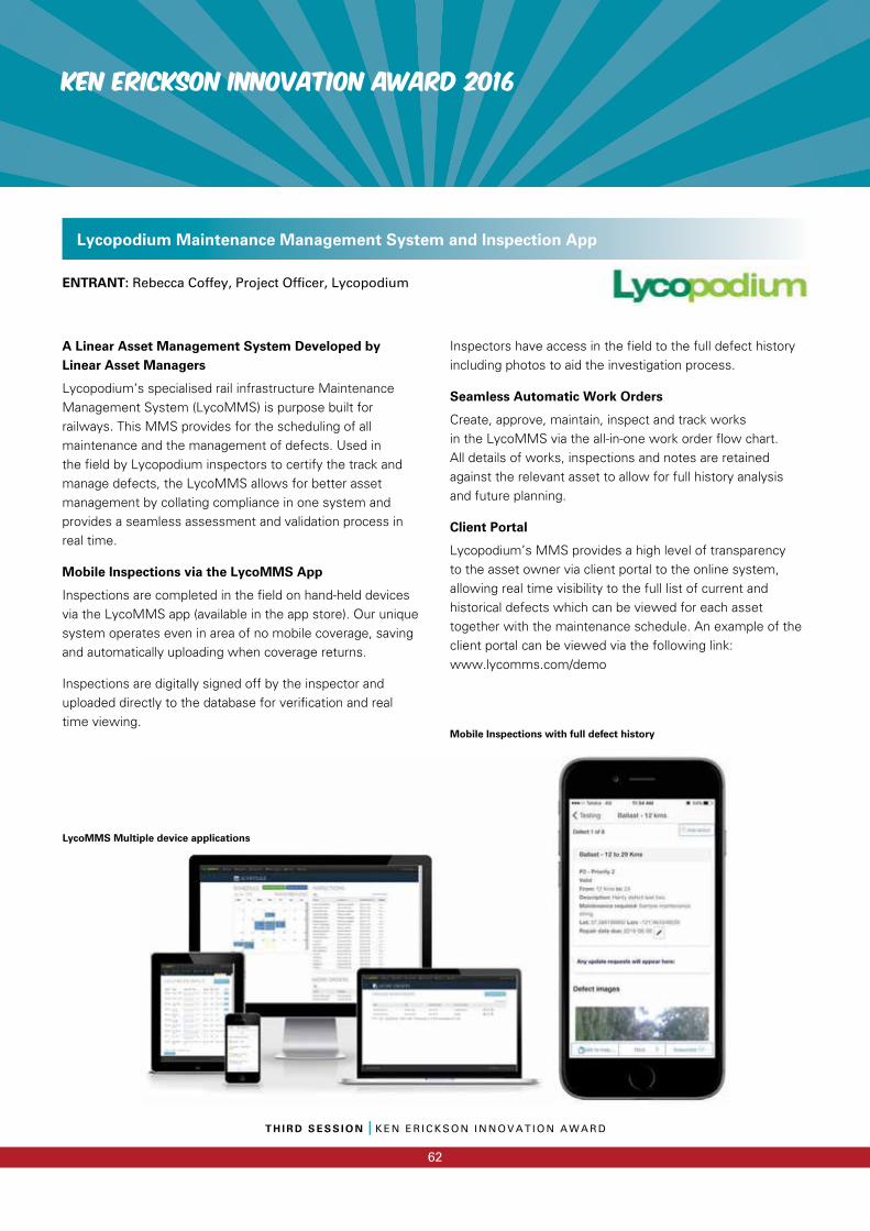
KEN ERICKSON INNOVATION AWARD 2016
T H I R D S E S S I O N I K E N E R I C K S O N I N N O V A T I O N A W A R D
62
A Linear Asset Management System Developed by Linear Asset Managers
Lycopodium’s specialised rail infrastructure Maintenance Management System (LycoMMS) is purpose built for railways. This MMS provides for the scheduling of all maintenance and the management of defects. Used in the field by Lycopodium inspectors to certify the track and manage defects, the LycoMMS allows for better asset management by collating compliance in one system and provides a seamless assessment and validation process in real time.
Mobile Inspections via the LycoMMS App
Inspections are completed in the field on hand-held devices via the LycoMMS app (available in the app store). Our unique system operates even in area of no mobile coverage, saving and automatically uploading when coverage returns.
Inspections are digitally signed off by the inspector and uploaded directly to the database for verification and real time viewing.
Inspectors have access in the field to the full defect history including photos to aid the investigation process.
Seamless Automatic Work Orders
Create, approve, maintain, inspect and track works in the LycoMMS via the all-in-one work order flow chart. All details of works, inspections and notes are retained against the relevant asset to allow for full history analysis and future planning.
Client Portal
Lycopodium’s MMS provides a high level of transparency to the asset owner via client portal to the online system, allowing real time visibility to the full list of current and historical defects which can be viewed for each asset together with the maintenance schedule. An example of the client portal can be viewed via the following link: www.lycomms.com/demo
ENTRANT: Rebecca Coffey, Project Officer, Lycopodium
Lycopodium Maintenance Management System and Inspection App
LycoMMS Multiple device applications
Mobile Inspections with full defect history
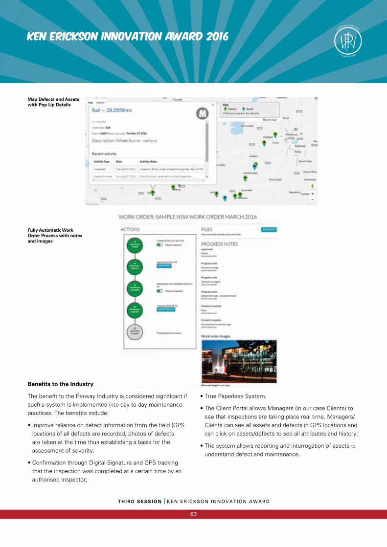
T H I R D S E S S I O N I K E N E R I C K S O N I N N O V A T I O N A W A R D
63
KEN ERICKSON INNOVATION AWARD 2016
Benefits to the Industry
The benefit to the Perway Industry is considered significant if such a system is implemented into day to day maintenance practices. The benefits include:
• Improve reliance on defect information from the field (GPS locations of all defects are recorded, photos of defects are taken at the time thus establishing a basis for the assessment of severity;
• Confirmation through Digital Signature and GPS tracking that the inspection was completed at a certain time by an authorised Inspector;
• True Paperless System;
• The Client Portal allows Managers (in our case Clients) to see that inspections are taking place real time. Managers/Clients can see all assets and defects in GPS locations and can click on assets/defects to see all attributes and history;
• The system allows reporting and interrogation of assets to
understand defect and maintenance.
Fully Automatic Work Order Process with notes and images
Map Defects and Assets with Pop Up Details
2016 STEVE MAXWELL PLATELAYING AWARD
T H I R D S E S S I O N I S T E V E M A X W E L L P L A T E L A Y I N G A W A R D
64
Mark Harris – Lendlease
Stephen Fleck – John Holland
Bob Ford – Ford Rail Management P/L
Judges
Steve Maxwell was a Member of the Permanent Way Institution Committee for many years, and his hard work and dedication enabled the PWI to continue during some difficult times. Steve was an informed Judge of the Platelaying Award, and also an entertaining speaker and presenter.
Steve’s rail career began in NSW after graduating in Civil Engineering in 1970 and he progressed from District Engineer to become General Manager Engineering for CityRail, covering the suburban and interurban areas of Sydney. He made a huge contribution to the rail industry through his early advocacy of asset management as a key part of the rail engineering discipline, and with the introduction of numerous new infrastructure maintenance and asset management techniques and capabilities.
Steve’s untimely and premature death in 1997 was a great loss to the PWI and took from the industry a great engineer, friend and personable and supportive leader.
The Committee deemed it appropriate to name the prestigious Platelaying Award after Steve Maxwell.
This annual Award is made to encourage excellence in platelaying, and to bring to public notice the skills required to gain such excellence. The Award is made to the staff responsible, who in the opinion of the Judges, best demonstrate this excellence. In other words, the Award will indicate a permanent way job well done.
Eligible projects are any track renewal, or construction work, completed in the last financial year by, or under the control of, a Member of the NSW Section, whether on a government or private railway system.
There are two Platelaying Awards – one for Minor Works (less than $3m in value) and one for Major Works (greater than $3m in value).
Scoring Category Available Score
Accuracy to Design and Survey 50
Site Presentation 50
Neatness of Fit of Components 50
Difficulties Overcome 25
Safety 25
Consideration of the Environment 25
Closeness to Planning and Timetable 25
Closeness to Budget 25
Level of Client Satisfaction 25
Total Score/Marks: 300
Steve Maxwell
Judging Criteria:
T H I R D S E S S I O N I S T E V E M A X W E L L P L A T E L A Y I N G A W A R D
65
2016 STEVE MAXWELL PLATELAYING AWARD
30TAL Loops Track Strengthening – Togar, Murulla, Emerald Hill & BoggabriLaing O’Rourke – Hunter Valley Rail OperationsSimon Battersby – Project Manager
Epping to Thornleigh Third Track (Sydney, NSW)CPB Contractors (ETTT Alliance)Craig Brown – Project Manager
Lewisham Re-transoming works
Laing O’Rourke
Mark McNally – SRO Operations Manager
Veolia Rail Facility, Banksmeadow
Rhomberg Rail Australia
Company representative – Hasan Onay Site Engineer
Scone Passenger Loop Reconditioning, Scone NSW
Laing O’Rourke
Simon Battersby – Project Manager
Plasser Rail Yard Upgrade, St Marys NSW
Rhomberg Rail Australia
Sarah-Ann Brennan, Project Manager
Wingercaribbee Viaduct – Retransoming – Down Main,
Burradoo – NSW
Australian Rail Track Corporation
Tofi q Ahmed – Project Manager
Major Works Entries – > $3MMinor Works Entries – < $3M
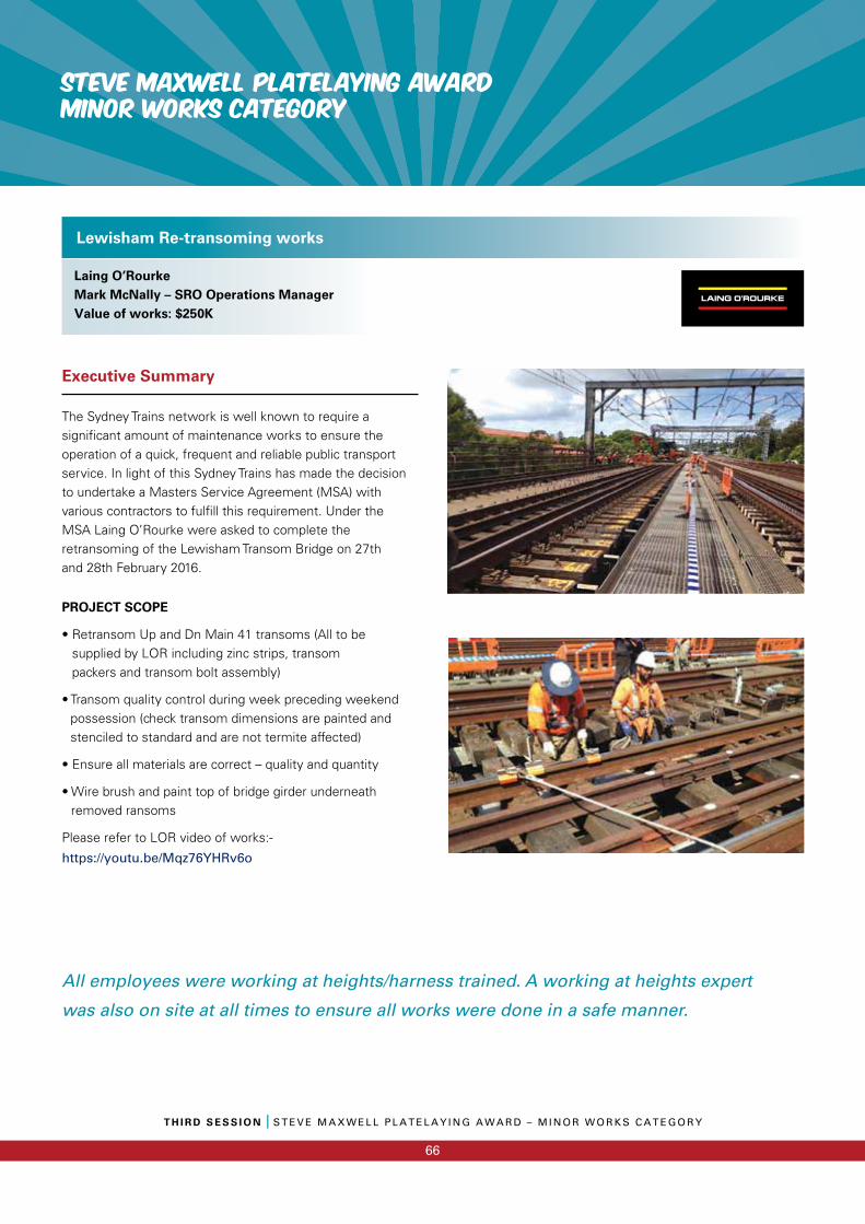
STEVE MAXWELL PLATELAYING AWARDMINOR WORKS CATEGORY
T H I R D S E S S I O N I S T E V E M A X W E L L P L A T E L A Y I N G A W A R D – M I N O R W O R K S C A T E G O R Y
66
Executive Summary
The Sydney Trains network is well known to require a signifi cant amount of maintenance works to ensure the operation of a quick, frequent and reliable public transport service. In light of this Sydney Trains has made the decision to undertake a Masters Service Agreement (MSA) with various contractors to fulfi ll this requirement. Under the MSA Laing O’Rourke were asked to complete the retransoming of the Lewisham Transom Bridge on 27th and 28th February 2016.
PROJECT SCOPE
• Retransom Up and Dn Main 41 transoms (All to be supplied by LOR including zinc strips, transom packers and transom bolt assembly)
• Transom quality control during week preceding weekend possession (check transom dimensions are painted and stenciled to standard and are not termite affected)
• Ensure all materials are correct – quality and quantity
• Wire brush and paint top of bridge girder underneath removed ransoms
Please refer to LOR video of works:-
https://youtu.be/Mqz76YHRv6o
Lewisham Re-transoming works
Laing O’RourkeMark McNally – SRO Operations ManagerValue of works: $250K
All employees were working at heights/harness trained. A working at heights expert
was also on site at all times to ensure all works were done in a safe manner.
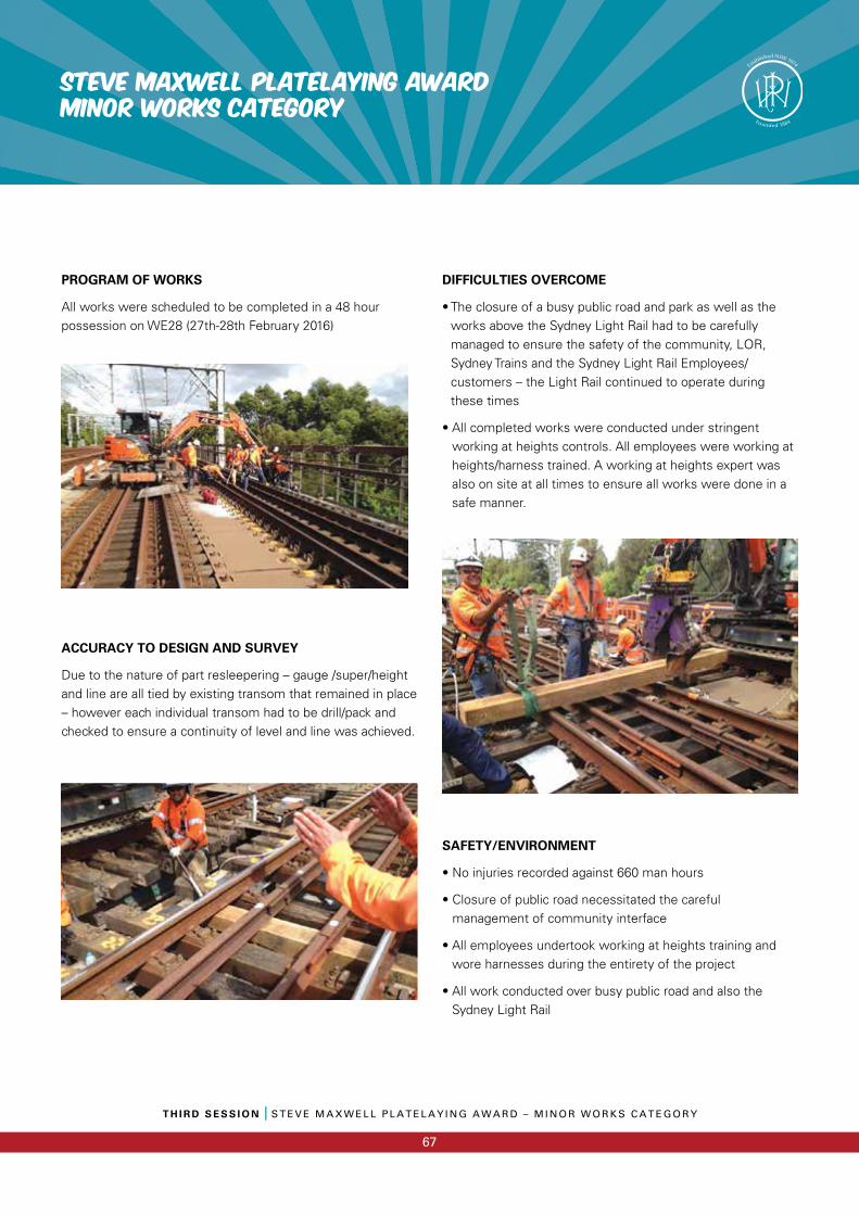
T H I R D S E S S I O N I S T E V E M A X W E L L P L A T E L A Y I N G A W A R D – M I N O R W O R K S C A T E G O R Y
67
STEVE MAXWELL PLATELAYING AWARDMINOR WORKS CATEGORY
PROGRAM OF WORKS
All works were scheduled to be completed in a 48 hour possession on WE28 (27th-28th February 2016)
ACCURACY TO DESIGN AND SURVEY
Due to the nature of part resleepering – gauge /super/height and line are all tied by existing transom that remained in place – however each individual transom had to be drill/pack and checked to ensure a continuity of level and line was achieved.
DIFFICULTIES OVERCOME
• The closure of a busy public road and park as well as the works above the Sydney Light Rail had to be carefully managed to ensure the safety of the community, LOR, Sydney Trains and the Sydney Light Rail Employees/customers – the Light Rail continued to operate during these times
• All completed works were conducted under stringent working at heights controls. All employees were working at heights/harness trained. A working at heights expert was also on site at all times to ensure all works were done in a safe manner.
SAFETY/ENVIRONMENT
• No injuries recorded against 660 man hours
• Closure of public road necessitated the careful management of community interface
• All employees undertook working at heights training and wore harnesses during the entirety of the project
• All work conducted over busy public road and also the Sydney Light Rail
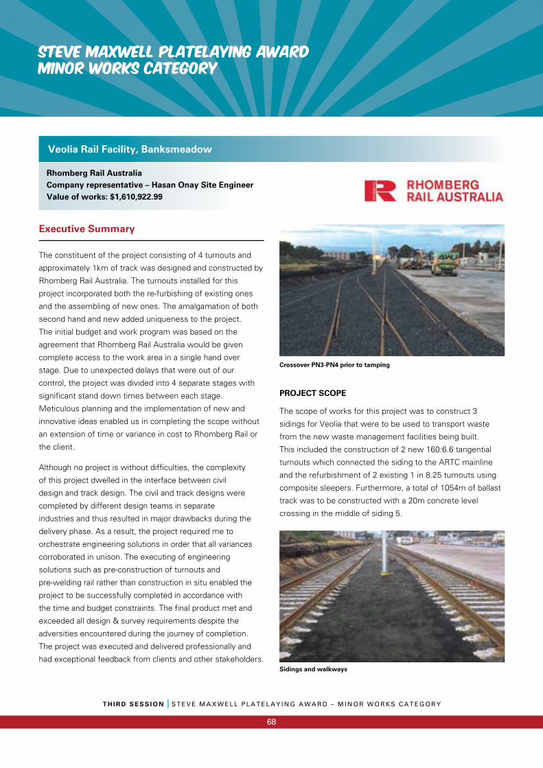
STEVE MAXWELL PLATELAYING AWARDMINOR WORKS CATEGORY
T H I R D S E S S I O N I S T E V E M A X W E L L P L A T E L A Y I N G A W A R D – M I N O R W O R K S C A T E G O R Y
68
Executive Summary
The constituent of the project consisting of 4 turnouts and
approximately 1km of track was designed and constructed by
Rhomberg Rail Australia. The turnouts installed for this
project incorporated both the re-furbishing of existing ones
and the assembling of new ones. The amalgamation of both
second hand and new added uniqueness to the project.
The initial budget and work program was based on the
agreement that Rhomberg Rail Australia would be given
complete access to the work area in a single hand over
stage. Due to unexpected delays that were out of our
control, the project was divided into 4 separate stages with
significant stand down times between each stage.
Meticulous planning and the implementation of new and
innovative ideas enabled us in completing the scope without
an extension of time or variance in cost to Rhomberg Rail or
the client.
Although no project is without difficulties, the complexity
of this project dwelled in the interface between civil
design and track design. The civil and track designs were
completed by different design teams in separate
industries and thus resulted in major drawbacks during the
delivery phase. As a result, the project required me to
orchestrate engineering solutions in order that all variances
corroborated in unison. The executing of engineering
solutions such as pre-construction of turnouts and
pre-welding rail rather than construction in situ enabled the
project to be successfully completed in accordance with
the time and budget constraints. The final product met and
exceeded all design & survey requirements despite the
adversities encountered during the journey of completion.
The project was executed and delivered professionally and
had exceptional feedback from clients and other stakeholders.
Crossover PN3-PN4 prior to tamping
PROJECT SCOPE
The scope of works for this project was to construct 3
sidings for Veolia that were to be used to transport waste
from the new waste management facilities being built.
This included the construction of 2 new 160:6.6 tangential
turnouts which connected the siding to the ARTC mainline
and the refurbishment of 2 existing 1 in 8.25 turnouts using
composite sleepers. Furthermore, a total of 1054m of ballast
track was to be constructed with a 20m concrete level
crossing in the middle of siding 5.
Veolia Rail Facility, Banksmeadow
Rhomberg Rail AustraliaCompany representative – Hasan Onay Site EngineerValue of works: $1,610,922.99
Sidings and walkways
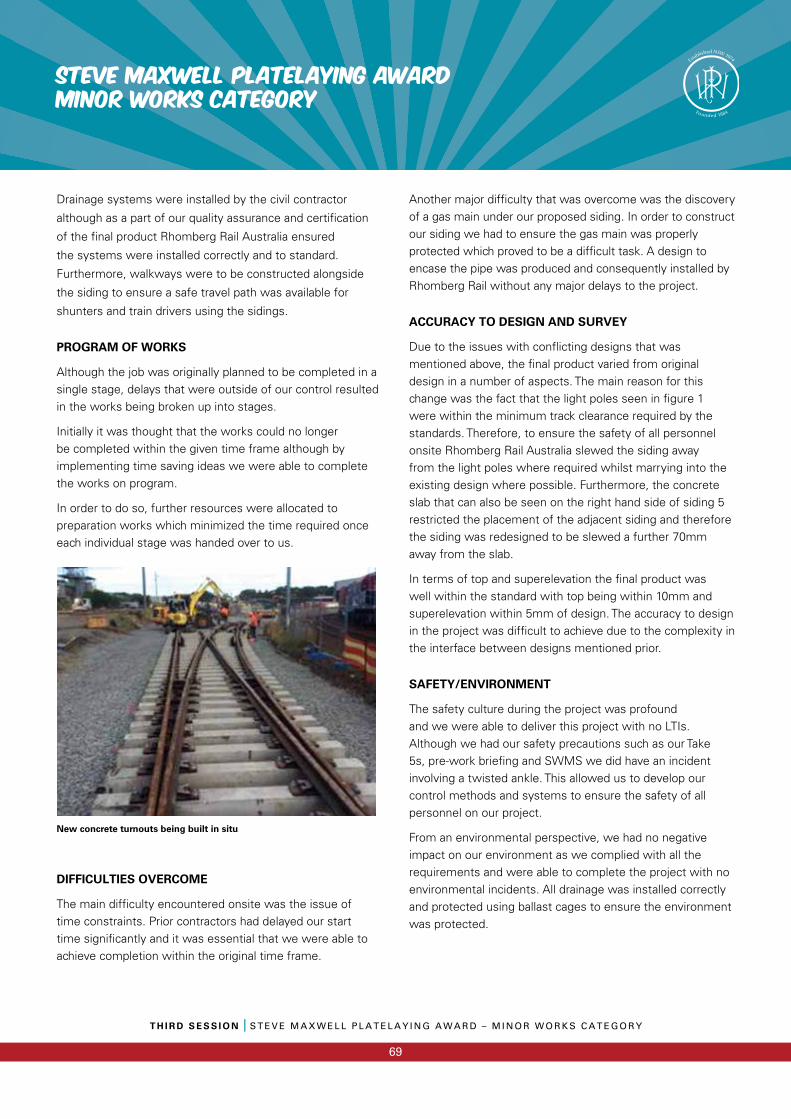
T H I R D S E S S I O N I S T E V E M A X W E L L P L A T E L A Y I N G A W A R D – M I N O R W O R K S C A T E G O R Y
69
STEVE MAXWELL PLATELAYING AWARDMINOR WORKS CATEGORY
Drainage systems were installed by the civil contractor
although as a part of our quality assurance and certification
of the final product Rhomberg Rail Australia ensured
the systems were installed correctly and to standard.
Furthermore, walkways were to be constructed alongside
the siding to ensure a safe travel path was available for
shunters and train drivers using the sidings.
PROGRAM OF WORKS
Although the job was originally planned to be completed in a single stage, delays that were outside of our control resulted in the works being broken up into stages.
Initially it was thought that the works could no longer be completed within the given time frame although by implementing time saving ideas we were able to complete the works on program.
In order to do so, further resources were allocated to preparation works which minimized the time required once each individual stage was handed over to us.
New concrete turnouts being built in situ
DIFFICULTIES OVERCOME
The main diffi culty encountered onsite was the issue of time constraints. Prior contractors had delayed our start time signifi cantly and it was essential that we were able to achieve completion within the original time frame.
Another major diffi culty that was overcome was the discovery of a gas main under our proposed siding. In order to construct our siding we had to ensure the gas main was properly protected which proved to be a diffi cult task. A design to encase the pipe was produced and consequently installed by Rhomberg Rail without any major delays to the project.
ACCURACY TO DESIGN AND SURVEY
Due to the issues with confl icting designs that was mentioned above, the fi nal product varied from original design in a number of aspects. The main reason for this change was the fact that the light poles seen in fi gure 1 were within the minimum track clearance required by the standards. Therefore, to ensure the safety of all personnel onsite Rhomberg Rail Australia slewed the siding away from the light poles where required whilst marrying into the existing design where possible. Furthermore, the concrete slab that can also be seen on the right hand side of siding 5 restricted the placement of the adjacent siding and therefore the siding was redesigned to be slewed a further 70mm away from the slab.
In terms of top and superelevation the fi nal product was well within the standard with top being within 10mm and superelevation within 5mm of design. The accuracy to design in the project was diffi cult to achieve due to the complexity in the interface between designs mentioned prior.
SAFETY/ENVIRONMENT
The safety culture during the project was profound and we were able to deliver this project with no LTIs. Although we had our safety precautions such as our Take 5s, pre-work briefi ng and SWMS we did have an incident involving a twisted ankle. This allowed us to develop our control methods and systems to ensure the safety of all personnel on our project.
From an environmental perspective, we had no negative impact on our environment as we complied with all the requirements and were able to complete the project with no environmental incidents. All drainage was installed correctly and protected using ballast cages to ensure the environment was protected.
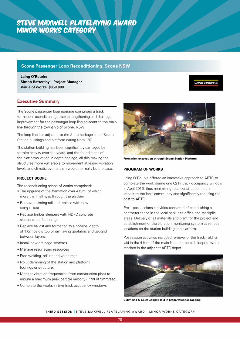
STEVE MAXWELL PLATELAYING AWARDMINOR WORKS CATEGORY
T H I R D S E S S I O N I S T E V E M A X W E L L P L A T E L A Y I N G A W A R D – M I N O R W O R K S C A T E G O R Y
70
Executive Summary
The Scone passenger loop upgrade comprised a track formation reconditioning, track strengthening and drainage improvement for the passenger loop line adjacent to the main line through the township of Scone, NSW.
The loop line lies adjacent to the State heritage listed Scone Station buildings and platform dating from 1871.
The station building has been significantly damaged by termite activity over the years, and the foundations of the platforms varied in depth and age; all this making the structures more vulnerable to movement at lesser vibration levels and climatic events than would normally be the case.
PROJECT SCOPE
The reconditioning scope of works comprised:• The upgrade of the formation over 413m, of which
more than half was through the platform
• Remove existing rail and replace with new 60kg HHrail
• Replace timber sleepers with HDFC concrete sleepers and fastenings
• Replace ballast and formation to a nominal depth of 1.0m below top of rail, laying geofabric and geogrid between layers.
• Install new drainage systems
• Manage resurfacing resources
• Free welding, adjust and verse test
• No undermining of the station and platform footings or structure.
• Monitor vibration frequencies from construction plant to ensure a maximum peak particle velocity (PPV) of 5mm/sec.
• Complete the works in two track occupancy windows
Formation excavation through Scone Station Platform
PROGRAM OF WORKS
Laing O’Rourke offered an innovative approach to ARTC to complete the work during one 62 hr track occupancy window in April 2016, thus minimising total construction hours, impact to the local community and significantly reducing the cost to ARTC.
Pre – possessions activities consisted of establishing a perimeter fence in the local park, site office and stockpile areas. Delivery of all materials and plant for the project and establishment of the vibration monitoring system at various locations on the station building and platform.
Possession activities included removal of the track - old rail laid in the 4-foot of the main line and the old sleepers were stacked in the adjacent ARTC depot.
Scone Passenger Loop Reconditioning, Scone NSW
Laing O’RourkeSimon Battersby – Project ManagerValue of works: $850,000
Bidim A44 & SS30 Geogrid laid in preparation for capping
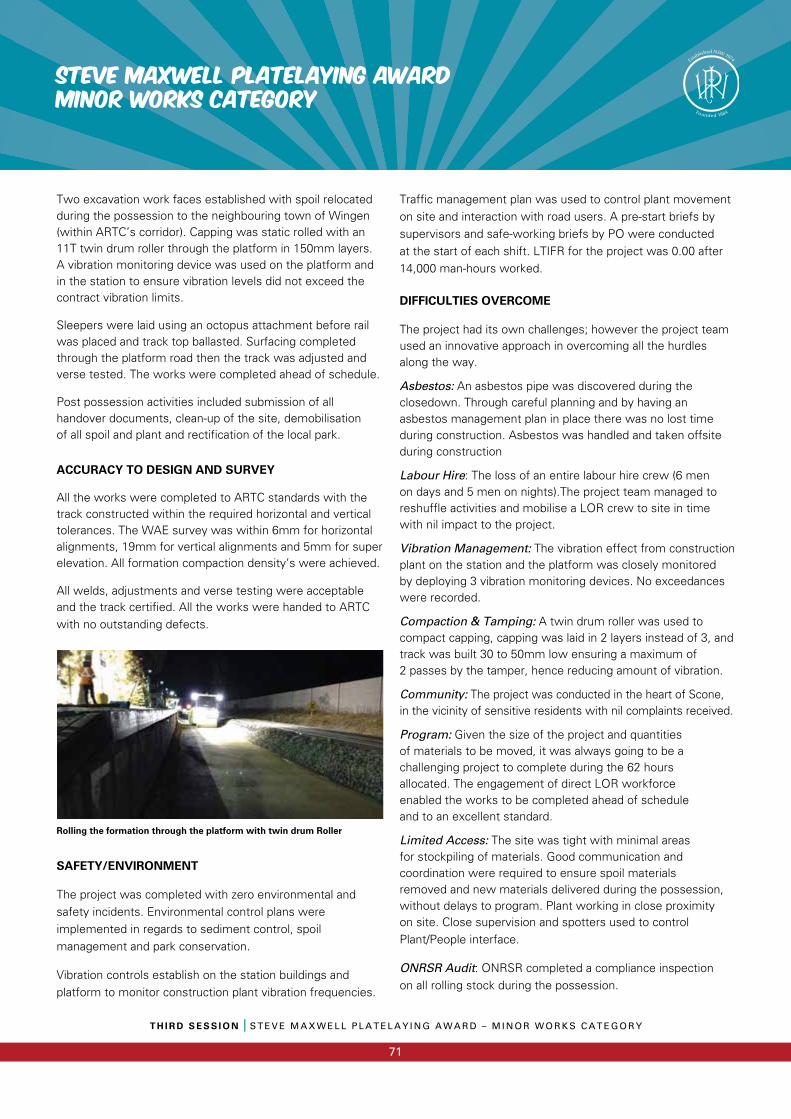
T H I R D S E S S I O N I S T E V E M A X W E L L P L A T E L A Y I N G A W A R D – M I N O R W O R K S C A T E G O R Y
71
STEVE MAXWELL PLATELAYING AWARDMINOR WORKS CATEGORY
Two excavation work faces established with spoil relocated during the possession to the neighbouring town of Wingen (within ARTC’s corridor). Capping was static rolled with an 11T twin drum roller through the platform in 150mm layers. A vibration monitoring device was used on the platform and in the station to ensure vibration levels did not exceed the contract vibration limits.
Sleepers were laid using an octopus attachment before rail was placed and track top ballasted. Surfacing completed through the platform road then the track was adjusted and verse tested. The works were completed ahead of schedule.
Post possession activities included submission of all handover documents, clean-up of the site, demobilisation of all spoil and plant and rectification of the local park.
ACCURACY TO DESIGN AND SURVEY
All the works were completed to ARTC standards with the track constructed within the required horizontal and vertical tolerances. The WAE survey was within 6mm for horizontal alignments, 19mm for vertical alignments and 5mm for super elevation. All formation compaction density’s were achieved.
All welds, adjustments and verse testing were acceptable and the track certified. All the works were handed to ARTC with no outstanding defects.
Rolling the formation through the platform with twin drum Roller
SAFETY/ENVIRONMENT
The project was completed with zero environmental and safety incidents. Environmental control plans were implemented in regards to sediment control, spoil management and park conservation.
Vibration controls establish on the station buildings and platform to monitor construction plant vibration frequencies.
Traffic management plan was used to control plant movement on site and interaction with road users. A pre-start briefs by supervisors and safe-working briefs by PO were conducted at the start of each shift. LTIFR for the project was 0.00 after 14,000 man-hours worked.
DIFFICULTIES OVERCOME
The project had its own challenges; however the project team used an innovative approach in overcoming all the hurdles along the way.
Asbestos: An asbestos pipe was discovered during the closedown. Through careful planning and by having an asbestos management plan in place there was no lost time during construction. Asbestos was handled and taken offsite during construction
Labour Hire: The loss of an entire labour hire crew (6 men on days and 5 men on nights).The project team managed to reshuffle activities and mobilise a LOR crew to site in time with nil impact to the project.
Vibration Management: The vibration effect from construction plant on the station and the platform was closely monitored by deploying 3 vibration monitoring devices. No exceedances were recorded.
Compaction & Tamping: A twin drum roller was used to compact capping, capping was laid in 2 layers instead of 3, and track was built 30 to 50mm low ensuring a maximum of 2 passes by the tamper, hence reducing amount of vibration.
Community: The project was conducted in the heart of Scone, in the vicinity of sensitive residents with nil complaints received.
Program: Given the size of the project and quantities of materials to be moved, it was always going to be a challenging project to complete during the 62 hours allocated. The engagement of direct LOR workforce enabled the works to be completed ahead of schedule and to an excellent standard.
Limited Access: The site was tight with minimal areas for stockpiling of materials. Good communication and coordination were required to ensure spoil materials removed and new materials delivered during the possession, without delays to program. Plant working in close proximity on site. Close supervision and spotters used to control Plant/People interface.
ONRSR Audit: ONRSR completed a compliance inspectionon all rolling stock during the possession.
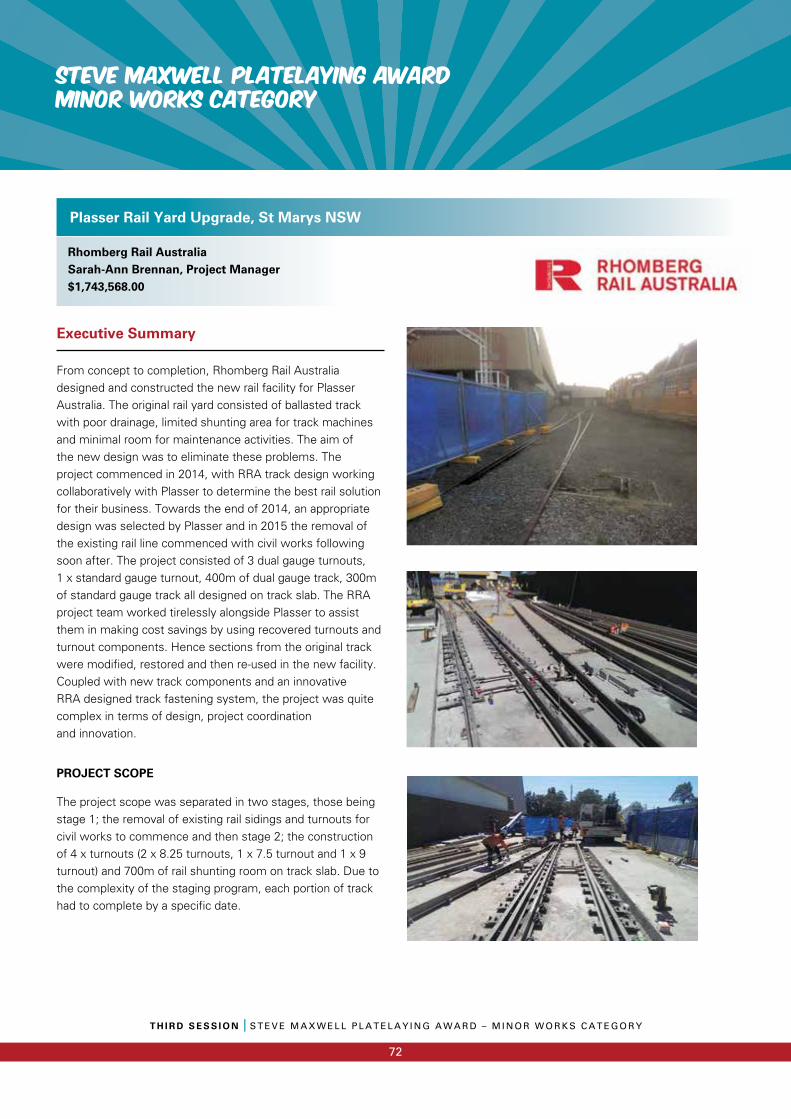
STEVE MAXWELL PLATELAYING AWARDMINOR WORKS CATEGORY
T H I R D S E S S I O N I S T E V E M A X W E L L P L A T E L A Y I N G A W A R D – M I N O R W O R K S C A T E G O R Y
72
Executive Summary
From concept to completion, Rhomberg Rail Australia designed and constructed the new rail facility for Plasser Australia. The original rail yard consisted of ballasted track with poor drainage, limited shunting area for track machines and minimal room for maintenance activities. The aim of the new design was to eliminate these problems. The project commenced in 2014, with RRA track design working collaboratively with Plasser to determine the best rail solution for their business. Towards the end of 2014, an appropriate design was selected by Plasser and in 2015 the removal of the existing rail line commenced with civil works following soon after. The project consisted of 3 dual gauge turnouts, 1 x standard gauge turnout, 400m of dual gauge track, 300m of standard gauge track all designed on track slab. The RRA project team worked tirelessly alongside Plasser to assist them in making cost savings by using recovered turnouts and turnout components. Hence sections from the original track were modified, restored and then re-used in the new facility. Coupled with new track components and an innovative RRA designed track fastening system, the project was quite complex in terms of design, project coordination and innovation.
PROJECT SCOPE
The project scope was separated in two stages, those being stage 1; the removal of existing rail sidings and turnouts for civil works to commence and then stage 2; the construction of 4 x turnouts (2 x 8.25 turnouts, 1 x 7.5 turnout and 1 x 9 turnout) and 700m of rail shunting room on track slab. Due to the complexity of the staging program, each portion of track had to complete by a specific date.
Plasser Rail Yard Upgrade, St Marys NSW
Rhomberg Rail AustraliaSarah-Ann Brennan, Project Manager$1,743,568.00
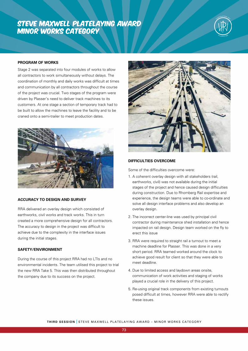
T H I R D S E S S I O N I S T E V E M A X W E L L P L A T E L A Y I N G A W A R D – M I N O R W O R K S C A T E G O R Y
73
STEVE MAXWELL PLATELAYING AWARDMINOR WORKS CATEGORY
PROGRAM OF WORKS
Stage 2 was separated into four modules of works to allow
all contractors to work simultaneously without delays. The
coordination of monthly and daily works was difficult at times
and communication by all contractors throughout the course
of the project was crucial. Two stages of the program were
driven by Plasser’s need to deliver track machines to its
customers. At one stage a section of temporary track had to
be built to allow the machines to leave the facility and to be
craned onto a semi-trailer to meet production dates.
ACCURACY TO DESIGN AND SURVEY
RRA delivered an overlay design which consisted of
earthworks, civil works and track works. This in turn
created a more comprehensive design for all contractors.
The accuracy to design in the project was difficult to
achieve due to the complexity in the interface issues
during the initial stages.
SAFETY/ENVIRONMENT
During the course of this project RRA had no LTIs and no
environmental incidents. The team utilised this project to trial
the new RRA Take 5. This was then distributed throughout
the company due to its success on the project.
DIFFICULTIES OVERCOME
Some of the difficulties overcome were:
1. A coherent overlay design with all stakeholders (rail, earthworks, civil) was not available during the initial stages of the project and hence caused design difficulties during construction. Due to Rhomberg Rail expertise and experience, the design teams were able to co-ordinate and solve all design interface problems and also develop an overlay design.
2. The incorrect center-line was used by principal civil contractor during maintenance shed installation and hence impacted on rail design. Design team worked on the fly to erect this issue
3. RRA were required to straight rail a turnout to meet a machine deadline for Plasser. This was done in a very short period. RRA teamed worked around the clock to achieve good result for client so that they were able to meet deadline.
4. Due to limited access and laydown areas onsite, communication of work activities and staging of works played a crucial role in the delivery of this project.
5. Re-using original track components from existing turnouts posed difficult at times, however RRA were able to rectify these issues.
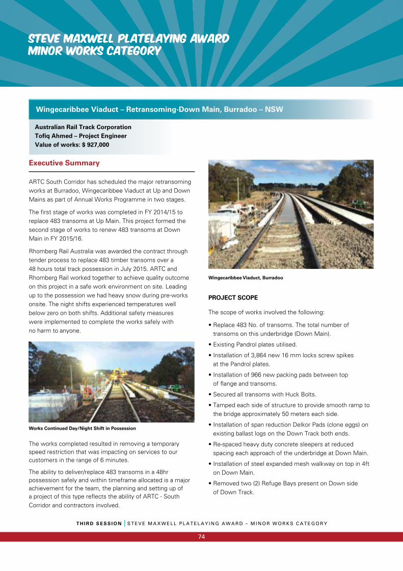
STEVE MAXWELL PLATELAYING AWARDMINOR WORKS CATEGORY
T H I R D S E S S I O N I S T E V E M A X W E L L P L A T E L A Y I N G A W A R D – M I N O R W O R K S C A T E G O R Y
74
Executive Summary
ARTC South Corridor has scheduled the major retransoming works at Burradoo, Wingecaribbee Viaduct at Up and Down Mains as part of Annual Works Programme in two stages.
The first stage of works was completed in FY 2014/15 to replace 483 transoms at Up Main. This project formed the second stage of works to renew 483 transoms at Down Main in FY 2015/16.
Rhomberg Rail Australia was awarded the contract through tender process to replace 483 timber transoms over a 48 hours total track possession in July 2015. ARTC and Rhomberg Rail worked together to achieve quality outcome on this project in a safe work environment on site. Leading up to the possession we had heavy snow during pre-works onsite. The night shifts experienced temperatures well below zero on both shifts. Additional safety measures were implemented to complete the works safely with no harm to anyone.
Works Continued Day/Night Shift in Possession
The works completed resulted in removing a temporary speed restriction that was impacting on services to our customers in the range of 6 minutes.
The ability to deliver/replace 483 transoms in a 48hr possession safely and within timeframe allocated is a major achievement for the team, the planning and setting up of a project of this type reflects the ability of ARTC - South Corridor and contractors involved.
Wingecaribbee Viaduct, Burradoo
PROJECT SCOPE
The scope of works involved the following:
• Replace 483 No. of transoms. The total number of transoms on this underbridge (Down Main).
• Existing Pandrol plates utilised.
• Installation of 3,864 new 16 mm locks screw spikes at the Pandrol plates.
• Installation of 966 new packing pads between top of flange and transoms.
• Secured all transoms with Huck Bolts.
• Tamped each side of structure to provide smooth ramp to the bridge approximately 50 meters each side.
• Installation of span reduction Delkor Pads (clone eggs) on existing ballast logs on the Down Track both ends.
• Re-spaced heavy duty concrete sleepers at reduced spacing each approach of the underbridge at Down Main.
• Installation of steel expanded mesh walkway on top in 4ft on Down Main.
• Removed two (2) Refuge Bays present on Down side of Down Track.
Wingecaribbee Viaduct – Retransoming-Down Main, Burradoo – NSW
Australian Rail Track CorporationTofiq Ahmed – Project EngineerValue of works: $ 927,000
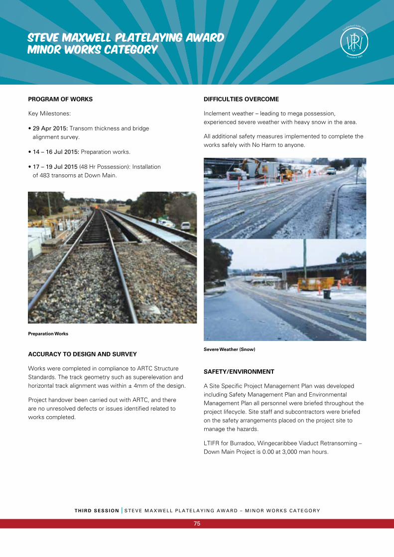
T H I R D S E S S I O N I S T E V E M A X W E L L P L A T E L A Y I N G A W A R D – M I N O R W O R K S C A T E G O R Y
75
STEVE MAXWELL PLATELAYING AWARDMINOR WORKS CATEGORY
PROGRAM OF WORKS
Key Milestones:
• 29 Apr 2015: Transom thickness and bridge alignment survey.
• 14 – 16 Jul 2015: Preparation works.
• 17 – 19 Jul 2015 (48 Hr Possession): Installation of 483 transoms at Down Main.
Preparation Works
ACCURACY TO DESIGN AND SURVEY
Works were completed in compliance to ARTC Structure Standards. The track geometry such as superelevation and horizontal track alignment was within ± 4mm of the design.
Project handover been carried out with ARTC, and there are no unresolved defects or issues identified related to works completed.
DIFFICULTIES OVERCOME
Inclement weather – leading to mega possession, experienced severe weather with heavy snow in the area.
All additional safety measures implemented to complete the works safely with No Harm to anyone.
Severe Weather (Snow)
SAFETY/ENVIRONMENT
A Site Specific Project Management Plan was developed including Safety Management Plan and Environmental Management Plan all personnel were briefed throughout the project lifecycle. Site staff and subcontractors were briefed on the safety arrangements placed on the project site to manage the hazards.
LTIFR for Burradoo, Wingecaribbee Viaduct Retransoming – Down Main Project is 0.00 at 3,000 man hours.
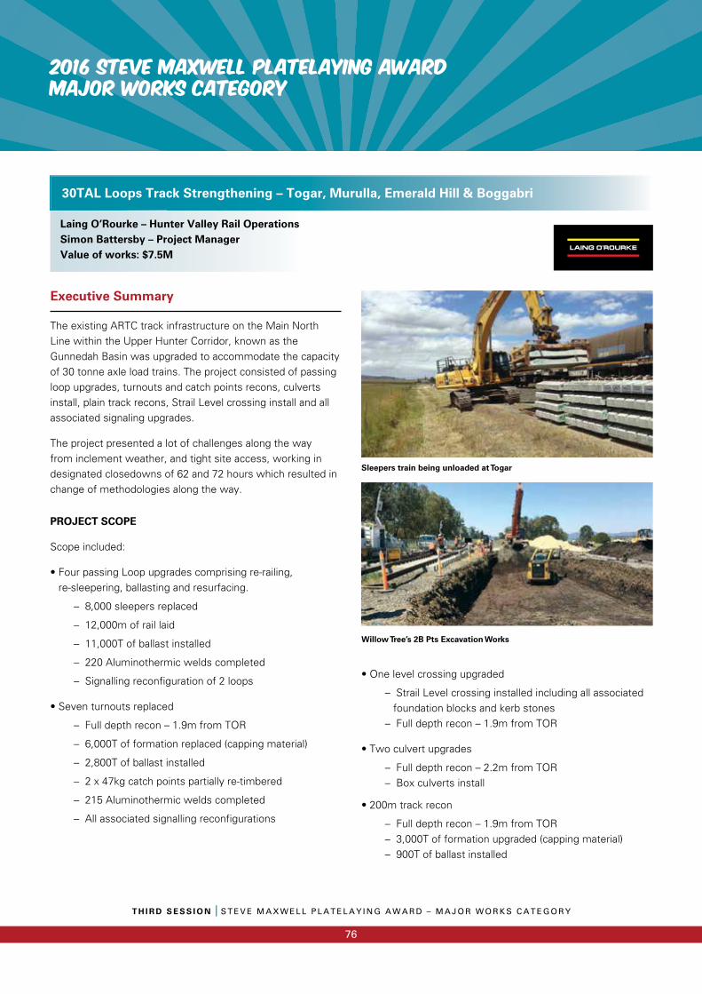
2016 STEVE MAXWELL PLATELAYING AWARDMAJOR WORKS CATEGORY
T H I R D S E S S I O N I S T E V E M A X W E L L P L A T E L A Y I N G A W A R D – M A J O R W O R K S C A T E G O R Y
76
Executive Summary
The existing ARTC track infrastructure on the Main North Line within the Upper Hunter Corridor, known as the Gunnedah Basin was upgraded to accommodate the capacity of 30 tonne axle load trains. The project consisted of passing loop upgrades, turnouts and catch points recons, culverts install, plain track recons, Strail Level crossing install and all associated signaling upgrades.
The project presented a lot of challenges along the way from inclement weather, and tight site access, working in designated closedowns of 62 and 72 hours which resulted in change of methodologies along the way.
PROJECT SCOPE
Scope included:
• Four passing Loop upgrades comprising re-railing, re-sleepering, ballasting and resurfacing.
– 8,000 sleepers replaced
– 12,000m of rail laid
– 11,000T of ballast installed
– 220 Aluminothermic welds completed
– Signalling reconfiguration of 2 loops
• Seven turnouts replaced
– Full depth recon – 1.9m from TOR
– 6,000T of formation replaced (capping material)
– 2,800T of ballast installed
– 2 x 47kg catch points partially re-timbered
– 215 Aluminothermic welds completed
– All associated signalling reconfigurations
Sleepers train being unloaded at Togar
Willow Tree’s 2B Pts Excavation Works
• One level crossing upgraded
– Strail Level crossing installed including all associated foundation blocks and kerb stones
– Full depth recon – 1.9m from TOR
• Two culvert upgrades
– Full depth recon – 2.2m from TOR – Box culverts install
• 200m track recon
– Full depth recon – 1.9m from TOR – 3,000T of formation upgraded (capping material) – 900T of ballast installed
30TAL Loops Track Strengthening – Togar, Murulla, Emerald Hill & Boggabri
Laing O’Rourke – Hunter Valley Rail OperationsSimon Battersby – Project ManagerValue of works: $7.5M
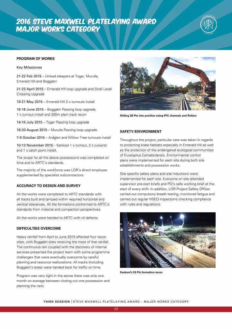
T H I R D S E S S I O N I S T E V E M A X W E L L P L A T E L A Y I N G A W A R D – M A J O R W O R K S C A T E G O R Y
77
2016 STEVE MAXWELL PLATELAYING AWARDMAJOR WORKS CATEGORY
PROGRAM OF WORKS
Key Milestones
21-22 Feb 2015 – Unload sleepers at Togar, Murulla, Emerald Hill and Boggabri
21-23 April 2015 – Emerald Hill loop upgrade and Strail Level Crossing Upgrade
19-21 May 2015 – Emerald Hill 2 x turnouts install
16-18 June 2015 – Boggabri Passing loop upgrade, 1 x turnout install and 200m plain track recon
14-16 July 2015 – Togar Passing loop upgrade
18-20 August 2015 – Murulla Passing loop upgrade
7-9 October 2015 – Ardglen and Willow Tree turnouts install
10-13 November 2015 – Kankool 1 x turnout, 2 x culverts and 1 x catch point install,
The scope for all the above possessions was completed on time and to ARTC’s standards.
The majority of the workforce was LOR’s direct employee supplemented by specialist subcontractors.
ACCURACY TO DESIGN AND SURVEY
All the works were completed to ARTC standards with all tracks built and tamped within required horizontal and vertical tolerances. All the formations conformed to ARTC’s standards from material and compaction perspectives.
All the works were handed to ARTC with nil defects.
DIFFICULTIES OVERCOME
Heavy rainfall from April to June 2015 affected four recon sites, with Boggabri sites receiving the most of that rainfall. The continuous rain coupled with the discovery of internal services presented the project team with some programme challenges that were eventually overcome by careful planning and resource reallocations. All tracks (including Boggabri’s sites) were handed back for traffic on time.
Program was very tight in the sense there was only one month on average between closing out one possession and planning the next.
Sliding 2B Pts into position using PFC channels and Rollers
SAFETY/ENVIRONMENT
Throughout the project, particular care was taken in regards to protecting koala habitats especially in Emerald Hill as well as the protection of the endangered ecological communities of Eucalyptus Camaldulensis. Environmental control plans were implemented for each site during both site establishments and possession works.
Site specific safety plans and site inductions were implemented for each site. Everyone on site attended supervisor pre-start briefs and PO’s safe working brief at the start of every shift. In addition, LOR Project Safety Officer carried out compulsory breath testing, monitored fatigue and carried out regular HSEQ inspections checking compliance with rules and regulations.
Kankool’s 53 Pts formation recon
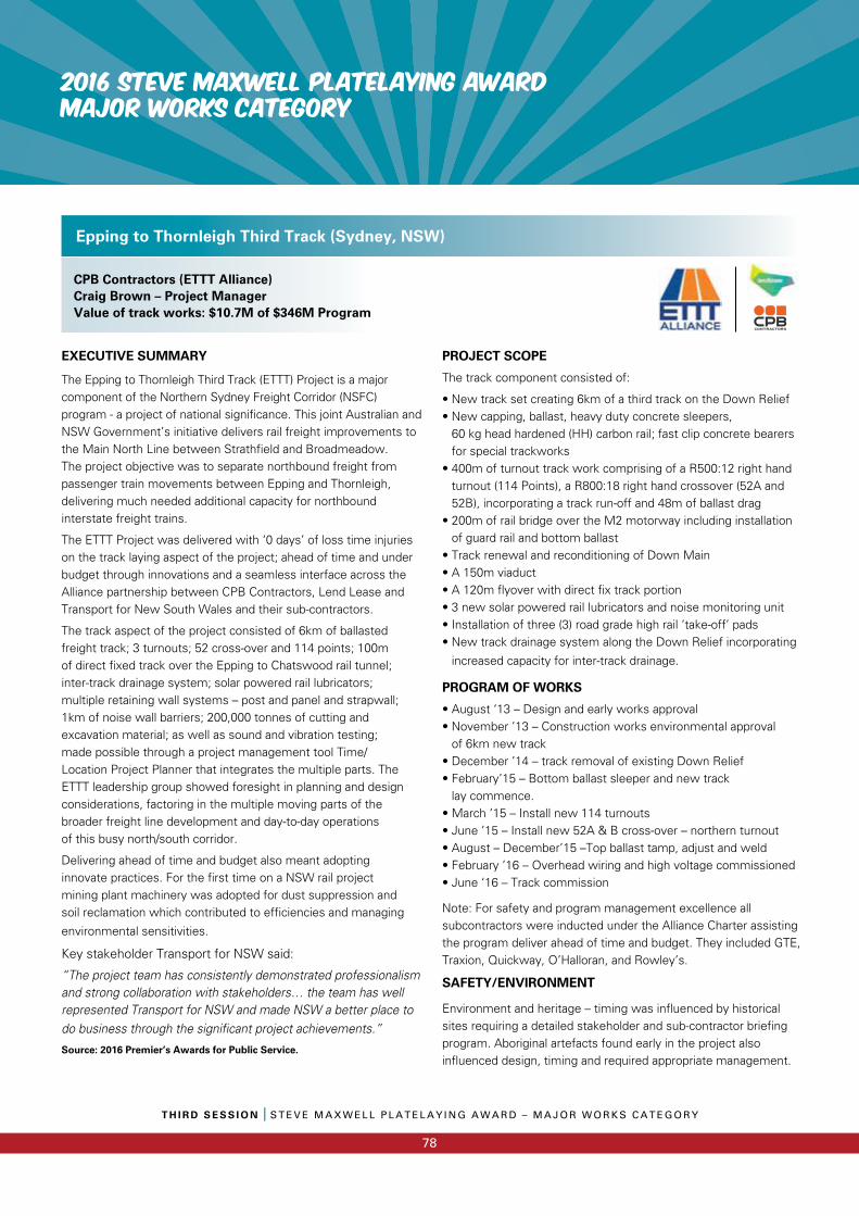
2016 STEVE MAXWELL PLATELAYING AWARDMAJOR WORKS CATEGORY
T H I R D S E S S I O N I S T E V E M A X W E L L P L A T E L A Y I N G A W A R D – M A J O R W O R K S C A T E G O R Y
78
EXECUTIVE SUMMARY
The Epping to Thornleigh Third Track (ETTT) Project is a majorcomponent of the Northern Sydney Freight Corridor (NSFC) program - a project of national significance. This joint Australian and NSW Government’s initiative delivers rail freight improvements to the Main North Line between Strathfield and Broadmeadow.The project objective was to separate northbound freight from passenger train movements between Epping and Thornleigh, delivering much needed additional capacity for northbound interstate freight trains.
The ETTT Project was delivered with ‘0 days’ of loss time injuries on the track laying aspect of the project; ahead of time and under budget through innovations and a seamless interface across the Alliance partnership between CPB Contractors, Lend Lease and Transport for New South Wales and their sub-contractors.
The track aspect of the project consisted of 6km of ballasted freight track; 3 turnouts; 52 cross-over and 114 points; 100m of direct fixed track over the Epping to Chatswood rail tunnel; inter-track drainage system; solar powered rail lubricators; multiple retaining wall systems – post and panel and strapwall; 1km of noise wall barriers; 200,000 tonnes of cutting and excavation material; as well as sound and vibration testing; made possible through a project management tool Time/Location Project Planner that integrates the multiple parts. The ETTT leadership group showed foresight in planning and design considerations, factoring in the multiple moving parts of the broader freight line development and day-to-day operations of this busy north/south corridor.
Delivering ahead of time and budget also meant adopting innovate practices. For the first time on a NSW rail project mining plant machinery was adopted for dust suppression and soil reclamation which contributed to efficiencies and managing
environmental sensitivities.
Key stakeholder Transport for NSW said:
“The project team has consistently demonstrated professionalism and strong collaboration with stakeholders… the team has well represented Transport for NSW and made NSW a better place to do business through the significant project achievements.”
Source: 2016 Premier’s Awards for Public Service.
PROJECT SCOPE
The track component consisted of:
• New track set creating 6km of a third track on the Down Relief• New capping, ballast, heavy duty concrete sleepers,
60 kg head hardened (HH) carbon rail; fast clip concrete bearers for special trackworks
• 400m of turnout track work comprising of a R500:12 right hand turnout (114 Points), a R800:18 right hand crossover (52A and 52B), incorporating a track run-off and 48m of ballast drag
• 200m of rail bridge over the M2 motorway including installation of guard rail and bottom ballast
• Track renewal and reconditioning of Down Main• A 150m viaduct• A 120m flyover with direct fix track portion• 3 new solar powered rail lubricators and noise monitoring unit• Installation of three (3) road grade high rail ‘take-off’ pads• New track drainage system along the Down Relief incorporating
increased capacity for inter-track drainage.
PROGRAM OF WORKS
• August ‘13 – Design and early works approval• November ’13 – Construction works environmental approval
of 6km new track• December ’14 – track removal of existing Down Relief• February’15 – Bottom ballast sleeper and new track
lay commence.• March ’15 – Install new 114 turnouts• June ’15 – Install new 52A & B cross-over – northern turnout• August – December’15 –Top ballast tamp, adjust and weld• February ’16 – Overhead wiring and high voltage commissioned• June ‘16 – Track commission
Note: For safety and program management excellence all subcontractors were inducted under the Alliance Charter assisting the program deliver ahead of time and budget. They included GTE, Traxion, Quickway, O’Halloran, and Rowley’s.
SAFETY/ENVIRONMENT
Environment and heritage – timing was influenced by historical sites requiring a detailed stakeholder and sub-contractor briefing program. Aboriginal artefacts found early in the project also influenced design, timing and required appropriate management.
Epping to Thornleigh Third Track (Sydney, NSW)
CPB Contractors (ETTT Alliance)Craig Brown – Project ManagerValue of track works: $10.7M of $346M Program
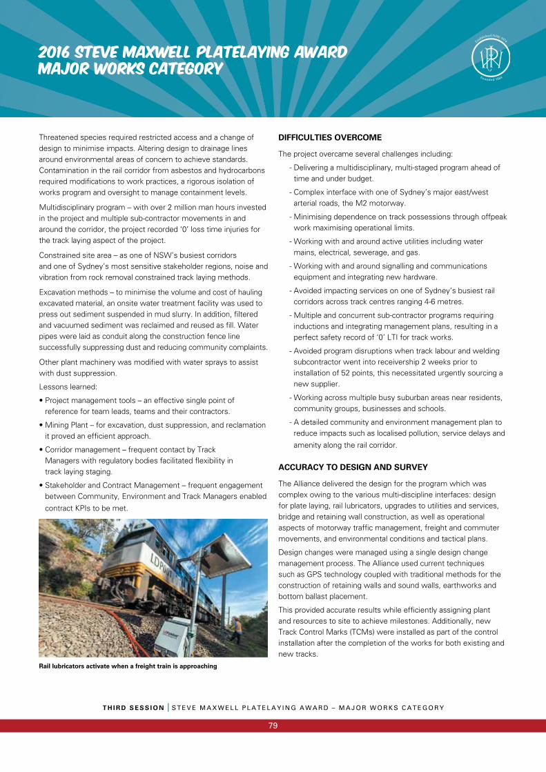
T H I R D S E S S I O N I S T E V E M A X W E L L P L A T E L A Y I N G A W A R D – M A J O R W O R K S C A T E G O R Y
79
2016 STEVE MAXWELL PLATELAYING AWARDMAJOR WORKS CATEGORY
Threatened species required restricted access and a change of design to minimise impacts. Altering design to drainage lines around environmental areas of concern to achieve standards. Contamination in the rail corridor from asbestos and hydrocarbons required modifications to work practices, a rigorous isolation of works program and oversight to manage containment levels.
Multidisciplinary program – with over 2 million man hours invested in the project and multiple sub-contractor movements in and around the corridor, the project recorded ‘0’ loss time injuries for the track laying aspect of the project.
Constrained site area – as one of NSW’s busiest corridors and one of Sydney’s most sensitive stakeholder regions, noise and vibration from rock removal constrained track laying methods.
Excavation methods – to minimise the volume and cost of hauling excavated material, an onsite water treatment facility was used to press out sediment suspended in mud slurry. In addition, filtered and vacuumed sediment was reclaimed and reused as fill. Water pipes were laid as conduit along the construction fence line successfully suppressing dust and reducing community complaints.
Other plant machinery was modified with water sprays to assist with dust suppression.
Lessons learned:
• Project management tools – an effective single point of reference for team leads, teams and their contractors.
• Mining Plant – for excavation, dust suppression, and reclamation it proved an efficient approach.
• Corridor management – frequent contact by Track Managers with regulatory bodies facilitated flexibility in track laying staging.
• Stakeholder and Contract Management – frequent engagement between Community, Environment and Track Managers enabled
contract KPIs to be met.
Rail lubricators activate when a freight train is approaching
DIFFICULTIES OVERCOME
The project overcame several challenges including:
- Delivering a multidisciplinary, multi-staged program ahead of time and under budget.
- Complex interface with one of Sydney’s major east/west arterial roads, the M2 motorway.
- Minimising dependence on track possessions through offpeak work maximising operational limits.
- Working with and around active utilities including water mains, electrical, sewerage, and gas.
- Working with and around signalling and communications equipment and integrating new hardware.
- Avoided impacting services on one of Sydney’s busiest rail corridors across track centres ranging 4-6 metres.
- Multiple and concurrent sub-contractor programs requiring inductions and integrating management plans, resulting in a perfect safety record of ‘0’ LTI for track works.
- Avoided program disruptions when track labour and welding subcontractor went into receivership 2 weeks prior to installation of 52 points, this necessitated urgently sourcing a new supplier.
- Working across multiple busy suburban areas near residents, community groups, businesses and schools.
- A detailed community and environment management plan to reduce impacts such as localised pollution, service delays and
amenity along the rail corridor.
ACCURACY TO DESIGN AND SURVEY
The Alliance delivered the design for the program which wascomplex owing to the various multi-discipline interfaces: design for plate laying, rail lubricators, upgrades to utilities and services, bridge and retaining wall construction, as well as operational aspects of motorway traffic management, freight and commuter movements, and environmental conditions and tactical plans.
Design changes were managed using a single design changemanagement process. The Alliance used current techniques such as GPS technology coupled with traditional methods for the construction of retaining walls and sound walls, earthworks and bottom ballast placement.
This provided accurate results while efficiently assigning plant and resources to site to achieve milestones. Additionally, new Track Control Marks (TCMs) were installed as part of the control installation after the completion of the works for both existing and new tracks.
THE NSW PWI IS PROUDLY SUPPORTED BY ITS SILVER CORPORATE MEMBERS
ARCHSERVICES
PERMANENT WAY INSTITUTION NSW
PO BOX 81, CAMDEN NSW 2570
PWINSW.ORG.AU
The PWI is proudly supported by its hero members